grid west project alternative north mayo substation sites ... · substation required, with...
TRANSCRIPT

Grid West Project
Alternative North Mayo Substation Sites Review Report
January 2014
TOBIN CONSULTING ENGINEERS

REPORT
PROJECT: Grid West Project
CLIENT: EirGrid PLC The Oval 160 Shelbourne Road Ballsbridge Dublin 4
COMPANY: TOBIN Consulting Engineers Block 10-4 Blanchardstown Corporate Park Dublin 15
www.tobin.ie

DOCUMENT AMENDMENT RECORD
Client: EirGrid PLC Project: Grid West Project Title: Alternative North Mayo Substation Sites Review Report
PROJECT NUMBER: 6424 –Stage 2 DOCUMENT REF: 6424 Draft Alternative North Mayo Substation Sites Review Report RevF.docx
Rev A Report for issue JVL/GC 24/01/14 NMcD/ST 28/01/14 BD 28/01/14 Revision Description & Rationale Originated Date Checked Date Authorised Date
TOBIN Consulting Engineers
TABLE OF CONTENTS
1 INTRODUCTION.................................................................................................................................................................... 1
1.1 GENERAL .............................................................................................................................................................................. 1 1.2 IDENTIFICATION OF SUBSTATION SITES .......................................................................................................................... 1
2 DESCRIPTION OF ALTERNATIVE SUBSTATION LOCATIONS & SITES ........................................................................... 5 2.1 LOCATION SB2 ..................................................................................................................................................................... 5 2.2 LOCATION SB2A................................................................................................................................................................... 6 2.3 LOCATION SB3 ..................................................................................................................................................................... 6 2.4 LOCATION SB3A................................................................................................................................................................... 7
2.4.1 Site SB3A – North ............................................................................................................................................................. 8 2.4.2 Site SB3A – Central .......................................................................................................................................................... 9 2.4.3 Site SB3A – South ........................................................................................................................................................... 10
2.5 SITE SB3B ........................................................................................................................................................................... 11
3 SUBSTATION EVALUATION CRITERIA ............................................................................................................................ 12 3.1 SUBSTATION EVALUATION CRITERIA ............................................................................................................................. 12 3.2 COMMENTS ON EVALUATION CRITERIA ......................................................................................................................... 14
3.2.1 Proximity to Houses ........................................................................................................................................................ 14 3.2.2 Access to Site ................................................................................................................................................................. 15 3.2.3 Geotechnical conditions / subsoil..................................................................................................................................... 18 3.2.4 Landownership ................................................................................................................................................................ 20
4 EVALUATION OF SUBSTATION SITES ............................................................................................................................. 21 4.1 PROXIMITY TO HOUSES ................................................................................................................................................... 22
4.1.1 Location SB2 Evaluation ................................................................................................................................................. 22 4.1.2 Site SB3A Central Evaluation .......................................................................................................................................... 22 4.1.3 Site SB3A South Evaluation ............................................................................................................................................ 23 4.1.4 Conclusion - Proximity to Houses .................................................................................................................................... 23
4.2 ACCESS .............................................................................................................................................................................. 23 4.2.1 Location SB2 Evaluation ................................................................................................................................................. 23 4.2.2 Sites SB3A Central and South Evaluation ....................................................................................................................... 24 4.2.3 Conclusion - Access ........................................................................................................................................................ 25
4.3 GROUND CONDITIONS ...................................................................................................................................................... 25 4.3.1 Location SB2 Evaluation ................................................................................................................................................. 25 4.3.2 Site SB3A-Central Evaluation .......................................................................................................................................... 25 4.3.3 Site SB3A-South Evaluation ............................................................................................................................................ 25 4.3.4 Conclusion – Ground Conditions ..................................................................................................................................... 26
4.4 LANDOWNERSHIP ............................................................................................................................................................. 26 4.4.1 Conclusion - Landownership ........................................................................................................................................... 26
4.5 TOPOGRAPHY .................................................................................................................................................................... 27 4.5.1 Location SB2 Evaluation ................................................................................................................................................. 27 4.5.2 Site SB3A-Central Evaluation .......................................................................................................................................... 27 4.5.3 SiteSB3A-South Evaluation ............................................................................................................................................. 27 4.5.4 Conclusion - Topography ................................................................................................................................................ 28
4.6 ROUTING OF TRANSMISSION LINES TO SUBSTATION .................................................................................................. 28 4.6.1 Location SB2 Evaluation ................................................................................................................................................. 28 4.6.2 Site SB3A Central and South Evaluation ......................................................................................................................... 28
i

4.6.3 Conclusion – Routing of Transmission Lines ................................................................................................................... 28 4.7 LANDSCAPE AND VISUAL IMPACT ................................................................................................................................... 29
4.7.1 Location SB2 Evaluation ................................................................................................................................................. 29 4.7.2 Site SB3A Central Evaluation .......................................................................................................................................... 29 4.7.3 Site SB3A South Evaluation ............................................................................................................................................ 29 4.7.4 Conclusion – Landscape and Visual ................................................................................................................................ 30
4.8 ECOLOGY ........................................................................................................................................................................... 30 4.8.1 Location SB2 ................................................................................................................................................................... 30 4.8.2 Site SB3A-Central ........................................................................................................................................................... 31 4.8.3 Site SB3A-South ............................................................................................................................................................. 31 4.8.4 Conclusion - Ecology ....................................................................................................................................................... 31
4.9 CULTURAL HERITAGE ....................................................................................................................................................... 32 4.9.1 Substation SB2 Evaluation .............................................................................................................................................. 32 4.9.2 Substation SB3A-Central and SB3A-South Evaluation .................................................................................................... 32 4.9.3 Conclusion – Cultural Heritage ........................................................................................................................................ 32
5 CONCLUSION ..................................................................................................................................................................... 33 APPENDICES
APPENDIX A: SUBSTATION SITES DRAWING APPENDIX B: INDICATIVE SUBSTATION LAYOUT APPENDIX C: LOCAL ACCESS REPORT
ii

TABLES & FIGURES
TABLES Table 3-1: Substation Site Evaluation Criteria ................................................................................................................... 13 Table 3-2: Summary of Indicative Transformer Shipping Parameters ............................................................................... 15 Table 3-3: Summary of Local Road Upgrades .................................................................................................................. 17 Table 3-4: Summary of Site Geotechnical Conditions ....................................................................................................... 20 Table 4-1: Proximity to Houses Evaluation Matrix ............................................................................................................. 23 Table 4-2: Access Matrix ................................................................................................................................................... 25 Table 4-3: Ground Conditions Matrix ................................................................................................................................ 26 Table 4-4: Landownership Matrix ...................................................................................................................................... 26 Table 4-5: Topography Evaluation Matrix.......................................................................................................................... 28 Table 4-6: Routing of transmission lines to substation Matrix ........................................................................................... 28 Table 4-7: Landscape and visual impact Matrix ................................................................................................................ 30 Table 4-8: Ecology Matrix .................................................................................................................................................. 31 Table 4-9: Cultural Heritage Matrix ................................................................................................................................... 32 Table 5-1: North Mayo Substation Location Evaluation criteria ......................................................................................... 33 FIGURES Figure 1-1: North Mayo Substation Sites............................................................................................................................. 4 Figure 2-1: Location SB2..................................................................................................................................................... 5 Figure 2-2: SB2 from road to the north of the location ........................................................................................................ 5 Figure 2-3:SB2 from road to the south of the location ......................................................................................................... 5 Figure 2-4: Location SB2A .................................................................................................................................................. 6 Figure 2-5: Location SB3..................................................................................................................................................... 7 Figure 2-6: Location SB3A .................................................................................................................................................. 8 Figure 2-7: Site SB3A-North ................................................................................................................................................ 8 Figure 2-8: Site SB3A-Central ............................................................................................................................................. 9 Figure 2-9: SB3A-Central from south looking to peat area ................................................................................................ 10 Figure 2-10: SB3A-Central from south looking to the group of trees ................................................................................. 10 Figure 2-11: Site SB3A-South ........................................................................................................................................... 10 Figure 2-12: SB3A-South waterlogged area ...................................................................................................................... 11 Figure 2-13: SB3A-South from north ................................................................................................................................ 11 Figure 2-14: Site SB3B...................................................................................................................................................... 11 Figure 2-15: SB3B from south east ................................................................................................................................... 12 Figure 3-1: Local Road Access to Substation Sites .......................................................................................................... 17 Figure 4-1: Map showing locations SB3A and SB2 ........................................................................................................... 21 Figure 4-2: Substation Location SB2 ................................................................................................................................. 22 Figure 4-3: Access to location SB2 ................................................................................................................................... 24 Figure 4-4: SB3A-Central profile ....................................................................................................................................... 27 Figure 4-5: SB3A-South profile ......................................................................................................................................... 27
iii
1 INTRODUCTION 1.1 GENERAL This report sets out alternative potential substation site options for the substation in the North Mayo Study Area and evaluates these against the preferred substation location SB2 identified in the Route Corridor and Substation Evaluation Report. The Stage 1 Report for the Grid West project identified five potential locations for the new 400kV/110kV substation in the North Mayo study area. On evaluating these five options against the criteria set out in the Stage 1 Report, it was found that the location SB1 adjacent to the existing Bellacorick substation was the least constrained location; with locations SB2 and SB3 the next least constrained locations respectively. Further analysis and information received following the publication of the Stage 1 Report found that, although the substation site SB1 itself was the least constrained, access to the site for further development, such as may be required to facilitate increased renewable connections in the future, was severely limited. In light of this analysis the Route Corridor and Substation Evaluation Report published in October 2013 identified location SB2 as the least constrained substation location for the termination of the western end of the Grid West line in the North Mayo area. Following the publication of the Route Corridor and Substation Evaluation Report significant feedback received from stakeholders and the public during the consultation process has caused the project team to consider a number of alternative locations for the substation at the western end of the line. 1.2 IDENTIFICATION OF SUBSTATION SITES There are a limited number of potentially suitable substation locations in the study area. During the Stage 1 work, potential locations within the peat complex were not selected because of access difficulties, construction difficulties and potential impact on the sensitive environment typically associated with the peat bog. However, given the feedback received from the consultation process, potential alternative sites and/or locations within the peat bog have since been considered in areas where it was considered reasonably practical to overcome the constraints that would be anticipated to be associated with the construction of a 400kV substation in the peat. In addition locations with a smaller area than those taken into account in Stage 1 have also now been considered1.
1 In the Stage 1 work, only areas with an approximate diameter of 1km were considered for substation locations to allow flexibility in the location of the substation site, to allow the use of AIS equipment and to provide flexibility in the routing of the transmission lines. With a decision to use GIS equipment which occupies a smaller footprint, locations with a smaller area could now be considered.
1

These alternative substations were initially identified by desk-top study, selecting areas where available mapping suggested that ground conditions were potentially suitable for construction of a substation. These additional locations, as well as the previously identified locations SB2 and SB3, are illustrated in Figure 1-1 below and shown in greater detail in Appendix A. The alternative locations can be summarised as follows:
• SB2A: A location approximately 0.5km in diameter, approximately 1km north-west of SB2. • SB3A: A location within the peat complex and the least constrained route corridor, to the east of
the proposed Cluddaun wind farm and north-west of SB2. Within this location, which is oval shaped, there are effectively only 3 potential sites where depth of the peat on the site would not be a limiting factor to the construction of a substation. These sites are designated SB3A-north, SB3A-central and SB3A-south in this report.
• SB3B: An area potentially suitable for a GIS substation approximately 500m south east of SB3A-south, on the southern side of the Breaghwy River.
Also included in Appendix A is drawing North Mayo Substation Location Sites and Constraints, which illustrates the constraints in the selection of suitable substation sites in the area. The major constraints in the selection of substation sites can be summarised as:
• In addition to access for the 400kV line, the substation should be sited so as to facilitate the three 110kV connection to the Oweninny and Cluddaun wind farms, which constitute the major connections to the substation. This effectively restricts substation sites to those within or close to the least constrained corridor.
• The extent of the special areas of conservation (SAC) in the area, which have to be avoided not only for the substation site but also for routing of transmission lines.
• The extent of peat and the depth of the peat. While it is possible to construct a substation in shallow peat, it becomes impractical in areas of deeper peat (average levels greater that c. 2m).
The drawing, North Mayo Substation Location Sites and Constraints, illustrates these constraints and hence the limited number of potential sites available. It is considered that all of the sites identified are potentially suitable for the development of the substation required, with sufficient area to accommodate future EirGrid requirements. As proposed in the Stage 1 Report, the planned area for the substation has been based on the potential future development of a GIS substation on the site (both 400kV and 110kV). However for the Grid West project, where only limited 400kV switchgear is required initially, it is proposed that this will be implemented using AIS equipment. It is envisaged that in the future as the capacity required increases, the 400kV switchyard for the substation would be extended using GIS equipment, with the AIS equipment being replaced. This is not the subject of this proposed development. The substation sites proposed within this report have all been selected considering this requirement. A conceptual design layout of the proposed substation is illustrated in Appendix B.
2
The dimensions required for the anticipated final build-out of the full GIS substation is 150m x 150m to the substation fence line. Additional landscaping and planting outside of this area will be used to screen the substation and reduce the potential visual impact. At this stage, in order to allow flexibility for orientating the site to best suit the incoming and outgoing lines and provide adequate space for landscaping, the sites are shown as 200m x 200m. The final site will be confirmed following further design development. The following terminology has been used in this report: • Substation Location: A zone of land, typically approximately 1 km in diameter, sited so as to avoid
as many environmental constraints as possible, and within which a substation can later be positioned.
• Substation Site: A generic term used in this report for an area of land within a substation location with sufficient area to accommodate the projected ultimate development of the substation, sited so as to avoid as many environmental constraints as possible.
3

Figure 1-1: North Mayo Substation Sites
4

2 DESCRIPTION OF ALTERNATIVE SUBSTATION LOCATIONS &
SITES All the sites under consideration are shown in Figure 1-1, and are described in detail in Sections 2.1 – 2.5 below. 2.1 LOCATION SB2 Location SB2 (Figure 2-1: Location SB2) is a 1km diameter area to the east of the Bellacorick peat complex and north-east of the existing Bellacorick substation and within the preferred corridor. The location is approximately 3km to the north of the village of Moygownagh.
Figure 2-1: Location SB2
The terrain is flat and open and is accessible via a short length local road off the R315, either from the north or the south. Figure 2-2 and Figure 2-3:SB2 from generally show the substation area within location SB2.
Figure 2-2: SB2 from road to the north of the
location
Figure 2-3:SB2 from road to the south of the
location
5
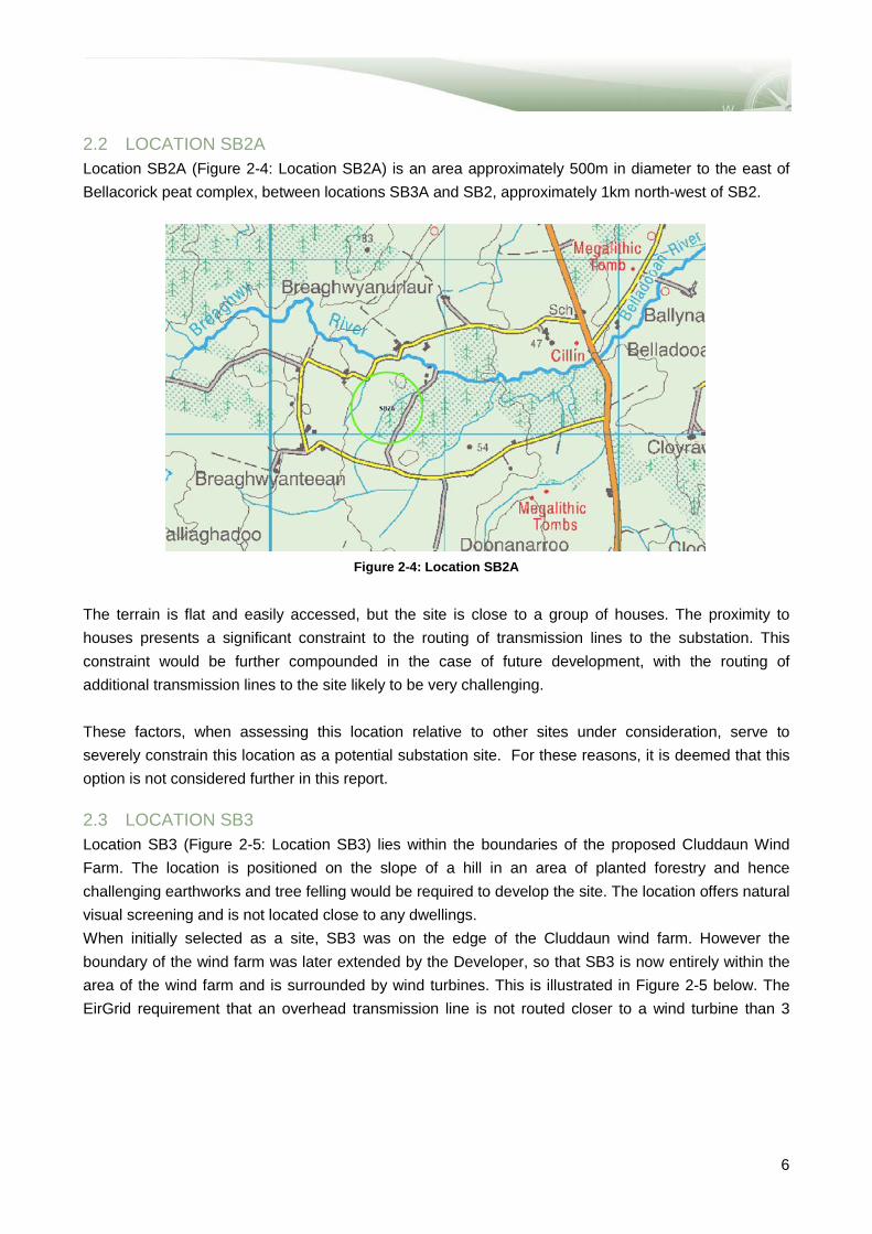
2.2 LOCATION SB2A Location SB2A (Figure 2-4: Location SB2A) is an area approximately 500m in diameter to the east of Bellacorick peat complex, between locations SB3A and SB2, approximately 1km north-west of SB2.
Figure 2-4: Location SB2A
The terrain is flat and easily accessed, but the site is close to a group of houses. The proximity to houses presents a significant constraint to the routing of transmission lines to the substation. This constraint would be further compounded in the case of future development, with the routing of additional transmission lines to the site likely to be very challenging. These factors, when assessing this location relative to other sites under consideration, serve to severely constrain this location as a potential substation site. For these reasons, it is deemed that this option is not considered further in this report. 2.3 LOCATION SB3 Location SB3 (Figure 2-5: Location SB3) lies within the boundaries of the proposed Cluddaun Wind Farm. The location is positioned on the slope of a hill in an area of planted forestry and hence challenging earthworks and tree felling would be required to develop the site. The location offers natural visual screening and is not located close to any dwellings. When initially selected as a site, SB3 was on the edge of the Cluddaun wind farm. However the boundary of the wind farm was later extended by the Developer, so that SB3 is now entirely within the area of the wind farm and is surrounded by wind turbines. This is illustrated in Figure 2-5 below. The EirGrid requirement that an overhead transmission line is not routed closer to a wind turbine than 3
6

times the wind turbine rotor diameter2 means that there are limited possible routes for an overhead line into the substation. Review of Figure 2-5 shows there is one possible route from the north and one possible route from the north-west. However the route to the north-west is over Shanettra Mountain, where the lines would be very exposed with consequent potential for significant visual impact. The route to the north is also on relatively high ground and would be visible from a great distance. In addition, in the case of future development or a substation extension, the routing of additional transmission lines to the SB3 site would be severely restricted by the wind farm layout. This restriction on the routing of lines into SB3 is very similar to that pertaining to SB1, and for the same reasons this site is not considered further in this report.
Figure 2-5: Location SB3
2.4 LOCATION SB3A Mapping showed that within the general area of location SB3A there were a number of small areas with no overlying peat. It was therefore reasonable to expect that the peat would be reasonably shallow in the immediate surrounding areas, making these sites potentially viable for the construction of a substation. However, only those areas within the locations have been considered as possible sites for the substation. The possible sites are illustrated in Figure 2-6 below.
2 This requirement is in line with standards adopted in other European countries and is imposed to prevent wake effects generated by the wind turbines causing physical oscillations in the power lines.
7

Figure 2-6: Location SB3A
2.4.1 Site SB3A – North Site SB3A-North (Figure 2-7) is a mixed peat and forest area located to the east of the Bellacorick peat complex, north-east of the existing Bellacorick substation and northwest of the SB2 area. Initial mapping showed that this site was just on the edge of the peat and at least 200m from the nearest house. However subsequent site investigation found that there is a house directly adjacent to the proposed site. Since other sites were available where this significant impact was not present, this site was not considered further in this report.
Figure 2-7: Site SB3A-North
8
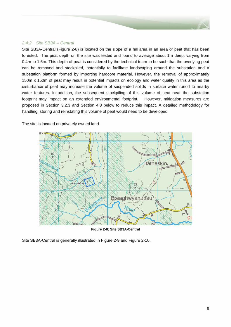
2.4.2 Site SB3A – Central Site SB3A-Central (Figure 2-8) is located on the slope of a hill area in an area of peat that has been forested. The peat depth on the site was tested and found to average about 1m deep, varying from 0.4m to 1.6m. This depth of peat is considered by the technical team to be such that the overlying peat can be removed and stockpiled, potentially to facilitate landscaping around the substation and a substation platform formed by importing hardcore material. However, the removal of approximately 150m x 150m of peat may result in potential impacts on ecology and water quality in this area as the disturbance of peat may increase the volume of suspended solids in surface water runoff to nearby water features. In addition, the subsequent stockpiling of this volume of peat near the substation footprint may impact on an extended environmental footprint. However, mitigation measures are proposed in Section 3.2.3 and Section 4.8 below to reduce this impact. A detailed methodology for handling, storing and reinstating this volume of peat would need to be developed. The site is located on privately owned land.
Figure 2-8: Site SB3A-Central
Site SB3A-Central is generally illustrated in Figure 2-9 and Figure 2-10.
9

Figure 2-9: SB3A-Central from south looking to peat
area
Figure 2-10: SB3A-Central from south looking to the
group of trees 2.4.3 Site SB3A – South Site SB3A-South (Figure 2-11) is located in a flat terrain in an area of peat on which the forest has recently been felled. Testing found that the average peat depth is about 1.6m, varying from 0.3m to 3m. This depth of peat is still considered to be such that the overlying peat can be removed and stockpiled, although the quantities involved are greater than for Site SB3A-Central and may also have an impact on ecological habitats in this area and is a pollution risk to local watercourses as a result of a possible increase in suspended solids in surface water runoff. However, mitigation measures are proposed in Section 3.2.3 and Section 4.8 below to reduce this impact.
Figure 2-11: Site SB3A-South
The site is located on land owned by Coillte and Figure 2-12 and Figure 2-13 show the views from the closest internal road (approximately 150m away).
10

Figure 2-12: SB3A-South waterlogged area
Figure 2-13: SB3A-South from north
2.5 SITE SB3B Site SB3B (Figure 2-14) is a site located to the south-east of SB3A, and north-east of SB2A, on the southern side of the Breaghwy River. It is a relatively flat area, free from peat and trees. This location would be suitable but it is located close to a group of houses, it would have been necessary to extend the 400kV line by over 2km and it would still have required significant roadworks to form a suitable access road. Given all these significant constraints, relative to other site alternatives, this site is not considered further in this report.
Figure 2-14: Site SB3B
SB3B site from the closest road is shown in Figure 2-15.
11

Figure 2-15: SB3B from south east
3 SUBSTATION EVALUATION CRITERIA 3.1 SUBSTATION EVALUATION CRITERIA The substation sites have been evaluated against each of the Substation Site Evaluation Criteria as
detailed in Table 3-1: Substation Site Evaluation Criteria. This evaluation has incorporated the
qualitative expertise of specialists to provide a reflection of whether a site or location is more or less
constrained.
The criteria selected for this report are a sub-set of the criteria used for the Stage 1 Report. A number
of the evaluation criteria used in Stage 1 have been omitted from this evaluation. As the sites brought
forward are in the same general area, the evaluation results based upon certain criteria would be the
same for all sites. The omitted criteria are as follows:
• Proximity to existing substation at Bellacorick
• Impact on length of 110kV connections to wind farms
• Impact on local infrastructure
• Location in relation to least constrained corridor
The selected criteria against which the sites have been assessed are:
• Proximity to houses
• Access
• Geotechnical conditions
• Land ownership
• Site topography
• Routing of transmission lines to substation
• Landscape and visual impact
• Ecology and
• Cultural heritage
12

Table 3-1: Substation Site Evaluation Criteria
Evaluation Criteria Considerations and comments
1 Proximity to houses / other occupied buildings: Where possible, substation sites have been located so as to be as far as practical from any housing and other buildings, to minimise the impact on local residents.
Considerations: • The number of houses potentially directly
affected by the substation development was assessed by use of postal address geo-directory data and site visits.
• Seek to avoid sites with a house closer than 200m3 from the fence line is considered
• The number of houses potentially directly affected is assessed as those being with 1km from the substation fence
2 Access - proximity to suitable public road: The development of a substation site will require the supply and delivery of the large high voltage equipment, particularly power transformers, therefore the availability of suitable roads to deliver this equipment is a key criterion for evaluation.
Considerations: • The distance from a public road. • The type and nature of that public road. • The use of that road and its proven ability to
transport large heavy loads. • The works expected to be carried out for the
construction of new access or upgrading the existing access to the substation
3 Geotechnical conditions / subsoil: Only areas which were likely to provide soil types of suitable bearing strength for the typically heavy equipment, particularly transformers, installed in substations have been considered for the substations sites to reduce the civil engineering requirement and the associated impact. For this report, substation sites in areas considered to be shallow peat have been included in the assessment. This was not the case for the Stage 1 Report. 4
Comment: • No geotechnical surveys have been carried out
at this early stage. • Ground conditions were assessed subjectively
from available mapping and site visits. • Peat probes have been taken in SB3A-Central
and SB3A-South in order to determine the depth of the peat layers.
4 Landownership: Landownership has been considered as it is advantageous to select a substation site which is either publicly owned or has a single land owner. This facilitates acquisition of the land for the substation.
Considerations: • State or private ownership of the land affects
the requirements for acquisition of the land • Sites contained within one physical boundary
were preferred e.g. within one field or paddock.
5 Topography: A substation site preferably needs to be relatively flat to avoid extensive earthworks and provide level ground necessary for the construction of substation. Thus a generally flat terrain is preferred due to reduced civil engineering requirements and associated impacts.
Comment: • Available survey mapping with 5m contours was
used to assess the topography of each site in conjunction with site visits.
6 Routing of transmission lines to substation: A new 400kV substation establishes a major new infrastructure facility, with significant capability to meet future development in the area. The substation site will need to facilitate the connection and route of the transmission lines connecting to it initially and in the future, at any voltage level as applicable. The potential for establishing routes for new transmission lines in the substation site is an important criterion.
Considerations: • Routing options for future transmission lines at
both 400kV and 110kV. • If routing not available for overhead lines,
options for routing of underground cables with associated sealing ends.
3 As a useful guide, houses within 200m from the fenceline would typically be considered to have a significant impact on amenity. 4 Following feedback received during the consultation process, potential alternative sites within the peat bog have been considered in areas where it is considered reasonably practical to overcome the constraints associated with the construction of a 400kV substation in the peat. Areas with average peat levels in excess of c. 2m are considered to be impractical.
13

Evaluation Criteria Considerations and comments
7 Landscape and visual impact: Substation sites have the potential to impact negatively on the landscape in which they are implemented, therefore the potential at each substation site to mitigate or absorb the proposed visual impact of the substation has been considered as an evaluation criterion.
Considerations: • The impact that the substation development will
have on its proposed surroundings, viewpoints, landscapes, wilderness etc.
• The opportunities to mitigate visual impact through measures such as screening, backdrops, etc.
• The visual impact of connecting overhead power lines to the substation and opportunities for mitigating the visual impact of these.
8 Ecology: Wherever ecology is impacted by the substation development, the associated impact has been considered and included within the evaluation. It should be noted that although all ecology will be reviewed, the avoidance of significant ecological constraints has been applied during the substation site identification as much as practical with the expectation that only localised constraints will be affected at this stage.
Considerations: • All known ecological constraints affected by the
substation development were assessed. Through available data and site visits
Comments: • All substation sites have been positioned away
from areas of known ecological significance.
9 Cultural Heritage: Wherever cultural heritage is impacted by the substation development, the associated impact has been considered and included within the evaluation. It should be noted that although all cultural heritage will be reviewed, significant cultural heritage constraints have been avoided during the substation site identification as much as practical with the expectation that only localised constraints will be affected at this evaluation stage.
Considerations: • Location of all known cultural heritage
potentially impacted by the substation developments.
Comments: • Due to the compact nature of the substation
sites the primary cultural heritage constraints have been avoided where possible.
3.2 COMMENTS ON EVALUATION CRITERIA In evaluating the alternative sites against the evaluation criteria set out above, several of the criteria have greater significance at this stage of the development process and taking into account that all the sites are in generally the same area. These criteria are
• Proximity to houses • Access to the sites • Geotechnical conditions • Land ownership.
These have typically been the drivers for the investigation into these alternatives sites and/or the selection of the sites. The major considerations in assessing these criteria are discussed in more detail below. 3.2.1 Proximity to Houses EirGrid’s policy is to maintain the greatest practical distance between high voltage substations and housing, always taking into account EirGrid’s obligation to provide a ‘safe, secure, reliable, economical and efficient transmission system. As a useful guide, houses within 200m from the fenceline would typically be considered to have a significant impact on amenity. The evaluation of the sites in this report subjectively considers the proximity of each site to housing, taking into account the number of houses within a distance of 1km from the substation site, and then how close each individual house is to the site.
14

3.2.2 Access to Site One very important consideration for deciding on the location of a substation is access to the site. The power transformers (or grid transformers) in particular are very large and heavy items of equipment that need to be transported as abnormal loads, technically known as ‘Abnormal Indivisible Loads’ (AIL). For this project, it is currently proposed that the grid transformer will be a 500MVA 400kV/110kV transformer. Indicative weights for a transformer of this rating have been obtained from a number of international transformer manufacturers5 and are set out in Table 3-2 below. Manufacturer Rating Installed Weight Transport Weight Shipping
Dimensions (l-w-h) Metres
Siemens 500MVA 400/110kV - 160 tonnes 9.8 x 3.8 x 4.8 Alstom 500MVA 415/145kV 328 tonnes 221 tonnes 10 x 4 x 4.5 Hyosung 550MVA 415/275kV - 210 tonnes 9.5 x 4 x 4.5 Proposed for Coolnabacky Substation6
500MVA 400/110kV - 222 tonnes 8.4 x 3.6 x 4.5
Table 3-2: Summary of Indicative Transformer Shipping Parameters Review of the above table demonstrates that there is a range in both transport weights and dimensions. The transport weight indicated by Siemens is lower than expected and therefore for the initial assessment at this stage of the project a transport weight of approximately 220 tonnes has been assumed, with shipping dimensions of 10m x 4m x 4.8m. An Indicative Heavy Haulage Route Assessment has been carried out for the Grid West project. The main findings can be summarised as follows:
• The most recent example of an AIL being transported into the northern Co Mayo area was the Tunnel Boring Machine used on the Corrib On-Shore Gas Pipeline project. This unit weighed 170 tonnes and was transported on the N59 through Crossmolina.
• A report for the Laois – Kilkenny Reinforcement Project - EirGrid 400/110kV Transformer; Proposed Haulage Route Assessment, consider the haul route for a 400/110kV transformer, similar to that proposed for Grid West from Dublin Port to Coolnabacky, Co Laois
• The height of the proposed Grid West transformer and the profile of the road, particularly the R315 from Crossmolina, mean that it will probably be necessary to use a girder trailer for transporting the transformer.
5 In some cases the manufacturers did not have the details for the exact transformer, but have supplied details for the nearest similar transformer that they have supplied 6 Laois – Kilkenny Reinforcement Project - EirGrid 400/110kV Transformer; Proposed Haulage Route Assessment (Revision 2 dated 06.08.2013).
15

• For the purpose of this report it is proposed that the transformer would be shipped through Dublin Port. Other ports should be investigated when the final transport plan is developed.
• Subject to a detailed study once the final dimensions of the transformer are available, the route from Dublin would be as follows: a) Via East Wall Road (see section 3.2.1 for further details); b) the M50, c) N4 approaches to the M4 and the motorway itself, d) the national Primary Route N4 in dual carriageway to Mullingar and single carriageway to
Longford; e) Continuing along N4 onto Carrick on Shannon, Boyle, Collooney and Ballysadare (south of
Sligo Town); f) the National Secondary Route N59 from Ballysadare to Ballina and onto Crossmolina; g) The R315 and local county road network to the proposed substation site.
• There are a number of constraints along the route. However for the majority of constraints the remedial action that would be required will include the temporary removal of signs, traffic signal poles and other street furniture as well as temporary closing of roads / junctions.
• The R315 presents a number of constraints in the form of old stone arch bridges of uncertain load-bearing capacity, sharp bends and poor vertical alignment. It is likely that these constraints can be overcome by road improvement works and that the vertical alignment will necessitate a realignment of the road, to the benefit of all road users.
• The local road access off the R315 to the different substation sites are all inadequate and will have to be reconstructed to a suitable standard. This is discussed further below.
• It is considered that it will be reasonably practical to transport the transformer to the vicinity of the substation sites under consideration.
In the vicinity of the potential substation sites considered in this report, there are a number of options for accessing the individual sites/locations, using local roads off the R315. These options are discussed in more detail in Appendix C. However the main findings can be summarised as follows:
• None of the local roads off the R315 are currently suitable for construction or AIL transport. All are structurally unsuitable, too narrow with unsuitable horizontal and vertical alignment.
• Five different local roads have been considered for potential upgrade, designated as Roads A – E. These are illustrated in Figure 3-1. Table 3-3 summarises the potential requirements for upgrading these roads.
• The upgrading of the local roads would benefit local residents and users through the provision of a greatly improved road.
16

Figure 3-1: Local Road Access to Substation Sites
Provides access to Length
km Evaluation Notes
Road A SB3A–Central, SB3A-South 3.40 Several bridges/culverts
Road B SB3A–Central, SB3A-South 2.70 Several sharp bends plus river crossing
Road C SB2; 1.60 One river crossing, sharp bend requires
realignment of road SB3A–Central, SB3A-South 3.20 Road D SB2 1.00
Road E SB2 2.36
Table 3-3: Summary of Local Road Upgrades
Following the initial identification of the SB3A sites, information was sought from the developers of the Oweninny and Cluddaun wind farms, with regards to the possibility of using a proposed wind farm haul
Less Preferred More Preferred
17

road from the N59, close to the Bellacorick substation, through both wind farms to a point close to SB3A. This road would be suitable for transport of the abnormal loads required for the wind farms and consideration should be given to upgrading it to allow the transport of the heavier substation transformer. However, following a meeting with the developers of the Oweninny wind farm, it became clear that this road was unlikely to be constructed until the Grid West project was at least in construction, and therefore the Grid West project could not rely on this road being available. 3.2.3 Geotechnical conditions / subsoil As set out in the Introduction, initially substation sites in the peat bog were not considered because of access difficulties, construction difficulties and potential impact on the sensitive environment. However it is possible to construct a substation in shallow peat. The purpose of this section is to outline the requirements for doing so as this forms an essential part in understanding the evaluation process. The ground generally slopes downwards in an easterly direction. However there appears to be significant areas of level ground which appear to be heavily saturated, particularly around sites SB3A-Central and SB3A-South. Once an agreed substation location is decided upon a topographical survey will be required to determine existing levels, tracks, ditches, watercourses etc. There is insufficient information at present to provide a detailed analysis of the underlying geology but based on survey information7 available as a desk study, the following summary can be provided:
• There is glacial till across the majority of the SB3A site • Peat is located generally in the western part of the area and does impact sites SB3A-Central
and SB3A-South. A Peat Probing exercise was carried out at Sites SB3A-Central and SB3A-South and found layers of peat ranging between 0.3m and 3m in depth.
• The solid geology beneath the eastern part of the site (SB2) comprises rock belonging to the Dinantian (early) Sandstones, Shales and Limestones.
• Historical maps indicate the presence of lime kilns running east to west; however there does not appear to be any sign of lime quarries in the general area. This would suggest that limestone may have been extracted via underground workings.
Further detailed site investigation works will be required once a substation site has been agreed to determine the exact composition of the underlying soil conditions and suitability for cut and fill. As indicated above, the sites within SB3A are on part shallow peat land. If a substation were to be constructed on either SB3A-Central or SB3A-South the following would be necessary to deal with the peat overlying the sites:
7 Geological Survey of Ireland
18

• The peat would need to be removed over the whole substation area down to the underlying solid ground. The peat would need to be excavated over an area of at least 150m x 150m. For SB3A-Central where the average depth is about 1m, this means a total of approximately 22,500m3 would have to be excavated. For SB3A-South this amount would be approximately 32,000m3. These are still significant quantities involving a major excavation and a large number of truck movements.
• This peat would need to be separated into Acrotelmic and Catotlemic8 peat, with the latter being stored around the site to a height of 1m-2m, requiring a further area of at least 20,000m2. The Arcotelmic surface peat would be used for reinstating disturbed peat and covering the stockpiled stored peat. This peat could be used to landscape around the substation and provide some visual screening. This technique has been used successfully in Scotland where substations have been built in areas of peat.
• A substation platform would then need to be formed using cut and fill material where suitable imported quarried material. The platform would have to be sufficiently built up above the underlying ground to allow the platform to be properly drained to avoid pluvial flooding. Detailed engineering will be needed to design this platform but normal practice requires a minimum depth to formation below platform level of 1m. This would require cut and fill or imported material, depending on the underlying ground conditions. This depth may be greater on SB3A-South which is lower lying and flatter, requiring a higher platform to avoid pluvial flood levels.
The area of SB2 is generally much better ground, requiring only the normal earthworks associated with the construction of any substation, involving site levelling, platform formation (using imported material), drainage and then surfacing. Table 3-4 below compares the various sites from geotechnical conditions and subsoil prospective. .
8 Acrotelmic and Catotlemic peat are two distinct layers in undisturbed peat bogs. The acrotelm overlies the catotelm, The boundary between the two layers is defined by the transition from peat containing living plants (acrotelm) to peat containing dead plant material (catotelm). This typically coincides with the lowest level of the water table. Fluctuations in water table in a peat bog occur within the acrotelm, and hence conditions may vary from aerobic to anaerobic with time.
19

Table 3-4: Summary of Site Geotechnical Conditions
Site Ground Conditions Water Courses SW Drainage SB2 Site SB2 is situated approximately
800m to the west of the R315 and is located in farmland. No SI or Peat Probe information is available at present however a lime kiln was noted in historical maps just to the south of the proposed site. The Peat Area map does not indicate any peat deposits within the SB2 area
There is conflicting information as to the nature of existing drainage systems in this area. Google Maps indicates a watercourse approximately 350m to the south of the site with the Dunowen River a further 700m to the south. Ordnance Survey Ireland only indicates a series of ditches in this area with the majority appearing to discharge south into the Dunowen River. Further topographical information will be required to determine the position and direction of flow of the existing drainage systems prior to finalising drainage design.
Surface water drainage from the site would discharge into the existing ditch system; however topographical survey information will be required to determine the most suitable discharge points. Attenuation ponds will possibly be required to reduce flows to the current greenfield run-off rate. Foul drainage would discharge into a suitably sized septic tank.
SB3A-Central
The site has been forested with approximately 50% of the trees recently felled. A Peat Probe investigation was carried out in November 2013 where it was found that peat depths of 0.4m to 1.6m were encountered with an average peat depth of 1m. There are a series of drainage ditches present with a triangular shaped pond evident to the south of the Ballinglen River.
The Ballinglen River is situated approximately 60m to the north of the site and flows in a north easterly direction. A series of man-made ditches are visible as is a triangular shaped pond between the river and a forestry track to the south. The ditches appear to discharge in a northerly direction into the Ballinglen River. Approximately 450m to the south of the site the Breaghwhy River flows in an easterly direction. There are only isolated ditches visible in this area
Surface water drainage from the site would likely follow the flow of the existing ditches i.e. in a northerly direction discharging into the Ballinglen River. Attenuation ponds will possibly be required to reduce flows to the current greenfield run-off rate. Foul drainage would discharge into a suitably sized septic tank.
SB3A-South
Site SB3A-South is approximately 400m south of Site SB3A-Central. The site has been forested with approximately 50% of the trees recently felled. A Peat Probe investigation was carried out in December 2013 where it was found that peat to depths of 0.3m to 3m was encountered with an average peat depth of 1.4m.
The Ballinglen River is situated approximately 180m to the north of the site and flows in a north easterly direction. A series of man-made ditches are visible and a triangular shaped pond between the river and a forestry track to the south. The ditches appear to discharge in a northerly direction into the Ballinglen River. Approximately 180m to the south east of the site the Breaghwy River flows in an easterly direction. There are only isolated ditches visible in this area
Surface water drainage from the site would likely follow the flow in a southerly direction discharging into the Breaghwy River. Attenuation ponds will possibly be required to reduce flows to the current greenfield run-off rate. Foul drainage would discharge into a suitably sized septic tank.
3.2.4 Landownership Site SB3A-South is on land owned by Coillte with other sites located on privately owned land.
20

4 EVALUATION OF SUBSTATION SITES In this section of the report, sites SB3-Central, SB3-South and location SB2 will be assessed against each of the criteria set out in Section 3.
Figure 4-1: Map showing locations SB3A and SB2
21
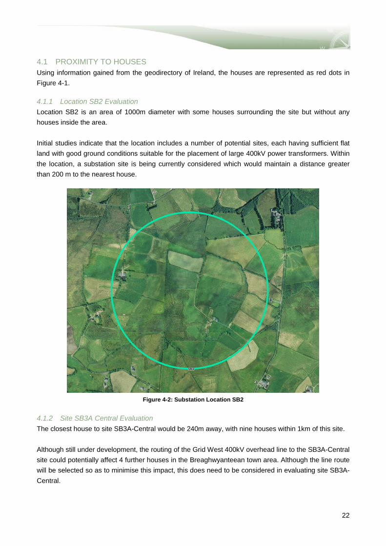
4.1 PROXIMITY TO HOUSES Using information gained from the geodirectory of Ireland, the houses are represented as red dots in Figure 4-1. 4.1.1 Location SB2 Evaluation Location SB2 is an area of 1000m diameter with some houses surrounding the site but without any houses inside the area. Initial studies indicate that the location includes a number of potential sites, each having sufficient flat land with good ground conditions suitable for the placement of large 400kV power transformers. Within the location, a substation site is being currently considered which would maintain a distance greater than 200 m to the nearest house.
Figure 4-2: Substation Location SB2
4.1.2 Site SB3A Central Evaluation The closest house to site SB3A-Central would be 240m away, with nine houses within 1km of this site. Although still under development, the routing of the Grid West 400kV overhead line to the SB3A-Central site could potentially affect 4 further houses in the Breaghwyanteean town area. Although the line route will be selected so as to minimise this impact, this does need to be considered in evaluating site SB3A-Central.
22

The location of the site and its orientation make this site suitable in terms of routing future overhead lines or underground cables. 4.1.3 Site SB3A South Evaluation The closest house to SB3A-South is located 560m away, with 9 houses in the Breaghwyanteean town and one house located 960m to the north side, meaning 11 houses in total affected within 1km area. Although still under development the routing of the Grid West 400kV overhead line to the SB3A-Central could potentially affect 3 further houses in the Breaghwyanteean town area. Although the line route will be selected so as to minimise this impact, this does need to be considered in evaluating site SB3A-South. The location of the site and its orientation make this site suitable in terms of routing future overhead lines. 4.1.4 Conclusion - Proximity to Houses Consideration of the proximity to the different houses set out for each of the sites above shows that each has different advantages and disadvantages. SB3A-South impacts on a higher number of houses, but SB3A-Central is closer to a house than for either of the other alternatives. SB3A-South and SB2 both impact on a number of houses but most of these houses are over 750m from the site, where the impact the impact is significantly less. However in the case of SB2 the houses tend to surround the potential sites on all sides, making the impact greater than for SB3A-South, where selected screening could be used to significantly reduce the visual impact. However the additional length of 400kV overhead line to the SB3A sites will impact on a number of houses in addition to the impact of the substation itself. It is therefore considered that of these two sites SB2 has slightly greater impact than SB3A-South. With the one close house to SB3A-Central, this site has a similar overall proximity to houses as the SB3A-South site. Table 4-1: Proximity to Houses Evaluation Matrix
Evaluation criteria SB2 SB3AC SB3AS
Proximity to houses
4.2 ACCESS 4.2.1 Location SB2 Evaluation SB2 is accessible via a short length of local road (approximately 1km), off the R315 from either the southern side or the northern side (Road C or D as set out in Section 3.2.2). The selection of the access road would be determined by the final site selection. This access is illustrated in Figure 4-3 below.
Less Preferred More Preferred
23

Either local road would have to be upgraded to make it suitable for access to the site (refer to Section 3.2.2) but upgrade of Road C would have greater benefit to the local community.
Figure 4-3: Access to location SB2
4.2.2 Sites SB3A Central and South Evaluation SB3A-Central and SB3A-South are located relatively close together and hence the access to both sites would be similar. As discussed in Section 3, the ‘haul road’ through the wind farms was considered but it was found that it would be not be constructed in time and therefore could not be used for access to site in the construction of the Grid West project. There is no local public road to either site, but there are some forestry tracks that come close to both sites. As reported in Section 3, there are a number of local roads off the R315 that could be upgraded to form the access road to the two sites. Further work is necessary to determine the best of these routes but there is no doubt that an engineering solution could be achieved, although at some cost. The other issue would be securing the additional rights of way required to widen the road from the affected landowners.
Road C
Road D
24

4.2.3 Conclusion - Access In terms of access SB2 has a clear advantage over the two SB3A sites. Being closer to the R315 not only is the cost of providing the final section of access road significantly lower, the overall cost of the project is lower since it is not necessary to extend the 400kV transmission line the additional 2.5 to 3km. Table 4-2: Access Matrix
Evaluation criteria SB2 SB3AC SB3AS
Access
4.3 GROUND CONDITIONS Comprehensive geotechnical surveys have not been carried out at this stage and ground conditions have been assessed subjectively from available mapping and site visits. Geological survey maps of the area indicate that the sites are in an area with Dinantian (early) Sandstones, Shales and Limestones. 4.3.1 Location SB2 Evaluation Desk top investigation of the ground conditions coupled with a site visit indicate that SB2 is suitable for the location of the substation. Areas of cutover peat have been identified to the south of the site but are localised and can be avoided. The easterly location of this site within the study area will reduce the requirement to position 400kV towers within the Bellacorick peat complex. However, additional 110kV towers or poles and/or underground cables will be required to connect to the existing 110kV network and the wind farms. 4.3.2 Site SB3A-Central Evaluation A site investigation was carried out to assess the ground conditions and, in particular, the depths of peat in SB3A-Central. This report can be found in Appendix E, where the probes show that the peat depth varies from 0.4m to 1.6m, with an average depth of about 1m. Hence, in SB3A-Central, a peat storage area would be required in order to accommodate 22,500m3 of peat (considering peat 1m deep and the site being 150m x 150m). 4.3.3 Site SB3A-South Evaluation A site investigation was carried out to assess the ground conditions and in particular the depths of peat in SB3A-South. It was found that the peat depth varies from 0.3m to 3m, with an average depth of about 1.4m. Hence in SB3A-Central a peat storage area would be required in order to accommodate approximately 32,000m3 of peat (considering peat 1.4m depth and the site being 150m x 150m). Adjacent to the northern boundary of the site there is a 20m wide area classified by the project ecologist as an important habitat , a linear strip of deciduous woodland dominated by Willow with birch species
Less Preferred More Preferred
25
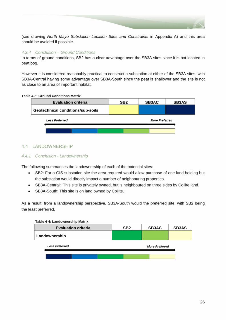
(see drawing North Mayo Substation Location Sites and Constraints in Appendix A) and this area should be avoided if possible. 4.3.4 Conclusion – Ground Conditions In terms of ground conditions, SB2 has a clear advantage over the SB3A sites since it is not located in peat bog. However it is considered reasonably practical to construct a substation at either of the SB3A sites, with SB3A-Central having some advantage over SB3A-South since the peat is shallower and the site is not as close to an area of important habitat. Table 4-3: Ground Conditions Matrix
Evaluation criteria SB2 SB3AC SB3AS
Geotechnical conditions/sub-soils
4.4 LANDOWNERSHIP 4.4.1 Conclusion - Landownership The following summarises the landownership of each of the potential sites:
• SB2: For a GIS substation site the area required would allow purchase of one land holding but the substation would directly impact a number of neighbouring properties.
• SB3A-Central: This site is privately owned, but is neighboured on three sides by Coillte land. • SB3A-South: This site is on land owned by Coillte.
As a result, from a landownership perspective, SB3A-South would the preferred site, with SB2 being the least preferred.
Table 4-4: Landownership Matrix
Evaluation criteria SB2 SB3AC SB3AS
Landownership
Less Preferred More Preferred
Less Preferred More Preferred
26
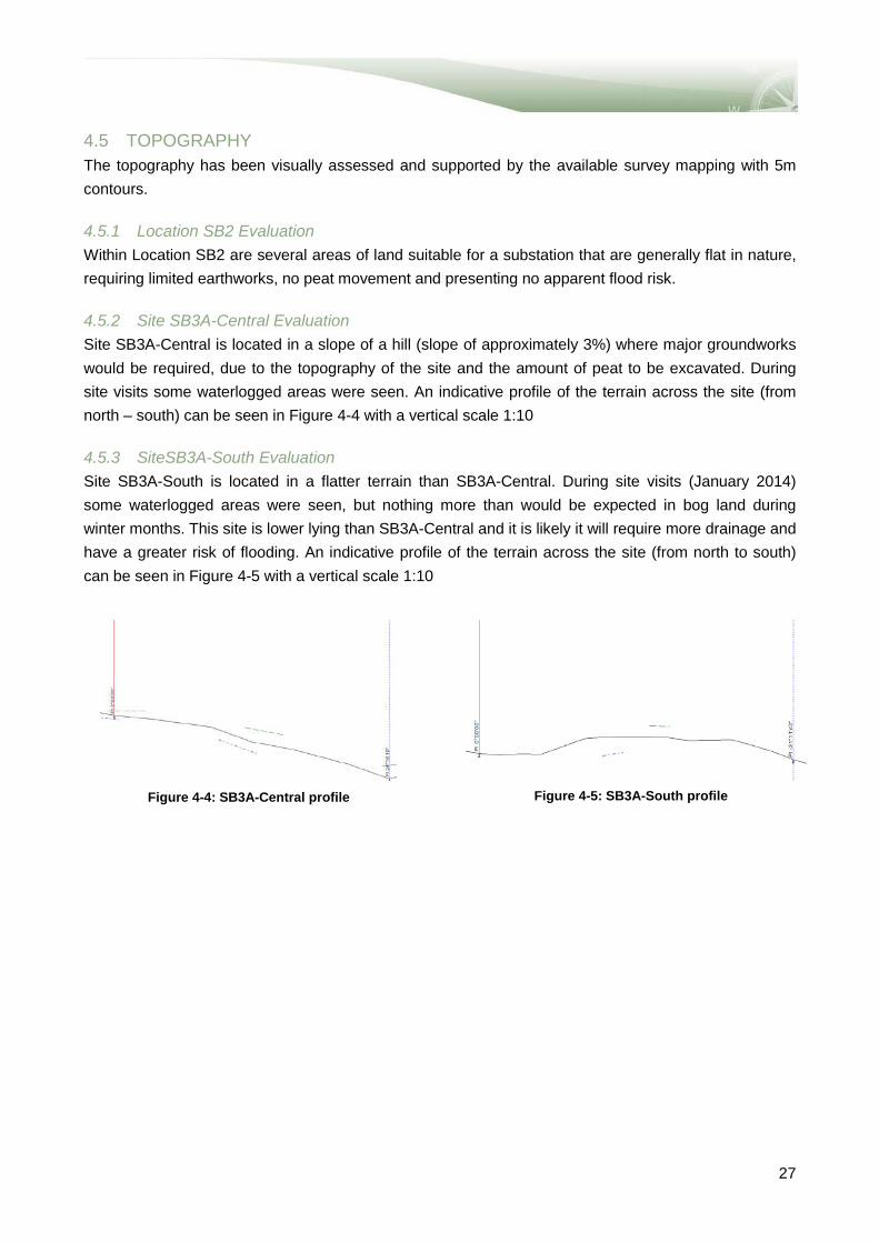
4.5 TOPOGRAPHY The topography has been visually assessed and supported by the available survey mapping with 5m contours. 4.5.1 Location SB2 Evaluation Within Location SB2 are several areas of land suitable for a substation that are generally flat in nature, requiring limited earthworks, no peat movement and presenting no apparent flood risk. 4.5.2 Site SB3A-Central Evaluation Site SB3A-Central is located in a slope of a hill (slope of approximately 3%) where major groundworks would be required, due to the topography of the site and the amount of peat to be excavated. During site visits some waterlogged areas were seen. An indicative profile of the terrain across the site (from north – south) can be seen in Figure 4-4 with a vertical scale 1:10 4.5.3 SiteSB3A-South Evaluation Site SB3A-South is located in a flatter terrain than SB3A-Central. During site visits (January 2014) some waterlogged areas were seen, but nothing more than would be expected in bog land during winter months. This site is lower lying than SB3A-Central and it is likely it will require more drainage and have a greater risk of flooding. An indicative profile of the terrain across the site (from north to south) can be seen in Figure 4-5 with a vertical scale 1:10
Figure 4-4: SB3A-Central profile
Figure 4-5: SB3A-South profile
27

4.5.4 Conclusion - Topography Of the three sites, location SB2 has the preferred topography for the construction of a substation. It is the flattest land and has little risk of flooding. Of the two sites in SB3A, the flat nature of SB3A-South makes it preferable to SB3A-Central, but the sloping profile of SB3A-Central can be used to a positive advantage to allow an effective drainage system to be provided.
Table 4-5: Topography Evaluation Matrix
Evaluation criteria SB2 SB3AC SB3AS
Topography
4.6 ROUTING OF TRANSMISSION LINES TO SUBSTATION 4.6.1 Location SB2 Evaluation Location SB2 would allow future 110kV and 400kV transmission lines to be routed to the substation. As there are houses surrounding the location in all directions, the routing of future transmission lines at both 400kV and 110kV would be more constrained than for the SB3A sites. In order to mitigate this impact, it has been agreed that all the 110kV circuits routed into the new substation will be installed underground for at least 2km. 4.6.2 Site SB3A Central and South Evaluation SB3A-Central and SB3A-South are located in open space away from the houses, where the flexibility to route new transmission lines is greater than for SB2. Of the two sites, SB3A-South is closer to a concentration of houses and is therefore marginally less preferred than SB3A-Central. However as it is proposed that the 110kV lines will be routed underground for the first 2km from the new substation, the impact of this routing for SB2 is reduced. 4.6.3 Conclusion – Routing of Transmission Lines The table below reflects the evaluation of the three sites described above. Table 4-6: Routing of transmission lines to substation Matrix
Evaluation criteria SB2 SB3AC SB3AS Routing of transmission lines to substation
Less Preferred More Preferred
Less Preferred More Preferred
28

4.7 LANDSCAPE AND VISUAL IMPACT 4.7.1 Location SB2 Evaluation SB2 is located over 3km North West of the village of Moygownagh in the townland of Doonanarroo. The landform is relatively flat and open with a predominance of small scale pastures. Travelling along the R135 from the south, views open up north of the townland of Garranard. There are occasional panoramic views across an open pastoral landscape that is characterised by rough grassland fields, with fragmented hedgerow field boundaries. In the townlands of west of Carnclogh mid to far distance views to the north towards the proposed SB2 will only be intermittent, and screened in the majority of locations due to the mainly flat landform and the patchy vegetation cover. There are individual deciduous and evergreen trees which intermittently limit views towards the proposed substation SB2. The patchy scrub and tree cover in the immediate vicinity of the proposed SB2 substation provides some screening of the site. The proposed SB2 substation will not be widely visible from locations to the south (west of Garranard) due to the nature of the topography obscuring long distance views. From the local road to the north of the site, mid distance views across the landscape are possible. Further north, views of the substation would be obscured by forestry land along this local access road. The addition of overhead lines would be clearly visible in open areas of the pastoral landscape west of the R315. Existing overhead lines along access roads are screened from view by the roadside vegetation and therefore there would be no significant cumulative visual effects. 4.7.2 Site SB3A Central Evaluation Site SB3A-Central is located on slightly sloping land which is characterised by peat land which has been encroached by forestry. The landscape exhibits a pattern of bog, moorland and conifer plantation. The presence of forestry in the area reduces the character of wilderness. Due to the sloping landform and the intervening patches of vegetation, the proposed substation will not be visible from the R315 to the west. Similarly, from local access roads in the vicinity to the north of the proposed site, views to the substation will not be possible due to the mix of deciduous and evergreen tree cover. However, there are areas to the west of Glenedagh, to the north west of the proposed SB3A Central site, where the landscape has a more open quality and characteristics of wilderness. Due to the presence of woodland in the vicinity of the substation site, and the local undulations in the area, the proposed development will be screened from view from all sides. Due to the sloping, undulating landform and the patches of commercial forestry in the area, the connecting overhead power lines will be well screened by the enclosing nature of the landscape. 4.7.3 Site SB3A South Evaluation Travelling along the local road in the Breaghwyanteean area views are enclosed, although visibility opens up to the north west of this townland. Views to the mid distance are of a flat, open pastoral landscape with occasional patches of forestry limiting extensive views to the far distance. Where there are gaps in forestry cover, views will be possible of the SB3A South substation in the near distance in close proximity to the access road.
29

From locations to the north of this proposed substation, views will generally be obscured due to the convex, sloping landform and prevalent commercial forestry throughout the area. The addition of connecting overhead power lines to SB3A-Central will add a visible new element to the relatively flat and open Breaghwyanurlaur River landform. As commercial forestry is less extensive than on upper slopes and given that there are overhead lines present in the wider landscape to the south east, the addition of further overhead lines will result in cumulative visual effects. 4.7.4 Conclusion – Landscape and Visual SB3A-Central is located on relatively elevated sloping land, with areas of commercial forestry and occasional patches of scrub and tree clumps obscuring the substation from view. The sloping landform limits any views of this proposed substation. Additionally, the topography and land cover of this area will screen the connecting power lines. SBA-South is in a similar location, albeit at a lower elevation close to the Breaghwy River. It is closer to the townland and individual settlements of Breaghwyanteean. Consequently, it would be closer and therefore more visible than SBSA-Central. The vegetation cover in the vicinity of SB2 will screen the substation from many viewpoints. Due to the flatter, open landform, the proximity to the R315 and other roads some open views are possible. However the site offers good potential for vegetation establishment to provide screening of the site over time. The location of SB2 is on lower land and in a landscape with less wilderness characteristics than the upper slopes of SB3A-Central and SB3A-South. However it is the closest site to visual receptors. Table 4-7: Landscape and visual impact Matrix
Evaluation criteria SB2 SB3AC SB3AS
Landscape and visual impact
4.8 ECOLOGY 4.8.1 Location SB2 This site was not assessed from the field due to access restrictions. Assessment of site suitability is therefore desk based only. The site appears to consist largely of a mix of wet and improved grassland and is actively farmed. It is located on flat sloping land, criss-crossed by drainage ditches draining into the Cloonaghmere River. Potential ecological receptors include:
• Hedgerow boundaries • Watercourses to the north and south, and • Some fields consist of wet grassland in particular close to the river (mostly recently afforested).
There is scope for locating a substation while minimising ecology impacts. This site would be favourable in an ecology based comparative analysis.
Less Preferred More Preferred
30

4.8.2 Site SB3A-Central The proposed location is on conifer plantation which has been felled and recently replanted (approximately within last 10 years). The conifer plantation has been planted on peatland habitat (upland raised bog habitat). The site is criss-crossed by drainage channels dug to increase drainage for forest crop. The site is located on top of a slope with drainage like to run north and/or south. The Gleneadagh River is located c. 0.16km to the north; however the southern section of the site drains south and along an unplanted strip which was observed to behave like a watercourse on the day of the site visit (20.01.14). There is scope for locating a substation while minimising ecology impacts. This site would be favourable in an ecology based comparative analysis, although the impact on a significant area of peat makes the location less suitable than SB2. 4.8.3 Site SB3A-South The southern plot is located on conifer plantation of two different age stages. The western section has been recently replanted and consists of Larch and pine plantation, planted within approximately the last 5-7 years. The eastern section is older (approximately 10-15 years) and consists of a spruce and pine mix. Both plantations are located within upland peatland habitat (similar to SB3A). Artificial drainage criss-crosses the site increasing the rate of surface water run-off. A regenerating cutover peat land is located to the south however any further disturbance (including drainage) may impact upon this habitat. A linear strip of deciduous woodland dominated by Willow with birch species also present is located along the northern boundary. This strip is approximately 20m wide in sections and is of high local importance, acting to increase diversity within the upland peat land/conifer plantation landscape. It is recommended that this woodland strip be retained if possible. The Breaghwy River is located approximately 0.15km south of the site however a large section of the site appears to follow site topography which slopes to the north. There is scope for locating a substation while reducing ecology impacts through the avoidance of deciduous woodland on the northern boundary. 4.8.4 Conclusion - Ecology The matrix below reflects the evaluation described above. Table 4-8: Ecology Matrix
Evaluation criteria SB2 SB3AC SB3AS
Ecology
Less Preferred More Preferred
31

4.9 CULTURAL HERITAGE 4.9.1 Substation SB2 Evaluation There is one megalith located within this identified substation location and a second just outside the identified substation to the North West (MA21:28 & 029) – both were inaccessible so it is not possible to say how well preserved they are. These sites however are unlikely to be close to the substation site because of housing in the proximity. There would be an impact on the setting of these sites (although without a site inspection it is difficult to say with certainty what the level of this impact would be). The proposed 400kV line would be shorter if this option was selected and there would be no impact on the setting of a mound located further west (MA021:023). 4.9.2 Substation SB3A-Central and SB3A-South Evaluation There are no cultural heritage constraints in the immediate vicinity. However, the proposed line route would pass in the vicinity of an impressive mound feature (MA021:023) which has good views to the south. None of the proposed substations would likely be visible from this mound. There would be an impact on the setting of the mound as a result of the construction of the towers. Careful line design at this location could mitigate the impact on the setting of this monument. If this is done, either substation SB3A-Central or SB3A-South would be preferable from a cultural heritage point of view. 4.9.3 Conclusion – Cultural Heritage With appropriate line design either substation SB3A-Central or SB3A-South would be preferable to SB2 from a cultural heritage point of view. However, if it is not possible to avoid mound MA021:023 and there is a resultant impact on the setting of the mound, then SB2 would be preferable (the scores below would be reversed). Table 4-9: Cultural Heritage Matrix
Evaluation criteria SB2 SB3AC SB3AS
Cultural Heritage
(Subject to line route avoiding impact to mound)
Less Preferred More Preferred
32
5 CONCLUSION
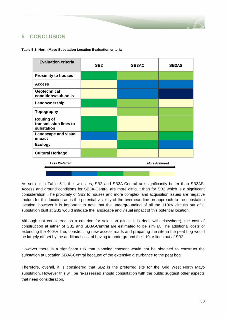
Table 5-1: North Mayo Substation Location Evaluation criteria
Evaluation criteria
SB2 SB3AC SB3AS
Proximity to houses
Access Geotechnical conditions/sub-soils
Landownership
Topography Routing of transmission lines to substation Landscape and visual impact
Ecology
Cultural Heritage
As set out in Table 5-1, the two sites, SB2 and SB3A-Central are significantly better than SB3AS. Access and ground conditions for SB3A-Central are more difficult than for SB2 which is a significant consideration. The proximity of SB2 to houses and more complex land acquisition issues are negative factors for this location as is the potential visibility of the overhead line on approach to the substation location; however it is important to note that the undergrounding of all the 110kV circuits out of a substation built at SB2 would mitigate the landscape and visual impact of this potential location. Although not considered as a criterion for selection (since it is dealt with elsewhere), the cost of construction at either of SB2 and SB3A-Central are estimated to be similar. The additional costs of extending the 400kV line, constructing new access roads and preparing the site in the peat bog would be largely off-set by the additional cost of having to underground the 110kV lines out of SB2. However there is a significant risk that planning consent would not be obtained to construct the substation at Location SB3A-Central because of the extensive disturbance to the peat bog. Therefore, overall, it is considered that SB2 is the preferred site for the Grid West North Mayo substation. However this will be re-assessed should consultation with the public suggest other aspects that need consideration.
Less Preferred More Preferred
33


APPENDICES


APPENDIX A: SUBSTATION SITES DRAWING
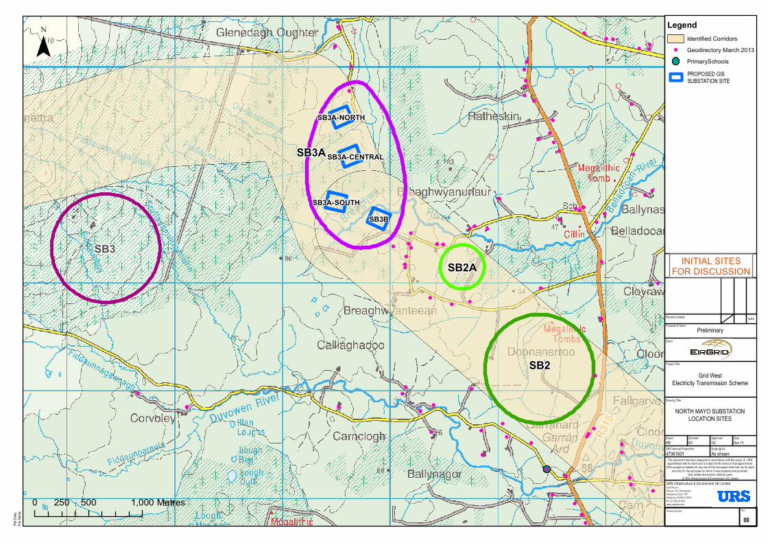
SB2
SB3A
SB2A
SB3B
SB3A-CENTRAL
SB3A-SOUTH
SB3A-NORTH
SB3
Purpose of Issue
Project Title
Drawing Title
Drawn Checked
NORTH MAYO SUBSTATIONLOCATION SITES
Grid WestElectricity Transmission Scheme
Scott HouseAlençon Link, BasingstokeHampshire, RG21 7PPTelephone (01256) 310200Fax (01256) 310201www.ursglobal .com
URS Infrastructure & Environment UK Limited
DateApproved
Drawing Number
This document has been prepared in accordance with the scope of URS'appointment with its client and is subject to the terms of that appointment.
URS accepts no liability for any use of this document other than by its clientand only for the purposes for which it was prepared and provided.
Only written dimensions shall be used.© URS Infrastructure & Environment UK Limited
URS Internal Project No. Scale @ A347061601 As shownMB GC GC Dec 14
Suffix
PreliminaryClient
Revision Details
Plot D
ate:
File Na
me:
¯
Rev
00
0 500 1,000250 Metres
¯
INITIAL SITESFOR DISCUSSION
PROPOSED GISSUBSTATION SITE
LegendIdentified CorridorsGeodirectory March 2013PrimarySchools

!
!
!
!
!
!
!
!
!
!
!
!
!
SB2
SB3A
SB2A
SB3B
SB3A-CENTRAL
SB3A-SOUTH
SB3A-NORTH
SB3
Purpose of Issue
Project Title
Drawing Title
Drawn Checked
NORTH MAYO SUBSTATIONLOCATION SITES AND
CONSTRAINTS
Grid WestElectricity Transmission Scheme
Scott HouseAlençon Link, BasingstokeHampshire, RG21 7PPTelephone (01256) 310200Fax (01256) 310201www.ursglobal .com
URS Infrastructure & Environment UK Limited
DateApproved
Drawing Number
This document has been prepared in accordance with the scope of URS'appointment with its client and is subject to the terms of that appointment.
URS accepts no liability for any use of this document other than by its clientand only for the purposes for which it was prepared and provided.
Only written dimensions shall be used.© URS Infrastructure & Environment UK Limited
URS Internal Project No. Scale @ A347061601 As shownMB GC GC Dec 14
Suffix
PreliminaryClient
Revision Details
Plot D
ate:
File Na
me:
¯
Rev
00
0 500 1,000250 Metres
¯
INITIAL SITESFOR DISCUSSION
PROPOSED GISSUBSTATION SITE
Legend! Cluddaun Windfarm
Geodirectory March 2013PrimarySchoolsSACBlanket PeatFen PeatCut / Cutover PeatBedrockKarstified Rock


APPENDIX B: INDICATIVE SUBSTATION LAYOUT


APPENDIX C: LOCAL ACCESS REPORT

C-1 Existing Local Access Roads There are five existing local roads which could potentially be upgraded to provide access to the substations. They are: Road A This road would only be suitable for substation sites SB3A-Central and SB3A-South being the most northerly route of the five. This road is a combination of a local access roads running south west from the R315 then continues south on an existing farm access track. There is approximately 2.7 km of existing road, which is narrow (~3m wide) and in generally poor condition. The road has steep gradients and sharp turns. There are several bridges\culverts along its route. In addition a further approximately 0.7km of new road would be required to extend the existing road to the substation sites.
Road A: Example of steep slope Road A: Example of narrow section in poor condition
Road A: Example of steep slope from the bridge
Road B This road again would only be suitable for access to substation sites SB3A-Central and SB3A-South. It is narrow, in poor condition, is approximately 2.3 km long and has several sharp bends plus a river crossing. The bridge and road alignment at this river crossing would have to be replaced. A further 0.4km of new road would be required to extend the existing road to the substation sites.
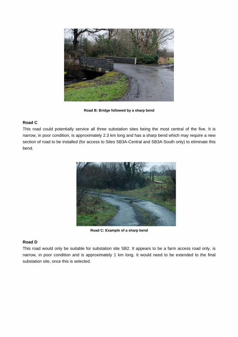
Road B: Bridge followed by a sharp bend
Road C This road could potentially service all three substation sites being the most central of the five. It is narrow, in poor condition, is approximately 2.3 km long and has a sharp bend which may require a new section of road to be installed (for access to Sites SB3A-Central and SB3A-South only) to eliminate this bend.
Road C: Example of a sharp bend
Road D This road would only be suitable for substation site SB2. It appears to be a farm access road only, is narrow, in poor condition and is approximately 1 km long. It would need to be extended to the final substation site, once this is selected.
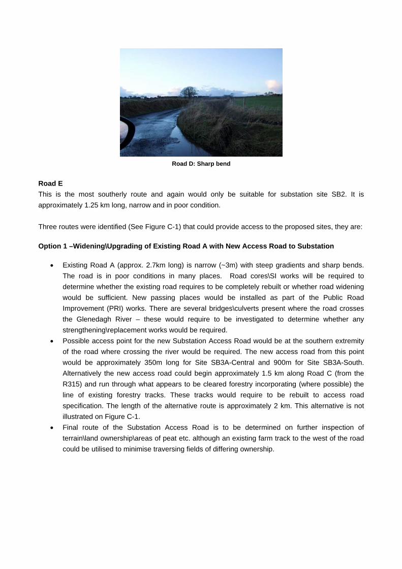
Road D: Sharp bend
Road E This is the most southerly route and again would only be suitable for substation site SB2. It is approximately 1.25 km long, narrow and in poor condition. Three routes were identified (See Figure C-1) that could provide access to the proposed sites, they are: Option 1 –Widening\Upgrading of Existing Road A with New Access Road to Substation
Existing Road A (approx. 2.7km long) is narrow (~3m) with steep gradients and sharp bends.
The road is in poor conditions in many places. Road cores\SI works will be required to determine whether the existing road requires to be completely rebuilt or whether road widening would be sufficient. New passing places would be installed as part of the Public Road Improvement (PRI) works. There are several bridges\culverts present where the road crosses the Glenedagh River – these would require to be investigated to determine whether any strengthening\replacement works would be required.
Possible access point for the new Substation Access Road would be at the southern extremity of the road where crossing the river would be required. The new access road from this point would be approximately 350m long for Site SB3A-Central and 900m for Site SB3A-South. Alternatively the new access road could begin approximately 1.5 km along Road C (from the R315) and run through what appears to be cleared forestry incorporating (where possible) the line of existing forestry tracks. These tracks would require to be rebuilt to access road specification. The length of the alternative route is approximately 2 km. This alternative is not illustrated on Figure C-1.
Final route of the Substation Access Road is to be determined on further inspection of terrain\land ownership\areas of peat etc. although an existing farm track to the west of the road could be utilised to minimise traversing fields of differing ownership.

Access roads

C-2 Proposed Access Routes to Sites SB3A-Central and SB3A-South Option 2 –Widening\Upgrading of Existing Road B with New Access Road to Substation
Existing Road B (approx. 2.3km long) appears to be in a similar poor condition as Road A and
road cores\SI works will be required to determine whether the existing road requires to be completely rebuilt or whether road widening would be sufficient. It is also too narrow for AIL transport, being ~3m wide. There are a series of sharp bends and an existing bridge across the Breaghwy River will require realignment to allow the transformer transporter access and strengthening. New Passing Places would be installed as part of the PRI works.
Possible access point for the new Substation Access Road would be from the western end of the road where it meets Road C. The new access road from this point would be approximately 1km long for Site SB3A-Central and 750m for Site SB3A-South. The access road would require bridging over the Breaghwy River.
Final route of the Substation Access Road to be determined on further inspection of terrain\land ownership\areas of peat etc. although an existing farm track to the west of the road could be utilised to minimise traversing fields of differing ownership.
Alternatively the new access road could begin prior to crossing the existing bridge thus avoiding possible realignment of the road and bridge strengthening works noted previously and could run partially along the line of an existing forestry track however this would increase the length of the access road considerably to approximately 1.6 km in length. (This alternative is not illustrated in Figure C-1)
Option 3 –Widening\Upgrading of Existing Road C with New Access Road to Substation Existing Road C (approx. 2.3km long) is also in poor condition and too narrow (~3m wide) and road cores\SI works will be required to determine whether the existing road requires to be completely rebuilt or whether road widening would be sufficient. New Passing Places would be installed as part of the PRI works. A 110m length of new road would be required to avoid negotiating a sharp bend as illustrated in the photograph above.
Possible access point for the new Substation Access Road would be from the western end of the road where it meets Road C. The new access road from this point would be approximately 1km long for Site SB3A-Central and 750m for Site SB3A-South. The access road would require bridging over the Breaghwy River.
Final route of the Substation Access Road to be determined on further inspection of terrain\land ownership\areas of peat etc. although an existing farm track to the west of the road could be utilised to minimise traversing fields of differing ownership.

C-3 Proposed Access Route to Site SB2 Three routes were identified (See Figure C-1) that could provide access to the SB2 substation site area; they are: Option 1 –Widening\Upgrading of Existing Road C with Upgrading of Existing Farm Access and New Access Road to Substation
Existing Road C which is the most northerly access route would be upgraded over approximately 1 km. Road cores\SI works will be required to determine whether the existing road would require to be completely rebuilt or whether road widening would be sufficient. New Passing Places would be installed as part of the PRI works.
From Road A an existing farm track (approx. 435m long) would also require upgrading to AIL\construction road standard including the incorporation of passing places.
Finally a new substation access road would be constructed to the substation site, the length of which would be determined by the final position of the substation. For estimating purposes this has been assumed to be 200m.
Option 2 –Widening\Upgrading of Existing Road D > Upgrading of Existing Farm Access > New Access Road to Substation
Existing Road D which is the central access route would be upgraded over approximately 0.4 km. The road is typically less than 3m wide. Road cores\SI works will be required to determine whether the existing road would require to be completely rebuilt or whether road widening would be sufficient. New Passing Places would be installed as part of the PRI works. There is a sharp bend along the route along which may require to be realigned as discussed and illustrated above.
From Road D an existing farm track (approx. 0.5 km long) would also require upgrading to AIL\construction road standard, including the incorporation of passing places.
Finally a new substation access road would be constructed to the substation site, the length of which would be determined by the final position of the substation. For estimating purposes this has been assumed to be 200m.
Option 3 –Widening\Upgrading of Existing Road E > Upgrading of Existing Farm Access > New Access Road to Substation
Existing Road E which is the most southerly access route would be upgraded over approximately 1.25 km where it is in poor condition in a number of places. Road cores\SI works will be required to determine whether the existing road would require to be completely rebuilt or whether road widening would be sufficient. New Passing Places would be installed as part of the PRI works. There is a sharp bend 2\3 of the way along which may require to be realigned
From Road E an existing farm track (approx. 0.75 km long) would also require upgrading to AIL\construction road standard including the incorporation of passing places.
Finally a new substation access road would be constructed to the substation, the length of which would be determined by the final position of the substation however an estimated length at this point would be around 0.3 km.

C-4 Estimates of Costs
Consideration has been given to anticipated costing for the upgrading and construction of the new roads set out in the various options above. This consideration is based on our experience of typical costs for the widening/upgrading of similar roads and the construction of this type of road in peat, making an allowance for potentially deep peat. The cost considerations include the following elements:
Replacement of existing road to AIL/Construction specification New road constructed in deep (up to 5m depth) peat Passing places Bridges Culverts and pipe crossing Maintenance during works and at completion of works
The following table summarises our consideration of costs of the different options.
Access to SB3A Sites Access to SB2 Sites
Option 1 Option 2 Option 3 Option 1 Option 2 Option 3
Replacement Road New road Passing places Bridges Culverts/Pipe Crossing Maintenance
Most Costly Least Costly