grid systems - ceilings from armstrong world · 48" 1-1/2" 1-1/2" yes ... for more...
TRANSCRIPT
DrywaLLGrid Systems
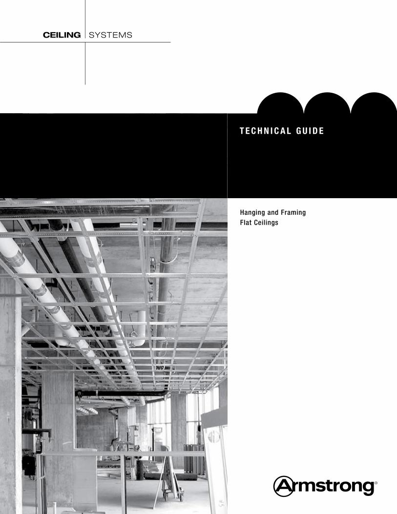
Hanging and FramingFlat Ceilings
T E C h N I C a L G u I D E
CEILING SYSTEMS

Work Smarter
Eliminate the labor-intensive cutting, tying, and spacing of track and channel framing. Our systems are engineered with route
locations and cross tees to maintain precise
module spacing. Main beams have 51 route locations
and cross tee lengths of 50", 26", and 14" to accommodate type
“F” fixtures without field modifications or accessories. Pre-notched main beams
simplify curved drywall installations.
Our Drywall Systems are manufactured to meet or exceed ASTM standards and code requirements, and are engineered to provide economical alternatives to stud and track construction.
DRYWALL Grid Systems
Meets:
• ASTM C635
• ASTM C645
• ASTM C754
• ASTM C840
• ICC Evaluation Service Report ESR-1289
• City of LA – RR 25348
• International Building Code, Continuous Membrane, One Level. Per Section 25.210, single level drywall ceilings are exempt from lateral force bracing requirements when walls are not over 50 feet apart. When walls are over 50 feet apart, the ceiling should be examined for bracing requirements
• IBC categories D, E, and F single layer drywall ceilings are exempt from lateral force bracing requirements, regardless of room size
• Miami-Dade County, Florida wind uplift – NOA No. 07-0119.02 – 03/17/2014
• Miami-Dade County, Florida impact testing – NOA No. 10-0126.04 – 03/17/2015
• Consult local codes for specific requirements
C o d e C o m p l i a n c e Yo u C a n Tr u s t• PeakForm® patented profile increases strength and stability for improved performance during installation
• SuperLock™2 main beam clip is engineered for a strong secure connection and fast accurate alignment confirmed with an audible click; easy to remove and relocate
• ScrewStop™ reverse hem prevents screw spin off on 1-1/2" wide face
• rotary-stitched – Greater torsional strength and stability
• 1-1/2" wide face main beams and cross tees – Easy installation of screw-applied gypsum wallboard
• G40, G90 hot dipped galvanized coating – Corrosion resistance
P e r f o r m a n c e
2
dry
wa
ll g
rid
sy
ste
ms

3
16-19 Suspended Drywall Grid System Details
20-30 Hanging and Framing 20 Wire Loading 20 9 Gauge Wire Breaking Strength and Technical Data 20 12 Gauge Wire Breaking Strength and Technical Data 20 Counter Splayed Wires 21 Yoke Wire Hung Ceilings 21 Single Yoke 21 Double Yoke 22 Trapeze Supported Loads 23 Double Hung Ceilings 23 Gusset Hung Ceilings 24 Triple Hung Ceilings 25 Wind Load 26-27 UL Fire Resistive Designs 27 Fire Rated Expansion Joint 28 Load Test Data 28 Membrane Load Values 29 Basic Products Used on Suspension Systems 29 Control Joints & Expansion Joints 30 Sound Isolation
31 Estimating Materials
Flat Drywall Grid Installation
Table of Contents 2 Code Compliance 2-3 Performance
4 Components 4 Main Beams 4 Cross Tees
5 Moldings 5 Wall Molding 6 G40 and G90 Corrosion Prevention 6 Transitions Wall Molding
7-10 Axiom® Trim 7 Transitions Trim 8 One-Piece Drywall Trim 9-10 Building Perimeter System
11-12 Route Locations
12-13 Accessories
14-15 Hanging and Framing 14 System Framing 14 Squaring Up the System 15 Type “F” Fixtures
• G90 hot dipped galvanized coating – Superior corrosion resistance for exterior applications
• heavy-duty load rating – Minimum 16 Lbs/LF on main beams
• Fire rated – Applicable to 25 UL Fire Resistant designs (D501, D502, G523, G524, G527, G528, G529, G553, J502, L502, L508, L513, L515, L525, L526, L529, L564, P501, P506, P507, P508, P509, P510, P513, P514, P516). Item XL7936G90 and XL8965 are not fire rated.
Wind uplift and impact testing construction available, including Miami Dade/Broward County, Florida
• Cross tee spacing: 24" O.C. for 5/8" drywall 16" O.C. for 1/2" drywall
P e r f o r m a n c e

4
DRYWALL Grid Systems
Components
For more information call 1 877 ARMSTRONG
co
mp
on
en
ts
1/4"
9/16"
1-11/16"
1-1/2"
Main Beams
Item Number
LengthFace
DimensionProfileHeight
DutyLoad
FireRated Routes
Load Test Data (Lbs/LF)
PerspectiveL/360
Simple SpanL/240
Simple Span
2' 3' 4' 2' 3' 4'
HD8906HD8906G90HD8906hrC
144" 1-1/2" 1-11/16" Heavy Duty Yes
51 routes – starting
2-1/4" from each end† 95.5 35.8 18.76 139.85 52.24 28.14
HD8906IIC 144" 1-1/2" 1-11/16" Heavy Duty Yes
51 routes – starting
2-1/4" from each end† 95.5 35.8 18.76 139.85 52.24 28.14
HD890610 120" 1-1/2" 1-11/16" Heavy Duty Yes
51 routes – starting
2-1/4" from each end† 95.5 35.8 18.76 139.85 52.24 28.14
† Type “F” fixture compatible
1/4"
9/16"
1-11/16"
1-1/2"
Cross Tees
Item Number
LengthFace
DimensionProfileHeight
FireRated Routes
Load Test Data (Lbs/LF)
PerspectiveL/360
Simple SpanL/240
Simple Span
72" 72"
XL8965XL8965hrC 72" 1-1/2" 1-1/2" Yes 6 routes – starting
24" from each end† 4.27 6.4
50" 50"
XL8947P XL8947PG90 50" 1-1/2" 1-1/2" Yes 8 routes – starting
10" from each end† 13.0 19.5
2' 3' 4' 2' 3' 4'
XL8945P XL8945PG90 XL8945hrC
48" 1-1/2" 1-1/2" Yes9 routes – center route and starting
10" from each end†15.0 22.5
XL8341 48" 15/16" 1-11/16" Yes 3 routes – starting 12" from each end 16.59 24.89
XL7341 48" 15/16" 1-11/16" Yes 3 routes – starting 12" from each end 16.59 24.89
XL7936G90 36" 1-1/2" 1-1/2" No none 33.33 49.96
XL8925XL8925G90 26" 1-1/2" 1-1/2" Yes 2 routes – 12"
from each end† 98.0 117.0
XL8926 XL8926G90 24" 1-1/2" 1-1/2" Yes
3 routes – center route and 10" from
each end†129.0 158.0
XL7918 14" 1-1/2" 1-1/2" Yes none† 71.5 107.0
NOTE: All items available in High Recycled Content (HRC) as special order † Type “F” fixture compatible
4
1/4"
9/16"
1-11/16"
1-1/2"
For more information call 1 877 ARMSTRONG 5
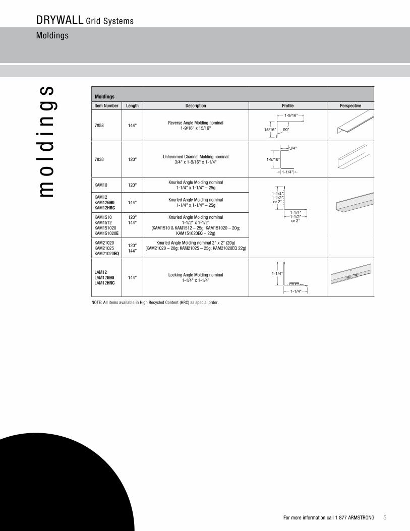
Moldings
Item Number Length Description Profile Perspective
7858 144"Reverse Angle Molding nominal
1-9/16" x 15/16"
7838 120"Unhemmed Channel Molding nominal
3/4" x 1-9/16" x 1-1/4"
KAM10 120"Knurled Angle Molding nominal
1-1/4" x 1-1/4" – 25g
KAM12 KAM12G90 KAM12hrC
144" Knurled Angle Molding nominal1-1/4" x 1-1/4" – 25g
KAM1510 KAM1512KAM151020 KAM151020E
120" 144"
Knurled Angle Molding nominal 1-1/2" x 1-1/2"
(KAM1510 & KAM1512 – 25g; KAM151020 – 20g; KAM151020EQ – 22g)
KAM21020 KAM21025 KAM21020EQ
120" 144"
Knurled Angle Molding nominal 2" x 2" (20g) (KAM21020 – 20g; KAM21025 – 25g; KAM21020EQ 22g)
LAM12LAM12G90LAM12hrC
144" Locking Angle Molding nominal 1-1/4" x 1-1/4"
NOTE: All items available in High Recycled Content (HRC) as special order.
DRYWALL Grid Systems
Moldings
mo
ldin
gs
11/2/987858PRO
90°
12/14/98
1/28/99
15/16"
1-9/16"
3/4"
1-9/16"
1-1/4"
1-1/4"
1-1/4"
1-1/4"1-1/2"or 2"
1-1/4"1-1/2"or 2"

6
DRYWALL Grid Systems
Moldings
Corrosion prevention is an essential factor in the economical utilization of galvanized sheet metal for ceiling suspension systems. Armstrong provides G40 for standard construction per ASTM C645. When conditions include exposure to extreme moisture and salt water, G90 is available per ASTM A653.
Drywall Transition Molding
Material: Commercial-quality cold rolled hot dipped galvanized steel
Item NumberLength/Item Description
Face Dimension Flange
Profile Height
7901 120" Shadow Reveal Molding 3/8" shadow reveal 9/16" 1-1/4"
7902 120" Shadow Reveal Molding 3/8" shadow reveal 15/16" 1-1/4"
7903 120" Inverted T Molding 1" inverted T – 1-1/2"
7904 7904PF*
120" Flush Transition Molding 15/16" horizontal 15/16" 1-1/4"
7905 7905PF*
120" Flush Transition Molding 9/16" horizontal 9/16" 1-1/4"
7906 120" “F” Molding 120" vertical transition – 1-7/16"
7907 120" Tegular Transition Molding 9/16" horizontal 9/16" 1-1/4"
7908 120" Tegular Transition Molding 15/16" horizontal 15/16" 1-1/4"
Corrosion Prevention
For more information call 1 877 ARMSTRONG
* 7904PF and 7905PF feature protective film on the acoustical wall angle flange for faster, easier finishing.

For more information call 1 877 ARMSTRONG 7
DRYWALL Grid Systems
Axiom® Trim
ax
iom
tra
ns
itio
ns
tri
m axiom – Transitions Trim
Material: Extruded aluminum, alloy 6063
Item NumberLength/Item Description
Dimensions
AXTRVESTR Straight Transition for Vector® 120 x 2-9/16 x 1-11/16"
AXTRTECUR Curved Transition for Tegular 120 x 2-9/16 x 1-11/16"
AXTR2STR 2" Straight Transition 120 x 2 x 1-1/2"
AXTR2CUR 2" Curved Transition 120 x 2 x 1-1/2"
AXTR4STR 4" Straight Transition 120 x 4 x 1-1/2"
AXTR4CUR 4" Curved Transition 120 x 4 x 1-1/2"
AXTR6STR 6" Straight Transition 120 x 6 x 1-1/2"
AXTR6CUR 6" Curved Transition 120 x 6 x 1-1/2"
AXTR8STR 8" Straight Transition 120 x 8 x 1-1/2"
AXBTSTR Drywall Bottom Trim 120 x 1-1/8 x 27/32"
aCCESSorIES
AX4SPLICEB Splice Plate –
AXTBC T-Bar Connector Clip –
Axiom – Transitions with Vector panel to drywall perimeter (AXTRVESTR)
Axiom – Transitions with Tegular panel to drywall perimeter (AXTRTESTR, AXTRTECUR)
AXTBC - TEE-BAR CONNECTIONCLIP
2", 4", 6", 8"
AXBTSTR
2", 4", 6", 8"
AXBTSTR
AXBTSTR
Acoustical-to-Drywall Drywall-to-Drywall
8
DRYWALL Grid Systems
Axiom® Trim
axi
om
dry
wa
ll t
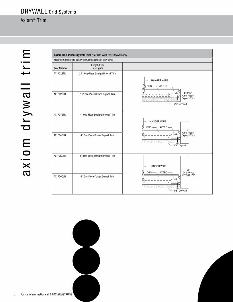
rim axiom one-Piece Drywall Trim *For use with 5/8" drywall only
Material: Commercial-quality extruded aluminum alloy 6063
Item NumberLength/Item Description
AX1PC2STR 2.5" One-Piece Straight Drywall Trim
AX1PC2CUR 2.5" One-Piece Curved Drywall Trim
AX1PC4STR 4" One-Piece Straight Drywall Trim
AX1PC4CUR 4" One-Piece Curved Drywall Trim
AX1PC6STR 6" One-Piece Straight Drywall Trim
AX1PC6CUR 6" One-Piece Curved Drywall Trim
5/8" Drywall
2-9/16"One-Piece Drywall Trim
DGS AXTBC
HANGER WIRE
5/8" Drywall
DGS AXTBC
HANGER WIRE
4"One-Piece Drywall Trim
DGS AXTBC
5/8" Drywall
6"One-Piece
Drywall Trim
HANGER WIRE
For more information call 1 877 ARMSTRONG
DRYWALL Grid Systems
Axiom® – Building Perimeter System
axi
om
bu
ild
ing
pe
rim
ete
r sy
ste
m
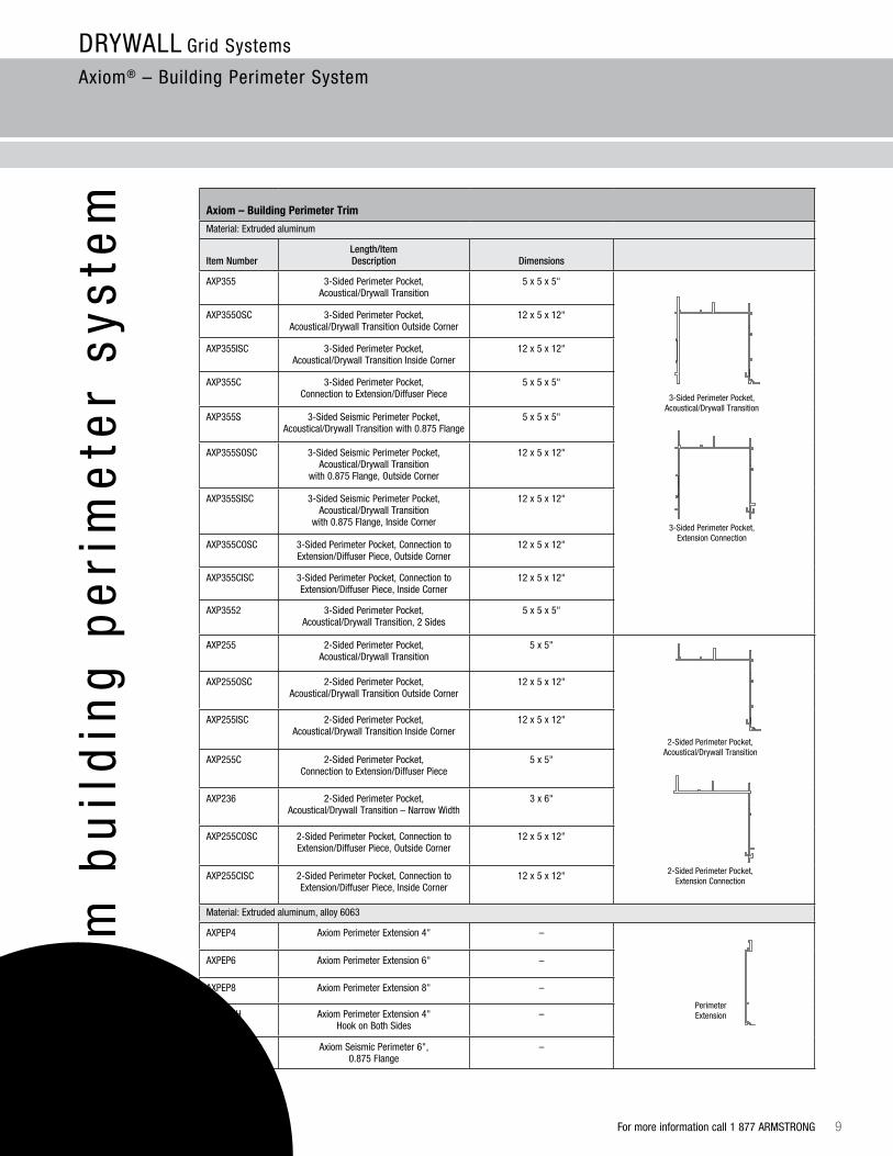
axiom – Building Perimeter Trim
Material: Extruded aluminum
Item NumberLength/Item Description
Dimensions
AXP355 3-Sided Perimeter Pocket, Acoustical/Drywall Transition
5 x 5 x 5"
AXP355OSC 3-Sided Perimeter Pocket, Acoustical/Drywall Transition Outside Corner
12 x 5 x 12"
AXP355ISC 3-Sided Perimeter Pocket, Acoustical/Drywall Transition Inside Corner
12 x 5 x 12"
AXP355C 3-Sided Perimeter Pocket, Connection to Extension/Diffuser Piece
5 x 5 x 5"
AXP355S 3-Sided Seismic Perimeter Pocket, Acoustical/Drywall Transition with 0.875 Flange
5 x 5 x 5"
AXP355SOSC 3-Sided Seismic Perimeter Pocket, Acoustical/Drywall Transition
with 0.875 Flange, Outside Corner
12 x 5 x 12"
AXP355SISC 3-Sided Seismic Perimeter Pocket, Acoustical/Drywall Transition
with 0.875 Flange, Inside Corner
12 x 5 x 12"
AXP355COSC 3-Sided Perimeter Pocket, Connection to Extension/Diffuser Piece, Outside Corner
12 x 5 x 12"
AXP355CISC 3-Sided Perimeter Pocket, Connection to Extension/Diffuser Piece, Inside Corner
12 x 5 x 12"
AXP3552 3-Sided Perimeter Pocket, Acoustical/Drywall Transition, 2 Sides
5 x 5 x 5"
AXP255 2-Sided Perimeter Pocket, Acoustical/Drywall Transition
5 x 5"
AXP255OSC 2-Sided Perimeter Pocket, Acoustical/Drywall Transition Outside Corner
12 x 5 x 12"
AXP255ISC 2-Sided Perimeter Pocket, Acoustical/Drywall Transition Inside Corner
12 x 5 x 12"
AXP255C 2-Sided Perimeter Pocket, Connection to Extension/Diffuser Piece
5 x 5"
AXP236 2-Sided Perimeter Pocket, Acoustical/Drywall Transition – Narrow Width
3 x 6"
AXP255COSC 2-Sided Perimeter Pocket, Connection to Extension/Diffuser Piece, Outside Corner
12 x 5 x 12"
AXP255CISC 2-Sided Perimeter Pocket, Connection to Extension/Diffuser Piece, Inside Corner
12 x 5 x 12"
Material: Extruded aluminum, alloy 6063
AXPEP4 Axiom Perimeter Extension 4" –
AXPEP6 Axiom Perimeter Extension 6" –
AXPEP8 Axiom Perimeter Extension 8" –
AXPEP4H Axiom Perimeter Extension 4" Hook on Both Sides
–
AXPEPS6 Axiom Seismic Perimeter 6", 0.875 Flange
–
3-Sided Perimeter Pocket, Acoustical/Drywall Transition
3-Sided Perimeter Pocket, Extension Connection
2-Sided Perimeter Pocket, Acoustical/Drywall Transition
2-Sided Perimeter Pocket, Extension Connection
Perimeter Extension
For more information call 1 877 ARMSTRONG 9

10
DRYWALL Grid Systems
Axiom® – Building Perimeter System
axiom – Building Perimeter System (continued)
Material: Extruded aluminum, alloy 6063
Item NumberLength/Item Description
Dimensions
AXPDFP4DT Axiom Perimeter Diffuser Face Plate 4" Drywall Transition (Unslotted)
–
AXPDFP4DTSLA Axiom Perimeter Diffuser Face Plate 4" Drywall Transition (Slotted 3/4" x 23" / 2-Slot Pattern)
–
AXPDFP4DTSLB Axiom Perimeter Diffuser Face Plate 4" Drywall Transition (Slotted 2-3/4" x 23" / 1-Slot Pattern)
–
AXPDFP7DT Axiom Perimeter Diffuser Face Plate 7" Drywall Transition (Unslotted)
–
AXPDFP7DTSLA Axiom Perimeter Diffuser Face Plate 7" Drywall Transition (Slotted 3/4" x 23" / 2-Slot Pattern)
–
AXPDFP7DTSLB Axiom Perimeter Diffuser Face Plate 7" Drywall Transition (Slotted 2-3/4" x 23" / 1-Slot Pattern)
–
AXPDFP4DT Axiom Perimeter Diffuser Face Plate Drywall Transition 4" (Unslotted)
–
AXPCC2 2" Axiom Building Perimeter Closure Clip –
AXPCC3 3" Axiom Building Perimeter Closure Clip –
AXPDFPS7 Axiom Seismic Perimeter Diffuser Face Plate 7" with 0.875 Flange (Unslotted) (120" x 7-13/16")
–
AXPDFPS7SLA Axiom Seismic Perimeter Diffuser Face Plate 7" with 0.875 Flange (Slotted 3/4" x 23" / 2-Slot Pattern) (120" x 7-13/16")
–
AXPDFPS7SLB Axiom Seismic Perimeter Diffuser Face Plate 7" with 0.875 Flange (Slotted 2-3/4" x 23" / 1-Slot Pattern)
(120" x 7-13/16")
–
AXCPCI Axiom Building Perimeter End Plate –
4” Diffuser Face Plate
7” Diffuser Face Plate
For more information call 1 877 ARMSTRONG
Slotted Face Plate (Item AXPDFP7SLA)
HVAC Boot
Splice Plate(Item AX4SPLICE)
3-Sided Perimeter Pocket,Connection to Extension
(Item AXP355C)
T-BarConnection Clip
(Item AXTBC)
Armstrong Drywall Grid Main Beam
2" Closure Clip(Item AXPCC2)
Window
Optional Stud
Hanger WireInstallationto Structure
Foam Gasket(Item AXPFG)
Drywall Taping Flange(Item AXDWT)
5/8" Thick Drywall
Armstrong Drywall Grid Cross Tee
Interlocking Spline(Item AXPSPLINE)
For more information, visit our website at armstrong.com/axiom or download BPCS-3911 Axiom Building Perimeter System Brochure or BPCS-3923 Axiom Building Perimeter Data Page.
axi
om
bu
ild
ing
pe
rim
ete
r sy
ste
m
Three-sided Perimeter Pocket with Face Plate
For more information call 1 877 ARMSTRONG 11
DRYWALL Grid Systems
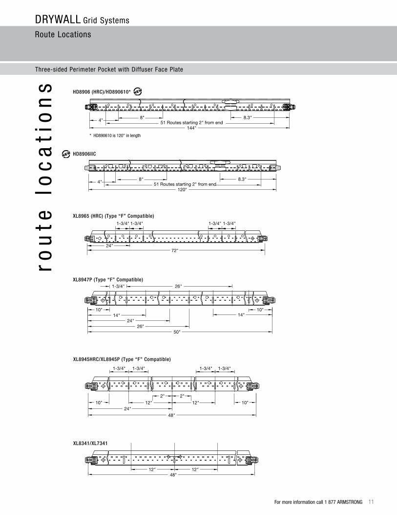
Route Locations
Note: All dimensions are nominal
26"1-3/4"
1-3/4" 1-3/4" 1-3/4"
72"24"
1-3/4"
10" 10"14" 14"
24"26"
50"
1-3/4" 1-3/4" 1-3/4" 1-3/4"
2" 2"
12"12" 10" 10"24"
48"
12"1-3/4"
26"
1-3/4" 1-3/4"
24"12"
14"
48"
36"
12"12"
4" 8" 8.3"51 Routes starting 2" from end
144"XL8965 (HRC) (Type “F” Compatible)
Note: All dimensions are nominal
26"1-3/4"
1-3/4" 1-3/4" 1-3/4"
72"24"
1-3/4"
10" 10"14" 14"
24"26"
50"
1-3/4" 1-3/4" 1-3/4" 1-3/4"
2" 2"
12"12" 10" 10"24"
48"
12"1-3/4"
26"
1-3/4" 1-3/4"
24"12"
14"
48"
36"
12"12"
4" 8" 8.3"51 Routes starting 2" from end
144"
XL8947P (Type “F” Compatible)
HD8906 (HRC)/HD890610*
Note: All dimensions are nominal
26"1-3/4"
1-3/4" 1-3/4" 1-3/4"
72"24"
1-3/4"
10" 10"14" 14"
24"26"
50"
1-3/4" 1-3/4" 1-3/4" 1-3/4"
2" 2"
12"12" 10" 10"24"
48"
12"1-3/4"
26"
1-3/4" 1-3/4"
24"12"
14"
48"
36"
12"12"
4" 8" 8.3"51 Routes starting 2" from end
144"
HD8906IIC
Note: All dimensions are nominal
26"1-3/4"
1-3/4" 1-3/4" 1-3/4"
72"24"
1-3/4"
10" 10"14" 14"
24"26"
50"
1-3/4" 1-3/4" 1-3/4" 1-3/4"
2" 2"
12"12" 10" 10"24"
48"
12"1-3/4"
26"
1-3/4" 1-3/4"
24"12"
14"
48"
36"
12"12"
4" 8" 8.3"51 Routes starting 2" from end
144"120"
4" 8" 8.3"51 Routes starting 2" from end
120"
Three-sided Perimeter Pocket with Diffuser Face Plate
rou
te l
oc
ati
on
s
XL8341/XL7341
Note: All dimensions are nominal
26"1-3/4"
1-3/4" 1-3/4" 1-3/4"
72"24"
1-3/4"
10" 10"14" 14"
24"26"
50"
1-3/4" 1-3/4" 1-3/4" 1-3/4"
2" 2"
12"12" 10" 10"24"
48"
12"1-3/4"
26"
1-3/4" 1-3/4"
24"12"
14"
48"
36"
12"12"
4" 8" 8.3"51 Routes starting 2" from end
144"
XL8945HRC/XL8945P (Type “F” Compatible)
Note: All dimensions are nominal
26"1-3/4"
1-3/4" 1-3/4" 1-3/4"
72"24"
1-3/4"
10" 10"14" 14"
24"26"
50"
1-3/4" 1-3/4" 1-3/4" 1-3/4"
2" 2"
12"12" 10" 10"24"
48"
12"1-3/4"
26"
1-3/4" 1-3/4"
24"12"
14"
48"
36"
12"12"
4" 8" 8.3"51 Routes starting 2" from end
144"
* HD890610 is 120" in length
12
ac
ce
ss
ori
es
30˚ 45˚
90˚60˚
DRYWALL Grid Systems
Route Locations & Accessories
Note: All dimensions are nominal
26"1-3/4"
1-3/4" 1-3/4" 1-3/4"
72"24"
1-3/4"
10" 10"14" 14"
24"26"
50"
1-3/4" 1-3/4" 1-3/4" 1-3/4"
2" 2"
12"12" 10" 10"24"
48"
12"1-3/4"
26"
1-3/4" 1-3/4"
24"12"
14"
48"
36"
12"12"
4" 8" 8.3"51 Routes starting 2" from end
144"
XL8925
Note: All dimensions are nominal
26"1-3/4"
1-3/4" 1-3/4" 1-3/4"
72"24"
1-3/4"
10" 10"14" 14"
24"26"
50"
1-3/4" 1-3/4" 1-3/4" 1-3/4"
2" 2"
12"12" 10" 10"24"
48"
12"1-3/4"
26"
1-3/4" 1-3/4"
24"12"
14"
48"
36"
12"12"
4" 8" 8.3"51 Routes starting 2" from end
144"
XL8926
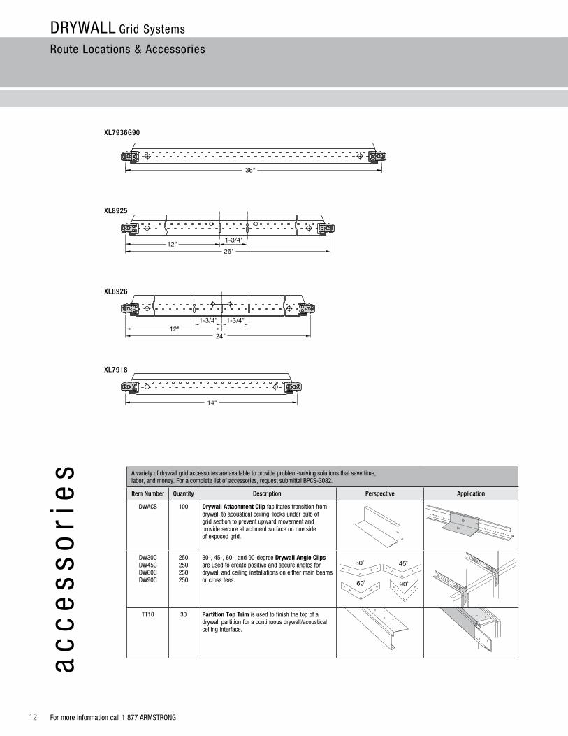
XL7936G90
Note: All dimensions are nominal
26"1-3/4"
1-3/4" 1-3/4" 1-3/4"
72"24"
1-3/4"
10" 10"14" 14"
24"26"
50"
1-3/4" 1-3/4" 1-3/4" 1-3/4"
2" 2"
12"12" 10" 10"24"
48"
12"1-3/4"
26"
1-3/4" 1-3/4"
24"12"
14"
48"
36"
12"12"
4" 8" 8.3"51 Routes starting 2" from end
144"
XL7918
Note: All dimensions are nominal
26"1-3/4"
1-3/4" 1-3/4" 1-3/4"
72"24"
1-3/4"
10" 10"14" 14"
24"26"
50"
1-3/4" 1-3/4" 1-3/4" 1-3/4"
2" 2"
12"12" 10" 10"24"
48"
12"1-3/4"
26"
1-3/4" 1-3/4"
24"12"
14"
48"
36"
12"12"
4" 8" 8.3"51 Routes starting 2" from end
144"
A variety of drywall grid accessories are available to provide problem-solving solutions that save time, labor, and money. For a complete list of accessories, request submittal BPCS-3082.
Item Number Quantity Description Perspective Application
DWACS 100 Drywall attachment Clip facilitates transition from drywall to acoustical ceiling; locks under bulb of grid section to prevent upward movement and provide secure attachment surface on one side of exposed grid.
DW30CDW45CDW60CDW90C
250250250250
30-, 45-, 60-, and 90-degree Drywall angle Clips are used to create positive and secure angles for drywall and ceiling installations on either main beams or cross tees.
TT10 30 Partition Top Trim is used to finish the top of a drywall partition for a continuous drywall/acoustical ceiling interface.
DWACDWAC
For more information call 1 877 ARMSTRONG

For more information call 1 877 ARMSTRONG 13
MBAC
accessories (continued)
Item Number Quantity Description Perspective Application
DW58LT 125 Dw58LT – Transition Clip for 5/8" Drywall with Locking Tabs; facilitates transition from drywall to acoustical ceiling; one-sided hold down clip; eliminates need for drywall bead. Locking tabs provide secure location for DGS tees.
DW50LT 125 Dw50LT – Transition Clip for 1/2" Drywall with Locking Tabs; facilitates transition from drywall to acoustical ceiling; one-sided hold down clip; eliminates the need for a drywall bead. Locking tabs provide secure location for DGS tees.
IIC 36 Impact Isolation Clip for use with HD8906IIC drywall grid main beam. Provides up to 8 points of IIC improvement to ensure your project meets IBC requirements.
MBSC2 200 Main Beam Spacer Clip (2" in length) is used to space two parallel main beams 2" O.C. for air supply or return.
GSC9 GSC12GSC16
100100 100
adjustable Grid Spacer Clip is used to space two parallel main beams for light fixtures, air diffusers, etc.; allows for 1/4" adjustments with three different clips.
XTAC 100 Cross Tee adapter Clip – Used to attach field-cut cross tees to main beams.
DDC 250 Double Drywall Clip is used to hang suspension system below existing 1-1/2" grid face, transferring weight directly to hanger wire; may be used to preserve the fire rating of an existing ceiling and to support heavy accessories; allows for double layer of 5/8" gypsum board.
DLCC 250 Direct Load Ceiling Clip is used to hang suspension system below existing 15/16" grid face, transferring weight directly to hanger wire; may be used to preserve the fire rating of an existing ceiling and to support heavy accessories.
DWC 250 Drywall Clip allows for a “second” ceiling to be installed below a drywall ceiling; attach through installed drywall to supporting structure.
MBAC 70 Main Beam adapter Clip attaches to web of suspension system section; provides larger surface for screw attachments; used as a hold down clip for thin material (metal or plastic lay-in panels); fastens drywall track to underside of exposed suspension system with lay-in panels, leaving suspension system face free of screw holes.
DRYWALL Grid Systems
Accessories
ac
ce
ss
ori
es
MBAC

14
DRYWALL Grid Systems
Hanging and Framing
System Framing
sy
ste
m f
ram
ing The grid system is comprised of main beams and cross tees
that are suspended by hanger wires to the structural deck. Sections of main beams lock together end-to-end while cross tees span between the main beams. The ends of the main beams and cross tees rest on the wall channel or angle molding that run around the perimeter of the space.
Squaring Up the System
Once you’ve hung your first two main beams and border cross tees, install two full cross tees between the main beams and in line with the first two border cross tees. To square up the system, simply measure across the diagonals of the opening. The measurements will be the same if the grid is square. If the grid is not square, shorten one of the main beams until the diagonals are equal.
KAM – Knurled Angle Molding
107 lbs. Pull Out and 372 lbs. Shear with 25 gauge Pan Head Streaker
Main Beam
Cross Tee
Gypsum Wall Board
A
B
Dimension “A” = Dimension “B”
For more information call 1 877 ARMSTRONG

For more information call 1 877 ARMSTRONG 15
XL8947P
XL8947P
Main Beams
48" OCMain Beams
72" OC
24"48"
50"
HD8906
XL8925
72"24"
26"
50"
XL8965
HD8906
XL8947P
XL8947P
XL8965XL8925
XL8925
50"
DRYWALL Grid Systems
Hanging and Framing
Type “F” Fixtures
Type “F” fixtures, access panels, and air diffusers require a full 12", 24", or 48" opening dimension. The Armstrong Drywall Grid System main beams and cross tees have additional routes in the web to accommodate this larger opening for type “F” fixtures. Using our 14", 26", 50", and 72" cross tees, type “F” fixtures fit perfectly without field cutting or special accessories.
When installing type “F” fixtures parallel to the main beams, use a 72" and 48" cross tee for easy placement of fixtures without field modifications.
When installing fixtures perpendicular to the main beams, use our 72" cross tees for virtually limitless fixture placement.
Main Beams
16
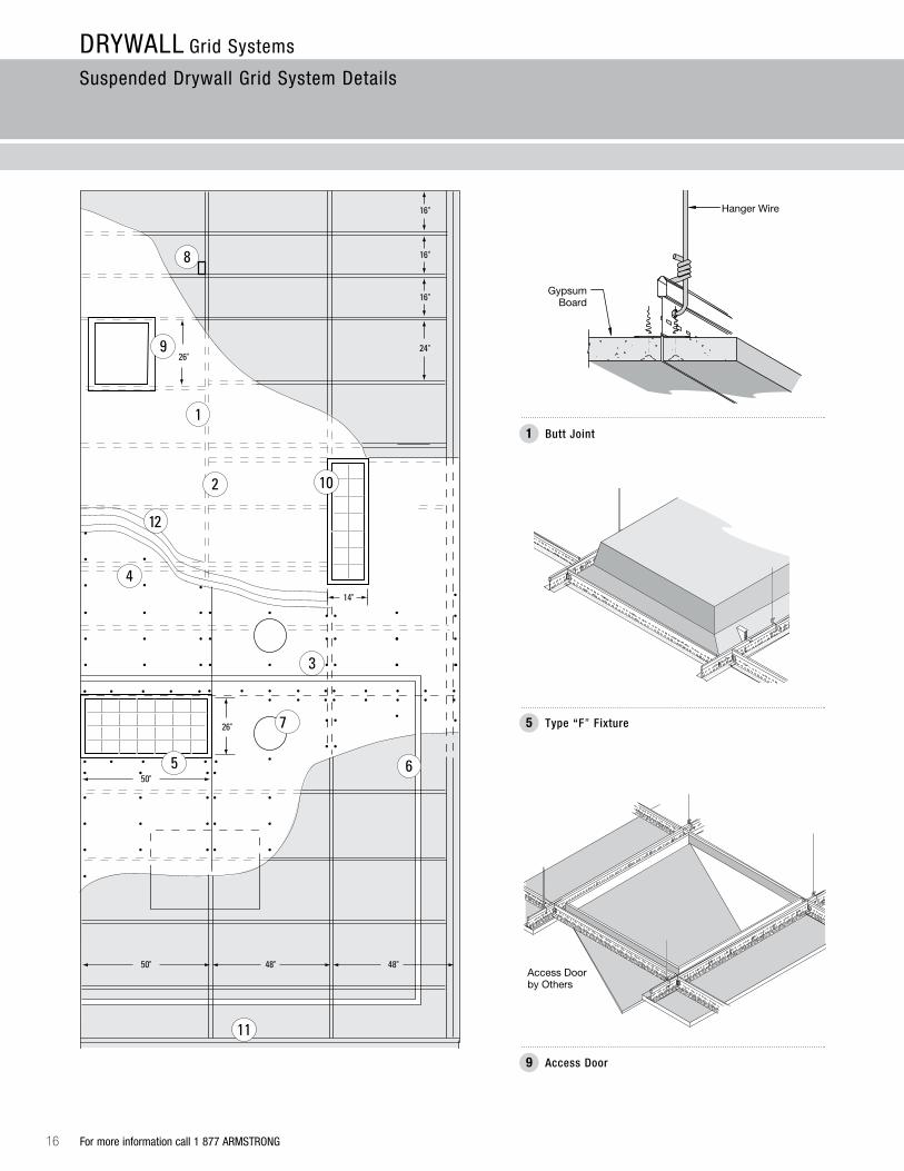
Hanger Wire
Gypsum Board
Access Doorby Others
DRYWALL Grid Systems
Suspended Drywall Grid System Details
For more information call 1 877 ARMSTRONG
Butt Joint1
Type “F” Fixture5
Access Door9
For more information call 1 877 ARMSTRONG 17
Main Beam
Cross Tee
Hanger Wire
Cross Tee
Wood TrimScrew
Hanger Wire
Armstrong Drywall Cross Tee
Expansion Joint*
Edge Bead
Armstrong Drywall
Main Beam
Drywall Screws
Hanger Wire
Angle Molding
Channel Molding
Steel Stud
Steel Stud
Hanger Wire
Twist to LockEnd of Clip in
Route
Main Beam
MainBeam
XTAC
MBSC2
Control Joint*
(MBSC2)Main Beam Spacer Clip
DRYWALL Grid Systems
Suspended Drywall Grid System Details
Expansion Joint*2 Wood Trim3 Control Joint 4
Air Bar6 High Hat Fixture7 Vertical Brace8
Securing a Single Cross Tee10 Channel and Angle Molding11 Angle Clip12
DW30C
DW45C
DW60C
DW90C
DW30C
DW45C
DW60C
DW90C
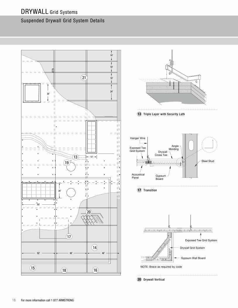
18
Exposed Tee Grid System
Drywall Grid System
Gypsum Wall Board
NOTE: Brace as required by code
Gypsum Board
Hanger Wire
DrywallCross Tee
Angle Molding
Steel Stud
AcousticalPanel
Exposed TeeGrid System
DRYWALL Grid Systems
Suspended Drywall Grid System Details
For more information call 1 877 ARMSTRONG
Triple Layer with Security Lath13
Transition17
Drywall Vertical20
For more information call 1 877 ARMSTRONG 19
Hanger Wire
Hanger Wire
Main Beam
Gypsum Board
Surface Mount Light Fixture (Screwed to Main Beam)Additional Wires May Be
Required to Support Load
Hanger Wire
Plywood orGypsum Board
Gypsum Board
Sound Isolator by Others
DLCC DDC
Drywall GridSystem
Axiom – Classic
AXTBC
5/8" Gypsum Wall Board
Axiom DrywallBottom Trim
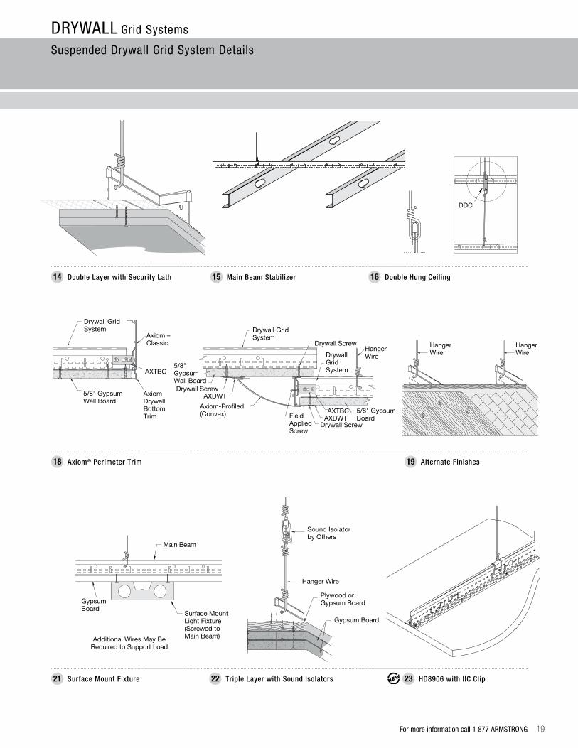
DRYWALL Grid Systems
Suspended Drywall Grid System Details
Double Layer with Security Lath14 Main Beam Stabilizer15 Double Hung Ceiling16
Axiom® Perimeter Trim18 Alternate Finishes19
HD8906 with IIC Clip23Surface Mount Fixture21 Triple Layer with Sound Isolators22
Drywall GridSystem
5/8" Gypsum Wall BoardDrywall Screw
AXDWT
Axiom-Profiled(Convex)
Drywall ScrewHanger Wire
AXDWT5/8" Gypsum BoardField
AppliedScrew
Drywall GridSystem
AXTBC
Drywall Screw

20
15º30º
45º
NOTE: If counter splayed wires are at unequal angles, refer to a local engineer or code official for approval.
DRYWALL Grid Systems
Hanging and Framing
Wire Loading
wir
e l
oa
din
g
For more information call 1 877 ARMSTRONG
Counter Splayed Wires
Objects in the plenum may obstruct placement of vertical hanger wires and require splayed wires to support the load. When this occurs, a second counter splayed wire must be added. Install counter splayed wires at an angle equal and opposite to the first wire, but not greater than 45° from vertical. The load capacity of the main beam remains unchanged (refer to ASTM C636).
9 Gauge wire Breaking Strength and Technical Data
12 Gauge wire Breaking Strength and Technical Data
9 Gauge Wire
Diameter .148"Galvanized Steel
645 lbs.Maximum SafeWire Load
3 Turns in 3"Per ASTM C636
450 lbs. Pullout –Hanger Wire Hole
12 Gauge Wire
Diameter .105"Galvanized Steel
275 lbs.Maximum SafeWire Load
3 Turns in 3"Per ASTM C636
500 lbs. Pullout –Hanger Wire Hole

For more information call 1 877 ARMSTRONG 21
8'
4'
45˚
4'
NOTE: Maintain wire spacing at a maximum 4' on center.
5/8" Type USS flat washer or equivalent
5/8" Type USS flat washer or equivalent
12'
6'
4'
45˚ Max.
Gypsum Wall Board
5/8" Type USS Flat Washer
or Equivalent
NOTE: Maintain wire spacing at a maximum 4' on center.
yo
ke
wir
eDRYWALL Grid Systems
Hanging and Framing
Yoke Wire Hung Ceilings
Single Yoke
Double Yoke
Another method to install hanger wires around an object in the plenum is to utilize a single or double yoke wire technique.
rule: To form the 45-degree angle, the vertical location of the tension ring is always half the distance of the span at the structure.
22 For more information call 1 877 ARMSTRONG
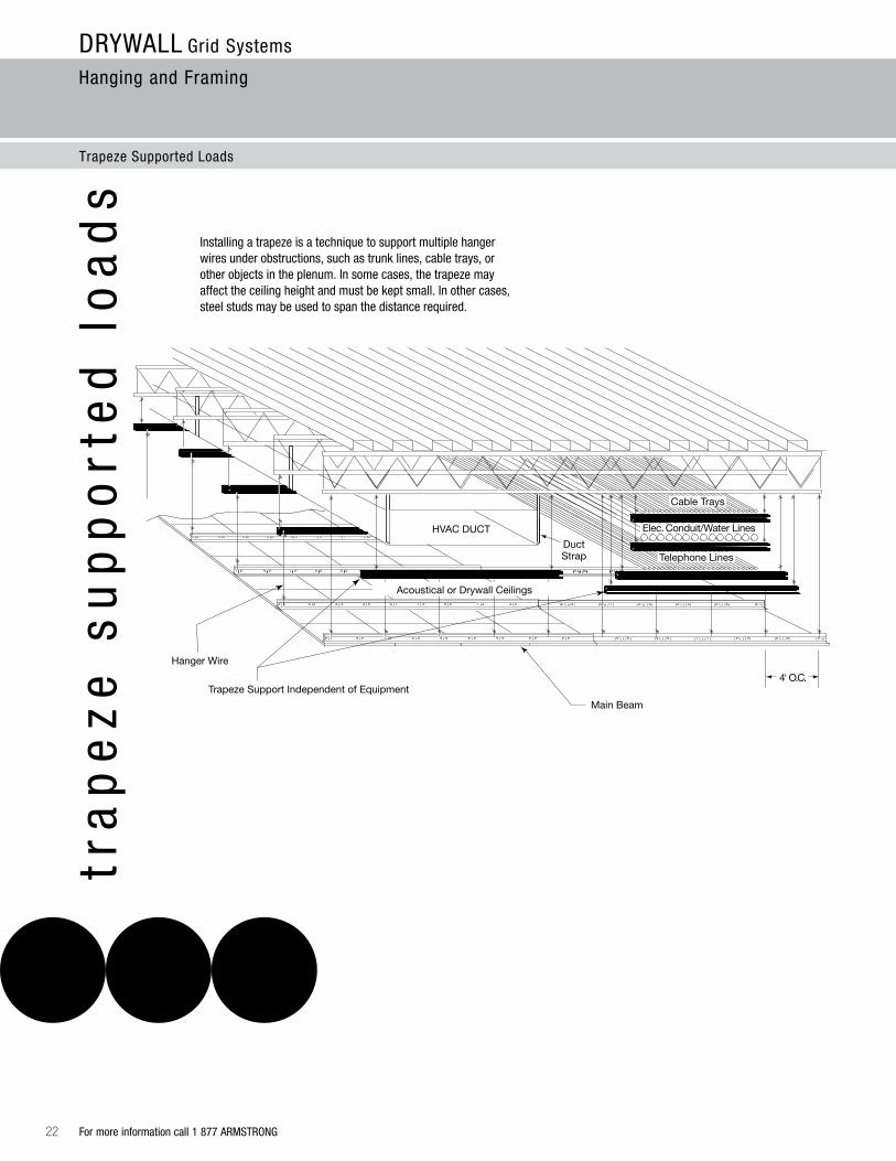
HVAC DUCT
4' O.C.
Main Beam
Cable Trays
Telephone Lines
Trapeze Support Independent of Equipment
Hanger Wire
DuctStrap
Acoustical or Drywall Ceilings
Elec. Conduit/Water Lines
DRYWALL Grid Systems
Hanging and Framing
Trapeze Supported Loads
tra
pe
ze
su
pp
ort
ed
lo
ad
s
Installing a trapeze is a technique to support multiple hanger wires under obstructions, such as trunk lines, cable trays, or other objects in the plenum. In some cases, the trapeze may affect the ceiling height and must be kept small. In other cases, steel studs may be used to span the distance required.
For more information call 1 877 ARMSTRONG 23
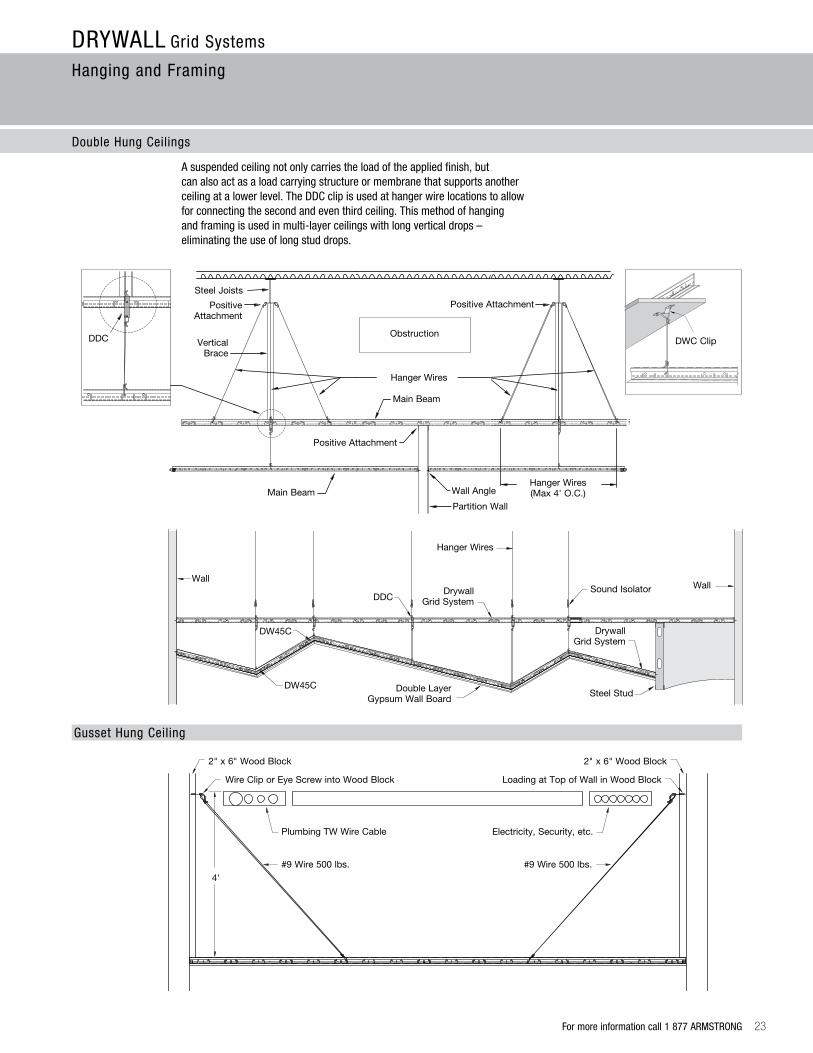
2" x 6" Wood Block
Wire Clip or Eye Screw into Wood Block
Plumbing TW Wire Cable
#9 Wire 500 lbs.4'
2" x 6" Wood Block
Loading at Top of Wall in Wood Block
Electricity, Security, etc.
#9 Wire 500 lbs.
Hanger Wires
Wall
DDCDrywall
Grid SystemSound Isolator Wall
DW45C
DW45C Double LayerGypsum Wall Board
Steel Stud
DrywallGrid System
DLCC DLCC DLCC DDC
Steel Joists
PositiveAttachment
Positive Attachment
Vertical Brace
Hanger Wires
Main Beam
Wall Angle
Partition Wall
Hanger Wires (Max 4' O.C.)
Positive Attachment
Main Beam
ObstructionDWC Clip
DRYWALL Grid Systems
Hanging and Framing
Double Hung Ceilings
Gusset Hung Ceiling
A suspended ceiling not only carries the load of the applied finish, but can also act as a load carrying structure or membrane that supports another ceiling at a lower level. The DDC clip is used at hanger wire locations to allow for connecting the second and even third ceiling. This method of hanging and framing is used in multi-layer ceilings with long vertical drops – eliminating the use of long stud drops.

24
Roof Deck
Bar Joist
Drywall Main Beam
DDC
Gypsum Board
Steel Stud
Drywall Main Beam
Channel Molding
DW90C
Channel Molding
Gypsum Board
DuctPipe Chase
Insulation
1st
2nd
3rd
Drywall Grid System
Drywall Grid SystemDW45C
DDC Clip
Drywall Grid System
DRYWALL Grid Systems
Hanging and Framing
Triple Hung Ceilings
For more information call 1 877 ARMSTRONG
ce
ilin
g t
ype

For more information call 1 877 ARMSTRONG 25
DRYWALL Grid Systems
Hanging and Framing
Exterior wind Load Ceiling Design For North america
PlenumHeight(ft.-in.)
Design Wind
Velocity (MPH)
Design Wind
Pressure (PSF)
Compression Post Size
(Inch)
Compression Post
Gauge (Ga. No.)
Sheathing Membrane Substrate 5/8" Drywall Sheet Densglass Gold G-P
Compression Post
Spacing (ft.-in.)
Main Beam
Spacing (Inch)
Cross Tee
Spacing(Inch)
Hanger Wire
Spacing(ft.-in.)
Cross Tee
Length(Feet)
CompressionPost Load
Design Load(Lbs.)
0
6'***
15 5.07 2-1/2" CWN 20 5/8" G.P. Densglass & 1/4"-3/8" EIFS 4' – 2" 48" 16" 4' 4' 18
30 2.03 2-1/2" CWN 20 5/8" G.P. Densglass & 1/4"-3/8" EIFS 4' – 2" 48" 16" 4' 4' 49
45 4.56 2-1/2" CWN 20 5/8" G.P. Densglass & 1/4"-3/8" EIFS 3' – 6" 48" 16" 4' 4' 96
60 8.1 2-1/2" CWN 20 5/8" G.P. Densglass & 1/4"-3/8" EIFS 3' – 6" 36" 16" 4' 3' 125
90 18.24 2-1/2" CWN 20 5/8" G.P. Densglass & 1/4"-3/8" EIFS 3' – 4" 24" 16" 3' 2' 178
120 32.43 2-1/2" CWN 20 5/8" G.P. Densglass & 1/4"-3/8" EIFS 2' – 8" 24" 16" 2' – 6" 2' 266
140 44.14 2-1/2" CWN 18 5/8" G.P. Densglass & 1/4"-3/8" EIFS 2' – 4" 24" 16" 2' – 6" 2' 331
172 75 2-1/2" CSJ 18 See NOA 12-0314.05 Design 2' 24" 16" 2' 2' 445
172 75 2-1/2" CSJ 18 See NOA 12-0314.04 Design 2' – 6" 36" 16" 2' – 6" 3' 565
6' 1"
10' 3"****
15 5.07 2-1/2" CSJ 18 5/8" G.P. Densglass & 1/4"-3/8" EIFS 4' – 2" 48" 16" 4' 4' 18
30 2.03 2-1/2" CSJ 18 5/8" G.P. Densglass & 1/4"-3/8" EIFS 3'-10" 48" 16" 4' 4' 49
45 4.56 2-1/2" CSJ 18 5/8" G.P. Densglass & 1/4"-3/8" EIFS 3' – 6" 48" 16" 4' 4' 96
60 8.1 2-1/2" CSJ 18 5/8" G.P. Densglass & 1/4"-3/8" EIFS 3' – 6" 36" 16" 4' 3' 125
90 18.24 2-1/2" CSJ 18 5/8" G.P. Densglass & 1/4"-3/8" EIFS 3' – 4" 36" 16" 3' 2' 178
120 32.43 2-1/2" CSJ 18 5/8" G.P. Densglass & 1/4"-3/8" EIFS 2' – 8" 24" 16" 2' – 6" 2' 266
140 44.14 2-1/2" CSJ 18 5/8" G.P. Densglass & 1/4"-3/8" EIFS 2' – 4" 24" 16" 2' – 6" 2' 331
172 75 2-1/2" CSJ 18 See NOA 12-0314.05 Design 2' 24" 16" 2' 2' 445
172 75 2-1/2" CSJ 18 See NOA 12-0314.04 Design 2' – 6" 36" 16" 2' – 6" 3' 565
10' 4"
15' 0"****
*15 5.07 2-1/2" CSJ 18 5/8" G.P. Densglass & 1/4"-3/8" EIFS 4' – 2" 48" 16" 4' 4' 18
*30 2.03 2-1/2" CSJ 18 5/8" G.P. Densglass & 1/4"-3/8" EIFS 3'-10" 48" 16" 4' 4' 49
*45 4.56 2-1/2" CSJ 18 5/8" G.P. Densglass & 1/4"-3/8" EIFS 3' – 6" 48" 16" 4' 4' 96
*60 8.1 2-1/2" CSJ 18 5/8" G.P. Densglass & 1/4"-3/8" EIFS 3' – 6" 36" 16" 4' 3' 125
*90 18.24 2-1/2" CSJ 18 5/8" G.P. Densglass & 1/4"-3/8" EIFS 3' – 4" 36" 16" 3' 2' 178
*120 32.43 2-1/2" CSJ 18 5/8" G.P. Densglass & 1/4"-3/8" EIFS 2' – 8" 24" 16" 2' – 6" 2' 266
*140 44.14 2-1/2" CSJ 18 5/8" G.P. Densglass & 1/4"-3/8" EIFS 2' – 4" 24" 16" 2' – 6" 2' 331
*172 75 2-1/2" CSJ 18 See NOA 12-0314.05 Design 2' 24" 16" 2' 2' 445
*172 75 2-1/2" CSJ 18 See NOA 12-0314.04 Design 2' – 6" 36" 16" 2' – 6" 3' 565
15' 1"
20' 0"****
**15 5.07 3-5/8" CSJ 18 5/8" G.P. Densglass & 1/4"-3/8" EIFS 4' – 2" 48" 16" 4' 4' 18
**30 2.03 3-5/8" CSJ 18 5/8" G.P. Densglass & 1/4"-3/8" EIFS 3' – 10" 48" 16" 4' 4' 49
**45 4.56 3-5/8" CSJ 18 5/8" G.P. Densglass & 1/4"-3/8" EIFS 3' – 6" 48" 16" 4' 4' 96
**60 8.1 3-5/8" CSJ 18 5/8" G.P. Densglass & 1/4"-3/8" EIFS 3' – 6" 36" 16" 4' 3' 125
**90 18.24 3-5/8" CSJ 18 5/8" G.P. Densglass & 1/4"-3/8" EIFS 3' – 4" 36" 16" 3' 2' 178
**120 32.43 3-5/8" CSJ 18 5/8" G.P. Densglass & 1/4"-3/8" EIFS 2' – 8" 24" 16" 2' – 6" 2' 266
**140 44.14 3-5/8" CSJ 18 5/8" G.P. Densglass & 1/4"-3/8" EIFS 2' – 4" 24" 16" 2' – 6" 2' 331
**172 75 3-5/8" CSJ 18 See NOA 12-0314.05 Design 2' 24" 16" 2' 2' 445
**172 75 3-5/8" CSJ 18 See NOA 12-0314.04 Design 2' – 6" 36" 16" 2' – 6" 3' 565
* 1-1/2" 16 gauge U-Channel Bridging required at mid span for 10’4” up to 15’0” ** 1-1/2" 16 gauge U-Channel Bridging required at one-third points for 15’1” up to 20’0” *** Compression Post and Ceiling System tested at the plenum design depth shown here for positive and negative wind speed pressure loads as listed **** Compression Post Assemblies at this plenum design depth calculated by Dietrich Design Group NOTE: For building heights over 20 feet, refer to ASCE 7-10 Chapter 6 Wind Loads
26
DRYWALL Grid Systems
Hanging and Framing
For more information call 1 877 ARMSTRONG
fire
re
sis
tiv
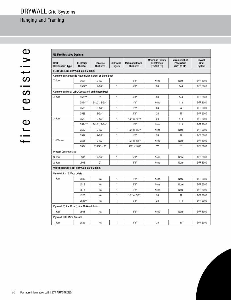
e uL Fire resistive Designs
Deck Construction Type
UL DesignNumber
Concrete Thickness
# Drywall Layers
Minimum Drywall Thickness
Maximum Fixture Penetration(Ft2/100 Ft2)
Maximum Duct Penetration (In2/100 Ft2)
Drywall Grid
System
FLoor/CEILING DrywaLL aSSEMBLIES
Concrete on Composite Flat Cellular, Fluted, or Blend Deck
2-Hour D501 2-1/2" 1 5/8" None None DFR 8000
D502** 2-1/2" 1 5/8" 24 144 DFR 8000
Concrete on Metal Lath, Corrugated, and Ribbed Deck
3-Hour G523** 3" 1 5/8" 24 144 DFR 8000
G524*** 3-1/2", 3-3/4" 1 1/2" None 113 DFR 8000
G529 3-1/4" 1 1/2" 24 57 DFR 8000
G529 2-3/4" 1 5/8" 24 57 DFR 8000
2-Hour G523 2-1/2" 1 1/2" or 5/8"* 24 144 DFR 8000
G524*** 3-1/2", 3-3/4" 1 1/2" None 113 DFR 8000
G527 2-1/2" 1 1/2" or 5/8"* None None DFR 8000
G529 2-1/2" 1 1/2" 24 57 DFR 8000
1-1/2-Hour G528 2-1/2" 1 1/2" or 5/8"* None None DFR 8000
G524 2-3/4" – 3" 1 1/2" or 5/8" *** *** DFR 8000
Precast Concrete Slab
3-Hour J502 2-3/4" 1 5/8" None None DFR 8000
2-Hour J502 2" 1 5/8" None None DFR 8000
wooD DECk/CEILING DrywaLL aSSEMBLIES
Plywood 2 x 10 Wood Joists
1-Hour L502 NA 1 1/2" None None DFR 8000
L513 NA 1 5/8" None None DFR 8000
L515 NA 1 1/2" None None DFR 8000
L525 NA 1 1/2" or 5/8"* 24 57 DFR 8000
L526** NA 1 5/8" 24 114 DFR 8000
Plywood (2) 2 x 10 or (1) 4 x 10 Wood Joists
1-Hour L508 NA 1 5/8" None None DFR 8000
Plywood with Wood Trusses
1-Hour L529 NA 1 5/8" 24 57 DFR 8000
27For more information call 1 877 ARMSTRONG
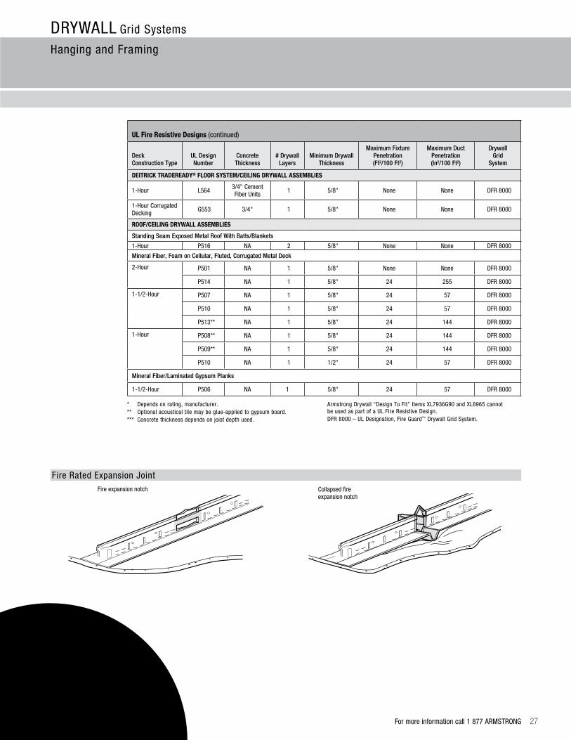
DRYWALL Grid Systems
Hanging and Framing
Fire expansion notch Collapsed fire expansion notch
* Depends on rating, manufacturer.** Optional acoustical tile may be glue-applied to gypsum board.*** Concrete thickness depends on joist depth used.
Armstrong Drywall “Design To Fit” Items XL7936G90 and XL8965 cannot be used as part of a UL Fire Resistive Design. DFR 8000 – UL Designation, Fire Guard™ Drywall Grid System.
Fire Rated Expansion Joint
uL Fire resistive Designs (continued)
Deck Construction Type
UL DesignNumber
Concrete Thickness
# Drywall Layers
Minimum Drywall Thickness
Maximum Fixture Penetration(Ft2/100 Ft2)
Maximum Duct Penetration (In2/100 Ft2)
Drywall Grid
System
DEITrICk TraDErEaDy® FLoor SySTEM/CEILING DrywaLL aSSEMBLIES
1-Hour L564 3/4" Cement Fiber Units 1 5/8" None None DFR 8000
1-Hour Corrugated Decking G553 3/4" 1 5/8" None None DFR 8000
rooF/CEILING DrywaLL aSSEMBLIES
Standing Seam Exposed Metal Roof With Batts/Blankets
1-Hour P516 NA 2 5/8" None None DFR 8000
Mineral Fiber, Foam on Cellular, Fluted, Corrugated Metal Deck
2-Hour P501 NA 1 5/8" None None DFR 8000
P514 NA 1 5/8" 24 255 DFR 8000
1-1/2-Hour P507 NA 1 5/8" 24 57 DFR 8000
P510 NA 1 5/8" 24 57 DFR 8000
P513** NA 1 5/8" 24 144 DFR 8000
1-Hour P508** NA 1 5/8" 24 144 DFR 8000
P509** NA 1 5/8" 24 144 DFR 8000
P510 NA 1 1/2" 24 57 DFR 8000
Mineral Fiber/Laminated Gypsum Planks
1-1/2-Hour P506 NA 1 5/8" 24 57 DFR 8000

For more information call 1 877 ARMSTRONG28
DRYWALL Grid Systems
Hanging and Framing
loa
d d
ata
Main Beam – Technical Load Test Data
Item Number
Flange Width (in.) Length (in.)
Web Height (in.)
Simple Span (Lbs/LF)
4' 3' 2'
L/240 L/360 L/240 L/360 L/240 L/360
HD8906 1-1/2" 144" 1-11/16" 28.14 18.66 57.3 43.19 143.0 95.5
HD8906IIC 1-1/2" 144" 1-11/16" 28.14 18.66 57.3 43.19 143.0 95.5
HD890610 1-1/2" 120" 1-11/16" 28.14 18.66 57.3 43.19 143.0 95.5
NOTE: Allowable loads tested per ASTM C635 for deflection limited to L/360 and complies with ASTM C645 for deflection limited to L/240. See standards for additional information.
Cross Tees – Technical Load Test Data
Item Number
Flange Width (in.) Length (in.)
Web Height (in.)
Simple Span (Lbs./LF)
72" 50" 4' 3' 2'
L/240 L/360 L/240 L/360 L/240 L/360 L/240 L/360 L/240 L/360
XL8965 1-1/2" 72" 1-1/2" 6.4 4.27
XL8947P 1-1/2" 50" 1-1/2" 19.5 13.0
XL8945P 1-1/2" 48" 1-1/2" 22.5 15.0
XL8341 15/16" 48" 1-1/2" 24.8 16.59
XL7341 15/16" 48" 1-11/16" 24.8 16.59
XL7936G90 1-1/2" 36" 1-1/2" 50.0 33.3
XL8925 1-1/2" 26" 1-1/2" 117.0 98.0
XL8926 1-1/2" 24" 1-1/2" 158.0 129.0
XL7918 1-1/2" 14" 1-1/2" 107.0 71.5
Membrane Load Values
Component Combinations
Maximum Load in lbs./ft.2 at Hanger Wire/Cross Tee Spacing
48 / 24 48 / 16 36 / 16
Main Cross Tee L/240 L/360 L/240 L/360 L/240 L/360
HD8906 – XL8965 3.20 4.66
HD8906 – XL8947P 6.78 4.52 6.78 4.52 13.41 8.95
HD8906 – XL8945P 7.03 4.69 7.03 4.69 14.93 9.95
HD8901 – XL8945P 6.18 4.12 6.18 4.12 11.61 7.74
HD8906 – XL7936G90 21.77 14.51
HD8901 – XL7936G90 21.77 14.51
HD8906 – XL8926 26.13 21.77

For more information call 1 877 ARMSTRONG 29
DRYWALL Grid Systems
Hanging and Framing
ba
sic
pro
du
cts
Control Joints Expansion Joints
Basic Products used on Suspension Systems
MaterialWeightLbs/SF
Maximum Main Beam
Spacing
Maximum Cross Tee Spacing
Maximum Wire
Spacing
Load on
Wire
OSB 1/4" 0.9 48" 8" – 16" 48" 14.4 Lbs.
3/8" 1.3 48" 16" 48" 20.8 Lbs.
1/2" 1.7 48" 16" 48" 27.2 Lbs.
5/8" 2.2 48" 24" 48" 35.2 Lbs.
3/4" 2.5 48" 24" 48" 40.0 Lbs.
Plywood 1/4" .075 48" 8" – 16" 48" 12.0 Lbs.
3/8" 1.1 48" 16" 48" 17.6 Lbs.
1/2" 1.5 48" 16" 48" 24.0 Lbs.
5/8" 1.8 48" 24" 48" 28.8 Lbs.
3/4" 2.2 48" 24" 48" 35.2 Lbs.
Gypsum Board 1/4" 1.2 48" 8" – 16" 48" 19.2 Lbs.
3/8" 1.4 48" 16" 48" 22.4 Lbs.
1/2" 2.0 48" 16" 48" 32.0 Lbs.
5/8" 2.4 48" 24" 48" 38.4 Lbs.
3/4" 4.2 48" 16" 48" 67.2 Lbs.
Cement Board 1/2"* 3.0 48" 24" 48" 48.0 Lbs.
Cement Siding 5/8"* 1.9 48" 16" 48" 30.4 Lbs.
Hard Board Siding 1/2" 2.0 48" 16" 48" 32.0 Lbs.
Water-Resistant Gypsum Board 5/8" 3.42 48" 16" or 24" 48" 57.7 Lbs.
Water-Resistant Gypsum Board 1/2" 2.8 48" 16" 48" 44.8 Lbs.
Expanded Steel Lath 3.4 48" 16" 48" 54.4 Lbs.
12 Gauge Sheet Steel 4.5 24" 16" 48" 72.0 Lbs.
NOTES: All framing on the exterior should be 16" O.C. or less. Some manufacturers make 1/2" gypsum board with special core to span 24" framing on interior ceiling installations (available on request). All steel product on exterior made from G90 galvanized finish. Data based on manufacturer’s published data.
* Use lower RPM (1,000-2,500) screw gun to install cement board screws with intermittent pressure.
Please refer to ASTM C840, Section 20.3.3 to 20.4 for Control Joint Requirements.
Ceiling expansion joints are installed to separate the metal suspension system when expansion joints occur in buildings or when metal changes direction. Expansion joints are required to separate a system in T-, H-, I-, and U-, or circle-shaped buildings to eliminate cracking from expansion.

For more information call 1 877 ARMSTRONG30
DRYWALL Grid Systems
Hanging and Framing
so
un
d c
on
tro
l
armstrong Standard Drywall Grid assembly – Field Tested Data
Item Number Armstrong Assembly Building Structure STC IIC
HD8906XL8945
12' Main Beam / 4' Cross Tee3-1/2" Batt Insulation
5/8" Gypsum
Bare Concrete Base 3" Concrete Slab
Fluted Steel Decking 8" Bar Joist, 24" o.c.
55
47
armstrong IIC Drywall Grid assembly – Field Tested Data
Item Number Armstrong Assembly Building Structure STC IIC
HD8906IICXL8945IIC Clip
12' Main Beam / 4' Cross Tee IIC Clip
3-1/2" Batt Insulation5/8" Gypsum
6” Thick Slab Concrete Base with Vinyl Sheet
Flooring
57 66
Satisfy IBC requirements with a rating of 50 or above for STC and IIC sound tests – without two layers of drywall using Armstrong Drywall Grid.
Sound Control
Traditional assembly – Field Tested Data
Traditional Assembly Building Structure STC IIC
1-1/2" Black Iron / 7/8" Channel3-1/2" Batt Insulation
5/8" Gypsum
Bare Concrete Base 3" Concrete Slab
Fluted Steel Decking 8" Bar Joist, 24" o.c.
55 48
The IBC uses two sound classes to measure sound isolation performance in building construction: Sound Transmission Class (STC) – sound transmitted through the air such as voices and music. Impact Insulation Class (IIC) – sound transmitted through the building structure such as foot traffic and objects dropped on the floor.
A rating of 50 or above for both STC and IIC sound tests will satisfy the IBC’s minimum requirements.
understanding Sound Control ratings
STC/IIC Ratings Description
55 Excellent
50 Loud speech barely audible
45 Some loud speech audible – not understood
30 Loud speech audible – well understood
25 Regular speech audible and understood through walls
HD8906IIC 12' Main Beam
XL8945 4' DGS Tee(Wires 4' O.C.)
3-1/2" Batt Insulation
Ceiling – One Layer 5/8" Gypsum
6" Thick Concrete: 3500psi
armstrong IIC Drywall Grid assembly
IIC Clip
Changes in STC/IIC Ratings Description
+ / - 1 Almost perceptible
+ / - 3 Just perceptible
+ / - 5 Clearly Perceptible
+ / - 10 Twice (or half) as loud
Vinyl Sheet Flooring

es
tim
ati
ng
Item Number Length Pcs/Ctn LF/Ctn Lbs./Ctn
Area of ceiling completed by one carton (SF)
8" O.C.
16" O.C.
24" O.C.
36" O.C.
48" O.C.
50" O.C.
72" O.C.
DrywaLL GrID MaIN BEaM
HD8906/HD8906G90/HD8906IIC 144" 12 144 53 288 432 576 600 864
HD8906F08/HD8906F16 144" 12 144 53 Varies with radius
HD890610 120" 12 120 49 288 432 576 600 864
DrywaLL GrID 1-1/2" FaCE CroSS TEES
XL8965 72" 36 216 78 144 288 432
XL8947P/XL8947PG90** 50" 36 150 56 100 200 300
XL8945P/XL8945PG90 48" 36 144 52 96 192 288
XL7936G90 36" 36 108 39 72 144 216
XL8925/XL8925G90** 26" 36 78 28
XL8926/XL8926G90 24" 36 72 26 48
XL7918** 14" 36 42 14
DrywaLL GrID 15/16" FaCE CroSS TEES
XL7341/XL8341 48" 60 240 71 320 480
** Dimensions are nominal.
Item Number Length Pcs/Ctn LF/Ctn Lbs/Ctn
rEVErSE MoLDINGS
7857 120" 30 360 51
7858 120" 20 240 67
DrywaLL uNhEMMED ChaNNEL MoLDING
7838 120" 20 200 36
DrywaLL aNGLE MoLDING
HD7801G90 120" 30 300 38
KAM-12 144" 20 240 39
KAM-10 120" 20 200 33
LAM-12 144" 20 240 39
Estimating Lineal Feet of Grid Based on Square Footage of Ceiling
On-center Spacing of Component
Percent of Square Footage
8" 108%
12" 100%
16" 76%
20" 60%
24" 50%
30" 40%
36" 33%
48" 25%
60" 20%
Example calculation based on 5,100 SF ceiling:
Main beam at 48" O.C. 5,100 SF x .25 = 1,275 LF 1,275 LF ÷ 144 LF/Ctn = 9 cartons needed
Cross tee at 16" O.C. 5,100 SF x .76 = 3,876 LF 3,876 LF ÷ 144 LF/Ctn = 27 cartons needed
Cross tee at 24" O.C. 5,100 SF x .50 = 2,550 LF 2,550 LF ÷ 144 LF/Ctn = 18 cartons needed
For more information call 1 877 ARMSTRONG 31
DRYWALL Grid Systems
Estimating Material
TechLineSM / 1 877 ARMSTRONG
1 877 276 7876
armstrong.com/drywallgrid
BPCS-3539-614
C E I L I N G S y s t e m s
1 8 7 7 A R M S T R O N G ( 1 8 7 7 2 7 6 7 8 7 6 )
• Name of your Inner Circle Contractor or Gold Circle Distributor or Sales Representative
• Customer Service Representatives 7:30 a.m. to 5:00 p.m. EST, Monday through Friday
• TechLine – Technical information 8:00 a.m. to 5:30 p.m. EST, Monday through Friday FAX 1-800-572-8324 or email: [email protected]
• Product Literature and Samples Express service or regular delivery
• Request a personal copy of the Armstrong Ceiling Systems catalog
a r m s t r o n g . c o m / d r y w a l l g r i d
• Latest product and program news
• Real-time selection and technical information
• Contacts – reps, where to buy, how to install
• Submittal pages
• Literature and samples information
• CAD renderings
These drawings show typical conditions in which the Armstrong product depicted is installed. They are not a substitute for an architect’s or engineer’s plan and do not reflect the unique requirements of local building codes, laws, statutes, ordinances, rules and regulations (legal requirements) that may be applicable for a particular installation.
Armstrong does not warrant and assumes no liability for the accuracy or completeness of the drawings for a particular installation or their fitness for a particular purpose. The user is advised to consult with a duly licensed architect or engineer in the particular locale of the installation to assure compliance with all legal requirements.
Armstrong is not licensed to provide professional architecture or engineering design services.
Engineering data included was provided by an outside engineering company.
BPCS-3542 Synthetic Stucco Grid Systems
BPCS-3541 Stucco/Plaster Grid Systems
D r y w a L L G r i d S y s t e m s
For additional information regarding Armstrong® Drywall Systems visit armstrong.com/drywallgrid or reference:
BPCS-3540 Drywall Grid Systems for Curved Applications
BPCS-3539 Drywall Grid Systems for Flat Applications
Dietrich TradeReady® Floor System is a registered trademark of Clark Dietrich™ Building SystemsAll other trademarks used herein are the property of AWI Licensing Company and/or its affiliates© 2014 AWI Licensing Company • Printed in the United States of America