grid interactive storage: task 3 ion development field installations have begun with field listing...
TRANSCRIPT

1
CaliforniaSolarInitiative
Research,Development,Demonstration,andDeploymentProgram
Advanced Grid‐Interactive Storage: Task
3 Interim Report
Lithium Ion Development and Pilots
Project Partners:
Project Manager: Stephan Barsun (Itron)
Principal Investigators: Eric Carlson and Tara Hobbs
April 11, 2014

22
3DevelopandDeployaGrid‐InteractiveLi‐ionBatterySystemTask 3 encompassed the core technology development and demonstration goal of the project. Tesla
adapted the advanced battery technology used to produce vehicles and developed a stationary li‐ion
battery pack that could be used in both residential and commercial applications. In the second phase of
this task, SolarCity completed the process of locating, designing, permitting, building, and
interconnecting the li‐ion systems. Although there were significant challenges along the way, the
outcome was successful applications of li‐ion battery systems for both residential and commercial
customers.

23
3.1IntegratetheTeslaMotorslithium‐ion,high‐voltagebatterypackwithagridInteractiveinverter,charger,andPVSystem
ProjectGoals
ObjectiveAs identified in the grant application, the goal for Tesla’s share of the project was to “significantly
advance a battery storage technology that has been refined in the competitive automotive industry”.
This was to have been shown through the demonstration of an integrated PV and storage product and
to demonstrate an advanced lithium ion (Li‐ion) battery storage platform. These goals have been
achieved, on time and within budget as proposed.
SummaryofDevelopmentsIn order to adapt a li‐ion battery which was developed for the automotive market and to demonstrate the product, several key developments were required, as follows.
HardwareThe automotive battery enclosure is designed to mate to a vehicle in a vehicle production environment, not to be friendly to residential site conditions and installation personnel. The main interface, the battery enclosure, therefore had to be redesigned for this new environment and use case. The first step in this process was to remove the essential battery components from the automotive enclosure, which at the time was from one of Tesla’s battery development programs with an OEM partner.
The original vehicle battery enclosure.

24
The vehicle enclosure has been removed, and the modules have been reconfigured electrically to operate at 48V (shown here with the residential inverter/charger, the yellow box). The “cakestand” is only to protect the modules in testing; subsequently, the formal design of the new enclosure was further refined:
New enclosure, with modules in upright orientation.

25
However, this initial enclosure design was built around a custom module design which used one of Tesla’s battery development programs for Daimler. At this time, this module design represented the state of the art for Tesla. As newer module design was available due to the development progression of the Model S vehicle, this design was modified to incorporate the Model S modules, which would be made with higher quality and lower cost.
The final enclosure design under the CSI program was the following:

26
Electricalinteroperability
To integrate with existing equipment and meet the power needs of a residential setting the DC voltage of the residential pack had to be reduced from the automotive pack. The automotive battery pack operates at a nominal voltage of 350V DC and its electrical architecture is designed to meet the power and energy requirements of driving. However, the power and energy requirements of home appliances are lower and this dictates adjustment to the pack architecture. Furthermore, the existing bi‐directional inverters on the market for low power applications like this one were designed for lead acid batteries with a nominal operating voltage of 48V DC. The residential pack is able to use the same basic architecture at the battery module level as the vehicle, with modification. The residential pack uses fewer modules in series and has one module with fewer sub‐units, bricks, to lead to the desired nominal voltage of 56.25V DC. This voltage is still higher than lead acid but it is still compatible with existing inverters. While this particular change was not dramatic, Tesla nonetheless still had to design new parts, create new manufacturing process and test for safety.
Software/CommunicationThe automotive Battery Management System (BMS) which Tesla had at the start of the CSI program was designed to operate in vehicle conditions and through standard automotive formats, specifically and exclusively CAN. No capability existed for the battery to communicate with an off the shelf 48VDC residential inverter/charger, or for the battery to be integrated into

27
a network such as SolarGuard. As such, an additional layer of communication and control had to be incorporated into the product, along with modifications to the BMS itself. Inverter communications with the Schneider Xantrex XW were developed over Xanbus a 29‐bit CAN interface and higher level protocol. After development this communication path was tested and idiosyncrasies of the Xantrex XW Tesla battery pair were smoothed out. In addition, Tesla has developed a wireless communication interface using XBee radios and the ZigBee higher level protocol. This wireless interface allows a third party, like Solar City, to issue charge and discharge commands while it monitors the solar PV supply and load at an installation site. The Tesla battery will obey the operator commands as long as it is not unsafe the battery to operate at the requested value. Tesla also provides basic feedback to the third party about the battery’s state of charge and other vital pieces of information, to help them make better dispatch decisions. In addition, the Tesla Gateway provides interface between the inverter the BMS and the third party operator and provides additionally functionality that is unique to the residential application, and separate from automotive operation. The Gateway controls fault clearing and re‐try behavior to allow the inverter/battery system to operate more reliably. The gateway can also operate the battery independently in back‐up mode. For example, in the case of a power outage where the battery – solar PV pair revert to back‐up mode and the solar PV is providing more power than the battery and the loads can accept the gateway will issue a command to the Xantrex inverter which increases the AC frequency out of spec so that the solar PV inverter will turn off and the battery can rebalance the supply and demand of the system. Developing all of this functionality required close collaboration between Tesla’s stationary storage engineers and the vehicle BMS engineers, as well as with SolarCity.

28
TechnicalProgresssinceCSIRD&DSince the end of the development under the CSI program and thanks to the progress made under that program to establish the technology platform, Tesla has continued to develop the product, and deploy systems into the market. Tesla’s current Stationary Storage Residential Unit is a 10kWh AC battery with a maximum discharge power of 5kW. It is compatible with a Schneider Xantrex XW 6048 bidirectional inverter and as was intended from the demonstration program, the unit as developed can be used for load shifting, back‐up power during off‐grid events, and integration with
PV to provide firming support and load shaping. Specfically, there were significant improvements in mechanical design, manufacturing process, communications and controls. Design adjustments have been based on the learnings from the field under the CSI program, as well as Tesla’s own internal testing. The production rate has increased to 10 packs per week and is in the process of transitioning to full scale production. Additionally, field installations have begun with field listing to UL 1973 UL testing is underway to become a UL certified product by November 2013. A communication interface for 3rd parties, currently used by Solar City has also been developed and tested and continue to improve inverter controls. Importantly, Tesla has also created a viable roadmap to the very aggressive price target of <$500/kWh established under the CSI program.
DesignformanufacturabilityThe design and manufacturing teams at Tesla are able to closely collaborate because of their small size and close proximity, and this initial relationship was established through the CSI program. This collaboration allows manufacturing to give feedback to the design team which can quickly be rolled into the next design. Small adjustments like changing antenna length and rearranging components in the wiring compartment have been made seamlessly. As a transition to full scale production is planned the design team will continue to be involved in making changes to the product to facilitate efficient production and meet cost targets.
ManufacturingProcessImprovementsOne of the most visible changes in the last year is the development of a New Product Introduction (NPI) manufacturing line for the Residential Stationary Storage Unit. With the involvement of Manufacturing Engineering, Quality Engineering and more man‐power on the line itself Tesla has created the processes and built the tools required to build at a rate of 10 packs per week. This includes creating complete work stations with part buckets, manufacturing instructions and tools laid out for each part of the build process. NPI has also set up and continues to develop End of Line (EOL) testing to quickly
29
verify that each product is fully functional. Another addition is the pack build carts, pictured above, which are now seen all over the build area and convey a pack from start to finish. NPI has also begun outsourcing certain parts, like wire harnesses, and are planning to automate certain processes in house. In November the production of these packs will move to the Tesla factory in Fremont, CA. This move will be a major step in the ongoing process of transferring from NPI to full scale production.
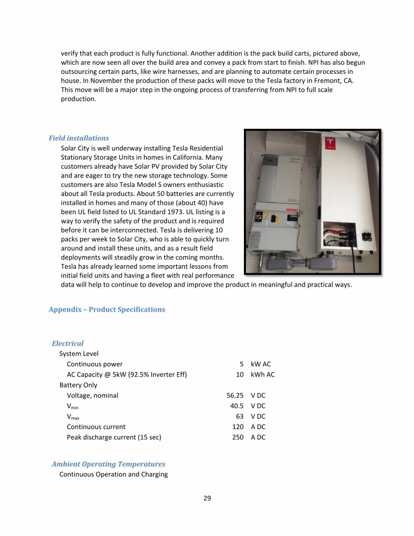
FieldinstallationsSolar City is well underway installing Tesla Residential Stationary Storage Units in homes in California. Many customers already have Solar PV provided by Solar City and are eager to try the new storage technology. Some customers are also Tesla Model S owners enthusiastic about all Tesla products. About 50 batteries are currently installed in homes and many of those (about 40) have been UL field listed to UL Standard 1973. UL listing is a way to verify the safety of the product and is required before it can be interconnected. Tesla is delivering 10 packs per week to Solar City, who is able to quickly turn around and install these units, and as a result field deployments will steadily grow in the coming months. Tesla has already learned some important lessons from initial field units and having a fleet with real performance data will help to continue to develop and improve the product in meaningful and practical ways.
Appendix–ProductSpecifications
ElectricalSystem Level
Continuous power 5 kW AC
AC Capacity @ 5kW (92.5% Inverter Eff) 10 kWh AC
Battery Only
Voltage, nominal 56.25 V DC
Vmin 40.5 V DC
Vmax 63 V DC
Continuous current 120 A DC
Peak discharge current (15 sec) 250 A DC
AmbientOperatingTemperaturesContinuous Operation and Charging

30
Low Operating Temp 10 ⁰C
High Operating Temp 40 ⁰C
De‐rated operation above 40 ⁰C
Discharging
Low Operating Temp ‐20 ⁰C
High Operating Temp 40 ⁰C
Efficiency C/2 C/4
DC (battery only), roundtrip 96% 98%
AC (including inverter), roundtrip 81% 85%
Backup/off‐gridcapabilityAutomatic backup / off‐grid functionality
Provides 1 week of backup power for an energy star refrigerator
Potentially unlimited backup capability if used with solar
MechanicalandMountingHeight x Width x Depth: 1167mm x 484mm x 417 mm
Weight: 168 kg
Wall Mount
Indoor enclosure NEMA 1 rated
RegulatoryUL listing expected to UL 1973

31
3.2DeployintegratedFirmPV/high‐voltagestoragesystems
IntroductionTask 3.2 focused on field implementation by SolarCity of the technology developed by Tesla in task 3.1.
The experience SolarCity gained during the lead acid pilots discussed in task 2.1 informed many of the
design and deployment decisions for the li‐ion projects. Although there were some hurdles with
permitting, inspection, and interconnection, all six sites were successfully deployed and are providing
value in both the residential and commercial use cases.
Although a significant portion of system cost is driven by the cost of the battery pack, the costs of
balance of system and installation are significant enough to make or break the economics of adoption.
This task was important in helping to drive down these costs as well as to test the field performance of
the technology.
Subtask1–SelectCandidateSites
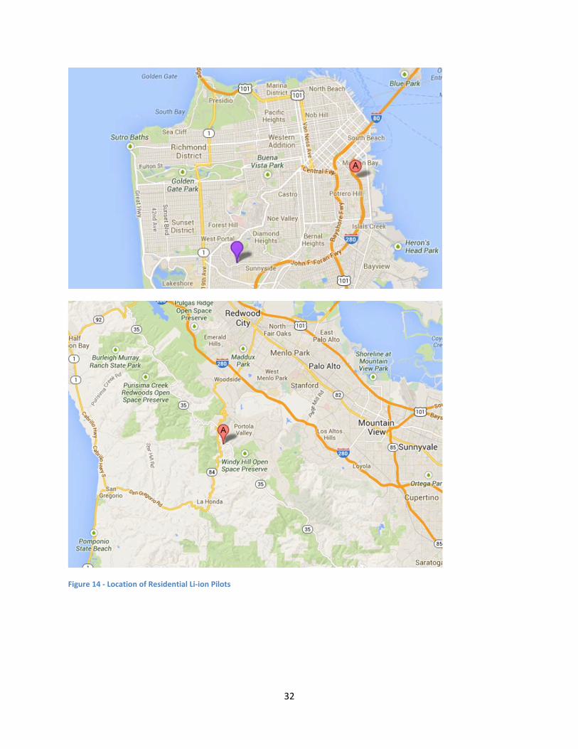
Residential‐SanFranciscoandWoodsideTwo of the residential li‐ion pilot sites were located in San Francisco and one was located in Woodside.
Like the lead acid pilots, these sites were located in Pacific Gas and Electric territory. The AHJs were the
City of San Francisco with whom SolarCity had worked on one of the previous pilots, and the city of
Woodside, which simplified the permitting process. One site was located at a home that had a relatively
small electrical load so the battery system was designed to provide backup to the entire home, while at
the other pilot sites only selected loads were connected to the battery system.
One of the primary challenges with the lead acid pilot installations was the amount of physical space
required for the battery, inverter/charger, and autotransformers, in addition to the equipment and
space needed for the PV installation. The design of the li‐ion system focused on a product that could be
relatively compact and wall mounted. This factor and the elimination of the need for autotransformers
made selecting an installation surface much easier. Locating the systems near both the main electrical
panel and the critical loads was the biggest constraint but both residential systems were successfully
mounted on the garage walls of the two sites.
32
Figure 14 ‐ Location of Residential Li‐ion Pilots
33
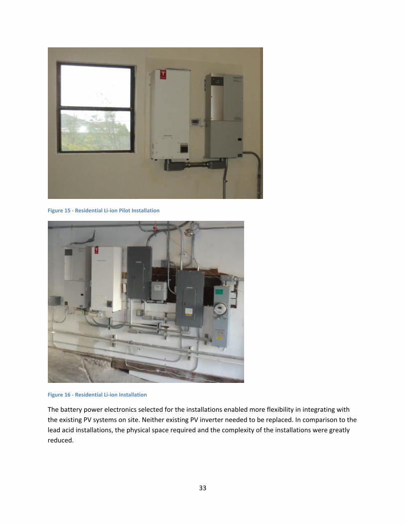
Figure 15 ‐ Residential Li‐ion Pilot Installation
Figure 16 ‐ Residential Li‐ion Installation
The battery power electronics selected for the installations enabled more flexibility in integrating with
the existing PV systems on site. Neither existing PV inverter needed to be replaced. In comparison to the
lead acid installations, the physical space required and the complexity of the installations were greatly
reduced.
34
Commercial–NorthernandCentralCaliforniaThe primary goal for the commercial pilots was to demonstrate that li‐ion energy storage systems
coupled with PV could effectively reduce peak demand. Although PV coupled storage can provide many
benefits, peak demand reduction is the primary use case currently incentivized by utility tariffs.
Providing backup power for certain loads can provide value to commercial customers but was not
included as a feature of these systems. Additionally, participation in ancillary services markets which
provides services to the grid is a key future use of the technologies being developed for this pilot.
The two commercial pilot sites were selected from SolarCity’s existing PV customer base. The key
criteria for selection were sites with significant demand charge rates and therefore good candidates to
test the capability of storage to provide demand reduction. Both sites were located at retail stores with
load of between 300 and 600 kW. The energy storage devices on these sites were paired with existing
PV systems of 350‐500 kW.
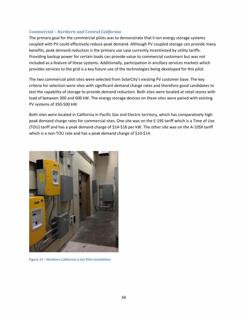
Both sites were located in California in Pacific Gas and Electric territory, which has comparatively high
peak demand charge rates for commercial sites. One site was on the E‐19S tariff which is a Time of Use
(TOU) tariff and has a peak demand charge of $14‐$16 per kW. The other site was on the A‐10SX tariff
which is a non‐TOU rate and has a peak demand charge of $10‐$14.
Figure 17 – Northern California Li‐Ion Pilot Installation

35
Figure 18 – Central California Li‐ion Pilot Installation
Commercial–PennsylvaniaLocationThe other commercial pilot was installed at a commercial location in Pennsylvania. The site was located
in the Pennsylvania Power and Light (PPL) electric utility. This site was similarly geared at peak demand
reduction and designed to be operated in conjunction with a PV system on the same site.
Figure 20 ‐ Pennsylvania Li‐ion Pilot Installation
36
Subtask2–SelectPowerElectronicsThe selection of power electronics for both residential and commercial pilots was informed both by the
lessons learned during the lead acid pilot phase (Task 2.1). Since advanced energy storage technology is
very much still under development, the availability of battery‐enabled power electronics is limited. The
primary manufacturers are Schneider Electric with the XW model, SMA with the Sunny Island (used in
the lead acid pilot installations), and Outback Power’s line of grid‐tied products.
For residential installations, the key selection criteria were a native 120/240 VAC split phase output,
software programmability for integration with the Li‐ion Battery Management System, and device cost.
The SMA Sunny Island was chosen for the first residential Li‐ion installation due to familiarity from the
lead‐acid pilots. For the second two installations, the Schneider XW inverter was chosen due to native
120/240 split phase output.
For commercial installations, a three‐phase, 208 VAC output for integration with the building electrical
system was the most challenging constraint. For this reason, the SMA Sunny Island was chosen for ease
of three‐phase support.
In general, power electronics for integrated PV and energy storage systems are one of the more limiting
factors in further development. Investment in further development of this crucial system component is
a key lever in accelerating the growth of energy storage technologies and deployments.
Subtask3–Audit,Design,andPermitSystemsWith selection of sites and equipment completed, the next step was to audit each site to determine
specific site constraints that would determine the system design. For the residential systems the
concerns were similar to the lead acid pilot phase. Although the li‐ion systems were significantly more
compact and could be fully wall‐mounted, it was still necessary to select a mounting location with at
least 48” of horizontal wall space. Selection of critical backup loads was another key concern.
The first pilot had small enough loads, measured and verified for code compliance purposes, that it was
possible to back up the entire home. Rather than having to pull loads from the main panel or from
indoor subpanels, the home, the PV and the battery system were all relatively easily integrated. All
equipment was located in the garage.
The second residential pilot site had plenty of internal mounting space in the garage. However, the
electrical system was more complicated, including a load center in the garage and one inside the home
on an upstairs floor. Although the whole home could not be backed up, a load monitoring device was
placed on the subpanel to verify that the complete subpanel could be supplied by the storage system.
After a month of data collection, the subpanel was verified to have a low enough draw that it could be
wholly wired in to the energy storage system.
37
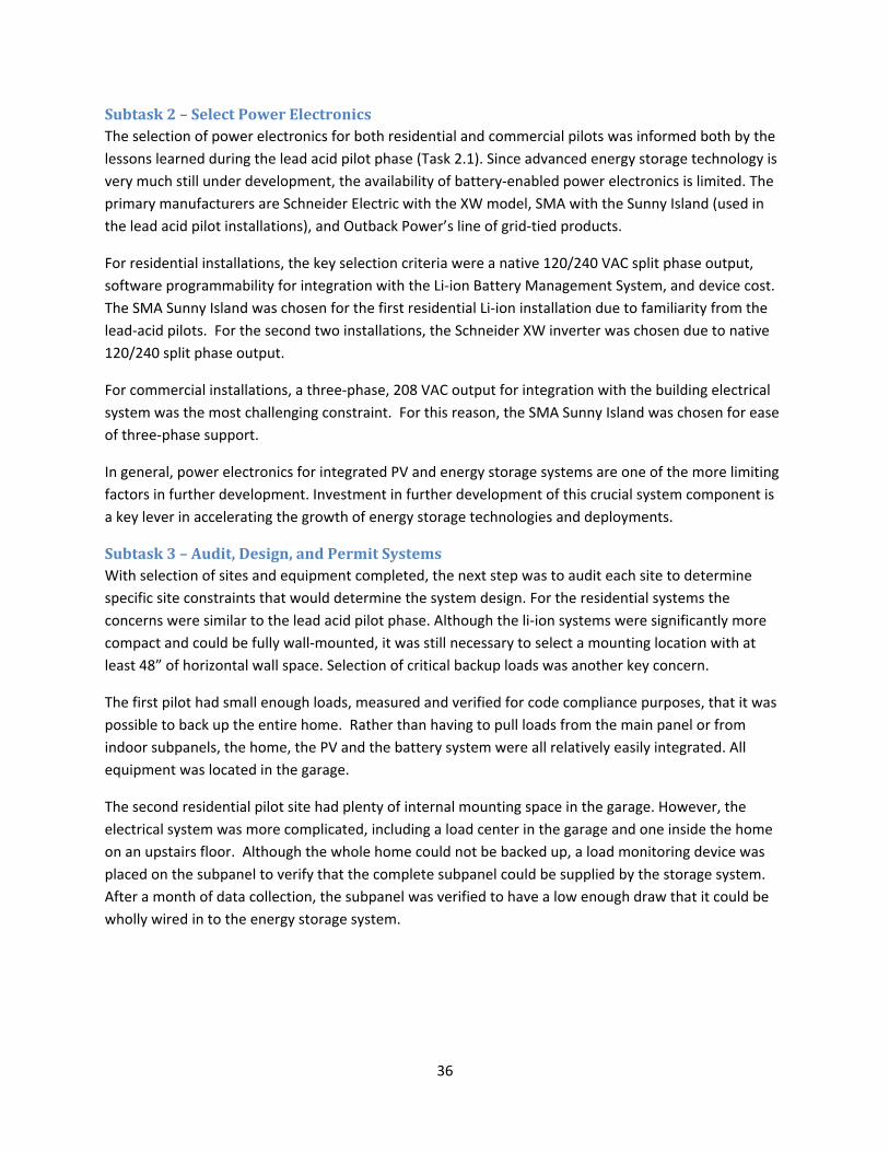
Figure 21 – Residential Pilot 2 System Line Drawing
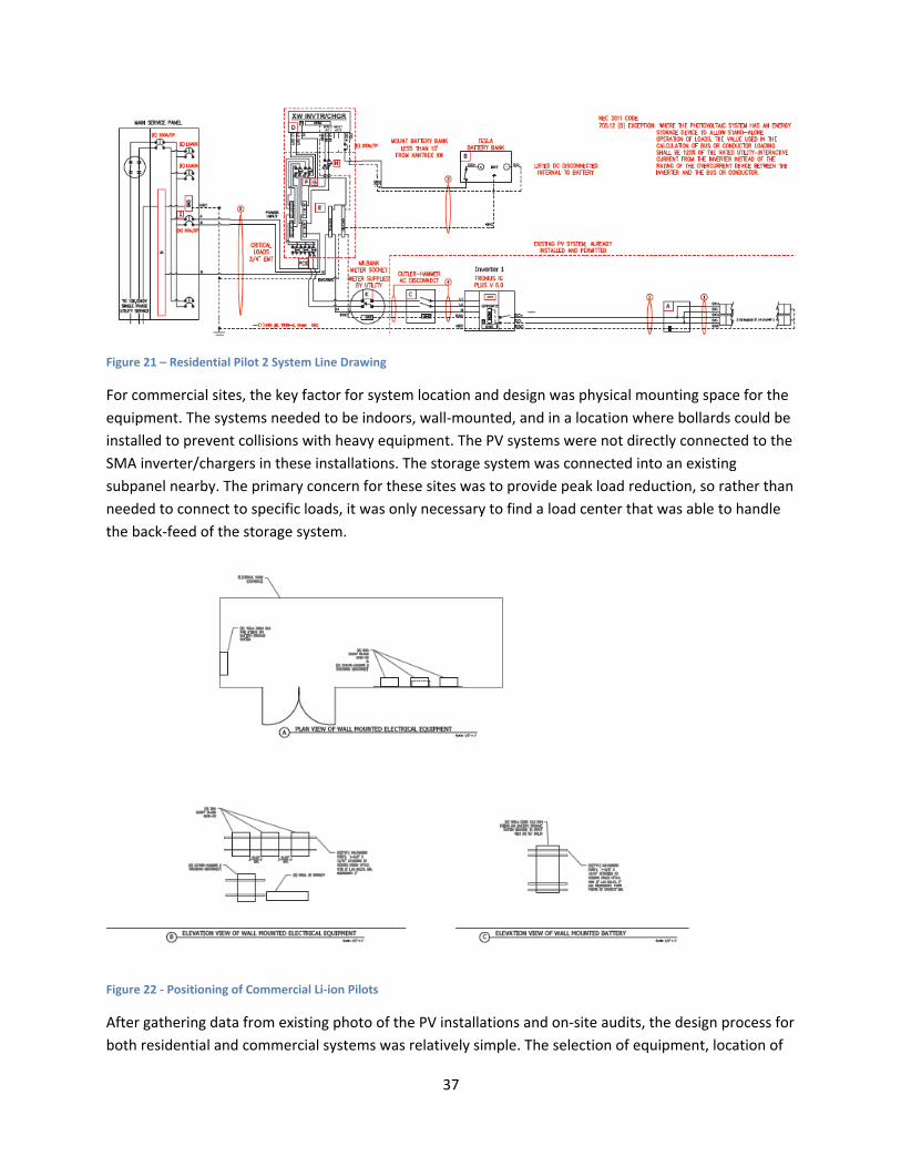
For commercial sites, the key factor for system location and design was physical mounting space for the
equipment. The systems needed to be indoors, wall‐mounted, and in a location where bollards could be
installed to prevent collisions with heavy equipment. The PV systems were not directly connected to the
SMA inverter/chargers in these installations. The storage system was connected into an existing
subpanel nearby. The primary concern for these sites was to provide peak load reduction, so rather than
needed to connect to specific loads, it was only necessary to find a load center that was able to handle
the back‐feed of the storage system.
Figure 22 ‐ Positioning of Commercial Li‐ion Pilots
After gathering data from existing photo of the PV installations and on‐site audits, the design process for
both residential and commercial systems was relatively simple. The selection of equipment, location of

38
equipment, and integration with on‐site electrical system completed, formal plans were created and
submitted to the AHJ’s for each site. Depending on local requirements these plan sets included site
plans, wiring diagrams, load calculations, equipment specification sheets, and structural calculations.
Subtask4–SystemInstallationandInspectionThe residential installations took a single electrician around four work days to install. This included
significant process development and documentation. The installation process began with fixing a
plywood board to the wall studs with lag bolts. The mounting hardware for the battery, inverter/charger
and critical loads panel were mounted to this surface. Due to its weight, the battery was mounted
directly onto two studs. The inverter/charger and integrated critical load panel were lighter and did not
have to be mounted directly into a stud. The battery is then wired to the charge controller and the
inverter is wired to the charge controller as well.
Figure 193 ‐ Mounting the Residential Li‐ion System
Once the major equipment was mounted, the PV output then had to be intercepted and diverted into
the critical load panel for charging the battery and powering critical loads in an off‐grid scenario. One
other requirement from utilities was to add a Net Generation Output Meter (NGOM) onto the PV circuit
to measure PV generation and ensure that Net Energy Metering (NEM) export credit was not given to
battery discharge.
39
The next step was then to wire in the critical loads. For the two residential pilots, the fact that it was
possible to back up an entire panel made the integration of critical loads much easier than it would have
otherwise been. In this case, a 60A breaker was installed in the critical load panel and the load center
was wired into this breaker.
The commercial installations required a scheduled shutdown at each site. Given that they are both retail
locations, shutting down power to the whole facility can be difficult and costly. The installation itself was
very similar to the residential systems with the exception of wiring critical loads or a PV circuit directly
into the system.
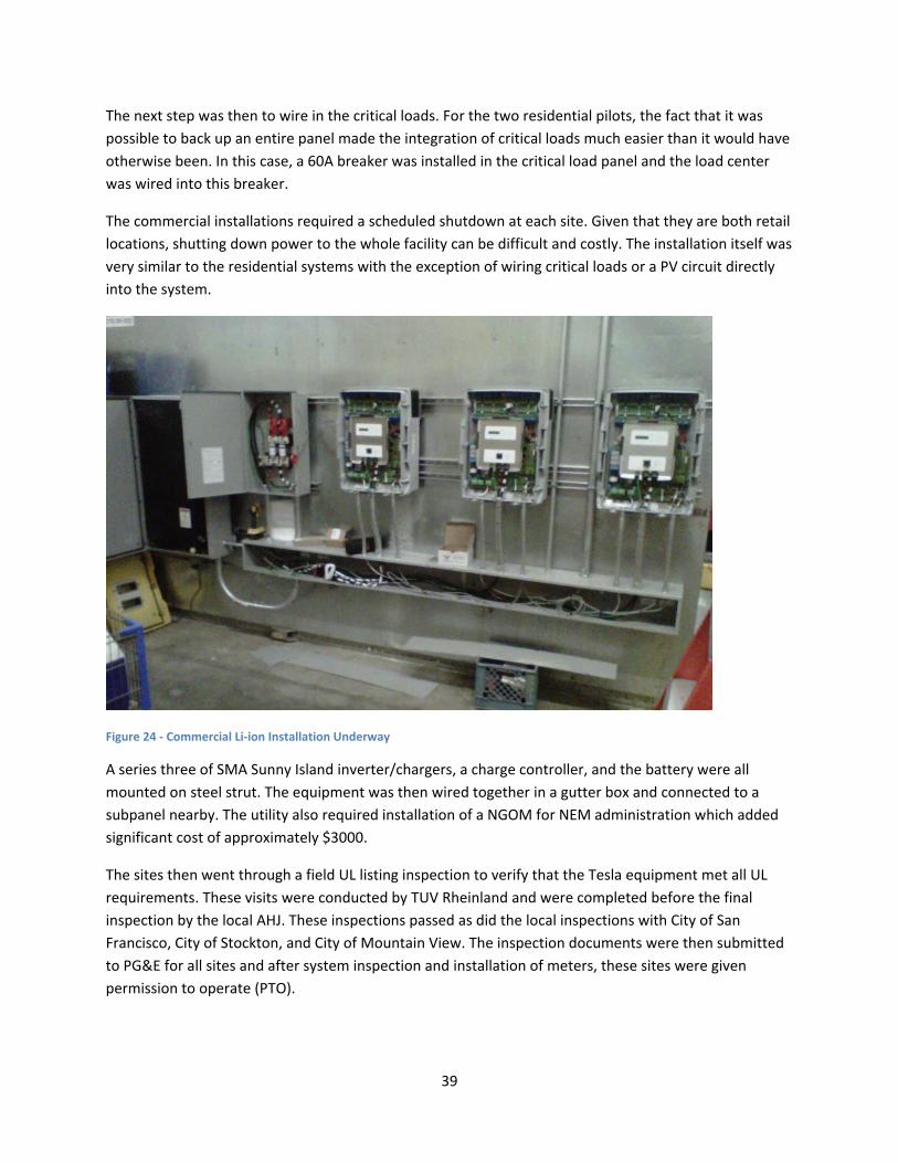
Figure 24 ‐ Commercial Li‐ion Installation Underway
A series three of SMA Sunny Island inverter/chargers, a charge controller, and the battery were all
mounted on steel strut. The equipment was then wired together in a gutter box and connected to a
subpanel nearby. The utility also required installation of a NGOM for NEM administration which added
significant cost of approximately $3000.
The sites then went through a field UL listing inspection to verify that the Tesla equipment met all UL
requirements. These visits were conducted by TUV Rheinland and were completed before the final
inspection by the local AHJ. These inspections passed as did the local inspections with City of San
Francisco, City of Stockton, and City of Mountain View. The inspection documents were then submitted
to PG&E for all sites and after system inspection and installation of meters, these sites were given
permission to operate (PTO).

40
Subtask5–TestCompletedSystemsOnce PTO was received, each installation was then tested for performance. The equipment was tested
to ensure that it was functional and up to the expected specifications. More importantly, the use cases
were tested for backup purposes and load shifting on the residential side and for peal load reduction on
the commercial side.
Market Type Nameplate Capacity Efficiency Power Electronics Battery Type
Residential 5kW AC 10kWh 80% SMA Sunny Island Li‐Ion
Commercial 9kW AC 18kWh 78% Xantrex XW Li‐Ion
ConclusionThe key goal of the deployment in this phase was to prove the field viability of the products that Tesla
developed in Task 3.1. This task demonstrated several benefits of li‐ion technology over the more
traditional lead acid equipment discussed in section 2.1. The newly developed energy storage systems
from Tesla enormously improved ease of installation due to decreased equipment size and weight. The
ability of li‐ion systems to perform over a long timescale and the lack of required maintenance is a key
enabler of commercialization of energy storage. There were still several key challenges to deployment
including inconsistent interconnection policy and limitation of power electronics options. However, the
deployment in task 3.2 was largely successful and created a product and process that can be replicated
at scale.