grepos: a genesis database repositioning programgsjaardema.github.io/seacas/grepos.pdf ·...
TRANSCRIPT

SAND 90-0566 RevisedUnlimited ReleasePrinted June 1993
Supersedes SAND90-0566 dated April 1990Last Modified 5/20/98
GREPOS:A Genesis Database
Repositioning ProgramVersion 1.21, 1998/12/08 (exodus 1)
Version 1.11, 1999/10/18 (exodus 2)
Gregory D. SjaardemaEngineering and Manufacturing Mechanics
Sandia National LaboratoriesAlbuquerque, New Mexico 87185
Abstract
GREPOS is a mesh utility program that repositions or modifies theconfiguration of a two-dimensional or three-dimensional mesh.GREPOS canbe used to change the orientation and size of a two-dimensional or three-dimensional mesh; change the material block, nodeset, and sideset IDs; or“explode” the mesh to facilitate viewing of the various parts of the model.GREPOS also updates theEXODUS quality assurance and information recordsto help track the codes and files used to generate the mesh.GREPOS reads andwrites two-dimensional and three-dimensional mesh databases in theGENESIS database format; therefore, it is compatible with the preprocessing,postprocessing, and analysis codes in the Sandia National Laboratories
DistributionCategory UC-405

Intentionally Left Blank
4

Contents
1 Introduction ......................................................................................................71.1 Modifications Since First Printing ..............................................................71.2 Modifications Since Second Printing ..........................................................71.3 SEACAS Mesh Generation Toolbox ..........................................................81.4 Introduction to the GENESIS File Format ................................................101.5 Overview of Capabilities in GREPOS ......................................................101.6 Organization of Report .............................................................................11
2 Command Input .............................................................................................132.1 Mesh Orientation ......................................................................................142.2 Modification of Attributes or Material, Nodeset, or Sideset IDs ..............192.3 Information and Processing ......................................................................212.4 Order of Transformation ...........................................................................22
3 GREPOS Example Input and Output ..........................................................25
4 Informational and Error Messages ..............................................................27
5 References .......................................................................................................29
A The GENESIS Database Format ..................................................................31
B Command Summary ......................................................................................33
C GREPOS Details ............................................................................................37
5

Intentionally Left Blank
6

wo-nstem
hasAS
ded to
dded tomd toting
argin
1 Introduction
GREPOS is a mesh utility program that repositions or modifies the configuration of a tdimensional or three-dimensional mesh.GREPOS is one of the mesh generation tools ithe Sandia National Laboratories Engineering Analysis Code Access Sy(SEACAS) [1].
1.1 Modifications Since First Printing
This document is a revised version of SAND90-0566 printed April 1990. Chapter 1been completely rewritten to more closely integrate the report with the other SEACmesh generation documentation. The following additional commands have been adGREPOS since that printing:
• INCREMENT, ADJUST, RANDOMIZE, SMOOTH, SWAP, and LIMITS
The following commands have additional options:
• LIST: Added the optionsSSETS, NSETS, INFORMATION, andQA
• DELETE: Added the optionsQAINFO, NSETS, andSSETS
• CHANGE: Added the optionsTYPE, NSETS, andSSETS
The new commands and options are discussed in Chapter 2. Chapter 3 has been aprovide usage examples forGREPOS. Chapter 4 (formerly Chapter 3) is unchanged frothe previous report, and the information formerly in Chapter 4 has been moveAppendix C which has been updated to reflect the move of the primary compuenvironment from VMS/CTSS centered to Unix centered.
1.2 Modifications Since Second Printing
The following commands have been added toGREPOS since the second printing:
• SNAP (page 18)
• WARP (page 19)
• EXECUTE (page 21)
• MOVE (page 14)
• COMBINE (page 20)
• EQUIVALENCE (page 21)
The following commands have had additional options added:
• ADJUST: Added the optionCENTER. (page 14)
This version of the document has not yet been published. Change bars in the left mindicate modifications since the second printing*.
7

n
fthat
below,
e
1.3 Sandia Engineering Analysis Code Access System Mesh GeneratioToolbox
GREPOS is typically used with the other SEACAS mesh generation codesFASTQ [2],GEN3D [3], GENSHELL [4], GJOIN [5], andAprepro [6]. Figure 1 shows the structure othe SEACAS mesh generation toolbox. The basic premise underlying this toolbox iscomplicated geometries can be generated using a set of small specialized codes.
Each of these codes has a specialized purpose, a short synopsis of each code is givenfor more information consult the referenced documentation.
GEN3D Transforms a two-dimensionalGENESIS database into athree-dimensionalGENESIS database. Severaltransformations are supported and additionaltransformations can be easily added.[3]
GREPOS Transforms the geometry of aGENESIS database by scaling,mirroring, offsetting, or rotating. It can also modify thedatabase by deleting or renaming material blocks, sidesetidentifications, or nodeset identifications.[7]
* Some of the change bars are due to internal FrameMaker changes and do not actually indicatchanges in text. These "false" changes are typically associated with cross-references.
Figure 1. Schematic of SEACAS Mesh Generation Process
MAKE
PATRANFASTQ
3D GENESIS
PATRAN
GEN3D
GJOIN GJOINGREPOS
FASTQ BLOT
2D GENESIS
ApreproAprepro Analysis
INPUT FILES
GREPOS
8

meshfrom
ed ofonal
agingblems
dhis
f the
Theatiblehich
GJOIN Join together two or moreGENESIS databases into a singleGENESIS database.[5]
FASTQ Interactive two-dimensional finite element mesh generationprogram. Includes several mesh generation optionsincluding paving.[2]
APREPRO An algebraic preprocessing program which is used toparameterize finite element analyses. Includes a unitconversion system and material database access routines.[6]
GENSHELL Transforms a two-dimensionalGENESIS database into athree-dimensional shellGENESIS database. Severaltransformations are supported and additionaltransformations can be easily added.[4]
NUMBERS Calculates several properties of anEXODUS file, includingmass properties, timesteps, condition numbers, cavityvolumes, and others.[8]
BLOT The primary graphical two-dimensional and three-dimensional postprocessing code. It includes deformed meshplots, contour plots, shaded fringe plots, variable versusvariable and time history plots, and distance versus variableplots. [9]
The SEACAS mesh generation toolbox is a simpler approach to three-dimensionalgeneration than the automatic and general-purpose programs that are availablecommercial vendors. Many complicated three-dimensional geometries are composseveral primitives that can be defined in terms of transformations of two-dimensigeometries. Each of the primitives can be meshed usingFASTQ and GEN3D, and thenjoined together usingGJOIN.
This approach does; however, have some inherent difficulties. The biggest being manand synchronizing several related files. For example, the meshes for some large procan require more than one hundred files containingFASTQ, GEN3D, GJOIN, andGREPOSinput files; temporaryGENESIS files; and parameter files. Manually building anmodifying a mesh this complicated is obviously very difficult and time consuming. Tproblem has typically been minimized at SNL through the use of theUNIX* make† programandAprepro. Make is used to build a set of dependencies between the various pieces ofinite element model. The analyst can then change files as needed and simply typemake
mesh to generate the mesh. If the dependencies have been entered correctly,make willrebuild only those portions of the mesh that are affected by the changed file.synchronization problem (that is, ensuring that all of the separate pieces have compdimensions and discretization) is typically solved by creating a few parameter files w
* UNIX is a registered trademark of UNIX Systems Laboratories Inc.† See your UNIX documentation for more information on make. Typically this is done by entering
the commandman 1 make
9

snput
tionalr readh
tiontypescationmore
l ort IDs;y a
les
oing,func-t in
IDs.input(that
an also
f thedden
contain key dimensions and discretization information.Aprepro is then used to preprocesthe input files and insert the key dimensions and discretization information into the ifiles.
1.4 Introduction to the GENESIS File Format
TheGENESIS mesh database file format is the geometry definition portion of theEXODUSdatabase file format used in the Engineering Sciences Center at Sandia NaLaboratories. All of the mesh generation programs in the Engineering Sciences Centeand write files in theGENESIS format, which allows great flexibility in the choice of mesgeneration, file translation, and graphical processing.
TheGENESIS file contains the data to describe a finite element mesh including the locaof the nodal points, the connectivity of the nodes that form each element, the materialof each element, and the boundary condition data which are used to specify load applipoints and nodal constraints. The reader is referred to References [10] and [11] forinformation.
1.5 Overview of Capabilities inGREPOS
With GREPOS, the user can change the orientation and size of a two-dimensionathree-dimensional mesh; change or delete material block, nodeset, and sidese“explode” the mesh to facilitate viewing of the various parts of the model; or applsmoothing process to the generated mesh to produce better shaped elements.GREPOSalso updates theEXODUS QA and information records to help track the codes and fiused to generate the mesh.
Orientation:The orientation of the mesh can be changed by revolving, offsetting, reflecting, zerand scaling the nodal coordinates of the original mesh. A coordinate randomizationtion is available to try to mimic the naturally occurring imperfections that are presenreal-life geometries.
Material Blocks, Sidesets, and Nodesets:In the SEACAS system, material properties are input according to material blockSimilarly, boundary conditions are associated with sideset and nodeset IDs. Thematerial block IDs, sideset IDs, and nodeset IDs can be changed to a new unique IDis they can be changed, but not combined). Material blocks, sidesets, and nodesets cbe deleted.
Mesh “Explosion” for Viewing Multiple Material Meshes:An exploded view generation capability has been implemented inGREPOS. An explodedview is generated by offsetting each material block by a specified distance in each otwo or three coordinate directions. This allows viewing pieces of the mesh that are hiby other pieces.
10

le-tput
of a
Quality Assurance (QA) and Information Records:A QA record for theGREPOS program is added to the input QA record(s), and the finame of the input file is added to the information records that are written to the oumesh. The information record is prefaced byGREPOS to help in identification. Theserecords, which are explained in Reference [10], are useful in tracing the evolutionmesh during the mesh generation process.
1.6 Organization of Report
The remainder of this report is organized as follows:
• Chapter 2 describes the command input and valid commands,
• Chapter 3 presents a few short examples illustratingGREPOS use, and
• Chapter 4 describes the informational and error messages written byGREPOS.
Three appendices are contained in this report.
• Appendix A is a code segment defining theGENESIS binary database format,
• Appendix B is a summary of the commands inGREPOS, and
• Appendix C describes the specifics ofGREPOS including executing it, obtainingit, compiling it, and quality assurance.
11

12

gyntax
re
ters
e is
r of
mayother
meterslue is
e iner
n
s
mma
2 Command Input
The user directs the execution ofGREPOS by entering commands to set processinparameters. The commands are in free-format and must adhere to the following srules.
• Valid delimiters are a comma or one or more blanks.
• Either lowercase or uppercase letters are acceptable, but lowercase letters aconverted to uppercase.
• A “$” character in any command line starts a comment. The “$” and any characfollowing it on the same line are ignored.
• A command may be continued over several lines with an “* ” character. The “* ”and any characters following it on the current line are ignored and the next linappended to the current line.
Each command has an action keyword or “verb” followed by a variable numbeparameters.
An action keyword or verb is a character string matching one of the valid commands. Itbe abbreviated as long as enough characters are used to distinguish it fromcommands.
The meaning and type of the parameters depend on the command verb. Most paraare optional. If an optional parameter field is blank, a command-dependent default vasupplied. Valid entries for parameters are:
• A numeric parameter may be a real number or an integer. A real number may bany legal FORTRAN numeric format (e.g., 1, 0.2, -1E-2). An integer paramet
may be in any legal integer format*.
• A string parameter is a literal character string. Most string parameters may beabbreviated.
The notation conventions used in the command descriptions are:
• The command verb is in bold type.
• A literal string is in all uppercaseSANSERIF type and should be entered as show(or abbreviated).
• The value of a parameter is represented by the parameter name initalics.
• A literal string in square brackets (“[ ]”) represents a parameter option which iomitted entirely (including any following comma) if not appropriate. Theseparameters are distinct from most parameters in that they do not require a co
* Arithmetic equations, variables, and control structures can be used in the input files if the-aprepro option is used. See the Aprepro manual for more information.
13

f anitial
as a place holder to request the default value.
• The default value of a parameter is in angle brackets (“< >”). The initial value oparameter set by a command is usually the default parameter value. If not, the isetting is given in the command description.
2.1 Mesh Orientation
ADJUST MINIMUM|MAXIMUM|CENTER axis1,value
1,…
ADJUST calculates the required offset such that the specified minimum,maximum, or bounding box center X, Y, or Z coordinate in the generated meshis equal tovalue (ignoring any other mesh orientation commands). Only oneminimum, maximum, or center per coordinate axis can be specified. The lastspecification for each coordinate axis is retained if theADJUST command is usedmultiple times. The center is defined to be the center of the bounding box of themodel.
TheOFFSET RESET will cancel theADJUST command.
EXPLODE <no parameters>
EXPLODE initiates an input mode whereGREPOS prompts for the coordinateoffsets to be applied to each material block. Before performing the material blockoffsets, GREPOS checks for connections between the material blocks. Allconnected material blocks will be assigned the same offset to avoid distorting themesh. An informational message will be output to the standard output device foreach connected material block.
MIRROR axis1, axis
2,… <No Default>
MIRROR RESET <no reflections>
MIRROR causes the mesh to be reflected about a coordinate plane. Eachaxisparameter specifies which coordinates (X or Y or Z) will be modified. Reflectionsare performed after the mesh has been repositioned by theREVOLVE andOFFSET commands.
TheMIRROR RESET command resets to no reflection.
Reflections are not cumulative, that is, ifMIRROR X Y Y X is entered, only one Xand Y reflection will be performed. The element connectivity and the sideset facenumbering will be correctly reordered.
MOVE slave_sideset_idTO master_sideset_id[X|Y|Z|MINUSX|MINUSY|MINUSZ] [TOLER tolerance] MAXDELTA maxdelta [GAP gap]
14

t
t
y
ce
eet
eit
t
MOVE slave_sideset_idTO master_sideset_id [VECTOR vx vy vz] [TOLER tolerance] MAXDELTA maxdelta [GAP gap]
MOVE moves the nodes in all element blocks connected to the sideset specifiedby slave_sideset_idthe minimum distance required such that a node inslave_sideset_idtouches an element face of the sideset specified bymaster_sideset_id. The nodes are moved in the direction specified by thedisplacement vector. Several options are available for specifying the displacemenvector of the slave nodes. The optionsX, Y, Z, MINUSX, MINUSY, andMINUSZspecify the displacement vector as the respective coordinate direction. An explicidisplacement vector can be specified if theVECTOR option is entered.
The TOLER option is used to specify how close to the master element face theslave vector must be to detect a match. If a slave node does not intersect anelement face within the specified tolerance, the maximum tolerance required fora match is output.
TheMAXDELTA option specifies the maximum distance that a node can be movedto move it to the master surface. This is needed in cases where the master surfafolds back on itself and more than one intersection point is possible (e.g. a tire).The maxdelta distance defaults to 1.0e15 if not entered.
The GAP option specifies the distance between the slave sideset nodes and thmaster_sideset_id element faces. If GAP=0.0, then the closest node on the sidesspecified by slave_sideset_idwill lie directly on an element face of themaster_sideset_idsideset. If GAP<0.0, then the node will penetrate amaster_sideset_id element face, and if GAP>0.0, then the minimum distancebetween the master and slave sidesets will equal the specified gap distance. Thspecified gap distance is applied after the search phase of the algorithm, sodoesn’t affect theMAXDELTA or displacement vector.
OFFSET [ADD] axis1, offset
1, axis
2, offset
2, …
OFFSET [ADD] ALL offset <0.0>OFFSET RESET <initial condition>OFFSET xoff <0.0,>yoff <0.0,>zoff <0.0>
OFFSET specifies offsets to be added to the coordinates. If aREVOLVE commandhas been issued, the mesh is rotated before it is offset. The last form of the offsecommand is included to maintain compatibility with the offset command inGEN3D.
OFFSET ALL offsets all of the coordinates by the specified offset, andOFFSETRESET resets the offsets to zero.
If the optional keywordADD is specified, offsets are cumulative, that is, ifOFFSET ADD X 0.5 X 1.0 is entered, the \axis X coordinates will be offset by 1.5.If ADD is omitted from the above line, the \axis X coordinates will be offset by 1.0.
15

t
s
OFFSET SPLINE
OFFSET SPLINE is a special form of theOFFSET command in which the offsetsin the X and Y coordinates are given in terms of a spline curve as a function of theZ coordinate.OFFSET SPLINE initiates an input mode in which the spline curveis defined. Valid commands in this input mode are:
BOTTOM xslope yslope- the slope at the minimum Z coordinate of the curveBACK xslope yslope- the slope at the minimum Z coordinate of the curveTOP xslope yslope- the slope at the minimum Z coordinate of the curveFRONT xslope yslope- the slope at the minimum Z coordinate of the curvezcord, xcord, ycord- points defining the curve, must be entered from minimum Zto maximum Z.LIST COMMANDS - list valid commands in spline input mode.EXIT or END - terminate spline input mode.
This command can only be used with three-dimensionalGENESIS files.
RANDOMIZE axis1, magnitude
1, axis
2, magnitude
2, …
RANDOMIZE ALL magnitude <0.0>RANDOMIZE RESET <initial condition>RANDOMIZE BLOCK <no parameters>
RANDOMIZE specifies random offsets to be added to the coordinates. If aREVOLVE command has been issued, the mesh is rotated before it is offset. Thespecified coordinates are offset by a random amount in the range from -magnitudeto +magnitude.
RANDOMIZE ALL randomly offsets all of the coordinates by the specifiedmagnitude, andRANDOMIZE RESET cancels the offsets.
RANDOMIZE BLOCK initiates an input mode whereGREPOS prompts for themagnitudes of the random offsets to be applied to each material block. Beforeperforming the material block offsets,GREPOS checks for connections betweenthe material blocks. All connected material blocks will be assigned the same offseto avoid distorting the mesh. An informational message will be output to thestandard output device for each connected material block.
If there are contact surfaces in the mesh description, the nodes on both surfacewill be moved using a different random offset; therefore, if the two surfaces areinitially in contact, it is almost certain that they will overlap after they are offset.
REVCEN xcen< 2D minimum X coordinate,>ycen< 2D minimum Y coordinate,>zcen<0.0 (three-dimensional mesh)>
REVCEN sets the center of revolution for theREVOLVE command to the point(xcen, ycen, zcen).
16

f
REVOLVE axis1, ndeg
1, axis
2, ndeg
2, … <last selection >
REVOLVE RESET <initial condition>
REVOLVE causes the mesh to be rotated. Each (axisi, ndeg
i) parameter pair
specifies an axis (X or Y or Z) and the number of degrees to rotate. The rotationsare according to right-hand rule. The center of the rotation is specified by theREVCEN command.
The rotations are according to right-hand rule. The center of the rotation isspecified by theREVCEN command.
Revolutions are cumulative and order-dependent; however, only one center orevolution (seeREVCEN) may be specified. TheREVOLVE RESET commandresets to no rotation.
For a two-dimensional mesh,axisi must beZ.
SCALE axis1, scale
1, axis
2, scale
2, …
SCALE ALL scale_factor<1.0 >SCALE RESET <initial condition>
SCALE causes the specified coordinates of axisaxisito be multiplied by the
scaling multiplierscalei. The scaling multiplier must be greater than zero; the
MIRROR command must be used with theSCALE command if a negative scalingmultiplier is required. For example,SCALE X 2.54 MIRROR X will scale the Xcoordinates by -2.54.
SCALE ALL multiplies all of the coordinates by the specified multiplier, andSCALE RESET resets to no scaling.
Scalings are cumulative, that is, ifSCALE X 0.5 X 0.6 is entered, theX coordinateswill be scaled by 0.3.
SCALE ATTRIBUTE numberBLOCK id scale_factorSCALE ATTRIBUTE ALL BLOCK id scale_factorSCALE ATTRIBUTE numberBLOCK ALL scale_factorSCALE ATTRIBUTE ALL BLOCK ALL scale_factorSCALE ATTRIBUTE RESET
SCALE ATTRIBUTE causes the specified attribute of the specified element blockto be multiplied by the scaling multiplierscale_factor.
SCALE ATTRIBUTE ALL multiplies all of the attributes of the specified elementblock by the specified multiplier, andSCALE ATTRIBUTE numberBLOCK ALLscales the specified attribute of all element blocks (with attributes).
SCALE ATTRIBUTE RESET resets all attribute scale factors to 1.0
Attribute scalings are not cumulative.
17

tontl
s
SCALE BLOCK
SCALE BLOCK initiates an input mode whereGREPOS prompts for the scalefactor to be applied to the nodal coordinates of each material block. Beforeperforming the material block scaling,GREPOS checks for connections betweenthe material blocks. All connected material blocks will be assigned the samescaling to avoid distorting the mesh. An informational message will be output tothe standard output device for each connected material block.
SHIFT [ADD] axis1, shift
1, axis
2, shift
2, …
SHIFT [ADD] ALL shift <0.0>SHIFT RESET <initial condition>SHIFT xoff <0.0,>yoff <0.0,>zoff <0.0>SHIFT SPLINE
SHIFT is simply a synonym for theOFFSET command. See the description of theOFFSET command for more information.
SMOOTH tolerance<1.0E-6>, iterations<100>, relax<1.0>
SMOOTH performs a length-weighted Laplacian smoothing using Gauss-Siedeliterations [2] which moves a node along a vector sum of weighted factors from thenode to nearest neighbor nodes. The weighting is based on the relative distancethe neighboring nodes. Nodes on material boundaries are moved along the tangeto the boundary, and corner nodes are not moved. The iterations will continue untieither the maximum node movement in one iteration is less thantolerance, or untilthe iterations exceediterations.
SNAP slave_sideset_idTO master_sideset_id[NORMAL|X|Y|Z|MINUSX|MINUSY|MINUSZ] [TOLER tolerance] MAXDELTA maxdelta
SNAP slave_sideset_idTO master_sideset_id [VECTOR vx vy vz] [TOLER tolerance] MAXDELTA maxdelta
SNAP slave_sideset_idTO master_sideset_id [CENTER cx cx cz] [TOLER tolerance] MAXDELTA maxdelta
SNAP adjusts the positions of the nodes on the sideset specified byslave_sideset_idto lie on the element faces of the sidesetmaster_sideset_id.Several options are available for specifying the displacement vector of the slavenodes. The default option isNORMAL. In this case, the slave node normal iscalculated as the average of the element face normals for all element faceconnected to the slave node. The optionsX, Y, Z, MINUSX, MINUSY, andMINUSZ specify the displacement vector as the respective coordinate direction.An explicit displacement vector can be specified if theVECTOR option is entered.The last option is to specify a radial displacement vector originating from thespecifiedCENTER location.
18

y
ce
ff
e
r
e
The TOLER option is used to specify how close to the master element face theslave vector must be to detect a match. If a slave node does not intersect anelement face within the specified tolerance, the maximum tolerance required fora match is output.
TheMAXDELTA option specifies the maximum distance that a node can be movedto snap it to the master surface. This is needed in cases where the master surfafolds back on itself and more than one intersection point is possible (e.g. a tire).The maxdelta distance defaults to 1.0e15 if not entered.
WARP XAXIS|YAXIS|ZAXIS|ORIGIN RADIUS radius NORMAL X|Y|Z
WARP takes an input 3D mesh and warps (or wraps) it around the specified axis.The RADIUS value is the 'reference radius' which means a plane in the originalmesh a distance of 'radius' from the specified axis will be mapped into the newspace with no stretching or shrinking. Planes farther from the axis will bestretched, closer to the axis will be shrunk.
TheNORMAL along with the warping axis specify another plane. The new and oldcoordinates of the mesh nodes lying on this plane will be equal. The normal alsospecifies the 'zero angle' or origin of the angle space for the mapping.
ZERO axis1, min
1, axis
2, min
2, …
ZERO RESET <no automatic zeroing>
ZERO sets allaxisicoordinates with an absolute value less thanmin
iequal to zero.
The ZERO RESET command resets to no automatic zeroing. This command isused to zero nodal coordinates that should be equal to zero, but due to roundoerrors they have slightly nonzero values.
2.2 Modification of Attributes or Material, Nodeset, or Sideset IDs
CHANGE MATERIAL|NODESET|SIDESET|NSETS|SSETS old_id new_idCHANGE TYPE block_id new_type
CHANGE changes the identification numberold_id of a material block, nodeset,or sideset tonew_id. Thenew_idmust be unique, that is,CHANGE can only beused to change the identification number; it cannot be used to combine or deletidentification numbers (useGJOIN to combine material blocks, sidesets, ornodesets).
CHANGE TYPE changes the element type of the specified material block to thespecified type. For example,CHANGE TYPE 1 SHELL changes the element typeof material block 1 toSHELL. Note that only the identification of the element typeis changed. This command does not change the connectivity or any othedescriptor of the element block. Valid identifiers for element types are analysiscode dependent; consult the documentation for the target analysis code for morinformation.
19

r
n
e
CHANGE ATTRIBUTE numberBLOCK id valueCHANGE ATTRIBUTE ALL BLOCK id valueCHANGE ATTRIBUTE numberBLOCK ALL valueCHANGE ATTRIBUTE ALL BLOCK ALL valueCHANGE ATTRIBUTE RESET
CHANGE ATTRIBUTE causes the specified attribute of the specified elementblock to be set tovalue.
CHANGE ATTRIBUTE ALL sets the value of all of the attributes of the specifiedelement block to the specified value, andCHANGE ATTRIBUTE numberBLOCKALL sets the specified attribute of all element blocks (that contain attributes).
CHANGE ATTRIBUTE RESET resets all attributes to their original value.
Attribute changing cannot be combined with attribute scaling of the sameattribute.
COMBINE BLOCK id_final WITH BLOCK id1, id2, ..., idnCOMBINE MATERIAL id_final WITH MATERIAL id1, id2, ..., idnCOMBINE NODESET id_final WITH NODESET id1, id2, ..., idnCOMBINE SIDESET id_final WITH SIDESET id1, id2, ..., idn
COMBINE combines the specified entities (element blocks, materials, nodesets, osidesets) into a single entity of the same type with the specified id. An entity withthe specified final id must exist and the other entities are added to this id. Thecombined ids of the entities combined into the final id will not appear in the outputdatabase. There is currently no capability to undo theCOMBINE command.
DELETE MATERIAL|NODESET|SIDESET|NSETS|SSETS idi …
DELETE QAINFO| QA| INFORMATION
DELETE deletes the material block, nodeset, or sideset with IDidi. Multiple IDs
can be deleted on the same line. Note: this command can not be undone, once aID is deleted, it is gone*.
DELETE QAINFO, QA, or INFORMATION deletes theEXODUS quality assurancerecords and information records, only the quality assurance records, or only theinformation records, respectively. After deleting the specified records, a newINFO record is added that documents the deletion†.
* Actually, DELETE sets the ID to zero to flag that the entity is deleted. Therefore, if youCHANGE ID 0 to the original ID number, you can recover deleted materials, nodesets, orsidesets.
† This command is not intended to undermine or in any way reduce the Quality Assurance trailassociated with an analysis. The command was added as a work-around for bugs found in somof the other codes that could only handle a fixed number of QA or INFO records.
20

.
EQUIVALENCE toleranceEQUIVALENCE RESET
EQUIVALENCE results in all nodes in the model that are withtolerancedistanceof each other to be combined into a single node. The equivalencing will beperformed after theEXECUTE or EXIT command is specified. There is currentlyno way to limit the combined nodes based on membership in a nodeset.
EQUIVALENCE RESET removes previous EQUIVALENCE commands and nonodes will be equivalenced.
INCREMENT MATERIAL|NODESET|SIDESET|NSETS|SSETS increment…
INCREMENT increments the identification numbers associated with the materialblocks, nodesets, or sidesets by the specifiedincrementbefore creating the outputGENESIS file. This command cannot be undone once it is entered.
SWAP SIDESET|SSETS id,…
SWAP reverses the direction of the sideset normal. It should only be used onsidesets that are defined on the faces ofSHELL elements.
2.3 Information and Processing
END|EXIT
END or EXIT ends the command input and starts the mesh transformation.
EXECUTE
EXECUTE performs all currently specified transformations and then returns to thecommand handler for additional transformations.
HELP command <general help>
HELP displays information about the program command given as the parameterIf no parameter is given, all the command verbs are displayed. This command issystem-dependent and may not be available on some systems.
LIMITS
LIMITS displays the minimum, maximum, and range of the X, Y, and Zcoordinates of the input mesh.
LIST option
LIST displays information about the requestedoption. Valid options are:VARIABLES, VARS, MATERIAL, BLOCKS, NODESET, NSETS, SIDESET,
21

ede
d
e
ands
Intentionally Left Blank
SSETS, QA, INFORMATION, andCOMMANDS.
LIST {VARS|VARIABLES}
displays a summary of the database. The summary includes the database title; thnumber of nodes, elements, and element blocks; the number of node sets and sisets; and the number of each type of variable.
LIST {BLOCKS|MATERIALS}
displays a summary of the element blocks. The summary includes the blockidentifier, the number of elements in the block, the element number of the first andlast element in the block, and the block status, either selected or not selected.
LIST {NSETS|NODESETS}
displays a summary of the node sets. The summary includes the set identifier anthe number of nodes in the set.
LIST {SSETS|SIDESETS}
displays a summary of the side sets. The summary includes the set identifier, thnumber of elements in the set, and the number of nodes in the set.
LIST {QA|INFORMATION}
displays the quality assurance (QA) records or the information (INFO) recordswhich maintain the history of theGENESIS file.
QUIT
QUIT ends the command input and exits the program immediately without writingan output database.
SHOW command <no parameter>
SHOW displays the settings of parameters relevant to thecommand. For example,the commandSHOW REVOLVE displays information about the currently definedrevolution.
2.4 Order of Transformation
AlthoughGREPOS commands may be entered in any order, processing of the commis performed in the order shown below:
SNAP or MOVE, DELETE, REVOLVE, OFFSET, MIRROR, RANDOMIZE, ZERO,SCALE, EXPLODE, and SMOOTH.
Processing of transformation commands does not occur until anEXECUTE, EXIT or ENDcommand is entered.
22

es to
r
If order-dependent processing is required, theEXECUTE command must be used. ThEXECUTE command performs all currently specified transformations and then returnthe command handler for additional transformations. An example of this follows:
scale x 1.1074executerevolve x 30 y 30executezero x 1.0e-5 y 1.0e-5executescale y 12.5
Unlike the transformation commands, theCHANGE operations are performed in the ordethey are entered, and at the time they are entered.
23

24
esetput
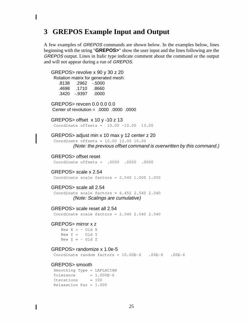
3 GREPOS Example Input and Output
A few examples ofGREPOS commands are shown below. In the examples below, linbeginning with the string "GREPOS>" show the user input and the lines following are thGREPOS output. Lines in Italic type indicate comment about the command or the ouand will not appear during a run ofGREPOS.
GREPOS> revolve x 90 y 30 z 20 Rotation matrix for generated mesh: .8138 .2962 -.5000 .4698 .1710 .8660 .3420 -.9397 .0000
GREPOS> revcen 0.0 0.0 0.0 Center of revolution = .0000 .0000 .0000
GREPOS> offset x 10 y -10 z 13 Coordinate offsets = 10.00 -10.00 13.00
GREPOS> adjust min x 10 max y 12 center z 20 Coordinate offsets = 10.00 12.00 10.00
(Note: the previous offset command is overwritten by this command.)
GREPOS> offset reset Coordinate offsets = .0000 .0000 .0000
GREPOS> scale x 2.54 Coordinate scale factors = 2.540 1.000 1.000
GREPOS> scale all 2.54 Coordinate scale factors = 6.452 2.540 2.540
(Note: Scalings are cumulative)
GREPOS> scale reset all 2.54 Coordinate scale factors = 2.540 2.540 2.540
GREPOS> mirror x z New X = - Old X New Y = Old Y New Z = - Old Z
GREPOS> randomize x 1.0e-5 Coordinate random factors = 10.00E-6 .00E-6 .00E-6
GREPOS> smooth Smoothing Type = LAPLACIAN Tolerance = 1.000E-6 Iterations = 100 Relaxation Par = 1.000
25

GREPOS> list block
Block 1 (#1): 230 elements 4-node 0 attributes Element block type = "QUAD " Block 2 (#2): 52 elements 2-node 0 attributes Element block type = "TRUSS "
Two material blocks in model, IDs are 1 and 2
GREPOS> change material 1 2
ERROR - Cannot change to an existing ID
Material ID 2 already exists in model
GREPOS> change material 1 10 *** Material 1 changed to Material 10
GREPOS> change type 2 BAR *** Material Block 2 type changed to BAR
GREPOS> list
Valid LIST optionsSSETS SIDESETS NSETS NODESETS VARS VARIABLE BLOCKS
MATERIAL COMMANDS INFORMAT QA
GREPOS> limits
Input Mesh Limits: Min X = 0.00000E+00, Max X = 1.20000E+00, Range = 1.20000E+00 Min Y = -1.00000E-01, Max Y = 0.00000E+00, Range = 1.00000E-01 Min Z = 0.00000E+00, Max Z = 2.78000E+00, Range = 2.78000E+00
GREPOS> increment material 10 *** Material 10 changed to Material 20 *** Material 2 changed to Material 12
GREPOS> exitNo more input, process the file.
26

at:
rningmmandthey be
utt of
stem.ple,
thisthan
is tooeases
error
und an
e
4 Informational and Error Messages
GREPOS first reads the input database, which must be a validGENESIS database. If adatabase format error is discovered, the program prints an error of the following form
DATABASE ERROR - Reading database item and aborts.
After the database is read, command input is requested from the user. An error or wamessage may appear in response to a command. If an error message appears, the cois usually ignored. If only a warning is printed, the command is usually performed. Ifmessage is not sufficiently informative, the appropriate command description mahelpful. The display after the command shows the effect of the command.
When the command input is complete,GREPOS transforms the mesh and writes the outpdatabase.GREPOS allocates memory dynamically as it is needed. If the system runs oumemory, the following message is printed:
FATAL ERROR - Too much dynamic memory requested
and the program aborts. The user should first try to obtain more memory on the syAnother solution is to run the program in a less memory-intensive fashion. For examreducing the number of transformations requires less memory.
GREPOS has certain programmer-defined limitations. The limits are not specified inmanual since they may change. In most cases the limits are chosen to be moreadequate. If the user exceeds a limit, a message is printed. If the user feels the limitrestrictive, the code sponsor should be notified so the limit may be raised in future relof GREPOS.
If the user tries to change an element block, sideset, or nodeset ID to an existing ID, anmessage of the form
Cannot change to an existing ID
will be printed and the command will not be performed. TheEXPLODE command checksthat all nodes of the mesh are connected to an element. If a non-connected node is foerror message of the form
Node not connected to any elements
will be output. TheEXPLODE command will be executed. In addition, if two or morelement blocks are connected a message of the form
EXPXYZ – Material id_1 is connected to material id_2
is output and the offset for material blockid_2 is set equal to that for material blockid_1.
27

28

ringional
8–
3Dnal
tionew
ISries,
initeries,
m,”New
ingortrch
teries,
ntndia
itenal
esndia
5 References
[1] G. D. Sjaardema, “Overview of the Sandia National Laboratories EngineeAnalysis Code Access System,” Technical Report SAND92–2292, Sandia NatLaboratories, Albuquerque, New Mexico, January 1993.
[2] T. D. Blacker, “FASTQ Users Manual, Version 2.1,” Technical Report SAND81326, Sandia National Laboratories, Albuquerque, New Mexico, July 1988.
[3] A. P. Gilkey and G. D. Sjaardema, “GEN3D: A GENESIS Database 2D toTransformation Program,” Technical Report SAND89-0485, Sandia NatioLaboratories, Albuquerque, New Mexico, March 1989.
[4] G. D. Sjaardema, “GENSHELL: A GENESIS Database 2D to Shell TransformaProgram,” technical report, Sandia National Laboratories, Albuquerque, NMexico. In preparation.
[5] G. D. Sjaardema, “GJOIN: A Program for Merging Two or More GENESDatabases,” Technical Report SAND92-2290, Sandia National LaboratoAlbuquerque, New Mexico, December 1992.
[6] G. D. Sjaardema, “Aprepro: An Algebraic Preprocessor for Parameterizing FElement Analyses,” Technical Report SAND92–2291, Sandia National LaboratoAlbuquerque, New Mexico, December 1992.
[7] G. D. Sjaardema, “GREPOS: A GENESIS Database Repositioning PrograTechnical Report SAND90-0566, Sandia National Laboratories, Albuquerque,Mexico, April 1990.
[8] G. D. Sjaardema, “NUMBERS: A Collection of Utilities for Pre- and PostprocessTwo- and Three-Dimensional EXODUS Finite Element Models,” Technical RepSAND88–0737, Sandia National Laboratories, Albuquerque, New Mexico, Ma1989.
[9] A. P. Gilkey, “BLOT—A Mesh and Curve Plot Program for the Output of a FiniElement Analysis,” Technical Report SAND88–1432, Sandia National LaboratoAlbuquerque, New Mexico, June 1989.
[10] W. C. Mills-Curran, A. P. Gilkey, and D. P. Flanagan, “EXODUS: A Finite ElemeFile Format for Pre- and Post-processing,” Technical Report SAND87–2977, SaNational Laboratories, Albuquerque, New Mexico, September 1988.
[11] L. M. Taylor, D. P. Flanagan, and W. C. Mills-Curran, “The GENESIS FinElement Mesh File Format,” Technical Report SAND86–0910, Sandia NatioLaboratories, Albuquerque, New Mexico, May 1986.
[12] D. P. Flanagan, W. C. Mills-Curran, and L. M. Taylor, “SUPES A Software UtilitiPackage for the Engineering Sciences,” Technical Report SAND86-0911, SaNational Laboratories, Albuquerque, New Mexico, September 1986.
29

icalrk,
Intentionally Left Blank
[13] “American National Standard Programming Language FORTRAN,” TechnReport ANSI X3.9–1978, American National Standards Institute, Inc., New Yo1978.
[14] B. Berliner, “CVS II: Parallelizing Software Development,” inProceedings of theWinter 1990 USENIX Conference, 1990.
30

A The GENESIS Database Format
The following code segment reads aGENESIS database.
C --Open the GENESIS database file NDB = 9 OPEN (UNIT=NDB, ..., STATUS=’OLD’, FORM=’UNFORMATTED’)C --Read the title READ (NDB) TITLEC --TITLE - the title of the database (CHARACTER*80)C --Read the database sizing parameters READ (NDB) NUMNP, NDIM, NUMEL, NELBLK, & NUMNPS, LNPSNL, NUMESS, LESSEL, LESSNLC --NUMNP - the number of nodesC --NDIM - the number of coordinates per nodeC --NUMEL - the number of elementsC --NELBLK - the number of element blocksC --NUMNPS - the number of node setsC --LNPSNL - the length of the node sets node listC --NUMESS - the number of side setsC --LESSEL - the length of the side sets element listC --LESSNL - the length of the side sets node listC --Read the nodal coordinates READ (NDB) ((CORD(INP,I), INP=1,NUMNP), I=1,NDIM)C --Read the element order map (each element must be listed once) READ (NDB) (MAPEL(IEL), IEL=1,NUMEL)C --Read the element blocks DO 100 IEB = 1, NELBLKC --Read the sizing parameters for this element block READ (NDB) IDELB, NUMELB, NUMLNK, NATRIBC --IDELB - the element block identification (must be unique)C --NUMELB - the number of elements in this blockC -- (the sum of NUMELB for all blocks must equal NUMEL)C --NUMLNK - the number of nodes defining the connectivityC -- for an element in this blockC --NATRIB - the number of element attributes for an elementC -- in this blockC --Read the connectivity for all elements in this block READ (NDB) ((LINK(J,I), J=1,NUMLNK, I=1,NUMELB)C --Read the attributes for all elements in this block READ (NDB) ((ATRIB(J,I), J=1,NATRIB, I=1,NUMELB) 100 CONTINUEC --Read the node sets READ (NDB) (IDNPS(I), I=1,NUMNPS)C --IDNPS - the ID of each node set READ (NDB) (NNNPS(I), I=1,NUMNPS)C --NNNPS - the number of nodes in each node set READ (NDB) (IXNNPS(I), I=1,NUMNPS)C --IXNNPS - the index of the first node in each node setC -- (in LTNNPS and FACNPS) READ (NDB) (LTNNPS(I), I=1,LNPSNL)C --LTNNPS - the nodes in all the node sets READ (NDB) (FACNPS(I), I=1,LNPSNL)
31

C --FACNPS - the factor for each node in LTNNPSC --Read the side sets READ (NDB) (IDESS(I), I=1,NUMESS)C --IDESS - the ID of each side set READ (NDB) (NEESS(I), I=1,NUMESS)C --NEESS - the number of elements in each side set READ (NDB) (NNESS(I), I=1,NUMESS)C --NNESS - the number of nodes in each side set READ (NDB) (IXEESS(I), I=1,NUMESS)C --IXEESS - the index of the first element in each side setC -- (in LTEESS) READ (NDB) (IXNESS(I), I=1,NUMESS)C --IXNESS - the index of the first node in each side setC -- (in LTNESS and FACESS) READ (NDB) (LTEESS(I), I=1,LESSEL)C --LTEESS - the elements in all the side sets READ (NDB) (LTNESS(I), I=1,LESSNL)C --LTNESS - the nodes in all the side sets READ (NDB) (FACESS(I), I=1,LESSNL)C --FACESS - the factor for each node in LTNESS
A valid GENESIS database may end at this point or after any point described below.
C --Read the QA header information READ (NDB, END=...) NQARECC --NQAREC - the number of QA records (must be at least 1) DO 110 IQA = 1, MAX(1,NQAREC) READ (NDB) (QATITL(I,IQA), I=1,4)C --QATITL - the QA title records; each record contains:C -- 1) analysis code name (CHARACTER*8)C -- 2) analysis code qa descriptor (CHARACTER*8)C -- 3) analysis date (CHARACTER*8)C -- 4) analysis time (CHARACTER*8) 110 CONTINUEC --Read the optional header text READ (NDB, END=...) NINFOC --NINFO - the number of information records DO 120 I = 1, NINFO READ (NDB) INFO(I)C --INFO - extra information records (optional) that containC -- any supportive documentation that the analysis codeC -- developer wishes (CHARACTER*80) 120 CONTINUEC --Read the coordinate names READ (NDB, END=...) (NAMECO(I), I=1,NDIM)C --NAMECO - the coordinate names (CHARACTER*8)C --Read the element type names READ (NDB, END=...) (NAMELB(I), I=1,NELBLK)C --NAMELB - the element type names (CHARACTER*8)
32

no
.
B Command Summary
Mesh Orientation (page 14)
ADJUST {MINIMUM|MAXIMUM} axis, value
set minimum or maximum extent of mesh tovalue
EXPLODE
causes each material block in the mesh to be offset the specified distances.
MIRROR axis1, axis
2, …
MIRROR RESET
causes the mesh to be reflected about the specified axes, or resets the mesh toreflections.
OFFSET [ADD] axis1, offset
1, axis
2, offset
2, …
OFFSET [ADD] ALL offsetOFFSET RESETOFFSET xoff, yoff, zoffOFFSET SPLINE
specifies the coordinate offsets for the mesh, or resets the mesh to no offsetsSynonym forSHIFT command.
RANDOMIZE axis1, magnitude
1, axis
2, magnitude
2, …
RANDOMIZE ALL magnitudeRANDOMIZE RESETRANDOMIZE BLOCK
randomly offset nodes
REVCEN xcen, ycen, zcen
sets the center of rotation for theREVOLVE command.
REVOLVE axis1, ndeg
1, axis
2, ndeg
2, …
REVOLVE RESET
causes the mesh to be rotated, or resets the mesh to no rotations.
SCALE axis1, scale
1, axis
2, scale
2, …
SCALE ALL scale_factorSCALE RESET
causes the mesh to be scaled, or resets the mesh to no scaling.
33

.
SCALE ATTRIBUTE numberBLOCK id scale_factorSCALE ATTRIBUTE ALL BLOCK id scale_factorSCALE ATTRIBUTE numberBLOCK ALL scale_factorSCALE ATTRIBUTE ALL BLOCK ALL scale_factorSCALE ATTRIBUTE RESET
causes the specified attribute of the specified element block to be multiplied by thescaling multiplierscale_factor.
SCALE BLOCK
causes each material block in the mesh to be scaled by the specified factor
SHIFT [ADD] axis1, offset
1, axis
2, offset
2, …
SHIFT [ADD] ALL offsetSHIFT RESETSHIFT xoff, yoff, zoffSHIFT SPLINE
specifies the coordinate offsets for the mesh, or resets the mesh to no offsetsSynonym forOFFSET command.
SMOOTH tolerance, iterations, relaxation-factor
smooth mesh to improve element shape
SNAP slave_sideset_idTO master_sideset_id[NORMAL|X|Y|Z|MINUSX|MINUSY|MINUSZ] [TOLER tolerance]
SNAP slave_sideset_idTO master_sideset_id [VECTOR vx vy vz] [TOLER tolerance]SNAP slave_sideset_idTO master_sideset_id [CENTER cx cx cz] [TOLER tolerance]
moves nodes inslave_sideset_idto lie on the element faces inmaster_sideset_id.
ZERO axis1, min
1, axis
2, min
2, …
ZERO RESET
sets allaxisicoordinates with an absolute value less thanmin
iequal to zero, or
resets the mesh to no automatic zeroing.
Modification of Material, Nodeset, or Sideset IDs (page 19)
CHANGE MATERIAL|NODESET|SIDESET|NSETS|SSETS old_id new_idCHANGE TYPE block_id new_type
modifies the identification number of the material block, nodeset, or sideset; ormodifies the element type of the material block.
34

CHANGE ATTRIBUTE numberBLOCK id valueCHANGE ATTRIBUTE ALL BLOCK id valueCHANGE ATTRIBUTE numberBLOCK ALL valueCHANGE ATTRIBUTE ALL BLOCK ALL valueCHANGE ATTRIBUTE RESET
causes the specified attribute of the specified element block to be set to thespecifiedvalue.
DELETE MATERIAL|NODESET|SIDESET|NSETS|SSETS id …DELETE|QA|INFORMATION|QAINFO
deletes the material block, nodeset, or sideset with IDid; or delete the qualityassurance records, informational records, or both.
INCREMENT MATERIAL|NODESET|SIDESET|NSETS|SSETS increment.
increment identification numbers
SWAP SIDESET|SSETS id,…
reverse orientation of sideset for shell elements.
Information and Processing (page 21)
END or EXIT
ends command input and starts processing.
HELP command
displays information about aGREPOS command.
LIMITS
display minimum, maximum, and range of X, Y, and Z coordinates in mesh.
LIST option
displays the database information specified byoption.LIST {VARS|VARIABLES}LIST {BLOCKS|MATERIALS}LIST {NSETS|NODESETS}LIST {SSETS|SIDESETS}LIST {QA|INFORMATION}LIST COMMANDS
QUIT
35

quits command input and aborts processing.
SHOW command
displays the processing parameters set by a command.
Order of operations:DELETE, REVOLVE, OFFSET, MIRROR, RANDOMIZE, ZERO, SCALE,EXPLODE, and SMOOTH
36

he
C GREPOS Details
Version:The current version ofGREPOS is 1.20, modified on 1998/05/20.
Execution:To executeGREPOS on aUNIX* system (with SEACAS), type:
grepos [-options option] input_database output_database
Input_database is the filename of the inputGENESIS database.Output_database is the filename of the outputGENESIS database
Valid options are:
-executable = alternate-executable to specify running a different version of grepos,
-aprepro to pipe the input through the programaprepro [6],
-command=single-line-commandto run grepos with just a single command given on tcommand line instead of interactively or in an input file.
-help to get a usage synopsis,
-VMS to indicate that theEXODUS file is in VAX/VMS binary format†, and
-IEEE to indicate that theEXODUS file is in IEEE binary format‡.
User input is read from the terminal keyboard (unless redirected using ’<’).User output is directed to the terminal.
Execution FilesThe table below summarizesGREPOS file usage.
All files must be connected to the appropriate unit beforeGREPOS is run. Each databasefile is opened with the name retrieved by the EXNAME routine of theSUPES [12] library.
* UNIX is a registered trademark of UNIX Systems Laboratories Inc.† Cray Unicos systems only‡ Cray Unicos systems only
Description Unit Type File Format
User input std input input ASCII
User output std output output ASCII
GENESIS database 9 input GENESIS
GENESIS database 10 output GENESIS
37

y the
ld
ichs,
enseternalrittenly for
d be ants.
Source Code:TheGREPOS source code is maintained in the SEACAS system which is managed bConcurrent Version System (cvs) [14].GREPOS is written in ANSI standard FOR-TRAN-77 [13] with the exception of the following extension:
• Include files are used.
GREPOS uses the following software package:
• theSUPES [12] package which includes dynamic memory allocation, a free-fiereader, and FORTRAN extensions.
• theSUPLIB package which is an undocumented internal development library whincludesGENESIS reading and writing routines, command parsing, string utilitieand other miscellaneous useful functions.
Availability:GREPOS and all other SEACAS codes are available on a licensed basis. The licagreements for these codes stipulate that (1) the software is to be used solely for inpurposes, (2) the codes are not to be distributed or transferred to any person without wpermission, (3) the codes are to be used at a single site and should be copied onnecessary maintenance, development, or backup purposes, and (4) there shoulprocedure, or site plan, in place for protecting the provisions of the license agreeme
For more information on obtainingGREPOS or other SEACAS codes, contact:
Michael C. MaurerEngineering Sciences Center, MS-0841Sandia National LaboratoriesP.O. Box 5800Albuquerque, New Mexico 87185-5800(505) 845-0900, FAX: (505) 844-8081
38