greening a cement plant using sco power cycle
TRANSCRIPT
GREENING A CEMENT PLANT
USING sCO2 POWER CYCLE
The 4thEuropean sCO2Conference for Energy Systems
March 22-26, 2021, Prague, Czech Republic
Ladislav Vesely, Prabu Thangavel, S. Gopinathan, Otakar Frybort, Ganesan Subbaraman, Jayanta Kapat
Center for Advanced Turbomachinery and Energy Research (CATER), University of Central Florida
PSG college of technology, Peelamedu, Coimbatore, India
Research Centre Řež, Husinec, Czech Republic
2
• Introduction
• Sources of waste heat and Available Potential
• Supercritical CO2 Power Generation Cycle Selection
• Scope and Novelty of the work
• Mechanism of Waste Management Through Coprocessing In Cement Kiln
• Plant Description
• Mechanism of Waste Management Through Coprocessing In Cement Kiln
• ACC Madukkarai plant Layout showing Available Heat Potential
• sCO2 System Design
• Demo plant unit operating parameters
• T-S diagram of the sCO2 demo plant unit RESULT ANALYSIS
• Comparison of Demo and Commercial Units
• Results
• Conclusions & Recommendations
Topics
3
Introduction
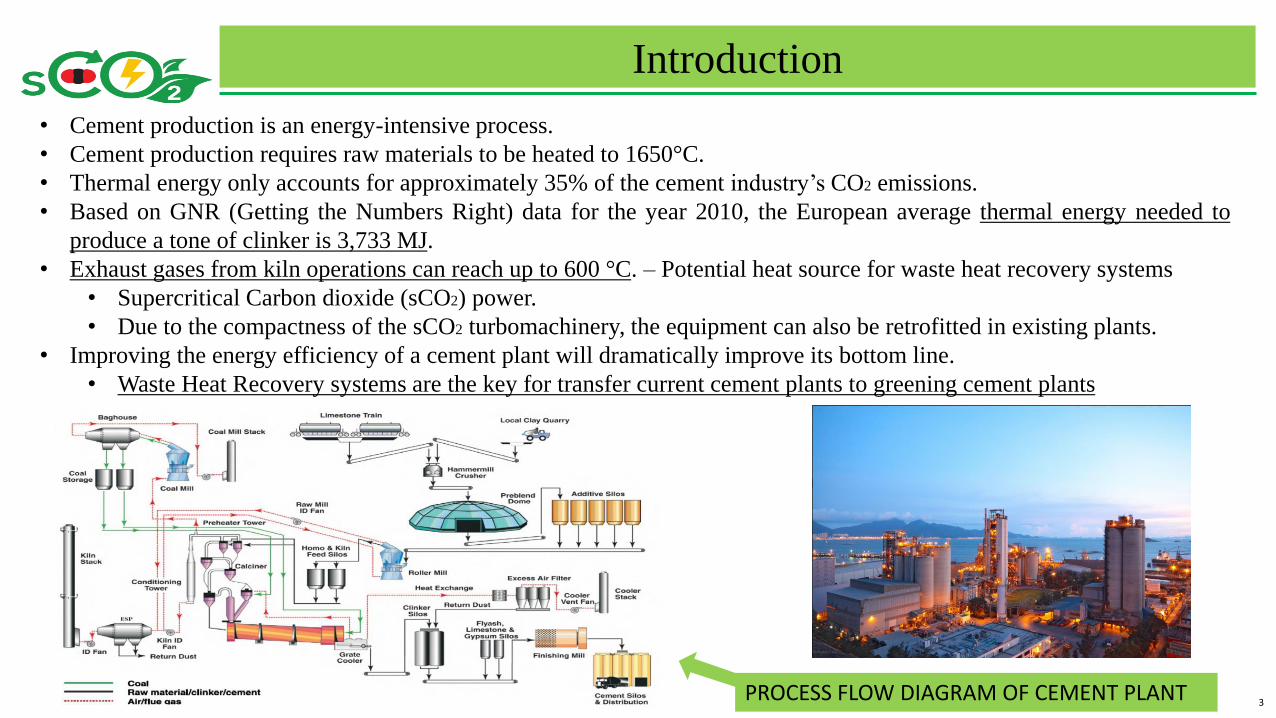
• Cement production is an energy-intensive process.
• Cement production requires raw materials to be heated to 1650°C.
• Thermal energy only accounts for approximately 35% of the cement industry’s CO2 emissions.
• Based on GNR (Getting the Numbers Right) data for the year 2010, the European average thermal energy needed to
produce a tone of clinker is 3,733 MJ.
• Exhaust gases from kiln operations can reach up to 600 °C. – Potential heat source for waste heat recovery systems
• Supercritical Carbon dioxide (sCO2) power.
• Due to the compactness of the sCO2 turbomachinery, the equipment can also be retrofitted in existing plants.
• Improving the energy efficiency of a cement plant will dramatically improve its bottom line.
• Waste Heat Recovery systems are the key for transfer current cement plants to greening cement plants
PROCESS FLOW DIAGRAM OF CEMENT PLANT
4
Sources of Waste Heat and Available Potential
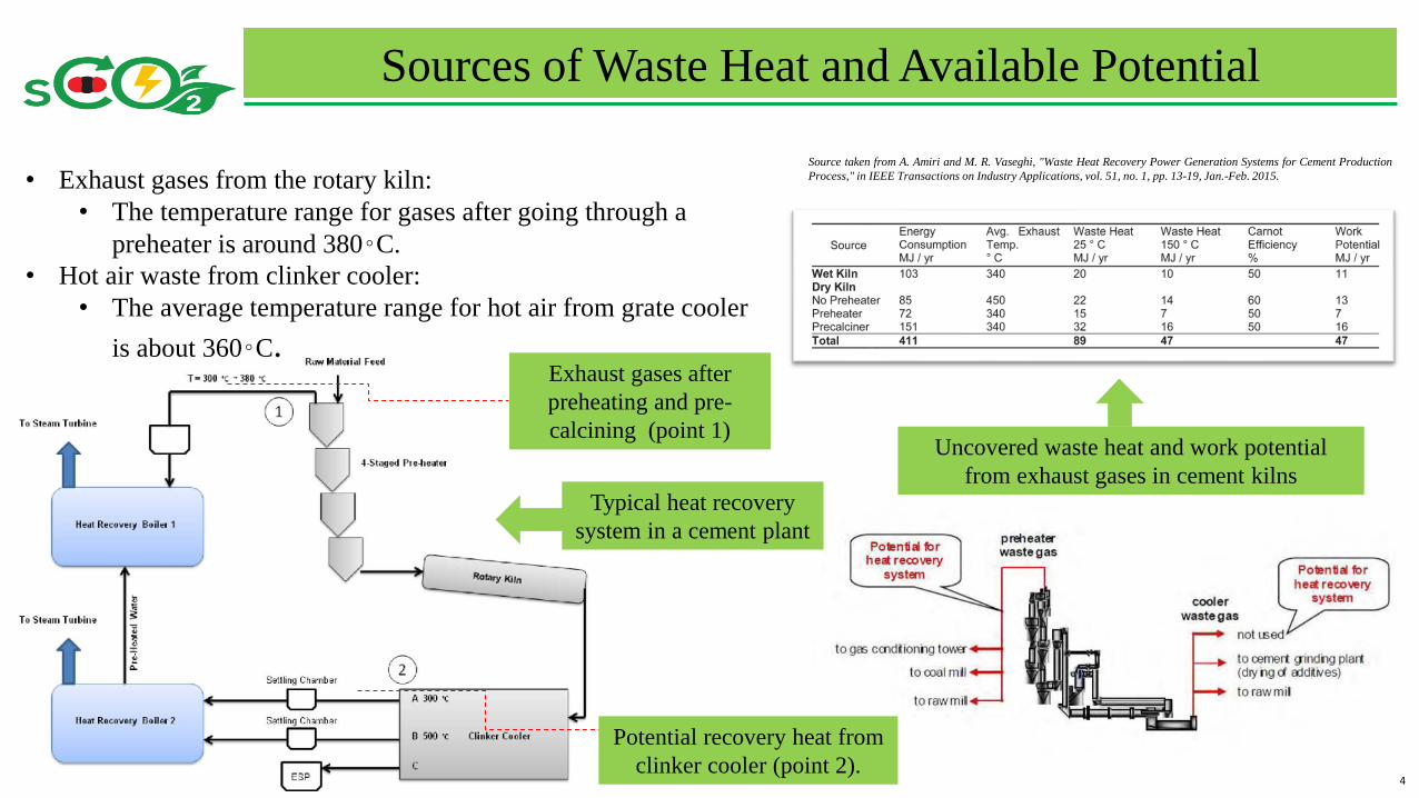
Source taken from A. Amiri and M. R. Vaseghi, "Waste Heat Recovery Power Generation Systems for Cement Production
Process," in IEEE Transactions on Industry Applications, vol. 51, no. 1, pp. 13-19, Jan.-Feb. 2015.• Exhaust gases from the rotary kiln:
• The temperature range for gases after going through a
preheater is around 380◦C.
• Hot air waste from clinker cooler:
• The average temperature range for hot air from grate cooler
is about 360◦C.
Uncovered waste heat and work potential
from exhaust gases in cement kilns
Exhaust gases after
preheating and pre-
calcining (point 1)
Potential recovery heat from
clinker cooler (point 2).
Typical heat recovery
system in a cement plant
5
Supercritical CO2 Power Generation Cycle Selection
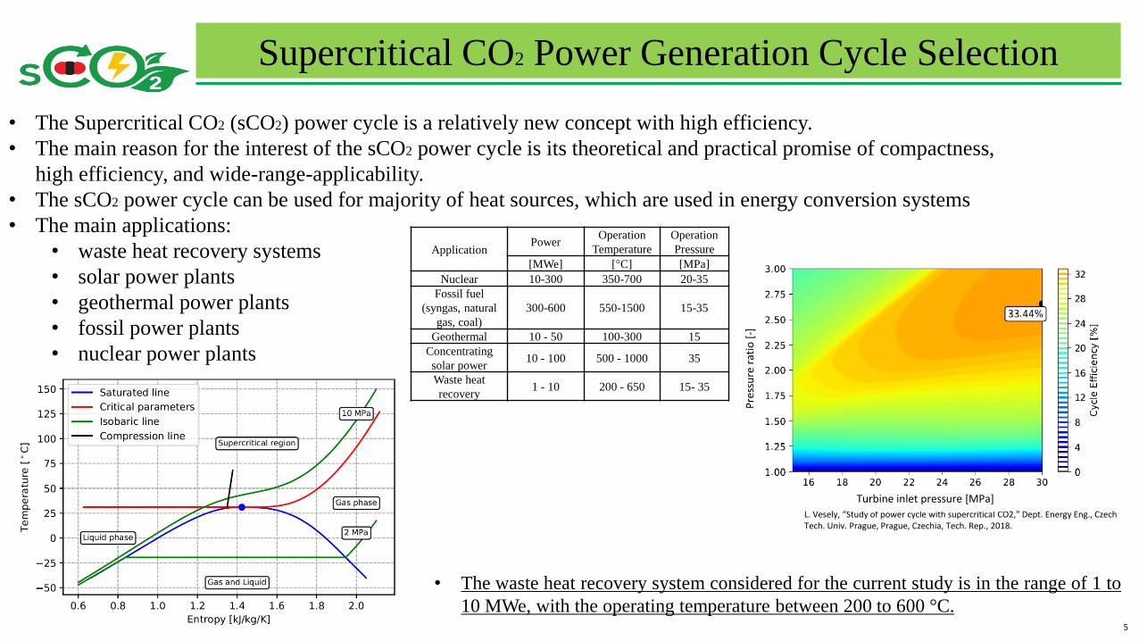
• The Supercritical CO2 (sCO2) power cycle is a relatively new concept with high efficiency.
• The main reason for the interest of the sCO2 power cycle is its theoretical and practical promise of compactness,
high efficiency, and wide-range-applicability.
• The sCO2 power cycle can be used for majority of heat sources, which are used in energy conversion systems
• The main applications:
• waste heat recovery systems
• solar power plants
• geothermal power plants
• fossil power plants
• nuclear power plants
ApplicationPower
Operation
Temperature
Operation
Pressure
[MWe] [°C] [MPa]
Nuclear 10-300 350-700 20-35
Fossil fuel
(syngas, natural
gas, coal)
300-600 550-1500 15-35
Geothermal 10 - 50 100-300 15
Concentrating
solar power10 - 100 500 - 1000 35
Waste heat
recovery1 - 10 200 - 650 15- 35
• The waste heat recovery system considered for the current study is in the range of 1 to
10 MWe, with the operating temperature between 200 to 600 °C.
L. Vesely, “Study of power cycle with supercritical CO2,” Dept. Energy Eng., Czech Tech. Univ. Prague, Prague, Czechia, Tech. Rep., 2018.
Pre
ssu
re r
atio
[-]
Turbine inlet pressure [MPa]
6
Scope and Novelty of the Work
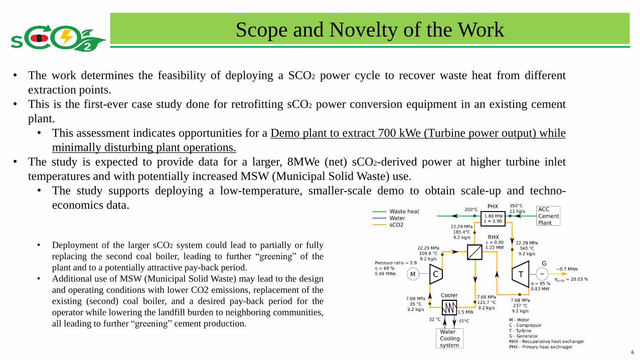
• The work determines the feasibility of deploying a SCO2 power cycle to recover waste heat from different
extraction points.
• This is the first-ever case study done for retrofitting sCO2 power conversion equipment in an existing cement
plant.
• This assessment indicates opportunities for a Demo plant to extract 700 kWe (Turbine power output) while
minimally disturbing plant operations.
• The study is expected to provide data for a larger, 8MWe (net) sCO2-derived power at higher turbine inlet
temperatures and with potentially increased MSW (Municipal Solid Waste) use.
• The study supports deploying a low-temperature, smaller-scale demo to obtain scale-up and techno-
economics data.
• Deployment of the larger sCO2 system could lead to partially or fully
replacing the second coal boiler, leading to further “greening” of the
plant and to a potentially attractive pay-back period.
• Additional use of MSW (Municipal Solid Waste) may lead to the design
and operating conditions with lower CO2 emissions, replacement of the
existing (second) coal boiler, and a desired pay-back period for the
operator while lowering the landfill burden to neighboring communities,
all leading to further “greening” cement production.
7
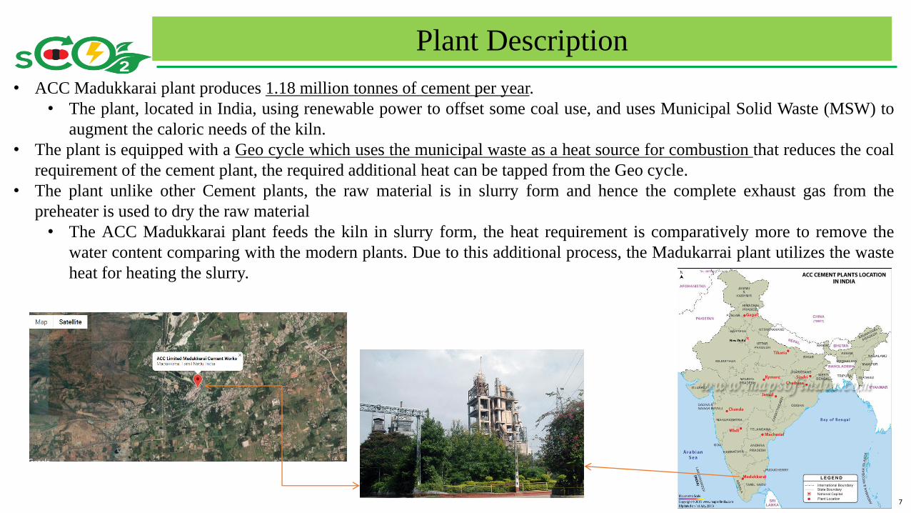
• ACC Madukkarai plant produces 1.18 million tonnes of cement per year.
• The plant, located in India, using renewable power to offset some coal use, and uses Municipal Solid Waste (MSW) to
augment the caloric needs of the kiln.
• The plant is equipped with a Geo cycle which uses the municipal waste as a heat source for combustion that reduces the coal
requirement of the cement plant, the required additional heat can be tapped from the Geo cycle.
• The plant unlike other Cement plants, the raw material is in slurry form and hence the complete exhaust gas from the
preheater is used to dry the raw material
• The ACC Madukkarai plant feeds the kiln in slurry form, the heat requirement is comparatively more to remove the
water content comparing with the modern plants. Due to this additional process, the Madukarrai plant utilizes the waste
heat for heating the slurry.
Plant Description
8
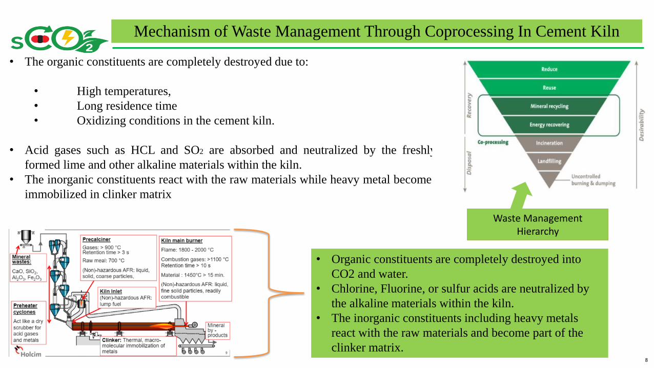
• The organic constituents are completely destroyed due to:
• High temperatures,
• Long residence time
• Oxidizing conditions in the cement kiln.
• Acid gases such as HCL and SO2 are absorbed and neutralized by the freshly
formed lime and other alkaline materials within the kiln.
• The inorganic constituents react with the raw materials while heavy metal becomes
immobilized in clinker matrix
Waste Management Hierarchy
• Organic constituents are completely destroyed into
CO2 and water.
• Chlorine, Fluorine, or sulfur acids are neutralized by
the alkaline materials within the kiln.
• The inorganic constituents including heavy metals
react with the raw materials and become part of the
clinker matrix.
Mechanism of Waste Management Through Coprocessing In Cement Kiln
9
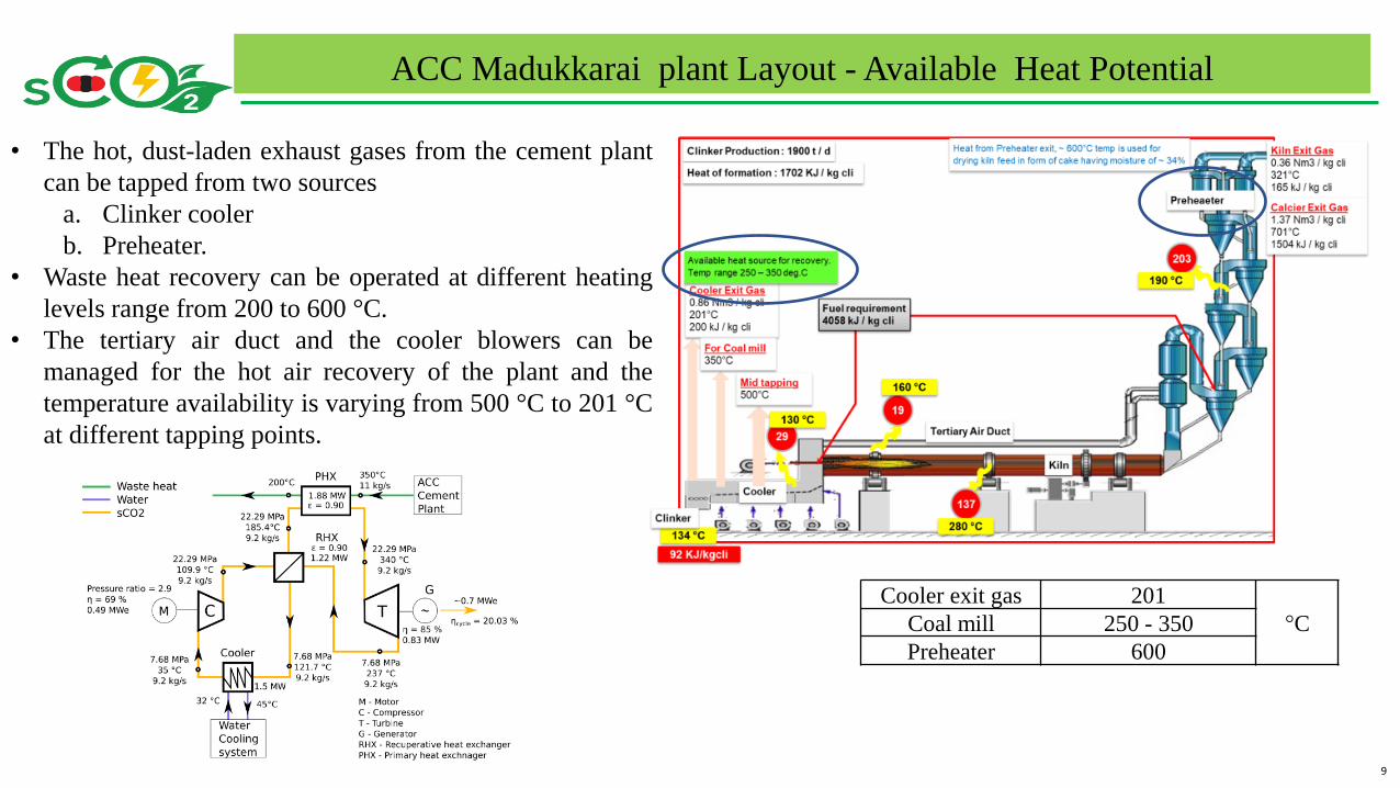
• The hot, dust-laden exhaust gases from the cement plant
can be tapped from two sources
a. Clinker cooler
b. Preheater.
• Waste heat recovery can be operated at different heating
levels range from 200 to 600 °C.
• The tertiary air duct and the cooler blowers can be
managed for the hot air recovery of the plant and the
temperature availability is varying from 500 °C to 201 °C
at different tapping points.
ACC Madukkarai plant Layout - Available Heat Potential
Cooler exit gas 201
°CCoal mill 250 - 350
Preheater 600
10
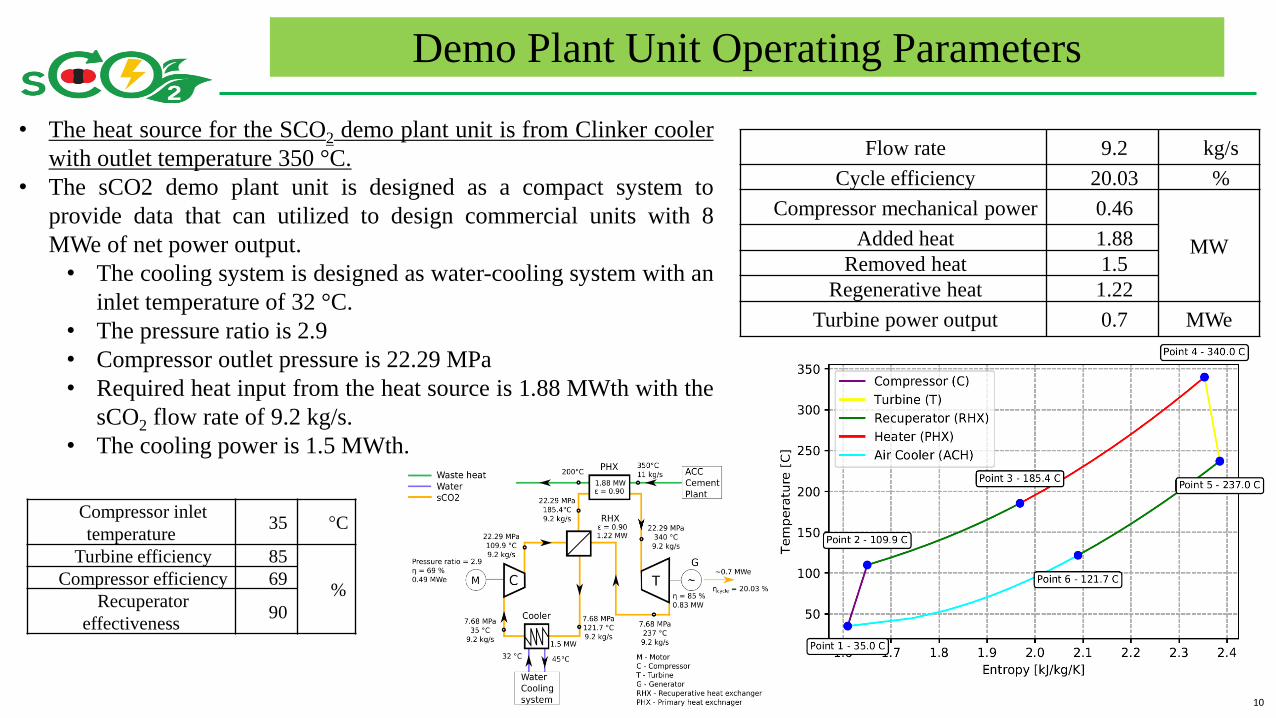
Compressor inlet
temperature35 °C
Turbine efficiency 85
%Compressor efficiency 69
Recuperator
effectiveness90
Demo Plant Unit Operating Parameters
• The heat source for the SCO2 demo plant unit is from Clinker cooler
with outlet temperature 350 °C.
• The sCO2 demo plant unit is designed as a compact system to
provide data that can utilized to design commercial units with 8
MWe of net power output.
• The cooling system is designed as water-cooling system with an
inlet temperature of 32 °C.
• The pressure ratio is 2.9
• Compressor outlet pressure is 22.29 MPa
• Required heat input from the heat source is 1.88 MWth with the
sCO2 flow rate of 9.2 kg/s.
• The cooling power is 1.5 MWth.
Flow rate 9.2 kg/s
Cycle efficiency 20.03 %
Compressor mechanical power 0.46
MWAdded heat 1.88
Removed heat 1.5
Regenerative heat 1.22
Turbine power output 0.7 MWe
11
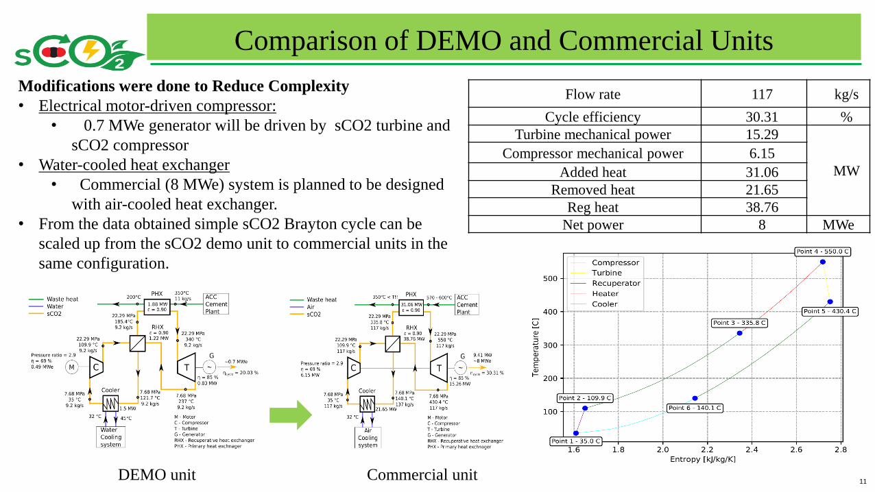
Comparison of DEMO and Commercial Units
Modifications were done to Reduce Complexity
• Electrical motor-driven compressor:
• 0.7 MWe generator will be driven by sCO2 turbine and
sCO2 compressor
• Water-cooled heat exchanger
• Commercial (8 MWe) system is planned to be designed
with air-cooled heat exchanger.
• From the data obtained simple sCO2 Brayton cycle can be
scaled up from the sCO2 demo unit to commercial units in the
same configuration.
Flow rate 117 kg/s
Cycle efficiency 30.31 %
Turbine mechanical power 15.29
MW
Compressor mechanical power 6.15
Added heat 31.06
Removed heat 21.65
Reg heat 38.76
Net power 8 MWe
DEMO unit Commercial unit
12
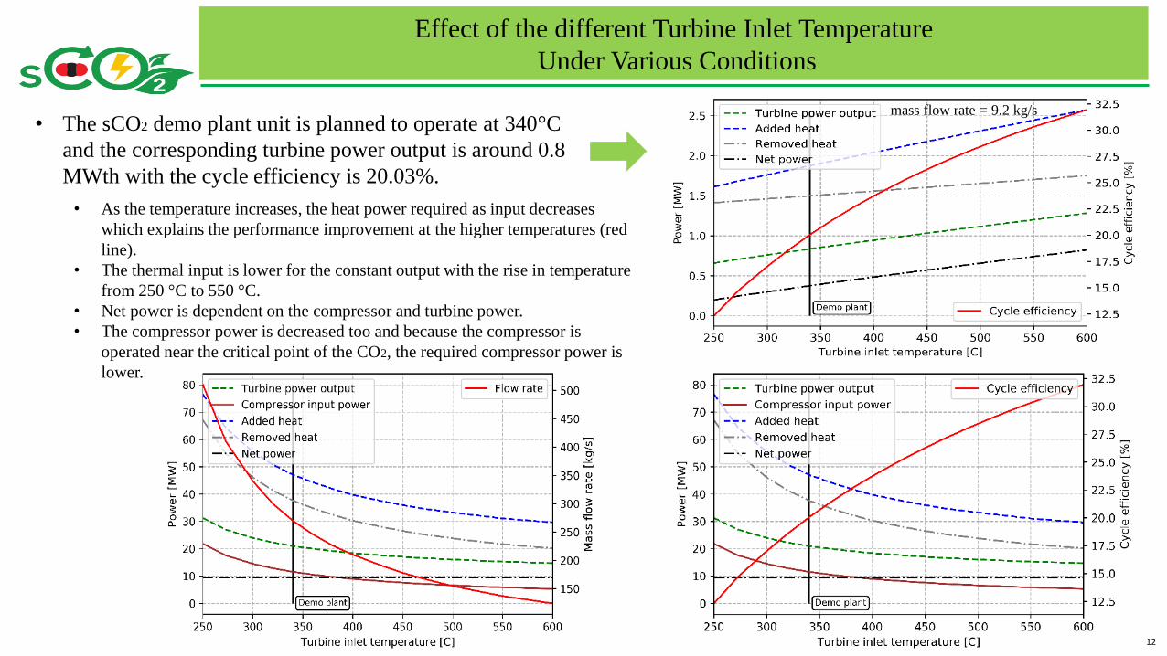
Effect of the different Turbine Inlet Temperature
Under Various Conditions
• The sCO2 demo plant unit is planned to operate at 340°C
and the corresponding turbine power output is around 0.8
MWth with the cycle efficiency is 20.03%.
• As the temperature increases, the heat power required as input decreases
which explains the performance improvement at the higher temperatures (red
line).
• The thermal input is lower for the constant output with the rise in temperature
from 250 °C to 550 °C.
• Net power is dependent on the compressor and turbine power.
• The compressor power is decreased too and because the compressor is
operated near the critical point of the CO2, the required compressor power is
lower.
mass flow rate = 9.2 kg/s
13
• The cycle optimization could lead to a maximum overallwaste-heat-to-electricity efficiency of 30.3% for a net poweroutput of 8 MWe and a turbine inlet temperature of 550 °C.
• Simple Brayton sCO2 power cycle
• The cement plant heat source can be used for many differentcycle layouts and with a combination of Hydrogen systemscan lead to the high-efficiency green cement plant.
Conclusions & Recommendations
• This study focused on retrofitting of an existing cement plant in order to make it green.
• Consideration of all other sources of waste heat, as well as use of locally-sourced municipal solid waste, can increase
the exergy-content of the total waste heat at a higher temperature and can lead to larger net electrical output at a
higher overall cycle efficiency.
• For a completely new design, an overall design optimization that considers both cement production and waste heat
recovery in an integrated fashion is necessary

14
Conclusions & Recommendations
Thank you for your attention