grc telescience support center implementation plan · web viewthe separation is required to...
TRANSCRIPT

TSC-DOC-004D
GRC Telescience Support Center Implementation Plan
Microgravity Science Division
Rev. DJune 12, 2003
AUTHORIZED by CM when under FORMAL Configuration Control
Date Signature10/03/03 /s/ Robert H. Van Niel
Availability:
[ ] Public (No Restriction) [ X ] Export Controlled;Classification = EAR-9A004
National Aeronautics and Space AdministrationJohn H. Glenn Research CenterMicrogravity Science DivisionCleveland, Ohio 44135
TSC-DOC-004DJune 12, 2003
PREFACE
Under the Microgravity Research, Development, and Operations Contract (MRDOC), the National Aeronautics and Space Administration (NASA) is developing a modular, multi-user experimentation facility for conducting fluid physics and combustion science experiments in the microgravity environment of the International Space Station (ISS). This facility, called the Fluids and Combustion Facility (FCF), consists of two test platforms: the Fluids Integrated Rack (FIR), and the Combustion Integrated Rack (CIR). Also included in MRDOC are the required support efforts for Mission Integration and Operations, consisting of the Telescience Support Center (TSC) and Mission Integration and Planning (MIP).
The Telescience Support Center (TSC) Facility provides the required support efforts for the MRDOC.
This document establishes the implementation guidelines for the TSC supporting payload activity for the International Space Station Program.
iii GRC TSC Implementation Plan

TSC-DOC-004DJune 12, 2003
SIGNATURE PAGE
GRC TELESCIENCE SUPPORT CENTERIMPLEMENTATION PLAN
FOR THEMICROGRAVITY SCIENCE DIVISION
Prepared By: /s/ C. Sommer Date: 07/02/03 Charles E. SommerTSC Operations LeadJackson and Tull
Approved By: /s/ Thomas J. Wasserbauer Date: 07/08/03 Thomas J. WasserbauerTSC Project ManagerNorthrop Grumman Information Technology
Approved By: /s/ Michael R. Johanson Date: 07 /08/03 Michael R. JohansonIncrement 12 ManagerNorthrop Grumman Information Technology
iv GRC TSC Implementation Plan
TSC-DOC-004DJune 12, 2003
SIGNATURE PAGE (CONTINUED)
GRC TELESCIENCE SUPPORT CENTERIMPLEMENTATION PLAN
FOR THEMICROGRAVITY SCIENCE DIVISION
Approved By: /s/ Diane C. Malarik Date: 09 /30/03 Diane C. MalarikTelescience Operations ManagerMicrogravity Science DivisionNASA Task Manager, Contract #NAS3-99155, Exhibit 2, DO52NASA Glenn Research Center
v GRC TSC Implementation Plan
TSC-DOC-004DJune 12, 2003
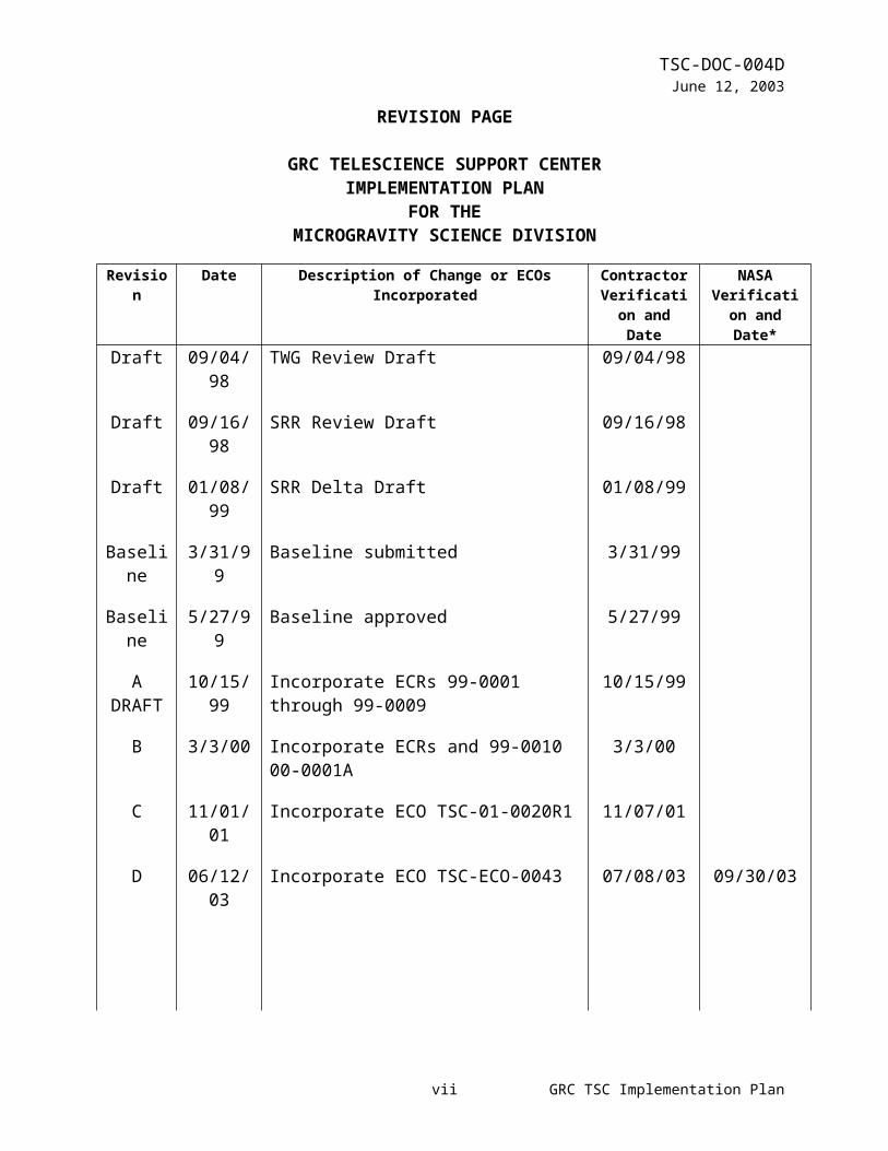
REVISION PAGE
GRC TELESCIENCE SUPPORT CENTERIMPLEMENTATION PLAN
FOR THEMICROGRAVITY SCIENCE DIVISION
Revision Date Description of Change or ECOs Incorporated
Contractor Verification
and Date
NASA Verification and Date*
Draft 09/04/98 TWG Review Draft 09/04/98
Draft 09/16/98 SRR Review Draft 09/16/98
Draft 01/08/99 SRR Delta Draft 01/08/99
Baseline 3/31/99 Baseline submitted 3/31/99
Baseline 5/27/99 Baseline approved 5/27/99
A DRAFT
10/15/99 Incorporate ECRs 99-0001 through 99-0009 10/15/99
B 3/3/00 Incorporate ECRs and 99-0010 00-0001A 3/3/00
C 11/01/01 Incorporate ECO TSC-01-0020R1 11/07/01
D 06/12/03 Incorporate ECO TSC-ECO-0043 07/08/03 09/30/03
*Enter “N/A” if NASA approval is not required by contract.
vi GRC TSC Implementation Plan
TSC-DOC-004DJune 12, 2003
TABLE OF CONTENTS
1.0 INTRODUCTION.............................................................................11.1 Scope...............................................................................................11.2 Purpose............................................................................................11.3 Applicability......................................................................................1
2.0 DOCUMENTS..................................................................................22.1 Reference Documents.....................................................................22.2 Applicable Documents.....................................................................2
3.0 DOCUMENT ORGANIZATION........................................................3
4.0 IMPLEMENTATION APPROACH...................................................44.1 Overall TSC.....................................................................................44.1.1 Overall TSC Capacity......................................................................44.1.2 Overall TSC Restorability.................................................................44.1.3 Systems and Services Description..................................................54.1.4 Performance Assessment Process..................................................64.1.5 Sustaining Engineering....................................................................64.2 Audio System...................................................................................74.2.1 Audio System Capacity....................................................................84.2.2 Audio System Availability/Restorability............................................84.3 Video System...................................................................................84.3.1 Video System Capacity..................................................................104.3.2 Video System Availability/Restorability..........................................104.3.3 Video Recording............................................................................104.4 Telecommunications system..........................................................114.4.1 Telecommunications Systems Capacity........................................124.4.2 Telecommunications Systems Availability/Restorability................124.5 Conferencing System.....................................................................134.5.1 Conferencing System Capacity......................................................134.5.2 Conferencing System Availability/Restorability..............................134.5.3 Remote Users Conferencing Systems...........................................134.6 Data System..................................................................................144.6.1 Data System Workstations.............................................................174.6.1.1 Data System Capacity...................................................................174.6.1.2 Data System Availability/Restorability............................................174.6.2 Telemetry.......................................................................................184.6.2.1 Telemetry Capacity........................................................................194.6.3 Commanding..................................................................................194.6.3.1 Commanding Capacity...................................................................194.6.4 Mission Services............................................................................194.6.5 Storage of Telemetry Data.............................................................194.6.5.1 Mass Storage Data Capacity.........................................................204.7 Networking System........................................................................20
vii GRC TSC Implementation Plan

TSC-DOC-004DJune 12, 2003
4.7.1 Network System Capacity..............................................................224.7.2 Network System Availability/Restorability......................................224.7.3 Network Isolation...........................................................................224.8 Timing System...............................................................................224.8.1 Timing System Capacity................................................................234.8.2 Timing System Availability/Restorability........................................234.9 Ground Track System....................................................................244.9.1 Ground Track System Capacity.....................................................254.9.2 Ground Track System Availability/Restorability.............................254.10 Facility............................................................................................254.10.1 Facility Overview............................................................................254.10.2 Facility Capacity.............................................................................274.10.3 Facility User Accommodations.......................................................274.10.4 Maintenance..................................................................................274.11 Operations.....................................................................................284.11.1 TSC Operations Approach.............................................................284.11.2 TSC Pre-increment Operations Activities......................................294.11.3 TSC Increment Operations Activities.............................................304.11.4 TSC Post-increment Operations Activities.....................................304.12 Security Assessment Process.......................................................314.13 Training and Certification...............................................................324.13.1 Training Process............................................................................324.13.2 Certification Plan............................................................................32
5.0 ACRONYM LISTING.....................................................................33
6.0 GLOSSARY...................................................................................34
APPENDIX A TO BE DETERMINED (TBD) ITEMS.............................................36
APPENDIX B TRD to TIP Requirement Cross Reference Matrix..................................37
viii GRC TSC Implementation Plan

TSC-DOC-004DJune 12, 2003
TABLE OF FIGURES
Figure 4.1.3 TSC Systems Overview...............................................................................6
Figure 4.2 TSC Audio System..........................................................................................7
Figure 4.3 TSC Video System..........................................................................................9
Figure 4.4 TSC Telecommunications System................................................................11
Figure 4.5 TSC Conferencing System...........................................................................13
Figure 4.6-1 TSC Data System......................................................................................15
Figure 4.6-2 TSC Mass Storage System.......................................................................16
Figure 4.7 TSC Networking System...............................................................................21
Figure 4.8 TSC Timing System......................................................................................23
Figure 4.9 TSC Ground Track System...........................................................................24
Figure 4.10 TSC Facility Overview................................................................................26
Figure 4.11 TSC Operations..........................................................................................28
Figure 4.12 TSC Security Risk Management.................................................................31
ix GRC TSC Implementation Plan

TSC-DOC-004DJune 12, 2003A
1.0INTRODUCTIONThe Telescience Support Center (TSC) Implementation Plan (TIP) establishes the implementation guidelines for TSC Phase 1 support during ISS Increments 2 through 6. This document will meet all of the TSC Phase 1 requirements listed in the TSC Requirements Document (TRD). Section 7 of this document contains the requirement cross-reference matrix between the TRD and the TIP.
1.1ScopeThis document establishes the Telescience Implementation Plan for the NASA Glenn Research Center (GRC) Telescience Support Center (TSC). This document will be identified as TSC-DOC-004 and referred to as the TIP. The TIP is under the control of the GRC Microgravity Science Division (MSD) and subordinate to the TRD. A future release of this document will be provided to cover TSC Phase 2 (ISS Increment 7 and later) implementation guidelines.
1.2PurposeThe purpose of the TIP is to define an implementation for the International Space Station (ISS) telescience requirements, which support GRC TSC local and remote ISS ground operations.
1.3ApplicabilityThe TIP is applicable to the Phase 1 TSC implementation for payloads manifested on the ISS during Increments 2 through 6.
1 GRC TSC Implementation Plan
TSC-DOC-004DJune 12, 2003A
2.0DOCUMENTS
2.1Reference Documents
Reference documents are those documents that, although not part of this document, serve to amplify or clarify its contents, or dictate work policy or procedures. The specific reference documents are as follows:
TSC Operation Concept Document TSC-DOC-003 TSC Security Plan TSC-DOC-014 TSC Configuration Management Plan TSC-DOC-007 TSC Training and Certification Plan TSC-DOC-015 TSC Integration, Verification and Test Plan TSC-DOC-017TSC Users Guide TSC-DOC-006 POIC Capabilities Document SSP-50304 POIC Generic User Interface Definition Document SSP-50305 JSC Program Requirements for Payload Developers SSP-50431 MSFC HOSC Telemetry Format Standard MFSC-STD-1274 MSFC HOSC Database Definitions MFSC-DOC-1949
2.2Applicable DocumentsApplicable documents are those documents, of the latest revision, whose content, to the extent specified herein, are considered to form a part of this document. The specified parts of the applicable documents carry the same weight as if they were stated within the body of this document. The applicable documents are as follows:
TSC Project Plan TSC-DOC-001 TSC Requirements Document TSC-DOC-002 HOSC to GRC TSC ICD SSP-50366 Program Requirements for Payload Developers SSP-50431 Payload Data Sets Blank Book SSP-52000-PDS Payload Ground Support Personnel Training and Certification Plan MSFC-PLAN-2848 NASA Management Instruction: NASA Security Program NMI 1600.2
2 GRC TSC Implementation Plan

TSC-DOC-004DJune 12, 2003A
3.0DOCUMENT ORGANIZATIONThe TIP Document comprises seven sections. The organization of the document with respect to each section is described here.
Section #1- Introduction defines the document scope, purpose, and applicability.
Section #2- Documents lists reference and applicable documents, as they pertain to the TIP.
Section #3- Document Organization describes how the TIP is organized.
Section #4- Implementation Approach describes how TRD requirements will be implemented. This section is broken down into 12 subsections. Each subsection defines the implementation for one major TSC system (eight systems total) or service (four services total).
Section #5- Acronym Listing provides a list of acronyms used in this document.
Section #6 Glossary provides a list of terms used in this document.
Section #7 Appendix A contains TBD items.
Section #8 Appendix B contains a TIP to TRD requirement cross-reference matrix.
3 GRC TSC Implementation Plan

TSC-DOC-004DJune 12, 2003A
4.0IMPLEMENTATION APPROACHDuring implementation, the TSC will adhere to the following:
a) Commercial Off The Shelf (COTS) products will be used to the maximum extent.
b) All internal interfaces will be documented and controlled per the GRC TSC Configuration Management Plan. External interfaces described in the HOSC to GRC TSC ICD will be controlled by the GSCB at JSC. This document describes the external interfaces between the POIC and the GRC TSC. All other external interfaces will be described in the GRC TSC Configuration Management Plan.
c) All documentation will be written and controlled per the established TSC Project Plan, TSC Configuration Management Plan, and ISO 9001 guidelines.
d) All TSC computer hardware and software will conform to Year 2000 performance guidelines.
4.1Overall TSCThe TSC will be phased to support ISS Increment 2 through 6 (TSC Phase 1) operations within Building 333 at the NASA GRC and from location's offline and remote to the TSC. ISS operations support will include real-time operations, simulated operations, and onsite ground support personnela training.
4.1.1 Overall TSC CapacityPhase 1 of the TSC will be designed to provide the following services simultaneously to users:
a) Two full-scale operations (real-time and/or simulated) for 30 usersb) Five users at 2 off-line operations areas
4.1.2 Overall TSC RestorabilityTSC systems and services are classified as either operations-critical or operations-noncritical for purposes of restorability. The definitions of operations-critical and operations-noncritical are as follows:
Operations-critical systems and services are those that, when lost, will significantly impact multiple/all experiments or cause catastrophic loss of data to one experiment. All TSC systems, elements, or services used in real-time operations within the TSC are classified as operations-critical. All TSC-provided systems, elements, or services at remote sites are operations-critical, only if the operations capability exists exclusively at that site.
Operations-noncritical systems and services are those that, when lost, will not significantly impact multiple experiments or cause catastrophic loss of data to one experiment. This also applies to most simulation and training support services. All TSC systems, elements, or services used exclusively in training or simulations are classified as operations-noncritical. TSC systems,
4 GRC TSC Implementation Plan
TSC-DOC-004DJune 12, 2003A
elements, or services whose functions are duplicated in other systems or services, excluding system redundancies, are classified as operations-noncritical. TSC systems, elements, or services used exclusively at off-line operations areas or remote sites are classified as operations-noncritical, except when the remote site has exclusive operations capability.
The Maximum Time to Restore Service (MaxTTR) for operations-critical TSC services will be 4 hours during day shift, and 8 hours during other shifts. The MaxTTR for operations-noncritical services (or systems in operations-noncritical usage) will be 8 hours during day shift, and a next day shift for failures during other shifts. These MaxTTR numbers will be achieved through the following approach:
a. On-site whole unit replacements and card level sparesb. A trained technical staff to perform failure analysis, fault isolation, equipment replacement,
and problem tracking and resolutionc. Lab service and vendor maintenance contracts to provide on-call service
4.1.3 Systems and Services DescriptionThe TSC can be broken down into eight major systems and four major services. The eight major systems include Audio, Video, Telecommunications, Videoconferencing, Data, Networking, Timing, and Ground Track Systems. The Audio System provides access to ISS voice loops and TSC-generated audio. The Video System provides access and displays of ISS downlink video and TSC-generated video. The Telecommunications System provides the link between the GRC telecommunications Point of Presence (POP) and the other TSC systems. The Videoconferencing System provides bi-directional audio and video communications with other NASA centers and remote sites. The Data System provides telemetry, commanding, ISS mission services access, and administrative services capabilities. The Networking System provides connections among the Data System, the Telecommunications System, and GRC lab networks (Internet). The Timing System provides displays of ISS real and simulated times. The Ground Track System provides displays of ISS on-orbit and predicted TDRS AOS/LOS times. Figure 4.1 TSC Systems Overview shows the relationships among these systems. The four major services include Facility, Operations Support, Security, and Training and Certification services. These major systems and services provide support for ISS simulations and on-orbit operations. Redundancy is incorporated into every critical system.
5 GRC TSC Implementation Plan

TSC-DOC-004DJune 12, 2003A
Figure 4.1.3 TSC Systems Overview
4.1.4 Performance Assessment ProcessThe TSC system/equipment/software performance will be verified through methods of testing and simulations. When equipment/software is received, this process will begin with acceptance testing, and end with increment testing. The level of intermediate testing required will be system/equipment dependent. The TSC Integration, Verification and Test Plan, TSC-DOC-017, defines acceptance criteria, which will be used during the testing process. Each piece of equipment or software may require a different level of testing depending on the methods that must be used to prove the acceptance criteria have been met. Each TSC system will be reviewed during the Operations Readiness Review process to ensure all system equipment and software is ready to support on-orbit operations.
4.1.5 Sustaining EngineeringThe overall TSC life expectancy is designed for 15 years, with equipment replacement every four to six years. To this end, the TSC will employ a method of sustained engineering through continuous process review and planned equipment turnover. Continuous process review involves modification and upgrade of existing systems to meet TSC user needs on an incremental basis. Planned equipment turnover allows for the periodic replacement of hardware in accordance with estimated maintenance requirements and age limitations. It also allows the TSC to integrate newer technologies required for user support.
6 GRC TSC Implementation Plan
TSC-DOC-004DJune 12, 2003A
4.2Audio SystemThe TSC has voice communications services available to its users during training, testing, simulation and mission operations. Voice communications are available between GRC, MSFC, and JSC through the ISS voice loop service provider. Figure 4.2 shows a block diagram of the TSC Audio System.
Figure 4.2 TSC Audio System
7 GRC TSC Implementation Plan
TSC-DOC-004DJune 12, 2003A
The TSC Audio System will perform the following functions:
a) Receive and transmit signals from and to the ISS voice loop service provider.b) Distribute individual voice loops to the Operator Communications Panel.c) Provide access to Channel Banks for TSC generated and external audio sources.d) Provide an analog bridge and amplifiers to distribute voice grade circuits from more than one
sourceA System Administration Terminal (SAT) will be used to configure and distribute voice loops, diagnostics, and security.
4.2.1 Audio System CapacityThe TSC audio system will accept voice loops for multiple operations, and then configure the system to distribute the correct voice loops to each audio station. The capability to interface with 72 loops (or other audio sources) will be provided by the DICES III element. Up to 40 audio stations will be provided within the TSC.
Each audio station will be capable of selecting combinations of up to 30 pre-set loops by switches on the front panel of the audio station. Each station is intended to support 2 users, and provides two headset connections and independent audio controls. The DICES III system element will configure the correct loops at each audio station, and provide the allowed permissions (talk/listen versus monitor only). The talk/listen capability versus monitor capability will be selected for each loop by the user within the permissions configured at that audio station.
4.2.2 Audio System Availability/RestorabilityTo meet the availability and restorability criteria specified in the TSC Requirements Document; the DICES III element will use redundant CPUs, internal busses, and power supplies. To meet the overall audio system restorability requirements, all modules and power supplies will be “hot” swappable, and most cards and modules will be spared locally. Restorability for end user equipment will be met by having space items (headsets and audio stations) spared locally, and by having 24x7 TSC technician support when users are in the facility.
4.3Video SystemThe TSC will provide users that require ISS real-time video as part of the operation requirements, a connection to the ISS video source through video distribution amplifiers that bypass the video matrix. This will increase reliability of the ISS real-time video to the users that need it most.
The TSC will provide all other users access to the matrix video switching system. This will give the individual users at audio-video stations the ability to independently select the desired video for monitoring and recording. The user at the TSC will be able to select 1 video channel.
8 GRC TSC Implementation Plan
TSC-DOC-004DJune 12, 2003A
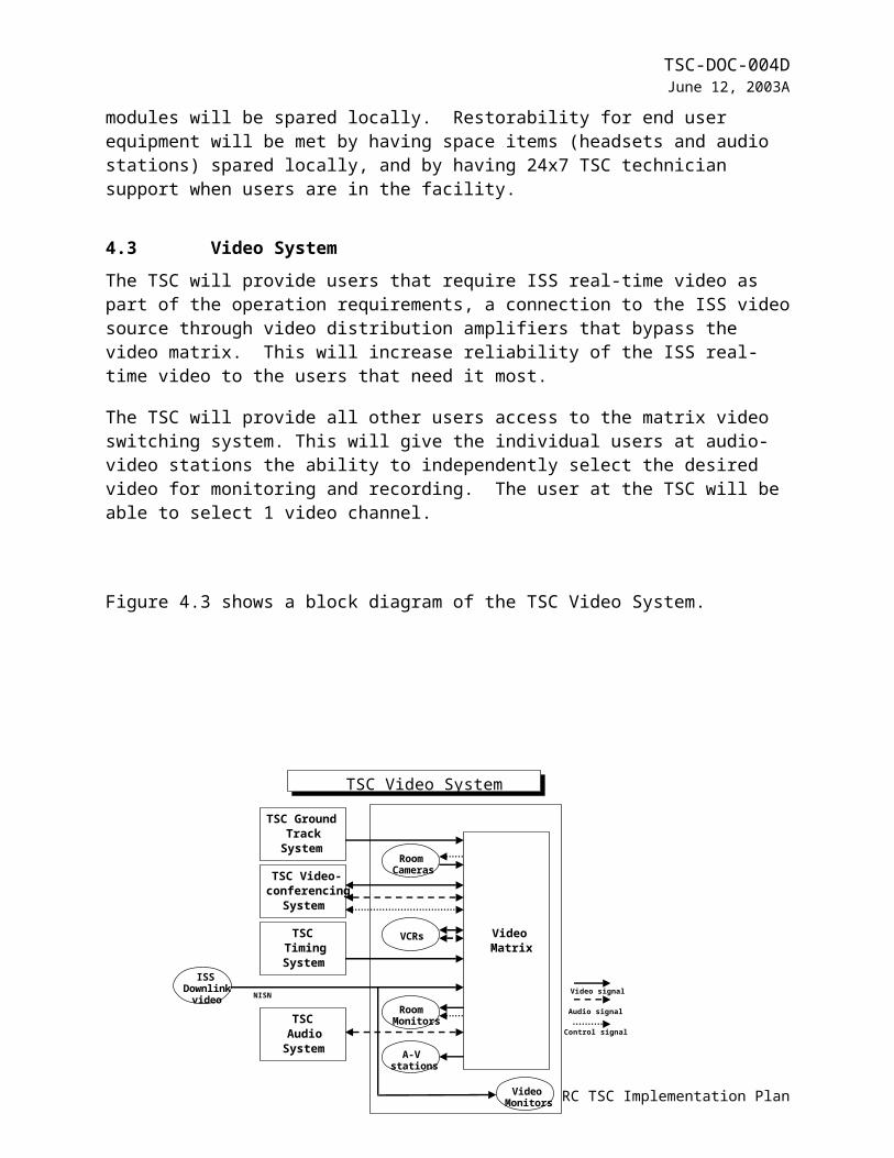
Figure 4.3 shows a block diagram of the TSC Video System.
Figure 4.3 TSC Video System
The Phase 1 Video System will handle NTSC RS-170 composite video and S-video. For most users, this capability will be supplied through the TSC video matrix. Two channels of real-time ISS video provided to the user. Users will be provided with views of ground track and timing displays. Users will be provided with views of the rooms that comprise the TSC facility, hallways that connect those rooms, and the Building 333 high bay. Users will have access to NASA TV, a TSC selectable local GRC Link video channel, and a VCR to be used for playback of pre-recorded video. One video station, with one 13-inch color video monitor, will be provided for each audio station (40 stations total). Video feeds for up to four total user-provided pieces of video equipment will also be provided. User access will be restricted to approved video sources and destinations.
For users that have ISS real-time video as a critical part of their operations, this video will be routed through video distribution amplifiers to separate monitors in their operation areas.
9 GRC TSC Implementation Plan
TSCTimingSystem
VideoMatrix
TSC GroundTrack
System
TSC Video-conferencing
System
TSCAudio
System
RoomCameras
VCRs
RoomMonitors
A-Vstations
Video signal
Audio signal
Control signal
ISSDownlink
video NISN
VideoMonitors
TSC Video System

TSC-DOC-004DJune 12, 2003A
4.3.1 Video System CapacityA scalable matrix router capable of providing composite video will be implemented to meet the requirements for quantity of inputs and outputs specified in the TSC Requirements Document. The matrix will have 56 inputs and 56 outputs. Two inputs will be dedicated to real time ISS downlink video. The matrix will provide 25 video stations with 1 selectable channel each and 31 other destinations, such as large monitors and projectors, TSC rack-mounted monitors, and video recorders. The video matrix router will interface to satellite receivers, analog decoders, TSC video recording equipment, TSC video cameras, TSC videoconferencing equipment, console monitors and various scan converted computer displays. The video matrix router will also have an audio matrix portion. The audio portion will interface with the audio communications system and other audio based equipment within the TSC. This will provide users extra flexibility in transmission and reception of audio/video signals to the recorders and conferencing equipment.
4.3.2 Video System Availability/RestorabilityTo meet the availability/restorability requirement specified in the TSC Requirements Document, real-time downlink ISS video will bypass the video matrix and be routed through video distribution amplifiers to users that require that video as a critical part of their operations. This part of the TSC video system will have an availability of 0.95 or better, and a MaxTTR the same or better than the overall TSC requirement for operations-critical services. Other parts of the TSC video system will have a MaxTTR the same or better than the overall TSC requirement for operations-noncritical services.
The video matrix router will have replacement cards, boards, and power supplies on site. System control for video switching will be provided at each console. An AMX controller with an Autopatch switcher will be used. The user interface will be provided on a separate server which will interface with the AMX controller. The TSC operations staff will set up access lists for each console to limit the switching capabilities to only the necessary functions for each unique user. The TSC operations staff will also maintain total control of the system using a COTS GUI.
End user equipment, such as monitors, will have a MaxTTR of 1 hour during day shift and a next day shift if failure occurs during other shifts. Monitors will be spared on site.
4.3.3 Video RecordingThe matrix system will supply video and audio to video recorders to allow simultaneous and continuous recording of two video channels.
10 GRC TSC Implementation Plan
TSC-DOC-004DJune 12, 2003A
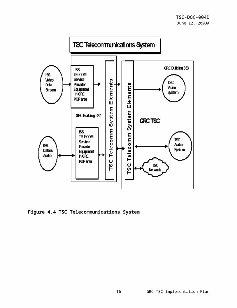
4.4Telecommunications system.The Telecommunications System will transport the signals from MSFC/JSC at the ISS telecomm service provider’s Point of Presence (POP) at GRC to the TSC, where the individual signals can be distributed to the TSC Audio, Video, and Networking Systems.
The TSC will provide fiber optic transceivers for extension of the data WAN, a multiplexer-demultiplexer to carry voice circuits over fiber, and Video Transmission Systems to carry video NSTC signals over fiber. Figure 4.4 shows a block diagram of the TSC Telecommunications System.
Figure 4.4 TSC Telecommunications System
11 GRC TSC Implementation Plan

TSC-DOC-004DJune 12, 2003A
4.4.1 Telecommunications Systems CapacityThe engineering concept is to provide 3 separate transport mechanisms; one for each service.
- For data, a 100 Mbps fiber Ethernet extension will be used from the ISS telecommunication service provider’s equipment and the GRC lab maintained firewall to the TSC operations network equipment. Fiber 100 Mpbs Ethernet connections will be used at the TSC operations networking equipment, the GRC maintained firewall, and the ISS telecommunication service provider’s equipment.
- The T-1 circuits for the audio loops will be multiplexed together, transmitted over a fiber to the TSC, demultiplexed, and fed directly into the Central Audio processor and Interface Element.
- Video NTSC will be extended from the ISS service provider demarcation point by a TSC provided Video Transmission System over GRC lab maintained fiber and feed into the TSC video system.
The Telecommunications System will provide communication format and protocols required in the TSC Requirements Document through at least one of the above mechanisms.
4.4.2 Telecommunications Systems Availability/RestorabilityTo meet the availability and restorability requirements specified in the TSC Requirements Document, the Telecommunication System will be developed with the following:
- The audio T-1 transport will have redundant multiplex/demultiplex cards providing dual-homed redundant fiber optic connections and be equipped with a microprocessor for provisioning and network monitoring from a single location. This transport will provide internal AC to DC power conversion with a battery back-up
- The data WAN transport will be continuously monitored by the TSC network management platform. Fiber Ethernet modules will be incorporated into the equipment where possible, rather than external converters, to minimize the number of components that could fail. Spare fiber modules will be provided at each end.
- The TSC has provided Video Transmission Systems to transport the ISS telecommunication service provided NTSC signals from the Point-of-Presence Demarcation from building 322 over GRC provided and maintained fiber to the TSC and directly interfaced to the Video System distribution element. The TSC has also provided Video Distribution Amplifiers in the GRC building 322 demarcation points to meet the established availability and restoration criteria.
The TSC Telecommunications System will have an availability of 0.95 or better, and a MaxTTR the same or better than the overall TSC requirement for operations-critical services. This MaxTTR will be independent of external communications connections past the designated communications demarcation point.
12 GRC TSC Implementation Plan
TSC-DOC-004DJune 12, 2003A
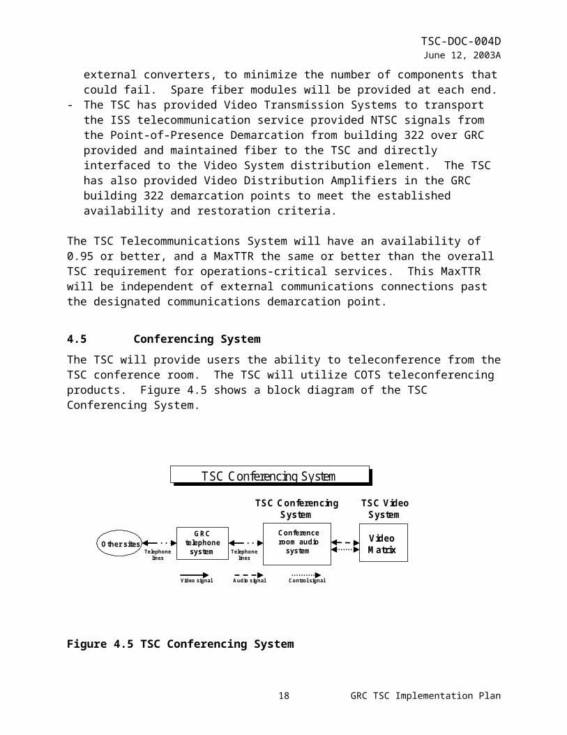
4.5Conferencing SystemThe TSC will provide users the ability to teleconference from the TSC conference room. The TSC will utilize COTS teleconferencing products. Figure 4.5 shows a block diagram of the TSC Conferencing System.
Figure 4.5 TSC Conferencing System
Users will have the capability to simultaneously videoconference with other NASA centers and one remote site. They will also be provided with an interface to the NASA videoconferencing network.
4.5.1 Conferencing System CapacityThe existing conference room teleconferencing package will be used with the existing connection into the TSC video matrix. The video matrix provides a graphical control display and also allows the conference room teleconferencing package to be used as an audio destination for the video matrix. NASA (agency) and GRC teleconferencing capabilities will be used to allow the conference system to connect to more than one destination at a time
4.5.2 Conferencing System Availability/RestorabilityTo meet the availability/restorability requirement specified in the TSC Requirements Document, the existing maintenance coverage of the teleconferencing hardware will be continued.
4.5.3 Remote Users Conferencing SystemsThe TSC will teleconference with remote users over standard telephone lines using standard telephone protocols. Remote users will provide their own teleconferencing packages or speakerphones.
13 GRC TSC Implementation Plan
IS:
Figure 4.5 TSC Videoconferencing System
VideoMatrix
TSC ConferencingSystem
Conferenceroom audio
system
Video signal Audio signal Control signal
TSC VideoSystem
TSC Conferencing System
GRCtelephone
systemOther sites
Telephonelines
Telephonelines
TSC-DOC-004DJune 12, 2003A
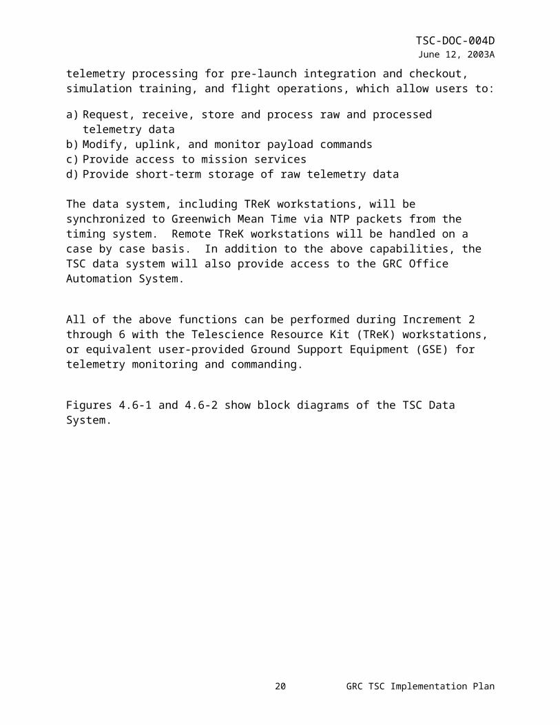
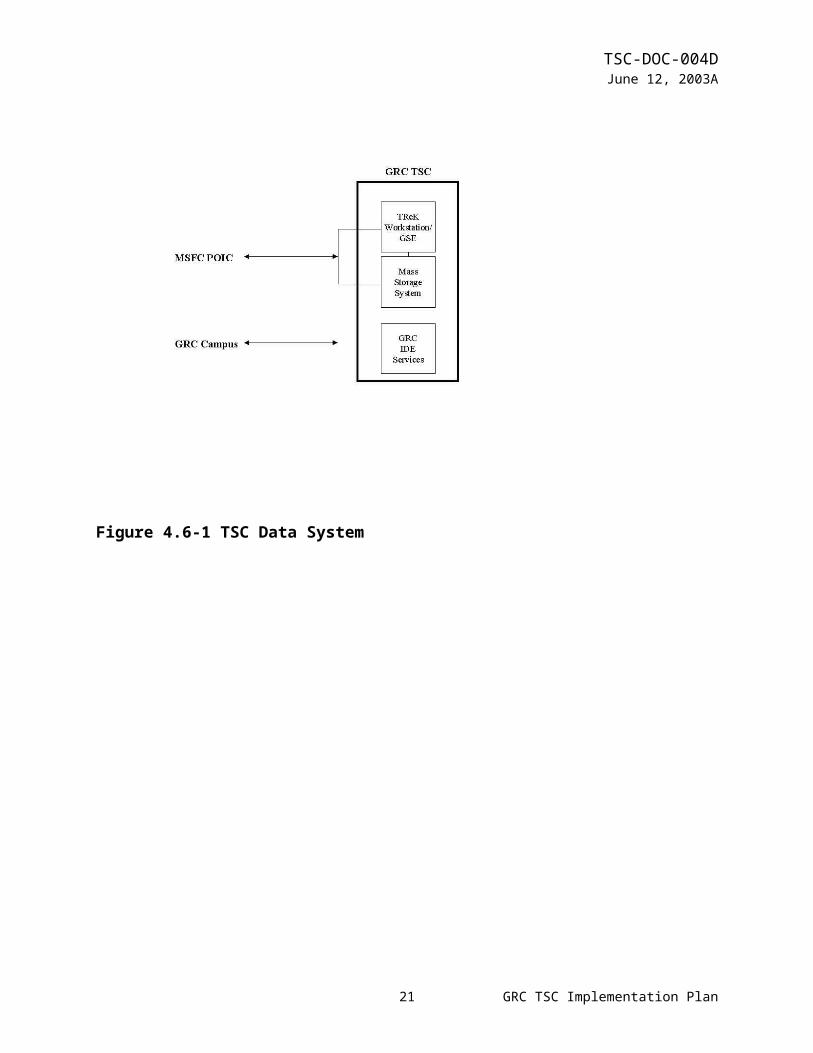
4.6Data SystemDuring increments 2 through 6, the GRC TSC will provide access to the POIC located at Marshall Space Flight Center (MSFC). The POIC comprises three major subsystems, the Payload Data Services System (PDSS), the Payload Planning System (PPS), and the Enhanced HOSC System (EHS). PDSS acquires, stores, and distributes ISS data to the EHS, IPs, TSCs, and other payload-unique facilities. The PPS provides a set of software tools to automate planning and schedule payload activities. The EHS performs command processing and real-time and near-real-time telemetry processing for pre-launch integration and checkout, simulation training, and flight operations, which allow users to:
a) Request, receive, store and process raw and processed telemetry datab) Modify, uplink, and monitor payload commandsc) Provide access to mission services d) Provide short-term storage of raw telemetry data
The data system, including TReK workstations, will be synchronized to Greenwich Mean Time via NTP packets from the timing system. Remote TReK workstations will be handled on a case by case basis. In addition to the above capabilities, the TSC data system will also provide access to the GRC Office Automation System.
All of the above functions can be performed during Increment 2 through 6 with the Telescience Resource Kit (TReK) workstations, or equivalent user-provided Ground Support Equipment (GSE) for telemetry monitoring and commanding.
Figures 4.6-1 and 4.6-2 show block diagrams of the TSC Data System.
14 GRC TSC Implementation Plan

TSC-DOC-004DJune 12, 2003A
Figure 4.6-1 TSC Data System
15 GRC TSC Implementation Plan
TSC-DOC-004DJune 12, 2003A
Figure 4.6-2 TSC Mass Storage System
16 GRC TSC Implementation Plan

TSC-DOC-004DJune 12, 2003A
4.6.1 Data System WorkstationsThe TSC will provide access to the POIC using either X-Windows software and/or a Web browser that is hosted on either the user’s ground support equipment (GSE) or TSC provided TReK workstations. TReK workstations will be provided for users located in the TSC, off-line users, and remote users by the TSC. These workstations provide the following capabilities:
a. Telemetry acquisitionb. Real-time telemetry requestc. Stored telemetry retrieval and processingd. Telemetry processinge. Exception monitoringf. Telemetry storage and retrievalg. Telemetry monitoring and manipulationh. Command capabilitiesi. Database capabilitiesj. Utilitiesk. Help functionsl. Access to the Payload Data Librarym. Access to the Payload Planning Systemn. Application Programming Interfaceo. Autoinstall of TReK softwarep. TReK operating configurations
Additional information concerning TReK capabilities can be found in the POIC Capabilities Document, SSP 50304. If the user desires to use user provided GSE, it will be their responsibility to obtain, integrate, and test their GSE to ensure its compatibility with the POIC. A complete description of POIC capabilities is provided in the POIC Capabilities Document (SSP 50304). POIC interfaces are described in detail in the POIC to Generic User Interface Definition Document (SSP 50305).
4.6.1.1 Data System CapacityThe TSC will provide simultaneous service for 2 independent, online operations (real-time operations, simulations, or training). for a maximum of 70 potential users (35 per operation) , and at any given time, a maximum of 70 simultaneous users (35 per operation). Implementation of this simultaneous service is TBD <TBD-1>.
4.6.1.2 Data System Availability/RestorabilityTo meet the availability and restorability requirements specified in the TSC Requirements Document, the TSC will configure TReK workstations with an operating system and appropriate COTS products per documentation on the TReK web site. This configuration is identified as the TSC’s Baseline TReK Configuration (BTC). The TSC will assist users in configuring the working environment on their TReK workstations, including databases, per their application specific needs. It will be the user’s responsibility to guarantee the integrity
17 GRC TSC Implementation Plan
TSC-DOC-004DJune 12, 2003A
of the content of their application specific software, including databases. TReK workstations will be backed up at regular intervals to ensure against system failure, per the procedures documented in the TSC Users Guide. In addition, the TSC will maintain at least two warm spare TReK workstations. Spare workstations will be configured with a BTC. Application specific software can then be layered on top of the BTC to restore an operational TReK workstation. TReK workstations will have a MaxTTR of 2 hours during day shift, and 12 hours if failure occurs during other shifts.
The TSC will maintain a mass storage system to store telemetry data. The server will be RAID based. It will have redundant power supplies and the major components will be hot swappable. The server will be powered with a UPS. The TSC data system will have an availability of 0.95 or better, excluding end user-induced faults, and a MaxTTR equal to or better than the overall TSC requirement for operations-critical services.
The TSC will maintain a server on the CSD External Services LAN. This server will be used for the distribution of the science data for the payloads. The server availability and security will be dependent on CSD. The TSC will maintain regular back ups and power the server on a UPS.
Workstations used exclusively for the GRC Office Automation System will have a MaxTTR of 8 day shift hours after reporting the failure. Printers are considered operations-noncritical, and will have a MaxTTR of 3 hours during day shift, and next day shift if failure occurs during other shifts.
4.6.2 TelemetryThe TSC will provide users with TReK workstations which have the capability to acquire telemetry from PDSS and EHS. TReK workstations have the capability to ingest CCSDS packets that are transmitted from PDSS at the rate of up to 2 Mbps. TReK workstations also have the capability to ingest POIC processed telemetry as user defined Ground Support Equipment packets and ground ancillary GSE packets. Refer to the POIC Capabilities Document for a description of the types of processed telemetry that are available to users and a description of the GSE packet request and distribution capabilities. Once telemetry has been ingested, users can store, process, and display the telemetry using a combination of MSFC developed TReK software and recommended COTS products that are installed on the TReK workstation. TReK telemetry processing software requires that the user’s CCSDS packet structures are MSFC-STD-1274 compliant and the telemetry database definitions are MSFC-DOC-1949 compliant. For more information regarding TReK telemetry processing capabilities, read the POIC Capabilities Document.
4.6.2.1 Telemetry CapacityTelemetry capabilities at the TSC will be available for a maximum of 70 potential telemetry users (35 per operation), and at any given time, a maximum of 70 simultaneous telemetry users (35 per operation).
18 GRC TSC Implementation Plan

TSC-DOC-004DJune 12, 2003A
4.6.3 CommandingCommanding during Increment 2 through 6 will use an X-window type interface through an EHS machine at the MSFC HOSC.
The TSC will provide users with the capability to update modifiable commands and request command uplinks via an X-Windows interface to the POIC. The X-windows interface software will be provided on TSC-provided TReK workstations. Note that all user command definitions will be required to be resident in the POIC command database. In addition to command update and command uplink, command users will be able to monitor command responses via the POIC command track application, which is also an X-windows interface. Web browser software will also be provided on the TSC-provided TReK workstation to allow users access to the POIC command delog application. For more information regarding POIC command capabilities, refer to the POIC Capabilities Document.
4.6.3.1 Commanding CapacityCommand capabilities at the TSC will be available for a maximum of 40 potential commanding users (20 per operation), and at any given time, a maximum of 30 simultaneous commanding users (15 per operation).
4.6.4 Mission ServicesThe TSC will provide the capability to remotely access the Payload Data Library (PDL), the Payload Information Management System (PIMS), and the Payload Planning System (PPS). PDL is an electronic ISS User Requirements Collection and Management System that is used to collect and summarize user requirements. PIMS is an electronic information system that is used by payload users to prepare for and/or re-plan increment execution. PIMS capabilities are available through a web interface. PPS is an integrated set of hardware and software used to develop payload operations plans to support the execution of onboard payload operations. Access to these system services can be obtained by using software installed on TReK workstations. Refer to the POIC Capabilities Document, SSP 50304, for more detailed information about the function and use of these tools.
4.6.5 Storage of Telemetry DataA server class system will be available at the TSC to store raw telemetry. The raw data will be routed from the PDSS at MSFC to the GRC TSC using a dedicated wide area network (WAN). The TSC will then route the data to the payload developers GSE and to mass storage system. There will be two NT servers to split the load of ingesting and storing the telemetry data. The TReK software will be used to grab the packets and store them on the file servers. A minimum of 90 days of raw telemetry data will be retained before the data will be removed from the mass storage system. The TSC will not archive the telemetry data before it is deleted from the mass storage system. The payload developer will have time to create digital copies of their raw data for their own archival before the data is removed from the system.
19 GRC TSC Implementation Plan
TSC-DOC-004DJune 12, 2003A
The mass storage server will have the capability to retrieve the raw telemetry data and resend it upon request to a user’s GSE. The TReK software interface will be used to request the data that is available on the mass storage server. The data will be retrieved and sent to the requested payload developer’s GSE of choice within the TSC mission network.
In addition, a limited amount of telemetry data will be able to be stored locally on a TReK workstation. Refer to the TReK web site and the POIC Capabilities Document, SSP 50304, for more details.
4.6.5.1 Mass Storage Data CapacityThe capacity of the mass storage system is approximately 250 GB. Each NT server which is part of the mass storage system will have approximately 125 GB of total storage.
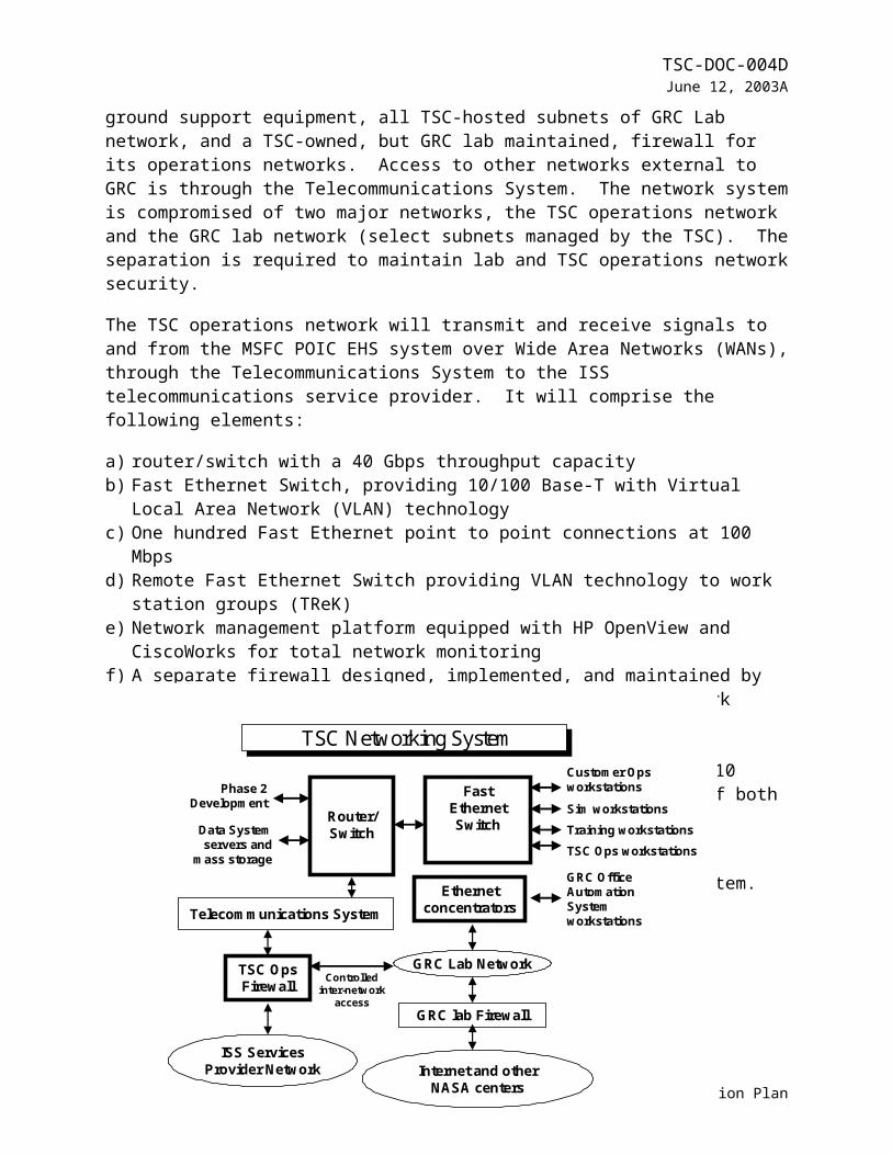
4.7Networking SystemThe TSC Networking System comprises all the internal LANs that interconnect the TSC Data System and customer-provided operations ground support equipment, all TSC-hosted subnets of GRC Lab network, and a TSC-owned, but GRC lab maintained, firewall for its operations networks. Access to other networks external to GRC is through the Telecommunications System. The network system is compromised of two major networks, the TSC operations network and the GRC lab network (select subnets managed by the TSC). The separation is required to maintain lab and TSC operations network security.
The TSC operations network will transmit and receive signals to and from the MSFC POIC EHS system over Wide Area Networks (WANs), through the Telecommunications System to the ISS telecommunications service provider. It will comprise the following elements:
a) router/switch with a 40 Gbps throughput capacityb) Fast Ethernet Switch, providing 10/100 Base-T with Virtual Local Area Network (VLAN)
technologyc) One hundred Fast Ethernet point to point connections at 100 Mbpsd) Remote Fast Ethernet Switch providing VLAN technology to work station groups (TReK)e) Network management platform equipped with HP OpenView and CiscoWorks for total
network monitoringf) A separate firewall designed, implemented, and maintained by the GRC lab services
responsible for the main lab network firewall
The TSC subnets of the GRC lab network are distributed on 10 Base-T concentrators within the TSC. The common element of both networks is the Category 5 compliant twisted-pair cable infrastructure and patch panel.
Figure 4.7 shows a block diagram of the TSC Networking System.
20 GRC TSC Implementation Plan
Controlledinter-network
access
TSC Networking System
Router/Switch
FastEthernetSwitch
Customer Opsworkstations
Sim workstationsTraining workstationsTSC Ops workstations
Data Systemservers and
mass storage
ISS ServicesProvider Network
GRC Lab Network
Phase 2Development
Telecommunications System
TSC OpsFirewall
Ethernetconcentrators
GRC lab Firewall
GRC OfficeAutomationSystemworkstations
Internet and otherNASA centers
TSC-DOC-004DJune 12, 2003A
Figure 4.7 TSC Networking System
21 GRC TSC Implementation Plan
TSC-DOC-004DJune 12, 2003A
4.7.1 Network System CapacityA scalable networking architecture will be deployed to meet the port requirements specified in the TSC Requirements Document. Each of the 100 individual 100 Mbps network connection on the TSC operations network will be interfaced into a group of Fast Ethernet switches and be organized into VLANs. These VLANs will be tied together in an OSI Layer 3 Backbone router/switch which will provide an aggregate throughput of 40 Gbps. Ports for the subnets of the GRC lab network will be provided on 10Base-T concentrator cards in a multiple card hub.
4.7.2 Network System Availability/RestorabilityTo meet the availability and reliability requirements for the TSC operations network specified in the TSC Requirements Document, both routers will be dual-homed to external networks. Both routers will also contain redundant processors, network interface boards and power supplies. Flexible VLAN technology will be used to provide simultaneous network connections for real-time mission operations, simulations, and development. COTS software products will be used to perform real-time network management and monitoring. The TSC network system will have an availability of 0.98 or better, and a MaxTTR equal to or better than the overall TSC requirement for operations-critical services.
To meet the availability and reliability requirements for the TSC-hosted subnets of the GRC lab network specified in the TSC Requirements Document, spares for concentrator cards and separate hubs will be maintained on-site. The TSC network system will have a MaxTTR equal to or better than the overall TSC requirement for operations-noncritical services.
4.7.3 Network IsolationThe subnets of the GRC lab network and the TSC operations network will be physically isolated. Limited inter-network connectivity will be allowed between the GRC lab network firewall and the TSC operations network firewall. This inter-network communication will be jointly controlled by the TSC and GRC lab network services
4.8Timing SystemThe TSC Timing System is synchronized to a timing signal that originates from the Global Positioning System (GPS). The GPS is a worldwide navigational and timing satellite system. GPS signals are received at GRC through a satellite ground terminal and distributed throughout the Center via an internal cable plant in the IRIG-B format. At the TSC, the IRIG-B signal is available for redistribution, if required, but Network Timing Protocol (NTP) packets are the primary output. NTP packets are generated and distributed over the TSC Network System for use by the TSC Data, Network, and Ground Track Systems and user-provided ground support equipment. Video displays in all mission operations areas show both Greenwich Mean Time and ISS on-board time in days, hours, minutes, and seconds.
22 GRC TSC Implementation Plan
TSC-DOC-004DJune 12, 2003A
Figure 4.8 shows a block diagram of the TSC Timing System.
Figure 4.8 TSC Timing System
4.8.1 Timing System CapacityTwo independent sets of timing displays will be provided to the users. Room displays will show the real-time operation in progress. Simulation time displays will be available on audio-video station monitors. ISS referenced times will also be provided to users at remote sites via TReK.
4.8.2 Timing System Availability/RestorabilityThe TSC timing system will meet the availability and restorability requirements of the TSC Requirements Document by using two separate PCs. The PC’s will generate the displays and be servers for NTP packet requests. Systems depending on NTP packets will be able to select both servers and therefore automatically fail over to the other server. A spare PC will be available on site. The portions of the timing system that create and distribute NTP packets to other TSC systems and TSC users will have a MaxTTR equal to or better than the overall TSC requirement for operations-critical services. All other portions of the timing system will have a MaxTTR equal to or better than the overall TSC requirement for operations-noncritical services.
23 GRC TSC Implementation Plan

TSC-DOC-004DJune 12, 2003A
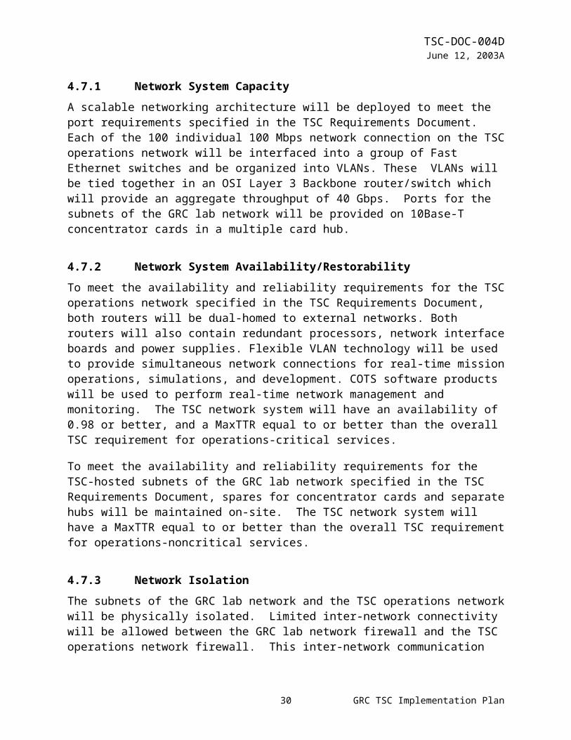
4.9Ground Track SystemThe TSC Ground Track System will provide a display of TDRS AOS/LOS times and a graphical depiction of vehicle on-orbit, and distribute these displays to all users in the TSC via the TSC video matrix. The TSC Ground Track System uses primary and secondary displays. The primary display is generated by a Unix-based system that is used by the MSFC POIC and JSC MCC, which incorporates a real-time data feed. Hardware for the JSC/MSFC system will be purchased per JSC/MSFC specifications. NASA-developed software will be provided by JSC and MSFC. COTS software will be purchased by GRC TSC. Any other required COTS products will be purchased by GRC TSC. The secondary display is a PC-based system and will be maintained for a backup and simulation capability. The PC hardware will be updated for Year 2000 compliance. Software will be obtained through the author’s Website. The displays will be available at every TSC audio-video station and will also be selectable at other video destinations through the TSC video matrix. Timing signals will be provided by the TSC timing system.
Figure 4.9 shows a block diagram of the TSC Ground Track System.
Figure 4.9 TSC Ground Track System
24 GRC TSC Implementation Plan
TSC-DOC-004DJune 12, 2003A
4.9.1 Ground Track System CapacityTwo independent sets of ground track displays will be available to the user. A display of TDRS AOS/LOS times and a graphical depiction of vehicle on-orbit will be provided to remote sites.
4.9.2 Ground Track System Availability/RestorabilityThe TSC Ground Track System will have an availability of 0.90 or better, and a MaxTTR equal to or better than the requirement for overall TSC operations-noncritical services.
4.10 Facility
4.10.1 Facility OverviewFor Increment 2 through 6, the TSC will occupy the existing facilities in the north wing of Building 333.
The main operations room, the secondary operations room, and the operations control room will be capable of providing two concurrent operations and a training activity. Other areas include an initial TReK staging area, an equipment room, videoconferencing/replanning room, a critical spares storage/technician repair area, a document library, and an HVAC area. Heating, ventilation, and air conditioning (HVAC) and electrical power services will be provided to all areas. Electrical power services will be single-fault tolerant or use multiple sources when supporting operations-critical areas.
25 GRC TSC Implementation Plan
TSC-DOC-004DJune 12, 2003A
Figure 4.10 shows a block diagram of the first floor rooms of the TSC Facility.
Figure 4.10 TSC Facility Overview
26 GRC TSC Implementation Plan

TSC-DOC-004DJune 12, 2003A
The following areas are provided by the TSC for its users, staff, and equipment:
a) Room 150 and 102/104 are operations areas for 24x7 science activities [4000 square feet]. These rooms also provide the location for initial (Phase 1) training [1000 square feet], and printer, scanner, copier, and fax supplies used for general purpose office functions that are required for users on console [100 square feet]
b) Room 153 is the operations control area for the 24x7 TSC Operations Support Group staff [300 square feet]
c) Room 151 is the communications interface and data system server area [1300 square feet]d) Room 155 provides an area for the TSC staff to perform data system related tasks, such as
data system development and validation, system administration, and workstation staging [250 square feet]
e) Room 108 is a conference room designated to provide an area for videoconferencing, replanning, and a shift handover function for activities that need to happen off-console [500 square feet]
f) Building 333 Annex provides storage for spares and equipment for spared system elements and modules that are not kept powered up [500 square feet]
g) Room 203 provides storage for configuration managed copies of TSC and ISS documents and drawings to be maintained [50 square feet]
h) Vending machine area i) Observation/visitors area sufficient for 25 people at a time to view the operations in progress
without disturbing the participantsj) TSC staff office and administrative area for 15 persons [1000 square feet]
4.10.2 Facility CapacityThe TSC will support up to 35 local users for each operation (total 70 local).
4.10.3 Facility User AccommodationsThe TSC will provide operations area accommodations, such as consoles or tables, chairs, telephones, and storage cabinets, for users in the operations areas. Accommodations will also be provided for public affairs interviews. Parking for users will also be provided.
4.10.4 MaintenanceThe TSC oversees internal and external maintenance, as well as upgrades of hardware and software. An updated inventory listing is maintained and provided to the NASA Equipment Management System (NEMS). The TSC performs periodic assessments on equipment to determine whether rollover should occur. Performing maintenance shall be evaluated against new equipment cost. Inventory and supplies considerations shall be evaluated in terms of availability of storage versus usage.
27 GRC TSC Implementation Plan

TSC-DOC-004DJune 12, 2003A
4.11 OperationsTSC Operations can be separated into three major activities: pre-increment operations, increment operations, and post-increment operations. Pre-increment operations begin 24 months prior to an increment. Increment operations run for the entire increment, if required by TSC users. Post-increment operations last for 30 days after the completion of the increment.
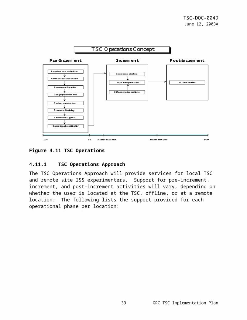
Figure 4.11 shows a diagram of TSC Operations, including pre-increment, increment, and post-increment activities.
Figure 4.11 TSC Operations
4.11.1 TSC Operations ApproachThe TSC Operations Approach will provide services for local TSC and remote site ISS experimenters. Support for pre-increment, increment, and post-increment activities will vary, depending on whether the user is located at the TSC, offline, or at a remote location. The following lists the support provided for each operational phase per location:
28 GRC TSC Implementation Plan

TSC-DOC-004DJune 12, 2003A
a) Pre-increment support1) At the TSC, engineering and technical staff will be provided for simulations, ground
support personnel training, pre-increment development on TSC-furnished equipment, and setup, test, validation, and certification of all GSE for experiment teams at the TSC.
2) At offline locations, the same support is provided as at the TSC, but the TSC staff will be at the offline site during initial setup. Other activities will be supported from the TSC.
3) At remote locations, the TSC staff will provide minimal advice. Setup, training, testing, validation, and certification are the responsibility of MSFC.
b) Increment support1) At the TSC, support will be provided on a continuous basis.2) At offline locations, support will be provided from the TSC (not at the offline site)3) At remote locations, the TSC staff will provide minimal advice. Other required services
will be provided by MSFC.c) Post-increment support
1) At the TSC, support will be provided during the day shift.2) At offline locations, support will come from the TSC (not at the offline site) during the
day shift.3) At remote locations, support will be provided during the day shift.
4.11.2 TSC Pre-increment Operations ActivitiesDuring requirements definition, users submit a mission request for to the TSC project manager no later than I-24. Detailed user requirements are collected through the PDL in the following manner: real time and voice requirements at I-23, EHS/POIC requirements at I-15, and TSC specific requirements at I-10. Users participate in periodic Telescience Working Group Meetings to clarify user requirements.
During Increment 2 through 6, users will submit their ground operations requirements through MSFC using the Payload Data Library (PDL). PDL submittals will be via paper input rather than electronic means until completion of the automated PDL system in late year 1999 or early year 2000.
During preliminary assessment, the TSC staff performs an assessment study of the user requirements. Increment specific documents are developed, which when complete identify new system requirements. These documents are reviewed and agreed to by the user.
During resource allocation, the TSC staff performs a detailed study of space allocations (including user and TSC staff work areas), equipment allocations (including TReK workstations, printers, and audio/video stations), common services, and new equipment considerations.
During increment system design and procurement, a system design is developed to include new and existing equipment, and detailed drawings of this design are developed. When the design is completed, procurement begins for new equipment purchases.
During system preparation, user work areas are prepared with TSC-provided equipment and Ground Support Equipment (GSE). Interface and system verification activities are performed, operation procedures are developed, and security assignments are issued and activated.
29 GRC TSC Implementation Plan
TSC-DOC-004DJune 12, 2003A
During personnel training, the TSC provides staff and user training on the Audio and Video Systems, TReK workstations, common services equipment, and increment specific equipment, procedures, and services.
Simulations begin at I-10 months. The simulations identified are listed below:
1. Cadre/PD Team Operations/Interfaces/Products Simulation2. Integrated Payload Only Simulation3. US/PCC/PD/Crew Simulation4. Joint Multi-Segment Training Simulation
During operational certification, the TSC staff and users are certified prior to increment support per the Payload Ground Support Personnel Training and Certification Plan. The TSC will hold an Operational Readiness Review (ORR) prior to each increment.
4.11.3 TSC Increment Operations ActivitiesIncrement operations begin when user experiments are powered up, or per special user requirements. Increment operations end when user experiments are completed, or per special user requirements. Increment operations can be separated into three categories: operations startup, nominal operations, and off-nominal operations.
Operations startup will begin after the interfaces and systems are tested and found to be operationally ready. The TOC and technician go through the operations startup check list to power up all TSC systems and activate all facility services.
During nominal operations, the TSC will be operational 24 hours per day, based on user requirements. TSC staffing during this period will consist of an Operations Support Group (OSG) and an Engineering and Technical Support Group (ESTG). TSC users interface with the TOC to request support or report anomalies during increment operations.
During off-nominal operations, the TOC and technician will assess the severity of the problem or anomaly, assign a criticality level, and determine a course of action. ETSG personnel will be available during off hours on a call-in basis to work off-nominal operations.
4.11.4 TSC Post-increment Operations ActivitiesDuring post-increment operations, TSC deactivation activities occur, per user requirements. The TSC staff and the users hold a debriefing shortly after deactivation. Users remove their GSE within 10 working days. The TSC will retain stored user data for 30 calendar days. TSC technicians begin to reconfigure workareas for the next increment.
30 GRC TSC Implementation Plan
TSC-DOC-004DJune 12, 2003A
4.12 Security Assessment ProcessThe security program at the TSC is a rule-based risk-management process. The TSC security approach uses, virtual LAN’s, a firewall (with access list, auditing software tools), and management controls to form an integrated approach to security. The TSC will have procedures and acceptable rules and plans to insure the protection of proprietary information and the preservation of TSC services. These plans are the Facility Security Operations Plan, Computer Security Plan, Emergency and Contingency Plan, and the COMSEC Security Plan. General site security procedures, acceptable site security rules, and physical security information for use during Space Station increments will reside in the TSC Users Guide. Computer security, incident response policies and procedures will be incorporated into both TReK server and workstation data files. A downloaded hardcopy from the server will act as backup in case access is denied. A security specification document will be prepared if this event occurs. GRC TSC will be responsible for the security certification at remote sites. Figure 4.12 shows a block diagram of TSC Security Risk Management.
Figure 4.12 TSC Security Risk Management
31 GRC TSC Implementation Plan
TSC-DOC-004DJune 12, 2003A
4.13 Training and Certification
4.13.1 Training ProcessCertified TSC staff will provide training to all Ground Support Personnel at the TSC. User training will consist of
a) Generic operations training, including training in operations of TSC-provided voice and video systems, and security
b) Increment specific training, including training in operations that are coordinated with MSFC, JSC, and the crew
TSC staff training will consist of detailed TSC systems operation, maintenance, and anomaly resolution for all TSC facility and equipment systems.
Training methods will include classroom exercises, workbook exercises, computer-based training, hands-on exercises, simulations, and on-the-job training.
The following training template will be followed:
a) TSC to payload developer generic training will be completed prior to the start of simulationsb) TSC staff facility training will be completed prior to the start of simulationsc) Payload developer console operation simulations will begin at I-10d) Integrated Payload only simulations will begin at I-8e) US PCC/POIC/TSC/Crew simulations will begin at I-6f) Joint Multi-Segment Training simulations will begin at I-3
4.13.2 Certification PlanCertification for the TSC facility, staff, and users will occur during training, testing, and simulation activities. Staff and user certification will be in accordance with programmatic requirements to be defined in the Payload Ground Support Personnel Training and Certification Plan, MSFC-PLAN-2848. All TSC staff and user training and certification will be tracked and verified per a data base administered by the TSC Training Lead, per the GRC TSC Training Plan. Training not administered at the TSC will need to be verified, certified, and reported to the training lead.
Ground Support Personnel must be certified prior to the beginning of each increment. All TSC facility and operational systems must be certified prior to the Operational Readiness Review (ORR). The TSC will hold an ORR prior to each increment to adhere to the Certification of Flight Readiness (CoFR) process.
Re-certification of the TSC facility, staff, and users will be performed prior to each increment by reviewing requirements, and performing any additional increment specific training required.
32 GRC TSC Implementation Plan

TSC-DOC-004DJune 12, 2003A
5.0ACRONYM LISTING
API Applications Programming InterfaceATM Asynchronous Transfer ModeATV Advanced Television COTS Commercial Off-The-ShelfEHS Enhanced HOSC SystemETSG Engineering and Technical Support GroupFDDI Fiber Distribution Data InterfaceGMT Greenwich Mean TimeGPS Global Positioning SystemGRC Glenn Research CenterGSE Ground Support EquipmentGSFC Goddard Space Flight CenterGUI Graphical User InterfaceHOSC Huntsville Operations Support CenterICD Interface Control DocumentIGSS International Ground Systems SpecificationsIRIG Inter Range Instrumentation GroupISDN Integrated Services Digital NetworkISS International Space StationJSC Johnson Space CenterMET Mission Elapsed TimeMPEG Motion Picture Equipment GroupMSD Microgravity Science DivisionMSFC Marshall Space Flight CenterNASA National Aeronautics and Space AdministrationNISN NASA Integrated Services NetworkOSG Operations Support GroupPDL Payload Data LibraryPDRD Payload Data Requirements DocumentPOIC Payload Operations Integration CenterRAID Redundant Arrays of Independent DisksSGI Silicon Graphics Inc.TBD To Be DeterminedTIP Telescience Implementation PlanTReK Telescience Resource KitTRD TSC Requirements DocumentTSC Telescience Support CenterUF Utility FlightVLAN Virtual Local Area NetworkWAN Wide Area Network
33 GRC TSC Implementation Plan

TSC-DOC-004DJune 12, 2003A
6.0GLOSSARY
Availability The proportion of time that an item is capable of operating to specifications within a large time interval.
Day Shift Normal business hours 5 days per week 8 hours during the day (non-holiday).
Element An element is part of a system (referencing criticality).
Generic Operations Training that is not increment-specific and is provided prior to any pre-Training increment support. Typically involves familiarization with ground
support equipment and services and operations protocols.
MaxTTR Maximum Time To Restore. The time required to restore lost services in mean + 1.5 sigma failure situations (approximately 85% assuming normal probability distribution).
Offline Operations Area An offline operations area is an area used for experiment operations that
are not within the TSC but still within NASA GRC or areas that are directly serviced by NASA GRC.
Operations-Critical Services Services that when lost will significantly impact multiple/all experiments
or cause catastrophic loss of data to one experiment. All TSC systems, elements, or services used in real-time operations within the TSC are classified as operations-critical. All TSC-provided systems, elements, or services at remote sites are operations-critical only if the operations capability exists exclusively at that site.
Operations- Noncritical Services Services that when lost will not significantly impact multiple experiments
or cause catastrophic loss of data to one experiment. Also applies to most simulation and training support services. All TSC systems, elements, or services used exclusively in training or simulations are classified as operations-noncritical. TSC systems, elements, or services whose functions are duplicated in other systems or services, excluding system redundancies, are classified as operations-noncritical. TSC systems, elements, or services used exclusively at offline operations areas or remote sites are classified as operations-noncritical, except when the remote site has exclusive operations capability.
34 GRC TSC Implementation Plan

TSC-DOC-004DJune 12, 2003A
[TSC] Phase 1,2 TSC development and support phases as defined in the TSC Project Plan. Phase 1 includes ISS Increments 2 through 6; Phase 2 includes ISS Increments 7 and beyond.
Remote site An operations area that is outside of NASA GRC or an area that is Operations Area directly serviced by NASA GRC (i.e., Aerospace Park).
Rollover A method of periodic replacement of hardware to prevent obsolescence and curtail maintenance costs (4 to 6 years typical rollover).
35 GRC TSC Implementation Plan
TSC-DOC-004DJune 12, 2003A
APPENDIX A TO BE DETERMINED (TBD) ITEMSTBD items are items whose full definitions are still under discussion.
Section Number TBD Item4.6.1.1 Data System Capacity <TBD-1> Implementation of simultaneous
service for two independent, online operations4.6.5 Storage of Telemetry Data <TBD-3> Implementation of archival device4.6.5.1 Storage of Telemetry Data Capacity <TBD-4> Capacity, utilization, and management
of the mass storage unitMultiple 4.6.2.1.3, 4.6.2.1.4, (TRD paragraphs from matrix)
<TBD-7> Future ECR to be generated to update the TIP, paragraphs 4.6 and/or 4.7, pending outcome of Data Distribution Subsystem Architecture.
36 GRC TSC Implementation Plan
TSC-DOC-004DJune 12, 2003A
APPENDIX B TRD TO TIP REQUIREMENT CROSS REFERENCE MATRIXThe following matrix provides a cross-reference between requirements in the TSC Requirements Document (TRD) and their implementation in the TSC Implementation Plan (TIP).
37 GRC TSC Implementation Plan

TSC-DOC-004DJune 12, 2003
TRD Paragraph TIP Paragraph4.0 REQUIREMENTS AND CONSTRAINTSThis section describes the requirements and constraints applicable to the entire life cycle of the GRC TSC used to support the ISS program. Requirements for other programs are contained in Appendix A. Requirements that require exception for TSC Phase 1 are noted. Requirements in this document are applicable only to systems or services within the TSC, unless otherwise specified.
(not applicable)
4.1 Overall TSCThe GRC TSC shall provide the capability to support real-time operations, simulated operations, and onsite ground support personnel training. This includes conducting operations of payloads, experiments, and instruments in the TSC.
4.1 Overall TSCThe TSC will be phased to support ISS Increment 2 through 6 (TSC Phase 1) operations within building #333 at the NASA GRC and from locations offline and remote to the TSC. ISS operations support will include real-time operations, simulated operations, and onsite ground support personnel training.
4.1.1 Overall TSC CapacityThe TSC shall have the capacity to simultaneously supply services to:a) Two full-scale operations (real-time and/or simulated) of 75 users at the TSC per operation (150 users total) [Phase 1: 30 users at the TSC per operation (60 users total)]b) Thirty users at 15 remote sites per operation (60 users at 30 remote sites total) [Phase 1: No remote operations requirements] c) Fifteen users at 5 offline operations areas total [Phase 1: 5 users at 2 offline operations areas] d) Generic operations training for 20 users. [Phase 1: Not a requirement]
4.1.1 Overall TSC CapacityPhase 1 of the TSC will be designed to provide the following services simultaneously to users:a) Two full-scale operations (real-time and/or simulated) for 30 usersb) Five users at 2 offline operations areas
4.1.2 Overall TSC Restorability4.1.2.1 Criticality ClassificationsThe TSC systems, elements, and services shall be classified as either operations-critical or operations-noncritical for the purposes of restorability.
4.1.2 Overall TSC RestorabilityTSC systems and services are classified as either operations-critical or operations-noncritical for purposes of restorability.The definitions of operations-critical and operations-noncritical
38 GRC TSC Implementation Plan

TSC-DOC-004DJune 12, 2003
TRD Paragraph TIP Paragraphare as follows:
Operations-critical systems and services are those that, when lost, will significantly impact multiple/all experiments or cause catastrophic loss of data to one experiment. All TSC systems, elements, or services used in real time operations within the TSC are classified as operations-critical.All TSC-provided systems, elements, or services at remote sites are operations-critical, only if the operations capability exists exclusively at that site.
Operations-noncritical systems and services are those that, when lost, will not significantly impact multiple experiments or cause catastrophic loss of data to one experiment. This also applies to most simulation and training support services. All TSC systems, elements, or services used exclusively in training or simulations are classified as operations-noncritical. TSC systems, elements, or services whose functions are duplicated in other systems or services, excluding system redundancies, are classified as operations-noncritical. TSC systems, elements, or services used exclusively at offline operations areas or remote sites are classified as operations-noncritical, except when the remote site has exclusive operations capability.The Maximum Time to Restore Service (MaxTTR) for operations-critical TSC services will be 4 hours during day shift, and 8 hours during other shifts. The MaxTTR for operations noncritical services (or systems in operations noncritical usage) will be 8 hours during day shift, and next day shift, for failures during other shifts. These MaxTTR numbers will be achieved through the following approach:a. On-site whole unit replacements and card level spares
39 GRC TSC Implementation Plan

TSC-DOC-004DJune 12, 2003
TRD Paragraph TIP Paragraphb. A trained technical staff to perform failure analysis, fault
isolation, equipment replacement, and problem tracking and resolution
c. Lab service and vendor maintenance contracts to provide on-call service
4.1.2.1.1 Operations-Critical Classificationa) All TSC systems, elements, or services used in real-time
operations within the TSC shall be classified as operations-critical, unless otherwise specified in this document.
b) All TSC-provided systems, elements, or services at remote sites shall be considered operations-critical, only if the operations capability exists exclusively at that site.
4.1.2 Overall TSC Restorability(see Above)
4.1.2.1.2 Operations-Noncritical Classificationa) All TSC systems, elements, or services used exclusively in
training or simulations shall be classified as operations-noncritical.
b) Systems, elements, or services whose functions are duplicated in other systems or services, excluding system redundancies, shall be classified as operations-noncritical.
c) Systems, elements, or services used exclusively at offline operations areas or remote sites shall be classified as operations-noncritical, except as noted in the operations-critical requirements for remote sites.
4.1.2 Overall TSC Restorability(see above)
4.1.2.2 TSC Operations-Critical Services RestorabilityThe TSC shall have a Maximum Time to Restore Service (MaxTTR) for operations-critical services of:a) Four hours during day shiftb) Eight hours during other shifts
4.1.2 Overall TSC Restorability(see above)
4.1.2.3 TSC Operations-Noncritical Services RestorabilityThe TSC shall have a MaxTTR for operations-noncritical services
4.1.2 Overall TSC Restorability(see above)
40 GRC TSC Implementation Plan
TSC-DOC-004DJune 12, 2003
TRD Paragraph TIP Paragraph(or systems in operations-noncritical usages) of:a) Eight hours during day shiftb) Next day shift if failure occurs during other shifts4.1.2.4 Overall TSC Life CycleThe TSC shall design the facility to have a 15 year life. (Scheduled equipment replacement may be used to meet this requirement.)
4.1.5 Sustaining EngineeringThe overall TSC life expectancy is designed for 15 years, with equipment replacement every four to six years. To this end, the TSC will employ a method of sustained engineering through continuous process review and planned equipment turnover. Continuous process review involves modification and upgrade of existing systems to meet TSC user needs on an incremental basis. Planned equipment turnover allows for the periodic replacement of hardware in accordance with estimated maintenance requirements and age limitations. It also allows the TSC to integrate newer technologies required for user support.
4.1.3 TSC User ServicesThe TSC shall provide users services as follows:a) Parking as specified in 4.10.4b) Operations area accommodations as specified in 4.2.2, 4.3.3.2,
4.6.1.2, and 4.10.5.c) <TBD-3> public affairs accommodations
4.10.3 Facility User AccommodationsThe TSC will provide operations area accommodations, such as consoles or tables, chairs, telephones, and storage cabinets for users in the operations areas. Accommodations will also be provided for public affairs interviews. Parking for users will also be provided.
4.1.4 TSC External InterfacesThe TSC shall establish external interfaces with the following to the extent necessary to meet the requirements of this document:a. MSFC POIC (HOSC)b. JSC (Building 8)c. GRC lab (network and timing services)d. NISN gateway at GRCe. Remote GRC-supported users [Phase 1: Not a requirement]
4.0 Implementation Approachb. All internal interfaces will be documented and controlled per the GRC TSC Configuration Management Plan. External interfaces described in the HOSC To GRC TSC ICD will be controlled by the GSCB at JSC. This document describes the external interfaces between the POIC and the GRC TSC. All other external interfaces will be described in the GRC TSC Configuration Management Plan.
4.2 Audio System 4.2 Audio System
41 GRC TSC Implementation Plan

TSC-DOC-004DJune 12, 2003
TRD Paragraph TIP ParagraphThe TSC audio system shall receive and distribute the following audio for TSC users and TSC supported remote sites: [Phase 1: remote site distribution is not a requirement.]a. Air-to-ground voice loopsb. Ground-to-ground voice loopsc. TSC-generated audio sources
The TSC has voice communications services available to its users during training, testing, simulation and mission operations. Voice communications are available between GRC, MSFC and JSC through the ISS voice loop service provider). Figure 4.2 shows a block diagram of the TSC Audio System.The TSC Audio System will perform the following functions:a) receive and transmit signals from and to the ISS voice loop
service provider.b) distribute individual voice loops to the Operator
Communications Panel,c) provide access to Channel Banks for TSC generated and
external audio sources, andd) provide an analog bridge and amplifiers to distribute voice
grade circuits from more than one source.A System Administration Terminal (SAT) will be used to configure and distribute voice loops, diagnostics, and security.
4.2.1 Audio System Capacity4.2.1.1 Audio System Voice Loop and Audio Source CapacityThe audio system shall provide a voice loop and audio source capacity of:a) Forty-eight external voice loops from the ISS voice circuit
provider per operation (96 voice loops total) [Phase 1: A total of forty external voice loops from the ISS voice circuit provider, including inter-facility and remote site voice loop.]
b) 12 inter-facility loops from the ISS voice circuit provider, [Phase 1: Inter-facility voice loop requirements included in a.)].
c) Twelve external voice loops from remote sites per operation (24 loops total). [Phase 1: Remote site voice loop requirements included in a)]
4.2.1 Audio System Capacity
The TSC audio system will accept voice loops for multiple operations, and then configure the system to distribute the correct voice loops to each audio station. The capability to interface with 72 loops (or other audio sources) will be provided by the DICES III element. Up to 40 audio stations will be provided within the TSC.Each audio station will be capable of selecting combinations of up to 30 pre-set loops by switches on the front panel of the audio station. Each station is intended to support two users, and provides two headset connections and independent audio controls. The DICES III system element will configure the
42 GRC TSC Implementation Plan

TSC-DOC-004DJune 12, 2003
TRD Paragraph TIP Paragraphc) Twelve internal training loopsd) Twelve TSC generated audio sources (bi-directional
capability; not distributed external to TSC audio system)
correct loops at each audio station, and provide the allowed permissions (talk/listen versus monitor only). The talk/listen capability versus monitor capability will be selected for each loop by the user within the permissions configured at that audio station.
4.2.1.2 Audio System Audio Station CapabilityThe audio system shall provide a capacity of:a. Forty-five onsite audio stations per operation (90 stations total)
[Phase 1: 20 onsite user audio stations per operation (40 stations total)]
b. Twenty onsite training operator audio stations [Phase 1: Not a requirement.]
c. Thirty users at 15 remote sites per operation (60 users at 30 remote sites total) [Phase 1: Not a requirement.]
d. Fifteen users at 5 offline operations areas total [Phase 1: Not a requirement.]
4.2.1 Audio System Capacity(see above)
4.2.2 Audio Station User InterfaceEach audio system station user interface shall meet the following requirements:a) Capable of accessing a minimum of 30 loops/sources in total
and at least 24 loops/sources simultaneouslyb) Allow 2 users simultaneous access at each stationc) Provide the user the capability to select monitor only and talk
and monitor for each loop and sourced) Provide independent volume control for each usere) Show voice activity on each loop and source [Phase 1: Not a
requirement]f) Restrict user access to approved loops/sources and talk
function as a function of individual stations and loops/sources
4.2.1 Audio System Capacity(see above)
4.2.3 Audio System Availability/Restorability
43 GRC TSC Implementation Plan
TSC-DOC-004DJune 12, 2003
TRD Paragraph TIP Paragraph4.2.3.1 Audio System Restorability4.2.3.1.1 Overall Audio System RestorabilityThe overall audio system shall have a MaxTTR the same or better than the overall TSC requirement for operations-critical services specified in 4.1.2.2.
4.2.2 Audio System Availability/RestorabilityTo meet the availability and restorability criteria specified in the TSC Requirements Document, the DICES III element will use redundant CPUs, internal busses, and power supplies. To meet the overall audio system restorability requirements, all modules and power supplies will be “hot” swappable, and most cards and modules will be spared locally. Restorability for end user equipment will be met by having spare items (headsets and audio stations) spared locally, and by having 24x7 TSC technician support when users are in the facility.
4.2.3.1.2 End User Equipment RestorabilityEnd user equipment located in the TSC, such as headsets and audio stations, shall have a MaxTTR of:a) One hour during day shiftb) Next day shift if the failure occurs during other shifts
4.2.2 Audio System Availability/Restorability(see above)
4.2.3.2 Audio System AvailabilityThe overall audio system shall have an availability of 0.95 or better.
4.2.2 Audio System Availability/Restorability(see above)
4.3 Video SystemThe TSC video system shall route and distribute video and corresponding audio, when available, from ISS and other sources to destinations within the TSC facility.
4.3 Video SystemThe TSC will provide users that require ISS real-time video as part of the operation requirements, a connection to the ISS video source through video distribution amplifiers that bypasses the video matrix. This will increase reliability of the ISS real-time video to the users that need it most.
The TSC will provide all other users access to the matrix video switching system. This will give the individual users at audio-video stations the ability to independently select the desired video for monitoring and recording. The user at the TSC will be able to select up 1 video channel.
44 GRC TSC Implementation Plan

TSC-DOC-004DJune 12, 2003
TRD Paragraph TIP ParagraphFigure 4.3 shows a block diagram of the TSC Video System.
The Phase 1 Video System will handle NTSC RS-170 composite video and S-video. For most users, this capability will be supplied through the TSC video matrix. Two channels of Real-time ISS video provided to the user. Users will be provided with views of ground track and time displays. Users will also be provided with views of the rooms that comprise the TSC facility, hallways that connect those rooms, and the Building #333 high bay. Users will have access to NASA TV, a TSC selectable local GRC Link video channel, and a VCR to be used for playback of pre-recorded video. One video station, with one 13-inch color video monitor, will be provided for each audio station (40 stations total). Video feeds for up to four total user-provided pieces of video equipment will also be provided. User access will be restricted to approved video sources and destinations.
For users that have ISS real-time video as a critical part of their operations, this video will be routed through video distribution amplifiers to separate monitors in their operation areas.
4.3.1 Video FormatsThe video system shall be compatible with the following formats: a) NTSC RS-170 composite video b) component video[Phase1 S-video] c) ATV. [Phase1: Not a requirement.]
4.3 Video System(see above)
4.3.2 Video System Capacity4.3.2.1 Video System SourcesThe video system shall meet the following video source requirements:a) Provide access to all 4 simultaneous channels of real-time ISS
4.3 Video System(see above)
45 GRC TSC Implementation Plan

TSC-DOC-004DJune 12, 2003
TRD Paragraph TIP Paragraphvideo [Phase1: 2 simultaneous channels of real-time ISS video]
b) Provide access to <TBD-2> simultaneous channels of simulated ISS video [Phase1: 2 simultaneous channels of simulated ISS video]
c) Provide views of TSC rooms, hallways, and PSF high-bayd) Provide a VCR used for playback of pre-recorded videoe) Provide access to GRC Link video channels [Phase 1: Provide
access to a TSC-selectable GRC Link video channel]f) Provide access to NASA TVg) Provide access to videoconferencing video and synchronized
audio specified in Section 4.5h) Provide access to ground track displays specified in Section
4.9i) Provide access to time displays specified in Section 4.84.3.2.2 Video System DestinationsThe video system shall provide the following destination requirements:a) Provide 90 onsite user video stations [Phase 1: 30 user video
stations]b) Provide room monitors and/or video projectors within the
operations areas and conference rooms of the TSC.c) Provide video feeds for up to 20 pieces of user-provided video
equipment [Phase 1: provide video feeds for up to 4 pieces of user-provided video equipment]
d) Route audio and video to equipment used for videoconferencing specified in Section 4.5
e) Provide video monitors for TSC staff to observe video quality and content
4.3 Video System(see above)
4.3.3 Video System User Video Station and Interface4.3.3.1 Video System User Video Station 4.3 Video System
46 GRC TSC Implementation Plan

TSC-DOC-004DJune 12, 2003
TRD Paragraph TIP ParagraphThe video system user video station shall meet the following requirements:a) Provide one video station for every audio station (reference
4.2.1.1)b) Provide one 13” color video monitor for each video stationc) Provide one selectable channel to each monitor controlled
through the video system user interface
(see above)
4.3.3.2 Video System User InterfaceThe video system shall meet the following user interface requirements:a) Provide access to all approved video sources at each user
video stationb) Restrict access to video sources as a function of individual
station and individual source
4.3 Video System(see above)
4.3.4 Other Video Services4.3.4.1 Video RecordingThe TSC shall provide the capability to simultaneously record 4 independent video channels with audio. [Phase 1: The TSC shall provide the capability to simultaneously record 2 independent video channels with audio.]
4.3.3 Video RecordingThe matrix system will supply video and audio to video recorders to allow simultaneous and continuous recording of 2 video channels.
4.3.5 Video System Availability/Restorability4.3.5.1 Video System Restorability4.3.5.1.1 Overall Video System RestorabilityThe overall video system shall have a MaxTTR the same or better than the overall TSC requirement for operations-critical services specified in 4.1.2.2. [Phase 1: The portions of the video system used to receive, distribute, and display ISS real-time video shall have a MaxTTR the same or better than the overall TSC requirement for operations-critical services specified in 4.1.2.2. The remainder of the video system, including all recording equipment, shall have a
4.3.2 Video System Availability/RestorabilityTo meet the availability/restorability requirement specified in the TSC Requirements Document, real-time downlink ISS video will bypass the video matrix and be routed through video distribution amplifiers to users that require that video as a critical part of their operations. This part of the TSC video system will have an availability of 0.95 or better, and a MaxTTR the same or better than the overall TSC requirement for operations-critical services. Other parts of the TSC video system will have a MaxTTR the
47 GRC TSC Implementation Plan
TSC-DOC-004DJune 12, 2003
TRD Paragraph TIP ParagraphMaxTTR the same or better than the overall TSC requirement for operations-noncritical services specified in 4.1.2.3.]
same or better than the overall TSC requirement for operations-noncritical services.
The video matrix router will have replacement cards, boards, and power supplies on site. System control for video switching will be provided at each console. An AMX controller with an Autopatch switcher will be used. The user interface will be provided on a separate server which will interface with the AMX controller. The TSC operations staff will set up access lists for each console to limit the switching capabilities to only the necessary functions for each unique user. The TSC operations staff will also maintain total control of the system using a COTS GUI. End user equipment, such as monitors, will have a MaxTTR of 1 hour during day shift, and a next day shift, if failure during other shifts. Monitors will be spared on site.
4.3.5.1.2 End User Equipment RestorabilityEnd user equipment, such as monitors, shall have a MaxTTR of:a) One hour during day shiftb) Next day shift if the failure occurs during other shifts
4.3.2 Video System Availability/Restorability(see above)
4.3.5.2 Video System AvailabilityThe overall video system shall have an availability of 0.95 or better. [Phase 1: The portions of the video system used to receive, distribute, and display ISS real-time video shall have an availability of 0.95 or better.]
4.3.2 Video System Availability/Restorability(see above)
4.4 Telecommunications SystemThe TSC shall provide a telecommunications system to:a) Receive and transmit the aggregate signals to and from the
4.4 Telecommunications System
The Telecommunications System will transport the signals from
48 GRC TSC Implementation Plan
TSC-DOC-004DJune 12, 2003
TRD Paragraph TIP ParagraphTSC
b) Multiplex and demultiplex the individual signals, as requiredc) Distribute and collect the individual signals to and from the
each TSC systemd) Provide all voice, operations video, data, commanding,
networks, and other communications for the internal TSC facility and remote site interfaces up to the GRC-designated demarcation point
MSFC/JSC at the ISS telecomm service provider’s Point of Presence (POP) at GRC to the TSC, where the individual signals can be distributed to the TSC Audio, Video, and Networking Systems.
The TSC will provide fiber optic transceivers for extension of the data WAN, a multiplexer-demultiplexer to carry voice circuits over fiber, and Video Transmission Systems to carry video NSTC signals over fiber.Figure 4.4 shows a block diagram of the TSC Telecommunications System.
4.4.1 Telecommunications Formats and ProtocolsThe TSC telecommunications system shall comply with the communications formats and protocols required in POIC Generic User Interface Definition Document SSP-50305 and HOSC to GRC TSC ICD SSP-50366.
4.4.1 Telecommunications System Capacity The engineering concept is to provide 3 separate transport mechanisms; one for each service. - For data, a 100 Mbps fiber Ethernet extension will be used
from the ISS telecommunication service provider’s equipment and the GRC lab maintained firewall to the TSC operations network equipment. Fiber 100 Mpbs Ethernet connections will be used at the TSC operations networking equipment, the GRC maintained firewall, and the ISS telecommunication service provider’s equipment.
- The T-1 circuits for the audio loops will be mulitplexed together, transmitted over a fiber to the TSC, demultiplexed, and fed to the ISS telecommunication service provider’s equipment in the TSC.
- Video will be extended from the ISS telecommunication service provider’s satellite dish to the ISS telecommunication service provider’s satellite receiver/decoder in the TSC. If required, the signal will be amplified and conditioned to minimize externally induced transients being introduced into
49 GRC TSC Implementation Plan

TSC-DOC-004DJune 12, 2003
TRD Paragraph TIP Paragraphthe TSC video system.
The Telecommunications System will provide communication format and protocols required in the TSC Requirements Document through at least one of the above mechanisms.
4.4.2 Telecommunications Capacity The telecommunications system shall have the capacity to transport the following to and from the TSC:a) 275 Mbps of data over networks [Phase 1: 25 Mbps of data
over networks]b) 10 Mbps of voice loops over discrete circuits [Phase 1: 6
Mbps of voice loops over discrete circuits]c) 8 high resolution and full frame rate video channels [Phase 1:
3 high resolution and full frame rate video channels]
4.4.1 Telecommunications System Capacity(see above)
4.4.3 Telecommunications Availability/Restorability4.4.3.1 Telecommunications RestorabilityThe telecommunications system shall have a MaxTTR the same or better than the overall TSC requirement for operations-critical services specified in 4.1.2.2, independent of external communications connections past the designated communications demarcation point.
4.4.2 Telecommunications System Availability/RestorabilityTo meet the availability and restorability requirements specified in the TSC Requirements Document, the Telecommunication System will be developed with the following:- The audio T-1 transport will have redundant
multiplex/demultiplex cards providing dual-homed redundant fiber optic connections and be equipped with a microprocessor for provisioning and network monitoring from a single location. This transport will provide internal AC to DC power conversion with a battery back-up
- The data WAN transport will be continuously monitored by the TSC network management platform. Fiber Ethernet modules will be incorporated into the equipment where possible, rather than external converters, to minimize the
50 GRC TSC Implementation Plan

TSC-DOC-004DJune 12, 2003
TRD Paragraph TIP Paragraphnumber of components that could fail. Spare fiber modules will be provided at each end.
- The TSC has provided Video Transmission Systems to transport the ISS telecommunication service provided NTSC signals from the Point-of-Presence Demarcation from building 322 over GRC provided and maintained fiber to the TSC and directly interfaced to the Video System distribution element. The TSC has also provided Video Distribution Amplifiers in the GRC building 322 demarcation points to meet the established availability and restoration criteria.
The TSC Telecommunications System will have an availability of 0.95 or better, and a MaxTTR the same or better than the overall TSC requirement for operations-critical services. This MaxTTR will be independent of external communications connections past the designated communications demarcation point.
4.4.3.2 Telecommunications AvailabilityThe overall telecommunications system shall have an availability of 0.95 or better.
4.4.2 Telecommunications System Availability/Restorability(see above)
4.5 ConferencingThe TSC conferencing system shall provide the capability to:a) Videoconference with GRC-supported remote sitesb) Interface with the NASA videoconferencing network.[Phase 1: The TSC conferencing system will provide audio-only conferencing over standard telephone lines (teleconferencing).]
4.5 Conferencing SystemThe TSC will provide users the ability to teleconference from the TSC conference room. The TSC will utilize COTS teleconferencing products. Figure 4.5 shows a block diagram of the TSC Conferencing System
4.5.1 Conferencing Capacity4.5.1.1 Conferencing External Source-DestinationsThe conferencing system shall support 2 simultaneous operations
4.5 Conferencing System(see above)
51 GRC TSC Implementation Plan
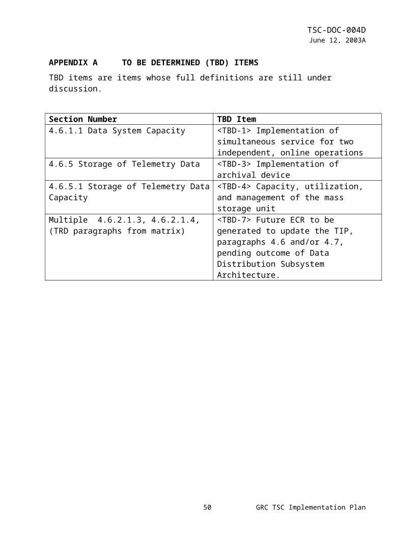
TSC-DOC-004DJune 12, 2003
TRD Paragraph TIP Paragraphconsisting of:a) One video source-destination for the video conference to/from
the NASA videoconferencing networkb) Ten video simultaneous source-destinations for the
videoconference to/from remote sites [Phase 1: Destinations accessible by standard telephone lines will be supported. Other NASA teleconferencing capabilities shall be used with TSC capabilities to support multiple destinations.]4.5.1.2 Conferencing Internal Source-DestinationThe conferencing system shall interface with the existing video and audio systems and the conference rooms for its internal destinations and sources. [Phase 1: The conferencing system shall interface with the existing GRC telephone system and the TSC conference room for its internal destinations and sources.]
4.5.1 Conferencing System CapacityThe existing conference room teleconferencing package will be used with the existing connection into the TSC video matrix. The video matrix provides a graphical control display and also allows the conference room teleconferencing package to be used as an audio destination for the video matrix. NASA (agency) and GRC teleconferencing capabilities will be used to allow the conference system to connect to more than one destination at a time.
4.5.2 Conferencing Availability/Restorability4.5.2.1 Conferencing System RestorabilityThe conferencing system shall have a MaxTTR the same or better than the overall TSC requirement for operations-noncritical services specified in 4.1.2.2.
4.5.2 Conferencing System Availability/RestorabilityTo meet the availability/restorability requirement specified in the TSC Requirements Document, the existing maintenance coverage of the teleconferencing hardware will be continued.
4.5.2.2 Conferencing AvailabilityThe conferencing system shall have an availability of 0.90 or better. [Phase 1: Not a requirement]
4.5.2 Conferencing System Availability/Restorability(see below)
4.6.1 Data System 4.6.1 Overall Data System Requirements4.6.1.1 Data System CapacityThe TSC data system shall have the capacity to simultaneously supply services to
4.6.1.1 Data System CapacityThe TSC will provide simultaneous service for 2 independent, online operations (real-time operations, simulations, or training).
52 GRC TSC Implementation Plan

TSC-DOC-004DJune 12, 2003
TRD Paragraph TIP Paragrapha) Two independent, simultaneous, online operations b) Eighty onsite users per operation (160 onsite users total)
[Phase 1: 35 onsite users per operation (70 users total) shall be supported.]
c) Fifty-five simultaneous onsite users per operation (110 total onsite users) [Phase 1: 35 simultaneous onsite users per operation (70 users total) shall be supported.]
d) Thirty remote users at 15 sties per operation (60 remote users at 30 sites total) [Phase 1: Not a requirement.]
e) Fifteen offline operations area users at 5 sitesf) Software testing and validation independent of other
operations.
for a maximum of 70 potential users (35 per operation) , and, at any given time, a maximum of 70 simultaneous users (35 per operation) . Implementation of the simultaneous service is TBD <TBD-1>.
4.6.1.2 Data System User InterfaceThe TSC shall meet requirements to provide a user interface for systems designed by the TSC for the users.
4.6.1 Data System WorkstationsThe TSC will provide access to the POIC using either X-Windows software and/or a Web browser that is hosted on either the user’s ground support equipment (GSE), or TSC provided TReK workstations. TReK workstations will be provided for users located in the TSC, offline users, and remote users by the TSC. These workstations provide the following capabilities:a. Telemetry acquisitionb. Real-time telemetry requestc. Stored telemetry retrieval and processingd. Telemetry processinge. Exception monitoringf. Telemetry storage and retrievalg. Telemetry monitoring and manipulationh. Command capabilitiesi. Database capabilitiesj. Utilitiesk. Help functionsl. Access to the Payload Data Library
53 GRC TSC Implementation Plan

TSC-DOC-004DJune 12, 2003
TRD Paragraph TIP Paragraphm. Access to the Payload Planning Systemn. Application Programming Interfaceo. Autoinstall of TReK softwarep. TReK operating configurationsAdditional information concerning TReK capabilities can be found in the POIC Capabilities Document, SSP 50304.If the user desires to use user provided GSE, it will be their responsibility to obtain, integrate and test their GSE to ensure its compatibility with the POIC. A complete description of POIC capabilities is provided in the POIC Capabilities Document (SSP 50304). The POIN interfaces are described in detail in the POIC to Generic User Interface Definition Document (SSP 50305).
4.6.1.3 Data System Availability/Restorability4.6.1.3.1 Overall Data System Restorability and Availability4.6.1.3.1.1 Data System RestorabilityThe overall data system and its functions shall have a MaxTTR equal to or better than the overall TSC requirement for operations-critical services as specified in 4.1.2.2. This excludes any equipment used for GRC Office Automation System functions.
4.6.1.2 Data System Availability/RestorabilityTo meet the availability and restorability requirements specified in the TSC Requirements Document, the TSC will configure TReK workstations with an operating system and appropriate COTS products per documentation on the TReK web site. This configuration is identified as the TSC’s Baseline TReK Configuration (BTC). The TSC will assist users in configuring the working environment on their TReK workstations, including databases, per their application specific needs. It will be the user’s responsibility to guarantee the integrity of the content of their application specific software, including databases. TReK workstations will be backed up at regular intervals to ensure against system failure, per the procedures documented in the TSC Users Guide. In addition, the TSC will maintain at least two warm spare TReK workstations. Spare workstations will be configured with a BTC. Application specific software can then
54 GRC TSC Implementation Plan

TSC-DOC-004DJune 12, 2003
TRD Paragraph TIP Paragraphbe layered on top of the BTC to restore an operational TReK workstation. TReK workstations will have a MaxTTR of 2 hours during day shift, and 12 hours if failure occurs during other shifts.
The TSC will maintain a mass storage system to store telemetry data. The server will be RAID based. It will have redundant power supplies and the major components will be hot swappable. The server will be powered with a UPS. The TSC data system will have an availability of 0.95 or better, excluding end user-induced faults, and a MaxTTR equal to or better than the overall TSC requirement for operations-critical services The TSC will maintain a server on the CSD External Services LAN. This server will be used for the distribution of the science data for the payloads. The server availability and security will be dependent on CSD. The TSC will maintain regular back ups and power the server on a UPS. Workstations used exclusively for the GRC Office Automation System will have a MaxTTR of 8 day shift hours after reporting the failure. Printers are considered operations noncritical, and will have a MaxTTR of 3 hours during day shift, and next day shift if failure during other shifts.
4.6.1.3.1.2 Data System AvailabilityThe overall data system shall have an availability of 0.95 or better, excluding end user-induced faults.
4.6.1.2 Data System Availability/Restorability(see above)
4.6.1.3.2 TSC Provided Equipment4.6.1.3.2.1 Workstations RestorabilityWorkstations shall have a MaxTTR of:a) Two hours during day shift andb) Twelve hours if failure occurs during other shifts.
4.6.1.2 Data System Availability/Restorability(see above)
55 GRC TSC Implementation Plan
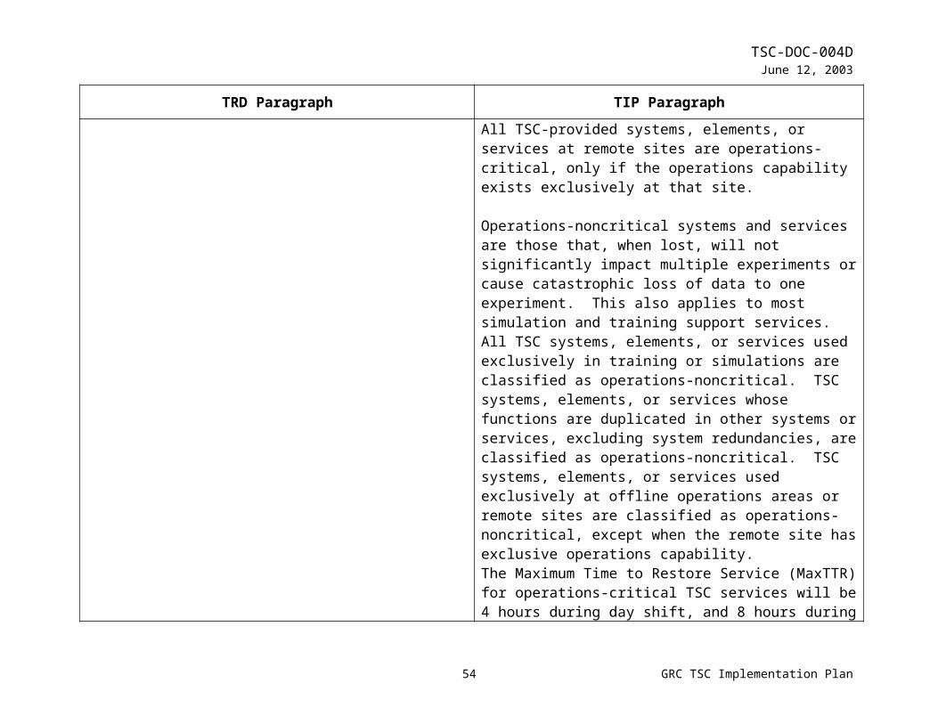
TSC-DOC-004DJune 12, 2003
TRD Paragraph TIP Paragraph4.6.1.3.3.2 Printers RestorabilityPrinters are considered operations-noncritical and redundant by implementation and have a MaxTTR of:a) Three hours during day shiftb) Next day shift if it fails during other shifts
4.6.1.2 Data System Availability/Restorability(see above)
4.6.1.4 Data System Time SynchronizationThe data system shall be synchronized to Greenwich Mean Time.
4.6 Data SystemDuring increments 2 through 6, the GRC TSC will provide access to the POIC located at Marshall Space Flight Center (MSFC). The POIC comprises three major subsystems, the Payload Data Services System (PDSS), the Payload Planning System (PPS), and the Enhanced HOSC System (EHS). PDSS acquires, stores, and distributes ISS data to the EHS, IPs, TSCs, and other payload-unique facilities. The PPS provides a set of software tools to automate planning and schedule payload activities. The EHS performs command processing and real-time and near-real-time telemetry processing for pre-launch integration and checkout, simulation training, and flight operations, which allow users to:a) Request, receive, store and process raw and processed
telemetry data,b) Modify, uplink and monitor payload commands,c) Provide access to mission services andd) Provide short-term storage of raw telemetry data.The data system, including TReK workstations, will be synchronized to Greenwich mean time, via NTP packets from the timing system. Remote TReK workstations will be handled on a case by case basis. In addition to the above capabilities, the TSC data system will also provide access to the GRC Office Automation System.All of the above functions can be performed during Increment 2 through 6 with the Telescience Resource Kit (TReK)
56 GRC TSC Implementation Plan

TSC-DOC-004DJune 12, 2003
TRD Paragraph TIP Paragraphworkstations, or equivalent user-provided Ground Support Equipment (GSE) for telemetry monitoring and commanding.
Figures 4.6-1 and 4.6-2 show block diagrams of the TSC Data System.
4.6.2 Data Requirements4.6.2.1 TelemetryThe TSC data system telemetry function shall support the following functions simultaneously per operation:a) Telemetry monitoring of payload data and experiment
caution/warning data including decommutation, conversion, calibration, limit checking, exception monitoring, and display
b) GSE packet request, generation, and distributionc) Custom data packet request, generation, and distributiond) Pseudo telemetry generation and distributione) Telemetry database creation and modification.
4.6.2 Telemetry
The TSC will provide users with TReK workstations which have the capability to acquire telemetry from PDSS and EHS. TReK workstations have the capability to ingest CCSDS packets that are transmitted from PDSS at the rate of up to 2 Mbps. TReK workstations also have the capability to ingest POIC processed telemetry as user defined Ground Support Equipment (GSE) packets and ground ancillary GSE packets. Refer to the POIC Capabilities Document for a description of the types of processed telemetry that are available to users and a description of the GSE packet request and distribution capabilities. Once telemetry has been ingested, users can store, process, and display the telemetry using a combination of MSFC developed TReK software and recommended COTS products that are installed on a TReK workstation. TReK telemetry processing software requires that the user’s CCSDS packet structures are MSFC-STD-1274 compliant, and the telemetry database definitions are MSFC-DOC-1949 compliant. For more information regarding TReK telemetry processing capabilities, refer to the POIC Capabilities Document.
4.6.2.1.1 Telemetry CapacityIn addition to the other capacity requirements of 4.6.1.1, the
4.6.2 Telemetry(see above)
57 GRC TSC Implementation Plan

TSC-DOC-004DJune 12, 2003
TRD Paragraph TIP Paragraphtelemetry function shall support an aggregate telemetry ingest rate which is determined by the HOSC to GRC TSC Data transfer rate defined in SSP 54001, Network Program Requirements Document (NPRD), Section 2736.09.02, HOSC to GRC Data Transfer Interface. This does not include X-windows, World-Wide Web, or other data services traffic. [Phase 1: each TReK workstation shall support ingest telemetry per MSFC TReK specifications.]4.6.2.1.2 Accepted Telemetry FormatsThe TSC data system shall accept, process, and display all data that: a) Meets CCSDS packet, EHS GSE packet, or EHS Custom Data
Packet formats with EHS headers per SSP 50305b) Meets MSFC-STD-1274 c) Is received from either MSFC PDSS or MSFC POIC RTDS
(EHS).
4.6.2 Telemetry(see above)
4.6.2.1.3 Telemetry DistributionThe TSC data system shall receive all user data from MSFC and redistribute the data to the requested GSE within the TSC and GSE within the GRC lab network.
<TBD-7>
4.6.2.1.4 SecurityThe TSC data system shall reside on an isolated network to protect the user’s telemetry data.
<TBD-7>
4.6.2.2 Science Data RequirementsThe TSC data system shall provide the users with a capability to help them achieve their science (processed data) requirements. The TSC data system shall provide: a) A space on the GRC External Services LAN.b) A web utility to create web pagesc) A database to allow the users to use to organize their datad)
4.6.1.2 Data System Availability/Restorability…The TSC will maintain a server on the CSD External Services LAN. This server will be used for the distribution of the science data for the payloads. The server availability and security will be dependent on CSD. The TSC will maintain regular back ups and power the server on a UPS.…
58 GRC TSC Implementation Plan

TSC-DOC-004DJune 12, 2003
TRD Paragraph TIP Paragraph4.6.2.2.1 Availability The TSC data system shall provide the users a method of transferring their data to the GRC External Services LAN from the TSC Mission Network. The availability of the GRC External Services LAN is dependent upon GRC CSD.
4.6.1.2 Data System Availability/Restorability(see above)
4.6.2.2.2 SecurityThe TSC data system will provide the users with a means to protect their science data on the TSC provided space on the GRC External Services LAN. The security of the GRC External Services LAN is provided by GRC CSD.
4.6.1.2 Data System Availability/Restorability(see above)
4.6.2.3 File Uplink/DownlinkThe TSC data system shall provide a capability per SSP 50366 HOSC to GRC TSC ICDa) To transfer files from the TSC to the MSFC POIC for file
uplinkb) Receive files from ISS via MSFC POIC GRC.
4.6.3 CommandingCommanding during Increment 2 through 6 will use an X-window type interface through an EHS machine at the MSFC HOSC.The TSC will provide users with the capability to update modifiable commands and request command uplinks via an X-windows interface to the POIC. The X-windows interface software will be provided on TSC-provided TReK workstations. Note that all user command definitions will be required to be resident in the POIC command database. In addition to command update and command uplink, command users will be able to monitor command responses via the POIC command track application, which is also an X-windows interface. Web browser software will also be provided on the TSC-provided TReK workstations to allow users access to the POIC command delog application. For more information regarding POIC command capabilities, refer to the POIC Capabilities Document.
4.6.2.4 Mass StorageThe TSC data system shall provide:
4.6.5 Storage of Telemetry DataA server class system will be available at the TSC to store raw
59 GRC TSC Implementation Plan
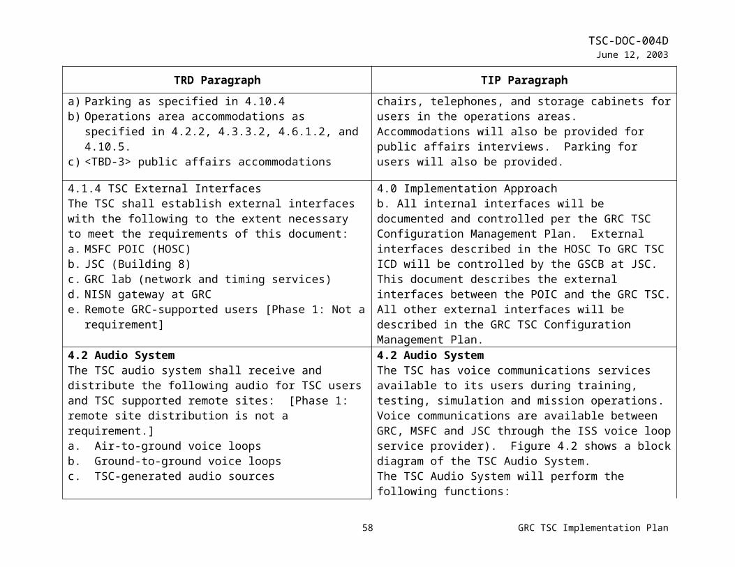
TSC-DOC-004DJune 12, 2003
TRD Paragraph TIP Paragrapha) Temporary storage of telemetry datab) Capability to retrieve the stored datac) Capability to create digital copies of stored data
telemetry. The raw data will be routed from the PDSS at MSFC to the GRC TSC using a dedicated wide area network (WAN). The TSC will then route the data to the payload developers GSE and to mass storage system. There will be two NT servers to split the load of ingesting and storing the telemetry data. The TReK software will be used to grab the packets and store them on the file servers. A minimum of 90 days of raw telemetry data will be retained before the data will be removed from the mass storage system. The TSC will not archive the telemetry data before it is deleted from the mass storage system. The payload developer will have time to create digital copies of their raw data for their own archival before the data is removed from the system.The mass storage server will have the capability to retrieve the raw telemetry data and resend it upon request to a user’s GSE. The TReK software interface will be used to request the data that is available on the mass storage server. The data will be retrieved and sent to the requested payload developer’s GSE of choice within the TSC mission network.In addition, a limited amount of telemetry data will be able to be stored locally on a TReK workstation. Refer to the TReK web site and the POIC Capabilities Document, SSP 50304, for more details.
4.6.2.4.1 Mass Storage CapacityThis function shall support:a) The same user capacity as total data system requirements for
users as specified in 4.6.1.1b) Telemetry ingest rate equal to the aggregate telemetry rate
specified in 4.6.2.1.1c) Storage for a minimum of 90 days
4.6.5 Storage of Telemetry Data(see above)
4.6.2.4.2 Mass Storage Ingest Format 4.6.2 Telemetry
60 GRC TSC Implementation Plan

TSC-DOC-004DJune 12, 2003
TRD Paragraph TIP ParagraphThis function shall accept, process, and store all data that:a) Meets CCSDS packet, EHS GSE packet, or EHS Custom Data
Packet formats with EHS headers per SSP 50366b) Meets MSFC-STD-1274 and MSFC-DOC-1949 [Phase 1: not
a requirement]c) Is received from either MSFC PDSS or MSFC RTDS
(See above)
4.6.2.4.3 Mass Storage Search and Retrieval CapabilityThe user shall be able to retrieve stored data. The users shall be able to submit a request using the TReK software and have the data resent to the specified GSE within the TSC mission network.
4.6.5 Storage of Telemetry Data(see above)
4.6.2.4.4 Mass Storage User InterfaceThe TSC shall use the TReK user interface to allow the user to access the capabilities required in 4.6.2.4.3.
4.6.5 Storage of Telemetry Data(see above)
4.6.3 CommandingThe TSC data system shall provide a capability to command payloads through the MSFC POIC per SSP 50366 HOSC To GRC TSC ICD.
4.6.3 CommandingCommanding during Increment 2 through 6 will use an X-window type interface through an EHS machine at the MSFC HOSC.The TSC will provide users with the capability to update modifiable commands and request command uplinks via an X-windows interface to the POIC. The X-windows interface software will be provided on TSC-provided TReK workstations. Note that all user command definitions will be required to be resident in the POIC command database. In addition to command update and command uplink, command users will be able to monitor command responses via the POIC command track application, which is also an X-windows interface. Web browser software will also be provided on the TSC-provided TReK workstations to allow users access to the POIC command delog application. For more information regarding POIC command capabilities, refer to the POIC Capabilities Document.
61 GRC TSC Implementation Plan

TSC-DOC-004DJune 12, 2003
TRD Paragraph TIP Paragraph4.6.3.1 Commanding CapacityThis function shall have a capacity of:a) Thirty onsite users per operation (60 onsite users total)
[Phase 1: 20 onsite users per operation (40 users total) shall be supported]
b) Fifteen simultaneous onsite users per operation. (30 total simultaneous onsite users)
c) Thirty remote users per operation (60 onsite users total) [Phase 1: Not a requirement] and
d) Fifteen simultaneous remote users per operation. (30 total simultaneous onsite users) [Phase 1: Not a requirement.
4.6.3.1 Commanding CapacityCommand capabilities at the TSC will be available for a maximum of 40 potential commanding users (20 per operation) and, at any given time, a maximum of 30 simultaneous commanding users (15 per operation).
4.6.3.2 Command Control and ManagementThe TSC shall provide the capability for facility-class payloads to control and manage remote commands by allowing a designated facility class payload command user to:a) Independently enable or disable commanding capability for a
remote site associated with that facility-class payloadb) Intercept facility-class commands from a local or remote user,
append or modify the command as necessary, and send the command on for uplink.
[Phase 1: these requirements do not apply ]
4.6.3 CommandingCommanding during Increment 2 through 6 will use an X-window type interface through an EHS machine at the MSFC HOSC.The TSC will provide users with the capability to update modifiable commands and request command uplinks via an X-windows interface to the POIC. The X-windows interface software will be provided on TSC-provided TReK workstations. Note that all user command definitions will be required to be resident in the POIC command database. In addition to command update and command uplink, command users will be able to monitor command responses via the POIC command track application, which is also an X-windows interface. Web browser software will also be provided on the TSC-provided TReK workstations to allow users access to the POIC command delog application. For more information regarding POIC command capabilities, refer to the POIC Capabilities Document.
4.6.3.3 Command Database ManagementThe TSC shall provide the capability for facility-class payloads to
4.6.3 Commanding(see above)
62 GRC TSC Implementation Plan
TSC-DOC-004DJune 12, 2003
TRD Paragraph TIP Paragraphmanage the command databases at the TSC as follows:a) Allow a unique subset of issuable commands to be identified
for each local or remote siteb) Set limits on commands unique to each local or remote sitec) Change allowable commands and limits on commands in near
real-time4.6.3.4 Command ResponsesThe TSC data system shall provide a capability to receive and display command responses to the extent allowed by SSP 50366, HOSC To GRC TSC ICD.
4.6.3 Commanding(see above)
4.6.3.5 Hazardous CommandsAll hazardous commands shall be resident in the HOSC database. The TSC database shall not contain any Hazardous commands.
4.6.3 Commanding(see above)
4.6.4 Service Requirements4.6.4.1 GRC ServicesThe TSC shall provide means to access the GRC Office Automation System
4.6 Data System (see above)
4.6.4.1.1 Restorability Workstations that are used exclusively for GRC Office Automation System are operations-noncritical and have a MaxTTR of 8 day shift hours after reporting failure.
4.6.1.2 Data System Availability/RestorabilityTo meet the availability and restorability requirements specified in the TSC Requirements Document, the TSC will configure TReK workstations with an operating system and appropriate COTS products per documentation on the TReK web site. This configuration is identified as the TSC’s Baseline TReK Configuration (BTC). The TSC will assist users in configuring the working environment on their TreK workstations, including databases, per their application specific needs. It will be the user’s responsibility to guarantee the integrity of the content of their application specific software, including databases. TReK workstations will be backed up at regular intervals to ensure against system failure, per the procedures documented in the TSC Users Guide. in addition, the TSC will maintain at least two
63 GRC TSC Implementation Plan

TSC-DOC-004DJune 12, 2003
TRD Paragraph TIP Paragraphwarm spare TReK workstations. Spare workstations will be configured with a BTC. Application specific software can then be layered on top of the BTC to restore an operational TReK workstation. . TReK workstations will have a MaxTTR of 2 hours during day shift, and 12 hours if failure occurs during other shifts.
The TSC will maintain a mass storage system to store telemetry data. The server will be RAID based. It will have redundant power supplies and the major components will be hot swappable. The server will be powered with a UPS. The TSC data system will have an availability of 0.95 or better, excluding end user-induced faults, and a MaxTTR equal to or better than the overall TSC requirement for operations-critical services The TSC will maintain a server on the CSD External Services LAN. This server will be used for the distribution of the science data for the payloads. The server availability and security will be dependent on CSD. The TSC will maintain regular back ups and power the server on a UPS. Workstations used exclusively for the GRC Office Automation System will have a MaxTTR of 8 day shift hours after reporting the failure. Printers are considered operations noncritical, and will have a MaxTTR of 3 hours during day shift, and next day shift if failure during other shifts.
4.6.4.2 ISS Mission ServicesThe TSC shall provide access to all mission services specified for users in the POIC Capabilities Document SSP 50304.
4.6.4 Mission ServicesThe TSC will provide the capability to remotely access the Payload Data Library (PDL), the Payload Information Management System (PIMS) and the Payload Planning System (PPS). PDL is an electronic ISS User Requirements Collection and Management System that is used to collect and summarize user requirements. PIMS is an electronic information system that
64 GRC TSC Implementation Plan

TSC-DOC-004DJune 12, 2003
TRD Paragraph TIP Paragraphis used by payload users to prepare for and/or re-plan increment execution. PIMS capabilities are available through a web interface. PPS is an integrated set of hardware and software used to develop payload operations plans to support the execution of onboard payload operations. Access to these system services can be obtained by using software installed on TReK workstations. Refer to the POIC Capabilities Document, SSP 50304, for more detailed information about the function and use of these tools.
4.6.5 Data System ToolsThe data system shall provide tools for the following functions:a) Database managementb) Centralized system control and monitoringc) System trend analysis d) Auditinge) Software license managementf) Word processingg) Spreadsheetsh) E-maili) Pixmap editorj) Remote logink) File transferl) Process managementm) Resource monitoringn) Databased storage of user-generated data elementso) Validation of user-generated data elementsp) TReK softwareq) Software Configuration tool
4.6 Data Systems(see above)
4.7 Networking SystemThe TSC networking system comprises all the internal LANs that
(not applicable)
65 GRC TSC Implementation Plan

TSC-DOC-004DJune 12, 2003
TRD Paragraph TIP Paragraphinterconnect the TSC data system and provide external access to the GRC lab network or other networks (through the telecommunications system).4.7.1 Networking System ConnectivityThe TSC networking system shall provide interconnectivity between the TSC data system elements, operations workstations, and administrative workstations to the GRC lab (campus) network, dedicated operations WANs, and the internet.
4.7 Networking SystemThe TSC Networking System comprises all the internal LANs that interconnect the TSC Data System and customer-provided operations ground support equipment, all TSC-hosted subnets of GRC Lab network, and a TSC-owned, but GRC lab maintained, firewall for its operations networks. Access to other networks external to GRC is through the Telecommunications System. The network system is compromised of two major networks, the TSC operations network and the GRC lab network (select subnets managed by the TSC). The separation is required to maintain lab and TSC operations network security.The TSC operations network will transmit and receive signals to and from the MSFC POIC EHS system over Wide Area Networks (WANs), through the Telecommunications System to the ISS telecommunications service provider. It will comprise the following elements:a) Router/switch with a 40 Gbps throughput capacityb) Fast Ethernet Switch, providing 10/100 Base-T with Virtual
Local Area Network (VLAN) technologyc) One hundred Fast Ethernet point to point connections at 100
Mbpsd) Remote Fast Ethernet Switch providing VLAN technology to
work station groups (TReK)e) Network management platform equipped with HP OpenView
and CiscoWorks for total network monitoringf) A separate firewall designed, implemented, and maintained
by the GRC lab services responsible for the main lab network firewall
66 GRC TSC Implementation Plan

TSC-DOC-004DJune 12, 2003
TRD Paragraph TIP Paragraph
The TSC subnets of the GRC lab network are distributed on 10 Base-T concentrators within the TSC. The common element of both networks is the Category 5 compliant twisted-pair cable infrastructure and patch panel.
4.7.2 Networking System IsolationThe networking system shall be capable of providing isolation, where required, among:a) Remote sites b) Remote sites and MSFC POIC c) Remote sites and GRC labd) GRC lab and MSFC POIC.[Phase 1: The networking system shall be capable of providing isolation between GRC lab and MSFC POIC.]
4.7.3 Network IsolationThe subnets of the GRC lab network and the TSC operations network will be physically isolated. Limited inter-network connectivity will be allowed between the GRC lab network firewall and the TSC operations network firewall. This inter-network communication will be jointly controlled by the TSC and GRC lab network services.
4.7.3 Networking System CapacityThe networking system shall provide up to 450 ports [Phase 1: 100 ports] of 100 Mbps traffic capability to individual users.
4.7.1 Network System CapacityA scalable networking architecture will be deployed to meet the port requirements specified in the TSC Requirements Document. Each of the 100 individual 100Mbps network connections on the TSC operations network will be interfaced into a group of Fast Ethernet switches and be organized into VLANs. These VLANs will be tied together in a OSI Layer 3 Backbone router/switch which will provide an aggregate throughput of 40Gbps. Ports for the subnets of the GRC lab network will be provided on 10 Base-T concentrator cards in a multiple card hub.
4.7.4 Networking System Availability and Restorability4.7.4.1 Networking System RestorabilityThe portions of the TSC networking system dedicated to operations communications shall have a MaxTTR equal to or better than the overall TSC requirement for operations-critical
4.7.2 Network System Availability/RestorabilityTo meet the availability and reliability requirements for the TSC operations network specified in the TSC Requirements Document, both routers will be dual-homed to external networks.
67 GRC TSC Implementation Plan
TSC-DOC-004DJune 12, 2003
TRD Paragraph TIP Paragraphservices as specified in 4.1.2.2. The portions of the TSC networking system not dedicated to operations communications shall have a MaxTTR equal to or better than the overall TSC requirement for operations-noncritical services as specified in 4.1.2.3.
Both routers will also contain redundant processors, network interface boards and power supplies. Flexible VLAN technology will be used to provide simultaneous network connections for real-time mission operations, simulations and development. COTS software products will be used to perform real-time network management and monitoring. The TSC network system will have an availability of 0.98 or better, and a MaxTTR equal to or better than the overall TSC requirement for operations-critical services.
To meet the availability and reliability requirement for the TSC-hosted subnets of the GRC lab network specified in the TSC Requirements Document, spares for concentrator cards and separate hubs will be maintained on-site. The TSC network system will have a MaxTTR equal to or better than the overall TSC requirement for operations-noncritical services.
4.7.4.2 Networking System AvailabilityThe portions of the TSC networking system dedicated to operations communications shall have an availability of 0.98 or better.
4.7.2 Network System Availability/Restorability(see above)
4.8 Timing systemThe TSC Timing system shall: a. Accept GMTb. Derive other required real and simulated times, including local
time, mission elapsed time, and ISS referenced timesc. Provide video display of times to TSC video systems specified
in Section 4.3.2.1d. Provide GMT to other TSC systems as required
4.8 Timing SystemThe TSC Timing System is synchronized to a timing signal that originates from the Global Positioning System (GPS). The GPS is a worldwide navigational and timing satellite system. GPS signals are received at GRC through a satellite ground terminal and distributed throughout the center via an internal cable plant in the IRIG-B format. At the TSC, the IRIG-B signal is available for redistribution, if required, but Network Timing Protocol (NTP) packets are the primary output. NTP packets are generated and distributed over the TSC Network System for use
68 GRC TSC Implementation Plan
TSC-DOC-004DJune 12, 2003
TRD Paragraph TIP Paragraphby the TSC Data, Network, and Ground Track Systems and user-provided ground support equipment. Video displays in all mission operations areas show both Greenwich Mean Time and ISS on-board time in days, hours, minutes, and seconds. Figure 4.8 shows a block diagram of the TSC Timing System.
4.8.1 Timing System CapacityThe timing system shall provide a capability to generate and display two independent sets of timing displays.
4.8.1 Timing System CapacityTwo independent sets of timing displays will be provided to the users. Room displays will show the real-time operation in progress. Simulation time displays will be available on audio-video station monitors. ISS referenced times will also be provided to users at remote sites.
4.8.2 Timing System Availability and Restorability4.8.2.1 Timing System RestorabilityThe portions of the timing system that distribute GMT to other TSC systems and TSC users shall have MaxTTR equal to or better than the overall TSC requirement for operations-critical services as specified in 4.1.2.2. All other portions of the timing system shall have a MaxTTR equal to or better than the overall TSC requirements for operations-noncritical services as specified in 4.1.2.3.
4.8.2 Timing System Availability/RestorabilityThe TSC timing system will meet the availability and restorability requirements of the TSC Requirements Document by using two separate PCs. The PC’s will generate the displays and be servers for NTP packet requests. Systems depending on NTP packets will be able to select both servers and therefore automatically fail over to the other server. A spare PC will be available on site. The portions of the timing system that create and distribute NTP packets to other TSC systems and TSC users will have a MaxTTR equal to or better than the overall TSC requirement for operations-critical services. All other portions of the TSC timing system will have a MaxTTR equal to or better than the overall TSC requirement for operations-noncritical services.
4.8.2.2 Timing System AvailabilityThe portions of the timing system that distribute GMT to other
4.8.2 Timing system Availability/Restorability(see above)
69 GRC TSC Implementation Plan

TSC-DOC-004DJune 12, 2003
TRD Paragraph TIP ParagraphTSC systems shall have an availability of 0.95 or better.4.8.2.3 Timing System Remote UsersThe TSC shall provide a display of ISS referenced times to remote sites. These functions may be incorporated into elements of other systems or services provided by other ISS service providers. [Phase 1: Not a requirement.]
4.8.1 Timing System CapacityTwo independent sets of timing displays will be provided to the users. Room displays will show the real-time operation in progress. Simulation time displays will be available on audio-video station monitors. ISS referenced times will also be provided to users at remote sites.
4.8.2.3.1 Timing System Remote Users CapacityThe timing system functions supplied to remote users shall meet the capacity requirements of 4.1.1.
4.8.1 Timing System Capacity(see above)
4.9 Ground Track SystemThe TSC Ground Track system shall: a. Provide a display of TDRS AOS/LOS times that differentiates
between S and Ku bands, and accounts for vehicle blockages and communication link availability
b. Provide a graphical depiction of vehicle on orbitc. Provide a display to the TSC video system as specified in
Section 4.3.2.1
4.9 Ground Track SystemThe TSC Ground Track System will provide a display of TDRS AOS/LOS times and a graphical depiction of vehicle on orbit, and distribute these displays to all users in the TSC. The TSC Ground Track System uses primary and secondary displays. The primary display is generated by a Unix-based system that is used by the MSFC POIC and JSC MCC, which incorporates a real-time data feed. Hardware for the JSC/MSFC system will be purchased per JSC/MSFC specifications. NASA-developed software will be provided by JSC and MSFC. COTS software will be purchased by GRC TSC. Any other required COTS products will be purchased by GRC TSC. The secondary display is a PC-based system and will be maintained for a back-up and simulation capability. The PC hardware will be updated for Year 2000 compliance. Software will be obtained through the author’s web site. The displays will be available at every TSC audio-video station and will be selectable at other video destinations through the TSC video matrix. Timing signals will be provided by the TSC timing system.Figure 4.9 shows a block diagram of the TSC Ground Track
70 GRC TSC Implementation Plan
TSC-DOC-004DJune 12, 2003
TRD Paragraph TIP ParagraphSystem.
4.9.1 Ground Track System CapacityThe TSC Ground Track system shall provide the capability to provide and distribute two independent ground track displays.
4.9.1 Ground Track System CapacityTwo independent sets of ground track displays will be available to the user. A display of TDRS AOS/LOS times and a graphical depiction of vehicle on orbit will be provided to remote sites.
4.9.2 Ground Track System Availability and Restorability4.9.2.1 Ground Track System RestorabilityThe ground track system shall have a MaxTTR equal to or better than the requirement for the overall TSC operations-noncritical services as specified in 4.1.2.3.
4.9.2 Ground Track System Availability/RestorabilityThe TSC Ground Track System will have an availability of 0.90 or better, and a MaxTTR equal to or better than the requirement for overall TSC operations-noncritical services..
4.9.2.2 Ground Track System AvailabilityThe ground track system shall have an availability of 0.90 or better.
4.9.2 Ground Track System Availability/Restorability(see above)
4.9.2.3 Ground Track System Remote UsersThe TSC shall provide a display of TDRS AOS/LOS times and a graphical depiction of vehicle on orbit to remote sites.
4.9.1 Ground Track System CapacityTwo independent sets of ground track displays will be available to the user. A display of TDRS AOS/LOS times and a graphical depiction of vehicle on orbit will be provided to remote sites.
4.9.2.3.1 Timing System Remote Users CapacityThe ground track system functions supplied to remote users shall meet the capacity requirements of 4.1.1.
4.9.1 Ground Track System Capacity(see above)
4.10 Facility RequirementsThe TSC shall provide area and minimal furniture complements to support users for operations, simulations, training, and other related activities at the TSC.
4.10.1 Facility OverviewFor Increment 2 through 6, the TSC will occupy the existing facilities in the north wing of Building 333.The main operations room, the secondary operations room, and the operations control room will be capable of providing two concurrent operations and a training activity. Other areas include an initial TReK staging area, an equipment room, videoconferencing/replanning room, a critical spares storage/technician repair area, a document library, and a HVAC
71 GRC TSC Implementation Plan
TSC-DOC-004DJune 12, 2003
TRD Paragraph TIP Paragrapharea. Heating, ventilation, and air conditioning (HVAC) and electrical power services will be provided to all areas. Electrical power services will be single-fault tolerant or use multiple sources when supporting operations-critical areas.The following areas are provided by the TSC for its users, staff, and equipment:a) Room 150 and 102/104 are operations areas for 24x7 science
activities [4000 square feet]. These rooms also provide the location for initial (Phase 1) training [1000 square feet], and printer, scanner, copier and fax supplies used for general purpose office functions that are required for users on console [100 square feet]
b) Room 153 is the operations control area for the 24x7 TSC Operations Support Group staff [300 square feet]
c) Room 151 is the communications interface and data system server area [1300 square feet]
d) Room 155 provides an area for the TSC staff to perform data system related tasks, such as data system development and validation, system administration, and workstation staging [250 square feet]
e) Room 108 is a conference room designated to provide an area for videoconferencing , replanning, and a shift hand-over function for activities that need to happen off-console [500 square feet]
f) Building 333 Annex provides storage for spares and equipment for spared system elements and modules that are not kept powered up [500 square feet]
g) Room 203 provides storage for configuration managed copies of TSC and ISS documents and drawings to be maintained [50 square feet]
h) Vending machine area
72 GRC TSC Implementation Plan
TSC-DOC-004DJune 12, 2003
TRD Paragraph TIP Paragraphi) Observation/visitors area sufficient for 25 people at a time to
view the operations in progress without disturbing the participants
j) a TSC staff office and administrative area for 15 persons [1000 square feet]
4.10.1 Facility CapacityThe TSC shall support the requirements of 4.1.1 as follows:a) Operations area(s) of 10,000 square feetb) Operation control area of 300 square feetc) Training area of 1000 square feet d) Communications interface and data system server area of 1300
square feete) ViTS conference room (25 users) of 500 square feetf) Replanning conference room (15 users) of 300 square feetg) Data system
development/validation/system-administration/workstation-staging area of 400 square feet
h) Technician repair, check-out, equipment staging area of 600 square feet
i) Spares and equipment storage area of 500 square feetj) Document and drawing storage area of 100 square feet k) Canteen/break and shift hand-over area (20 users) of 400
square feetl) Printer, scanner, copier, fax and administrative supplies area of
100 square feet,m) TSC staff office/administrative areas of 1000 square feetn) Observation/visitors area sufficient for 25 people at a time
[Phase 1: The TSC shall support the requirements of 4.1.1 as follows:
4.10.1 Facility Overview(see above)4.10.3 Facility User AccommodationsThe TSC will provide operations area accommodations, such as consoles or tables, chairs, telephones, and storage cabinets for users in the operations areas. Accommodations will also be provided for public affairs interviews. Parking for users will also be provided.
73 GRC TSC Implementation Plan

TSC-DOC-004DJune 12, 2003
TRD Paragraph TIP Paragrapha) Operations area(s) of 4000 square feetb) Operation control area of 300 square feetc) Operations areas shall be used for initial training d) Communications interface and data system server area of 650
square feete) ViTS conference room (25 users) of 500 square feetf) Replanning conference room function combined with ViTS
conference roomg) Data system
development/validation/system-administration/workstation-staging area of 250 square feet with workstation staging done in place in operations areas
h) Technician repair, check-out, equipment staging area of 200 square feet
i) Spares and equipment storage area of 300 square feetj) Document and drawing storage area of 50 square feet k) Canteen/break and shift hand-over area not provided)l) Printer, scanner, copier, fax, and administrative area –
combined with operations areas and operation control aream) TSC staff office/administrative areas of 1000 square feetn) Observation/visitors area sufficient for 25 people at a time; use
of remote video and the GRC Visitor’s Center shall be acceptable.]
4.10.2 Facility Heating, Ventilation, and Air Conditioninga. The TSC shall provide heating, ventilation, and air
conditioning (HVAC) to all areasb. Areas supporting operations-critical services shall have
sources that are single-fault tolerant or use multiple sources. [Phase 1: Not a requirement.]
c. Distribution systems need not be single-fault tolerant and can be shared if multiple sources are used. [Phase 1: Not a
4.10.1 Facility Overview(see above)
74 GRC TSC Implementation Plan

TSC-DOC-004DJune 12, 2003
TRD Paragraph TIP Paragraphrequirement.]
4.10.3 Facility Electrical Powera. The TSC shall provide electrical power to all areasb. Areas supporting operations-critical services shall have
sources that are single-fault tolerant or use multiple sourcesc. Distribution systems need not be single-fault tolerant and can
be shared if multiple sources are used
4.10.1 Facility Overview(see above)
4.10.4 Facility ParkingThe TSC shall provide parking for the number of users specified in 4.1.1.
4.10.3 Facility User AccommodationsThe TSC will provide operations area accommodations, such as consoles or tables, chairs, telephones, and storage cabinets for users in the operations areas. Accommodations will also be provided for public affairs interviews. Parking for users will also be provided.
4.10.5 Operations Area AccommodationsThe TSC shall provide accommodations, such as consoles or tables, chairs, telephones, storage cabinets, for its users in the operations areas.
4.10.3 Facility User Accommodations(see above)
4.11 Operations SupportThis section describes the types of support that the TSC shall be required to provide.
(not applicable)
4.11.1 Operations Support at the TSC4.11.1.1 Pre-Increment Support at TSCThe TSC shall provide engineering and technical support for experiment pre-increment operations including simulations, ground support personnel training, pre-increment development on TSC-furnished equipment, and set-up, test, validation, and certification of all ground support equipment for experiment teams at the TSC. These activities shall be supported during day shift. Continuous support for simulations shall be provided when required.
4.11.2 TSC Pre-Increment Operations ActivitiesDuring requirements definition, users submit a mission request for to the TSC project manager no later than I-24. Detailed user requirements are collected through the PDL in the following manner: real-time and voice requirements at I-23, EHS/POIC requirements at I-15, and TSC specific requirements at I-10.. Users participate in periodic Telescience Working Group Meetings to clarify user requirements.
75 GRC TSC Implementation Plan
TSC-DOC-004DJune 12, 2003
TRD Paragraph TIP ParagraphDuring Increment 2 through 6, users will submit their ground operations requirements through MSFC using the Payload Data Library (PDL). PDL submittals will be via paper input rather than electronic means.
During preliminary assessment, the TSC staff performs an assessment study of the user requirements. Increment specific documents are developed, which, when complete, identify new system requirements. These documents are reviewed and agreed to by the user.During resource allocation, the TSC staff performs a detailed study of space allocations (including user and TSC staff work areas), equipment allocations (including TReK workstations, printers, and audio/video stations), common services, and new equipment considerations.
During increment system design and procurement, a system design is developed to include new and existing equipment, and detailed drawings of this design are developed. When the design is completed, procurement begins for new equipment purchases.
During system preparation, user work areas are prepared with TSC provided equipment and Ground Support Equipment (GSE). Interface and system verification activities are performed, operation procedures are developed, and security assignments are issued and activated.During personnel training, the TSC provides staff and user training on the Audio and Video Systems, TReK workstations, common services equipment, and increment specific equipment, procedures, and services.
76 GRC TSC Implementation Plan
TSC-DOC-004DJune 12, 2003
TRD Paragraph TIP ParagraphSimulations begin at I-10 months. The simulations identified are listed below:
1 Cadre/PD Team Operations/Interfaces/Products Simulation2 Integrated Payload Only Simulation3 US/PCC/PD/Crew Simulation4 Joint Multi-Segment Training Simulation
During operational certification, the TSC staff and users are certified prior to increment support per the Payload Ground Support Personnel Training and Certification Plan. The TSC will hold an Operational Readiness Review (ORR) prior to each increment.
4.11.1.2 Increment Support at TSCThe TSC shall support experiment increment operations on a continuous basis for experiment teams at the TSC when required by the experiment teams.
4.11.3 TSC Increment Operations ActivitiesIncrement operations begin when user experiments are powered up, or per special user requirements. Increment operations end when user experiments are completed, or per special user requirements. Increment operations can be separated into three categories: operations start-up, nominal operations, and off-nominal operations.
Operations start-up will begin after the interfaces and systems are tested and found to be operationally ready. The TOC and technician go through the operations start-up check list to power up all TSC systems and activate all facility services.During nominal operations, the TSC will be operational 24 hours per day, based on user requirements. TSC staffing during this period will consist of an Operations Support Group (OSG) and an Engineering and Technical Support Group (ESTG). TSC users
77 GRC TSC Implementation Plan
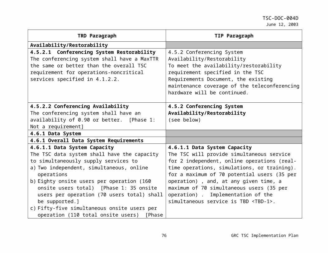
TSC-DOC-004DJune 12, 2003
TRD Paragraph TIP Paragraphinterface with the TOC to request support or report anomalies during increment operations.
During off-nominal operations, the TOC and technician will assess the severity of the problem or anomaly, assign a criticality level, and determine a course of action. ETSG personnel will be available during off hours on a call-in basis to work off-nominal operations.
4.11.1.3 Post-Increment Support at TSCThe TSC shall support experiment post-increment operations at the TSC during day shift.
4.11.4 TSC Post-Increment Operations ActivitiesDuring post-increment operations, TSC deactivation activities occur, per user requirements. The TSC staff and the users hold a debriefing shortly after deactivation. Users remove their GSE within 10 working days. The TSC will retain stored user data for 30 calendar days. TSC technicians begin to reconfigure work areas for the next increment.
4.11.2 Operations Support for Remote Sites4.11.2.1 Pre-Increment Support for Remote SitesThe TSC shall provide engineering and technical support for experiment pre-increment operations including simulations, ground support personnel training, pre-increment development on TSC-furnished equipment, and set-up, test, validation, and certification of all ground support equipment. The initial support shall be provided by TSC staff at the remote site during the initial set-up. Latter support shall be provided from the TSC (not at the remote site) during day shift. Continuous support from the TSC (not at the remote site) for simulations shall be provided when required. [Phase 1: the TSC shall provide minimal advice to remote sites. Set-up, training, testing, validation, and certification shall be the responsibility of MSFC.]
4.11.1 TSC Operations ApproachThe TSC Operations Approach will provide services for local TSC and remote site ISS experimenters. Support for pre-increment, increment, and post-increment activities will vary, depending on whether the user is located at the TSC, offline, or at a remote location. The following lists the support provided for each operational phase, per location:a) Pre-increment support
1) At the TSC, engineering and technical staff will be provided for simulations, ground support personnel training, pre-increment development on TSC-furnished equipment, and set-up, test, validation, and certification of all GSE for experiment teams at the TSC.
78 GRC TSC Implementation Plan
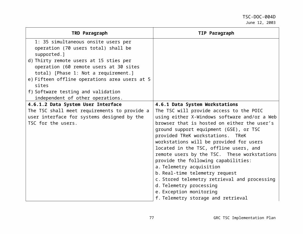
TSC-DOC-004DJune 12, 2003
TRD Paragraph TIP Paragraph2) At offline locations, the same support is provided as at the
TSC, but the TSC staff will be at the offline site during initial set-up. Other activities will be supported from the TSC.
3) At remote locations, the TSC staff will provide minimal advice. Set-up, training, testing, validation, and certification are the responsibility of MSFC.
b) Increment support1) At the TSC, support will be provided on a continuous
basis.2) At offline locations, support will be provided from the
TSC (not at the offline site)3) At remote locations, the TSC staff will provide minimal
advice. Other required services will be provided by MSFC.
c) Post-increment support1) At the TSC, support will be provided during the day shift.2) At offline locations, support will come from the TSC (not
at the offline site) during the day shift.3) At remote locations, support will be provided during the
day shift.
4.11.2.2 Increment Support for Remote SitesThe TSC shall provide support from the TSC (not at the remote site) experiment increment operations on a continuous basis when required by GRC experiment users. [Phase 1: The TSC shall provide minimal advice for remote sites. Other required services shall be provided by MSFC.]
4.11.1 TSC Operations Approach(see above)
4.11.2.3 Post-Increment Support for Remote SitesThe TSC shall support experiment post-increment operations during day shift.
4.11.1 TSC Operations Approach(see above)
79 GRC TSC Implementation Plan
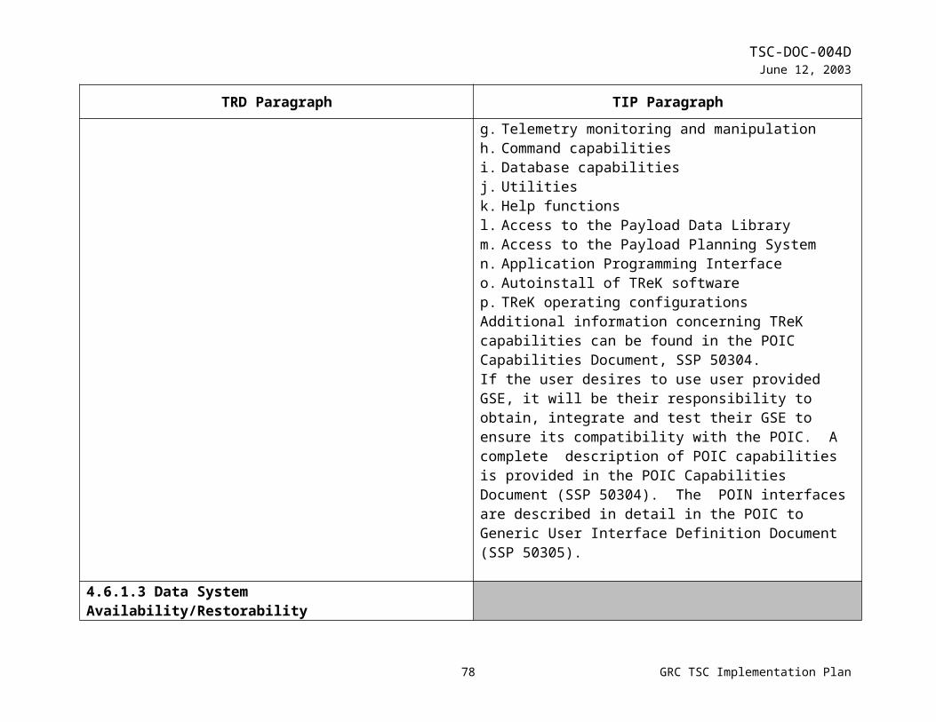
TSC-DOC-004DJune 12, 2003
TRD Paragraph TIP Paragraph4.11.3 Operations Support for Offline Operations Areas4.11.3.1 Pre-Increment Support for Offline Operations AreasThe TSC shall provide engineering and technical support for experiment pre-increment operations including simulations, ground support personnel training, pre-increment development on TSC-furnished equipment, and set-up, test, validation, and certification of all ground support equipment. The initial support shall be provided by TSC staff at the offline operations area during the initial set-up. Latter support shall be provided from the TSC (not at the offline operations area) during day shift. Continuous support from the TSC (not at the offline operations areas) for simulations shall be provided when required.
4.11.1 TSC Operations Approach(see above)
4.11.3.2 Increment Support for Offline Operations AreasThe TSC shall provide support from the TSC (not at the remote site) experiment increment operations on a continuous basis when required by GRC experiment users.
4.11.1 TSC Operations Approach(see above)
4.11.3.3 Post-Increment Support for Offline Operations AreasThe TSC shall support experiment post-increment operations during day shift.
4.11.1 TSC Operations Approach(see above)
4.12 SecurityThe TSC shall implement a security program that is consistent with the NASA mission and National Policy. The following requirements derived from NASA Security Program NMI 1600.2 are applicable to the TSC: a) The TSC shall protect resources against loss, theft, vandalism,
espionage, sabotage, and other threats or acts of violence via access controls.
b) The TSC shall provide appropriate and adequate protection for facilities, property, and information in its possession or custody.
c) The TSC shall, in conjunction with the GRC security office,
4.12 Security Assessment ProcessThe security program at the TSC is a rule-based, risk management process. The TSC security approach uses, virtual LAN’s, a firewall (with access list, auditing software tools), and management controls to form an integrated approach to security. The TSC will have procedures, acceptable rules and plans to insure the protection of proprietary information and the preservation of TSC services. These plans are the Facility Security Operations Plan, Computer Security Plan, Emergency and Contingency Plan, COMSEC Security Plan. General site security procedures, acceptable site security rules, and physical security information for use during Space Station increments will
80 GRC TSC Implementation Plan

TSC-DOC-004DJune 12, 2003
TRD Paragraph TIP Paragraphapply appropriate levels of communications security (COMSEC) to NASA telecommunications systems.
d) The TSC shall, in conjunction with the GRC security office, ensure that only those employees with a clear and demonstrated need are granted a security clearance.
e) The TSC shall, in conjunction with the GRC security office, employ a security logging, reporting and alerting system.
f) The TSC shall, in conjunction with the GRC security office, provide a security education and awareness training.
g) The TSC shall be designated as a nonclassified site. All Classified controls and procedures shall be the responsibility of the owner who brings classified material into the facility.
reside in the ISS Operations Guide. Computer security, incident response policies and procedures will be incorporated into both TReK server and workstation data files. A downloaded hardcopy from the server will act as backup in case access is denied. A security specification document will be prepared if this event occurs. GRC TSC will be responsible for the security certification at remote sites. Figure 4.12 shows a block diagram of TSC Security Risk Management.
4.13 Training and Certification4.13.1 Ground Support Personnel TrainingThe TSC shall meet the following ground support personnel training requirements:a) Provide a certified trainer and training for all TSC users at the
TSC [Phase 1: MSFC will train TSC users on EHS applications]
b) Provide a certified trainer and training for all remote users associated with GRC experiments [Phase 1: not a requirement.]
c) Provide training for TSC staff
4.13.1 Training ProcessCertified TSC staff will provide training to all Ground Support Personnel at the TSC. User training will consist of:a) generic operations training, including training in operations
of TSC provided voice and video systems, and security, and b) increment specific training, including training in operations
that are coordinated with MSFC, JSC, and the crew.TSC staff training will consist of detailed TSC systems operation, maintenance, and anomaly resolution for all TSC facility and equipment systems.Training methods will include class room exercises, workbook exercises, computer-based training, hands-on exercises, simulations, and on-the-job training.The following training template will be followed:a) TSC to payload developer generic training will be completed
prior to the start of simulations.b) TSC staff facility training will be completed prior to the start
of simulations.
81 GRC TSC Implementation Plan

TSC-DOC-004DJune 12, 2003
TRD Paragraph TIP Paragraphc) Payload developer console operation simulations will begin at
I-10.d) Integrated Payload only simulations will begin at I-8.e) US PCC/POIC/TSC/Crew simulations will begin at I-6.f) Joint Multi-Segment Training simulations will begin at I-3.
4.13.1.1 Generic Operations TrainingThe TSC shall meet the following generic operations training requirements:a) Provide generic operations training prior to increment
simulations for the ground support personnel specified in 4.13.1
b) Provide training on all generic ISS payload-related interfaces and mission services [Phase 1: provide training on all TSC hosted systems, excluding TReK workstations.]
c) Provide the capability to conduct generic operations training simultaneous with 2 other operations (real-time and/or simulated)
d) Maintain separation between training and real-time operations
4.13.1 Training Process(see above)
4.13.1.2 Increment-Specific Operations TrainingThe TSC shall provide increment specific training as required to experiment users and TSC staff prior to certification of ground support personnel specified in 4.13.1.
4.13.1 Training Process(see above)
4.13.1.3 Simulations and On-the-Job TrainingThe TSC shall utilize simulations and on-the-job training to train experiment users and TSC staff.
4.13.1 Training Process(see above)
4.13.2 Certification4.13.2.1 Initial CertificationThe TSC shall certify that all ground support personnel at the TSC and remote sites are trained for each increment and in accordance with Payload Ground Support Personnel Training and Certification Plan
4.13.2 Certification PlanCertification for the TSC facility, staff, and users will occur during training, testing, and simulation activities. Staff and user certification will be in accordance with programmatic requirements to be defined in the Payload Ground Support
82 GRC TSC Implementation Plan
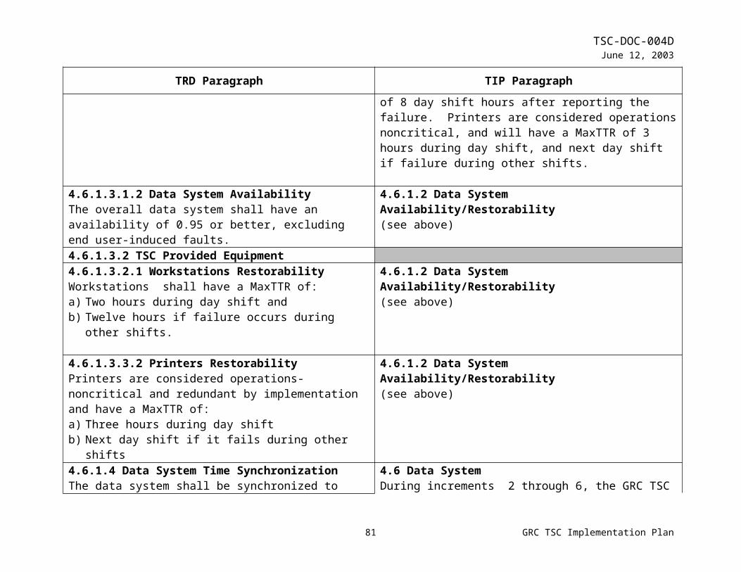
TSC-DOC-004DJune 12, 2003
TRD Paragraph TIP ParagraphPersonnel Training and Certification Plan, MSFC-PLAN-2848. All TSC staff and user training and certification will be tracked and verified per a database administered by the TSC Training Lead, per the GRC TSC Training Plan. Training not administered at the TSC will need to be verified, certified, and reported to the training lead.Ground Support Personnel must be certified prior to the beginning of each increment. All TSC facility and operational systems must be certified prior to the Operational Readiness Review (ORR).The TSC will hold an ORR prior to each increment to adhere to the Certification of Flight Readiness (CoFR) process.
Recertification of the TSC facility, staff, and users will be performed prior to each increment by reviewing requirements, and performing any additional increment specific training required.
4.13.2.2 Certification TrackingAll training performed by and for the TSC will be loaded into a database and tracked by individual names, training course, payload/experiment, and increment
4.13.2 Certification Plan(see above)
4.13.2.3 Re-certificationPersonnel will be re-certified for each increment by taking refresher courses, as necessary, and increment specific training.
4.13.2 Certification Plan(see above)
83 GRC TSC Implementation Plan