graphic1 - cole-parmer 800-451-5172 800-242-4685 (service) telex 94-0136 bio tek shvt fax...
TRANSCRIPT


EL301 Manual Update PN 3011000, Rev. C.1
The Seiko printer information in your manual has been replaced as follows: • Page 2-18, Table 2.4-1. Model EL 301 Optional Accessories: OPTIONAL PART ACCESSORIES NUMBER NOTES Citizen Printer 97128 40-column printer. Citizen Replacement Printer Paper 97129 For use with Citizen printer. Please call Bio-Tek’s Technical Assistance Center at 800-242-4685 if you have any questions.


0-1
BIO-TEK® INSTRUMENTS. INC.
MICROWELL STRIP READER
MODEL EL301
OPERATOR’S MANUAL
MANUAL PART NUMBER 3011000
REVISION C
MAY 1993
BIO-TEK INSTRUMENTS, INC.HIGHLAND PARK, BOX 998WINOOSKI, VT 05404-0998 USA802-655-4040800-451-5172800-242-4685 (SERVICE)TELEX 94-0136 BIO TEK SHVTFAX 802-655-7941

0-2
DOCUMENT REVISION RECORD
Revision, date, and section Changes
A 12/28/1989 Original version.
B 8/29/91 Lamp / Filter replacementprocedure, pages, pages 5-3through 5-9
C 5/1/93 2-3, 2-4 Updated part numbers inAccessories Lists
Bio-Tek® is a registered trademark of Bio-Tek Instruments, Inc.

0-3
TABLE OF CONTENTS
Page
0-2 DOCUMENT REVISION RECORD0-4 TABLE OF CONTENTS0-7 LIST OF FIGURES0-8 LIST OF TABLES0-9 INTRODUCTION TO THE MODEL EL301 OPERATOR’S
MANUAL
1-1 1 MODEL EL301 GENERAL INFORMATION
1-1 1.1 Summary of Features1-2 1.2 Short-Form Instructions
2-1 2 MODEL EL301 DESCRIPTION
2-1 2.1 Specifications2-2 2.2 Description and Location of Model EL301 Components
2-6 2.2.1 Front Panel
2-11 2.2.1.1 Filter Paddle2-13 2.2.1.2 Microwell Strip Carrier
2-15 2.2.2 Rear Panel2-15 2.2.3 Side Panels
2-17 2.3 Accessories2-18 2.4 Optional Accessories
3-1 3 INSTALLATION AND CONNECTION TOPERIPHERAL DEVICES
3-1 3.1 Unpacking and Inspection3-2 3.2 Electrical Connections
3-2 3.2.1 Wall Socket3-2 3.2.2 Battery Pack
3-4 3.3 Connecting the Model EL301 to a Printer3-6 3.4 Connecting the Model EL301 to an External Computer3-6 3.5 Installing Interference Filters in the Filter Paddle

0-4
TABLE OF CONTENTS (CONTINUED)
Page
4-1 4 OPERATION
4-1 4.1 Introduction4-1 4.2 Preliminary Procedures4-2 4.3 Definitions
4-2 4.3.1 Display Windows on the Model EL301
4-2 4.3.1.1 User Prompts4-3 4.3.1.2 Error Messages
4-6 4.3.2 Files
4-7 4.3.2.1 Calculation Formats Available
4-9 4.3.3 Functions Performed by the Model EL301
4-9 4.3.3.1 Blanking and Standards
4-9 4.3.3.1.1 Blanking4-11 4.3.3.1.2 Standards
4-12 4.3.3.2 Clearing4-13 4.3.3.3 Reading
4-14 4.3.3.3.1 Single Wavelength versus Dual Wavelength4-16 4.3.3.3.2 Setting Limits for Absorbance and Concentration Values
4-17 4.3.3.4 Data Reduction
4-17 4.3.3.4.1 Absorbance4-18 4.3.3.4.2 Ratio4-20 4.3.3.4.3 Linear Equation4-22 4.3.3.4.4 Difference
4-22 4.3.3.5 Data Output to Peripheral Devices
4-23 4.4 Operation
4-23 4.4.1 Power ON

0-5
TABLE OF CONTENTS (CONTINUED)
Page
4-24 4.4.2 Positioning the Microwell Strip Carrier on the BehringEL301 Guide Rail
4-24 4.4.3 Inserting the Filter Paddle into the Model EL3014-26 4.4.4 Setting Up a File: Tutorial
4-26 4.4.4.1 Power Up and Calibration4-28 4.4.4.2 File Number and Memory Location4-29 4.4.4.3 Microwell Strip Configuration and Wavelength Options
4-30 4.4.4.4 Calculation Options Setup
4-32 4.4.4.4.1 Ratio4-34 4.4.4.4.2 Linear Equation4-36 4.4.4.4.3 Difference
4-37 4.4.4.5 Limit Options Setup4-39 4.4.4.6 Data Output Options Setup
4-40 4.4.5 Reading a Microwell Strip4-44 4.4.6 Sample Printouts
5-1 5 SAFETY, MAINTENANCE, AND SHIPPING
5-1 5.1 Electrical Safety5-1 5.2 Maintenance
5-1 5.2.1 Testing the Light Bulb
5-3 5.2.1.1 Replacing the Light Bulb5-5 5.2.1.2 Recalibrating the Light Beam
5-6 5.2.2 Cleaning Exterior Surfaces5-6 5.2.3 Cleaning the Optics
5-7 5.3 Storage and Shipping5-8 5.4 Warranty
6-1 6 TROUBLESHOOTING

0-6
LIST OF FIGURES
Page
2-3 2.2-1 Front View of the Model EL301
2-12 2.2.1.1-1 Filter Paddle with Interference Filters2-14 2.2.1.2-1 Microwell Strip Carrier
2-16 2.2.2-1 Rear and Side Panel Connectors for the Model EL301
3-3 3.2-1 Model EL301 Connections3-5 3.3-1 Schematic for Pin Assignment of Model EL301 Cable
and Connector3-7 3.4-1 Serial Port Connections for the Model EL301
4-5 4.3.1-1 Display Windows Defined for the Model EL3014-8 4.3.2-1 Number of Wells Stored in Memory
4-21 4.3.3.4.3-1 Graphic Interpretation of Linear Equation
4-25 4.4.2-1 Positioning the Microwell Strip Carrier on the ModelEL301 Guide Rail
4-45 4.4.6-1 Sample Printouts
5-4 5.2.1.1-1 Light Bulb Assembly

0-7
LIST OF TABLES
Page
2-17 2.3-1 Model EL301 Accessories2-18 2.4-1 Model EL301 Optional Accessories
6-1 6-1 Troubleshooting the Model EL301

0-8
This page intentionally left blank.

0-9
INTRODUCTION TO THE MODEL EL301
OPERATOR’S MANUAL
This manual is the operator’s manual for the Model EL301 Strip Reader. It contains general informa-tion about the Model EL301, a description of its components, and instructions for its use. It doesnot contain instructions or documentation required to service the unit. If a problem develops, theuser should contact Bio-Tek. The user should never attempt to service the unit before consultingwith Bio-Tek service personnel.
The objectives of this manual are to provide:
1. sufficient information about the design of the Model EL301 to enable the user tounderstand its use (Sections 1 and 2) as well as short-form instructions (Section 1);
NOTE: The short-form instruction pages are printed on colored paper stock so thatthis section can be quickly located within the operator’s manual.
2. guidance for installing the unit and connecting to peripheral devices (Section 3);
3. procedures for operating the Model EL301 (Section 4);
4. procedures for maintaining, storing, and shipping the Model EL301 (Section 5);and
5. procedures for troubleshooting the Model EL301 (Section 6).

0-10
This page intentionally left blank.

1-1
1 MODEL EL301 GENERAL INFORMATION
1.1 Summary of Features
The Model EL301 Strip Reader is a compact, light-weight single anddual wavelength photometer designed to measure and interpret theabsorbances in microwell strip assays. The wavelength of the light usedis determined by the interchangeable filters mounted on the filterpaddles. The Model EL301 is ruggedly designed and has a black exte-rior of anodized aluminum. In addition, the unit is completely portableand can be used with an optional battery pack allowing its use at remotesites not accessible to ordinary readers. The Model EL301 is designedto be used with both hands: one hand to move the microwell stripcarrier and the other hand to enter the data (the unit rests on 4 non-skidfeet so that it will not slide around when the carrier is moved).
The design of the Model EL301 accommodates flat- or round bottom 8-well, 12-well, or 16-well (2 x 8) microstrip configurations. The stripsmust be 9 mm (0.355") from well center-to-well center. The unit isdesigned so that well positions are automatically sensed and the micro-processor can perform the user-defined operations on the well currentlyin the optical measurement channel. The internal microprocessor enablesthe user to access user-defined microwell analysis programs via the unit’skeypad. These programs enable the user to choose:
1. single or dual wavelength
2. absorbance readings, ratio, linear equation (regression),or difference (for 2 x 8 wells only) calculations.
The Model EL301 has the following features:
1. automatic well location sensing
2. user-defined analysis programs
3. automatic average blanking
4. large 2-line 16-character liquid crystal display (LCD) for userprompting and data entry

1-2
5. internal memory that stores up to 12 microplates of absorbance values (1,152absorbance wells)
6. RS-232C serial computer interface (DCE configuration)
7. parallel printer interface (Centronics-style)
8. battery or line power (supply requirements: 12 V, 0.6 amps)
9. optional: printer and cable, rechargeable battery pack, carrying case, and additionalmicrowell strip carriers
10. filter paddles with interchangeable filters.
Well locations, absorbance values, and results are displayed on the large LCD. Standards and blanksmay be carried over from strip-to-strip within each program. Data may be stored in the ModelEL301 memory, printed out, or sent to a computer for more detailed analysis.
1.2 Short-Form Instructions
For your convenience we have included new short-form instructions at the end of this section of theModel EL301 Strip Reader Operator’s Manual. The remainder of this section is devoted to theseShort Form Instructions.
Please take the time to read the manual carefully before using these Short Form Instructions tooperate the Model EL301.
NOTE: The Short Form Instructions are printed on colored stock so that they may be quickly located within the operator’s manual.

1-3
***********************************
SHORT FORM INSTRUCTIONS
***********************************
We also have a new direct toll-free line to ourService Department; please call: 1-800-242-4685(1-800-24-BIOTK)

1-4
MODEL EL301 STRIP READER
“DISPLAY” WINDOW
Memory Clear and availablefor Data Storage
Ready to Read Strip Label # of Stripbeing read; also, mem-
File # ory location of StoredData for Strip #1A.
F1 READY/MC 1A
C2 1.543 +
Well Location on Calculated Result.Strip #1A Concentration or Cut-off
indication (+, -, or +/-Optical Density or indeterminate “gray” zone).Absorbance of Well C2.
(1) The “DISPLAY” window is what the end-user will see during the process of reading astrip or series of strips.
(2) Each File (in other words: F1, F2, F3, F4) may be programmed independent of eachother. Once each File is programmed, the end-user never needs to reprogram the fileagain.
(3) Well Location of Strip being read:
8-well strips (1 x 8): A1 to H112-well strips (1 x 12): A1 to A1216-well strips (2 x 8): A1 to H1, then A2 to H2
(4) Absorbance of Strip being read:
“b” after value indicates BLANK Well (e.g., 1.543b)“s” after value indicates STANDARD Well location (e.g., 1.543s)Nothing after value indicates SAMPLE Well location (e.g., 1.543 )

1-5
“SETUP” WINDOW
The “SET-UP” Window is used ONLY for programming the Strip Reader. Once a program isdefined, it is stored in memory and does not need to be re-entered even if the Strip Reader isturned off.
TO PROGRAM THE STRIP READER:
(1) Press the DISPLAY/SETUP key once (located on the top, right of the keyboard).
(2) The “SETUP” Window will appear.
(3) To ESCAPE from the “SETUP” Window at any time, press the DISPLAY/SETUP keyonce. The “DISPLAY” Window will re-appear.
Cut-off Report (Limit report).“SETUP” Window is Yes or No indication (“Y” or “N”defined here. directly beneath “L”).
File # to bepreprogrammed.
Data to be sent outSerial port. Yesor No indication.
Data to be sent outParallel port. Yesor No indication.
F1 SETUP L S P
8 S ABSORB N N Y
Type of Stripto be read:
Type of Data Reduction8-well (1 x 8) to be performed. For example:12-well (1 x 12) Display ABSORBANCE readings only.16-well (2 x 8)
Single orDual Wavelength(“S” or “D”)

1-6
STRIP READERPROGRAMMABLE FILES AND DATA STORAGE
DEFINITION OF FILES:
(1) 4 Files are available in each Strip Reader.
(2) Each File may be independently programmed to read a series of strips, store theabsorbance values, and perform data reduction on these absorbances.
(3) Each File is labeled as F1, F2, F3, or F4. Absorbance Data are “stored” withinthe File that it is read. For example, strips read while the display shows “F1” arestored in a Memory Location area designated as F1.
Each File defines Data Reduction Programand Location of Stored Data.
F1 F2 F3 F4
Each File contains 3Plates, (A, B, C)where strips areread and datastored.
A B C
Each Plate contains 6Strips, (1, 2, 3,4, 5, or 6)where wells areread and datastored.
1 2 3 4 5 6
Each Strip contains8, 12, or16 Wells.
8 12 16

1-7
The File #, Plate Letter, and Strip # designate the strip being read and also indicate the Data Storagelocation of those absorbance values. They are always indicated on the “DISPLAY” window:
F3 READY/MC 2A
This means: Read the strip now in the carrier using the program from FILE #3. This is the 2ndstrip in Plate A. To recall or print data from this strip, the display should appear as
above.
NOTE: If the strip already contains data, the display will showW1/MF or W2/MF where W1 amd W2 are the filter wavelengthsused and MF means “Memory Full.” Press the CLEAR key toobtain the preceding “DISPLAY” window.

1-8
TO PROGRAM A FILE TO READ ABSORBANCE
After the Strip Reader has been turned on and calibrated for the filter wavelengths to be used, per-form the steps to program a File to read Absorbance.
(1) Press the DISPLAY/SETUP key once. When the “SETUP” window appears, you will notethat the CURSOR is on the 2nd line, far left. The CURSOR indicates which Parameter youwish to change within that File.
(2) Select Strip Type:Press the OPTION key until “8” F1 SETUP
appears (8-well). 8
(3) Select Wavelength:Press the PROMPT key to move the F1 SETUP
CURSOR to the next location. Use the 8 S
OPTION key until “S” appears (Single).
(4) Select Calculation Method:Press PROMPT then OPTION F1 SETUP
until “ABSORB” appears. 8 S ABSORB
(5) Cutoff or Limit Report:Press PROMPT then OPTION until “N” F1 SETUP L
appears. This means do not perform a 8 S ABSORB N
limit report on these absorbance values.
(6) Serial Output:Press PROMPT then OPTION until “N” F1 SETUP L S
appears. This means do not send data 8 S ABSORB N N
out the Serial port.
(7) Parallel Output:Press PROMPT then OPTION until F1 SETUP L S P
“Y” appears. This means send data out 8 S ABSORB N N Y
the parallel port to a printer.Make sure the Strip Reader is connectedto a printer.
(8) Press the DISPLAY/SETUPkey once to ESCAPE to the F1 READY/MC 1A
“DISPLAY” window.
You are now ready to read the absorbance values of an 8-well strip in Single wavelength and storethe data in File #1.

1-9
GETTING READY TO READ A STRIP
The “DISPLAY” window should appear as:
F1 READY/MC 1A
Choose the Strip #, Plate Letter, and File #:
(1) The CURSOR should be located under the Strip #.Use the OPTION key to progress from 1# to the next strip #.
(2) Press PROMPT to move the CURSORunderneath the Plate Letter. Use F1 READY/MC 1A
OPTION to change the Plate inwhich the Strip is located.
(3) Press PROMPT to move the CURSORunderneath the FILE #. Use F1 READY/MC 1A
OPTION to change the FILE #.
Place the Strip Carrier with an 8-well strip onto the guide rail.The Well Location should be indicated on the DISPLAY:
F1 READY/MC 1A C1 __________ __
NOTE: If the well location has been set up as a STANDARD well, the display will be:
F1 READY/MC 1A C1 ___________s___

1-10
TO READ THE STRIP:
(1) You must BLANK before reading any STANDARD and SAMPLE absorbance values.
BLANK on Air by removing the Strip Carrier and pressing the BLANK key. BLANK ona well by moving the Strip Carrier to the Well Location (indicated in the “DISPLAY”window), and pressing BLANK.
You may BLANK on as many wells as you like BEFORE reading any STANDARD wells(if used) and then reading the SAMPLE wells. BLANKS may be carried over from onestrip to the next.
(2) Move the Strip Carrier to the first SAMPLE well to be read. Press the READ key.
(3) The ABSORBANCE value will immediately appear in the “DISPLAY” window:
F1 READY/MC 1A B1 1.400
(4) Move the Strip Carrier to the next SAMPLE well to be read. Press READ.
(5) Press the DATA OUT key to print Strip 1A ABSORBANCE values.

1-11
OTHER PROGRAMS
LINEAR EQUATION
(1) Press the DISPLAY/SETUP key once to change to the “SETUP” window.
(2) Press the PROMPT key to advancethe cursor to the DATA REDUCTION F1 SETUP L S P
position (ABSORB). Press OPTION 8 S LINEQU N N N
until “LINEQU” appears.
(3) Press ENTER to enter into the subroutine.
NOTE: In this subroutine, remember that:
- PROMPT advances the CURSOR to the right duringSTANDARD CONCENTRATION selections.
- OPTION provides choices (numbers or letters).
- ENTER stores the programmed data and then advancesto the next parameter.
(4) Choose the number of STANDARDS using the OPTION key (up to 5STANDARDS), then press ENTER.
- Choose the location of the 1st STANDARD (all other STANDARDSmust follow sequentially) and then press ENTER.
NOTE: After the location of the first STANDARD is entered,CONCENTRATION UNITS (e.g., UG/ML) are selected. (This displayappears only after the first STANDARD.)
- Enter the concentrations of each standard by using the PROMPT key to advance thecursor, the OPTION key to enter numbers, and the ENTER key to advance to the nextconcentration.
(5) When all parameters have been entered, the window will return to “LINEQU” (as in thepreceding Step #2).
(6) Press the DISPLAY/SETUP key once to return to the “DISPLAY” window.

1-12
(7) BLANK as many wells as desired. BLANKS may be carried over from one strip to thenext.
NOTE: Remember that BLANK wells must be read BEFORE readingSTANDARD wells and that STANDARD wells must be read BEFOREreading SAMPLE wells.
(8) STANDARDS may be carried over from strip-to-strip, and plate-to-plate. If you arereading Strip #1 of a new plate, the “DISPLAY” window shows:
NEW STANDARDS? OPTION OR ENTER
Press ENTER if you wish to read “NEW” STANDARDS into memory.
Press OPTION and the “DISPLAY” window changes to:
SAME STANDARDS? OPTION OR ENTER
Then press ENTER if you wish to use the same STANDARDSpreviously read and already stored in memory. (The OPTION keycan be pressed repeatedly to toggle between “NEW” and “SAME”STANDARDS.)

1-13
CUT-OFF OR LIMIT REPORT
(1) In the “SETUP” window, press PROMPT to move the CURSORto “L” position. Press OPTION until “Y” appears.Press ENTER; this defines 2 Cut-off values.
F1 SETUP L S P8 S ABSORB Y N N
(2) If the DATA REDUCTION location is set for “ABSORB,” then the Cut-off(or Limit) values are in Absorbance Units.
F1 LIMITS SETUP1ST LIMIT = 0.000
If the DATA REDUCTION location is set for “LINEQU,” the Cut-off(Limit) values are set for Concentration Units.
F1 LIMITS SETUP1ST LIMIT = 000.0
Remember to use the PROMPT key to advance the CURSOR, theOPTION key to select numbers, and the ENTER key to advance to thesecond Cut-off (Limit) value.
(3) Two (2) Limit values may be set. The result is shown on the “DISPLAY”window (or printout) as:
- if below the 1st Limit value+ if equal to or above the 2nd Limit value+/- if between the 1st and 2nd Limit (the indeterminate
“gray” zone)
NOTE: If Limit 1 = Limit 2, then only + and - indications are possible.
(4) After the SETUP is complete, press DISPLAY/SETUP to escape to the“DISPLAY” window.

1-14
DATA OUT AND CLEAR KEYS
(1) The CURSOR located in the “DISPLAY” window indicates which data will be sent outthe Serial or Parallel port. Press PROMPT to advance the cursor from Strip # to PlateLetter to File #. When the CURSOR is under the Strip #, data for THAT STRIP ONLY issent out:
F1 W1/MC 1A
When the CURSOR is under the Plate Letter, data for ALL 6 STRIPS are sent out:
F1 W1/MC 1A
When the CURSOR is under the File #, data for ALL 3 PLATES (3 x6 strips = 18 strips of data) is sent out:
F1 W1/MC 1A
(2) The CLEAR key is used in the same way as the DATA OUT key.The CURSOR must be carefully positioned under the data to becleared before the key is pressed. As is the preceding Step#1, the PROMPT key is pressed to move the CURSOR so that theentire File, the Plate, or just the Strip can be cleared.All data cleared is permanently erased.
NOTE: In the “SETUP” window, the “Y” must be positioned directly under the “P” to send dataout the parallel port and the “Y” must be positioned directly under the “S” to send data out the serialport. If the printer is not plugged in or turned on and the reader tries to send data out the parallelport, the display will show the ERROR MESSAGE:
F1 W1/MF 1APRINTER NOT OKAY
If the reader tries to transmit data out of the serial port and no computer is attached, the reader willhang up. The only way to resume operation from this situation is to start over by turning the unit offand then on again. Make sure that the “Y” or “N” serial port selection is correct for the configurationof your equipment!

1-15
CALIBRATION
The CALIBRATION procedure for the Strip Reader is simplified in recent software revisions (Revi-sion C and greater, refer to Section 4.4.4.1 to determine revision). Initial CALIBRATION takesplace when the unit is turned on.
(1) When the reader is turned on, the opening display is followed by:
REMOVE CARRIERTHEN HIT ENTER
(2) Press ENTER and the display changes to:
INSERT FILTER W2THEN HIT ENTER
(3) Push the filter paddle into the receptacle on the front of the readeruntil the indicator line and the molded “W2” are flush with the openingof the filter paddle receptacle. Press ENTER and the display shows:
CALIBRATINGWAVELENGTH W2
(4) When calibration for wavelength W2 is complete the display shows:
INSERT FILTER W1THEN HIT ENTER
(5) Insert filter paddle all the way into its receptacle and press ENTER:
CALIBRATINGWAVELENGTH W1
(6) Calibration for both filter wavelengths is now complete and thedisplay changes to an opening display such as:
F1 READY/MC 1A_ _ _
(7) The strip reader is now ready to read at filter W1. The CALIBRATIONprocedure for “W2” is used for DUAL WAVELENGTH readings only.
(8) If the filter in the “W2” position is to be used for SINGLEWAVELENGTH readings, re-insert the “W2” filter into the the “W1”position on the filter paddle. Recalibrate for this filter by following theCALIBRATION procedure described in the preceding steps.

1-16
TO READ DUAL WAVELENGTH
(1) During the “SETUP” procedure, press PROMPT until the CURSOR is positionedunderneath the “S” and then press OPTION to change the wavelength location to “D.”
(2) Press DISPLAY / SETUP once to return to the “DISPLAY” window.
(3) Make sure that filter “W1” is in position under the light beam.
(4) Read BLANKS and STANDARDS as you would for single wavelength. The first line ofthe display is slightly different, such that:
F1 DUAL/W1 1A A1
It is clear that for this display that you are reading at the firstwavelength “W1” for well location “A1.”
NOTE: No absorbance values will be shown on the DISPLAY windowuntil the 2nd filter wavelength has been read.
(5) When all the wells in the strip have been read at “W1,” press W1/W2 to read at thesecond filter wavelength. The “DISPLAY” window will show:
F1 DUAL/W2 1A A1
(6) Move the filter paddle into position for “W2.” Pull the paddle out ofthe paddle receptacle until it “clicks” into position and the indicatorline and molded “W2” is flush with the opening of the receptacle.
(7) Read the BLANK wells for W2 and then read any STANDARD wells. Then proceed toread the SAMPLE wells. The Absorbance values will be shown on the “DISPLAY”window.
(8) When all wells for the 1st strip have been read in W2:
(A) Press OPTION to change to the next Strip #.
(B) Push filter W1 back into position.
(C) Press W1/W2 to change the filter wavelength back to “W1.”

1-17
PRINTOUT EXAMPLE
In the printout below, the user selected:
12-well strip
Blanks: A-1 and A-2
Absorbance Calculation
----------------------------------------------------------------------------------------------------------------------
File 2 Strip 1A
# TYPE O.D.__ ____ ____
A1 b -0.004A2 b 0.004A3 - 0.299A4 - -0.012A5 - 0.345A6 - 1.008A7 - 0.907A8 - 0.189A9 - 0.256A10 - 0.622A11 - 0.489A12 - 1.120

1-18
PRINTOUT EXAMPLE
In the printout below, the user selected:
2 x 8-well strip
Blanks: A-1 and A-2
Difference Calculation
----------------------------------------------------------------------------------------------------------------------
File 1 Strip 3C
# TYPE O.D. DIFF__ ____ ____ ______
A1 b 0.004B1 b -0.004C1 - 0.299D1 - -0.012E1 - 0.345F1 - 1.008G1 - 0.907H1 - 0.189
A2 - 0.657 -0.653B2 - 0.620 -0.624C2 - 0.296 0.003D2 - -0.287 0.275E2 - 0.986 -0.641F2 - 1.209 -0.201G2 - 0.196 0.771H2 - +.+++ *.***

1-19
PRINTOUT EXAMPLE
In the printout below, the user selected:
8-well stripBlank: A-1
Ratio CalculationC-1 as standard, conc. = 200.0 NG/ML
----------------------------------------------------------------------------------------------------------------------
File 3 Strip 2D
# TYPE O.D. RATIO__ ____ ____ ______
A1 b 0.000 .0B1 - 0.604 404.0C1 s 0.299 200.0D1 - -0.012 -8.0E1 - 0.345 130.6F1 - 1.008 654.2
G1 - 0.907 606.6H1 - 0.189 126.4
________________________________________________________________________________________________
PRINTOUT EXAMPLE
In the printout below, the user selected:
8-well stripBlanks: A-1 and B-1
Limits Program----------------------------------------------------------------------------------------------------------------------
File 4 Strip 3C
Limit1 = +0.200Limit2 = -0.200
# TYPE O.D. LIMITS__ ____ ____ ______
A1 b 0.004 +/-B1 b -0.004 +/-C1 - 0.299 +D1 - -0.212 -E1 - 0.345 +F1 - 1.008 +G1 - 0.907 +H1 - 0.189 +/-

1-20

2-1
2 MODEL EL301 DESCRIPTION
2.1 Specifications
Microwell Strips 8-well single row strips, 12-well single row strips, and 16-well double row (2 x 8) strips with round or flat bottoms areaccommodated.
NOTE: All strips must be 9 mm (0.355") from well center towell center to be accommodated.
Absorbance Range 0 -- 999 Abs (Absorbance Units).
NOTE: Negative optical densities will occur when the wellread blocks less light than the well designated as the blank.
Concentration Range for 000.0 -- 999.9. RATIO and LINEQU (Linear Equation) Calculations
Absorbance Display 0.001 Abs. Resolution
Accuracy and Repeatability +1% +0.005 Abs of the true optical (Combined) density relative to air (to 2.000 O.D.) when tested on the
absorption peak of a solution at any wavelength within thewavelength range specified.
NOTE: Accuracy alone shall be +1% of 1.000 ABS.
Linearity 0 -- 2.000 Abs +1% at 405 nm.
Photodetector Silicon photodiode.
Wavelength Range 400 -- 700 nm.
Wavelength Selection User-interchangeable narrowband interference filters. (Twofilters provided: 405 nm and 490 nm, other filters availableon request. Refer to Table 2.4-1 to order.)

2-2
Light Source Tungsten-halogen bulb with a minimum life of300,000 readings.
Display 2 x 16-character dot matrix-style alphanumeric liquidcrystal display (LCD) with underline cursor.
Power Requirements 100 VAC +10%, 50/60 Hz, 10 W115 VAC +10%, 50/60 Hz, 10 W230 VAC +10%, 50/60 Hz, 10 W
NOTE: Uses a transformer assembly at 12 VDC, 1A(optional cables available).
Serial Interface Full duplex RS-232C serial interface (with RJ-24 typeconnector) at 1200 baud.
Parallel Interface 8-bit parallel interface for the optional printer.
Dimensions 27.9 cm (11") x 15.2 cm (6") x 7.6 cm (3").
Weight 1.4 kg (3 lb).
Environment
Operating Temperature 5o -- 45o C
Storage Temperature -20o -- 60o C
Relative Humidity 0 -- 90% (non-condensing)
Ambient Light Avoid direct sunlight or strong tungsten lighting whentaking readings.
2.2 Description and Location of Model EL301 Components
Figure 2.2-1 is the front view of the Model EL301 microwell strip reader.
1. Optics Arm Shroud: Located on the top of the Model EL301. The light bulbassembly is housed in the optics arm and uses a tungsten-halogen bulb (refer toSection 5.2.1 for instructions to replace the light bulb). The ball-bearing detentmechanism on the underside of the optics arm locks the microwell strip holder intoplace as it slides along the guide rail thus ensuring that each well in turn is properlypositioned within the light beam that travels into the filter chamber.

2-3
Figure 2.2-1. Front View of the Model EL301

2-4
2. Optics Arm Shroud Mount Screws: Located in the rear portion of the optics arm.These recessed screws are removed when the light bulb is replaced. (Refer toSection 5.2.1 for a more detailed explanation of this maintenance procedure.)
3. Detent Mechanism: Located on the underside of the optics arm and described inItem 1, preceding.
4. Raised Guide Rail: Located on the front panel of the Model EL301. Themicrowell strip carrier slides along this fixed guide rail to ensure that each well isproperly positioned in the light beam path traveling into the filter chamber.
NOTE: The Model EL301 well-position sensing system is located near the portion ofthe guide rail that passes under the optics arm. This system enables the reader toautomatically determine the well location by sensing when the magnet embedded in themicrowell strip carrier passes over the system. The well position information is trans-ferred to the Model EL301 controlling microprocessor. The detent mechanism shouldbe in place before taking a reading.
If the carrier is not aligned on a well location, no location will appear on the displayand no reading can be taken. (It should be noted that it is possible to fool the unit intoentering data when the carrier is outside of the detent mechanism by passing thecarrier back and forth over the location of the well-sensing magnet.)
5. Filter Paddle: Two interference filters can be mounted in the filter paddle that isplaced into the filter paddle receptacle on the front of the Model EL301. (Referto Section 2.2.1.1 for a more detailed description of the filter paddle.)
6. Filter Chamber: Located directly underneath the free end of the optics arm(nearest the filter paddle receptacle). The filter chamber is aligned with the focusedlight beam that eminates from the optics arm, passes through the microwell beingread, and passes through the interference filter positioned in the filter chamber.The light beam reaches the silicon photodiode as its final destination. The lightenergy is converted into an electrical signal and sent directly to the microprocessor.
7. ON/OFF Switch: Located on the left side panel of the Model EL301 as depictedin the figure. The switch is toggled ON and OFF.
NOTE: The reader can be turned OFF and then turned ON again to recalibrate foreach new filter wavelength or to switch from double to single wavelength readings.When reading in dual wavelength, pressing the W1/W2 button also functions torecalibrate the reader for the new filter wavelength.

2-5
8. Non-Skid Rubber Feet (Not Shown): Located on the underside of the unit. TheModel EL301 rests on 4 non-skid rubber feet because the reader is designed torest securely on the working surface while the reader is used with 2 hands: onehand to slide the microwell strip carrier along the guide rail and the other hand touse the buttons on the keypad.
The Model EL301 front panel is described in the following section.

2-6
2.2.1 Front Panel
This section describes the function and action of the front panel buttons (see Figure 2.2-1 for theModel EL301 keyboard). These raised buttons are pressure sensitive and emit an audible tone whenpressed.
1. SET-UP Buttons: These buttons are used when the operator wishes to set up newfiles. Complete instructions for using the set-up buttons are found in Section 4.
� PROMPT: This button is located in the upper righthand corner of theModel EL301 front panel. The PROMPT button moves the cursor from left to right(from parameter to parameter) hence functioning as a forward arrow button in boththe DISPLAY and SET-UP modes. When the cursor has been prompted forward asfar as it can go on the right side of the display it then immediately wraps around tothe far left side of the display.
NOTE: This button can be held down to advance the cursor quickly.
� OPTION: This button is located to the right of the PROMPT button and is used tocycle through the options within each parameter (that is, the cursor will remain inthe same position on the display but the display itself will change.) This buttonfunctions in both the SET-UP and DISPLAY modes.
During SET-UP, the OPTION button cycles through the options available for theparticular parameter identified by the underline cursor position on the display. If anoption is selected (by pressing ENTER) and requires that a well location or number beentered, then this button functions as a incremental button. For example, the incre-ments could be the numbers 0 through 9 or the letters A through H, depending on theinformation to be entered.
NOTE: This button will cycle through the options quickly if held down.
� ENTER: Located to the right of the OPTION button. This button is used to selectparameters during the SET-UP mode. When the parameter or option desired islocated using the PROMPT and OPTION buttons, respectively, pressing theENTER button enters the choice into the Model EL301 memory.Depending on the prompting sequence parameter indicated on the display, pressingENTER causes the reader to present the operator with choices from a submenu.When the parameter, option, or location choice has been successfully entered, theunderline cursor advances to the next parameter choice.

2-7
2. DISPLAY/SET-UP: Located in the upper righthand corner next to the ENTERbutton. Pressing the DISPLAY/SET-UP button will toggle the display between theset-up display and the data display.
NOTE: Pressing the DISPLAY/SET-UP button when the LCD window shows theset-up display changes the display to the data display. The underline cursor defaults tothe file memory location number.
3. DATA Buttons: Located underneath the row of SET-UP buttons in the upperrighthand corner of the Model EL301 front panel.
� DATA OUT: This button sends data out of the printer port and the RS-232C serialport, depending on the options selected during the file setup. Data can also betransmitted out the ports by locating the cursor under the File Number or theMemory Location and pressing the DATA OUT button. The message:
SENDING DATA
will appear on the display during data transmission. If the DATA OUT button ispressed while the unit is transmitting data, the transmission will be terminated.
NOTE: If DATA OUT is pressed and the printer is not hooked up to the ModelEL301, an error message will appear on the display to inform the operator that trans-mission was unsuccessful. If the computer is not hooked up to the serial port, thereader will hang up after it tries to transmit data; the only way to resume operation ofthe reader is to turn the unit OFF and then ON again.
� CLEAR: During the Set-Up Mode, pressing the CLEAR button clears the data onthe bottom line of the display and returns to the previously chosen parameter. Thisbutton enables the operator to re-enter data for concentrations and limits. (Foradditional information, refer to Section 4.3.3.2.)
During the Display Mode, pressing CLEAR clears the data stored in either the file, theplate, or the strip, depending on the location of the cursor when CLEAR is pressed.
NOTE: Place the cursor under the data memory location to be cleared before pressingCLEAR. (An entire file can be cleared instead of just strip if the cursor is placedunder the file designator rather than the strip designator.)
Remember to use the CLEAR button to clear any blanks, standards, or differences thatare not to be carried over to the new file to be read.

2-8
� W1/W2: This button toggles between the interference filter calibration values inmemory.
NOTE: Remember that the unit is recalibrated whenever the Model EL301 is pow-ered up or reset.
NOTE: The reader must be turned OFF and then turned ON to initiate therecalibration procedure when switching from double-to-single wavelength or from onesingle wavelength to another single wavelength.
The software of the Model EL301 ensures that the microwell strip carrier is removedbefore calibration of filters W1 and W2 by displaying an operator message on theLCD. The software cannot, however, detect if a filter is actually mounted in the filterpaddle or which filter is mounted in the paddle. The operator must ensure that theproper filter is installed during this calibration procedure.
4. BLANK: This button is positioned to the right of the W1/W2 button. It is used toinstruct the microprocessor to read the current microwell as a blank. When the datadisplay window is shown on the LCD, this button enables the operator to read theoptical density of the microwell positioned over the filter chamber and use thisvalue as the blanking value that is subtracted from all other microwell readings. Ifthere is no carrier in place, the well location is blanked against air.
When a well is successfully blanked the Model EL301 emits one audible tone whenBLANK is pressed. A blanked well shows up on the display or on the printout as theoptical density value immediately followed by the lowercase letter “b.” Blanks can becarried over from strip-to-strip within the same file by simply continuing to read thesample wells. A new blank can replace the current blank if BLANK is pressed beforebeginning to read a new microwell strip. The new blanking value is subtracted fromall subsequent readings.
Remember to observe the following protocol when using the blanking function of theModel EL301:
� When the Model EL301 is turned ON or after a blank has been deleted, anew blanking well must be entered before beginning to read the microwellstrip. An attempt to read the strip before blanking will cause the unit todisplay the error message:
NO BLANKING YET

2-9
� Blanks must be read first if not already established for the particular filesetup.
� Blanks cannot be read within a strip after the first sample is read.
� Standards wells (if defined in the file setup) must be read immediately afterthe blank well(s) is read but before the sample wells are read.
� Blanks and standards entered for the first wavelength, W1, of a dual readingmust also be entered on the same well locations during the second wavelength, W2, reading. The Model EL301 prompts the operator for theseblanks and standards.
� If the microwell strip holder is not aligned on a valid well location, pressingBLANK does nothing.
5. READ: This button is located in the lefthand corner of the Model EL301 frontpanel (to the left of the display window). When all blanks and standards have beenentered and when the strip carrier is in place, then the READ button can be pressedto obtain the optical density for the well in the light path of the filter chamber.
The Model EL301 emits an audible tone when the well has been read successfully.The optical density of that particular well is displayed in the LCD window;remember that the blanking value has been subtracted from the value displayed inthe window. This same well can be read repeatedly by pressing READ repeatedly;however, only the most current reading is retained in the file memory.
The next well can be read by sliding the carrier to the next well location and againpressing READ.
When all of the samples in a strip have been read, change the strip identifier or the filenumber to read the next microwell strip.
NOTE: If the well to be read is not properly aligned over the filter chamber thenpressing READ has no effect.
6. Display: The display is located in the upper lefthand corner of the Model EL301front panel. (Refer to Section 4.3.1 for sample displays and detailed explanationsof the alphanumerics that appear within the display window.)

2-10
� WELL: This designator is located underneath the display window. Itshows the location within the display where the well file number is shown.
� O.D.: The optical density value that is displayed during the reading of thewells appears at the location within the display window.
� RESULT: The calculated result (for ratio, linear equation, or difference)appears at this location within the display window.
7. Hidden Keys: The hidden keys on the Model EL301 are located in the upperlefthand corner of the Model EL301's front panel above the display window.A hidden pressure sensitive key is be located at the top left of the display,Depending on which front panel overlay revision is on the reader, another hidden keyis centered just above the display window (for the Revision C overlay) or the secondhidden key is located under the first hidden key (Revision B overlay).
� The first hidden key to the left of the display is used for a system reset similarto the ON/OFF button (it performs a “soft boot”).
� The second hidden key (centered to the right of the first hidden key) is for theunit’s self-testing/diagnostic routines. (When the second hidden key ispressed immediately following pressing of the “soft boot” hidden key, theunit identification number is displayed and then the Software Revision levelas well as the EPROM checksums.)
EL301PART NUMBER 3010200
VERSION R03.01, C EPROM A = 49FD
NOTE: This description applies only to units with Revision C (or greater) software.

2-11
2.2.1.1 Filter Paddle
1. Filters: The interference filters used with the Model EL301 are factorymounted in protective cups. As depicted in Figure 2.2.1.1-1, the filter cupsare inserted into the slots in the filter paddle.
2. Filter Paddle Receptacle: The filter paddle receptacle is located on the front ofthe Model EL301. The paddle is inserted into its receptacle as shown in Figure2.2.1.1-1. When the filter paddle is in place, the filter mounted in the paddle isaligned with the opening in the Model EL301 front panel. The light beam travelsfrom the optics arm, through the microwell being read, into the filter chamber,through the filter, and strikes the photodiode.
3. Filter Paddle: The filter paddle can accommodate 2 interference filters mounted inprotective cups.
4. Indicator Lines and Stamped “W1” and “W2:” The 2 indicator lines on thefilter paddle correspond to the 2 positions of the filter paddle in the Model EL301. These positions are for wavelengths W1 and W2. The indicator lines andcorresponding stamped “W1” and “W2” on the paddle enable the operator to seethe correct placement of the paddle in the unit; in addition, when the paddle reachesa correct filter position, the operator is provided with tactile feedback that thepaddle is in the correct position.

2-12
Figure 2.2.1.1-1. Filter Paddle with Interference Filters

2-13
2.2.1.2 Microwell Strip Carrier
See Figure 2.2.1.2-1 for a complete illustration of the the microwell universal strip carrier.
1. Microwell Strip: The Model EL301 can be used with microwell strips with 8-well, 12-well, or 16-well (2 x 8) configurations, as shown in Figure 2.2.1.2-1.
2. Individual Microwell Strip Insert(s): As shown in the Figure, each microwellconfiguration requires a microwell strip insert that fits in the microwell stripcarrier. The microwell strips fit into their respective inserts in only one way.
3. Microwell Universal Strip Carrier: The strip carrier can be used with any of themicrowell strip configurations as long as the correct insert is used. The microwellstrip carrier is designed to slide along the raised guide rail on the Model EL301.A magnet is embedded within the carrier that enables the Model EL301 toautomatically sense the exact well location; this information is sent to the built-inmicroprocessor.
4. Grooved Surface: The carefully engineered ball-bearing detent mechanismsuspended from the Model EL301 optics arm works in conjunction with thegrooved surface on the microwell strip carrier. This mechanism ensures that eachwell is properly positioned in the light beam that must travel through the microwellbeing read into the filter chamber.

2-14
Figure 2.2.1.2-1. Microwell Strip Carrier

2-15
2.2.2 Rear Panel
See Figure 2.2.2-1 for the receptacles on the Model EL301 rear panel.
1. Serial Port: Located in the center of the rear panel and accessed through anopening in the shroud of the optics arm. Note that a special cable with a snapconnector is required to connect the Model EL301 to a computer. This portcannot be used with printers that use a serial interface. Refer to Section 3.4 foradditional information on the serial port connections.
2. Power Line Cord Receptacle: Located to the right of the serial port receptacle.The line cord is accessed through an opening in the shroud of the optics arm.
2.2.3 Side Panels
See Figure 2.2.2-1 for the components of the Model EL301 side panels.
1. Parallel Port: Located on the left side panel when the unit is viewed from the rear.This port requires a cable with special connectors to interface with a printer.Refer to Section 3.3 for additional information on the parallel port configuration.
2. ON/OFF Switch: Located on the right side panel when the unit is viewed from therear.

2-16
Figure 2.2.2-1. Rear and Side Panel Connectors for the Model EL301

2-17
2.3 Accessories
The following accessories listed in Table 2.3-1 are provided with every Model EL301:
Table 2.3-1. Model EL301 Accessories
ACCESSORIES PART NUMBER NOTES
Filter Paddle 3010510 Holds 2 interference filters.
2 Filters 3014405 (405 nm) 405 nm and 490 nm interference filters as3014490 (490 nm) standard filters.
Microwell Strip 3010513 (carrier) Includes inserts for 8-, 12-, and 16-well Carrier3010515 (1 x 8) (2 x 8) strips.3010517 (2 x 8)3010516 (1 x 12)
Power Supply 3010506 (120 V) As requested by user for 100 V, 120 V,3010507 (220 V) or 220 V.3010512 (100 V)
Operator’s Manual 3011000
Warranty Card --
Certificate of -- All Bio-Tek Instruments equipment isCalibration calibrated to meet National Bureau of
Standards (NBS) requirements.

2-18
2.4 Optional Accessories
The following optional accessories listed in Table 2.4-1 can be ordered for the Model EL301:
Table 2.4-1. Model EL301 Optional Accessories
OPTIONAL PARTACCESSORIES NUMBER NOTES
Filter Paddle 3010510 Holds 2 interference filters.
Microwell 3010513Strip Carrier
Strip Inserts 3010515 (1 x 8)3010517 (2 x 8)3010516 (1 x 12)
Battery Pack 47036 Provides up to 8 hours of power.
Cable to Connect 71066 Provides power directly from an automobile to12 V to Power or other vehicle at remote sites.Source
Carrying Case Inquire
Seiko Printer 97080 40-column thermal printer.
Thermal Paper 97081 For use with Seiko printer.
Lamp Assembly 3010502
Printer Cable 3011509
Serial RS-232C 3011510Cable

2-19
Table 2.4-1. Model EL301 Optional Accessories (Continued)
OPTIONAL PARTACCESSORIES NUMBER NOTES
Additional Filters available in the 405 nm to 700 nmFilters range. Other wavelengths available on
request.3014405 (405 nm)3014410 (410 nm)3014415 (415 nm)
3014420 (420 nm)3014440 (440 nm)3014450 (450 nm)
3014457 (457 nm)3014475 (475 nm)3014490 (490 nm)
3014505 (505 nm)3014510 (510 nm)3014515 (515 nm)
3014540 (540 nm)3014550 (550 nm)3014560 (560 nm)
3014570 (570 nm)3014590 (590 nm)3014592 (592 nm)
3014595 (595 nm)3014600 (600 nm)3014610 (610 nm)
3014620 (620 nm)3014630 (630 nm)3014640 (640 nm)
3014650 (650 nm)3014660 (660 nm)3014690 (690 nm)
3014700 (700 nm)

2-20

3-1
3 INSTALLATION AND CONNECTION
TO PERIPHERAL DEVICES
3.1 Unpacking and Inspection
If the shipping box is damaged, inspect the instrument for visible scratches anddents as you unpack it. If the Model EL301 is damaged, notify the carrier andyour Bio-Tek Representative. Keep the shipping cartons and the packingmaterial for the carrier’s inspection.
Unpack the Model EL301 as follows:
1. Carefully open the top of the shipping box with a razor or knife.
2. Remove any packages of accessories that are found near the top ofthe box.
3. Remove the protective foam end caps that enclose the Model EL301.
4. After opening the inner box, carefully remove the Model EL301and set it on a clean, stable work surface.
5. Set the instrument in its upright position.
6. Ensure that all of the accessories and the optional accessories thatyou ordered are included in your shipment.
7. Store the packing boxes and packing material in a safe place.
NOTE: Once the instrument is unpacked, all packing material mustbe saved. If the packing materials are lost and the instrument needsto be shipped, new packing material must be obtained from Bio-Tek;otherwise your warranty may be void.

3-2
3.2 Electrical Connections
3.2.1 Wall Socket (AC Outlet)
1. Locate the power outlet on the rear of the Model EL301 (see Figure 2.2.2-1 forexact location).
2. Plug the rounded end of the line cord into the Model EL301 and the 3-prong pluginto the wall socket as shown in Figure 3.2-1. The line power cord includes theAC/DC converter as depicted in the figure.
CAUTION: Do not use an extension cord or cheater plug that does not have aprotective conductor. The protective earth terminal (chassis) must be connected tothe protective earth connector of the power source; this happens when the main powercable is properly connected to the AC power source.
NOTE: For use at remote sites, the Model EL301 can be plugged into a portable,rechargeable battery pack that provides up to 8 hours of power. In addition,the EL301 can be connected to any 12 V source (e.g., an automobile battery).Refer to Section 2.4 for a list of the optional accessories that can bepurchased for the microwell reader.
3. Turn ON the Model EL301 by toggling the ON/OFF switch on the left side of theinstrument.
3.2.2 Battery Pack
The battery pack provides 8 amps of power per hour and comes with its own carrying caseand charger. (Should provide 8-to-10 hours of continuous operation.)

3-3
Figure 3.2-1. Model EL301 Connections

3-4
3.3 Connecting the Model EL301 to a Printer
1. Refer to the printer operator’s manual for specific instructions to attach the printerto the Model EL301 . Either a 40- or 80-column printer can be connected directlyto the microwell reader. (Refer to Section 2.4 for the optional printer that can bepurchased from Bio-Tek.)
2. See Figure 2.2.2-1 for the exact location of the printer port on the Model EL301 .
NOTE: The printer connection on the Model EL301 is not a standard parallelinterface and requires a custom connector.
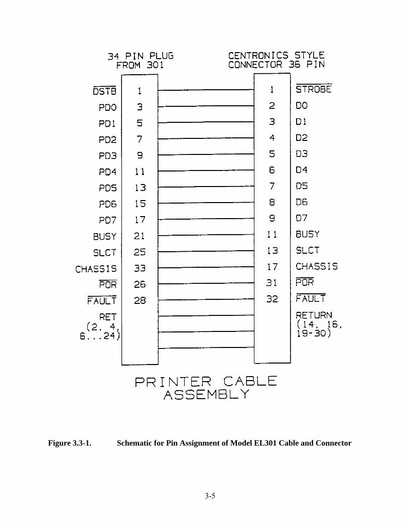
3. See Figure 3.3-1 for a schematic of the pin assignment of the cable and connectorfor the Model EL301 .
NOTE: The interface is an 8-bit parallel interface with signals consisting of: 8 databits, data strobe, printer busy, printer fault, and signal return. In addition, the outputdrive capability is sufficient to drive an LSTTL input.
4. Refer to Section 4 for instructions on selecting the parallel printer port outputduring file setup.
NOTE: The software is designed so that the Model EL301 waits 2 seconds forthe proper interface signals before displaying:
PRINTER NOT OKAY
and abandoning the requested output.
3-5
Figure 3.3-1. Schematic for Pin Assignment of Model EL301 Cable and Connector

3-6
3.4 Connecting the Model EL301 to an External Computer
1. Refer to the computer operator’s manual for specific instructions on setting up thecomputer to receive data from the Model EL301 microwell reader.
2. The serial port is of DCE configuration; that is, it is wired to look like a modem.See Figure 3.4-1 for the serial port connections.
NOTE: The interface is full duplex RS-232C serial with an RJ-24-style connector.It transmits at 1200 baud and uses 1 start bit, 8 data bits, 2 stop bits, and a hardware handshake. All characters sent from the serial port are ASCII coded.
3. Use the custom cable with its snap connector to connect the Model EL301 to anexternal computer for additional data manipulation. (See Figure 2.2.2-1 for thelocation of the serial port on the rear panel of the Model EL301.)
NOTE: Refer to Section 2.4 to purchase the optional custom cable. Serial must beenabled at file setup (see Figure 4.3.1-1).
3.5 Installing Interference Filters in the Filter Paddle
1. See Figure 2.2.1.1-1 for a detailed illustration of the interference filters and thefilter paddle for the Model EL301 .
NOTE: The filters are factory-mounted in protective filter cups that fit securelyinto the openings in the filter paddle.
2. Refer to Section 2.4 to order additional filters (and filter paddles, if desired).
3. Remove the filters in the paddle by gently tapping the filter paddle into the openpalm of your hand; the filters should be released from the openings in the filterpaddle.
NOTE: Never force the filters out of the paddle with a sharp object as this canscratch and permanently damage the filters.
4. Gently press the new filters into the openings on the filter paddle. Take care not totouch the filters themselves because fingerprints cause the optical density readingsto be inaccurate.

3-7
Figure 3.4-1. Serial Port Connections for the Model EL301

3-8

4-1
4 OPERATION
4.1 Introduction
The Model EL301Strip Reader is controlled from the reader’s front panel. Thissection describes how to operate the instrument including how to set up files aswell as how to read the microwell strips.
Even though the Model EL301is a portable reader, it is designed with manyfeatures and operation at first may appear quite complex. Read this sectioncarefully and go through all of the steps in Section 4.4.4 (Setting Up a File:Tutorial) to ensure that you fully understand the many features that this readercan provide.
4.2 Preliminary Procedures
Before turning on the Model EL301, confirm the following:
1. The reader has been installed according to the instructions inSection 3.
� All electrical cables are properly connected and grounded (refer to Section 3.1for details).
� All connections between the Model EL301and all peripheral devices aresecure as described in Sections 3.3 and 3.4.
2. The microwell strips to be used are clean and dust-free.
3. The interference filter lenses in the filter paddle are clean (refer toSection 5.2.3) and the working surface and the non-skid rubber feeton the bottom of the instrument are clean (refer to Section 5.2.2).
CAUTION
Operation of the Model EL301in direct sunlight is not recommendedbecause sunlight has all light frequencies and it can interfere with theoptical density readings.

4-2
4.3 Definitions
The following sections describe all of the operational functions of the Model EL301. If youare using this instrument for the first time, be sure to read Section 2.2.1 carefully to learn thefront panel locations and definitions of the buttons on the Model EL301 .
4.3.1 Display Windows on the Model EL301
See Figure 4.3.1-1 for a complete description of the alphanumerics that appear in the LCDwindow during a reading, or when the Data Display Mode is accessed (by pressing theDISPLAY/SET-UP button).
When the power to the Model EL301is turned ON, the instrument defaults to the DataDisplay window shown in Figure 4.3.1-1c. Pressing the DISPLAY/SET-UP buttontoggles the display between the Set-Up Display and the Data Display.
4.3.1.1 User Prompts
The Model EL301communicates with the operator by means of user prompts. The promptsensure that the file parameters and options are entered where required and that data entrysteps are followed in the proper sequence. For example:
1. When blanking a well or when reading in dual wavelength, the displayprompts the operator to enter the data in a specific order: This minimizesthe use of inaccurate data or the accidental erasure of stored data.
2. When in the submenus of file setup, pressing the DISPLAY/SET-UP buttondoes not switch to the Data Display screen; instead, a COMPLETE SETUPmessage is displayed. This forces the operator to step through each promptof a particular submenu and to fix any setup errors before exiting to the DataDisplay Mode.

4-3
WELL O.D. RESULT
where:
WELL = well file numberO.D. = optical densityRESULT = calculated result for ratio, linear equation, difference,
or limit call (+, -, or +/-)
a. Model EL301Display Window
F1 READY/MC 1AA1 0.542b -1.234
where:
F1 = file numberREADY = current status (3 options READY = ready to read well, W1 = reading
at filter wavelength W1, W2 = reading at filter wavelength W2)MC = memory flag (MC = memory clear, MF = memory full)1A = memory area designatorA1 = well location0.542 = optical density (can be negative if O.D. of well is less than
O.D. of blank well)b = well type (b = blank, s = standard, no letter = sample well)
b. Display Window Appearance During Reading
Figure 4.3.1-1. Display Windows Defined for the Model EL301

4-4
F1 SETUP L S P 8 D ABSORB Y N Y
where:
F1 = file numberSETUP = setup mode headerL = limits set headerS = serial output headerP = parallel output header8 = strip configuration (options = 8, 12, or 16)_ = cursor (moves when PROMPT pressed)D = wavelength mode (D = dual, S = single)ABSORB = calculation type (ABSORB = absorbance, RATIO = ratio,
LINEQU = linear equation, DIFF = difference)Y = limits set (Y = yes, N = no)N = serial output (Y = yes, N = no)Y = parallel output (Y = yes, N = no)
c. Display Window Appearance during Data Set-Up Mode
Figure 4.3.1-1. Display Windows Defined for the Model EL301(Continued)
4.3.1.2 Error Messages
User error messages inform the operator when procedural errors are made; for example:
1. When the display shows READY/MC it means that a particular strip in a particularfile is ready to be read; that is, the memory is clear. After the strip is read, the MCchanges to MF, memory full. If the operator forgets to change the well location orstrip designator, then the Model EL301will display the error message:
CLEAR MEMORYTO REREAD STRIP
This prevents the operator from accidentally reading over data stored in memory.

4-5
2. During the Set-Up Mode, if the operator attempts to enter the parameters in theincorrect order, an error message will appear on the screen to inform the operator ofthe problem.
3. If the DATA OUT button is pressed when the printer is enabled but the printer is nothooked up or is not on-line, the Model EL301will display the error message:
PRINTER NOT OKAY
NOTE: If DATA OUT is pressed and the external computer is not turned on or con-nected to the reader’s serial port, the display will continually show:
SENDING DATA
There is no way to resume normal reader functions from this condition except to turn thereader OFF and then ON again.
4. If CLEAR is pressed, the operator can switch from the Display Mode to the Set-UpMode by pressing the DISPLAY/SETUP button.
5. Remember that after reading a strip, the operator must prompt for the specific filelocation when switching from the Display Mode to the Set-Up Mode. If the specificfile location is bypassed, the Model EL301emits an audible double tone.
6. During initial filter calibration at power up, the message on the display instructs theoperator to:
REMOVE CARRIER THEN HIT ENTER
The reader senses the actual presence of the carrier and if ENTER is pressed but thecarrier is still in place, the reader will beep twice and the display will remain the same.

4-6
7. If single wavelength has been selected during the file setup but the W1/W2 button ispressed during the reading function, the reader will beep twice and the followingdisplay will alert the operator to this inconsistency:
F1 W1/W2 1a CHECK SETUP
4.3.2 Files
The Model EL301has 4 setup files: F1, F2, F3, and F4. Each file can be set up to define adifferent set of parameters (or modes) that determine which types of data are obtained. (Forexample, the file could be set up to read the strip using dual wavelength, a 12-well configura-tion, and to read absorbances only.) Each of these files functions independently of all otherfiles and indicates to the operator where the data are stored in the non-volatile RAM of theModel EL301 .
Within each file, the individual strips are labeled with a letter and a number. It is possible tohave 3 memory locations of A, B, and C. These memory locations are further identified as 1of 6 strips so that the strip locations are designated as: 1A, 2A,...6A, 1B,...6B, and 1C,...6C,thus giving a total of 18 possible strips within a single file. For example, a strip could be infile F3 with a memory location of B2. Each strip contains readings for up to 16 (2 x 8 con-figuration) microwells.
NOTE: The dual wavelength 8-well strip is considered a single strip. When all possiblemicrowell locations are multiplied together, the total number of microwell readings that canbe stored in the Model EL301memory equals 1,152 (or 12 full 96-well microplates). SeeFigure 4.3.2-1 for a graphic representation of how the file numbers, memory locations, andassociated microwell strips are accounted for in the calculations. It is clear from the figurethat different files can have the same memory locations (e.g., location A3 of F1, location A3of F4).
NOTE: Blanking values, standards, and ratios are maintained from strip to strip within thesame file.

4-7
4.3.2.1 Calculation Formats Available
There are 4 data reduction functions that can be chosen for the wells being read (refer toSection 4.3.3.4 for a complete definition of the data reduction that the Model EL301canperform):
1. 8-Well configuration: absorbance, ratio, linear equation, and limit.
2. 12-Well configuration: absorbance, ratio, linear equation, and limit.
3. 16-Well configuration: absorbance, ratio, linear equation, difference, and limit.Only the 16-well (2 x 8) configuration gives a difference value.
There are 6 characters reserved on the LCD for the calculation results. The display can show:
1. Concentration values of a 4-digit number with 1 digit to the left of the decimalpoint (e.g., 123.4, a positive value; -123.4, a negative value).
2. “+.+++” for overrange values (> 2.999).
3. “-.---” for underrange values (< -2.999).
4. “+,” “-,” or “+/-” if limits were set for the readings (e.g., if the upper limit were2 and the lower limit were 1, then “+” would be displayed for values > 2, +/- forvalues > 1 and < 2, and “-” for values < 1).
NOTE: Remember that LIMIT1 is the lower limit and LIMIT2 the upper limit;therefore:
Absorbance > LIMIT2 “+”LIMIT1 < Absorbance < LIMIT2“+/-”Absorbance < LIMIT “-”

4-8
Each File defines Data Reduction Programand the Location of Stored Data.
F1 F2 F3 F4
Each File contains 3Plates, (A, B, C)where strips areread and datastored.
A B C
Each Plate contains 6Strips, (1, 2, 3,4, 5, or 6)where wells areread and datastored.
1 2 3 4 5 6
Each Strip contains8, 12, or16 Wells.
8 12 16
Figure 4.3.2-1. Number of Wells Stored in Memory

4-9
4.3.3 Functions Performed by the Model EL301
The portable Model EL301Strip Reader is designed to function in much the same way aslarger, stationary readers. The following sections clearly define all of the operating functionsof the Model EL301. When you have completed reading the sections explaining these func-tions, then you are ready to follow the tutorial that takes you through all setup and operatingsteps of the portable reader. Section 2.2.1 describes the buttons on the Model EL301frontpanel. Some of the definitions contained in Section 2.2.1 are included in the following text toprovide continuity within this section as you are learning about the strip reader.
The operating functions performed by the Model EL301include:
1. Creating blanking wells and creating standards for ratio and linear equation forms ofdata reduction (refer to Section 4.3.3.1).
2. Clearing (refer to Section 4.3.3.2).
3. Reading with single or dual wavelengths, with or without setting limits forabsorbance and concentration values (refer to Section 4.3.3.3).
4. Performing data reduction on the data; the data reduction forms include: absorbance,ratio, linear equation, and difference calculations (refer to Section 4.3.3.4).
5. Transmitting data through the parallel and serial ports to a printer and externalcomputer, respectively, to obtain hard copies of the data or for further datamanipulation (refer to Section 4.3.3.5).
NOTE: The data is transmitted via the serial interface in ASCII code.
4.3.3.1 Blanking and Standards
4.3.3.1.1 Blanking
The BLANK button is located to the right of the DATA buttons on the Model EL301frontpanel. It is used to instruct the microprocessor to read the current microwell aligned with thefilter chamber as a blank. When the Data Display window is shown on the LCD, this buttonenables the operator to read the optical density of the microwell aligned over the filter cham-ber. This value is used as the blanking value that is subtracted from all other microwellreadings in that file until a different blanking value is entered. If the microwell carrier is notproperly aligned over the filter chamber, pressing BLANK has no effect and the carrier shouldbe realigned to give a valid well location.

4-10
NOTE: If there is no microwell carrier in place when BLANK is pressed, that well location isblanked against air. Be sure to remove the microstrip carrier so that the reader does not blankon the black carrier. If the strip has been cleared and then blanking is initiated on that strip,then the blanking value is retained and the operator is not forced to re-blank unless he or shewishes to re-blank on a particular well.
When a well is successfully blanked, the Model EL301emits an audible tone when BLANK ispressed. A blanked well shows up on the display or on the printout as the optical densityvalue immediately followed by the lowercase letter “b.” Blanks can be carried over fromstrip-to-strip within the same file by simply continuing to read the sample wells. A new blankcan replace the current blank if BLANK is pressed before beginning to read a new microwellstrip. The new blanking value is subtracted from all subsequent readings.
From the previous paragraphs, it is apparent that when the operator begins a new microplatereading sequence, the Model EL301will automatically retain the blanking values. Thesevalues will be carried over into the reading of subsequent strips unless one of the followingconditions arises:
1. Operator returns to SETUP Display to change filter parameter from Single toDual or Dual to Single: If this situation occurs, then all blank locations are retainedonly for the samples already read; these values are cleared from memory as theblanking locations. The Model EL301forces the operator to read in the new blank(s)value(s) at the point in the prompting sequence where he or she changed to a newwavelength setup.
If the operator changes from Single to Dual wavelength, then the Model EL301willprompt for both filter wavelength readings; if the operator changes from Dual toSingle, then the EL301will prompt for just one filter wavelength reading.
2. Operator presses CLEAR key during reading of a Blank or reading of aSample: When CLEAR is pressed, all Samples and Blanks are deleted from memoryand theModel EL301prompts the operator to enter new blanks for the microwellstrip. If no Blanks have been read in the strip, only the Sample wells will be clearedfrom memory but any Blanks already retained for the preceding strips which com-prise the microplate will be retained and used to blank against the new Sample wellOD values.
3. Operator presses the BLANK key on a new microwell strip: When this occurs,the Model EL301ignores any blanks already programmed into the microplate SETUPfor all subsequent strips to be read. The Model EL301will accept the new Blanksentered by the operator at the current strip and use them for the subsequent readings.

4-11
Remember to observe the following protocol when using the blanking function of theModel EL301 :
1. When the Model EL301is turned ON or after a blank has been deleted by pressingthe CLEAR button, a new blanking well must be entered before beginning to read themicrowell strip. An attempt to read the strip will cause the unit to display the errormessage:
NO BLANKING YET
2. Blanks must be read first if not already established for that particular file setup.When BLANK is pressed, the READY/MC on the display changes to the first wavelength to be read, W1, so that the display shows W1/MC.
3. Consecutive blanks are created by pressing BLANK for the first well in the strip andthen sliding the microwell carrier to the next valid well location and pressingBLANK again. This process can be repeated for as many consecutive blanks asdesired in that strip.
NOTE: The consecutive blank well values are averaged together and it is thisaverage value that is subtracted from all sample wells; however, one well must beread to trigger the blank-averaging routine.
4. Blanks cannot be read within the strip after the first sample is read.
5. Standard wells (if defined in the file setup) must be entered immediately followingthe blanking well but before any sample wells are read. (Refer to the followingSection 4.3.3.1.2 for the description of standard wells.)
6. Blanks and standards entered for the first wavelength, W1, of a dual wavelengthreading must also be entered on the same well location during the second wavelength,W2, reading. (As demonstrated in the tutorial, Section 4.4.4, the Model EL301prompts the operator for these blanks and standards in the proper sequence anddisplays error messages if this sequence is not followed.)
NOTE: If a previously used file is not cleared completely (with the exception ofStrip 1), the blanking function will continue even if CLEAR is pressed.

4-12
4.3.3.1.2 Standards
When LINEQU or RATIO is selected as the calculation option for data reduction during filesetup, standard wells must be entered as a file parameter. (Refer to Section 4.3.3.4 for acomplete description of the calculation options for data reduction.)
Remember to use the following protocol when setting standards for a Model EL301file:
1. During file setup, decide which well(s) should be used as the standard(s).
NOTE: Standard wells can only exist on the first strip of a 6-strip group. (Picture themicrowell strips combined together to form a full 96-well microplate.) The standardsdesignated for this first strip can be used for all strips within this 96-well microplateequivalent.
2. The standards designated in Step 1, preceding, can be used for other microplateequivalents within the same file; that is, for A, B, or C. The carryover of thesestandards is optional. The display shows the following prompt after the blank is read:
NEW STANDARDS?OPTION OR ENTER
Pressing the OPTION button changes the display to:
SAME STANDARDS?OPTION OR ENTER
At this point, the operator can decide to retain or change the designated standards bypressing ENTER when the desired prompt appears on the display.
NOTE: When a file is cleared (by pressing CLEAR) and re-read, the reader queries theoperator for NEW or SAME STANDARDS?

4-13
3. Standard wells (as designated in the file setup) must be read immediatelyfollowing the reading of blanking wells (described in Section 4.3.3.1, preceding)but before the sample wells are read.
NOTE: If the operator forgets that a standard has been designated and pressesREAD after the blanking well is entered, the Model EL301emits an audible toneand dis plays the following error message for 3 seconds:
F1 W1/MF 1AREAD STANDARDS
4. Standards and blanks entered for the first wavelength, W1, of a dual wavelengthreading must also be entered on the same well locations during the second wavelength, W2, reading. The Model EL301prompts the operator for these standardsand blanks during file setup.
4.3.3.2 Clearing
Data is saved in the Model EL301non-volatile RAM even if the power is removed. TheCLEAR button clears digits in the numerical entry prompts. This clearing action takes placewhen entries are made for the concentration values used for RATIO and LINEQU calcula-tions and when limit values are chosen.
Remember to observe the following protocol when using the clearing function of the reader:
1. During the file setup, pressing CLEAR clears the bottom line of the display andreturns the prompt to the last chosen parameter. This enables the operator to re-enterdata for concentrations and limits.
2. During the Data Display Mode, pressing CLEAR clears the data stored in either thefile, the plate, or the strip, depending on the location of the cursor when CLEAR ispressed. The parameters associated with the memory location of the setup file are notcleared when the data entries are removed. The cursor must be placed under A, B, orC if the entire memory location is to be cleared.
NOTE: Place the cursor under the data memory location to be cleared before press-ing CLEAR. (An entire file can be cleared instead of just a strip if the cursor is incor-rectly placed under the file designator instead of the strip designator.)

4-14
3. Remember to use CLEAR to clear any blanks, standards, or differences that are not tobe carried over to the new file to be read. (Refer to Section 2.2.1 for additionalinformation.)
4.3.3.3 Reading
The READ button is located in the upper lefthand corner of the Model EL301front panel.When the microwell strip carrier is moved from well to well, the Data Display window showseither the previous reading for the well aligned with the filter chamber or “_._ _ _” if there isno previous reading. The Model EL301emits an audible tone when the well has been readsuccessfully. The reading appears in the display window such that the well location appearsover WELL, the optical density reading appears over O.D., and any calculated results forratio, linear equation, or difference appear over RESULT.
Some wells read by the Model EL301will have Absorbance values that are designated asOVERRANGE values (i.e, with OD’s > 2.999) or UNDERRANGE (i.e., with OD’s< -2.999). (In the following description, only OVERRANGE will be discussed but the sameapplies to the UNDERRANGE values that are represented on the printout as: -.---.) Thesevalues are treated differently depending on the parameter Setup. In all cases, however, theOVERRANGE OD values are considered to be invalid test data. The following listdescribes how OVERRANGE values are treated in different situations:
1. During reading of Dual Wavelength: If either of the 2 filter readings on a givenSample are detected to be OVERRANGE OD values, then the final Absorbanceresult is invalidated. Any subsequent calculations performed are also invalidated.The Model EL301display warns the operator that an OVERRANGE condition existsandthe OD appears on the printout as: +.+++. Any values intended for the ResultsColumn on the printout appear as: ?.??? for the OVERRANGE well.
2. Standard well is detected as OVERRANGE: If this occurs, then all Standards forthat microwell strip are considered invalid. The operator is warned that the STD wellis OVERRANGE in the display window and the OD appears on the printout as:+.+++ and all results for each Standard and Sample well read are printed as: ?.???.
3. During Difference or Ratio calculations: For these calculations, anyOVERRANGE values will invalidate the OD value and the calculation result for theOVERRANGE well(s). The LCD display will show a warning message, ODOVERRANGE, and the printout will show: +.+++ and ?.??? for the Absorbancevalue and result, respectively.

4-15
4. Blank is detected as OVERRANGE: If the Blank is OVERRANGE, it is ignoredand the Model EL301prompts the operator to re-blank until the unit has been blankedon a valid well. If the invalid Blank is one of a number of blanks that are averagedtogether to give a final blanking Mean, then the invalid Blank value is not used in theaveraging process. The Model EL301display will warn the operator that the well isOVERRANGE and the printout will show the Blank well (“b”) Absorbance as:+.+++ and the calculated result as: ?.??? (if any results were expected based on theparameter Setup).
5. Sample well is detected as OVERRANGE: If this occurs, then the Model EL301display warns the operator that the OD is OVERRANGE and the display shows thevalue as: +.+++. The OVERRANGE values appear on the printed as: +.+++and ?.??? for the Absorbance value and result, respectively.
Remember to use the following protocol when using the reading function of the ModelEL301:
1. Ensure that all blanks (Section 4.3.3.1.1) and standards (Section 4.3.3.1.2)designated in the file setup are entered before trying to read the optical density of asample well.
NOTE: Pressing READ causes the Model EL301to read the optical density of thewell aligned over the filter chamber and then to subtract any blanking values from theoptical density reading; it is this difference that is displayed on the LCD.
2. The wells are read by sliding the microwell carrier on the raised guide rail on thefront panel (refer to Section 4.4.2). When the well is properly aligned over the filterchamber as indicated by a new well location on the display, pressing READ will readthe new well.
NOTE: If the well is not aligned over the filter chamber, pressing READ has noeffect.
3. When all of the samples in the strip have been read, change the strip identifier or thefile number to read the next microwell strip.
4. The same well can be read repeatedly by continually pressing READ; however, onlythe most current reading is retained in memory.
5. The CLEAR button can be used at any time during the reading of the wells (refer toSection 4.3.3.2 for a complete description of the clearing function).

4-16
The actual reading of the microwells is determined by the following user-definedconditions:
1. Reading at single or dual wavelength (refer to Section 4.3.3.3.1).
2. Setting limits for absorbance and concentration values (refer to Section 4.3.3.3.2).
4.3.3.3.1 Single Wavelength versus Dual Wavelength
The Model EL301can measure optical densities by reading the microwell at a single wave-length or by reading the microwell twice, first at the filter wavelength, W1, and then at thefilter wavelength, W2.
Remember to observe the following protocol when reading at single or dual wavelengths:
1. Both filters are calibrated after power up. It is important that the instructions shownon the reader display are followed exactly.
2. Select “S” for single and “D” for dual wavelength during the file setup.
3. The W1/W2 button toggles between the interference filter wavelengths W1 and W2only for dual wavelength designations on the Data Display window.
NOTE: Filter W1 must be used for readings before filter W2 can be used.
4. Calibration is performed on both filters when the Model EL301is turned ON.
NOTE: The reader must be turned OFF and then ON to initiate the recalibrationprocess when switching from double-to-single wavelength or from one single wave-length to another single wavelength.
5. The Model EL301software ensures that the microwell strip carrier is removed beforecalibration by displaying a user prompt on the LCD. The software cannot, however,detect if a filter is actually mounted in the filter paddle or which filter is mounted inthe paddle.
NOTE: The operator must ensure that the proper filter is installed in the proper filterpaddle position during the calibration procedure.

4-17
6. Press W1/W2 to toggle between the filters mounted in the filter paddle. Whenreading using dual wavelengths, the absorbance values for all of the wells are initiallystored but then they are replaced by the difference W1 - W2 as soon as the readings atW2 are taken. No values are shown on the display until the W2 readings are taken.
NOTE: It is not possible to obtain the individual values for W1 or W2 without re-reading the strip in the single wavelength setting.
7. If single wavelength is selected during file setup but the W1/W2 button is pressedduring the reading function, the Model EL301will emit an audible beep and display:
F1 W1/MC 1ACHECK SETUP
8. If single wavelength measurements at the W2 wavelength are desired, switch OFF theunit, change filters, and recalibrate.

4-18
4.3.3.3.2 Setting Limits for Absorbance and Concentration Values
An upper and a lower limit can be selected for the data reduction calculations. During the filesetup, the operator can choose to use limits by toggling the OPTION button to “Y” for yeswhen the cursor is under the “L” on the setup display. When the yes option is entered, theModel EL301 first prompts for the lower limit, LIMIT1, and then the upper limit, LIMIT2.Each of these limits defines a threshold (or cut-off) value that is interpreted by the micropro-cessor.
Remember to observe the following protocol when using limits during data reduction calcula-tions:
1. The values for the limits must be in the same measurement units as the calculation optionthat is selected.
Calculation Type Limit Units
ABSORBANCE AbsorbanceRATIO ConcentrationLINEQU (Linear Equation) ConcentrationDIFF (Difference) Absorbance
2. When the calculated data appear on the display or the printout, the following symbolsare used:
“+” For values greater than the upper limit (Abs.> LIMIT2).“+/-” For values between the upper and lower limits
(LIMIT1 < Abs. < LIMIT 2).“-” For values less than the lower limit (Abs. < LIMIT1).
NOTE: The lower limit is always LIMIT1 and it is always entered first in the promptingsequence.
3. Within a given file number, the following combinations of calculation options may beused:
ABSORBANCE/RATIO ABSORBANCE, RATIO, LIMITABSORBANCE/LINEQU ABSORBANCE, LINEQU, LIMITABSORBANCE/DIFF ABSORBANCE, DIFF, LIMITABSORBANCE/LIMIT

4-19
NOTE: Single or dual wavelength readings can be taken for any of the preceding combi-nations of options.
4. The concentration limits are entered and displayed as: “_ _ _ . _” and the opticaldensity (absorbance) limits are entered and displayed as:“_ . _ _ _” (e.g., 123.4 and 1.234, respectively).
5. When the calculation option is changed in the file setup, the limits option isautomatically changed to “N” (no). This is intended to prompt the operator to re-enter the limits for the new calculation option.
4.3.3.4 Data Reduction
There are 4 kinds of data reduction that can be selected on the Model EL301:
1. ABSORB (Absorbance): Used to read, display, and print only the optical densityvalues of the microwell strips (refer to Section 4.3.3.4.1).
2. RATIO: Used to read, display, and print the absorbance values and then to calculatea concentration value by creating ratios between the sample wells and a known stan-dard well (refer to Section 4.3.3.4.2).
3. LINEQU (Linear Equation): Used to read, display, and print calculatedconcentration values of sample wells. These calculations are based on extrapolationfrom the curve generated by plotting the observed optical densities against the knownconcentrations of from 2 to 5 standard wells (refer to Section 4.3.3.4.3).
4. DIFF (Difference): Used to read, display, and print the calculated differencebetween the optical densities of the 16-well configuration (2 x 8); that is, the value ofA1 - A2 (refer to Section 4.3.3.4.4).
4.3.3.4.1 Absorbance
Remember to observe the following protocol when using the ABSORB function:
1. Select a blank well (or group of blank wells) whose value will be subtracted from allsample readings (refer to Section 4.3.3.1.1 for a description of blanking).
2. Select single or dual wavelength with which to read the microwell strips.

4-20
3. Set limit values (if desired) for the optical densities (refer to Section 4.3.3.3.2 forsetting limit values).
4. Remember that the calculation type is reset to ABSORB when the strip configurationis changed from the 16-well to 8-well configuration. This prevents the carryover ofinvalid standard wells.
4.3.3.4.2 Ratio
This method of data reduction is used to calculate the concentration of the sample wells. Theoperator enters the known concentration of a standard well, reads the optical density of thatwell, sets up a ratio of the known concentration to the measured optical density of the stan-dard well, and uses this value to calculate the concentration of the sample wells when only theoptical densities are measured. Mathematically this is expressed by the equation:
ConcentrationStandard
= ConcentrationSample
__________________ __________________
AbsorbanceStandard
AbsorbanceSample
For example, with a CONCENTRATION of the known STANDARD is 200 UG/ML andreader-determined ABSORBANCE of 0.200, the CONCENTRATION of the SAMPLE canbe back-calculated by measuring the ABSORBANCE of the sample well and using the pre-ceding equation such that:
200 UG/ML = “x” UG/ML__________ __________
0.200 Abs. 0.100 Abs.
“x” = 100 UG/ML
This is the calculated SAMPLE CONCENTRATION.

4-21
Remember to observe the following protocol when using the RATIO function:
1. The output of the ratio calculation consists of a number from 000.0 to 999.9.
2. The operator can choose concentration units of nanograms per milliliter (NM/ML),micrograms per milliliter (UG/ML), or can choose no units (NONE).
3. The operator can choose limits for the concentration values (refer to Section4.3.3.3.2).
4. The operator can choose to blank against air, use one blank well, or a group of blankwells. Any blanks are subtracted from the standard well as well as the sample wells(refer to Section 4.3.3.1.1).
5. The blank wells must be read first immediately followed by the standard well orwells (refer to Section 4.3.3.1.2).
NOTE: A standard well cannot also be used as a blank well.
6. RATIO and LINEQU cannot be used in the same file (they are mutually exclusive).

4-22
4.3.3.4.3 Linear Equation
The linear equation form of data reduction enables the operator to obtain the concentrationvalues for sample wells by reading the optical densities of these wells. As shown in Figure4.3.3.4.3-1, the microprocessor in the Model EL301uses the classic point/slope equation tocalculate the sample concentration values. The point/slope equation is as follows:
y = mx + b
where:
y = measured optical density of the sample well (shown on y-axis)
m = the slope of the best-approximation line drawn through the points by the 2 to 5standard wells of known concentration and measured optical densities
x = calculated concentration of the sample well (this value is extrapolated from themeasured optical density of the sample, shown on the x-axis)
b = the y-intercept of the line (as drawn on the figure, the y-intercept would be zero).
The operator must provide the concentrations for 2 to 5 standard wells and read the opticaldensities of the wells to create the line used in the linear equation form of data reduction.
Remember to observe the following protocol when using the LINEQU function:
1. All blank wells must be read first (refer to Section 4.3.3.1.1).
NOTE: Only the first standard well can also be used as a blank.
2. All standard wells (from 2 to 5) must be read immediately following the blankingwell (refer to Section 4.3.3.1.2).
3. Standard wells must be entered sequentially and only the first location will bedefined.
NOTE: All standards must appear on the first strip of the microplate (consistingof strips treated as a full 96-well microplate).
4. Limits can be set for the concentration values (refer to Section 4.3.3.3.2).

4-23
5. The standard well location for LINEQU is reset to the first well of the strip whenthe number of standards is changed in the file setup. (This is done to preventinvalid well locations from carrying over to the new setup.)
6. RATIO and LINEQU cannot be used in the same file setup; they are mutuallyexclusive.
Figure 4.3.3.4.3-1. Graphic Interpretation of Linear Equation

4-24
4.3.3.4.4 Difference
The DIFF form of data reduction is used only with the 16-well (2 x 8) configuration. TheModel EL301microprocessor calculates the difference by subtracting the value of the opticaldensity of a well in the first strip of the 2 x 8 strip from the corresponding well in the secondstrip; that is, A2 - A1, B1 - B2.
Remember to observe the following protocol when using the DIFF function:
1. Enter blanks first as described in Section 4.3.3.1.1.
2. Enter limit values (if desired) as described in Section 4.3.3.3.2.
3. Note that only the calculated difference is displayed or printed out with theABSORBANCES.
NOTE: If the LIMITS option is selected, only the calls “+,” “+/-,” and “-” are printedand if LIMIT1 = LIMIT2, the only “+” and “-” are printed.
4.3.3.5 Data Output to Peripheral Devices
The DATA OUT button transmits data out of the parallel printer port and the RS-232C serialport depending on the options selected during file setup.
Remember to observe the following protocol when using the data output function:
1. During file setup, select the options to transmit data out of the ports on the ModelEL301. (Refer to Section 3.3 for transmission to the printer and Section 3.4 fortransmission for the external computer.)
2. Data can also be transmitted out the ports by locating the cursor under the FileNumber or the Memory Location on the Data Display and pressing the DATA OUTbutton. The following message appears on the display:
SENDING DATA
3. If DATA OUT is pressed during data transmission, the transmission will beterminated.
4. When the Data Set-Up display appears, pressing DATA OUT causes the file setup tobe printed.

4-25
5. If DATA OUT is pressed and the printer is not hooked up to the Model EL301, anerror message appears on the display to inform the operator that data transmissionwas unsuccessful:
PRINTER NOT OKAY
6. If DATA OUT is pressed and the computer is not hooked up to the serial port (or isnot turned on), the reader will try to transmit data. The reader will hang up at thispoint.
NOTE: The only way to resume operation of the reader is to turn the reader OFF andthen ON again. The operator must ensure that the setting for the serial port in the Set-Up Display (“Y” or “N” underneath the “S”) corresponds to the setup being used.
7. The printout is limited to a width of 40 characters.
8. For the dual wavelength mode, well data are only reported if the wells have been readand blanked in both wavelengths W1 and W2.
4.4 Operation
4.4.1 Power ON
The Model EL301uses a non-volatile RAM (NVRAM); therefore, when the reader is turnedON, all user data storage and file setup information is retained.
1. Refer to Section 2.2.1 for the location of the ON/OFF switch on the Model EL301.
2. Refer to Section 3 for a complete description of electrical safety and how to connectthe Model EL301to peripheral devices.
3. Turn ON the Model EL301and then turn ON any peripheral devices connected to thereader.
NOTE: Ensure that the printer (if used) is on-line and ready to receive data. Enablethe serial port only if you intend to connect the reader to a computer.
4. Refer to the following Sections 4.4.2 and 4.4.3 for instructions on using themicrowell strip carrier and the filter paddle, respectively.

4-26
4.4.2 Positioning the Microwell Carrier on the Model EL301Guide Rail
1. Refer to Section 2.2.1.2 for a complete description of the components that comprisethe microwell strip carrier.
2. See Figure 4.4.2-1 that shows how the carrier slides along the raised guide rail on thefront panel of the reader. The figure also shows that bottom view of the carrier.
NOTE: There are 2 grooves on the bottom of the carrier; these are used when the 16-well (2 x 8) configuration is used. The groove closest to the carrier edge positions themicrowell strip furthest from the opposing edge over the filter chamber.
3. Observe the detent mechanism that is suspended from the optics arm that works inconjunction with the grooved surface on the microwell strip carrier. This mechanismensures that each well being read is aligned over the filter chamber.
4.4.3 Inserting the Filter Paddle into the Model EL301
1. Refer to Section 2.2.1.1 for a complete description of the filter paddle components.
2. Refer to Section 3.5 if you wish to change the interference filters mounted in thefilter paddle.
3. Ensure that the proper filters are placed in the appropriate openings in the filterpaddle. (Filter W1 is placed in the opening that enters the paddle receptacle first as youinsert the paddle.)
4. Use the indicator lines on the filter paddle for visual verification that the proper filteris in the filter chamber.

4-27
Figure 4.4.2-1. Positioning the Microwell Strip Carrier on the Model EL301Guide Rail

4-28
4.4.4 Setting Up a File: Tutorial
This section is designed to go through every step in setting up a file on the Model EL301 .Operation of the Model EL301is described in a stepwise manner. This section has beensubdivided into identifiable functions to enable the user to locate the specific steps required toperform a particular function.
Perform all of the operational procedures described in Sections 4.4.4.1 through 4.4.4.6 to setup the file parameters and then perform the procedures in Section 4.4.5 to actually read amicrowell strip.
4.4.4.1 Power Up Setup and Calibration
1. Turn ON the power to the Model EL301 . The display will show:
+::+::+::+::+::+::+::+::+::+::+::+::+::+::+::+:+::+::+::+::+::+::+::+::+::+::+::+::+::+::+::+:
for approximately 3 seconds.
2. When the Model EL301is turned ON, the display will show:
REMOVE CARRIERTHEN PRESS ENTER
Manually remove the carrier; the display will show:
INSERT FILTER W2 THEN HIT ENTER
3. Insert the filters into their protective cups in the filter paddle (refer to Section 3.5 forfilter installation procedures).
NOTE: The operator must ensure that the filters are mounted in the correct slots inthe filter paddle (observe the indicator lines and the stamped W1 and W2 on the filterpaddle). In addition, the reader cannot determine if the filter paddle is properly in-serted into the filter paddle receptacle; again, this is the responsibility of theoperator.

4-29
4. Press ENTER; for approximately 2 seconds the display will show:
CALIBRATINGWAVELENGTH W2
When calibration is complete for that filter, the display will show:
INSERT FILTER W1 THEN PRESS ENTER
Push the filter paddle into the W1 position and then press ENTER; for approximately2 seconds the display will show:
CALIBRATING WAVELENGTH W1
5. When the reader has calibrated for the second filter, the reader is ready to be usedread microwell strips. The following display will appear:
F1 READY/MC 1A _ _ _
6. If FILE 1 indicated in the preceding display is set up as desired begin reading; if thesetup must be changed, proceed to Section 4.4.4.2 to change the file number andmemory location.
4.4.4.2 File Number and Memory Location Setup and Flowchart
1. The display will show:
F1 READY/MC 1A _ _ _

4-30
NOTE: The cursor is positioned under the Memory Area Designator. (Refer toSection 4.3.1 for definitions of the display windows.) When the preceding display ap-pears, there is no carrier in place and the memory is clear as designated by MC; if thememory were full, MF would appear in place of MC.
2. Press OPTION repeatedly to change the Memory Area Designator; that is, 1A, 2A,3A, 4A, 5A, or 6A.
NOTE: The cursor remains under the numbers which change. When all of the op-tions have been cycled through the display wraps around and returns to the firstoption, 1A.
3. When the display shows the memory location number desired, press PROMPT toadvance to the next parameter setting; the display will show:
F1 READY/MC 1A_ _ _
NOTE: The cursor has moved under the letter of the Memory Area Designator.
4. Press OPTION to change the letter designator from A to B to C and back to A.
5. When the display shows the memory location letter desired, press PROMPT toadvance to the next parameter setting; the display will show:
F1 READY/MC 1A_ _ _
NOTE: The cursor has moved under the number of the Memory File Number.
6. Press OPTION to cycle through the Memory File Number options: F1, F2, F3, andF4.
NOTE: As you cycle through the Memory File Locations the display differ from thatshown in Step 5, preceding, because the various files may have been set up previouslyor they may actually contain data from readings that have not been cleared.
7. Proceed to Section 4.4.4.3-1 to set the microwell strip configuration and the wave-length options.

4-31
4.4.4.3 Microwell Strip Configuration and Wavelength Options Setup
1. The display (from Section 4.4.4.1, preceding) will show:
F1 READY/MC 1A_ _ _
2. Press DISPLAY/SETUP; the display will show:
F1 SETUP L S P8 S ABSORB N N Y
NOTE: The cursor is positioned under the well configuration number.
3. Press OPTION to cycle through the 3 microwell configurations: 8, 12, and 16 (2 x 8).
4. When the cursor is positioned under the configuration number desired, pressPROMPT to advance to the next parameter setting; the display will show:
F1 SETUP L S P8 S ABSORB N N Y
NOTE: The cursor is positioned under the single/dual wavelength designator (“S”and “D”).
5. Press OPTION to choose between single or dual wavelength (“S” or “D”).
6. When the cursor is positioned under the wavelength option desired, press PROMPTto advance to the next parameter setting; the display shows:
F1 SETUP L S P8 S ABSORB N N Y
NOTE: The cursor is positioned under the calculation-type designator.
7. Proceed to Section 4.4.4.4 to set the calculation options.

4-32
4.4.4.4 Calculation Options Setup
1. The display will show:
F1 SETUP L S P8 S ABSORB N N Y
NOTE: Although ABSORB is selected at this point in the setup, this function is notreally a calculation; it is simply the reading of the optical density of the microwells.
2. Press OPTION; the display will show:
F1 SETUP L S P8 S RATIO N N Y
3. Press OPTION; the display will show:
F1 SETUP L S P8 S LINEQU N N Y
4. Press OPTION; the display will show:
F1 SETUP L S P8 S DIFF N N Y
5. Press OPTION; the display will show:
F1 SETUP L S P8 S ABSORB N N Y
NOTE: All of the calculation options have been presented at this point and the displayhas wrapped around to the first option, Absorbance.

4-33
6. When the calculation option desired (from Steps 2 through 4, preceding) appears onthe display, press PROMPT to enter that option and advance to the next parametersetting:
� If the option ABSORB is desired, proceed to Section 4.4.4.5.1 to select the limit(cut-off) options.
� If the option RATIO is desired, proceed to Section 4.4.4.4.1 to select the ratiooptions.
� If the option LINEQU is desired, proceed to Section 4.4.4.4.2 to select the linearequation options.
� If the option DIFF is desired, proceed to Section 4.4.4.4.3 for the flowchart fordifference calculations.
NOTE: DIFF is similar to ABSORB in that there are no additional options to beselected once the calculation type is selected.
7. When the cursor is under the calculation option desired, press PROMPT to advanceto the next parameter setting or to the additional calculation option parametersettings for RATIO and LINEQU.
4.4.4.4.1 Ratio
1. When the calculation option RATIO is selected, the display will show:
F1 SETUP L S P8 S RATIO N N Y
2. Press ENTER to enter the option RATIO; the display will show:
STDS IN STRIP 1STD WELL A1
NOTE: The cursor is under the well row designator.

4-34
3. Press OPTION to cycle through the well row options: A1, B1, C1, D1, E1, F1, G1,and H1.
4. When the letter designator over the cursor is the one desired, press ENTER to enteryour choice and advance to the next parameter; the display will show:
STDS IN STRIP 1UNITS NONE
5. Press OPTION to cycle through the available measurement units: NONE, UG/ML,and NG/ML.
6. When the desired units of measurement appear on the display, press ENTER to enterthat choice; the display now will show:
STDS IN STRIP 1STD CONC = 000.0
NOTE: The cursor is under the first digit of a concentration value.
7. Press OPTION to cycle through the numbers: 0, 1, 2,..., 9 for the first digit.
8. If DISPLAY/SETUP is pressed at any time in this standards setup, thedisplay will show:
STDS IN STRIP 1COMPLETE SETUP
This message will stay on the display for approximately 2 seconds and then the screenwill return to the prompting sequence.
9. When the cursor is under the number desired for the first digit, press PROMPT toenter that number and to advance to the next parameter; the display will show:
STDS IN STRIP 1STD CONC = 000.0
NOTE: The cursor is positioned under the second digit of the concentration.

4-35
10. Press OPTION to cycle through the numbers 0 through 10 (as in Step 7, preceding).
11. Use a combination of PROMPT and OPTION to cycle through the numbers for theremaining digits of the standard concentration.
NOTE: You can enter concentration values from 000.0 to 999.9.
12. When you have the desired concentration displayed on the screen, press ENTER toenter that number and advance to the next parameter in the set-up display.
13. Proceed to Section 4.4.4.5 to select limits.
4.4.4.4.2 Linear Equation
1. When linear equation is to be chosen, the display will show:
F1 SETUP L S P8 S LINEQU N N Y
NOTE: The cursor is positioned under the option LINEQU.
2. Press ENTER or DISPLAY/SETUP.
NOTE: Use ENTER if you have new values to enter, use DISPLAY/SETUP if theprogram has been set up and needs no change.
1. If DISPLAY/SETUP is pressed, the display will show:
F1 SETUP L S P8 S ABSORB N N Y
NOTE: The cursor is positioned under the LIMITS HEADER. Proceed toSection 4.4.4.5.
2. If ENTER is pressed, the display will show:
STDS IN STRIP 1# OF STDS = 2
NOTE: The cursor is positioned under the standards number.

4-36
3. Press OPTION to cycle among the number of standards available for linear equationcalculations: 2, 3, 4, and 5.
4. When the number above the cursor is the number of standards desired, press ENTER;the display will show:
STDS IN STRIP 11ST STD A1
NOTE: The cursor is positioned under the letter designating the well row.
5. Press OPTION to cycle among the row designators available for linear equationcalculations: A1, B1, C1,...,H1, A2, B2,..., G2.
NOTE: The full 16-well (2 x 8) number of wells are represented by these letter andnumber designators. The options that can be cycled through, of course depend on thewell configuration selected earlier in the setup procedures.
6. When the desired strip location designator is displayed on the screen, press ENTER;the display will show:
STDS IN STRIP 1UNITS NONE
7. Press OPTION to select the desired concentration units from: NONE, UG/ML, andNG/ML.
8. When the desired concentration units appear on the display, press ENTER; thedisplay will show:
STDS IN STRIP 11ST CONC = 000.0
NOTE: The cursor is positioned under the first digit of the concentration value.
9. Press OPTION to cycle through the numbers 0 through 9.
10. When the desired first digit of the concentration appears on the display, pressPROMPT; the display will show:
STDS IN STRIP 11ST CONC = 000.0

4-37
11. Use a combination of OPTION and PROMPT to cycle through the numbers andmove the cursor to the adjacent digit.
12. When the desired concentration appears on the display, press ENTER; the displaywill show:
STDS IN STRIP 12ND CONC = 000.0
13. Use a combination of OPTION and PROMPT to cycle through the numbers0-9 and to move the cursor under the digit to be changed.
14. When the desired concentration appears on the display, press ENTER; if all standardconcentrations are entered, the display will show:
F1 SETUP L S P8 S LINEQU N N Y
15. Press PROMPT to advance to the next parameter to be selected.
16. Proceed to Section 4.4.4.5 to select the LIMITS option.
4.4.4.4.3 Difference
1. NOTE: If DIFF is selected, there is no OPTION; that is, pressing OPTION has noeffect.
2. Proceed to Section 4.4.4.5 for the next parameter selection: Setting Limits.

4-38
4.4.4.5 Limit Options Setup
For simplicity, only ABSORB will be followed through the remaining permutations in theprompting sequence.
1. When PROMPT is pressed after the calculation option is chosen, the display willshow:
F1 SETUP L S P8 S ABSORB N N Y
NOTE: The cursor is under the LIMITS header.
2. Press OPTION to choose between no limits (“N”) and limits (“Y”).
When no limits are chosen, press PROMPT to advance to the next parameterselection; the display shows:
F1 SETUP L S P8 S ABSORB N N Y
The cursor moves to the right and is positioned underneath the serial port headerwhich also has “Y” and “N” selections available.
3. When limits are chosen, the display shows:
F1 SETUP L S P 8 S ABSORB Y N Y
4. If the limits stored in the reader’s memory do not need to be changed, pressPROMPT to move the cursor to the next parameter.
5. If the limits need to be entered for the first time or changed, press ENTER; thedisplay will show:
F1 LIMITS SETUPLIMIT1 = _0.000
NOTE: The cursor is positioned to the left of the limit (cut-off) value.

4-39
6. Press OPTION to toggle between positive values (no sign shown) and negative values(“-”); for negative values the display will show:
F1 LIMITS SETUPLIMIT1 = -0.000
7. Press PROMPT to move the cursor to the right under the first digit of the limit value;the display will show:
F1 LIMITS SETUPLIMIT1 = -0.000
8. Press OPTION to toggle between “0, 1, and 2” for the number to the left of the fixeddecimal point; for example, the display might show:
F1 LIMITS SETUPLIMIT1 = -2.000
9. Press PROMPT to move the cursor to the right of the decimal point.
NOTE: For these places, pressing OPTION cycles through the digits “0 through 9”thereby enabling the operator to select limits from “-2.999” to “2.999.”
10. When the desired value for LIMIT1 is shown on the display, press ENTER to enterthe value and continue the prompting sequence with the display:
F1 LIMITS SETUPLIMIT2 = _0.000

4-40
11. Repeat the preceding steps to enter the value desired for LIMIT2.
NOTE: Remember that LIMIT1 must be less than or equal to LIMIT2. If LIMIT1 =LIMIT2 then the resulting printout will show only “+” and “-” calls for the wells; therewill be no “+/-” (indeterminate or gray zone).
If LIMIT1 is greater than LIMIT2, an error message lasting approximately 2 secondsinforms the operator of the problem; the display shows:
F1 LIMITS SETUP LIMIT1 LT LIMIT2
where “LT” means “less than.” The display then returns to the prompting sequence.
12. If DISPLAY/SETUP is pressed during assignment of the limit (cut-off) values, anadditional error message appears on the display for approximately 2 seconds:
F1 LIMITS SETUP COMPLETE SETUP
The display then returns to the prompting sequence for setting limits.
13. When the limits setup is complete and the desired values have been entered, pressENTER to return to the setup display:
F1 SETUP L S P 8 S ABSORB Y N Y

4-41
4.4.4.6 Data Output Options Setup
1. The display shows:
F1 SETUP L S P8 S ABSORB N N Y
NOTE: The cursor is positioned under the serial output header.
2. Press OPTION to choose between no serial output (“N”) or output (“Y”).
NOTE: If serial port transmission is enabled, the computer must be connected andturned ON. If the reader tries to transmit data via the serial interface and the com-puter is not connected, the reader will hang up. The only way to resume operation ofthe reader is to turn the unit OFF and then ON again.
3. When the desired option appears on the screen, press PROMPT to advance to thenext parameter selection; the display shows:
F1 SETUP L S P8 S ABSORB N N Y
NOTE: The cursor is positioned under the parallel output header.
4. Press OPTION to choose between no parallel output (“N”) or parallel output (“Y”).
5. When the desired option appears on the screen, press DISPLAY/SETUP; the displaywill show:
F1 READY/MC 1A_ _ _
NOTE: The parameter setup is now complete and you are ready to read an actualmicrowell strip.
6. Proceed to Section 4.4.5 to read samples.

4-42
4.4.5 Reading a Microwell Strip
This section is actually a continuation of the preceding section when all of the file parametersare selected. Perform all of the operations shown in the preceding sections. When you havecompleted all of these steps, you should have learned how to use all reader functions and tooperate the Model EL301microwell strip reader.
1. After the calibration procedure is complete, the display shows:
F1 READY/MC 1A - - -
if the memory is clear. If the memory is full, the display shows:
F1 READY/MF 1A - - -
2. If the memory is full and READ or BLANK is pressed, the display shows the errormessage:
CLEAR MEMORYTO REREAD STRIP
3. Press CLEAR to clear the memory and the display shown in Step 1, preceding will beshown.
4. If READ is pressed before the reader has been blanked on air or wells, the displaywill show the error message:
F1 READY/MC 1A NO BLANKING YET

4-43
5. If you wish to blank on air, press BLANK before the carrier is placed on the guiderail; the display will show:
F1 READY/MC 1A BLANK ON AIR
F1 DUAL/W1 1A - - -
NOTE: For this example, dual wavelength is used.
6. If you wish to read a blank well (or several blanks), place the carrier on the guide railand slide the carrier along the rail until the first well location is sensed by the reader.Press BLANK and the display shows:
F1 DUAL/W1 1A READING A BLANK
F1 DUAL/W1 1A A1
7. If the carrier is not moved and READ is pressed, the display briefly shows the errormessage:
F1 DUAL/W1 1A WELL IS A BLANK
8. If BLANK is pressed on a well that is already blanked the reader briefly displays theerror message:
F1 DUAL/W1 1A ALREADY BLANKED
NOTE: If you wish to re-read a blank, press CLEAR.

4-44
9. Slide the carrier to the next well location; the display shows:
F1 DUAL/W1 1A B1 READ OR BLNK
Decide if you wish to continue blanking or if you wish to read the ABSORBANCESof any STANDARD wells and then start to read ABSORBANCES of any SAMPLEwells.
NOTE: Remember that blanks can be carried over to other strips that taken togethercomprise a full microplate. Conceivably, you could read all wells in this strip exceptone as BLANKS; one well is required to activate the blank-averaging routine of thereader.
10. Press READ; the display shows:
F1 DUAL/W1 1A READING A SAMPLE
F1 DUAL/W1 1A B1
NOTE: Remember that when reading with dual wavelength that no ABSORBANCEvalue appears on the display until the well is read at both wavelengths.
11. Slide the carrier to the next well location and again press READ. Continue to read allof the wells remaining in the strip. (If you are reading a 2 x 8 (16-well)configuration, slide the carrier off the rail and reposition it on the groove closest tothe carrier edge to read wells A2 through H2.)
12. When you have completed reading the strips at wavelength W1, press the W1/W2button to begin reading at the second wavelength.
NOTE: Remember to pull the filter paddle out of its receptacle until it clicks intoplace for reading at wavelength W2.
13. All BLANKS and STANDARDS that were read at filter wavelength W1 must also beread at wavelength W2. The reader will not allow you to read SAMPLES until thishas been done.

4-45
14. When you have completed reading this strip, use the PROMPT and OPTION keys tochange to the next strip number.
15. The reader shows the following display when you change strips:
NEW STANDARDS? OPTION OR ENTER
16. If you wish to use new STANDARDS for the new strip, press enter. If you wishto use the same STANDARDS, press OPTION and the display will show:
SAME STANDARDS? OPTION OR ENTER
Pressing ENTER enables you to use the STANDARDS entered for the first strip.Pressing OPTION toggles between NEW and SAME STANDARDS.
17. Continue reading all of your strips remembering to position the filter paddle in itsreceptacle to correspond to the filter wavelength used.
18. Press DATA OUT at any time you wish to transmit data to the printer and theexternal computer. (Be sure that your file setup and equipment configuration are thesame so that this does not cause any problems. Refer to Section 4.3.3.5 for detailedinformation.)
4.4.6 Sample Printouts
See Figure 4.4.6-1 for sample printouts from the Model EL301 . The sample printouts in-clude the results from files set up with different parameters and a sample File SetupReport.

4-46
PRINTOUT EXAMPLE
In the printout below, the user selected:
2 x 8-well strip
Blanks: A-1 and A-2
Difference Calculation
---------------------------------------------------------------------------------------------------------------------
File 1 Strip 3C
# TYPE O.D. DIFF__ ____ ____ ______
A1 b 0.004B1 b -0.004C1 - 0.299D1 - -0.012E1 - 0.345F1 - 1.008G1 - 0.907H1 - 0.189
A2 - 0.657 -0.653B2 - 0.620 -0.624C2 - 0.296 0.003D2 - 0.287 0.275E2 - 0.986 -0.641F2 - 1.209 -0.201G2 - 0.196 0.771H2 - +.+++ *.***
Figure 4.4.6-1. Sample Printouts

4-47
PRINTOUT EXAMPLE
In the printout below, the user selected:
8-well stripBlank: A-1
Ratio CalculationC-1 as standard, conc. = 200.0 NG/ML
---------------------------------------------------------------------------------------------------------------------
File 3 Strip 2D
# TYPE O.D. RATIO__ ____ ____ ______
A1 b 0.000 .0B1 - 0.604 404.0C1 s 0.299 200.0D1 - -0.012 -8.0E1 - 0.345 130.6F1 - 1.008 654.2
G1 - 0.907 606.6H1 - 0.189 126.4
________________________________________________________________________________________________
PRINTOUT EXAMPLE
In the printout below, the user selected:
8-well stripBlanks: A-1 and B-1
Limits Program-----------------------------------------------------------------------------------------------------------------------
File 4 Strip 3C
Limit1 = +0.200Limit2 = -0.200
# TYPE O.D. LIMITS__ ____ ____ ______
A1 b 0.004 +/-B1 b -0.004 +/-C1 - 0.299 +D1 - -0.212 -E1 - 0.345 +F1 - 1.008 +G1 - 0.907 +H1 - 0.189 +/-

4-48

5-1
5 SAFETY, MAINTENANCE, AND SHIPPING
Service of this instrument should be left to qualified personnel. This section ofthe operator’s manual is intended only to describe those procedures necessaryto keep the Model EL301 working properly and accurately on a regular basis.If a problem develops, contact your Bio-Tek Dealer Representative. If youneed to return the unit for service, be sure to read the shipping instructions inSection 5.3.
5.1 Electrical Safety
During normal operation, the power line cord is plugged into an AC poweroutlet that has a protective earth contact to connect the chassis of the ModelEL301 to ground. Do not disable this protective action by using an extensioncord or cheater plug that does not have a protective conductor.
5.2 Maintenance
5.2.1 Testing the Light Bulb
The light beam emanating from the optics arm on the top of the Model EL301must be tested to see if it is burned out. The Model EL301 is designed so thatbulb testing is performed before the optics shroud is removed.
1. Turn the Model EL301 ON.
2. Observe the LCD window; it should display the user prompt:
REMOVE CARRIERTHEN HIT ENTER
3. Follow the instructions given on the display as the instrument proceeds through acalibration phase.
INSERT FILTER W2THEN HIT ENTER

5-2
CALIBRATINGWAVELENGTH W2
INSERT FILTER W1THEN HIT ENTER
CALIBRATINGWAVELENGTH W1
4. When the calibration phase is complete, press the DISPLAY/SET-UP button.
5. See Figure 2.2-1 to locate the hidden buttons in the upper lefthand corner ofthe Model EL301 front panel. As noted in Section 2.2.1, there is a hiddenbutton to the left of the display or centered above the display. Run yourfinger along the front panel in this area and you will locate this button.
6. Press the hidden button.
7. Observe the LCD window on the Model EL301 ; it should display:
LAMP GAIN FREQOFF 1 _ _ _._
where:
LAMP =Continuous lamp illumination; options: OFF and ON.
GAIN=Gain experienced by the analog circuit; options: 1, 2, 5, and 10.
FREQ=Frequency (3- to 5-digit value).
NOTE: LAMP (ON) GAIN (10) with a 405 nm filter in position shouldproduce between 6000-to-8000 counts in the frequency display area.
8. Press PROMPT to move the underline cursor under the “L” of LAMP (if it is notalready positioned there). Observe that the LAMP should be OFF as designated bythe word OFF underneath the word LAMP on the LCD.
9. Press OPTION to change the LAMP setting to ON.
NOTE: At this time the light bulb should be ON continuously.
10. If you are having trouble seeing the light beam, darken the working area or place a

5-3
dark piece of paper over the filter chamber opening in the EL301front panel.
11. If the light bulb is not ON, refer to Section 5.2.1.1 for instruction on how to replacethe light bulb.
5.2.1.1 Lamp/Filter Replacement and Adjustment Procedure
This procedure outlines the replacement of the EL301 lamp assembly for all current versionsof the product.
Replacement - The 301 bulb is housed within the Optics Arm Shroud. To gain access to thebulb, first remove the Optics Arm Shroud by removing the two socket screws (7/64 wrenchsupplied with the instrument) that hold it in place, as shown below in Figure 5.2-1 below.
Figure 5.2-1: Optic Arm Shroud Removal
The lamp will be visible in the rear portion of the Optics arm in one of the two lamp mountdesigns, as shown in Figures 5.2-2 and 5.2-3 .
Old Mount: To remove the lamp, unscrew the .050" set screw using the .050 wrench (also

5-4
supplied with the instrument) until the bulb slides back and free of the Lamp Block. Once thebulb is free of the Lamp Block, remove the connector from the printed circuit board. Reversethe procedure to install the new lamp. Install the new lamp as far forward in the Lamp Blockas the lamp will go without touching the Optics Arm.
Figure 5.2-2: Old Mount Assembly
New Mount: To remove the lamp, loosen the two 3/32" socket head screws (shown below inFigure 5.2-3) and slide the lamp out of the mounting springs. Slide the new lamp as farforward as possible without touching the Optics Arm.
Figure 5.2-3: New Mount Assembly
Performance Check: Once the new lamp is installed, correct operation can be determined inthe following manner:
� Turn on the Model EL301

5-5
� Follow the diasplayed instructionsuntil the F1 READY / XXXX prompt is visible.
� Press ther DISPLAY / SETUP key.
� Press the Calibration Check Key. This is a hidden key that appears in differentlocations depending on the instrument version (see Figure 5.2-4 below).
Figure 5.2-4: Hidden Key Locations

5-6
The following display will light when the correct key is pressed.
Lamp Gain FreqOFF 1 400.00
If the reader resets, you have pressed the wrong hidden key. Attempt the performance checkfrom the top. The frequency value is an approximate value which may vary depending onambient conditions and what type of filter is installed.
Use the PROMPT key to select the Lamp, and the OPTION key to switch the Lamp to ON.Next, use the PROMPT key to select gain, and the OPTION key to select "10". The 405nminterference filter must be in the light path at this time.
While there may be some drift in the counts value, the displayed frequency should be between4000 and 8000 counts. If the count value is not within these limits, some adjustments may benecessary.
If the count is high or low, the lamp may be adjusted to obtain a higher or lower signal (seelamp adjustment below) or the gain trim pot can be adjusted within the instrument (see gainadjustment below). Lamp adjustment should be attempted prior to adjusting the gain.
Lamp Adjustment: Refer to the lamp replacement portion of this document to expose thelamp for adjustment. The lamp can be moved in three axes to obtain more or less signal (seeFigure 5.2-1). As a rule, sliding the lamp backward in the Lamp Block will de-focus the beamand lower the count. Rotating the bulb radially may increase or decrease the count valuedepending on the individual bulb. Pivoting the lamp in the lamp block will also raise or lowerthe count, depending on the individual bulb.
Gain Adjustment: To expose the gain trim pot, remove the left end cap with the 7/64" wrench.RT1 is for display contrast. RT2 is for gain. Counter-cloockwise rotation lowers gain. Clock-wise rotation raises the gain.
Filter Check: If a new filter is to be installed, the following check can be done to verify thatthe filter does not provide too much light for the individual instrument.
� Access the CALIBRATION CHECK screen (same procedure as accessing thePERFORMANCE CHECK) SCREEN.)
� Select a gain of 1 and switch the lamp on.
All filters should give no more than 11,999 counts on the didsplay when they are in thelight path. If the value displayed is over 11,999 adjust the gain downward using the 405nm filter and a gain setting of 1. Recheck all other filters at a gain of 1 and repeat theprocess until all the filters are below a count of 12,000. The frequency count for the

5-7
405nm filter should never be below 4,000. If adjusting the gain or lamp adjustment doesnot bring all filters into the correct operational range, contact Bio-Tek's Service Depart-ment at (800) 242-4685, (802) 655-4044 or FAX (802) 655-3399.
5.2.2 Cleaning Exterior Surfaces
The black exterior of the Model EL301is made of anodized aluminum. The end caps of thereader body, the microwell strip inserts and the overlay surfaces are made of a polycarbonatematerial.
1. Clean the surfaces of the Model EL301 with a mild soap and water solution andthen rinse with clear water. Do not use solvents or abrasive cleaners.
2. The microwell strip carrier and inserts can be sterilized when they have beencontaminated with infectious organisms.
3. Carefully clean the non-skid rubber feet on the bottom of the Model EL301 asinstructed in Step 1, preceding.
NOTE: The Model EL301 is designed to rest on 4 high-friction rubber feet. Ifthe reader slides around during use, the feet and the working surface are probablydirty and need to be cleaned.
5.2.3 Cleaning the Optics
The optical components of the Model EL301 should be cleaned periodically to ensure properoperation. The lens within the optics arm is easily cleaned when the optics arm shroud hasbeen removed to replace the light bulb (refer to Section 5.2.1).
1. Use lens-cleaning fluid and lens-cleaning tissue to clean the focusing lens mountedin the optics arm (see Figure 5.2.1-1 for the location of this lens). Refer to Section5.2.1.1 and 5.2.1.2 to remove the optics arm shroud and expose the focusing lens.
NOTE: Use pressurized air to gently blow away any dust on the lens surfacesbefore wiping the lens with tissue. (Pressurized air, designed for cleaning opticalequipment can be purchased at any photographic supply store.) This ensures thatlarge particles are not ground into the lens surfaces when using the tissue. If thisprocedure is not followed the lens could become scratched and yield inaccuratereadings.
2. Clean both sides of the interference filter lens as instructed in Step 1, preceding.
NOTE: Do not try to remove the filters from their protective cups.

5-8
5.3 Storage and Shipping
Storage: The Model EL301 may be stored and shipped in environments with the followinglimits:
Temperature -20o -- 60o C
Relative Humidity 0 -- 90% (non-condensing)
NOTE: The instrument should be protected from temperature extremes that can causecondensation within the instrument, and from corrosive fumes and vapors.
Shipping: When the Model EL301 is shipped to Bio-Tek for service or repair, it must beshipped in the original packing; other forms of commercially available packing are not recom-mended and can void the warranty. If the original packing has been damaged or lost, contactBio-Tek for replacement packing.
Repack the Model EL301 for shipping as follows:
1. Remove the microwell strip carrier from the raised guide rail.
2. Remove the filter paddle from the paddle receptacle on the Model EL301 .
3. Disconnect the power line cord and the printer and computer cables (if used) fromthe Model EL301 .
4. Turn the Model EL301 over and record the full model number and serial number.
5. Obtain a Return Authorization Number from the Bio-Tek Customer ServiceRepresentatives.
6. Reverse the procedures in Steps 1 through 4 in Section 3.1 to finish packing theinstrument.
7. Before sealing the outer shipping box, be sure to include the following informationin the box:
� A statement of what is required of the Bio-Tek Service Department (e.g.,whether the unit requires calibration, cleaning, or repair).
� A tag that specifies: the full model number, the serial number of theinstrument (found on the bottom panel of the Model EL301 ), and theReturn Authorization Number.

5-9
� The name and telephone number of whom Bio-Tek should contact with anyquestions.
8. Insure the Model EL301 for its full value.
5.4 Warranty
Refer to the Warranty Card supplied with the Model EL301 for a complete description ofBio-Tek’s warranty policy.

5-10

6-1
6 TROUBLESHOOTING
Table 6-1 provides the user with a basic troubleshooting guide for the ModelEL301 Strip Reader. If a problem is not corrected by following the recom-mendations given in this table, please call the Bio-Tek Service department at:1-800-242-4685 (1-800-24-BIOTK). If the Model EL301 Strip Reader mustbe returned to Bio-Tek for repairs, follow the packing and shipping instruc-tions in Section 5.3.
Table 6-1. Troubleshooting the Model EL301
PROBLEM
Display on front panel not lit.
Display shows:"INVALID WELLLOCATION" when takingreading.
Display reads: "ODOVERRANGE" when takingreading.
CAUSE
Instrument not plugged inproperly.
Fuse blown
Carrier not in position.
Detent mechanism not ingroove on carrier.
Magnet (to sense well location)not in carrier.
Setup incorrect or incorrectcarrier groove placed on guiderail.
Defective light bulb.
Incorrect interference filterinstalled.
SOLUTION
Check power cable connection(refer to Section 3.2).
Return unit to Bio-Tek forservice
Place carrier on guide rail(refer to Section 4.4.2).
Move carrier until detentengages groove.
Call Bio-Tek ServiceDepartment.
Check setup for stripconfiguration (1 x 8, 1 x 12, or2 x 8.
Replace light bulb (refer tosection 5.2.1.1).
Check the wavelength numberon the top surface of the filter;replace if necessary (refer toSection 3.5).

6-2
PROBLEM
Display reads: "ODOVERRANGE" (continued).
Display reads "ODOVERRANGE" then reads"+.+++"
No printout on printer whenDATA OUT is pressed.
No serial output to externalprinter.
CAUSE
Filter paddle not installedproperly.
Lens, prism, or interferencefilter is dirty.
The difference between theblank vs. the sample absor-bances is greater than "2.999".
Model EL 301 is not set up toprint.
Loose printer cable connection.
Printer not setup properly.
Model EL301 not set up forserial output.
SOLUTION
Slide filter paddle into recep-tacle on front of Model EL301until the correct filter is in thefilter chamber and detentmechanism engages.
Clean with lens paper. (Referto Sections 5.2.1 and 5.2.3).
These displays are informa-tional and do not necessarilyindicate an error that the opera-tor must remedy.
Check setup and ensure thatprintout via parallel port isselected (refer to Section4.3.3.5 and 4.4.4.6).
Ensure that all connections aresecure (refer to Section 3.3).
Ensure that the printer is on-line. Check printer setup (referto the printer operator'smanual).
Check setup and ensure thatserial output is selected (referto Section 4.3.3.4 and 4.3.3.6).
Table 6-1. Troubleshooting the Model EL301 (Continued)

6-3
PROBLEM
No serial output to externalcomputer (Continued).
Display reads: "RAM TESTFAILED" when reader isturned ON. (A bar on thedisplay may also be observed).
A bar is displayed when theunit is powered ON.
Display reads: "INVALIDWELL LOC" when the well inthe carrier is properly posi-tioned over the readingchamber.
Lamp does not light at all.
Unit gives negative O.D.readings.
Unit powers up and beepsconstantly.
Unit always reads "0.0" O.D.
CAUSE
Computer not set up.
Printer is ON when ModelEL301 is turned ON.
EPROM or NVRAM problems.
Electronics board.
Burned out bulb or bulb con-nector not plugged in securely.
Electronic board problem.
The blanking value in memory(RAM) is greater than the O.D.of the sample.
Sticking key on the keypad.
Light bulb not plugged in.
Bulb broken.
Light path blocked.
SOLUTION
Ensure baud rate is set to 1200and that all connections aresecure (refer to computeroperator's manual).
Remember to turn OFF printer,turn ON Model EL301, andthen turn ON printer. Printermust be on-line to receive data.
Return to Bio-Tek for service.
Return to Bio-Tek for service.
Replace bulb (refer to Section5.2.1.1).
Return to Bio-Tek for service.
Reinitialize RAM andrecalibrate for filters beingused.
Return to Bio-Tek for service.
Check connection (refer toSection 5.2.1.1).
Replace bulb (refer to Section5.2.1.1).
Check path for obstructions.
Table 6-1. Troubleshooting the Model EL301 (Continued)

6-4
PROBLEM
Printer attached to EL301 willnot print.
EL301 will not transmit datavia the RS-232C.
EL301 fails to programcorrectly.
EL301 indicates that dataaborted when the serial data istransmitted.
CAUSE
Printer not enabled.
Printer not powered up oron-line.
Poor printer cable connections.
Incorrect baud rate.
Cable is damaged or notplugged in.
Receiver is configuredincorrectly.
NVRAM has not beeninitialized
Key hit twice by mistake.
SOLUTION
Change the unit's setup (refer toSection 3.3).
Turn on the printer and ensurethat it is on-line. Refer to theprinter operator's manual ifadditional information isdesired.
Ensure that all connections aresecure.
Change baud rate setting to1200 baud.
Check cable and connection.
Ensure that he communicationprotocol is correct (refer toSection 3.4).
Initialize the NVRAM.
Practice pressing keys tobecome more secure in usingthe unit.
Table 6-1. Troubleshooting the Model EL301 (Continued)

