graphic communications c digital prepress 7 hapter … · graphic communications ......
TRANSCRIPT
126 Graphic Communications
Digital PrepressLearning ObjectivesAfter studying this chapter, you will be able to:
• Identify different computer platforms.
• Explain the characteristics of different types of storage devices.
• Differentiate between various output devices.
• Explain the processes used in text and graphics preparation.
• Summarize the features of page composition programs.
• Identify the techniques used in creating digital design fi les.
• Explain the proofreading process.
• Explain the prefl ighting process.
• Compare types of production proofs.
• Explain digital prepress workfl ow.
Chapter7Chapter 7 Digital Prepress 127
Important Termsadditive coloraliasingantialiasingautotracingBezier curvebitmapped imagesbitsbytecolor management system
(CMS)comparison proofi ngcontext-sensitive menucross-platformdesign axesdialog boxdigital prepress systemdot pitchdrop-down menusfont setgigabytegraphical user interface (GUI)hardwareink-jet proofsinterpreterJob Defi nition Format (JDF)lossless compression
algorithmslossy compression
algorithmsmegabytemodemopen press interface (OPI)
systemoutput devicepage description language
(PDL)
Digital systems have penetrated every stage of the printing process: from formatting the author’s manuscript, to platemaking and running the press. Maintaining a smooth workfl ow requires the consistency of digital data throughout the production process. Sustaining consistency, as well as compatibility, requires that everyone involved in the production process have an understanding of digital media.
In a perfect world, every piece of digital equipment, as well as every computer program and fi le produced, would be compatible. Unfortunately, this is not the case. For this reason, many organizations, such as the American National Standards Institute (ANSI), the International Standards Organization (ISO),
and the Joint Photographic Experts Group (JPEG), have created standards by which digital media and equipment must operate in order to be compatible. Due to the amount of information and the vast number of products available, this chapter covers general information that applies to digital prepress operations.
Digital BasicsThe desktop computer has become the focal
point of job creation and assembly of text and images into page layouts within the graphic communications industry. The computer and associated devices, in conjunction with the specialized graphics programs, are components in the digital prepress system,Figure 7-1.
A computer uses a binary system to process and store information in digital form. This means that the computer recognizes only two numbers or digits: 1 and 0. These digits represent two states, on (1) and off (0). The individual 1s and 0s are called bits, or binary digits, and can be combined into groups of eight digits to create a binary word, or byte. Since there are 256 possible combinations of 1s and 0s in an eight-digit byte (from 11111111 to 00000000), a special code was devised to assign a specifi c meaning to each combination.
page gridpalettepasteboardplatformPostScriptPostScript printer
typeface fi lePostScript Type 1 fontprefl ightingprint engineproofproofreadingproofreader’s marksRAIDrandom-access
memory (RAM)raster image processor
(RIP)selective compressionseparation platessmoothingsoft proofssoftwarestyle sheetsubtractive color
formationsuitcase fi letemplatetext fi ltertonertwo-person proofi ngvector fontsvector imagesWYSIWYGWYSIWYP
Figure 7-1. Using word processors on a computer is the most common method of composing text for printed documents. A computer is also used for creating page layouts in page composition software.
digital prepress system: A computer-centered process that consists of preparing content, composing pages, and outputting the fi nished fi le.
bit: Binary digit. The basic unit of digital information.
byte: A binary word, or group of eight individual 1s and 0s.
This sample chapter is for review purposes only. Copyright © The Goodheart-Willcox Co., Inc. All rights reserved.
128 Graphic Communications
The American Standard Code for Information Interchange (ASCII) provides a way to digitally store and process letters, numbers, punctuation marks, and symbols. When the letter C is pressed on a keyboard, for example, it is converted to a specifi c combination of 1s and 0s. Different combinations are assigned for the capital and lowercase forms of each letter. Once in digital form, the information can be processed by the computer’s circuits and stored as digital or magnetic charges.
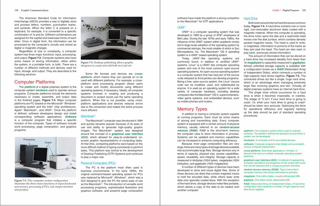
Regardless of size or complexity, a computer system has three major functions: input, processing, and output, Figure 7-2. Computer systems also have some means of storing information, either within the system, in a portable form, or both. There are a number of different methods and devices used for input, storage, and output. They are described in the following sections.
Computer PlatformsThe platform of a digital prepress system is the
computer system hardware used to operate various programs. Computer platforms include the elements necessary to create, assemble, and output data in the fi nished pages, Figure 7-3. Major computer platforms are PC (based on the Microsoft® Windows®
operating system and the Intel® chip architecture), Apple® Macintosh®, and UNIX®. Once the platform is defi ned, software developers design and install corresponding software applications. Softwareis a computer program that initiates a specifi c function of the computer. Types of software include word processing, page composition, and graphics programs.
Some fi le formats and devices are cross-platform, which means they can operate on or be used with different platforms. For example, a cross-platform word processing program allows users to create and modify documents using different operating systems, if necessary. Ideally, all computer systems involved in creating and producing a document or project would use the same operating platform. When this is not possible, using cross-platform applications and devices reduces errors due to fi le conversion and makes the entire process more effi cient.
Macintosh®
The Macintosh® computer was introduced in 1984 and quickly became popular because of its ease of use and ability to generate high-quality graphic images. The Macintosh® system was designed around the concept of a graphical user interface (GUI), which allowed for easy-to-understand, on-screen graphic representations of computing tasks. At that time, competing platforms were based on the more diffi cult method of typing commands to perform tasks. This platform was central to the development of Desktop Publishing (DTP) Systems and continues to play a major role.
Personal Computers (PCs)The PC is the platform most often used in
business environments. In the early 1990s, the original command-based operating system for PCs was replaced by Microsoft® Windows®, which was a GUI designed to give the PC the same ease of use as the Macintosh®. The introduction of versatile word processing programs, sophisticated illustration and graphics software, and powerful page composition
Input
ProcessingOutput
Figure 7-2. This computer system confi guration illustrates the three main functions of input (keyboard and mouse), processing (CPU), and output (monitor and printer).
Figure 7-3. Desktop publishing allows graphic designers to create and edit both text and art.
Chapter 7 Digital Prepress 129
software have made this platform a strong competitor to the Macintosh® for DTP applications.
UNIX®
UNIX® is a computer operating system that was developed in 1969 by a group of AT&T employees at Bell Labs. During the late 1970s and early 1980s, the infl uence of the UNIX® system within academic circles led to large-scale adoption of the operating system by commercial startups, the most notable of which is Sun Microsystems, Inc. The Macintosh® OS X operating system is a UNIX®-based operating system.
Today, UNIX®-like operating systems are commonly found, in addition to certifi ed UNIX®
systems. Linux® is a UNIX®-like computer operating system and one of the most common open-source operating systems. An open-source operating system is a computer system that has had part of the source code released so third parties can develop programs. Being a free, open-source system, the Linux® source code can be modifi ed, used, and redistributed by anyone. It is used as an operating system for a wide variety of computer hardware, including desktop computers like the Macintosh® OS X, supercomputers, video game systems, and embedded devices, such as mobile phones and routers.
Memory TypesIn addition to having a computer system capable
of running programs, there must be some means of storing and transmitting data. Every computer system is equipped with a certain amount of physical memory, usually referred to as random-access memory (RAM). RAM is the short-term memory the computer uses to store information in process. Systems can be updated and memory capabilities can be increased to enhance computing effi ciency.
Because most page composition fi les are very large, there are many types of storage devices available that accommodate large fi les. Storage devices vary in terms of capacity, physical size, access capabilities, speed, reusability, and integrity. Storage capacity is measured in kilobytes (1024 bytes), megabytes (1024 kilobytes), and gigabytes (1024 megabytes).
A number of different types of devices have been developed to store and reuse digital fi les. Some of these devices use disks that contain magnetic tracks to hold the encoded data, while others laser write data onto specially coated discs. With the exception of the hard drive, storage devices make fi les portable, which allows a copy of the data to be loaded onto another computer.
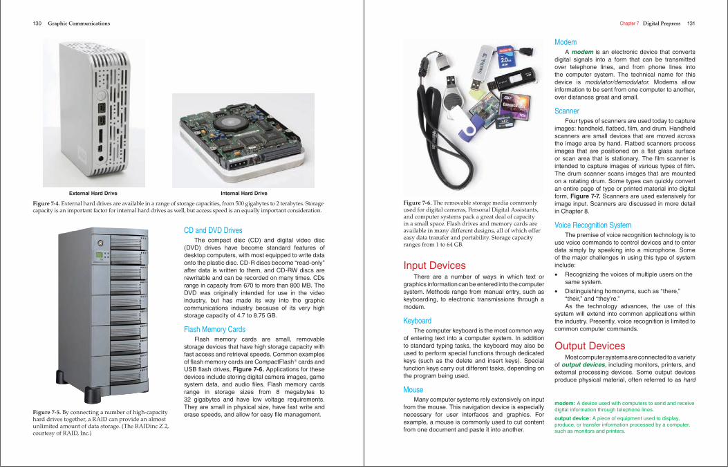
Hard DriveBoth external and internal hard drives are common
today, Figure 7-4. A hard drive contains one or more rigid, non-removable aluminum disks coated with a magnetic material. When the computer is operating, the drive motor spins the disk and a read/write head moves over the disk surface, which contains densely packed magnetic tracks. The head is used to write, or magnetize, information to portions of the tracks as they spin past the head. The head can also read, or play back, previously stored information.
The amount of information that can be stored on a hard drive has increased steadily from fewer than 10 megabytes to capacities measured in gigabytes.Almost unlimited storage capacity is available with a confi guration known as a RAID (Redundant Array of Independent Disks), which connects a number of high-capacity hard drives together, Figure 7-5. The connected drives act like a single, huge hard drive, which is an advantage when managing extremely large fi les involving graphics and text. Virtually all digital prepress systems have an internal hard drive.
The single most critical occurrence for a hard drive is when it becomes inoperable, or crashes. The adage of “It isn’t if your hard drive is going to crash, it’s when your hard drive is going to crash” should be taken very seriously. Optimizing the drive for operational effi ciency and regularly backing up the data should be part of standard operating procedures.
platform: The computer system that is used to operate software. The platform defi nes the standard around which a system can be developed.
hardware: A computer and its associated devices.
software: Computer programs that initiate and accomplish various computer-based tasks.
cross-platform: Describes applications, formats, or devices that work on multiple computer operating system platforms.
graphical user interface (GUI): A method of representing computer operations and programs on the screen with icons that can be selected with a mouse to perform activities.
random-access memory (RAM): Type of short-term computer memory that stores information in process.
megabyte: One million bytes; usually abbreviated MB.
gigabyte: One billion bytes, abbreviated GB.
RAID: Redundant Array of Independent Disks. A hard drive confi guration that connects a number of high-capacity hard disk drives together.
130 Graphic Communications
CD and DVD DrivesThe compact disc (CD) and digital video disc
(DVD) drives have become standard features of desktop computers, with most equipped to write data onto the plastic disc. CD-R discs become “read-only” after data is written to them, and CD-RW discs are rewritable and can be recorded on many times. CDs range in capacity from 670 to more than 800 MB. The DVD was originally intended for use in the video industry, but has made its way into the graphic communications industry because of its very high storage capacity of 4.7 to 8.75 GB.
Flash Memory CardsFlash memory cards are small, removable
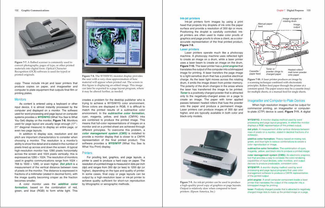
storage devices that have high storage capacity with fast access and retrieval speeds. Common examples of fl ash memory cards are CompactFlash® cards and USB fl ash drives, Figure 7-6. Applications for these devices include storing digital camera images, game system data, and audio fi les. Flash memory cards range in storage sizes from 8 megabytes to 32 gigabytes and have low voltage requirements. They are small in physical size, have fast write and erase speeds, and allow for easy fi le management.
Internal Hard DriveExternal Hard Drive
Figure 7-4. External hard drives are available in a range of storage capacities, from 500 gigabytes to 2 terabytes. Storage capacity is an important factor for internal hard drives as well, but access speed is an equally important consideration.
Figure 7-5. By connecting a number of high-capacity hard drives together, a RAID can provide an almost unlimited amount of data storage. (The RAIDinc Z 2, courtesy of RAID, Inc.)
Chapter 7 Digital Prepress 131
Input DevicesThere are a number of ways in which text or
graphics information can be entered into the computer system. Methods range from manual entry, such as keyboarding, to electronic transmissions through a modem.
KeyboardThe computer keyboard is the most common way
of entering text into a computer system. In addition to standard typing tasks, the keyboard may also be used to perform special functions through dedicated keys (such as the delete and insert keys). Special function keys carry out different tasks, depending on the program being used.
MouseMany computer systems rely extensively on input
from the mouse. This navigation device is especially necessary for user interfaces and graphics. For example, a mouse is commonly used to cut content from one document and paste it into another.
ModemA modem is an electronic device that converts
digital signals into a form that can be transmitted over telephone lines, and from phone lines into the computer system. The technical name for this device is modulator/demodulator. Modems allow information to be sent from one computer to another, over distances great and small.
ScannerFour types of scanners are used today to capture
images: handheld, fl atbed, fi lm, and drum. Handheld scanners are small devices that are moved across the image area by hand. Flatbed scanners process images that are positioned on a fl at glass surface or scan area that is stationary. The fi lm scanner is intended to capture images of various types of fi lm. The drum scanner scans images that are mounted on a rotating drum. Some types can quickly convert an entire page of type or printed material into digital form, Figure 7-7. Scanners are used extensively for image input. Scanners are discussed in more detail in Chapter 8.
Voice Recognition SystemThe premise of voice recognition technology is to
use voice commands to control devices and to enter data simply by speaking into a microphone. Some of the major challenges in using this type of system include:
• Recognizing the voices of multiple users on the same system.
• Distinguishing homonyms, such as “there,” “their,” and “they’re.” As the technology advances, the use of this
system will extend into common applications within the industry. Presently, voice recognition is limited to common computer commands.
Output DevicesMost computer systems are connected to a variety
of output devices, including monitors, printers, and external processing devices. Some output devices produce physical material, often referred to as hard
Figure 7-6. The removable storage media commonly used for digital cameras, Personal Digital Assistants, and computer systems pack a great deal of capacity in a small space. Flash drives and memory cards are available in many different designs, all of which offer easy data transfer and portability. Storage capacity ranges from 1 to 64 GB.
modem: A device used with computers to send and receive digital information through telephone lines.
output device: A piece of equipment used to display, produce, or transfer information processed by a computer, such as monitors and printers.
132 Graphic Communications
copy. These include ink-jet and laser printers that produce copies on paper, and imagesetter and computer to plate equipment that outputs fi nal fi lm or printing plates.
MonitorsAs content is entered using a keyboard or other
input device, it is almost instantly processed by the computer and displayed on a monitor. The software used for word processing and page layout on computer systems provides a WYSIWYG (What You See Is What You Get) display on the monitor, Figure 7-8. Monitors used for page layout are usually large enough (17″–21″ diagonal measure) to display an entire page, or even two page layouts.
In addition to display size, resolution and dot pitch are important characteristics to consider when choosing a monitor. The resolution is a monitor’s ability to show fi ne detail and is stated in the number of pixels lined up across and down the screen. A typical high-resolution monitor has 1280 pixels horizontally across the screen and 1024 pixels vertically; this is expressed as 1280 × 1024. The resolution of monitors used in graphic communications range from 1024 ×768 to 1600 × 1280, or even higher. Dot pitch is a measurement of the vertical distance between rows of pixels on the monitor. The distance is expressed in fractions of a millimeter (stated in decimal form), with the image quality becoming crisper as the fraction becomes smaller.
A color monitor uses the additive color formation, based on the combination of red, green, and blue (RGB) to form white light. This
creates a problem for the desktop publisher who is trying to achieve a WYSIWYG color environment. Since colors are displayed in RGB, it is diffi cult to match the printed results of a subtractive color environment. In the subtractive color formation,cyan, magenta, yellow, and black (CMYK) inks are combined to produce the printed image. This means that full-color representations of images on a monitor and on a printed sheet are achieved through different principles. To overcome this problem, acolor management system (CMS) is installed to provide a monitor display that is closer to a CMYK representation of the fi nal printed product. This software provides a WYSIWYP (What You See Is What You Print) display.
PrintersFor proofi ng text, graphics, and page layouts, a
printer is used to produce a hard copy on paper. The resolution of a printed image is measured in dots per inch (dpi) and ranges from 300 dpi (or less) to 1200 dpi (or higher), depending on the type and quality of printer. In some cases, fi nal copy or page layouts can be output by a high-resolution laser or ink-jet printer to achieve quality suffi cient for short-run reproduction by lithographic or xerographic methods.
Figure 7-7. A fl atbed scanner is commonly used to convert photographs, pages of type, or other printed materials into digital form. Optical Character Recognition (OCR) software is used for typed or printed originals. Figure 7-8. The WYSIWYG monitor display provides
the user with a very close approximation of how material will appear when printed out. The screen in this fi gure is displaying an edited image. This image can later be exported to a page layout program, where it may be altered further, as needed.
Chapter 7 Digital Prepress 133
Ink-jet printersInk-jet printers form images by using a print
head that projects tiny droplets of ink onto the paper surface and provide a resolution of 300 dpi or more. Positioning the droplet is carefully controlled. Ink-jet printers are often used to make color proofs of graphics and page proofs to show a client, as a color-accurate representation of the fi nal printed product, Figure 7-9.
Laser printersLaser printers operate much like a photocopy
machine. A photocopy machine uses refl ected light to create an image on a drum, while a laser printer uses a laser beam to create an image on the drum, Figure 7-10. The laser printer has a print engine that translates the output of the computer into a bitmapped image for printing. A laser transfers the page image to a light-sensitive drum that has a positive electrical charge. As the laser light moves across the rotating drum, it emits the image drawn from printer memory. The polarity of the drum changes in the areas where the laser has transferred the image to be printed. Toner is a positively charged powder that is attracted only to the negatively-charged areas on a page to create an image. The paper with toner applied passes between heated rollers that fuse the powder onto the paper and produce a permanent image. Laser printers can produce images of 300 dpi and higher, and are typically available in both color and black-only models.
Imagesetter and Computer-to-Plate DevicesWhen high-resolution images must be output for
commercial printing, an imagesetter or computer-to-plate (CTP) device is used, Figure 7-11. A digital
Figure 7-9. An ink-jet printer can be used to produce a high-quality proof copy of graphics or page layouts. Output is relatively slow when compared to laser printers. (Epson America, Inc.)
Manual paperfeed
Image charged onrotating drum
Imageoutput
Heated rollersmelt toner powderonto paper
Toner orpowder clings tocharged paper
Cassettepaper feed
Figure 7-10. A laser printer produces an image by a scanning technique combined with electrostatic principles. Rollers feed paper through the printer at a constant speed. The paper source may be a cassette (tray) for multiple sheets, or a manual feed for single sheets.
WYSIWYG: A monitor display method used by word processing and page layout programs, in which the monitor displays a RGB representation of the printed output.
dot pitch: A measurement of the vertical distance between rows of pixels on a monitor, stated in decimal fractions of a millimeter.
additive color formation: Theory based on mixing red, green, and blue light in various combinations to create a color reproduction or image.
subtractive color formation: The combination of cyan, magenta, yellow, and black inks to produce a printed image.
color management system (CMS): An electronic prepress tool that provides a way to correlate the color-rendering capabilities of input devices, color monitors, and output devices to produce predictable, consistent color.
WYSIWYP: A monitor display method used by word processing and page layout programs that uses color management software to produce a CMYK representation of the printed output.
print engine: A small computer component inside a laser printer that translates the output of the computer into a bitmapped image for printing.
toner: Positively charged powder that is attracted to negatively charged image dots to make up the printed image on a page.
134 Graphic Communications
output station consists of two parts, the raster image processor and the digital output device. The digital output device can be used to output high-resolution text and graphic images onto paper, plates, or directly to a digital printing press.
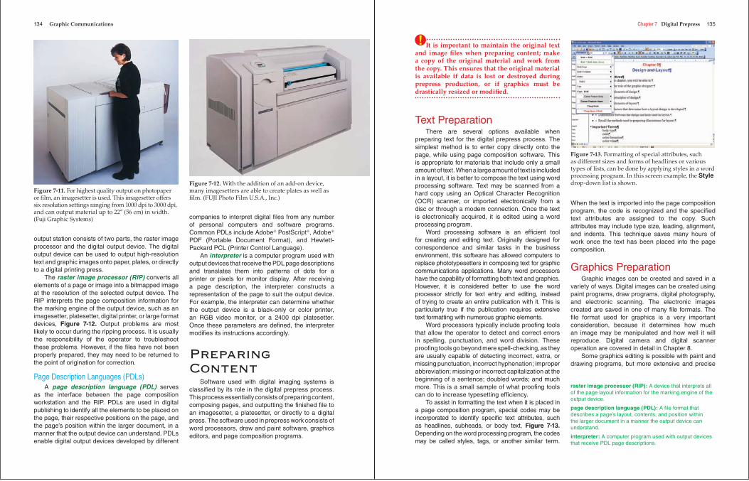
The raster image processor (RIP) converts all elements of a page or image into a bitmapped image at the resolution of the selected output device. The RIP interprets the page composition information for the marking engine of the output device, such as an imagesetter, platesetter, digital printer, or large format devices, Figure 7-12. Output problems are most likely to occur during the ripping process. It is usually the responsibility of the operator to troubleshoot these problems. However, if the fi les have not been properly prepared, they may need to be returned to the point of origination for correction.
Page Description Languages (PDLs)A page description language (PDL) serves
as the interface between the page composition workstation and the RIP. PDLs are used in digital publishing to identify all the elements to be placed on the page, their respective positions on the page, and the page’s position within the larger document, in a manner that the output device can understand. PDLs enable digital output devices developed by different
companies to interpret digital fi les from any number of personal computers and software programs. Common PDLs include Adobe® PostScript®, Adobe®
PDF (Portable Document Format), and Hewlett-Packard PCL (Printer Control Language).
An interpreter is a computer program used with output devices that receive the PDL page descriptions and translates them into patterns of dots for a printer or pixels for monitor display. After receiving a page description, the interpreter constructs a representation of the page to suit the output device. For example, the interpreter can determine whether the output device is a black-only or color printer, an RGB video monitor, or a 2400 dpi platesetter. Once these parameters are defi ned, the interpreter modifi es its instructions accordingly.
Preparing Content
Software used with digital imaging systems is classifi ed by its role in the digital prepress process. This process essentially consists of preparing content, composing pages, and outputting the fi nished fi le to an imagesetter, a platesetter, or directly to a digital press. The software used in prepress work consists of word processors, draw and paint software, graphics editors, and page composition programs.
Figure 7-11. For highest quality output on photopaper or fi lm, an imagesetter is used. This imagesetter offers six resolution settings ranging from 1000 dpi to 3000 dpi, and can output material up to 22″ (56 cm) in width. (Fuji Graphic Systems)
Figure 7-12. With the addition of an add-on device, many imagesetters are able to create plates as well as fi lm. (FUJI Photo Film U.S.A., Inc.)
Chapter 7 Digital Prepress 135
It is important to maintain the original text and image fi les when preparing content; make a copy of the original material and work from the copy. This ensures that the original material is available if data is lost or destroyed during prepress production, or if graphics must be drastically resized or modifi ed.
Text PreparationThere are several options available when
preparing text for the digital prepress process. The simplest method is to enter copy directly onto the page, while using page composition software. This is appropriate for materials that include only a small amount of text. When a large amount of text is included in a layout, it is better to compose the text using word processing software. Text may be scanned from a hard copy using an Optical Character Recognition (OCR) scanner, or imported electronically from a disc or through a modem connection. Once the text is electronically acquired, it is edited using a word processing program.
Word processing software is an effi cient tool for creating and editing text. Originally designed for correspondence and similar tasks in the business environment, this software has allowed computers to replace phototypesetters in composing text for graphic communications applications. Many word processors have the capability of formatting both text and graphics. However, it is considered better to use the word processor strictly for text entry and editing, instead of trying to create an entire publication with it. This is particularly true if the publication requires extensive text formatting with numerous graphic elements.
Word processors typically include proofi ng tools that allow the operator to detect and correct errors in spelling, punctuation, and word division. These proofi ng tools go beyond mere spell-checking, as they are usually capable of detecting incorrect, extra, or missing punctuation, incorrect hyphenation; improper abbreviation; missing or incorrect capitalization at the beginning of a sentence; doubled words; and much more. This is a small sample of what proofi ng tools can do to increase typesetting effi ciency.
To assist in formatting the text when it is placed in a page composition program, special codes may be incorporated to identify specifi c text attributes, such as headlines, subheads, or body text, Figure 7-13.Depending on the word processing program, the codes may be called styles, tags, or another similar term.
When the text is imported into the page composition program, the code is recognized and the specifi ed text attributes are assigned to the copy. Such attributes may include type size, leading, alignment, and indents. This technique saves many hours of work once the text has been placed into the page composition.
Graphics PreparationGraphic images can be created and saved in a
variety of ways. Digital images can be created using paint programs, draw programs, digital photography, and electronic scanning. The electronic images created are saved in one of many fi le formats. The fi le format used for graphics is a very important consideration, because it determines how much an image may be manipulated and how well it will reproduce. Digital camera and digital scanner operation are covered in detail in Chapter 8.
Some graphics editing is possible with paint and drawing programs, but more extensive and precise
!
Figure 7-13. Formatting of special attributes, such as different sizes and forms of headlines or various types of lists, can be done by applying styles in a word processing program. In this screen example, the Styledrop-down list is shown.
raster image processor (RIP): A device that interprets all of the page layout information for the marking engine of the output device.
page description language (PDL): A fi le format that describes a page’s layout, contents, and position within the larger document in a manner the output device can understand.
interpreter: A computer program used with output devices that receive PDL page descriptions.
136 Graphic Communications
changes should be made with a full-featured image manipulation program, or image editor. Some of the most commonly used image manipulation programs include Adobe® Photoshop®, Macromedia® Freehand®
MX, CorelDRAW®, and Adobe® Illustrator®.Full-featured image editors allow almost any
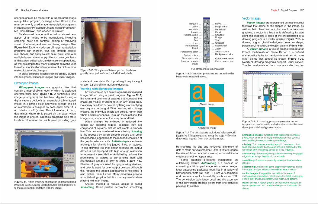
aspect of an image to be manipulated, including cropping, color and contrast, adding or removing visual information, and even combining images. See Figure 7-14. Experienced users of image manipulation programs can sharpen, blur, and smudge edges; mix, choose, and apply colors; paint, draw, work with multiple layers, clone, apply fi lters, create gradients and textures, adjust color, and print color separations, as well as composites. Many programs allow the user to restrict modifi cations to one area of a picture or to make picture-wide changes.
In digital prepress, graphics can be broadly divided into two groups, bitmapped images and vector images.
Bitmapped ImagesBitmapped images are graphics fi les that
contain a map of pixels, each of which is assigned characteristics. See Figure 7-15. A continuous tone image (photograph) that has been digitized using a digital capture device is an example of a bitmapped image. In a simple black-and-white bitmap, one bit of information is assigned to each pixel: either it is on (black) or off (white). This information, in turn, determines where ink is placed on the paper when the image is printed. Graphics programs also store location information for each pixel, providing gray
scale and color data. Each pixel might require eight or even 32 bits of information to describe.
Working with bitmapped imagesArtwork created by a paint program is a bitmapped
image. When using a paint program, Figure 7-16,the rows and columns of squares that compose the image are visible by zooming in on any given area. Color may be added or deleted by fi lling in or emptying each square on the grid. When working with bitmap images, the individual pixels are edited, rather than whole objects or shapes. Through these actions, the image size, shape, or colors may be modifi ed.
When bitmaps are enlarged or reduced, the edges can become ragged because they are composed of squares that do not create a smooth line. This process is referred to as aliasing. Aliasing is the process by which smooth curves and other lines become jagged due to the reduced resolution of the graphics device or fi le. Antialiasing is a software technique for diminishing jagged lines, or jaggies. These stairstep-like lines occur because the output device is not equipped with high enough resolution to represent a smooth line. Antialiasing reduces the prominence of jaggies by surrounding them with intermediate shades of gray or color, Figure 7-17.Shades of gray are used for gray-scaling devices, and color is used for color output devices. Although this reduces the jagged appearance of the lines, it also makes them fuzzier. Many programs provide an antialiasing option that is extremely useful when placing text in an image.
Another method to reduce jaggies is called smoothing. Some printers accomplish smoothing
Figure 7-14. When cropping an image in an image editing program, such as Adobe Photoshop, use the marquee tool to make a selection, and then trim the image.
Figure 7-15. This piece of bitmapped art has been greatly enlarged to show the individual pixels.
Chapter 7 Digital Prepress 137
by changing the size and horizontal alignment of dots to make curves smoother. Other printers reduce the size of those dots that make up a curved line to create a smoother appearance.
Some graphics programs incorporate an autotracing feature. Autotracing is a process for converting a bitmapped image into a vector image. Most autotracing packages read fi les in a variety of bitmapped formats (GIF and TIFF are very common) and produce a vector format fi le, such as an EPS. The conversion techniques used and the accuracy of the conversion process differs from one software package to another.
Vector ImagesVector images are represented as mathematical
formulas that defi ne all the shapes in the image, as well as their placement in a document. In computer graphics, a vector is a line that is defi ned by its start point and endpoint. A piece of line art generated by a drawing program is a vector graphic, Figure 7-18. A drawing program gives the designer control over shape, placement, line width, and object pattern, Figure 7-19.
A Bezier curve is a vector graphic named after French mathematician Pierre Bezier. It is defi ned mathematically by two endpoints and two or more other points that control its shape, Figure 7-20.Nearly all drawing programs support Bezier curves. The two endpoints of the curve are called anchor
Marquee……Lasso……
Airbrush……Eraser……
Rubber stamp……Blur……Pen……Line……
Paint bucket……Hand……
Foreground color……
Default colors……Standard mode……
Standard screen…… mode
……Move……Magic wand……Paintbrush……Pencil……Smudge……Dodge……Type……Gradient……Eyedropper……Zoom……Switch colors……Background color
……Quick mask mode……Full screen mode…
…
Full screen mode with menu bar
Figure 7-16. Most paint programs are limited to the basic tools indicated above.
Aliased Image
Antialiased Image
Figure 7-17. The antialiasing technique helps smooth jaggies by fi lling in squares along the edge with color that varies slightly from that on the image.
Figure 7-18. A drawing program generates vector images that can be easily scaled and modifi ed because the object is defi ned geometrically.
bitmapped images: Graphics fi les that contain a map of pixels, each of which is assigned characteristics such as color and brightness, to make up the image.
aliasing: The process in which smooth curves and other lines become jagged because an image is enlarged or the resolution of the graphics device or fi le is reduced.
antialiasing: Software technique for diminishing the jagged edges of an image that should be smooth.
smoothing: A technique used by some printers to reduce jaggies.
autotracing: A feature of some graphics programs; allows bitmapped images to be converted into vector format.
vector images: Images that are defi ned in terms of mathematical parameters, which gives the artist or designer control over shape, placement, line width, and pattern.
Bezier curve: A vector graphic defi ned mathematically by two endpoints and two or more other points that control its shape.
138 Graphic Communications
points. The other points that defi ne the shape of the curve are called handles, tangent points, or nodes. Attached to each handle are two control points. The shape of the curve can be modifi ed by moving the handles or the control points.
There are several advantages to using vector images:
• Shapes can be resized without degradation because objects are defi ned geometrically.
• The images print the same, even when scaled to different sizes, and can be represented at any resolution, which makes them more fl exible than bitmapped images.
• A computer can store vector images very effi ciently, making them ideal for high-resolution output.
Digital Page Composition
The assembly of text and graphic images into the fi nal page is accomplished using a page composer. The most widely used page composition software packages today are Adobe® InDesign® and QuarkXPress®. Although the specifi c operations are somewhat different, an experienced operator can use either program to combine text and graphics and create a fi le in PostScript®. A PostScript® fi le can be output to a laser printer, platesetter, or even directly to a digital press.
Composition Software Features
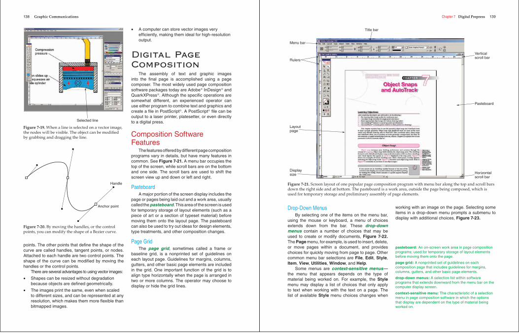
The features offered by different page composition programs vary in details, but have many features in common. See Figure 7-21. A menu bar occupies the top of the screen, while scroll bars are on the bottom and one side. The scroll bars are used to shift the screen view up and down or left and right.
PasteboardA major portion of the screen display includes the
page or pages being laid out and a work area, usually called the pasteboard. This area of the screen is used for temporary storage of layout elements (such as a piece of art or a section of typeset material) before moving them onto the layout page. The pasteboard can also be used to try out ideas for design elements, type treatments, and other composition changes.
Page GridThe page grid, sometimes called a frame or
baseline grid, is a nonprinted set of guidelines on each layout page. Guidelines for margins, columns, gutters, and other basic page elements are included in the grid. One important function of the grid is to align type horizontally when the page is arranged in two or more columns. The operator may choose to display or hide the grid lines.
Selected line
Figure 7-19. When a line is selected on a vector image, the nodes will be visible. The object can be modifi ed by grabbing and dragging the line.
Handle
Anchor point
Figure 7-20. By moving the handles, or the control points, you can modify the shape of a Bezier curve.
Chapter 7 Digital Prepress 139
Drop-Down MenusBy selecting one of the items on the menu bar,
using the mouse or keyboard, a menu of choices extends down from the bar. These drop-down menus contain a number of choices that may be used to create or modify documents, Figure 7-22.The Page menu, for example, is used to insert, delete, or move pages within a document, and provides choices for quickly moving from page to page. Other common menu bar selections are File, Edit, Style,Item, View, Utilities, Window, and Help.
Some menus are context-sensitive menus—the menu that appears depends on the type of material being worked on. For example, the Stylemenu may display a list of choices that only apply to text when working with the text on a page. The list of available Style menu choices changes when
working with an image on the page. Selecting some items in a drop-down menu prompts a submenu to display with additional choices, Figure 7-23.
Menu bar
Title bar
Verticalscroll bar
Horizontalscroll bar
Pasteboard
Rulers
Layoutpage
Displaysize
Figure 7-21. Screen layout of one popular page composition program with menu bar along the top and scroll bars down the right side and at bottom. The pasteboard is a work area, outside the page being composed, which is used for temporary storage and preliminary assembly of page elements.
pasteboard: An on-screen work area in page composition programs; used for temporary storage of layout elements before moving them onto the page.
page grid: A nonprinted set of guidelines on each composition page that includes guidelines for margins, columns, gutters, and other basic page elements.
drop-down menus: A selection list within software programs that extends downward from the menu bar on the computer display screen.
context-sensitive menu: The characteristic of a selection menu in page composition software in which the options that display are dependent on the type of material being worked on.
140 Graphic Communications
Dialog BoxesSelecting an item in a drop-down menu often
opens a dialog box, which permits the operator to input additional information, Figure 7-24. This information may specify an action, input measurements, select colors, or apply a style. Some dialog boxes include drop-down lists, similar to submenus, which can be used to make a selection.
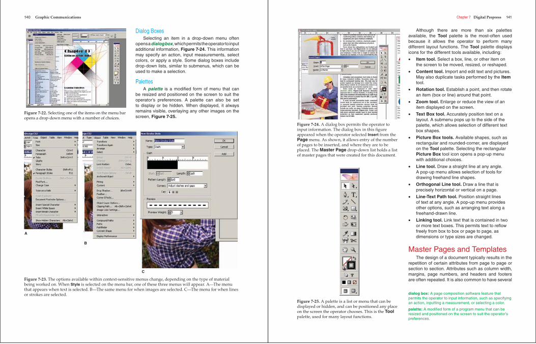
PalettesA palette is a modifi ed form of menu that can
be resized and positioned on the screen to suit the operator’s preferences. A palette can also be set to display or be hidden. When displayed, it always remains visible, overlaying any other images on the screen, Figure 7-25.
Figure 7-22. Selecting one of the items on the menu bar opens a drop-down menu with a number of choices.
A
B
C
Figure 7-23. The options available within context-sensitive menus change, depending on the type of material being worked on. When Style is selected on the menu bar, one of these three menus will appear. A—The menu that appears when text is selected. B—The same menu for when images are selected. C—The menu for when lines or strokes are selected.
Chapter 7 Digital Prepress 141
Although there are more than six palettes available, the Tool palette is the most-often used because it allows the operator to perform many different layout functions. The Tool palette displays icons for the different tools available, including:
• Item tool. Select a box, line, or other item on the screen to be moved, resized, or reshaped.
• Content tool. Import and edit text and pictures. May also duplicate tasks performed by the Itemtool.
• Rotation tool. Establish a point, and then rotate an item (box or line) around that point.
• Zoom tool. Enlarge or reduce the view of an item displayed on the screen.
• Text Box tool. Accurately position text on a layout. A submenu pops up to the side of the palette, which allows selection of different text box shapes.
• Picture Box tools. Available shapes, such as rectangular and rounded-corner, are displayed on the Tool palette. Selecting the rectangular Picture Box tool icon opens a pop-up menu with additional choices.
• Line tool. Draw a straight line at any angle. A pop-up menu allows selection of tools for drawing freehand line shapes.
• Orthogonal Line tool. Draw a line that is precisely horizontal or vertical on a page.
• Line-Text Path tool. Position straight lines of text at any angle. A pop-up menu provides other options, such as arranging text along a freehand-drawn line.
• Linking tool. Link text that is contained in two or more text boxes. This permits text to refl ow freely from box to box or page to page, as dimensions or type sizes are changed.
Master Pages and TemplatesThe design of a document typically results in the
repetition of certain attributes from page to page or section to section. Attributes such as column width, margins, page numbers, and headers and footers are often repeated. It is also common to have several
Figure 7-24. A dialog box permits the operator to input information. The dialog box in this fi gure appeared when the operator selected Insert from the Page menu. As shown, it allows entry of the number of pages to be inserted, and where they are to be placed. The Master Page drop-down list holds a list of master pages that were created for this document.
Figure 7-25. A palette is a list or menu that can be displayed or hidden, and can be positioned any place on the screen the operator chooses. This is the Toolpalette, used for many layout functions.
dialog box: A page composition software feature that permits the operator to input information, such as specifying an action, inputting a measurement, or selecting a color.
palette: A modifi ed form of a program menu that can be resized and positioned on the screen to suit the operator’s preferences.
142 Graphic Communications
different page formats within a document. The page geometry, typography, and other elements in each of these page formats can be set up as a master page, or template.
A template can be created that incorporates all the master pages and other formatting attributes. A new publication or page can easily be set up by opening the reusable template and customizing the page formats, as necessary. The main advantage of using a template is the increased productivity and less time spent recreating the same page information.
Importing TextAlthough text may be directly input and edited
in page composition programs, documents of more than a few paragraphs in length are usually created in a word processing program. The text fi le is then imported into the page composition program and placed in one or more text boxes.
The text formatting (boldface, italics, tabs, indents, line spacing, and similar parameters) that was applied in the original word processing document may be retained when the text is imported if a text fi lter is used. Text fi lters are available for major word processing programs. If no fi lter is available or the imported material is unformatted ASCII text, formatting must be applied through the page composition program.
Style sheets used in page composition programs (and in some word processing programs) are formatting tools that combine a number of attributes. A paragraph style sheet can include such information as alignment, indents, leading between lines, space before and after the paragraph, and such typeface information as font, point size, and kerning. Usually, different paragraph style sheets are created to format specifi c elements of a document, such as body text, main headings, subheadings, numbered lists, lists with bullets, or illustration captions.
A character style sheet is more specialized and is typically applied to single letters, words, or phrases. A character style sheet might be used to set off all illustration references in the text, for example, by specifying a type font and point size that is different from body text. A major advantage of using style sheets is the ability to accomplish changes quickly and thoroughly. For example, changing the attributes of a heading style from centered 18-point Helvetica Bold to fl ush left 16-point Cooper Black takes only seconds, and changing the style would alter every occurrence of that heading in the document.
Importing GraphicsBoth bitmapped graphics created with paint
programs and vector images created with drawing or illustration programs can be imported and placed in a picture box. Photographs are captured with a digital device, such as a camera or scanner, which converts them to a digital format. The digital fi le may then be imported to a picture box.
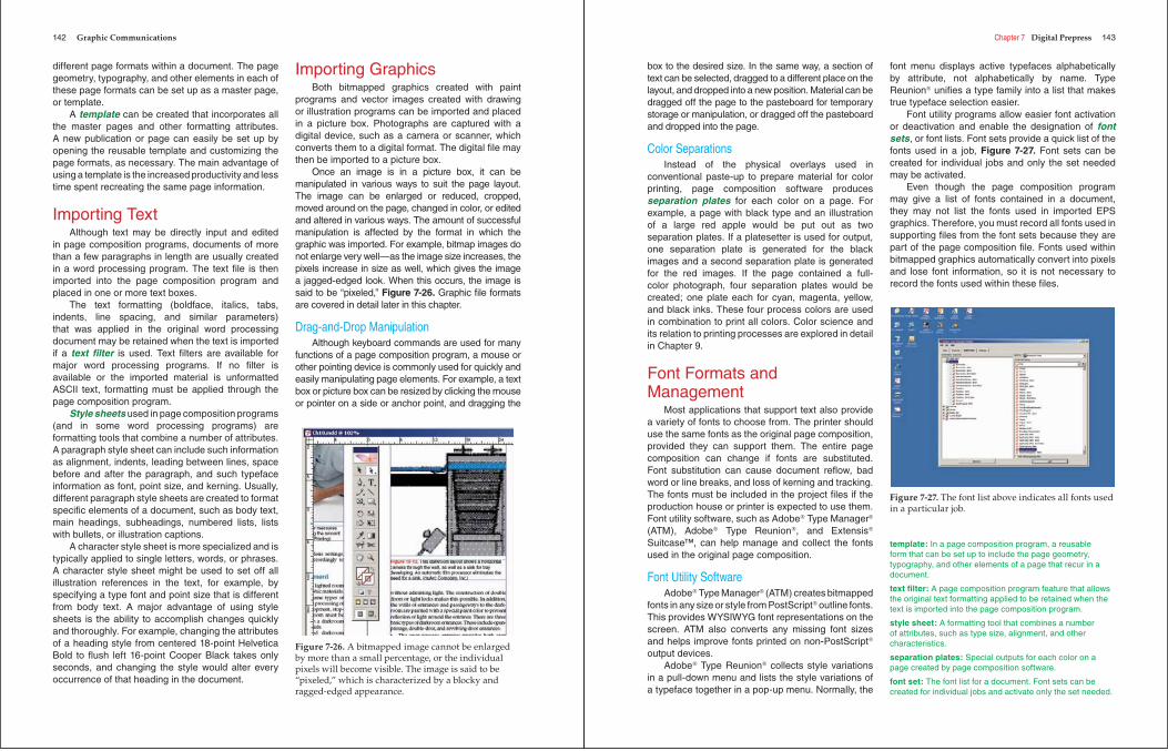
Once an image is in a picture box, it can be manipulated in various ways to suit the page layout. The image can be enlarged or reduced, cropped, moved around on the page, changed in color, or edited and altered in various ways. The amount of successful manipulation is affected by the format in which the graphic was imported. For example, bitmap images do not enlarge very well—as the image size increases, the pixels increase in size as well, which gives the image a jagged-edged look. When this occurs, the image is said to be “pixeled,” Figure 7-26. Graphic fi le formats are covered in detail later in this chapter.
Drag-and-Drop ManipulationAlthough keyboard commands are used for many
functions of a page composition program, a mouse or other pointing device is commonly used for quickly and easily manipulating page elements. For example, a text box or picture box can be resized by clicking the mouse or pointer on a side or anchor point, and dragging the
Figure 7-26. A bitmapped image cannot be enlarged by more than a small percentage, or the individual pixels will become visible. The image is said to be “pixeled,” which is characterized by a blocky and ragged-edged appearance.
Chapter 7 Digital Prepress 143
box to the desired size. In the same way, a section of text can be selected, dragged to a different place on the layout, and dropped into a new position. Material can be dragged off the page to the pasteboard for temporary storage or manipulation, or dragged off the pasteboard and dropped into the page.
Color SeparationsInstead of the physical overlays used in
conventional paste-up to prepare material for color printing, page composition software produces separation plates for each color on a page. For example, a page with black type and an illustration of a large red apple would be put out as two separation plates. If a platesetter is used for output, one separation plate is generated for the black images and a second separation plate is generated for the red images. If the page contained a full-color photograph, four separation plates would be created; one plate each for cyan, magenta, yellow, and black inks. These four process colors are used in combination to print all colors. Color science and its relation to printing processes are explored in detail in Chapter 9.
Font Formats and Management
Most applications that support text also provide a variety of fonts to choose from. The printer should use the same fonts as the original page composition, provided they can support them. The entire page composition can change if fonts are substituted. Font substitution can cause document refl ow, bad word or line breaks, and loss of kerning and tracking. The fonts must be included in the project fi les if the production house or printer is expected to use them. Font utility software, such as Adobe® Type Manager®
(ATM), Adobe® Type Reunion®, and Extensis®
Suitcase™, can help manage and collect the fonts used in the original page composition.
Font Utility SoftwareAdobe® Type Manager® (ATM) creates bitmapped
fonts in any size or style from PostScript® outline fonts. This provides WYSIWYG font representations on the screen. ATM also converts any missing font sizes and helps improve fonts printed on non-PostScript®
output devices.Adobe® Type Reunion® collects style variations
in a pull-down menu and lists the style variations of a typeface together in a pop-up menu. Normally, the
font menu displays active typefaces alphabetically by attribute, not alphabetically by name. Type Reunion® unifi es a type family into a list that makes true typeface selection easier.
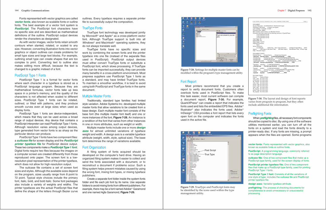
Font utility programs allow easier font activation or deactivation and enable the designation of font sets, or font lists. Font sets provide a quick list of the fonts used in a job, Figure 7-27. Font sets can be created for individual jobs and only the set needed may be activated.
Even though the page composition program may give a list of fonts contained in a document, they may not list the fonts used in imported EPS graphics. Therefore, you must record all fonts used in supporting fi les from the font sets because they are part of the page composition fi le. Fonts used within bitmapped graphics automatically convert into pixels and lose font information, so it is not necessary to record the fonts used within these fi les.
Figure 7-27. The font list above indicates all fonts used in a particular job.
template: In a page composition program, a reusable form that can be set up to include the page geometry, typography, and other elements of a page that recur in a document.
text fi lter: A page composition program feature that allows the original text formatting applied to be retained when the text is imported into the page composition program.
style sheet: A formatting tool that combines a number of attributes, such as type size, alignment, and other characteristics.
separation plates: Special outputs for each color on a page created by page composition software.
font set: The font list for a document. Font sets can be created for individual jobs and activate only the set needed.
144 Graphic Communications
Fonts represented with vector graphics are called vector fonts, also known as scalable fonts or outline fonts. The best example of a vector font system is PostScript. The PostScript font characters have no specifi c size and are described as mathematical defi nitions of the outline. PostScript output devices render the characters as designated.
As with vector images, vector fonts retain smooth contours when slanted, rotated, or scaled to any size. However, converting illustration fonts into vector graphics or object outlines can create problems for small type sizes and large text blocks. For example, outlining small type can create shapes that are too complex to print. Converting text to outline also makes editing more diffi cult, because the text is changed to a graphic instead of a font.
PostScript Type 1 FontsPostScript Type 1 is a format for vector fonts
where each character in a typeface is stored as a PostScript language program. Because they are mathematical formulas, vector fonts take up less space in a printer’s memory, and the quality of the characters is not affected when scaled to different sizes. PostScript Type 1 fonts can be rotated, outlined, or fi lled with patterns, and they produce smooth curves even at large sizes when used as display fonts.
PostScript Type 1 fonts are device-independent, which means that they can be used across a broad range of output devices. Any device that contains a PostScript interpreter can read PostScript Type 1 fonts. Although resolution varies among output devices, type generated from vector fonts is as sharp as the particular device can produce.
PostScript Type 1 fonts have two component fi les: a suitcase fi le for screen display and the PostScript printer typeface fi le for PostScript device output. These two components make a PostScript Type 1 font.Digital fonts require two fi les because the images on a computer screen are created differently from those reproduced onto paper. The screen font is a low-resolution pixel representation of the printer typeface, which does not allow for high-resolution output.
The suitcase fi le contains a set of screen font sizes and styles. Although the available sizes depend on the program, sizes usually range from 8 point to 72 point. Typical style choices include the primary font, italic, bold, and bold italic. Some font packages also include a variety of weights and widths. The printer typefaces are the actual PostScript fi les that defi ne the shape of the letters through Bezier curve
outlines. Every typeface requires a separate printer fi le to successfully output the composition.
TrueType FontsTrueType font technology was developed jointly
by Microsoft® and Apple® as a cross-platform vector font. Although TrueType support is built into all Windows® and Macintosh® operating systems, they do not always translate well.
TrueType fonts have no specifi c sizes and work by combining the screen fonts and the printer typeface into one fi le (instead of the separate fi les used in PostScript). PostScript output devices must either convert TrueType fonts or substitute a PostScript font, which slows processing. If TrueType fonts can be imported successfully, they can provide many benefi ts in a cross-platform environment. Most prepress suppliers use PostScript Type 1 fonts as a standard, and may have limited TrueType fonts. To maintain a smoother workfl ow, it is best to avoid using both PostScript and TrueType fonts in the same document.
Multiple Master FontsTraditionally, standard type families had limited
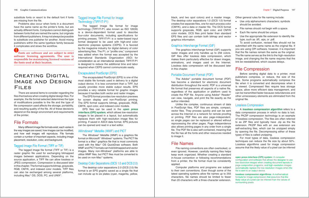
style variation. Adobe Systems Inc. developed multiple master fonts that allow variations to be created from a base design. Each multiple master font consists of the base font (the multiple master font itself) and one or more instances of the font, Figure 7-28. An instance is a rendition of the font that varies from other instances in one or more attributes, such as weight or width.
Multiple master fonts include one or more design axes for almost unlimited variations of typeface weight and width. A design axis is a variable typeface attribute (weight, width, style, optical size). The base font determines the range of variations available.
Font OrganizationA fi ling system of fonts acquired should be
developed on the computer’s hard drive. Having an organized fi ling system makes it easier to collect and send the fonts associated with a document, or to reconstruct a document if problems occur. Such a fi ling system helps prevent mistakes caused by using the wrong font, mixing font types, or mixing typeface publishers.
Create a separate font folder inside the system fonts folder and fi le each job font by its name. Use separate folders to avoid mixing fonts from different publishers. For example, there may be a font named Adobe® Garamond and one named Agfa Garamond, Figure 7-29.
Chapter 7 Digital Prepress 145
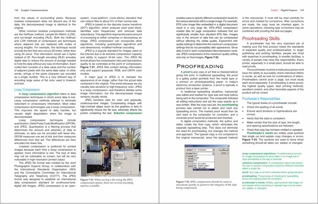
Font ReportMost printers recommend that you create a
report to verify document fonts. Customers often overlook fonts used in PostScript fi les. To make this task easier, most current software can compile a document report, Figure 7-30. For example, QuarkXPress® can create a report that indicates the fonts used and lists the embedded EPS fi les. Adobe®
Illustrator® also indicates the fonts used. Adobe®
InDesign® CS3 provides a font report that lists every open font on the computer and indicates the fonts used in the active fi le.
Prefl ighting FontsWhenprefl ighting fi les, all necessary font components
should be copied to disc. By using one of the software utilities mentioned earlier, you can turn off all the fonts on a system and load the fonts directly to a printer-ready disc. If any fonts are missing, a prompt appears when the fi les are opened. Some programs
Figure 7-28. Settings for multiple master fonts can be modifi ed within the program’s type management utility.
Post Script
True Type
Figure 7-29. TrueType and PostScript fonts may be identifi ed by the icons used within the type management utility.
PAGE 2
DOCUMENTSource Pathname: O:\CATHY\R14A_TX\CH14\Ch14.qxdDestination Pathname: O:\Grph_com\quark\Last modified: 11:03 AM; 11/18/97Document Size: 2884KMost recently saved version: 3.3 Windows formatDocument has been saved by the following versions of QuarkXPress:
3.31r5 Windows format3.32r3 Windows format3.31r5 Windows format
Total Pages: 60Page Width: 8.5”Page Height: 10.875”Required XTensions:
NoneActive XTensions:
Cool Blends; CPSI Fixer; Kern-Track XTension; Immedia Project Menu; JPEGImport; LZW Import; MS-Word Filter; MS-Write Import; WordPerfect Filter; XPress TagsFilter; PhotoCD Import
DOCUMENT FONTSExternal Name Internal Name Printer Font Filename<Helvetica Helvetica-Bold C:\PSFONTS\PFM\HVB_____.PFM<PalmSprings PalmSprings-Bold C:\PSFONTS\PFM\PALMSPRB.PFM<PalmSprings PalmSprings-Normal C:\PSFONTS\PFM\PALMSPRN.PFM<ZapfDingbats SWA ITC-Zapf-Dingbats-SWA C:\PSFONTS\PFM\3030X___.PFM
<Helvetica Helvetica-BoldOblique C:\PSFONTS\PFM\HVBO____.PFM
<Helvetica Helvetica C:\PSFONTS\PFM\HV______.PFM
<PalmSprings PalmSprings-BoldItalic C:\PSFONTS\PFM\PALMSPRT.PFM
<Symbol Symbol C:\PSFONTS\PFM\SY______.PFM<PalmSprings PalmSprings-Italic C:\PSFONTS\PFM\PALMSPRI.PFM<Times Times-Roman C:\PSFONTS\PFM\TIR_____.PFM<Symbol Symbol C:\PSFONTS\PFM\SY______.PFM
PICTURE FONTSPicture External Namenote_c.eps No fonts used.r14opnr.eps No fonts used.00_aug.eps No fonts used.note_c.eps No fonts used.protip_c.eps No fonts used.protip_c.eps No fonts used.note_c.eps No fonts used.00_aug.eps No fonts used.protip_c.eps No fonts used.00_aug.eps No fonts used.
ELECTRONIC OUTPUT REQUEST FOR: YOUR COMPANY NAME HERE
Figure 7-30. The layout and design of font reports varies from program to program, but they often include additional fi le information.
vector fonts: Fonts represented with vector graphics, also known as scalable fonts or outline fonts.
PostScript: A programming language, commonly referred to as page description language.
suitcase fi le: One of two component fi les that make up a PostScript type family, used for the screen display of fonts.
PostScript printer typeface fi le: One of two component fi les that make up a PostScript type family, used for printing PostScript Type 1 fonts.
PostScript Type 1 font: Consists of all the variations of one style of type; includes the suitcase fi le and PostScript printer typeface fi le.
design axes: Variable typeface attribute.
prefl ighting: The process of checking documents for completeness to avoid unnecessary or unsuccessful processing.
146 Graphic Communications
substitute fonts or resort to the default font if fonts are missing from the fi le.
Problems also occur when fonts in a document have the same name as the printer’s fonts, but are actually different fonts. Computers cannot distinguish between fonts that are named the same, but originate from different publishers. It may not always be possible to substitute one publisher for another. Avoid mixing publishers within the same typeface family because it complicates and slows the workfl ow.
Fonts are software and are subject to strict software licensing agreements. The user is responsible for maintaining licensed versions of the fonts used at their location.
Creating Digital Image and Design Files
There are several items to consider regarding the fi les themselves when creating digital design fi les. For example, the fi le format selected determines the type of modifi cations possible to the fi le and the type of fi le compression used affects the storage, portability, and resulting quality of the fi le. All of these decisions depend on the design environment and requirements of the printer.
File FormatsMany different image fi le formats exist; each varies in
the way images are saved, how images can be modifi ed, and how well images will reproduce. File formats contain a number of important aspects, including image placement, resolution, color, and background.
Tagged Image File Format (TIFF or TIF)The tagged image fi le format (TIFF or TIF) is a
raster graphic fi le used for exchanging bitmapped images between applications. Depending on the source application, a TIFF fi le can allow lossless or JPEG compression. Compression is discussed later in this chapter. The format supports bitmap, grayscale, RGB, CMYK, and indexed color models. TIFF fi les can also be exchanged among several platforms, including Mac® OS, DOS, PC, and UNIX®.
Tagged Image File Format for Image Technology (TIFF/IT-P1)
The tagged image fi le format for image technology (TIFF/IT-P1, also known as ISO 12639) is a device-dependent format used to describe four-color documents, including specifi cations for printing presses. TIFF/IT-P1 is a raster-based input format designed to be used with high-end color electronic prepress systems (CEPS). It is favored by the magazine industry for digital delivery of color advertising fi les. The P1, or “profi le one,” component was added when the format was accepted by the International Standards Organization (ISO) for consideration as an international standard. TIFF/IT-P1 is designed to reduce the additional time and labor required when CEPS cannot communicate easily.
Encapsulated PostScript (EPS)The encapsulated PostScript (EPS) is one of the
most stable fi le formats used in delivery to a digital output device. It is less convenient than a TIFF, but usually provides more stable output results. EPS provides a very reliable format for graphic images because it handles both vector and raster images.
The EPS format provides low-resolution previews for screen display and non-PostScript printing. The EPS format supports bitmap, grayscale, RGB, CMYK, spot color, and indexed color models.
EPS fi les can be used in the open press interface (OPI) system, which allows low-resolution images to be placed in a layout, but automatically replaces them with high-resolution image fi les for printing. If saved in ASCII data format, EPS pictures can be opened and read in a text editor.
Windows® Metafi le (WMF) and PICTThe Windows® Metafi le (WMF) is a graphics fi le
format on Microsoft® Windows® systems. The PICT fi le format is a Mac® graphics fi le that is most commonly used with the Mac® OS QuickDraw software. Both WMF and PICT formats can hold bitmapped and vector images. Many non-Windows® platforms are able to utilize WMF fi les, but PICT fi les must be converted to be used on non-Mac® systems.
Desktop Color Separations (DCS 1.0 and DCS 2.0)The desktop color separations 2.0 (DCS 2.0) fi le
format is an EPS graphic saved as a single fi le that can include up to six plates (cyan, magenta, yellow,
!
Chapter 7 Digital Prepress 147
black, and two spot colors) and a master image. The desktop color separations 1.0 (DCS 1.0) format creates fi ve separate fi les, one for each process color (CMYK), and a data or master fi le. The DCS format supports grayscale, RGB, spot color, and CMYK color models. DCS fi les print faster than standard EPS fi les and can contain both bitmap and vector graphics information.
Graphics Interchange Format (GIF)The graphics interchange format (GIF) supports
raster images and only handles up to 256 colors. GIF fi les offer lossless data compression, which makes them particularly effective for drawn images, animations, and images used on the Internet. Lossless data compression will be discussed later in this chapter.
Portable Document Format (PDF)The Adobe® portable document format (PDF)
has become a standard for electronic document distribution throughout the world. PDF is a universal fi le format that preserves all aspects of a native fi le, regardless of the application or platform used to create the PDF fi le. Anyone using Adobe® Reader®
can view, navigate, and print the fi le exactly as the author intended.
Unlike the complex, continuous stream of data in PostScript fi les, PDF fi les are simple, compact, vector fi les. They process quickly and can be sent across the Internet or a network for remote proofi ng or printing. PDF fi les are also page-independent, so single pages can be replaced or altered without reprocessing the other pages. Page independence also allows printing pages in any order from a single fi le. The PDF fi le is also self-contained, meaning that the fi le has all the fonts and other resources needed to image it.
File NamesFile naming conventions are often overlooked, or
even ignored. However, carefully naming fi les helps keep work organized. Whether creating a standard in-house convention or following recommendations from a printer, the fi le format must be consistently applied.
Computer platforms and programs are subject to their own conventions. Even though some of the latest operating systems allow fi le names up to 255 characters, fi le names should be limited to fewer than 20 characters with a three-character extension.
Other general rules for fi le naming include:
• Use only alphanumeric characters; symbols should be avoided.
• File names should not begin with a space.
• Each fi le name should be unique.
• Use the appropriate fi le extension to identify fi le type, such as .tiff, .eps, or .pdf.To avoid confusion, revised fi les should not be
submitted with the same name as the original fi le. If you are using OPI software, however, it is important that the fi le names remain the same as the original. The fi le name serves as the link to the high-resolution image, and changing the fi le name requires that the link be reestablished, which causes delays.
File CompressionBefore sending digital data to a printer, most
publishers compress, or reduce, the size of the fi les. Some programs automatically compress the fi le when it is converted and decompress when it is viewed. Compressed fi les require less storage space, allow more effi cient data management, and can be transmitted faster because redundancies and other unnecessary elements are eliminated from the original fi le.
Lossless CompressionA lossless compression algorithm refers to a
data compression process in which no data is lost. The PKZIP compression technology is an example of lossless compression. The fi les are often referred to as ZIP fi les and typically have .zip as the fi le extension. PKZIP fi les with an .exe extension are self-extracting fi les, which can be unzipped simply by opening the fi le. Decompressing either of these types of fi les is called unzipping.
For most types of data, lossless compression techniques can reduce the fi le size by about 50%. Lossless algorithms used for image compression assume that the likely value of a pixel can be inferred
open press interface (OPI) system: A computer confi guration and software that allows the designer to use low-resolution images when creating document layouts in page composition programs, and high-resolution images automatically replace the low-resolution images when the fi le is sent to an output device.
lossless compression algorithms: A mathematical formula for image compression that assumes that the likely value of a pixel can be inferred from the values of surrounding pixels.
148 Graphic Communications
from the values of surrounding pixels. Because lossless compression does not discard any of the data, the decompressed image is identical to the original.
Other common lossless compression methods are the Huffman method, Lempel-Ziv-Welch (LZW), and run-length encoding (RLE). Both the Huffman and LZW methods of compression are techniques where adjacent bits are replaced with codes of varying lengths. For example, this technique would encode the fact that zero occurs 20 times, rather than using 20 zeros. This information would use 4 bytes instead of 20. Run-length encoding (RLE) encodes digital data to reduce the amount of storage needed to hold the data without any loss of information. Each coded item consists of a data value and the number of adjacent pixels with the same data value. In other words, strings of the same character are encoded as a single number. This is a very effi cient way of encoding large areas of fl at color used in linework and text.
Lossy CompressionA lossy compression algorithm refers to data
compression techniques in which some data is lost. Lossy compression methods attempt to eliminate redundant or unnecessary information. Most video compression technologies use a lossy compression. This improves the speed of data transfer, but causes slight degradation when the image is decompressed.
Lossy compression techniques include quantization, Delta Pulse Code Modifi cation (DPCM), and JPEG. Quantization is a fi ltering process that determines the amount and selection of data to eliminate, so data can be encoded with fewer bits. DPCM measures one set of bits and then measures differences from that set. The differences are then encoded into fewer bits.
Lossless compression is preferred for printed images because each time a lossy compression is applied, more information is lost. The loss of data may not be noticeable on screen, but will be very noticeable in high-resolution printed output.
The JPEG fi le format was created by the Joint Photographic Experts Group, in collaboration with the International Standards Organization (ISO) and the Consultative Committee for International Telegraphy and Telephony (CCITT). The JPEG format was designed to establish an international data compression standard for continuous-tone, digital still images. JPEG compression is an open-
system, cross-platform, cross-device standard that can reduce fi les to about 5% of their normal size.
JPEG is based on the discrete cosine transform (DCT) algorithm, which analyzes each pixel block, identifi es color frequencies, and removes data redundancy. This algorithm requires the same amount of processing to either compress or decompress an image. JPEG compression can incorporate other algorithms, including quantization algorithms and one-dimensional, modifi ed Huffman encoding.
JPEG is a popular standard for images used on the Internet due to its extreme compression capacity and ability to support 24-bit color. The JPEG fi le format allows the compression ratio and reproduction quality to be controlled at the point of compression, Figure 7-31. JPEG fi les contain bitmap information only and support grayscale, RGB, and CMYK color models.
A major goal of JPEG is to maintain the appearance of an image, rather than the actual data contained in the original. This works because we are visually less sensitive to high-frequency color. JPEG is a lossy compression, and therefore deletes some image information, but the decompressed image remains visually whole.
JPEG functions best for color and grayscale, continuous-tone images. Compressing images with high-contrast edges (such as line graphics or text) to signifi cantly reduce the fi le size, adversely affects the portion containing the text. Selective compression
Figure 7-31. When saving a fi le using the JPEG compression option, there are several encoding options available.
Chapter 7 Digital Prepress 149
enables users to specify different compression levels for the various elements within a single image. For example, EPS color image fi les embedded in a digital document result in a very large fi le. EPS-JPEG compression creates fi les for page composition software that are signifi cantly smaller than standard EPS fi les. Images vary in the amount of data that can be compressed without affecting the visible quality. Experiment with quality settings to determine the maximum compression settings that do not perceptibly alter appearance. Since data is lost in each compression/decompression cycle, use JPEG compression at the maximum quality setting and only on fi nal images, Figure 7-32.
ProofreadingA proof is any copy or art that is checked before
going into print. In traditional typesetting, the proof is a galley pulled (printed) from the metal type or a printout on phototypesetting paper. In today’s electronic production systems, a proof is typically a printout from a laser printer.
In traditional typesetting situations, manuscript was edited and marked for type size and style before being sent to the compositor. The compositor followed all editing instructions and set the copy exactly as it was written. After the copy was set, the proofreadingprocess was carried out to detect and mark any typesetting errors. The marked proof would then be sent back to the compositor for correction, and a corrected proof would be produced and checked.
In digital composition methods, the author and editor create the fi nal copy, which eliminates the separate typesetting step. This does not eliminate the need for proofreading, but changes the method and approach. The typeset copy is not compared to the original manuscript, since the typeset material
is the manuscript. It must still be read carefully for errors and marked for corrections. After corrections are made, the copy must be checked again. In some operations, checking type corrections may be combined with proofi ng the laid-out pages.
Proofreading SkillsA proofreader has the very important job of
making sure the fi nal product meets the standards of expected quality and professionalism. In larger publishing and printing facilities, people are hired with expertise in proofreading. In smaller facilities, a variety of people may have this responsibility. Every printer, especially in a small plant, should be able to read proofs.
The proofreader must be a meticulous person and have the ability to accurately check individual letters in words, as well as look for combinations of letters. Proofreaders cannot scan a page, but must study each word separately. If proofreading is done poorly, the highest quality paper, best printing methods, excellent content, and other favorable aspects of the product will be ruined.
Proofreader’s ResponsibilitiesThe typical duties of a proofreader include:
• Check the spelling of all words.
• Ensure word divisions or hyphenations are correct.
• Verify that the style is consistent.
• Make certain that the size of type, line length, and spacing specifi cations are followed.
• Check that copy has not been omitted or repeated.Proofreader’s marks are widely used symbols
that single out and explain copy changes or errors, Figure 7-33. The symbols are used to show when something should be taken out, added, or changed.
Figure 7-32. JPEG compression should be used at maximum quality to preserve the integrity of the data being compressed.
lossy compression algorithms: A mathematical formula for image compression in which data in an image that is least perceptible to the eye is removed.
selective compression: A compression option that allows the user to specify compression levels for different elements within a single fi le.
proof: Any copy or art that is checked before going into print.
proofreading: The process of checking for typesetting errors and marking them for correction.
proofreader’s marks: Widely used symbols that single out and explain when something in typeset copy is to be taken out, added, or changed.
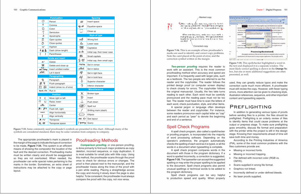
150 Graphic Communications
The appropriate proofreader’s mark is placed in the margin of the page to indicate the type of correction to be made, Figure 7-34. This system is an effi cient means of showing the compositor the location of the fault and the desired correction. Proofreading marks must be written clearly and should be exaggerated so they are not overlooked. When needed, the proofreader can write special notes pertaining to the marks in the border. Sometimes, an extra sheet of instructions may be attached to the copy or page layout.
Proofreading MethodsComparison proofi ng, or one-person proofi ng,
is done primarily to fi nd such major problems as copy deletion, incorrect sequence, or copy duplication. It is most suitable for small jobs with little copy. Using this method, the proofreader scans through the proof once to check for obvious errors or changes. The proof is then placed next to the manuscript, and the proofreader traces along the lines of the proof with a pen while reading. Placing a straightedge across the copy and moving it slowly down the page is also helpful. To be consistent, the proofreader must always compare the proof with the copy, not vice versa.
Period
Comma
Colon
Semicolon
Apostrophe
Open quotes
Close quotes
Hyphen
Dash (show length)
Parentheses
Wrong font
Lower case
Capitalize
Initial cap, then lower case
Small capitals
Initial cap, then small caps
Set in roman
Set in italics
Set in light face
Set in bold face
Superior character
Inferior character
Broken type
Invert
Push down
Spell out
Shilling mark (slash)
Ellipsis
See layout
Query
Delete
Delete and close up
Insert omitted matter
Let it stand
Insert space
Equalize space
Close up
Paragraph
Flush paragraph
Indent (show no. of ems)
Run in
Move right or left
Raise, lower
Center
Flush left, right
Align horizontally
Align vertically
Transpose
Transpose space
Punctuation
Paragraphing
Position
Spacing
Style of type
Miscellaneous
Delete and insert
Figure 7-33. Some commonly used proofreader’s symbols are presented in this chart. Although many of the symbols are considered standard, there may be some variation from company to company.
Chapter 7 Digital Prepress 151
Two-person proofi ng requires the reader to work with an assistant. This is the most common proofreading method when accuracy and speed are important. It is frequently used with larger jobs, such as a textbook. The two people are referred to as the reader and the copyholder. The reader follows the printed design proof (or computer screen display) to check closely for errors. The copyholder follows the original manuscript. Usually, the two take turns reading to each other. Each word must be carefully pronounced and the reading pace must not be too fast. The reader must have time to scan the letters of each word, check punctuation, style, and other items.
A special jargon or language often develops between the reader and copyholder. For instance, some readers pronounce each capital letter as “cap” and each period as “peer” to denote the beginning and end of a sentence.
Spell Check Programs A spell check program, also called a spellchecker
or proofi ng program, is incorporated into the majority of word processing software. Depending on the operator’s preference, the program automatically checks the spelling of each word as it is typed, or all the words in a document when typesetting is complete.
A spell check program compares words in the document with those in the program dictionary. If a word is spelled incorrectly, a correction is suggested, Figure 7-35. The typesetter can accept the suggested spelling or may enter the proper spelling to be applied to the document. Spell check programs also permit unusual spellings or technical words to be added to the program dictionary.
Spell check programs can be very helpful to production speed and quality. When properly
used, they can greatly reduce typos and make the correction cycle much more effi cient. A proofreader must still review the copy. However, with fewer typing errors, more attention can be given to checking style, illustration references, sequence, and other important content and typesetting aspects.
Prefl ightingIn addition to generating various types of proofs
before sending fi les to a printer, the fi les should be prefl ighted. Prefl ighting is an orderly review of fi les to identify items that could cause problems at the output or prepress stage. To make sure prefl ighting goes smoothly, discuss fi le format and preparation with the printer while the project is still in the design stage. Knowing their requirements ahead of time will save both time and money.
According to the Printing Industries of America (PIA), some of the most common problems with the fi les customers provide are:
• Missing or incorrect fonts.
• Missing or incorrect trapping.
• File defi ned with incorrect color (RGB vs. CMYK).
• Scans supplied in wrong fi le format.
• Graphics not linked.
• Incorrectly defi ned or under defi ned bleeds.
• No laser proofs supplied.
Marked copy
Corrected copy
Figure 7-34. This is an example of how proofreader’s marks are used to identify and correct copy problems. Note the caret placed at the point of error, and the correction symbol written in the margin.
Figure 7-35. This spellchecker highlighted a word in the text and displayed it in a separate window. The most likely correct spelling is shown in the Change To:box, but one or more additional suggestions are often presented, as well.
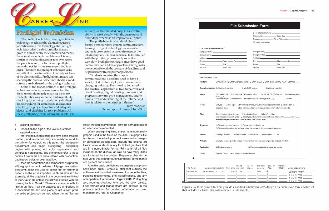
• Missing graphics.
• Resolution too high or too low in customer-supplied scans.After the documents or pages have been created,
proofed, and corrected, they are ready to send to the printer for output. At this point, the production department can begin prefl ighting. Prefl ighting begins with printing out color separations and composite hard copies. The printer can refer to these copies if problems are encountered with production, pagination, color, or even text fl ow.
Once the separations and composites are printed, all the graphics should be linked. All page composition programs allow the user to select link or reference options as the art is imported. In QuarkXPress®, for example, all the graphics in the document are linked to the Quark® fi le unless the art was created with the drawing tools in Quark®. There are many benefi ts to linking art fi les. If all the graphics are embedded in a document fi le and one piece of art is corrupted, the entire project can be lost. When the art fi les are
linked instead of embedded, only the corrupt piece of art needs to be recreated.
When prefl ighting fi les, check to ensure every graphic used in the fi le is on the disc. If a graphic fi le is missing, the art will print as low-resolution images or bitmapped placeholders. Include the original art fi les in a separate directory for linked graphics that are in a non-editable format. Print a list of all fi les included on the disc(s), as well as how many discs are included for the project. Prepare a checklist to help verify that all graphic, font, and color components are present and correct.
After the basic prefl ighting is complete and proofs have been output, create a letter that outlines the software and fonts that were used to create the fi les, trapping requirements, print specifi cations, and any other pertinent information, Figure 7-36. Prefl ighting also requires checking fonts and the color palette. Font formats and management are covered in the previous section. For detailed information on color management, refer to Chapter 10.
C Lareer ink
Preflight TechnicianPrefl ight TechnicianThe prefl ight technician uses digital imaging
technology to achieve the planned requested job. When using this technology, the prefl ight technician takes the electronic fi les that are given to him or her by the customer and checks them for all aspects of completeness. It is very similar to the checklist a pilot goes over before the plane takes off; the formalized prefl ight manual checklist makes sure everything is in order. Therefore, the prefl ight technician tasks are critical to the elimination of output problems of the electronic fi les. Prefl ighting software can speed up the process. Sometimes checklists and software are both used by the prefl ight technician.
Some of the responsibilities of the prefl ight technician include making sure submitted discs are not damaged; ensuring discs are readable; checking in-house font availability; checking for missing material on submitted discs; checking for correct size indications; checking for proper trapping and adequate bleeds; and checking for font problems, All these prefl ighting tasks ensure the digital job
is ready for the intended output device. The ability to work closely with the customer and other departments is an imperative attribute.
The prefl ight technician should have formal postsecondary graphic communications training in digital technology; an associate degree is often stated as a requirement in the job description. It is also benefi cial to be familiar with the printing process and production workfl ow. Prefl ight technicians must have good communication and basic problem-solving skills, be comfortable with the pressure of deadlines, and be profi cient with computer applications.
“Students entering the graphic communications discipline need to have a variety of skills for employment in our ever-changing industry. They need to be versed in the practical application of traditional web and offset printing, digital printing, prepress and prepress software, print management, and to have a fi rm understanding of the Internet and how it relates to the printing industry.”
Tony MancusoTypography Unlimited, Inc. (TUI)
152 Chapter 7 Digital Prepress 153
Bleed No. of Hal f tone Neg. or RREU orFi le Name Appl icat ion/version Tr im size amount pages screen Pos. RRED Color separat ions
C M Y K/ PMS
C M Y K/ PMS
C M Y K/ PMS
C M Y K/ PMS
Chapter 01 QuarkXPress 3 .31 8 .5x11 1/8in . 16 133 Neg RRED 467
B
Book title/Part number
Order date Blues date
Press date Bill to P.O. number
Sales representative
Design house
Design contact
Address
City State Zip
Phone Fax
Modem Baud rate
Company name
Contact name
Address
City State Zip
Phone Fax
Modem Baud rate
CUSTOMER INFORMATION
FILE INFORMATION
Platform ❑ Macintosh ❑ IBM-PC (or compatible) ❑ UNIX (DEC) ❑ UNIX (Sun) ❑ VMS (VAX) ❑ Other ____
Operating system ❑ Macintosh version _____ ❑ MS-DOS version _____ ❑ Windows version _____
Media ❑ 3.5 inch disk ❑ 5.25 inch disk ❑ SyQuest (size___) ❑ 150 Mb DC (QIC tape) ❑ Bernoulli cartridge (size___)
❑ Zip cartridge ❑ Jaz cartridge ❑ Magneto-optical cartridge (size___) ❑ CD-ROM
Fonts ❑ Type 1 ❑ TrueType ❑ Complete font list, including manufacturer names, is attached on a
separate sheet ❑ All printer and screen fonts are included on submission media
Files Files listed on other side are: ❑ Application files ❑ PostScript files Are files compressed? ❑ No ❑ Yes (if yes, what compression software was used?_______version___) Please complete the file list on the other side of this form.
Trapping ❑ Files do not need trapping ❑ Please trap the files for us
❑ Files need trapping, but we have taken the responsibility and done it ourselves
Proofs ❑ Single blueline ❑ Folded blueline ❑ Blackprint ❑ Matchprint ❑ Iris
Artwork ❑ Digital scanning (to be placed in file) ❑ Conventional scanning (to be stripped into film)
Pagination ❑ Total page count _________ ❑ Page map included on separate sheets
Other Special instructions attached on separate sheet
File Submission Form
A
Figure 7-36. If the printer does not provide a standard submission form, design a fi le submission form and fi le list that includes the basic information shown in this sample.
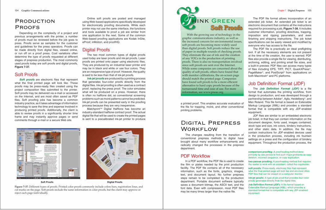
154 Graphic Communications
Production Proofs
Depending on the complexity of a project and previous arrangements with the printer, a number of proofs must be reviewed before the job goes to press. Proofs serve as samples for the customer and guidelines for the press operators. Proofs can be made directly from digital fi les, viewed online, or run off on a proof press. Cost variations often determine the type of proofs requested at different stages of prepress production. The most commonly used proofs today are soft proofs and digital proofs, Figure 7-37.
Soft ProofsSoft proofs are electronic fi les that represent
what the fi nal printed page will look like. These proofs may be press-ready fi les created using the project composition fi les submitted to the printer. Soft proofs may be delivered via e-mail or accessed on the Internet, and are most often saved as PDF fi les. Soft proofi ng jobs has become a common industry practice, as it takes advantage of information technology to save the time and expense involved in producing printed proofs. Additionally, the client is able to review proofs in a signifi cantly shorter time frame and may instantly approve pages or send comments through e-mail or a secure Web site.
Online soft proofs are posted and managed using Web-based applications specifi cally developed for electronically proofi ng documents. While each printer may not use the same interface, the functions and tools available to proof a job are similar from one application to the next. Some of the common Web-based proofi ng applications are Kodak InSite, eProof, inMotion, and proofHQ.
Digital ProofsThe two most common types of digital proofs
used today are laser proofs and ink-jet proofs. Laser proofs are printed onto paper using electronic fi les. They are produced by an industrial laser printer and may be in black and white or use four colors. They are an inexpensive type of proof. However, the quality is said to be less than that of ink-jet proofs.
Ink-jet proofs are produced by a printing process that generates four-color proofs directly from the digital fi les. Ink-jet proofi ng is often used as a contract proof, replacing the press proof. The color simulates what will be produced on a press. However, there is often no halftone dot, so conventional screening problems such as moiré patterns cannot be predicted. Ink-jet proofs can be presented early in the proofi ng process because they are very inexpensive.
Matchprint™ Digital Halftone has become an industry-standard halftone contract proof. The actual digital fi le that will be used to create the printed pages is sent to a precalibrated ink-jet printer to produce
Soft Proofs Digital Proofs
Figure 7-37. Different types of proofs. Printed color proofs commonly include colors bars, registration lines, and cut marks on the page. Soft proofs include the same information in color proofs, but the client may approve or reject each page individually.
Chapter 7 Digital Prepress 155
a printed proof. This enables accurate evaluation of the fi le for trapping, moiré, and other conventional printing problems.
Digital Prepress Workfl ow
The changes resulting from the transition of conventional prepress methods to digital have brought about many workfl ow enhancements and radically changed the processes in the prepress department.
PDF Workfl owIn a PDF workfl ow, the PDF fi le is used to create
the fi lm or plates needed by the print production facility. The PDF fi le contains all of the necessary information, such as the fonts, graphics, images, text, and document layout. No further prepress steps remain to be completed by the production department. Portable document software typically saves a document bitmap, the ASCII text, and the font data. Even with compression, most PDF fi les may be many times larger than the native fi le.
The PDF fi le format allows incorporation of an extended job ticket. An extended job ticket is an electronic document that contains all the instructions required for processing a job, Figure 7-38. It includes customer information, proofi ng directives, trapping, imposition and ripping parameters, and even fi nishing and shipping instructions. The job ticket specifi cations can be easily viewed and modifi ed by everyone who has access to the fi le.
The PDF fi le is practically an ideal prefl ighting tool. If all the necessary elements are not present at the time of fi le creation, the user is warned. PDF fi les also provide a single fi le for viewing, distributing, archiving, editing, and printing small fi le sizes, and a built-in preview. PDF fi les can access many types of fi les including EPS, TIFF, PICT, QuarkXPress®,PageMaker®, and PostScript® from applications on both Macintosh® and PC platforms.
Job Defi nition Format (JDF) The Job Defi nition Format (JDF) is a fi le
format that automates the printing workfl ow, from design to production, and was developed through a partnership between Adobe®, Agfa, Heidelberg®, and Man Roland. This fi le format is based on Extensible Markup Language (XML) and provides a standard format that is compatible with any JDF-enabled equipment.
JDF fi les are similar to an embedded electronic job ticket, in that they can contain information on the document designer, fonts used, images contained, stock type and size, ink colors, bindery instructions, and other static data. In addition, the fi le may contain instructions for JDF-enabled devices used in the production process, including ink fountain settings on a press and the confi guration of bindery equipment. Throughout the production process, the
With the growing use of technology in the graphic communications industry, as well as the increased concern for environmental issues, soft proofs are becoming more widely used than digital proofs. Soft proofs reduce the use of paper in multiple rounds of checking proofs. They eliminate the use of ink and the creation of any VOCs in the production of printing proofs. There is also no transportation involved since soft proofs are sent over the Internet. While some companies are concerned about the quality of soft proofs, others have found that with monitor calibrations, the on-screen page should match the printed page. Companies have found soft proofs to be a more effi cient alternative to hard copy proofs because of the turnaround time and ease of use. For more information, see www.pneac.org.
❦Think GreenSoft ProofsSoft Proofs
comparison proofi ng: A proofreading method done primarily by one person to fi nd such major problems as copy deletion, incorrect sequence, or copy duplication.
two-person proofi ng: A proofreading method that requires the reader to work with an assistant, called the copyholder.
soft proofs: Press-ready, electronic fi les that represent what the fi nal printed page will look like and are most often PDF fi les that can be viewed on a computer monitor.
ink-jet proofs: A type of job proof that provides four-color proofs generated directly from the digital fi les.
Job Defi nition Format (JDF): A fi le format based on Extensible Markup Language (XML), which provides a standard format that is compatible with any JDF-enabled equipment.
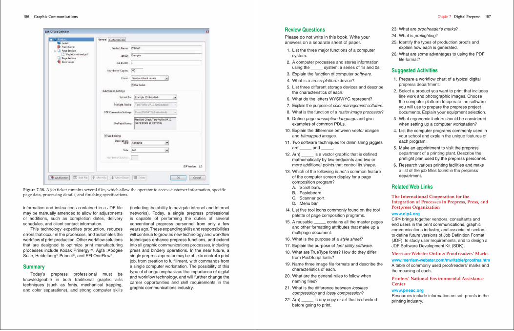
156 Graphic Communications
information and instructions contained in a JDF fi le may be manually amended to allow for adjustments or additions, such as completion dates, delivery schedules, and client contact information.
This technology expedites production, reduces errors that occur in the processes, and automates the workfl ow of print production. Other workfl ow solutions that are designed to optimize print manufacturing processes include Kodak Prinergy™, Agfa :Apogee Suite, Heidelberg® Prinect®, and EFI OneFlow®.
SummaryToday’s prepress professional must be
knowledgeable in both traditional graphic arts techniques (such as fonts, mechanical trapping, and color separations), and strong computer skills
(including the ability to navigate intranet and Internet networks). Today, a single prepress professional is capable of performing the duties of several conventional prepress personnel from only a few years ago. These expanding skills and responsibilities will continue to grow as new technology and workfl ow techniques enhance prepress functions, and extend into all graphic communications processes, including press and bindery operations. In the near future, a single prepress operator may be able to control a print job, from creation to fulfi llment, with commands from a single computer workstation. The possibility of this type of change emphasizes the importance of digital and workfl ow technology, and will further change the career opportunities and skill requirements in the graphic communications industry.
Figure 7-38. A job ticket contains several fi les, which allow the operator to access customer information, specifi c page data, processing details, and fi nishing specifi cations.
Chapter 7 Digital Prepress 157
Review QuestionsPlease do not write in this book. Write your answers on a separate sheet of paper.
1. List the three major functions of a computer system.
2. A computer processes and stores information using the _____ system: a series of 1s and 0s.
3. Explain the function of computer software.
4. What is a cross-platform device?
5. List three different storage devices and describe the characteristics of each.
6. What do the letters WYSIWYG represent?
7. Explain the purpose of color management software.
8. What is the function of a raster image processor?
9. Defi ne page description language and give examples of common PDLs.
10. Explain the difference between vector imagesand bitmapped images.
11. Two software techniques for diminishing jaggies are _____ and _____.
12. A(n) _____ is a vector graphic that is defi ned mathematically by two endpoints and two or more additional points that control its shape.
13. Which of the following is not a common feature of the computer screen display for a page composition program?A. Scroll bars.B. Pasteboard.C. Scanner port.D. Menu bar.
14. List fi ve tool icons commonly found on the tool palette of page composition programs.
15. A reusable _____ contains all the master pages and other formatting attributes that make up a multipage document.
16. What is the purpose of a style sheet?
17. Explain the purpose of font utility software.
18. What are TrueType fonts? How do they differ from PostScript fonts?
19. Name three image fi le formats and describe the characteristics of each.
20. What are the general rules to follow when naming fi les?
21. What is the difference between losslesscompression and lossy compression?
22. A(n) _____ is any copy or art that is checked before going to print.
23. What are proofreader’s marks?
24. What is prefl ighting?
25. Identify the types of production proofs and explain how each is generated.
26. What are some advantages to using the PDF fi le format?
Suggested Activities 1. Prepare a workfl ow chart of a typical digital
prepress department.
2. Select a product you want to print that includes line work and photographic images. Choose the computer platform to operate the software you will use to prepare the prepress project documents. Explain your equipment selection.
3. What ergonomic factors should be considered when setting up a computer workstation?
4. List the computer programs commonly used in your school and explain the unique features of each program.
5. Make an appointment to visit the prepress department of a printing plant. Describe the prefl ight plan used by the prepress personnel.
6. Research various printing facilities and make a list of the job titles found in the prepress department.
Related Web Links
The International Cooperation for the Integration of Processes in Prepress, Press, and Postpress Organizationwww.cip4.orgCIP4 brings together vendors, consultants and end users in the print communications, graphic communications industry, and associated sectors to defi ne future versions of Job Defi nition Format (JDF), to study user requirements, and to design a JDF Software Development Kit (SDK).
Merriam-Webster Online: Proofreaders’ Markswww.merriam-webster.com/mw/table/proofrea.htmA table of commonly used proofreaders’ marks and the meaning of each.
Printers’ National Environmental Assistance Centerwww.pneac.orgResources include information on soft proofs in the printing industry.