graph unification and tangram hypothesis … · graph unification and tangram hypothesis...
TRANSCRIPT

AFRL-RI-RS-TR-2008-228 Final Technical Report August 2008 GRAPH UNIFICATION AND TANGRAM HYPOTHESIS EXPLANATION REPRESENTATION (GATHER) AND SYSTEM AND COMPONENT MODELING FRAMEWORK (SCMF) 21st Century Technologies, Inc.
APPROVED FOR PUBLIC RELEASE; DISTRIBUTION UNLIMITED.
STINFO COPY
AIR FORCE RESEARCH LABORATORY INFORMATION DIRECTORATE
ROME RESEARCH SITE ROME, NEW YORK

NOTICE AND SIGNATURE PAGE Using Government drawings, specifications, or other data included in this document for any purpose other than Government procurement does not in any way obligate the U.S. Government. The fact that the Government formulated or supplied the drawings, specifications, or other data does not license the holder or any other person or corporation; or convey any rights or permission to manufacture, use, or sell any patented invention that may relate to them. This report was cleared for public release by the Air Force Research Laboratory Public Affairs Office and is available to the general public, including foreign nationals. Copies may be obtained from the Defense Technical Information Center (DTIC) (http://www.dtic.mil). AFRL-RI-RS-TR-2008-228 HAS BEEN REVIEWED AND IS APPROVED FOR PUBLICATION IN ACCORDANCE WITH ASSIGNED DISTRIBUTION STATEMENT. FOR THE DIRECTOR: /s/ /s/ DEBORAH A. CERINO JOSEPH CAMERA, Chief Work Unit Manager Information & Intelligence Exploitation Division Information Directorate This report is published in the interest of scientific and technical information exchange, and its publication does not constitute the Government’s approval or disapproval of its ideas or findings.
REPORT DOCUMENTATION PAGE Form Approved OMB No. 0704-0188
Public reporting burden for this collection of information is estimated to average 1 hour per response, including the time for reviewing instructions, searching data sources, gathering and maintaining the data needed, and completing and reviewing the collection of information. Send comments regarding this burden estimate or any other aspect of this collection of information, including suggestions for reducing this burden to Washington Headquarters Service, Directorate for Information Operations and Reports, 1215 Jefferson Davis Highway, Suite 1204, Arlington, VA 22202-4302, and to the Office of Management and Budget, Paperwork Reduction Project (0704-0188) Washington, DC 20503. PLEASE DO NOT RETURN YOUR FORM TO THE ABOVE ADDRESS.1. REPORT DATE (DD-MM-YYYY)
AUG 2008 2. REPORT TYPE
Final 3. DATES COVERED (From - To)
SEP 06 – SEP 08 4. TITLE AND SUBTITLE GRAPH UNIFICATION AND TANGRAM HYPOTHESIS EXPLANATION REPRESENTATION (GATHER) AND SYSTEM AND COMPONENT MODELING FRAMEWORK (SCMF)
5a. CONTRACT NUMBER FA8750-06-C-0209
5b. GRANT NUMBER
5c. PROGRAM ELEMENT NUMBER31011G
6. AUTHOR(S) Jeff Kudrick
5d. PROJECT NUMBER TNGR
5e. TASK NUMBER 00
5f. WORK UNIT NUMBER 04
7. PERFORMING ORGANIZATION NAME(S) AND ADDRESS(ES)21st Century Technologies, Inc. 4515 Seton Center Pkwy, Suite 320 Austin, TX 78759-5731
8. PERFORMING ORGANIZATION REPORT NUMBER N/A
9. SPONSORING/MONITORING AGENCY NAME(S) AND ADDRESS(ES) AFRL/RIED 525 Brooks Rd Rome NY 13441-4505
10. SPONSOR/MONITOR'S ACRONYM(S)N/A
11. SPONSORING/MONITORING AGENCY REPORT NUMBER AFRL-RI-RS-TR-2008-228
12. DISTRIBUTION AVAILABILITY STATEMENT APPROVED FOR PUBLIC RELEASE; DISTRIBUTION UNLIMITED. PA# WPAFB 08-4995
13. SUPPLEMENTARY NOTES
14. ABSTRACT The effort addresses the issues involved in developing a common graph representation for sharing data between counter-terrorism (threat detection) algorithms and communication results from/to each algorithm. These types of algorithms all use graph representation but each algorithm’s underlying representation is slightly different so chaining together algorithms is not straight-forward. The Graph unification challenge is to provide a wrapper where the wrapper converts between the common graph data representation and the native formats required by the algorithms.
15. SUBJECT TERMS Common graph data representation, graph unification, common language representation
16. SECURITY CLASSIFICATION OF: 17. LIMITATION OF ABSTRACT
UU
18. NUMBER OF PAGES
37
19a. NAME OF RESPONSIBLE PERSON Deborah A. Cerino
a. REPORT U
b. ABSTRACT U
c. THIS PAGE U
19b. TELEPHONE NUMBER (Include area code) N/A
Standard Form 298 (Rev. 8-98) Prescribed by ANSI Std. Z39.18

i
TABLE OF CONTENTS Table of Contents ........................................................................................................................................... i List of Figures ............................................................................................................................................... ii List of Tables ................................................................................................................................................ ii 1 Summary ............................................................................................................................................... 1 2 Introduction ........................................................................................................................................... 2 3 Methods, Assumptions, and Procedures ............................................................................................... 6 4 Results & Discussion .......................................................................................................................... 13 5 Contract Artifacts ................................................................................................................................ 28 6 Conclusions ......................................................................................................................................... 29 7 Glossary of Terms, Abbreviations, and Acronyms ............................................................................. 31

ii
LIST OF FIGURES Figure 1: Tangram High Level Architecture ................................................................................................. 2 Figure 2: Graph Unification Problem ........................................................................................................... 3 Figure 3: Graph Unification Solution ........................................................................................................... 3 Figure 4: Tangram Sequence Diagram ......................................................................................................... 6 Figure 5: TanGrid Software .......................................................................................................................... 8 Figure 6: GATHER Framework ................................................................................................................... 9 Figure 7: SR-12 Workflow Template ......................................................................................................... 11
LIST OF TABLES Table 1: Reports Submitted by 21CT in Fulfillment of Contract Artifacts ................................................ 28

1
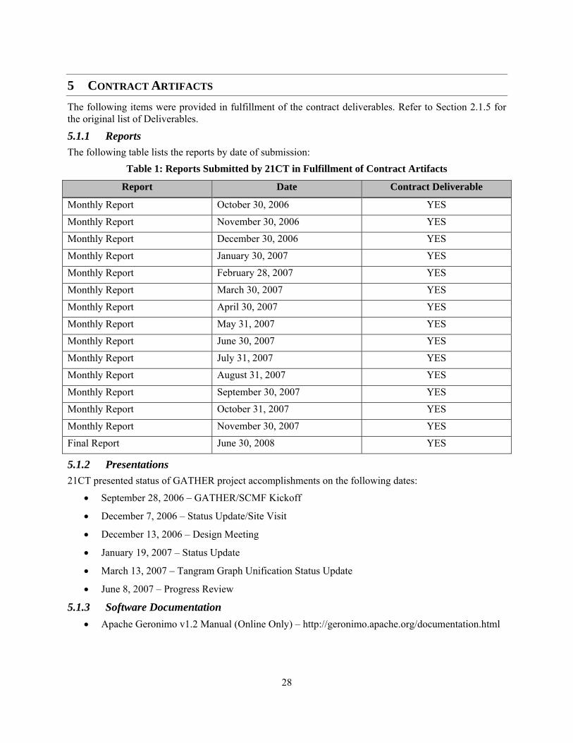
1 SUMMARY 21st Century Technologies (21CT) was contracted by Air Force Research Laboratory (AFRL) to define and develop an inter-component hypothesis exchange specification, a common graph representation specification, a visualization and edit tool, and a methodology for modeling component algorithms to support the AFRL Tangram (a counter terrorism surveillance and warning system) Program overall objectives and architecture. The Graph Unification and Tangram Hypothesis Explanation Representation (GATHER) tasks consisted of the following high-level contract objectives:
1. deliver the Hypothesis Representation Requirements
2. deliver a Hypothesis Representation Specification
3. deliver a Common Graph Representation Specification
4. deliver a Common Graph Edit, Visualization, & Annotation (EVA) Specification
During the course of the project, funding and effort re-scopes reduced the contribution of 21CT down to deliver only the Common Graph Representation Specification and its related tasks. Of this effort, the following was delivered to achieve the System Research (SR) milestones SR-6 and SR-12 program deliverables:
1. IET data transformed into Graph Normal Form (GNF) graph representation
2. GATHER component framework
3. GATHER components:
a. TMODS Best Friends – Group Detection component using a clustering algorithm created at 21st Century Technology.
b. TMODS Pattern Matcher – Pattern Matching component using a graph matching algorithm created at 21st Century Technology.
c. GDA – Group Detection component using a clustering algorithm created at Auton Lab, Carnegie Mellon University.
d. Kojak – Link Discovery software from Information Sciences Institute (ISI), University of Southern California (USC). The initial effort used the Kojak Group Finder.
e. CADRE – Pattern Matching component from BAE Systems. Realized with the help from BAE Systems.
f. LAW – Pattern Matching component from SRI International. Realized with the help from SRI International.
g. Data Merge-Union – Transformational component used to merge data from other components into a single dataset. Realized with the help of Booz Allen Hamilton.
Using the above deliverables from GATHER and the other members of the team, Tangram went through the SR-12 test in December 2007 and January 2008. The results of the tests are documented in this Report.

2
2 INTRODUCTION The terrorist acts that occurred on September 11, 2001 have shown that the immediacy with which the U.S. is able to communicate, analyze, detect, and respond to terrorist attacks is crucial to our defense. After-action review by the 9/11 Commission determined the intelligence tools analyst use must collaborate in order to make significant sense and uncover imminent terrorist threats. The Intelligence Community in the United States faces significant challenges in the collaborative use of information and technologies to qualify decisive actions. Intelligence analysts, utilizing collaborative Intelligence Analysis Technology (IAT) having been automatically configured to interact optimally, would be able to answer a considerably wider range of complex questions at a faster rate than is currently possible. Communication among intelligence agencies is frequently hampered by the inability of intelligence systems to “talk” and interact with one another. Data about a sleeper cell might be within a database that is not accessible to every analyst, even though the information is vital to understanding the intentions and goals of the players. In many cases, these agencies are required to keep their information separated from one another due to information handling protocols. We propose that by utilizing common languages and representations, we will be able to achieve the desired (2x orders of magnitude) reduction in system and data configuration time, as well as in threat entity and event discovery time. The goal of the Tangram Program is to develop the system which equips the analyst with previously inaccessible IAT, i.e., analysis tools, components, data sources, and algorithms, and empowers the analyst with the required collaborative capability. The Tangram system (see Figure 1) is to be a fully automated, continuously operating, counter terrorism surveillance and warning system that is capable of alerting the Intelligence Enterprise about emerging terrorism threats.
Figure 1: Tangram High Level Architecture

3
The Graph Unification challenge (which 21CT had responsibility for) is shown in Figure 2. The Tangram system is predicated on the fact that realistic queries cannot be answered using a single algorithm; in other words, algorithms must be chained together. For example, we may need to perform group detection, followed by some pattern matching or link analysis, followed by more group detection. The problem for the Tangram system is that the data used by these algorithms are in disparate formats, preventing the utilization of data and flow of information.
Figure 2: Graph Unification Problem
Figure 3 shows the solution provided by the Graph Unification thread. The GATHER component provides a common graph data representation for sharing data and communicating results. Each algorithm in a Tangram workflow is “wrapped” with the GATHER software. This wrapper converts between the GATHER common graph data representation and the native data formats required by the constituent algorithms.
Figure 3: Graph Unification Solution

4
2.1 GOALS AND OBJECTIVES For the purpose of this section, the technical objectives listed here are only relevant to the re-scoped delivery of the Common Graph Representation and related subtasks to achieve the SR-6 and SR-12 milestones.
2.1.1 Technical Objective 1: Define Graph Representation Requirements Prepare and deliver a document identifying the requirements of a Common Graph Representation for the Intelligence community. This provides a single resource for component developers and analysts to refer to in order to prepare data to be used in the Tangram system.
2.1.2 Technical Objective 2: Develop Graph Representation Specification Prepare and deliver a detailed specification document satisfying all the requirements identified in the Common Graph Representation document. Incorporated into this effort is the System Component and Modeling Framework (SCMF) whose purpose is to support the inclusion of graph-based and non-graph based processes within the Tangram grid architecture.
2.1.3 Technical Objective 3: Define Common Graph API Design and develop a Common Graph Application Programmatic Interface (API) to allow use of the Common Graph Representation. Additionally, it shall incorporate how Process Characterization (PC) and Data Characterization (DC) interacts with a Common Graph.
2.1.4 Technical Objective 4: Incorporate Algorithms to support Common Graph API Enhance a set of existing algorithms and components from the AFRL Evidence Assessment Grouping, Linking, and Evaluation (EAGLE) program to support the Common Graph API thus delivering resources capable of seamless use of data and results.
2.1.5 Meetings/Presentations/Reports The following deliverables were contracted as part of the Statement of Work. Please see Section 5 for the resulting contract artifacts that are the fulfillment of these deliverables:
• Attend and actively participate in program reviews, workshops, demonstrations, and annual evaluations.
• Conduct oral presentations as specified in contract schedule.
• Produce and deliver monthly status reports.
• Produce and maintain a Quad Chart representing key technological ideas and impact of this work suitable for briefings.
• Produce and deliver a 2-3 page project summary report annually.
• Produce and deliver a final technical report.
2.1.6 Software Development The following software deliverables were required as part of this contract:
• Develop and deliver prototype software addressing the goals and objectives discussed in Section 2.1.
• Provide software installation, user guide, and maintenance documentation. • Provide and transfer all 3rd party commercial off-the-shelf (COTS) original media software,
original documentation, maintenance agreements, and licenses.

5
2.2 TESTING AND EVALUATION During the course of our involvement in the project, there were two major milestones for the demonstration of the system research. These were the System Research 6-month Demonstration (SR-6) and the System Research 12-month (SR-12) Demonstration.
2.2.1 SR-6 Demonstration The objectives of the demonstration were:
1. Demonstrate that SR can create and execute program-relevant workflows drawing from existing SR technologies in a few months time. This serves as a proof of concept that:
• a Tangram system will result in significant time savings over manually constructed workflows
• a Tangram system will enable workflows that are much more complex than the at-most 3 steps/algorithms workflows that analysts develop today.
2. Demonstrate that an efficient inter-algorithm data exchange mechanism can be implemented and integrated with the SR workflow system. The algorithm interface will be implemented by the Graph Unification Team (GU) through the first instantiation of the GU Team's GATHER framework.
21CT was primarily involved in Objective 2, which was completed on-time (February 26, 2007). Ultimately, SR-6 was able to demonstrate the execution of two group detectors and the merging of their results into a single output using the GATHER framework.
2.2.2 SR-12 Demonstration The objective of this demonstration was to validate the concept of automated workflow composition and execution by using the software provided by Data Characterization (DC) services, the Process Characterization (PC) service, and the GATHER framework.
1. A workflow reasoning system queries the DC and PC services to properly select the data sources and workflow components for a given workflow request to generate workflow instances.
2. A workflow execution system executes the workflow instances that enable workflow components to interact with source evidence and produce hypotheses in a uniform manner, each of which will, where appropriate, be used by downstream workflow components in a given workflow instance.
3. This builds over previous demonstrations aimed at validating the ability to execute multiple workflows leveraging unified data representation for information exchange between components, on a grid-based system (see SR-6 Status for details).
SR-12 was scheduled to begin Monday, 3 December 2007. To achieve this deadline, the effort was partitioned into 4 spirals beginning in July 2007:
• Spiral 1: 2 July – 5 August, 2007
• Spiral 2: 6 August – 2 September, 2007
• Spiral 3: 3 September – 7 October, 2007
• Spiral 4: 8 October – 2 December, 2007 Ultimately, SR-12 was able to demonstrate the conversion and transformation of data into GNF for DC. Major process components were verified to execute within the defined workflow templates except for TMODS Pattern Matcher and the GNF Merge Union.

6
For the TMODS Pattern Matcher component, 21CT was unable to build the appropriate patterns for the workflow templates prior to the start of the demonstration as time and funding dwindled. For the GNF Merge Union component, although not responsible for the logic, 21CT was accountable for its execution within the GATHER framework. All workflows stalled on this component, and each workflow needed to be manually halted. Additionally, there was considerable amount of time introduced into each workflow when transforming data to and from GNF by the native component.
3 METHODS, ASSUMPTIONS, AND PROCEDURES Although there were two demonstration systems, the incremental milestones achieved in each are best reflected in discussing the system to be delivered for SR-12.
3.1 SYSTEM DESCRIPTION The Tangram system for SR-12 is composed of many components. The following discussion focuses on those components having a direct or indirect interface to Graph Unification (GU) and those components delivered under GU. Figure 4 represents the high-level interaction between the components to achieve the SR-12 goal of a complete execution of a workflow model.
Figure 4: Tangram Sequence Diagram

7
3.1.1 Process Catalog Initial implementation of the Process Catalog by the PC team provided the ability to query for workflow component capability descriptions, predicted performance metrics, and predicted data characteristics. The Process Catalog will also provide a stubbed out implementation of the Accuracy Layer of Process Description Language (PDL) - the values contained within the Accuracy Layer may not be suitable metrics for component selection, but the Process Catalog will provide a means to access these values. Finally, the implementation only supported manual registration of new component PDL descriptions.
3.1.2 Data Services The DC team delivered two (2) main services:
1. Data Ingest and Dissemination Service (DIDS) The DIDS operates against the IET datasets, converts the records to the GNF format from the IET representation, and enriches the data with direct links between individuals when communication records have been observed. In addition to straight ingest, DIDS can also merge multiple external sources to satisfy the information needs of the computational workflows.
2. Data Metrics Service (DMS) The DMS service operates against the IET data also, and computes two types of statistics: basic entity/relationship counts and domain agnostic metrics. DMS computes these metrics without the need to ingest all the data.
Both services, DIDS and DMS, are deployable on the TanGrid system and are accessible via two APIs, a Java client and a servlet based interface. Additionally, there were three ontologies developed:
1. Data Metrics 2. Tangram Evidence 3. Data Source (collaboration with PC).
For the purposes of SR-12, the original DC architecture was simplified in the following ways:
• Not using a central repository for data (The Tangram Evidence Database (TEDB)). External data is translated directly into GNF.
• Not characterizing intermediate datasets for workflow reasoning.
• Not implementing DCMS as a web service, but as an API.
• Limiting the content of data metric queries to a proper subset of the domain agnostic metrics.
• Developing a domain ontology that follows closely the IET schema.
• Limiting the data characteristics only to those ones that were deemed necessary for processing the IET data.
• Limiting the data conflict resolution and data merging capabilities to simple concatenations of non-overlapping IET slices.
3.1.3 TanGrid The System Research (SR) group was responsible for delivering the software across the grid to support the creation and execution of the Tangram workflows and the components within the workflow. Figure 5 shows the software responsible for delivering the Tangram functionality.

8
Figure 5: TanGrid Software
GU was responsible for delivering a System and Component Modeling Framework (SCMF) which interfaced with the National Middleware Infrastructure (NMI) software.
3.1.4 GATHER GU was responsible for delivering the SCMF and Common Graph Representation in order to execute workflow components. The framework supported the algorithm wrapper, the Graph API, and the Extended Command Line interface to support the use of native processes in the Tangram system. Figure 6 represents the algorithm wrapper and the Graph API.

9
Figure 6: GATHER Framework
3.2 DATA GENERATION Tangram used the datasets created by the Information Extraction & Transport, Inc. (IET) Data Generator to generate synthetic datasets representing the evidence universe. The datasets were “shredded” for the Tangram effort. The IET schema combined with the shredded data was used to formulate the GNF schema required as the common form of data for a workflow component.
3.2.1 Shredded Datasets The vertical, or modal, shredding currently implemented splits up the data into event related items, people related items, and everything else. This is all configurable, so splitting into more than or less than three modal segments would be simple in the future. After vertical shredding, we get datasets with the patterns “Tangram_dataset_XXXX_Evidence_World,” “Tangram_dataset_XXXX_Evidence_People,” and

10
“Tangram_dataset_XXXX_Evidence_Events.” This last, the Events shred, should not be used in experiments. Temporal, or horizontal, shredding operates in one of two modes:
• A list of N time ticks are given; and it splits up each table into N+1 bins (so writing out N + 1 databases). Currently, each non event table is copied over whole.
• Given an interval, M, the script scans all the event tables, recording minimum and maximum times. Then it creates M evenly distributed bins, and divides the event tables into M+1 bins, writing out M + 1 databases.
We can also present the time-split data in non-overlapping distinct slices, or in cumulatively, modeling snapshots of a concurrently updated data source. The temporally shredded datasets have name patterns “Tangram_dataset_XXXX_Evidence_Events_tY,” where XXXX and Y are digits.
3.2.2 GNF To support the ingestion and processing of the GNF as inputs and outputs to components, GU collaborated with other members to create a GNF schema representative of the IET schema. Additionally, GU was responsible for writing the scripts necessary to convert the shredded datasets into Comma Separated Volume (CSV) files for converting the IET data to GNF IET data. To map the actual data present in the CSV files onto the GNF IET schema, GU created the required Extensible Markup Language (XML) descriptor file.
3.3 WORKFLOWS The SR-12 exercise made use of the sole template developed and accepted for SR-12 (shown in Figure 7).

11
Figure 7: SR-12 Workflow Template
The exercise used a group detection process, a data union process, and a pattern matching process. From a data perspective, Counter Terrorism (CT) evidence and a watchlist are specified coarsely. Roughly translated into English, this template attempted to do the following:
• WT0: Starting with some CT evidence, first run a group detector to find group membership hypotheses, then run a pattern matcher across a union of the group hypotheses, CT evidence, and a list of known bad actors to find instances of a pattern. The pattern may be given as part of the workflow request, or inferred from desired characteristics of the final output data set.
3.4 RESEARCH SUMMARY The following sections provide a summary of the efforts and results of each technical objective in relation to its contribution towards achieving the goals of the SR-12 demonstration.
3.4.1 Technical Objective 1: Define Graph Representation Requirements The GU effort produced a Common Graph Representation document called GATHER 1.0 Requirements in January 2007 and updated the document through April 2007. Some of the key objectives when deriving the requirements were from evaluating other technologies like Blackbook and Contextual Query Language (CQL). These were to create a lightweight API with minimal data structures and minimal burden on algorithm developers to allow existing and new informational models to be used within the system. These manifested the following requirements:

12
• Eliminate Node and Edge objects
• Allow support for many types of graph structures
• Support Unique IDs (UID) for each node
• Allow distinct graph naming
• Support and isolate graph access from graph update
• Metric collection for Data and Process services
• Architect SCMF to use Common Graph Representation Ultimately, the GU effort delivered several documents and Wiki pages identifying the above requirements in some form, but not a unifying document detailing the above requirements and their importance on the other subsystems of Tangram. Such a document should have explicitly defined what is happening on the interface between GU and PC, GU and DC, and GU and SR. This is not to be confused with how the interface is constructed, but the purpose that the interface serves and the protocol for communication. The weaknesses in the requirement definitions are a result of confusion within Tangram project and the role of GU. At times there were instances where GU, and other participants, did not know when to operate in a systems engineering capacity or in a research capacity. This role confusion created blurred boundaries of responsibility and thus weak definitions and unfocused activities at the boundaries. The result was longer integration activities and numerous workarounds to accomplish a demonstration.
3.4.2 Technical Objective 2: Develop Graph Representation Specification The GU effort produced many Wiki pages detailing the specifications developed to deliver on the GATHER Requirements document and other information sources. This included several iterations of the Graph API and the SCMF. The evolution of the specifications tracked the need to achieve SR-6 and SR-12 and largely were successful in allowing development activity to create the software necessary for these achievements. Unfortunately, the detail and completeness of the specification is directly tied to the quality of the requirements. Since the requirements suffered from the role confusion identified in Section 3.4.1, it is only logical for the specifications to suffer from the same weaknesses as the requirements.
3.4.3 Technical Objective 3: Define Common Graph API During the course of the project, 21CT delivered multiple releases of the Graph API as the interface to the Common Graph Representation and to support incremental features and iterative development cycles. The first version of the Graph API delivered the interface with the Graph information completely resident in RAM. The remaining releases were delivered to support the interface with the Graph information resident in a GNF Derby database. Over the course of the project, the interface evolved by adding to or augmenting the original interface methods in order to support the SCMF. The reason for the changes were often due to limitations imposed by the existing interface when transforming the graph data from GNF into the native form of the component which led to inefficient transformation logic and excessive transformation times. As a result of the delivered API, DC informed the project it was unable to use the API as designed since the API did not allow an incremental construction of the graph, but required the user to instantiate an IGraph object with several Java Maps containing the nodes, node attributes, edge types, and the connections between the nodes. To overcome this, GU and DC agreed to have GU deliver a bulk ingest method which created the graph in GNF.

13
Ultimately, the Graph API was not a failure in delivering the SR-12 demonstration. However, it did not achieve its goal of becoming a “common” way to represent the various manifestations of Graph structures. One of the key metrics for evaluation was to determine how fast could a user, not having exposure to the SCMF, integrate a process. The number of variables which define a unique process and its environment far exceeded the capabilities of the SCMF, and thus demonstrated the need to provide a much more detailed model of the SCMF.
3.4.4 Technical Objective 4: Incorporate Algorithms to support Common Graph API During the course of the project, 21CT collaborated with other participants to incorporate several well known processes into the Tangram system, including the steps necessary to produce logic around the native process to create a GATHER component capable of executing within the Tangram system. The following processes were:
• Kojak
• GDA
• TMODS Best Friends
• TMODS Pattern Matcher
• LAW
• CADRE
• Data Merge-Union Although Kojak was not required for SR-12, the remaining were considered pivotal in demonstrating the system and its objectives. Only the Kojak and TMODS Pattern Matcher were not evaluated in the SR-12 demonstrations. Each of the tests performing the SR-12 workflow ended in a manual halt of the task or system stoppage by exceeding the maximum run-time at the point in the workflow executing the Data Merge-Union component.
4 RESULTS & DISCUSSION The following sections in many ways are similar to the SR-12 Post Mortem, but attempts to explain some of the decisions.
4.1 ENCAPSULATION SPECIFICATION AND RELATED PDL REPRESENTATIONS Although the Basic Component Encapsulation (BCE) XML and Wiki was last contributed to on July 2, 2007, GU did not use nor had visibility into whether or not the BCE was used by other groups during SR-12 testing. The BCE is meant to be a contract between the workflow component and the workflow generation and execution facilities. And as indicated in SR Basic Component Encapsulation V1.0, it is also a contract between the native code and the workflow component wrapper to expose its requirements for execution. In review of SR Wings/Pegasus Overview, it is not clear how the BCE fits into the concepts of the File Library or Component Library; with ComponentType and links. And it is not clear what the BCE provides outside of the PDL Capabilities Layer Requirements document for the PDL. Based on the page SR Basic Component Encapsulation V1.0, if the BCE is an interface between a workflow component and an external entity (like SR and PC), the XML Schema for BCE does not completely identify the potential complexity of the environment and requirements the native component

14
may require in order to execute correctly, and the potential conflicts within the host machine’s execution environment; especially in grid environment where the machine is not completely controlled by the system. As already mentioned by others within this Wiki page, examples of this are the identification and management of 3rd party software applications and the system resources used by the 3rd party software or the native component; as an example, UDP/TCP ports. Additionally, input and output data modeling is critical, but this will be discussed in detail in Modeling Input and Output Requirements.
4.2 DATA INGEST SUBSYSTEM The first shredded datasets were available on September 8, 2007 from BAH. Once the datasets were in CSV format, given the requirement that intermediate datasets were to be in GNF (regardless of the discussion about the final logical/physical layer representation between the Resource Description Framework( RDF) and Graph Normal Form (GNF)), we knew the data ingest sub-system must be able to convert the CSV files into GNF files. GU was developing the Graph API as a generic interface for graph representation and manipulation, with the hope that both GATHER and DC would use the Graph API for each of their respective responsibilities. One could argue many reasons why the Graph API did not measure up to the DC requirements, but the result was a movement to do bulk ingest of the CSV files into GNF based on indications that the changes to the Graph API could take upwards of two weeks. In the end, bulk ingest took longer than two weeks based on many iterations of schema development, GU requirements and use of a common application server Geronimo affecting DC, and our use of the Wolverine platform as a “data ingest” tool instead of an Enterprise-level data manager. Unfortunately, even if the Graph API was operational, the effort would have had many of the same problems as the bulk ingest method as detailed below:
1. IET Wolverine Schema iterations – based on run-time performance of deriving a GNF schema using the data, as evident in the initial development of the Data Union component by BAH, Inc., we would have needed to go through the exercise of hand-building the IET Wolverine schema. The performance problem is evident from two things:
a. Converting GNF to proprietary was a primary contributor to the overall execution time when running a GATHERized component.
b. Initial development of the Merge component used the function to derive the schema from the data and the performance was undesirable.
2. Geronimo Application Server – the final operation performed by the Graph API to build a GNF file still performed a bulk ingest using the Wolverine code on top of Geronimo. We still would have affected DC and its use of Geronimo.
3. Geronimo Start/Stop/Recover – using Wolverine as a “data ingest” tool was contrary to its design as an Enterprise-level data manager. Therefore, we required a bring-up, use, and destroy process in order to allow multiple, sequential execution of workflow components. This caused DC to move its development from Geronimo to Tomcat in order to allow bulk ingest and other DC operations to co-exist on the same machine, and eliminated the possibility of concurrent execution of workflow components depending on using Geronimo to build GNF files.
In any case, the requirement to build GNF datasets and the expected interface between GU and DC to accomplish this goal suffered from a lack of clear requirements and expectations from responsible parties facilitated by a lack of communication; this may have also been due a lack of clear “ownership” of the objective. And this was compounded by GU’s lack of understanding the system level behavior of Tangram and the Wolverine platform, thus identifying the conflicts between the system and the solution.

15
4.2.1 Initial data ingest subsystem The GATHER components expected its data to be in GNF once v1.4 was released. Since the IGraph API did not meet the needs of DC to transform the IET slices into GNF, bulk ingest seemed the quickest alternative to enhancing IGraph to build the GNF files; especially since 21CT had already used the IET data in Wolverine. To achieve a baseline system to be used by DC, the following activities were required: 1. Wolverine (GNF) IET Schema – The derivation of the schema took over 13 iterations and over two
weeks to finalize, largely due to the lack of knowledge about GNF and the data restrictions required for GNF and ingest. GU was always under the impression this would be abstracted away in the IGraph and unnecessary for participants to know to build GNF files. This became an incorrect assumption once the IGraph was not selected as the primary mechanism to build GNF files.
2. GNF Data Descriptor – The IET database had been shredded into CSV files, where some sets only contain event data relevant to a time interval. The structure of the CSV files needed to be mapped onto the Wolverine IET Schema in order to enforce the strongly type nature of GNF and ingest to function properly. The content of this file is solely dependent upon the structure and content of the CSV files and the Schema; as those changed, this file changed. For each modification, an effort was required to verify the ingest process between the three: schema, descriptor, CSV.
3. Bulk Ingest – The actual process of using the schema, descriptor, and CSV files identified how GNF enforces the schema on the data during ingest. In data slices where only the node’s key is known and the node table is not present, the ingest process would fail to insert records without the node data. Therefore, the CSV files as built required a transformation step to align the CSV content to the ingest process; which also caused a parallel effort to keep the Descriptor file up-to-date with the CSV transformations. It was necessary for 21CT to construct a script capable of building and transforming the shredded datasets into a form to be bulk ingested. The process was time consuming. An alternative to the transformation process would be to enhance the SQL statements used to build the shredded datasets. The enhancement would write the content and structure of the CSV files, as a result of an executed SQL statement, to conform to the restrictions imposed by the bulk ingest process.
Finally, once the bulk ingest process was available in the GraphUnification Java Archives (JAR), DC was able to begin testing the ingest process with notes on how to install Geronimo with Wolverine. Since DC was using Geronimo also, there were very little modifications to the Bulk Ingest entry point to expose the service. Sadly, to eliminate a memory “gobbler” problem with Wolverine and Geronimo, the Bulk Ingest process required a “restart” of the Geronimo service after each ingest operation. Not only did this eliminate the potential of performing multiple, parallel ingest operations on a single machine, but required DC to undertake an effort to remove their Tangram contributions off of Geronimo and put them on Tomcat. Additionally, given that the Wolverine platform was designed to operate well within a server having 2GB of RAM, and a majority of our grid nodes had only 1GB of RAM (including the ingest server), we did not know the upper bound in size (MB/GB) the ingest process would handle when converting data to GNF. Even if memory were not an issue, testing efforts uncovered a problem where repetitive bulk ingest operations eventually consumed the total number of file handles available in the system. A full-scale effort was not undertaken to identify the core issue as to why, but preliminary investigations showed an open file handle for each database table built during the ingest process. Suffice to say, the number of open file handles grew rapidly during an ingest process, and although the ingest process was complete, did not return the file handles to the system. Another instance where typical Wolverine platform behavior was contrary to how it was used in the Tangram project.

16
4.3 GATHER FRAMEWORK UPDATE (V1.4) The Graph API was delivered with the GNF database implementation of the IGraph interface. There were some initial indications the performance suffered from issues based on the GATHERization of TMODS Best Friends. Changes to the component required removing logic in the translator to only extract from the GNF database node information necessary for the algorithm and annotate the output nodes since it is assumed the output node data would be considerably smaller than the input node data. This of course does not change the fact that an algorithm developer could design and implement a translator having the same issues identified in the GATHERization of Best Friends, and it definitely does not take into consideration that the entire graph’s data is required such that removing data is not an option for speeding up the translation. The IGraph interface should not have been taken at face-value when delivering the GNF database implementation. The overwhelming differences in underlying behavior and structure between the in-memory and GNF database implementation should have prompted an evolution of the interface to improve graph utilization performance for the GNF database. Whatever changes were necessary would not have had a noticeable impact on the in-memory implementation performance, and may have inadvertently created an interface acceptable to DC. Additionally, an early decision to place all development of GATHER code on a local subversion repository was identified. This required an effort to port all development code to the Tangram subversion repository following the delivery of V1.4 in spiral 1. Enforcing project requirements for code development and automated build environments early in the project would have avoided the time and cost of 21CT to perform the migration from the local subversion repository. Also, bundling the GATHERized algorithms into a single JAR tightly coupled the algorithms to each other. In the long run, this decision created a maintenance problem. One could definitely argue from a system perspective, one the JAR changed due to a single defect in a single algorithm, all algorithms must be regressed; especially if the JAR is versioned such that the change required a version change. Each of the processes should have been built as independent components, thus making their lifecycles independent of each other.
4.4 NODE ANNOTATION Both TMODS Best Friends and GDA required an extra development cycle to introduce the concept of the node annotation. The requirement was identified after the processes were delivered. To preclude this, a deeper understanding of what was expected in the output of a “Group Detector” component in the Tangram system was necessary. Additionally, as an example, very late in the SR-12 cycle, we realized the output of the Group Detectors did not output Threat Groups which was required by the Pattern Detectors for the SR-12 pattern.
4.5 RESOLVE CHOICE OF TANGRAM PHYSICAL DATA MODEL (AKA “GNF VS. RDF” DISCUSSION)
This issue was resolved on September 4, 2007. Arguably one of the most critical and controversial decisions of the project. The following Wiki pages were created around this topic:

17
• GNF, RDF, and OWL
• Tangram Physical Data Model Requirements
• Tangram Physical Data Model Considerations
• Comparison of GNF, RDF, and OWL GNF was identified early in the project as the unified form of data exchange for graph based components in the system. GNF represented a strongly typed, triple logical model and this model was implemented in a relational database using properties tables at the physical layer. 21CT’s use of GNF was tightly coupled to the Wolverine platform, and as discussed earlier, was inappropriate for the Tangram system objectives. 21CT was responsible for delivering an unbiased evaluation of potential technologies to facilitate the data exchange between components. Beyond raw performance metrics of creation, storage, modification, and querying, there are other critical factors in evaluating the optimum choice, given available information technology, which are:
1. Since current process selection would most likely require a data transformation to the native format regardless of the choice, what choice does Tangram want to promote in the future to all potential algorithm/process developers? It would obviously be a reflection of the project.
2. What is the maturity of technology? What is the adoption rate in projects? What is the adoption rate for tools?
3. How does the choice model/represent graph-based data? Non-graph based data? 4. How well does it handle the evolution of a current data domain and the introduction of new data
domains? In the end, the Tangram Physical Data Model Considerations coupled with BAE System’s concise description of the differences between the Physical Data Model and the Information Management Model point to the real question to be answered in Tangram: How do we handle various data domains and physical data models in a single system? 21CT has argued to select a solution which is more representative of the Tangram Evidence Ontology, which of itself is shortsighted, since the overall architecture goal of Tangram is not limited to data in the IET. 21CT would have benefited from a deeper understanding about the origin of data in the Tangram system and the life cycle of that data. And if multiple data domains are to co-exist along with multiple physical data models, what mechanisms are available for bi-directional transformations for both the Information Management Model and the Physical Data Model?
4.6 GROUP DETECTORS REQUIRED TO OUTPUT THREAT GROUPS The Group Detectors were executed with filter parameters to convert the 2-Way Communication events into segments connecting the Initiator and the Respondent. The result was a GNF file with groups composed of nodes of type [Group, Person] and a edge, or relationship of type [groupMember]. In order to execute a workflow, the output of the Group Detector would be used in a Pattern Matcher. For SR-12, this pattern was looking for [Person] in [ThreatGroup]. Since the Wolverine IET schema and IET data only had [ThreatGroup, NonThreatGroup], a node of type [Group] would be outside the pattern; unless the Merge component somehow magically knew the nodes of type [Group] should be converted to nodes of type [ThreatGroup]. The decision was made at the November PI meeting in Chicago to force the Group Detectors to replace the node type [Group] with node type [ThreatGroup] to facilitate the SR-12 evaluation of the workflows. This is obviously a workaround to meet the SR-12 deliverable and is deeply coupled to the limitations

18
inherent in the system as of SR-12 in not being able to construct the output of a component which is meaningful to another downstream component.
4.7 EXTENDED COMMAND LINE Towards the end of SR-12, GU required an effort to convert the GATHER entry point from using the ‘GATHER.xml’ file format into the extended command line format. I believe GU knew the ‘GATHER.xml’ file would not be acceptable during the SR-6 evaluation, and I am not clear how this did not become the acceptable form for our internal development. The extended command line is nothing more than a way to convert the command line data into a ‘GATHER.xml’ file to be processed internally; therefore, since they are essentially two forms of the same thing, it was unlikely anybody thought about limitations within the native command line processors. If you analyze, for example: Kojak, it is not difficult to see how quickly the size of the command line can become large when looking at the number of parameters a process may have, especially when you give control of the parameters to a user; it is possible every command line parameter is changed from default. The System Evaluation Architect (SEA-Booze Allen Hamilton, Inc.) Wrapper is a step towards solving some of the issues, but has not been tasked with managing volumes of command line options for the native component. And those processes which understand the limitations of a command line processor and have moved their parameters into a file…where does the responsibility of building the configuration file lie? GU argued a configuration file must be supplied from a component outside of GATHER. Who has the responsibility of building the configuration file if not GU? The extended command line mechanism is not a long term solution. An early thought seems to be some integration of the ‘GATHER.xml’ file and the SEA Wrapper. This could allow extensive and complex configurations to be achieved by enforcing the native format for configuration files or command line parameters in the SEA Wrapper. The format of a new “Execution Template” could be an agreed upon language where each instance of the template could be an “Execution Plan” whose structure is formalized by the BCE and whose content is specific to the workflow instance.
4.8 SOFTWARE INSTALLATION PROCESS Late in the SR-12 effort, GU had undertaken an effort to deliver a software installation method usable by SEA. Although the effort delivered something usable for SR-12, the fact the effort was late combined with some of the GU software development decisions point to weaknesses in understanding the Tangram system and its lifecycle. For example (and already mentioned), GU decided to bundle the processes into a single JAR. The reason for this was very little discussion was centered on the lifecycle of a Tangram component. How is a component introduced in the system? Is it blindly accepted (on the honor system) or does a procedure and process exist to stage it into the system? How does the system manage multiple versions of the same component? For example, different versions where the changes reflect defect maintenance and different versions which reflect augmenting the behavior. Depending on the statistical execution models and the incremental behavior changes, one could easily see a user selecting different versions dependent upon what they need performed in the workflow. Aside from the origin of a component, what happens around the removal or termination of a component? The above only references the lifecycle of a component…what about the Graph Unification framework and its interoperability with other Tangram components? How is a different version of the Graph Unification published? How is a published version deployed? Who is responsible for deploying the Tangram component updates and when? Are system updates service affecting or not service affecting? If system updates require the system to not have outstanding executing workflows, who is responsible for

19
queuing the requests, relaying to the user a system update is pending and the jobs will be executed upon completion, and potentially indicating when the expected update is to occur, and halting the system to perform the update; especially if the workflow may take a couple of days (the past statement is not meant to allude the poor execution performance of the SR-12 system will continue, but to identify the potential complexity of a workflow and its natural behavior to be several days under optimal performance). Regardless if the Tangram software update process was performed as a single atomic operation, or the system was intelligent enough to perform an incremental process across the grid machines, since a system level goal is to manage provenance and pedigree of data, how is the provenance and pedigree of the Tangram results managed if forensically the system and its components cannot be accurately and uniquely identified at the time the results were created? And this is exaggerated in an unmanaged grid environment. Also, once a versioned component has been used within a workflow, can it really be removed from the system without a trace?
4.9 MODELING INPUT AND OUTPUT REQUIREMENTS The issues identified within the following Wiki pages, Data Filtering 09/12/2007 and Group Detectors forced to Output Threat Groups, demonstrate a fundamental lack of understanding how the result of a workflow instance is generated as a function of sequencing unique components. This section focuses on the workflow instance, at a high level it can be seen as a single operation, but realistically this high level view exists as a collection of requirements and behaviors of its internal components and their interactions. Notwithstanding the potential input parameters (required or optional) needing to be exposed to a system in order to configure the run-time behavior of its mathematical component, the input and output parameters for the data have a deeper contextual relationship with the behavior of the component. For example, the Best Friends component does not take into account the context of the node or the edges between nodes, just a degree of connectivity between groups of nodes; therefore, if the input data has a multitude of node classes, the output could contain a multitude of classes, clustered around a common meta-tag called a “Group.” Using the SR-12 workflows as an example, the output of the workflow was to return (if present) instances of a Suspicious Chained Communication Event. This event is specifically defined as a non-temporal sequence of two-way communication events where each Person involved in the sequence is in the same Threat Group and at least one Person in the Threat Group is also on a Watchlist. Therefore, for an instance of Suspicious Chained Communication Event to found by the final component of the workflow (which happens to be a pattern matcher), there must be data representing Persons, Two-Way Communication Events, Threat Groups, and Watchlists. To ensure this happens, we need to look at what happens prior to invoking the Pattern Matcher component. The component providing the primary data content for the pattern matcher is the Data Union component, therefore, the output of the Data Union should coincide with the input of the pattern matcher. Since the input data should contain Persons, Two-Way Communication Events, Threat Groups, and Watchlists, the output of the Data Union should also contain Persons, Two-Way Communication Events, Threat Groups, and Watchlists. Since the Data Union is a transformational component and does not create data, the inputs to the Data Union component must collectively contain Persons, Two-Way Communication Events, Threat Groups, and Watchlists. Using the workflow as an example, the evidence or some combination of evidence, derived data, and input data must contain Persons, Two-Way Communication Events, Threat Groups, and Watchlists. Since SR-12 workflow and pattern expects Threat Groups, and a Threat Group is composed of Persons, if the reason the Group Detector is present in the workflow is to create Threat Groups, the input must also be constructed to realize a Threat Group is composed of Persons. If the SR-12 workflow uses the Group Detector to construct Threat Groups whose membership contains Persons, the input to the Group Detector must contain Persons and the output must be identified as a

20
Threat Group composed of Persons. The initial Group Detectors took in data and output entities of type Group with edges to nodes of type Participant. This output was the same regardless of the input data. This was obviously unacceptable since type of node Participant does not accurately define the node participating in the Group. The output was later changed to eliminate data loss by annotating the output nodes identical to the input nodes. Since the output nodes could be a subset of the input node types, a “filtering” mechanism was added to convert the evidence into a form acceptable for a Group to contain a homogenous group of node types (for SR-12 this was initiator and respondent Persons connected from Two-Way Communication Events.) The final change was to define a contextual meaning to the “cluster” of Persons derived from the input data to something relevant to the goal of the workflow; this was to name the cluster a Threat Group. In the end, we were modifying the component to “fit” into a single instance of a workflow used to derive a single answer to a question: Are there Suspicious Chained Communication Events between Persons in a Threat Group where at least one Person in the Threat Group is on a Watchlist? What was needed was a language to describe how the Group Detector expected its input data (which should not be data schema sensitive) in order to derive an output cluster. For example, the Group Detector should be able to describe the input data to be “one or more statements where a statement is an entity of any class having a relationship to another entity of any class” (which would be accurate for both GDA and Best Friends…GDA wants a file of links and Best Friends wants a graph.) Also as an example, the Group Detector should also be able to describe the output data to be “one or more statements where a statement is a new central entity whose class can be defined prior to invocation (or defaults to “Group”) and has relationships to entities in the input data. Each entity class present in the input data may define a distinct relationship label prior to invocation (or defaults to “hasMember”) between itself and the central entity.” If input and output of the Group Detector can be described in such a way, input data can be used to create a cluster whose central entity is called “Keiretsu” and its relationships and entity classes being “hasBank” to “Bank” and “hasCompany” to “Company.” A robust Group Detector should be able to handle all types of data schemas, but the relevance of its output within an invocation of the component and its workflow is as only good as the input data to the Group Detector – “garbage in…garbage out.” For the “Keiretsu” example, the input data needed to be “filtered” to represent those entity to entity relationships which strongly represent a “Keiretsu,” and the entities involved would be of class “Bank” and “Company.” What defines those “relationships which strongly represent” is not meant to be an activity of the component, but are manifested within the context of the workflow and the data available; therefore, the “filtering” activity needs to performed outside of the component for which the data is intended since scope of execution and its context is only known to the workflow. The above language can essentially be described as an ontology of data ontologies, where the ontology is meant to define data as abstract as possible and avoid limiting the components value to the system across multiple data domains. This does preclude a component whose functionality is so tightly coupled to a specific data domain, the modeling of its input and output data is also tightly coupled to the data domain. The language could also be extended to define all inputs and outputs of a component. Is this the BCE? Is this the PDL? I am of the opinion a component designer needs to adhere to, and engineer to, a known framework of behavior between the component and other subsystems. This framework is necessary to allow a component to be sufficiently self-descriptive about itself relative to the subsystem needing information about the component. Think of it like a component “cradle”…when the component is in PC “cradle,” the interaction and information between the PC “cradle” and the component is defined by a known specification defined by the PC. A component must adhere to the PC “cradle” specification in order to qualify for entrance into the system, and a strict specification allows a simple qualification procedure to run between the component and the “cradle.” If a well known interface between a component and a Tangram subsystem uses a specification for interaction, there are several advantages:

21
1. The specification can be versioned for backwards and future compatibility. 2. The specification can be tested for compliance and minimize problems when introducing
components into the system. 3. A component can be instructed to “dump” all data related to the specifications it supports. This is
helpful in determining run-time conflicts and interoperability issues. The language to define the input and output requirements should encompass ALL requirements, including 3rd party software requirements and their requirements. For example (and this is probably not near exhaustive enough):
1. Primitive command line parameters • Name • Command line switch • Optional or Required • Primitive values (i.e. string, integer, floating point,…) • Range of values • Default value
2. Data command line parameters • Name • Command line switch • Optional or Required • Value • Default value • Link to data requirement
3. Input data requirements • Link to Data command line parameter (if a command parameter) • Data definition – could be a configuration file with complex data within
4. Output data requirements • Link to Data command line parameter (if a command parameter) • Data definition
5. System Resources • Memory • Disk space • Socket • Network • Environment variables
6. Third-party Software • Version • Configuration • Resources
7. System Behavior • Sequential or Concurrent execution

22
4.10 INCORPORATE PROCESSES INTO TANGRAM
4.10.1 Kojak Although Kojak support was delivered in SR-6, it was not a factor in SR-12.
4.10.2 GDA GDA suffered from the two shortcuts introduced in SR-12 for Group Detectors. The “filtering” mechanism for the input data and the hard coded output for Threat Groups. The operation of both are tightly coupled to the SR-12 pattern since the “filter” uses TwoWayCommunicationEvent to derive links between Person thus creating the output cluster composed of nodes of type Person; hence the only remaining activity was to name the group ThreatGroup. The GATHERized GDA process supports the following options available on the command line. This may not have been apparent since all executions of the process assumed default values for many of the parameters, or did not use the option. The supported parameters were:
• links • dems • gda_itrs • kg_itrs • seed • num_groups • pr • pi • init_groups
The option ‘chartfile’ is not used and each run of GDA always outputs its proprietary results in a file named ‘groups.csv’. This particular native process supports two types of invocation from the command line. One option is to provide the parameters and required items following the name of executable ‘gda_applic’ in <key> <value> combinations. The second option is to provide the <key> ‘config’ and provide the name of a configuration file containing all the necessary data in <key> <value> format. The GDA effort should have supported both command line invocation methods in order to validate the GATHERization interfaces for command line and configuration file.
1.1.1.1 Metrics The process took an engineer, not having experience with GDA, approximately 40 hours of effort to transform the process into a GATHER component. This includes the additional effort to use both Igraph v1.1 and v1.2, and adding node annotation. The time is an approximation from the engineer since he was also responsible for implementing the framework and a considerable effort was performed debugging the framework in parallel with GDA GATHERization. Additional to the 40 hours, Andy Seidel at BAE was responsible for adding some number of hours to introduce the “filtering” mechanism for both Best Friends and GDA. Jeff Kudrick added another 8 hours (includes testing) to output ThreatGroups.

23
4.10.3 TMODS Best Friends TMODS Best Friends suffered from the two shortcuts introduced in SR-12 for Group Detectors. The “filtering” mechanism for the input data and the hard coded output for Threat Groups. The operation of both are tightly coupled to the SR-12 pattern since the “filter” uses TwoWayCommunicationEvent to derive links between Person thus creating the output cluster composed of nodes of type Person; hence the only remaining activity was to name the group ThreatGroup.
1.1.1.2 Native Workflow Component Subtleties Although the GATHERization process used IGraph v1.2, the native format for the component was an in-memory AttrDiGraph. Therefore, using IGraph v1.2 did not eliminate the restriction of the component performing everything in memory. To take advantage of the IGraph v1.2 interface, a mechanism was needed to allow the component to interface to IGraph v1.2 using a AttrDiGraph interface. If the input data was sufficiently large enough that the input cannot be held in-memory, the component will fail.
1.1.1.3 Metrics The process took an engineer, not having experience with TMODS Best Friends, approximately 80 hours of effort to transform the process into a GATHER component. Within this effort, a major interface for the component, ‘IGraph’, changed from v1.1 to v1.2, and this change required a re-design to avoid performance problems with the v1.2 implementation. Also, the engineer required support from a design engineer in order to complete the process. The bulk of the effort was converting the GNF data into the proprietary form. Additional to the 80 hours, Andy Seidel at BAE was responsible for adding some number of hours to introduce the “filtering” mechanism for both Best Friends and GDA. Jeff Kudrick added another 8 hours (includes testing) to output ThreatGroups.
4.10.4 TMODS Pattern Matcher 21CT did not have enough time to create the native pattern for the Suspicious Chained Communication pattern.
1.1.1.4 Native Workflow Component Subtleties The output of the TMODS Pattern Matcher was either zero (0) files representing no matches, or a single file for each match. Since the output of a component was GNF, a grammar was created to allow multiple pattern matches to exist in a single file or a single GNF database. Similar to TMODS Best Friends, the TMODS Pattern Matcher also performed all its work in-memory and suffered from the same weaknesses as TMODS Best Friends.
1.1.1.5 Metrics The process took an engineer having had experience with TMODS Pattern Matcher, approximately 27 hours of effort to transform the process into a GATHER component. Similarities to TMODS Best Friends reduced the time it took to perform the GATHER process, and unlike TMODS Best Friends, a bulk of the effort was converting the proprietary form into GNF due to the requirement of having a single GNF file. The conversion from GNF to proprietary was very little time since both processes used the AttrDiGraph format for data.

24
4.10.5 LAW The GATHERization process was a collaborative effort between BAE, 21CT, and SRI International. BAE was responsible for converting the IET GNF data into IET CSV data, and SRI was responsible for converting the CSV files into a MySQL database. The conversion activity was controlled by an external XML file representing how to process the GNF graph into correctly formed CSV files. Once complete, SRI was responsible for loading the IET CSV into MySQL; which was performed by a process called loadEvalDB. Since most of the effort to GATHERize LAW had synergy with CADRE, the only remaining technical challenges were to invoke the CSV loader and setup LAW to use a MySQL server. Since LAW required a MySQL server, 21CT suggested use of the MySQL package installed by Virtual Data Toolkit (VDT) 1.8.1 (the version on the 21CT grid-main host). It was assumed all Tangrid nodes running components required the VDT. There was no objection to using the MySQL installed by the VDT. The GATHER script was responsible in setting up the environment and configuration files necessary to load the CSV data into an IET MySQL database, and configuring LAW to use the MySQL database that was created. So, where are the shortcuts to perform the SR-12 test for the SR-12 pattern using LAW?
1. The GATHERized LAW expects a version of MySQL to exist, use port 49153, and allow the root user “root” (without a password) to create another username and password.
2. The ‘loadEvalDB’ configuration file is built using hard-coded values: • MySQL database name is “CadreCSVOutput” • MySQL username is “Tangram” and password is “@n@gr@m.” Because of this, the
username and password is created before invoking ‘loadEvalDB’. • ‘createTablesScript’, ‘loadTablesScript’, and ‘createIndexesScript’ use the files
‘createIETPlusWatchlist.sql’, ‘loadTablesIETPlusWatchlist.sql’, and ‘createIndexesIETPlusWatchlist.sql’ respectively.
3. The database ‘CadreCSVOutput’ and the username and password are removed from MySQL 4. The ‘config.xml’ file was hard-coded using the following values:
• <param name=”db-host”>”localhost”</param> • <param name=”db-port”>49153</param> [Taken from the VDT MySQL installation] • <param name=”db-user”>”Tangram”</param> [Created in MySQL at start of process] • <param name=”db-password”>”@n@gr@m”</param> [Created in MySQL at start of
process] • <param name=”db-method”>”:mysql”</param> • <param name=”schema”>”Tangram-schema”</param> [I do not know where this lives in
LAW] • <param name=”dataset”>”CadreCSVOutput”</param> [Created by ‘loadEvalDB’] • <param name=”pattern”>”SuspiciousChainedCommunication”</param> [SR-12 Pattern – I
assume it lives at /law/5.0/data/lisp/patterns/�angram but I may be wrong] • <param name=”cost”>0</param> • <param name=”max”>10000</param> • <param name=”outputfilename”>.”/pattern.results”</param> [Proprietary to GNF expects
this file name to recover the pattern matches]
1.1.1.6 Native Workflow Component Subtleties

25
The LAW component is executed as a sequence of two fundamental activities. 1. Build a MySQL database containing the data to operate on 2. Perform a pattern match against a known database on a known MySQL server
The first is not truly a “native subtlety,” but it is important to mention here since the application converting the intermediate data from CSV (it could be anything in the future...it is only CSV in SR-12) ‘loadEvalDB’ and the LAW application are TIGHTLY COUPLED to each and the data domain. The SQL files indentified in the ‘loadEvalDB’ configuration file must match the expected data schema in LAW and there is nothing to distribute these files at the moment; The ‘loadEvalDB’ application may require changes if the SQL files changed. Since LAW cannot execute correctly without a valid database, the requirements of ‘loadEvalDB’ need to be exposed to the system in the GATHER framework. Both ‘loadEvalDB’ and LAW share a common 3rd party software package MySQL and all its requirements (hostname, port, username, password, database). Since the use of MySQL and its requirements must be known prior to invoking ‘loadEvalDB’, and ‘loadEvalDB’ must be invoked before LAW, who is responsible for gathering the information about MySQL? Even if the thought is to install your own copy of MySQL...how is it configured? What port does it use? Is the one you select in conflict with others? If you use a common server, how do multiple, concurrent LAW components use it? How do multiple components use it? The second is similar to CADRE in that although the GATHERization process did not expose these (mostly due to lack of experience of using LAW at 21CT, and later due to lack of time), the process to execute a pattern match on data has more dependencies than just a single pattern file. This is easily observed by reviewing the configuration file and number of line items which are instance, data domain, and pattern specific. Even though the GATHER framework can build a configuration file, it does not handle the creation of any of the data files listed in the configuration file. This raises an un-traveled path in defining the responsibility between the component and other subsystems in Tangram. Who is responsible for building all necessary files for executing the component? How dependent is the content between the files? How much overlap exists between file content and the pattern of interest?
1.1.1.7 Metrics The GATHERization process of LAW was started on October 17, 2007 by 21CT (Jeff Kudrick) and roughly ended late November. The stub GATHER framework was completed in 4 hours and the final three development efforts were a collaborative effort: GNF to Proprietary – BAE responsible for 1st part (GNF->CSV), SRI responsible for 2nd part (CSV->MySQL) Bash script and command line building – 21CT responsible Proprietary to GNF – 21CT responsible The Proprietary to GNF was completed at the same time as CADRE since both components used the same output format. The scripting, command line creation, and collaboration with SRI to convert CSV to MySQL and run LAW took approximately 40 hours. Integration, testing, and empty GNF was another 40 hours; as for what BAE and SRI did, it could easily have totaled another 80 hours.
4.10.6 CADRE The GATHERization process was a collaborative effort between BAE and 21CT. BAE was responsible for converting the IET GNF data into IET CSV data. The conversion activity was controlled by an external XML file representing how to process the GNF graph into correctly formed CSV files. Once complete, the native CADRE component was able to run using the CSV files. 21CT was responsible for the remaining GATHERization process including the processing of the output. Both CADRE and LAW output their results in the EAGLE Lispy format, and once CADRE was configured to do this, the

26
processing of the file was minor. Included in this effort was a late decision to always output GNF data even if the pattern was empty. This should have been rather simple, but Wolverine needed a schema record created in the form of the Suspicious Chained Communication Event in order to build an empty GNF database. So, where are the shortcuts to perform the SR-12 test for the SR-12 pattern using CADRE?
1. The GATHERized CADRE is hard-coded to only output and empty Suspicious Chained Communication Event GNF file if an instance cannot be found. If another pattern was used and CADRE did not find anything, the GNF would be an empty Suspicious Chained Communication Event.
2. The GATHERized CADRE is hard-coded to only perform a Suspicious Chained Communication Event since the component did not expose the three (3) files supporting the processing of the SR-12 pattern. Even if the files were exposed on the component invocation line, there are several questions about their operation:
• How much of the information contained in each file is relevant to SR-12 pattern?
• Are there dependencies on other files not identified?
• Who is responsible for creating all the files? The GATHER framework was able to build a single configuration file, but what about the others?
4.10.7 Native Workflow Component Subtleties This particular version of CADRE operated on CSV files, and the format and content of the CSV files for IET was tightly coupled to “something” in CADRE. Additionally, there were several drops of the CADRE executable, either for processing the IET CSV data or for handling the SR-12 pattern. If the reason for the executable drops are related to the files, then it may not have actually been necessary to recompile the CADRE executable. There are three files outside the CADRE executable which are required to run the SR-12 pattern using the IET data. These files are:
• annotations/trigger_for_suspiciousChainedCommunicationEvent.pl
• ontology/eagle_y3__ontology.kr
• cadre_config.pl The ‘cadre_config.pl’ allows the configuration parameter ‘cadre_scenario’ to be set for ‘suspiciousChainedCommunicationEvent’ and parameter ‘pattern_file’ to be set for ‘ontology/eagle_y3_ontology.kr’. Although the GATHERization process did not expose these (mostly due to lack of experience of using CADRE at 21CT, and later due to lack of time), the process to execute a pattern match on data has more dependencies than just a single pattern file. Assuming CADRE does not need to be re-compiled if a new data domain other than IET is used, there are several files which must contain the appropriate information to execute properly. The setup is more complex than just converting a single common pattern language into the native pattern language. The GATHER framework is not designed to handle something this complex. If an instance of CADRE is able to operate on a data domain and a given pattern solely based on files outside the executable, then CADRE is able to be a robust addition to the Tangram system. If CADRE requires a rebuild for each data domain or new pattern, then the GATHERization process cannot be done; unless the GATHER framework contained logic to handle the compilation and build of an executable for

27
each invocation of the component. More realistically, CADRE needs to be re-factored to decouple from the executable what is causing the need for recompilation.
1.1.1.8 Metrics The GATHERization process of CADRE was started on September 17, 2007 by 21CT (Jeff Kudrick) and roughly ended late November. The stub GATHER framework was completed in 8 hours and the final three development efforts were a collaborative effort:
1. GNF to Proprietary – BAE responsible 2. Bash script and command line building – 21CT responsible 3. Proprietary to GNF – 21CT responsible
Both the scripting, command line creation, and Proprietary (EAGLE Lispy output) to GNF was completed on October 5, 2007 and was roughly 16 hours worth of effort. Several iterations of tests were necessary to integrate the GNF to Proprietary but only Andy Seidel knows for sure how many hours were needed for this effort. The integration time, IET schema changes, SR-12 pattern changes, and last minute component behavior decisions (empty GNF file when a pattern is not detected) could have easily amounted to 160 hours or more. The only one I can be specific about is the empty GNF file since I was the only one responsible, and this amounted to 20 hours.
4.10.8 Data Merge-Union The only logic added by 21CT was to allow the component to be executed within the GATHER framework. All other logic was performed by SEA.
28
5 CONTRACT ARTIFACTS The following items were provided in fulfillment of the contract deliverables. Refer to Section 2.1.5 for the original list of Deliverables.
5.1.1 Reports The following table lists the reports by date of submission:
Table 1: Reports Submitted by 21CT in Fulfillment of Contract Artifacts
Report Date Contract Deliverable
Monthly Report October 30, 2006 YES
Monthly Report November 30, 2006 YES
Monthly Report December 30, 2006 YES
Monthly Report January 30, 2007 YES
Monthly Report February 28, 2007 YES
Monthly Report March 30, 2007 YES
Monthly Report April 30, 2007 YES
Monthly Report May 31, 2007 YES
Monthly Report June 30, 2007 YES
Monthly Report July 31, 2007 YES
Monthly Report August 31, 2007 YES
Monthly Report September 30, 2007 YES
Monthly Report October 31, 2007 YES
Monthly Report November 30, 2007 YES
Final Report June 30, 2008 YES
5.1.2 Presentations 21CT presented status of GATHER project accomplishments on the following dates:
• September 28, 2006 – GATHER/SCMF Kickoff
• December 7, 2006 – Status Update/Site Visit
• December 13, 2006 – Design Meeting
• January 19, 2007 – Status Update
• March 13, 2007 – Tangram Graph Unification Status Update
• June 8, 2007 – Progress Review
5.1.3 Software Documentation • Apache Geronimo v1.2 Manual (Online Only) – http://geronimo.apache.org/documentation.html

29
• Wolverine User’s Guide (embedded in the software)
5.1.4 Software on Digital Media • Graph Unification Release v1.4.001 – November 2007
• Wolverine Version 1.1.006 (For Reference)
5.2 FINANCIAL/PROGRAMMATICS All monies were expended in this effort.
6 CONCLUSIONS The overarching goal of the Tangram project is to provide an intelligence platform allowing distributed use of intelligence data in an environment aware of the challenges of distributed intelligence data, and capable of integrating state of the practice and state of the art processes used in analysis within a managed workflow. The purpose is to establish a high availability, fault tolerant counter surveillance and warning system capable of answering a wider range of complex questions at a faster rate than is currently possible. The GATHER project was to deliver two major objectives to the Tangram system:
1. System Component and Modeling Framework (SCMF) 2. Common Graph Representation
The SCMF was to be a framework and information exchange model to support the inclusion of a variety of native analysis processes in a grid environment. The nature of a grid architecture introduced a level of complexity in machine architecture, system software, system resources, and application resources which was not readily modeled in the proposed framework. Additionally, a native component may also have certain restrictions on the machine architecture, OS, system resources, and application resources which needed to correlate with the grid machines. Evaluating this objective alone, GATHER and Tangram would have greatly benefited from a detailed analysis of the diversity a grid environment and native processes brings to a system attempting to architect a “virtual” environment capable of managing that diversity. The Common Graph Representation was to be the data model capable of modeling the diverse and distributed data domains needed in the Tangram system into a transformational form understood by all Tangram components. The nomenclature of “Common Graph Representation” is too specific since the goal was to incorporate graph based and non-graph based processes, therefore, the native data may not be structured as a graph. Given the requirements identified, 21CT proposed using Graph Normal Form (GNF) as the transformational form. 21CT and other participants were to see the benefit by leveraging the Wolverine platform for its capabilities in the Extract, Transform, and Load (ETL) and use of GNF. The use of the Wolverine platform was contrary to the Tangram system goals unless the purpose was to embrace a tighter managed environment at the grid node since Wolverine was designed on an application server. The fundamental use of Wolverine was the ingestion and extraction of GNF data to be used by DC and the GATHERization process. Unfortunately, the Wolverine platform was designed to support the persistent storage and use of datasources, and not be used just as an ingest tool. Therefore, its selection was far too heavy for the needs of SR-12 deliverable and the system as understood at that time. If the Tangram system started to manage grid resources, data resources, and the components, the Wolverine system could have been a valuable technology in the distributed management of the Tangram system. Ultimately, the IGraph API and the Common Graph Representation evolved to meet Tangram goals constrained by the features of GNF and the Wolverine platform. As such, the Common Graph Representation as delivered by 21CT did not evolve to meet the overarching goal of Tangram.

30
6.1 RECOMMENDATIONS It is often the case when a user remarks how “easy” or “intuitive” a system is to operate, the “ease of use” is an illusion. In fact, the system is most likely a vastly complex and distributed system. To obtain this lofty praise is not for the faint of heart. It requires a dedicated effort to understand the system as a whole before understanding the system as a function of its components. The project suffered from an unclear, distributed system level knowledge which eventually manifested as unclear system level requirements, which manifested as unclear component level requirements, and finally incomplete functional behavior to achieve system level goals. For example, the question “What is the lifecycle of a Tangram component?” asked during SR-12 would most likely be met with several answers, or if one participant were asked to answer the question, the other participants would claim “that is not how I understand it.” This level of ambiguity and confusion only leads to fragile technology at integration, execution, and utilization. A detailed analysis of the Tangram system from the user’s perspective should be undertaken, and this is not analyzing a single workflow, but analyzing the lifecycle of a user over the course of several months and countless operations. The users in this case are:
• Create, Read, Update, and Delete (CRUD) Workflows • CRUD Data Sources • CRUD Components • CRUD Grid Resources
The result of this effort would be an artifact representing the common vision of the Tangram system: the “what” not the “how.” If the artifact included a set of system requirements, a detailed requirements matrix can be managed across project participants to understand how their efforts are targeted to the system requirements detailed in the artifact. Supporting this level of detail before delivering software components would have identified those efforts within the project which are arguably research and those which are targeted as system engineering. Additionally, a deeper understanding of the lifecycle of the system and hence the lifecycle of the components which make up the system would identify where the system needs to expose its complexity. The level of complexity exposed at various levels is a function of how the level impacts the system. For example, a user of the Tangram system may want to ask a question and the interface to introduce a new question into system is something akin to a wizard. The level of knowledge required is most likely correlated with the expected knowledge level of the user, in this case an analyst. The user wishing to contribute analyst tools is expected to have a deeper understanding of the tool and how that tool executes within a host machine environment; however, the Tangram system should still be able to constrain the introduction process to increase the likelihood of a successful incorporation without adversely affecting the other system operations. And finally, the user wishing to contribute to the system’s behavior needs the greatest knowledge of all. A perfect beginning is reading an artifact detailing the system level requirements of the Tangram system and then the subsystem level documents which document the components and logic to deliver the system level requirements.

31
7 GLOSSARY OF TERMS, ABBREVIATIONS, AND ACRONYMS 21CT 21st Century Technologies, Inc. AF Air Force AFRL Air Force Research Laboratory API Application Programmatic Interface BAA Broad Agency Announcement BAE British Aerospace Engineering BCE Basic Component Encapsulation CADRE Continuous Analysis and Discovery from Relational Evidence COMINT Communications Intelligence CONOPS Concept of Operations COTR Contracting Officer’s Technical Representative COTS Commercial Off-The-Shelf CQL Contextual Query Language CSV Comma Separated Volume CT Counter Terrorism DC Data Characterization DIDS Data Ingest and Dissemination Service DMS Data Metrics Service DTO Defense Technology Office EAGLE Evidence Assessment Grouping, Linking, and Evaluation ETL Extract, Transform, and Load EVA Edit, Visualization, and Annotation GATHER Graph Unification and Tangram Hypothesis Explanation Representation GB Gigabyte GD Group Detection GDA GD Algorithm GNF Graph Normal Form GU Graph Unification IAT Intelligence Analysis Technology IET Information Extraction and Transport ISI Intelligence and Security Informatics JAR Java Archive

32
LAW Link Analysis Workbench MB Megabyte NMI National Middleware Infrastructure OWL Ontology Web Language PC Process Characterization PDL Process Description Language PI Principal Investigator RAM Random Access Memory RDF Resource Description Framework SCMF System Component and Modeling Framework SEA System Evaluation Architect SR System Research SRI Stanford Research Institute TAR Tape Archive TCP Transport Control Protocol TEDB Tangram Evidence Database TMODS Terrorist Modus Operandi Detection System UDP User Datagram Protocol USC University of Southern California VDT Virtual Data Toolkit XML Extensible Markup Language