graduate project documentationcams/projects/465.pdf · appendix ... sybil attack the network...
TRANSCRIPT

ii
ABSTRACT
A Wireless Sensor Network (WSN) consists of autonomous sensor devices that
are used to monitor physical and environmental conditions like temperature, pressure etc.
The WSN is built of hundreds and thousands of detection stations called nodes, where
each node consists of one or more sensors. Each WSN consists of a radio transceiver, an
internal/external antenna, a microcontroller and a battery. Wireless sensor networks are
the networks that are used to communicate by sensing the behavioral changes and the
sensing nodes will collect the data and it will get processed. After data processing, the
data will be communicated to the receiver.
There are some organizations that are having very important necessity of wireless
networks in organizations such as military, ecology and health. In these kinds of
organizations, the wireless sensor networks have to be secured from network attacks
especially at unfriendly situations because data can easily be attacked by the attackers.
There are also some security protocols being implemented in sensor networks. There are
some limitations in a wireless sensor network like they have limited storage capacity,
limited capability of processing and limited energy to transmit data. These drawbacks can
make wireless sensor network different from other networks. The simulation of the
attacks are done in the NS2 simulator. By simulating, the performance of the network can
be monitored.

iii
TABLE OF CONTENTS
1 BACKGROUND AND RATIONALE ....................................................................... 1
1.1 Introduction to WSN ............................................................................................ 1
1.2 Existing Systems .................................................................................................. 3
1.3 Introduction to NS2 Simulator ............................................................................. 4
1.4 Introduction to Proposed System ......................................................................... 6
2 NARRATIVE .............................................................................................................. 7
2.1 Motivation ............................................................................................................ 7
2.2 Project Objective .................................................................................................. 7
2.3 Project Scope ........................................................................................................ 8
3 PROPOSED SYSYEM DESIGN ................................................................................ 9
3.1 System Design and Architecture .......................................................................... 9
4 SYSTEM IMPLEMENTATION ............................................................................... 11
4.1 Configuring Network Simulator: ....................................................................... 11
4.1.1 Creating and setting connection between the nodes in the simulator: ........ 12
4.1.2 Setting the position of the nodes ................................................................. 15
4.1.3 Generation of movements ........................................................................... 16
4.1.4 Zone Partitioning ........................................................................................ 16
4.1.5 Creating Application: .................................................................................. 18
4.1.6 Setting of Malicious node ........................................................................... 19
4.1.7 Making the nodes dynamic ......................................................................... 19
4.2 Simulation of Sybil attack .................................................................................. 20
4.3 Simulation of Denial of Service attack .............................................................. 22
iv
4.3.1 Simulation of Sinkhole attack: .................................................................... 24
4.3.2 Simulation of Hello Flood Attack: .............................................................. 26
5 TESTING AND EVALUATION .............................................................................. 29
6 CONCLUSION AND FUTURE WORK .................................................................. 34
BIBLIOGRAPHY………………………………………………………………………..34
APPENDIX………………………………………………………………………………36
v
LIST OF FIGURES
Figure 1.1: Illustration of a WSN………………………….................................2
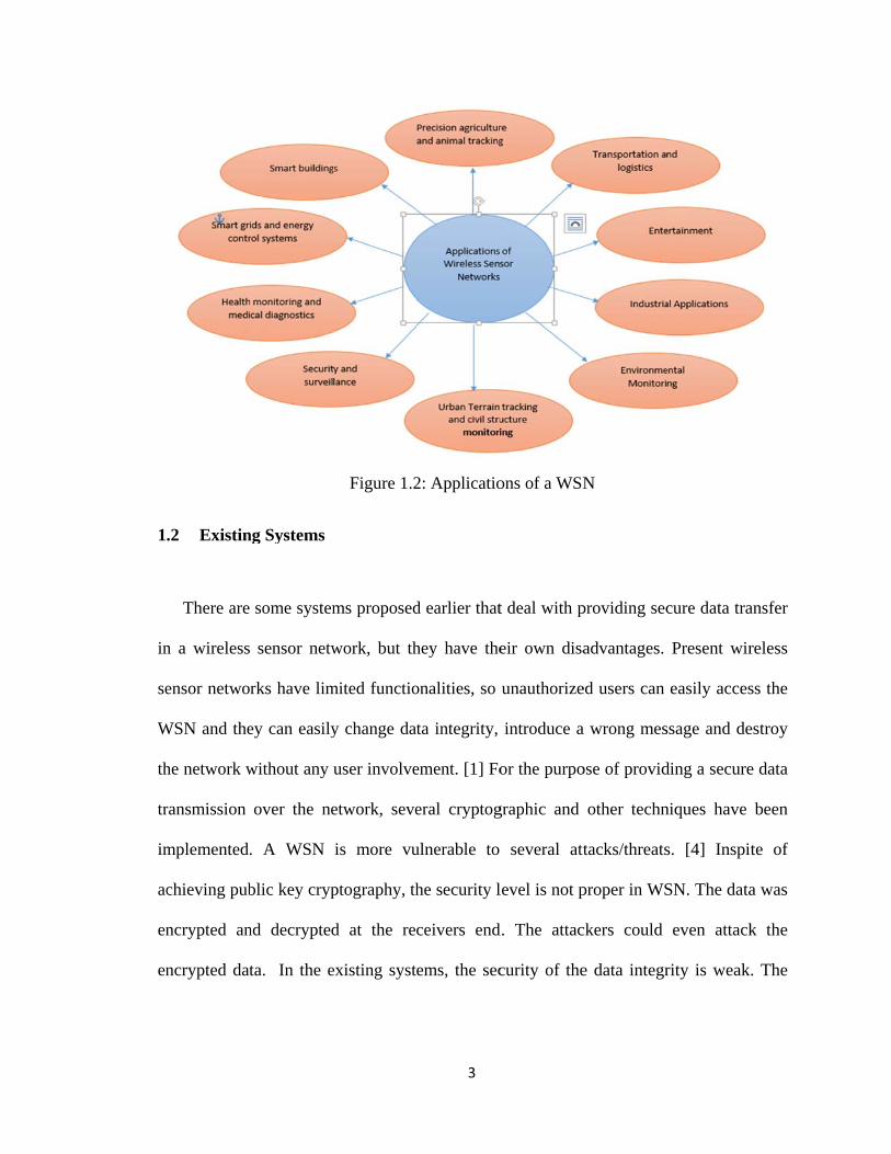
Figure 1.2: Applications of a WSN……………………………………………..3
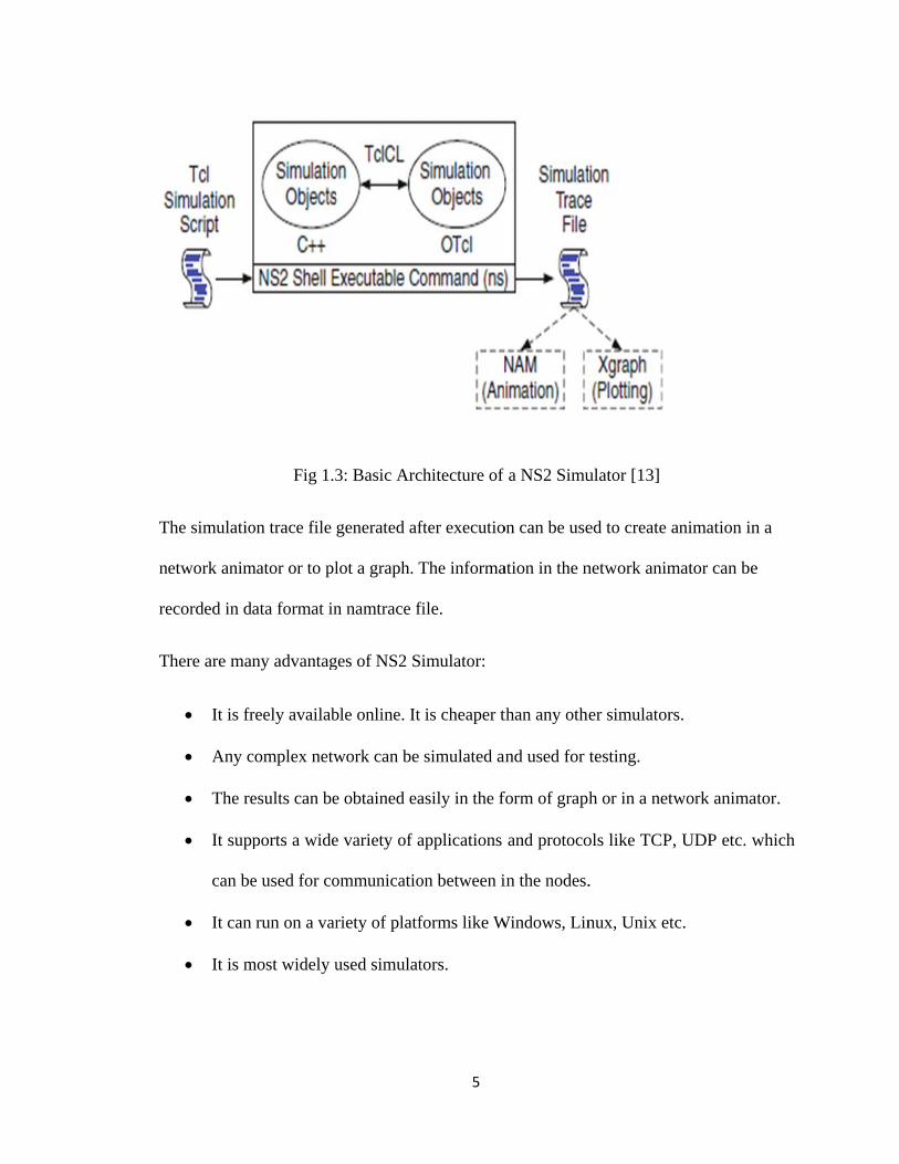
Figure 1.3: Basic architecture of a NS2 simulator……………………………...5
Figure 3.1: Components of a sensor node………………………………………9
Figure 3.2: Layered architecture…………………………………………….....10
Figure 4.1: Creation of nodes in the simulator…………………………………14
Figure 4.2: Partitioning into zones and assigning color codes…………………16
Figure 4.3: User entering the nodes…………………………………………….19
Figure 4.4: Simulation of Sybil attack………………………………………….21
Figure 4.5: Simulation of DOS attack…………………………………………..23
Figure 4.6: User making the nodes dynamic……………………………………24
Figure 4.7: Simulation of sinkhole attack……………………………………….25
Figure 4.8: User making the nodes dynamic……………………………………27
Figure 4.9: Simulation of hello flood attack…………………………………….27
Figure 5.1: Incorrectly entered node…………………………………………….29
Figure 5.2: Overlapping of nodes……………………………………………….30
Figure 5.3: Simulation of Sybil attack…………………………………………..31
Figure 5.4: Graph for throughput………………………………………………..32
1
1 BACKGROUND AND RATIONALE
1.1 Introduction to WSN
A WSN consists of sensor devices that are used to monitor physical and
environmental conditions like temperature, humidity, pressure etc. [1]. Figure 1.1
represents the architecture of a WSN. The WSN is built of hundreds and thousands of
detection stations called nodes, where each node connects to sensors. Each WSN consists
of a radio transceiver, an internal/external antenna, a microcontroller and a battery.
Constructing a wireless sensor network (WSN) has become important in all places. [2]
Small sensor devices can perform multiple tasks like data processing, sensing and
communicating with other devices in the wired network. A Wireless sensor network is
used for easier system design and monitoring the device in wireless network. Many
sensors are deployed in various places, hence they need security for transferring data
through the network. Using some technologies and efficient techniques we can create a
secure data transfer scheme in WSN. Wireless sensor network security plan must have
effective key distribution among all different nodes in same network.
2
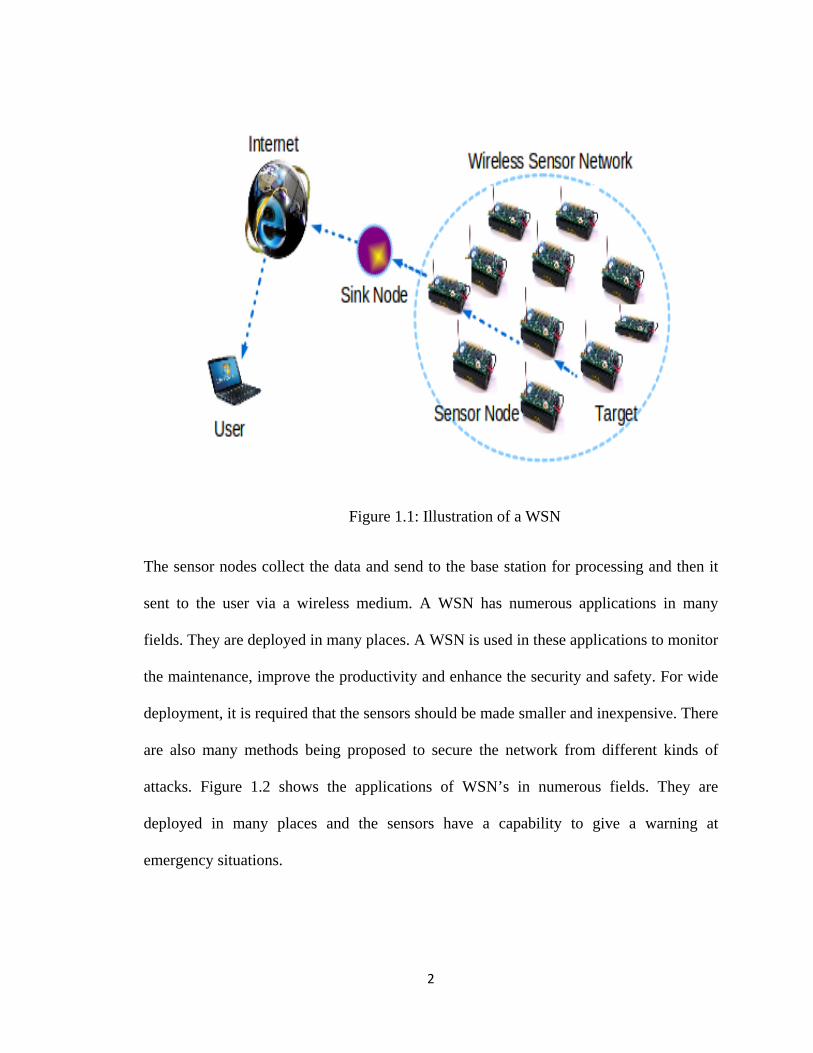
Figure 1.1: Illustration of a WSN
The sensor nodes collect the data and send to the base station for processing and then it
sent to the user via a wireless medium. A WSN has numerous applications in many
fields. They are deployed in many places. A WSN is used in these applications to monitor
the maintenance, improve the productivity and enhance the security and safety. For wide
deployment, it is required that the sensors should be made smaller and inexpensive. There
are also many methods being proposed to secure the network from different kinds of
attacks. Figure 1.2 shows the applications of WSN’s in numerous fields. They are
deployed in many places and the sensors have a capability to give a warning at
emergency situations.
1
in
se
W
th
tr
im
ac
en
en
.2 Existin
There are
n a wireless
ensor netwo
WSN and the
he network w
ransmission
mplemented.
chieving pub
ncrypted an
ncrypted dat
ng Systems
some system
sensor netw
rks have lim
ey can easily
without any
over the ne
. A WSN
blic key cryp
nd decrypted
ta. In the e
Figure 1.2
ms proposed
work, but th
mited functio
y change dat
user involve
etwork, seve
is more vu
ptography, th
d at the rec
existing syst
3
2: Applicatio
d earlier that
hey have the
onalities, so
ta integrity,
ement. [1] Fo
eral cryptog
ulnerable to
he security l
ceivers end
ems, the sec
ons of a WSN
t deal with p
eir own disa
unauthorize
introduce a
or the purpo
graphic and
several att
level is not p
d. The attac
curity of the
N
providing sec
advantages.
ed users can
a wrong mes
ose of provid
other techn
tacks/threats
proper in WS
ckers could
e data integr
cure data tra
Present wir
easily acces
ssage and de
ding a secure
niques have
s. [4] Inspi
SN. The data
even attack
rity is weak
ansfer
reless
ss the
estroy
e data
been
te of
a was
k the
. The

4
attacker can attack all the information in the intermediate nodes which violates data
confidentiality.
1.3 Introduction to NS2 Simulator
Using the network simulator NS2, the attacks in the WSN can be simulated. NS2
creates a replica of a real time network. It is a time based event driven simulator. The
code can be written in such a way that at what time, what particular event can happen.
The nodes can be created, the data transfer between the nodes and the attacks can be
shown. It has become one of the most widely used open source simulators. It is a free
simulation tool that can be available online [14] [19]. The simulator consists of a wide
variety of applications, protocols like TCP, UDP and many network parameters. It runs
on various platforms like UNIX, Mac and windows platforms. This NS2 tool allows to
develop a model design for wireless sensor network connection between nodes in the
network. Based on the network attacks like denial of service [4], hello flood attack,
sinkhole attacks, Sybil attack the network security can be tested. These attacks can be
created in the network and the security level of the wireless sensor network can be tested
to ensure secure data transmission between the nodes in the network.
Figure 1.3 shows the basic architecture of NS2 Simulator [13]. It is provided with a
command ‘ns’ to execute the code written in NS2. The name of the Tcl simulation script
is passed as an input argument. After executing a simulation trace file is created which
can be used to create animation or to plot graph. NS2 Simulator consists of two languages
namely C++ and OTcl (Object oriented Tool Command Language). C++ does the internal
mechanism i.e. back end and OTcl deals with the front end [12].
T
n
re
T
The simulatio
etwork anim
ecorded in d
There are man
It is fr
Any c
The re
It supp
can be
It can
It is m
Fig 1.3
on trace file
mator or to pl
ata format in
ny advantag
reely availab
complex netw
esults can be
ports a wide
e used for co
run on a var
most widely u
3: Basic Arc
generated af
lot a graph. T
n namtrace f
ges of NS2 S
ble online. It
work can be
e obtained ea
e variety of a
ommunicatio
riety of platf
used simulat
5
chitecture of
fter executio
The informa
file.
imulator:
is cheaper t
simulated a
asily in the f
applications
on between i
forms like W
tors.
f a NS2 Simu
on can be use
ation in the n
than any othe
and used for
form of graph
and protoco
in the nodes.
Windows, Lin
ulator [13]
ed to create a
network anim
er simulator
testing.
h or in a net
ols like TCP
.
nux, Unix et
animation in
mator can be
rs.
twork animat
, UDP etc. w
tc.
n a
e
tor.
which

6
1.4 Introduction to Proposed System
A WSN has numerous applications in many fields. It is deployed in many
places. Ensuring the security in a WSN is of great concern. Because of the constraints in
the network, it is vulnerable to many attacks. The major attacks include denial of service,
sinkhole, Sybil and hello flood attack. [4] These attacks decrease the performance and
efficiency of the network. The attacks are studied in detail and are simulated in a
simulator. The characteristics of the attack and the nature of the attack can be known. By
simulating, the behavior of the network and the performance can be examined. The
network simulated is closer to real time network. By understanding the attacks, proper
measures can be taken in order to detect and prevent them. A simulator holds good for
replicating the real time network. By understanding all the problems in the design phase
itself, one can be able to construct a more efficient network.
7
2 NARRATIVE
2.1 Motivation
Wireless Sensor networks are employed in various applications such as health,
military and many other organizations. They provide tremendous benefits to industries.
The ability to add sensors without wires has led to many benefits including energy,
material and labour savings, productivity also increases [11]. WSN’s are deployed in
many places and have numerous applications. Several computation problems such as
small memory, limited energy resources cause difficulty in security and protection in
WSN’s. It is very necessary to protect WSN’s from several attacks/threats. To ensure
confidentiality of data, a WSN should be secure.
2.2 Project Objective
As said earlier, the WSN’s are deployed in many places, they need to be
prevented from attacks. Because of the many constraints in a WSN, it is vulnerable to
many attacks. Understanding the attacks and providing security in the network is of great
necessity. By using the network simulator NS2, the attacks can be simulated. By the
simulation of the attacks, the attacks can be understood clearly and proper measures to
detect and prevent the attacks can be taken. It is also cost effective and closer to a real
time scenario.
8
2.3 Project Scope
Though the WSN has many limitations with the energy consumption,
resource utilization, limited battery power etc., they are being used in many organizations
and places. WSN’s are vulnerable to many threats and attacks which are very common.
Hence there is much necessity for security in a WSN. WSN’s have the capability to
protect attackers in broadcast transmission medium. Based on the some advance
techniques wireless sensor network have an extra safe susceptibility. With simulating the
attacks, the performance and the efficiency of the network can be known before even
constructing the network. The behavior and the communication between the nodes can be
understood in a better way. They can prevent the network layers from the DOS,
wormhole attack, hello flood attack, sinkhole attack, Sybil attack [2] and selective
forwarding attack [7].

9
3 PROPOSED SYSYEM DESIGN
3.1 System Design and Architecture
Figure 3.1 explains about the basic design of the sensor network and how all the
nodes are connected in the network. The power generator supplies power to the power
unit. The power unit supplies power to the sensing unit, processing unit and the
transmission unit. Each sensor node is connected to a base station for communication by
which it can send and receive data. It consists of a position finding system, mobilizer,
sensing unit, processing unit and a transmission unit. BS indicates the base station.

10
Figure 3.1: The components of a sensor node [1]
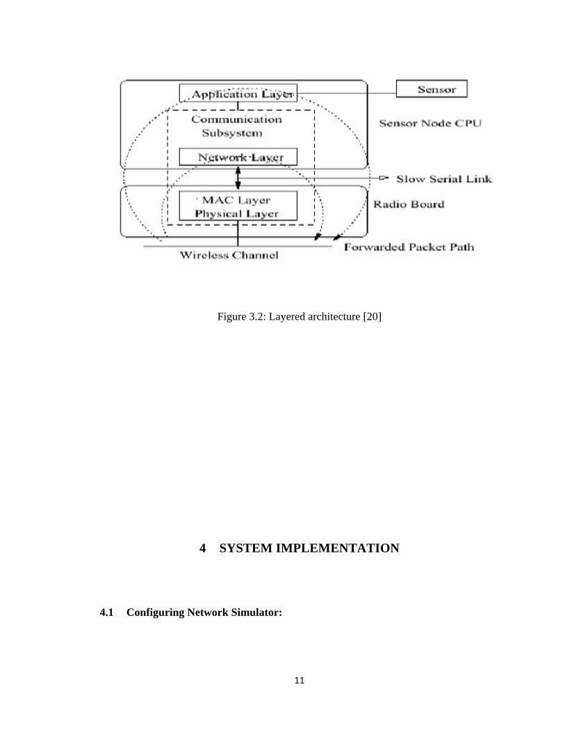
Figure 3.2 describes the details of the different layers in the wireless network and
the communication process between the nodes and the wireless device. A WSN consists
of an application layer, network layer, MAC and physical layer. The Sensor operates in
the application layer. The packet is forwarded through a wireless channel from physical
layer to application layer.
11
Figure 3.2: Layered architecture [20]
4 SYSTEM IMPLEMENTATION
4.1 Configuring Network Simulator:
12
As said earlier WSN’s are vulnerable to many attacks. Each attack may lead to a
different problem. There are two types of attacks that are popular with the Wireless
Sensor Networks. They are Physical attacks and logical attacks. [13] Physical attacks
include capturing of the nodes and tampering the nodes which will lead to loss of data.
On the other hand, Logical attacks include attacks like sinkhole attack, wormhole attack,
hello flood attack, selective forwarding attack, Sybil attack, Denial of service attack.
These attacks are more common in a Wireless Sensor Network. These attacks must be
detected and must be avoided in order to increase the performance and security level in a
WSN.
The Simulation of the attacks is being done by using NS2 Simulator. It is an open
source free simulator available online. It stands good for simulation of TCP, UDP and
many other routing protocols. It works on an object oriented language called Tool
Command language (OTcl). With the help of OTcl language, different network
topologies and the routing protocols can be explained. [14] The language is very easy to
use and is platform independent. The code can be written for creation of the nodes,
showing the data transfer and introducing the attacks and the simulation can be shown by
running the simulator. The simulator consists of wide variety of applications, protocols
like TCP, UDP and many other network parameters. The simulator consists of nodes and
the data transfer between the nodes can be shown. The attacks can be introduced into the
system by making some of the nodes malicious. In our system the simulation is shown
on four attacks mainly Sybil attack, sinkhole attack, hello flood attack and denial of
service attack.
4.1.1 Creating and setting connection between the nodes in the simulator:
13
The first step is creation of the nodes in the network. Any number of nodes can be
created in the network as per the user. The nodes can be made dynamic. The user can
enter the source, destination and malicious node as he wishes when he runs the simulator.
Figure 4.1 shows the creation of the nodes in the network. The movement of the nodes
can be generated and the nodes can be partitioned into zones. After creating the nodes, a
connection must be established between the nodes in the network. There are several
protocols defined that can be used namely TCP and UDP. TCP is connection oriented
protocol and it provides acknowledgement from the receiver. The UDP protocol can be
used when there is a lot of traffic in the system which would be efficient. There is a TCP
agent and a TCP sink. TCP agent is responsible for sending the packets in the network
which can be called as a source node. TCP sink is the receiver node which receives the
packets sent by the receiver.
Following shows how to create a node in the simulator. nn represents the number of
nodes being initialized. The looping is done through the number and nodes and each node
is created and assigned a random motion.
Code:

F
co
m
C
ollowing sh
ontains all th
mode and the
Code:
ows how to
he tcp conne
e tcp connect
set up TCP
ections in th
tion is set an
14
connection
e network in
nd the file is
between the
n data forma
attached.
e nodes. gpsr
at. The file i
rtace is a file
s opened in
e that
write

4
in
se
F
w
.1.2 Settin
Th
nitialized. It
et at a partic
ollowing sho
whereas as th
Fig
ng the positi
he X dimens
represents th
ular coordin
ows how to
he Y and Z ar
gure 4.1: Cre
ion of the no
sion and the
he area in th
nate in the sim
set the posit
re set to 0.
15
eation of nod
odes
Y dimension
he simulator.
mulator.
tion of the no
des in the sim
n of the topo
The initial
odes. The X
mulator
ography in th
location of t
coordinate i
he system w
the nodes ca
is set to 20,
ill be
an be

C
4
m
b
F
m
C
$n
4
as
ot
Code:
.1.3 Gener
S
movements o
e moved to a
ollowing sho
moves to the
Code:
ns at 0.2 "$n
.1.4 Zone
The
ssigned to e
ther.
ration of mo
Since it is a W
of the nodes i
a particular d
ows the gene
particular de
node_(49) se
Partitionin
e nodes crea
ach node. T
ovements
WSN, the no
in the simula
destination c
eration of m
estination.
etdest 100.7
g
ated can be p
This is just fo
16
odes keep m
ator can be d
can be set.
movement of
8 980.56 3
partitioned in
or a clear vi
moving in the
done. The tim
a node. The
3000"
nto different
iew and iden
e simulator. T
me at which
e node 49 at t
nt zones. A c
ntifying the
The generati
the node sh
time 0.2 sec
color code ca
nodes from
ion of
hould
an be
each

F
th
sh
C
$n
$n
$n
ollowing sh
hem. The ou
hown in figu
Code:
ns at 9.3 "$n
ns at 9.3 "$n
ns at 9.3 "$n
hows the par
utline of the
ure 4.2.
node_(38) a
node_(74) a
node_(81) a
Figure 4.2:
rtitioning of
e nodes 38,
add-mark c3
add-mark c3
add-mark c3
Partitioning
17
the nodes i
74, 81 will
pink circle"
pink circle"
pink circle"
g into zones
into zones an
be made pi
and assignin
nd assigning
ink at time
ng color cod
g a color co
9.3 sec whi
des.
ode to
ich is

4
re
tr
th
ap
n
C
C
.1.5 Creat
The
eceiver. Her
raffic. The o
he applicatio
pplication st
ode. Follow
CBR applicat
Code:
ting Applica
application
e, constant b
other applica
on like time
tarts at a par
wing shows h
tion are initia
ation:
n indicates th
bit rate (CBR
ations that c
e interval, m
rticular time
how to set a
alized and th
18
he type of tr
R) is used a
an be used
maximum pa
, the packets
a CBR appl
he applicatio
ransmission
as an applica
are FTP, Te
ackets size
s will be sen
lication to U
on is started.
n between th
ation in orde
elnet etc. Th
etc are set.
nt from one
UDP. The pa
he sender an
er to generat
he parameter
When the
node to the
arameters fo
nd the
te the
rs for
CBR
other
or the
4
k
to
C
$n
4
ow
th
F
te
C
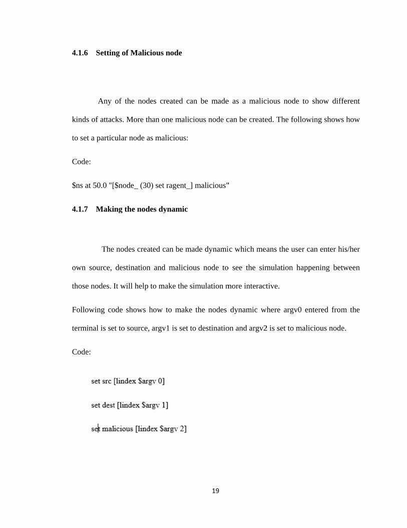
.1.6 Settin
Any
inds of attac
o set a partic
Code:
ns at 50.0 "[
.1.7 Maki
The
wn source,
hose nodes. I
ollowing co
erminal is se
Code:
ng of Malici
of the node
cks. More tha
cular node as
[$node_ (30)
ng the node
nodes creat
destination
It will help t
ode shows h
t to source, a
ous node
es created ca
an one malic
s malicious:
) set ragent_
es dynamic
ted can be m
and malicio
to make the s
how to make
argv1 is set t
19
an be made
cious node c
] malicious"
made dynami
ous node to
simulation m
e the nodes
to destinatio
e as a malic
can be create
"
ic which mea
o see the sim
more interact
dynamic w
on and argv2
cious node t
ed. The follo
ans the user
mulation hap
tive.
where argv0
2 is set to ma
to show diff
owing shows
can enter hi
ppening bet
entered from
alicious node
ferent
s how
is/her
tween
m the
e.
T
h
m
m
4
at
th
as
fa
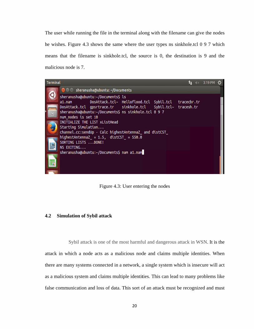
The user whil
e wishes. Fi
means that th
malicious nod
.2 Simula
S
ttack in whi
here are man
s a maliciou
alse commun
le running th
igure 4.3 sh
he filename
de is 7.
ation of Sybi
ybil attack i
ich a node a
ny systems c
s system and
nication and
he file in the
ows the sam
e is sinkhole
Figure 4.3
il attack
s one of the
acts as a m
onnected in
d claims mu
d loss of data
20
e terminal alo
me where the
e.tcl, the so
3: User enter
most harmfu
alicious nod
a network, a
ultiple identit
a. This sort o
ong with the
e user types
ource is 0, t
ring the node
ful and dange
de and claim
a single syst
ties. This can
of an attack m
e filename ca
s ns sinkhole
the destinati
es
erous attack
ms multiple
tem which is
n lead to ma
must be reco
an give the n
e.tcl 0 9 7 w
ion is 9 and
in WSN. It
identities. W
s insecure wi
any problem
ognized and
nodes
which
d the
is the
When
ill act
ms like
must

21
be prevented so that the system can be made secure. Maintaining the identities of the
system is necessary. There are many authorities that help in maintaining the identity by
using certification software’s [15]. Sybil attacks are the most common types of attacks.
They tend to challenge the security and safety of the system. There are many ways to
protect a system from Sybil attack. Trusted authority and proper identity can help prevent
a network from such type of an attack.
The simulation of the Sybil attack is done by using the NS2 Simulator. It can be done by
modifying aodv.cc file in ns2.35 which can be shown by dropping the packets in the
simulator. Figure 4.4 shows the simulation of the Sybil attack. The attack can be seen by
dropping of the packets of the intermediate node. This attack is one of the well-known
attack in WSN. The attacker nodes may obtain the legitimates IP Address or Mac
Address in order to Steal and make its own. Then the attacker node can do plenty of
things with new stolen identity. Node 43 acts as source whereas node 44 is the destination
node. The source node start sending packets to the destination node through the shortest
path that is decided by the routing protocol. The intermediate node 15 acts as a malicious
node and at time 30 sec, it starts dropping the packets coming from the node.

4
re
fo
le
re
N
ev
.3 Simula
W
esources ma
ocusses on t
egitimate. It
equests. Due
Network wou
ven more ha
ation of Den
WSN are co
akes the W
the energy p
can be don
e to this at
uld be reduc
armful. Ther
Figure 4.4:
nial of Servi
oncerned wi
WSN more v
protocols. [1
ne by overlo
ttack, efficie
ed. This par
re are many
22
Simulation
ice attack
ith numerou
vulnerable t
6] DoS attac
oading the d
ency and th
rticular type
types of DO
of Sybil atta
us security i
to Denial o
ck prevents
destination s
he performa
of attack in
OS attacks. A
ack
ssues. The c
of Service a
the system
system with
ance of the
n unfriendly
Among the d
constraint o
attack becau
or the user
huge numb
Wireless S
situations ca
different typ
n the
use it
to be
ber of
ensor
an be
pes of
23
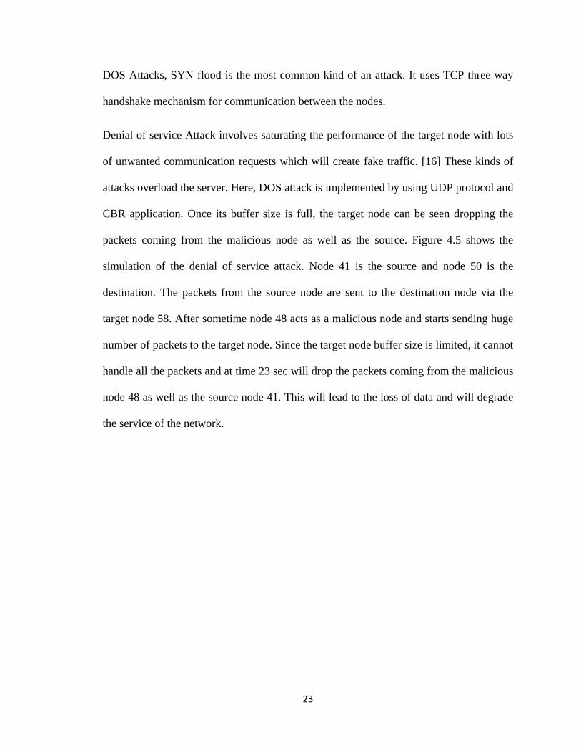
DOS Attacks, SYN flood is the most common kind of an attack. It uses TCP three way
handshake mechanism for communication between the nodes.
Denial of service Attack involves saturating the performance of the target node with lots
of unwanted communication requests which will create fake traffic. [16] These kinds of
attacks overload the server. Here, DOS attack is implemented by using UDP protocol and
CBR application. Once its buffer size is full, the target node can be seen dropping the
packets coming from the malicious node as well as the source. Figure 4.5 shows the
simulation of the denial of service attack. Node 41 is the source and node 50 is the
destination. The packets from the source node are sent to the destination node via the
target node 58. After sometime node 48 acts as a malicious node and starts sending huge
number of packets to the target node. Since the target node buffer size is limited, it cannot
handle all the packets and at time 23 sec will drop the packets coming from the malicious
node 48 as well as the source node 41. This will lead to the loss of data and will degrade
the service of the network.

4
se
in
n
H
n
cl
.3.1 Simu
A
end the colle
n cases wher
etworks and
Here, a malic
odes. Sinkh
loser to the
ulation of Si
A WSN cons
ected data to
re there is m
d proper me
cious node a
hole attack i
destination
Figure 4.5:
inkhole atta
sists of many
o the base st
many to one
easures shou
acts as desti
s the select
n node in or
24
Simulation
ack:
y nodes conn
tation for pro
e communica
uld be taken
ination node
ive forward
rder to attra
of DOS atta
nnected to ea
ocessing. A
ation. It is a
n in order to
e and looks
ding attack.
act all maxi
ack
ach other. Th
sinkhole att
a serious thr
o detect and
attractive to
The malicio
imum possib
hese nodes w
tack is more
reat to the s
d prevent it
o the surroun
ous node wi
ble traffic o
would
e seen
ensor
[18].
nding
ill be
of the
n
d
at
ro
th
si
n
u
w
d
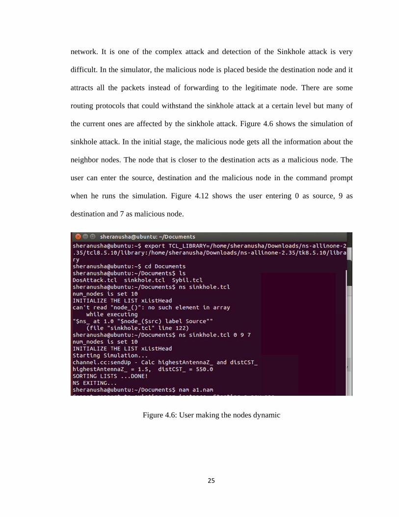
etwork. It i
ifficult. In th
ttracts all th
outing proto
he current on
inkhole attac
eighbor nod
ser can ente
when he run
estination an
s one of the
he simulator
he packets i
cols that cou
nes are affec
ck. In the in
des. The nod
er the source
ns the simul
nd 7 as malic
Fi
e complex a
r, the malicio
instead of f
uld withstan
cted by the
itial stage, th
de that is clo
e, destinatio
lation. Figur
cious node.
gure 4.6: Us
25
attack and d
ous node is p
forwarding t
nd the sinkh
sinkhole att
he malicious
oser to the d
on and the m
re 4.12 show
ser making th
detection of
placed besid
to the legiti
hole attack at
tack. Figure
s node gets
destination a
malicious no
ws the user
he nodes dyn
f the Sinkho
de the destin
imate node.
t a certain le
4.6 shows t
all the infor
acts as a mal
ode in the c
r entering 0
namic
ole attack is
nation node a
There are
evel but man
the simulatio
rmation abou
licious node
command pr
0 as source,
very
and it
some
ny of
on of
ut the
. The
rompt
9 as

A
n
an
fr
b
4
ty
As entered by
ode and nod
nd attracts a
rom the sour
e seen in the
.3.2 Simu
He
ype of attack
y the user, no
de 7 is made
ll the maxim
rce are sent t
e figure 4.7.
F
ulation of H
ello Flood at
k a malicious
ode 0 becom
a malicious
mum possible
to the malici
Figure 4.7: S
ello Flood A
ttack is also
s node keeps
26
mes the sourc
node. The m
e traffic in th
ous node ins
Simulation o
Attack:
one of the m
s sending he
ce node, nod
malicious no
he network.
stead of the
f sinkhole at
most commo
ello requests
de 9 becomes
ode acts as a
All the pack
destination n
ttack
on attacks in
to the legiti
s the destina
legitimate n
kets being se
node which
n a WSN. In
imate node w
ation
node
ent
can
n this
which

27
will alter the security of the system. [17] The node which receives such a message
assumes that it has been sent by the sender which is not the case always. It can occur
when there is huge amount of traffic in the system. Several cryptographic techniques and
methods have been implemented in order to prevent this attack but each one had its own
drawback.
This attack can be simulated by modifying the Aodv.h and Aodv.cc file in ns2 simulator
in order to create hello flood attack where we can see the target node being flooded by
the packets. These files are the inbuilt files that come along with the ns2 package when
one downloads. They contain all the code about the routing, providing a path for routing
and information on the packet forwarding. Figure 4.8 shows the simulation of hello flood
attack. A node is made as a target node and it is flooded with lots of hello messages
which will create a lot of black circles in the simulator. The user can enter the source and
destination as he wishes which is shown in figure 4.9.Here, the node 0 is made as the
source and the node 9 is made destination. Every node is seen sending hello messages to
every other nodes in the network.

Fi
Fi
gure 4.8: Us
igure 4.9: Sim
28
ser making th
mulation of
he nodes dyn
hello flood a
namic
attack
29
5 TESTING AND EVALUATION
Using the network simulator NS2, the attacks can be simulated. It creates a
replica of a real time network [12]. NS Simulators are mainly used for network research
and learning. It helps me to create security nodes and establish the communication
between them. This NS2 tool allows to develop a model design for WSN connection
between nodes in the network. Based on the network attacks like Dos, wormhole attack,
hello flood attack, sinkhole attacks, Sybil attack, selective forwarding attacks, the
network security can be tested [9]. NS2 tool gives scope in testing, so the level of
network security can easily be tested. The attacks can be created in the network and the
security level of the wireless sensor network can be tested. Here, for the given input, what
output it is generating are my test cases.
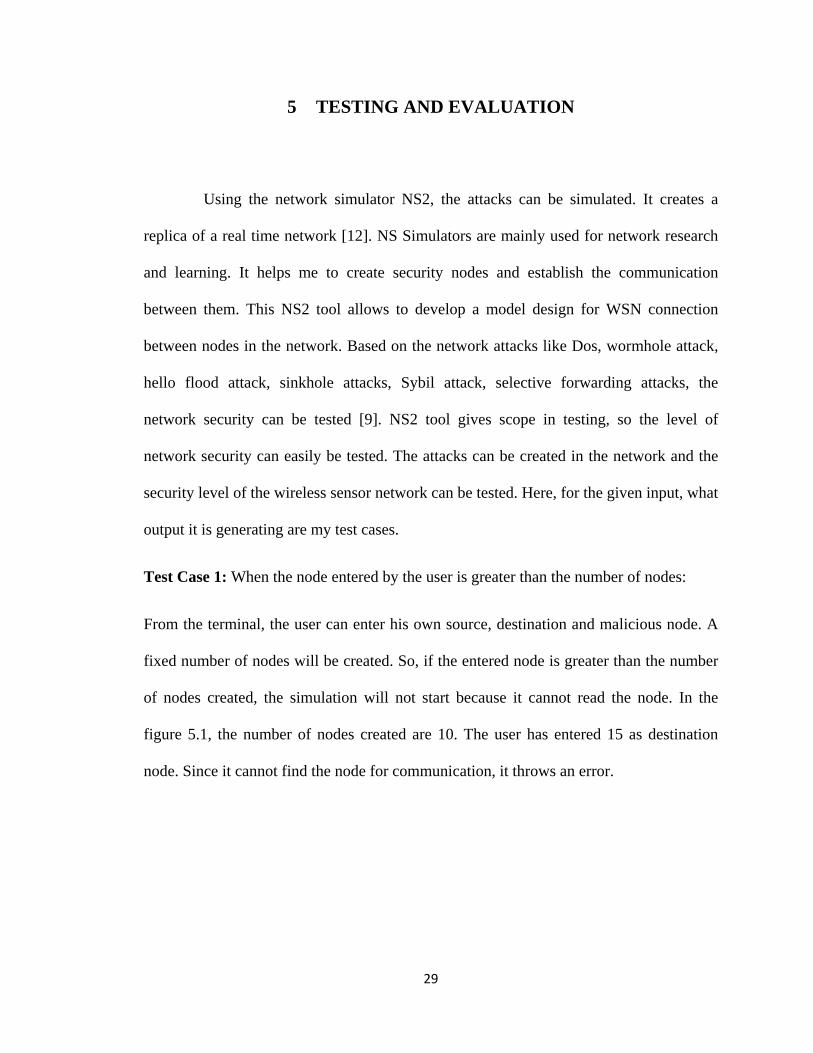
Test Case 1: When the node entered by the user is greater than the number of nodes:
From the terminal, the user can enter his own source, destination and malicious node. A
fixed number of nodes will be created. So, if the entered node is greater than the number
of nodes created, the simulation will not start because it cannot read the node. In the
figure 5.1, the number of nodes created are 10. The user has entered 15 as destination
node. Since it cannot find the node for communication, it throws an error.

T
It
d
d
tr
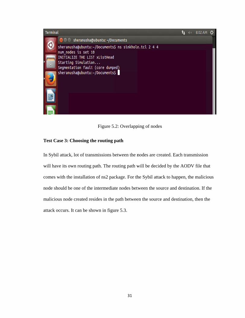
Test Case 2:
t can be te
estination n
estination a
ransmission
Overlapping
sted with s
node will a
s well as m
and will crea
Figure 5.1
g of nodes
sinkhole atta
ct as malic
malicious no
ate a segmen
30
: Incorrectly
ack. In sink
cious node.
de, the atta
ntation fault
y entered nod
khole attack
If the user
ack will not
. Figure 5.2
de
k, a node t
r gives the
happen. It
shows the sa
that is clos
e same nod
will overlap
ame.
ser to
e for
p the
T
In
w
co
n
m
at
Test Case 3:
n Sybil attac
will have its o
omes with th
ode should b
malicious nod
ttack occurs
Choosing t
k, lot of tran
own routing
he installatio
be one of the
de created re
. It can be sh
Figure 5.
he routing p
nsmissions b
path. The ro
on of ns2 pac
e intermediat
esides in the
hown in figu
31
.2: Overlapp
path
between the n
outing path w
ckage. For th
te nodes bet
path betwee
ure 5.3.
ping of nodes
nodes are cre
will be decid
he Sybil atta
tween the sou
en the source
s
eated. Each
ded by the A
ack to happen
urce and des
e and destina
transmission
AODV file th
n, the malici
stination. If t
ation, then th
n
hat
ious
the
he

5
n
ov
af
p
U
A
.1 Results
As a p
etwork perfo
verall numb
ffected by v
erformance.
Using the gra
Axis represen
art of the p
formance. It
ber of bytes r
various num
The trace f
aph, one can
nts the time
Figure 5.3:
proposed sy
calculates th
received in
mber of facto
file generated
n easily unde
and Y Axi
32
Simulation
ystem, a gra
he throughp
the network
ors. It plays
d is passed
erstand the s
s represents
of Sybil atta
aph has bee
put of the ne
k. The Throu
s a vital rol
as an input
simulation re
s the through
ack
en generated
etwork. Thro
ughput in the
le in analyz
in order to g
esults of the
hput rate. In
d to monito
oughput indi
e network ca
zing the net
generate a g
e network. T
nitially, whe
or the
icates
an be
twork
graph.
The X
en the
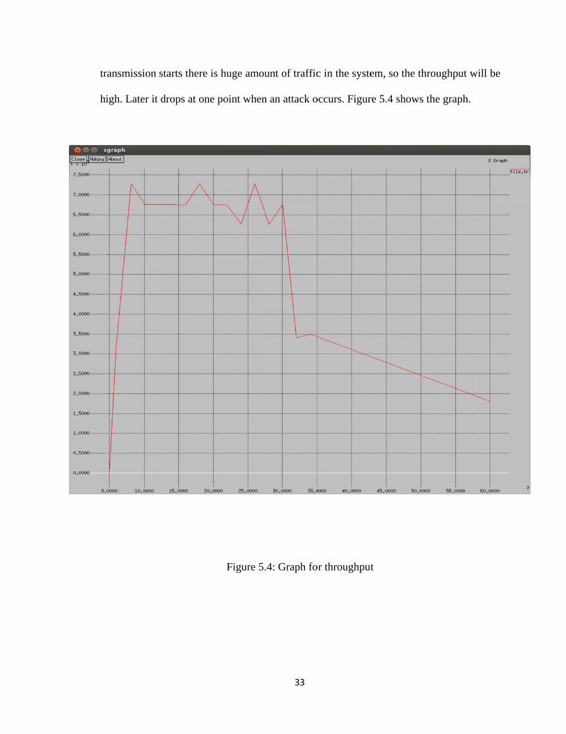
tr
h
ransmission
igh. Later it
starts there i
drops at one
is huge amou
e point when
Figure 5.
33
unt of traffic
n an attack o
.4: Graph fo
c in the syste
occurs. Figur
or throughput
em, so the th
re 5.4 shows
t
hroughput w
the graph.
will be
34
6 CONCLUSION AND FUTURE WORK
WSN’s are of huge demand. The request for wireless sensor networks are
increasing rapidly, because the growth of using WSN has increased. There are some
limitations in a wireless sensor network like they have limited storage capacity, limited
capability of processing and limited energy to transmit data [1]. These drawbacks can
make WSN different from other networks. There are some little concerns that occur in a
WSN. Based on the above mentioned difficulties in the data integrity, security, there are
many solutions that are available to overcome these dangers. The attacks that are popular
in a WSN like hello flood attack, sinkhole attack, Sybil attack and denial of service attack
have been simulated in a simulator. On simulation, the performance and the efficiency of
the network can be analyzed. The behavior and the energy parameters can be examined.
A mechanism for ensuring secure data transfer and preventing the attacks in a WSN must
be proposed. The parameters which determine the network performance can be calculated
from the simulation. Because of the numerous attacks happening in the WSN, there is
less amount of security.

35
BIBLIOGRAPHY AND REFERENCES
[1] Y. Wang, G. Attebury, et al. "A survey of security issues in wireless sensor
networks." Computer Science and Engineering. Vol.8, no. 2. 2006.
[2] E. Shi and A. Perrig, “Designing Secure Sensor Networks,” Wireless Commun. Mag.,
vol. 11, no. 6, pp. 38–43, Dec. 2004.
[3] N. Gura, A. Patel, et al. "Comparing elliptic curve cryptography and RSA on 8-bit
CPUs." Cryptographic Hardware and Embedded Systems-CHES 2004, pp 925-943, 2004.
[4] M. Razzaque., S.Ahmad Salehi. Security and Privacy in Vehicular Ad- Hoc
Networks: Survey and the Road Ahead. Wireless Networks and Security, Springer: 107-
132, 2013.
[5] A. Perrig et al., “SPINS: Security Protocols for Sensor Networks,” Wireless
Networks, vol. 8, no. 5, pp. 521–34, Sept. 2002.
[6] H. Du, X. Hu, et al. "Energy efficient routing and scheduling for realtime data
aggregation in WSNs." Computer communications. Vol.29, no. 17. 3527-3535, 2006.
[7] X. Hung, et al. “An Energy-Efficient Secure Routing and Key Management Scheme
for Mobile Sinks in Wireless Sensor Networks Using Deployment Knowledge,” Sensors,
Vol 8. 2008, 7753-7782
[8] L. Jialiang, Valois, F.; Dohler, M.; Min-You Wu; "Optimized Data Aggregation in
WSNs Using Adaptive ARMA," Sensor Technologies and Applications
(SENSORCOMM), 2010 Fourth International Conference on pp.115-120, 18-25 July
2010.

36
[9] S. Zhu et al., “An Interleaved Hop-by-Hop Authentication Scheme for Filtering of
Injected False Data in Sensor Networks,” Proc. IEEE Symp. Security and Privacy,
Oakland, CA, pp. 259–71, May 2004.
[10] J. Ben-Othman, and B. Yahya. "Energy efficient and QoS based routing protocol for
wireless sensor networks." Journal of Parallel and Distributed Computing 70(8), 849-857
2010.
[11] D.W. Carman, P.S. Krus, and B.J. Matt, “Constraints and approaches for distributed
sensor network security”, Technical Report 00-010, NAI Labs, Network Associates Inc.,
Glenwood, MD, 2000.
[12] Teerawat Issariyakul and Ekram Hossain.
Introduction%20to%20Network%20Simulator%20NS2%20(1).pdf
[13] R. E. Shannon, “Introduction to the art and science of simulation,” in Proc. of the
30th conference on winter simulation (WSC’98), 1989
[14] http://ns2tutor.weebly.com/ns2-in-windows.html
[15] http://www.cs.berkeley.edu/~dawnsong/papers/sybil.pdf
[16] http://ieeexplore.ieee.org/stamp/stamp.jsp?tp=&arnumber=4431860
[17]http://citeseerx.ist.psu.edu/viewdoc/download?doi=10.1.1.403.6592&rep=rep1&type
[18] http://ijaiem.org/Volume2Issue2/IJAIEM-2013-02-06-005.pdf
[19] http://sourceforge.net/projects/nsnam/files/
[20] http://www.ipcsit.com/vol35/003-CNCS2012-N010.pdf
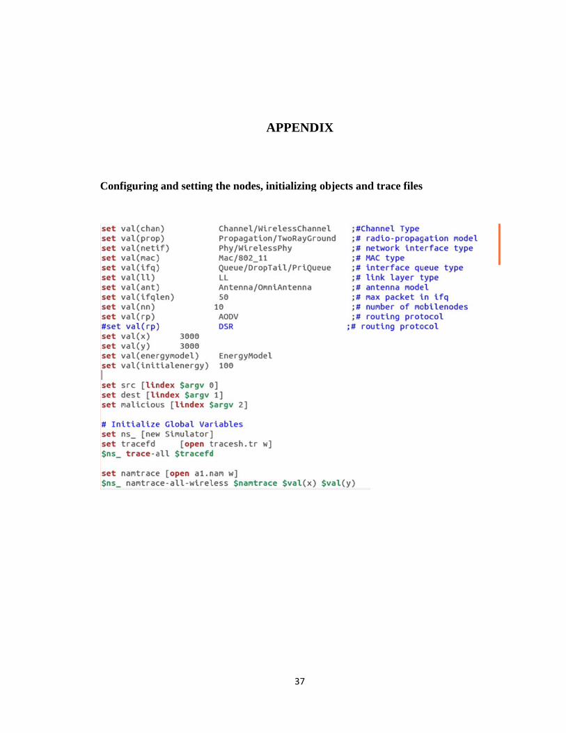
C
Configuring and settingg the nodes,
37
APPEND
initializing
DIX
objects andd trace files

S
etting topoggraphy and setting the
38
values to thhe configureed parameteers

C
L
Creation of n
Labelling the
nodes and s
e nodes and
etting positi
d setting TC
39
ion of the n
CP connectio
nodes
on between the nodes

S
etting of CBBR applicattion
40

C
T
th
dr
C
Code for ma
These are som
he ns2. Thes
rop the pack
Code for sink
alicious node
me of the lin
e lines are fo
kets. It is com
khole attack
e:
es that I hav
or setting up
mmon for all
k:
41
ve added in th
p the malicio
l the four att
he AODV.c
ous node and
tacks.
c which is a
d making the
an inbuilt file
e malicious n
e in
node

CCode for Doss attack:
42
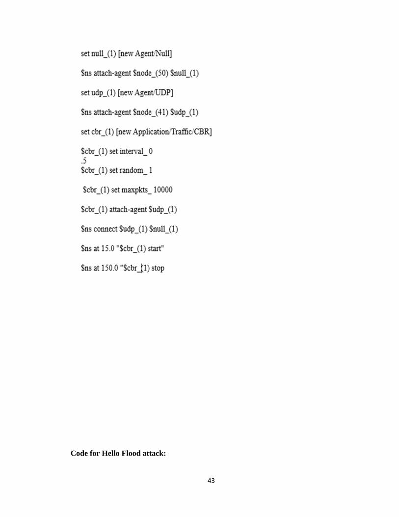
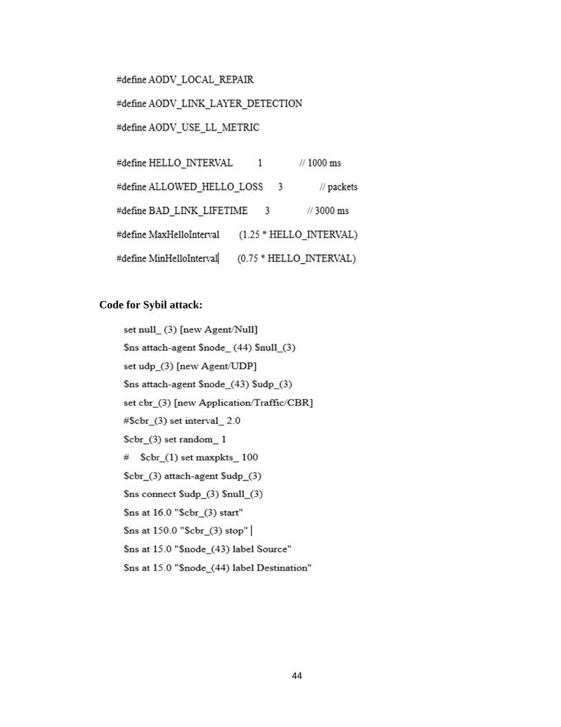
CCode for Helllo Flood attack:
43
C
Code for Sybbil attack:
44