graduate aeronautical laboratories … · in subsonic shear layers (pa.pamoschou 1989, fourguette...
TRANSCRIPT
GRADUATE AERONAUTICAL LABORATORIES CALIFORNIA INSTITUTE of TECHNOLOGY
Pasadena, California 91 125
0 1 1 the coiivection velocity of turbulent structures in supersonic shear layers
by,
Paul E. Dimotakis
G ALCIT Report FM90-4
24 September 1990

An ansatz, complemented by appropriate selection rules, is proposed to estimate the
convection velocity U, of turbulent vortical structures in supersonic shear layers. The
proposed scheme assumes that, for supersonic convective Mach numbers, shocks will form in
one of the two shear layer free streams. The strength of the shocks is estimated by assuming
that the flow configuration is stationary with respect to perturbations in the mean flow
quantities caused by the turbulent fluctuations. Given the shock strength, the convection
velocity U, and the associated convective Mac11 numbers are calculated by matching the
estimated total pressure at the stagnation points in the convected frame. The data indicate
a convection velocity U, that is close to that of one of the free streams. That appears to be
well accounted for by the proposed scheme, which also suggests that the flow can undergo
large jumps in configuration with small changes in the flow parameters. This has important
implications for supersonic mixing and hypersonic propulsion applications.

Introduction
Recent experiments in compressible flow shear layers indicate that the convection ve-
locity U, of turbulent structures in supersonic shear layers is much closer to the high or
low speed free stream velocities, U1 or U2, respectively, than 11% been found to be the case
in subsonic shear layers (Pa.pamoschou 1989, Fourguette & Dibble 1990, Hall et al. 1990).
Such asymmetric behavior suggests, in turn, that the entraininent rate of free stream fluid
into the turbulent illixiag region can potentially be expected to be greatly asymmetric.
An important a.ttribute of the turbulent structure convection velocity is the proposed
role i t plays in the shear layer ei~tra~inment process. Specifically, it was proposed that
E,, the volumetric entrainment ratio in spa.tially growing mixing layers, i.e. the entrained
volume (flux) of high speed fluid fluid per unit volume flux of low speed fluid*, can be
estimated as
where !/x is the loca.1 large scak structure streailzwise extent to position ratio (Dimotakis
1984). The large structtlre streainwise extent ! is, in turn, expected to be of the order of
the local transverse extent (visual thickness) of the layer 6, i.e.
with subsonic experiments yielding a value for the constant of proportionality of
It was recently suggested (Clemens & Mungal 1990) that the fact that compressible shear
layers do not appear to be c1ia.racterized by two-dimensional, spa.nwise coherent structures
may render the validity of the use of the espressioll in Eq. 1, for example, questionable.
To address this issue, a brief review of the arguments that lead to this expression may be
useful.
The first factor in Eq. 1 derives from the induction velocity ratio and scales the relative
shear sustained between the turbulent structures and the corresponding free stream. No
relative velocity, no shea.r, no entrainment**. Under supersonic flow conditions and the
possible presence of shoc1;s on one side of the turbulent structures or the other (but not
both), the symmetry expected under subsonic flow conditions, with respect to the high and
low speed stream in the vortical structure convecting fra,ine, would be lost. Nevertheless,
the relative velocity (x shear) ratio should come close to scaling the volunxetric entrainment
ratio.
* Note that, given the volumetric entrainment ratio EU, the Inass flux entrainment ratio would be given by Em = (p1/p2) Ev, whilc the molar entrainment ratio \rould be given by En = (T2/T1) Ev.
** It should be recognized t.hat this may not represent a consensus opinion. See, for example, discussion in Ferri et al. (1962) and Ferri (1073) .

The second factor in Eq. 1 is a consequence of the geometry of the spatially growing
layer and of the large scale structures that dominate the entrainment process. I t should be
noted that the large scale flow structures are assumed to be basically vortical, not necessarily
two-dimensional, for the second factor to represent a reasonable estimate of this effect. The
second factor plays a.11 important role in subsonic shear layers and, indeed, accounts for the
observed asymmetries in E, for the case of equal free stream density (pl = p2) subsonic
shear layers, for which Ul - U, z U, - U2. Nevertheless, it is not expected to contribute
t o asymmetries that are as significant, as the convective Mach numbers of the flow rise.
This is a consequence of the likely dependence on the saki0 of the flow structure size to the
streamwise coordinate and the decrease in the growth rate S / x with increasing convective
Mach number, as documented by Papamoscl~ou XL Itoshko (19SS) and others (cf. Eq. 2).
See also discussion in Dilnotakis (1989).
One may conclude that the considerable a.symmetries in U, with respect to the free
stream velocities that have been documented should be expected to be responsible for
corresponding asymmetries in t.he volumetric entrainment ratio E,. This has important
consequences for supersonic inking a.nd combustion applications, with the resulting stoi-
clliometry of the mised fluid potentially substa.ntially different than what would be pre-
dicted on the basis of conventional nmodels of turbulent entrainmeilt and mising.
For subsonic shear layers, experimental data and computations support the proposd
that the convection velocity can be estimated by matching the total pressures realized,
froin each of the free streams, on the stagnation points in between the large scale vortical
strnctures in thz coavective frame. The experimefitd data dao anppoi-t the iiotion that
the respective stagnation pressures can be estimated by applying the Bernoulli equation
for each stream (Dimotakis 1984, Coles 1985), i.e.
At higher, but still subsonic, convective kIa.cl1 numbers, the convection velocity can be
estimated by using the corresponding compressible isentropic pressure recovery relations
(Bogdanoff 1983, Papalnoschou St Roshko 19SS, Diinotakis 1989), i.e.
The quantity u!') in these expressions denotes the convection velocity, estimated assuming
matched free streanl sta.tic pressures, i.e. pl z 112, a.nd an equa.1 fraction of the isentropic
total pressure recovered from each strea.m a.t the convected sta.gnatioi points, as a.bove.
It may be interesting to as1 for input on this issue from linear stability analyses of this
problem, with the appreciation tlmt finite amplitude wave effects, such as the loss in total
pressure attendant on entropy production in shock waves, cannot properly be captured by
linear stability analysis. Nevertheless, the very small entropy generation from weak oblique
shocks, as would be expected under many flow conditions, might render linear stability
analysis results useful for convective Mach nulnbers that are not too high.
Both temporal and spatial sta.bility analyses have appeared recently, for both free
(unbounded) flow (e.9. Jac1;son Sc Groscl~ 1988, 1989, 1990; ILagab & Wu 1989a, 1989b;
Sandham St. Reynolds 1989a., 19S9b7 1990; Zhuang et al. 1988) and bounded flow (e.g. Tam
& Hu 198s; Tam & Hu 1989; Zhuang et al. 1989). Unfortunately, no consensus exists as to
how the convection velocity of the flow structures is to be estimated using Linear stability
analysis results. Some investigators have suggested that the phase velocity of the most
unstable mode can be used to provide an estiinate (e.9. Zhuang et al. 1988), while others
have used the phase velocity at the neutral point of the solution branch of the most unstable
mode (Sandham & Reynolds 1989)t. These analyses suggest that, under supersonic flow
conditions, an unbounded s11ea.r layer can support more than one mode, i.e. a "fast mode"
with a convection velocity Uc higher than the isentmpically estimated value uii) (Eq. 3b),
and a "slow mode" with U, < u:'). Sandhan~ & Reynolds (1989, Fig. 2.25) have made
a co~nparison of the convective Mach llunlbers estimated in this fashion with the data of
Papamoschou (1989) for temporally growing, unbounded shea.r layers. The agreement at
low convective Mach numbers is quite good. At higher convective Mach numbers, however,
the linear stability a.nalysis calculations underestimate the departure of the convection
velocity from the isentropica.lly computed values (Eq. 3b). This is as one would perhaps
anticipate, i.e. in keeping with the caveat that entropy (a.nd total pressure) losses cannot
be ignored at high (convective) Xila.ch numbers, where finite amplitude wave effects are
expected.
The situation in bounded two-dimensional shear la.yers is more complicated, with many
more unstable modes possible, some with Uc > uAi) and some with U, < u:" . It is also
not clear, in this case, how the convection velocity would be estimated using the neutral
point phase velocity proposal of Sa.ndharn & Reynolds (1989), as the dispersion relation
solution brancll of the most unstable mode typically crosses those of many other modes
before rea,clliag neutral sta.biliby.
Finally, while an cidequote numerical caJcula.tion of this flow is perhaps not beyond
present coinputational means, the need to explore the possibility of a simple description is
clear.
t I t should b e noted, hoirever, that . for unbounded flows and as long as the convective Mach numbers are low, the differences in the act.ual values derived using these different estimates are not large.

The convection velocity in the presence of shocks
To extend the estimation of the convection velocity to higher flow Mach numbers
we must recognize t11a.t the (convective) Mac11 numbers, Afcl and A!fc2, corresponding to
the relative velocity of each of the free streams in the convective frame of the turbulent
structures, i.e.
A l c l = Ul - uc and Mcz = uc - u2 7
a1 a2
in which a j denotes the speed of souild in the correspoilding free stream (Papamoscltou 8.
Roshko 1988), can approach, or exceed, unity. Under those conditions, the flow can support
shocks across which the loss in total pressure may no longer be negligible. It can then be
expected that the isentropic assun~ptions that can be used to estimate the total pressure
and, by extension, the convection velocity Uc at lower Mach nun~bers, will fail.
FIG. la Proposed vortex/sl~ock configura.tion, sketched for a shock borne by the high speed stream and a tra.nsonic convective Rfach number (A& < 1).
It has beell argued that, to the extent that shocks can be borne on one side of the
layer only, the large associated asynlnletric losses in total pressure can be responsible for the
large asymnletries in the observed behavior of the collvection velocity Uc of the turbulent
structures (Papa.moscl~ou 1989, Dimotal<is 1989). Evidence for the formation of shocks can
be found in the calculations of Lele (19S9), for esa.nlple, for transonic convective Mach
numbers where one espects weal; shocks (dubbed "shocklets") confined to the vicinity of
the shear zone. See Fig. la. No csperimental evidence for these transollic shocklets is

available a t this writing. For supersonic convective Mach numbers, experimental evidence
for turbulent structure-generated shocks from the core region of supersonic jets has been
documented by Lowson & Ollerhead (1964) and Tam (1971), and, in a two dimensional shear
layer, more recently by Hall et al. (1990). In the I-Ia.11 et al. experiments, a shock/expansion
wave system extending into one of the free streams, as sketched in Fig. lb, was documented.
FIG. l b Proposed supersonic vortex/shock configuration, sketched for a supersonic convec- tive Mach number (Atc1 > 1).
The difficulty with perforilliilg ab initio calculatio~ls of the convection velocity, in-
cluding the effects of shocks, is that the results depend on the shock Mach number, A I S ,
corresponding to the normal velocity component before the shock, which cannot be es-
timated a priori (Pa.pa.mosc11ou 1989). It was suggested (Dimota.kis 1989) that useful
estimates could be ma.de, a.t least of the qua.lita.tive behavior, by assuming that the normal
shock Mac11 nurllber could be a.pprosima.ted by the convective Ma.ch number with respect
to the corresponding free st,rea.m. Unfortunately, this assumption does not, in fact, explain i
the observed bel~a.vior+. In the case of shocks, the problem of estinnting the ratio X j of
the normal shock Mach number to the corresponding free stream Mac11 number in the jth free stream, i.e. /Yj = AJsi/dJcj, where the subscript j denotes the stream that carries the
s ~ o c ~ ~ ( s ) , requires additiona.1 information.
: A coding error in the implernentatio~~ of that proposal (Di~not.akis 1989) masked the actual consequences of that assnmpt.ion, yielding estimates for the co~rrect io~~ velocit.~r \vhich happened to be qualit.atively close to observations.

Estimating the shock Mach number
In what follows, it will be assumed that the fundamental turbulent structure in super-
sonic shear layers remains basically vortical. The presently available evidence suggests that
the two-dimensional (spanwise coherent) structures of Brown & Roshko (1974) are not the
prevalent mode under supersonic flow conditions. See, for example, discussion in Clemens
et al. (1990) and Clemens & h4ungal (1990), but also in Tam & Hu (1989) and Zhuang et
al. (1990). Nevertheless, there is also evidence that the structure that is there is not small
scale, with a typical streamwise extent that is of the order of the local shear layer width
(Clemens et al. 1990, Fourguette & Dibble 1990, Hall et al. 1990). The proposed model
will also be implemented assuining that the flow can be treated as unbounded, ignoring, in
other words, any influence on the convection velocity of the turbulent structures exerted
by the presence of the guidewalls employed to confine the supersonic shear flow.
In the case where the flow can support a shock in one of the two free streams, the flow
ahead of the shock would be turned via ail (almost) isentropic expansion before crossing
the shock to enter the subsonic region in the neigllborhood of the stagnation point ahead
of the vortical structure. Two possibilities arise. For transonic convective Mach numbers,
a supersonic bubble call exist i11 the vicinity of the vortical structure, as on the lifting side
of a transonic airfoil, with a shocl< wave ahead of the stagnation point joining the sonic line
to enclose the bubble. See Fig. la.. For supersonic Mach numbers, the region of supersonic
flow - and the shock/expansion wave system - will extend to the far field, as noted in
Fig. lb .
As the velocities behind the shocl;(s) must be low - in fact zero a t the stagnation
point in the convective fra.nle - the total pressure loss should be well approximated by
that of a normal shock. In that case, it should be possible to estimate the total pressure
realized at the stagnation point, using the Rayleigh pitot tube formula (e.g. Liepmann & Roshko 1957, 13. 149). TViQh these assumptioas, the strength of the shock can be estimated
if the angle 4 6 through which the flow has been expanded is known. The turning angle
AOj in the jt" strea.m can be estimated, in turn, a.s the difference of the corresponding
Prandtl-Meyer angles between the flow just ahead of the shock and the free stream (or
sonic conditions), i.e.
AOj = 0pM(Afsj) - Oprr4(A4cj) , for 2 1 , ( 5 4
where,

defined for A 1 > 1, is the Pra.ndt1-Rleyer angle function (e.g. Liepmann & Roshko 1957,
p. 99). If the convective hilac11 number Mej in the jt" stream is close to, but less than,
unity (transonic Adcj), the turiling a.ngle 4 0 j will be computed using
ABj = Bphq(A4,j), for < 1 .
The latter is equiva,lent to staxting the calculation at the location where the streamline
crosses the sonic line to enter the supersonic bubble. See Fig. la..
Depending on the flottr pa.rameters, the pressure nlatching condition can lead to several
solution branches. Given the free streann tl1a.t carries the shock and the shock strength,
several branches will typically exist, with a continuum of solutions for the convection veloc-
ity U, as a function of the shock strength parameter X. The ansatz proposed here is that
the convection velocity of the large sccde structures is such as to render the flow stationary.
One can argue for this conjecture by noting that if the flow structure depicted in Figs. la,b
is to represent a quasi-steady, convecting flow configuration, it must survive the small scale
turbulent fluctuations which can be regarded as continuously disturbing it.
When the Aotv is computed as a function of the shock strength parameter X j =
MSj/Alcj, corresponding to a shock in the jth stream, one finds that the solution branches
fall into two classes. In the first solutioll class, Type I flow, the turning angle A8 can be
computed by assuming tha.t the flortr chooses the stream j and the shock Mach number, i.e.
shock strength parameter X j = kIsj/Ail,j, so as to render the turning angle AOj stationary
(a maximum). This corresponds to a stable flow configura.tion wherein small changes in
the shock Mach number Bfsj result in quadratically sniall changes in AOj. Alternatively, in
Type I1 solutions, it is the shock strength parameter X j that can be stationary with respect
to small changes in the turning a.ngle A@, corresponding to the maximum admissible value
for X j that yields a solution for U,.
Satisfying the pressure illatching condition as a function of the convection velocity
U, classifies the solutions as Type I or Type 11. It is found, however, that both types of
solutions can be admissible (in the same flow). In the latter case, one can argue for a
selection rule whicll favors the Type I branch, over the Type I1 solution branch, as being
the more robust configuration of tlie tivo. If more than one solution branch of the same
type is possible, the proposed selection rule is that the branch that yields the lower total
pressure is chosen by the flow. In othcr words, the flow will try to satisfy the pressure
matching condition at the lo^-est stagnation pressure possible, generating the shock with
the requisite strength.

FIG. 2 Flow turning angle A0, as a function of the shock strength parameter X = M s / A f c , assuming the shock is borne either by the high speed strea.nl (squares) and low speed stream (circles). Supersonic s11ea.r layer: A f l = 1.5 [l ie], = 0.3 [N2] (Hall et al. 1990). This can be seen to be Type I flow, yielding a sta.ti0na.r~ solution (max(A9)) with a shocl; in the low speed stream ( j = 2) a.t a shock strength parameter value of X2 = 1.975 (see test).
Figure 2 depicts the results of sample calculations of 4 0 as a function of the shock
strength parameter X , for a supersonic shear layer wit11 llJ1 = 1.5 [He] and A12 = 0.3 INz] (Hall et ul. 1990). In this figure, the squares were computed assuming that a shock is
present in the high speed stream, ivllile the circles were computed for a shock in the low
speed stream. It can be seen that. for these flow parameters, the solution corresponds
to a stationary point in wliich tlie turning angle is a n~asimunl, i .e. Type I flow, with a
shock borne by the low speed stream ( j = 2 ) and a shocli/convecti~~e &Mach number ratio
of X2 = 1.975 .
Figure 3 depicts the total pressure from each of the free streams, computed for this
value of the shock strengl,h parameter Xz. The dotted lines represent the isentropic pres-
sure recovery from each free stream, rvliile the solid lines represent the recovery pressure
assuming S ~ I O C ~ ~ S . The small vertical dashed line segments lnarli the free stream velocities
[Il = 1160 m/s and = 10.5 m/s, whicll are tlle limits of the convection velocity U,. The

FIG, 3 Loga~-ithm of total pressure from each stream a.s a function of the convection ve- locity Uc. Dotted lines represent isentropic recovery. Solid lines represent pressure recovery through shocks. Conlpu ted for flow conditions U2 /Ul = 105/1160 m/s and a low speed strea.m shock strength pa.ra.meter value of -;Y3 = 1.975 (see Fig. 2). Solution of Uc = ST8 nl/s is indica.ted by filled dot.
solution point is indicated by t,lle filled dot., yielding an estimate for the convection velocity
of Uc = 878 m/s, ~vhich is nlucll closer to the high speed stream velocity, and convective
Mach numbers of AG1 = 0.3G a.nd AIc2 = 2.2. These values are in good agreement with the
Hall et u1. (1990) observa.tioils of 2.1 < Afc2 5 2.4 for this flow, based on the shock angles
in their scldieren flow visualization data.. In contra.st, the convection velocity, as estimated
from the isentropic relatioll for this flow, is given by u:') = 4-19 m/s, corresponding to a
pair of mucll more closely matched (isentropically estima.ted) values of the convective Mach
numbers (A&) = 0.917 and A!:;) = 0.983).
Figure 4 is computed for a supersonic shear layer with a 11'2, MI = 2.8, high speed
streall1 and Ar, Af2 = 2.6. low speed strean1 (Papamoschou 1989), as a second example.
It can be seen that, in this ca,e, there are two stationary points possible, corresponding
to maxima in the shock strength parameter nit11 respect to the flow turning angle (Type
I1 solutions). One derives from a sllock wave in the high speed stream ( j = 1) and a
maximum in the ~hocli strength pasameter at -XI = 3.295, rvhile the other corresponds

FIG. 4 Flow turning angle Aej, as a function of the shock strength parameter Xj = Msj/Alcj. Supersollic shear layer: MI = 2.8 [AT2], A12 = 2.6 [Ar] . High speed stream shock denoted by squares and low speed stream shock by circles. Solution corresponds to the statio11al.y point for a shock in the high speed stream (j = 1) at X1 = 3.295 (Type I1 flow).
t o a shock in the low speed strcaill ( j = 2) and a shock strength parameter of X2 =
3.524. Of these two, the solution \\lit11 the shock in the high speed stream yields a lower
stagnation (total) pressure (pl/lj = 1.069, us. pt/p = 1.086) and is the one accepted by the
minimum stagna.tion pressure selcctioll rule. This is also a transonic flow case (Fig. la),
yielding values for the convective Mach nun~bers of = 0.47 a.nd Mc2 = 0.28 differing
by almost a fa.ctor of two, in good agreement with the values of 0.48 and 0.26, respectively,
reported by Pa.panloscl~ou (1989). This represents an interesting flow. The isentropically
estimated convective Mach numl,ers axe, again, inucli closer to each other (A@ = 0.40
and ~4:;) = 0.36) than the experimentally observed values. More significantly, they are
rather low a t these flow conditions. One inight 11a.x~ argued that one should not expect
any finite amplitude mase effects to spea.k of. Nevertheless, a Type I1 stationary solution
exists with a ra.lher large shock strcngth pa.ra.meter (XI = ~!4,~/4.1,~ z 3.3), wliich the
experiments suggest the flow has indeed availed itself of. Even so, the actual convective
h/Ia.ch nuinbers a.re in t,he t.ra.nsonic 1.egirne (Fig. la.) with a shock h/Ia.ch number estimated
as dlsl = XI dlcl z 1.5. The convcct.ivc Ma.cll numbers for this flow were also rea.sona.bly
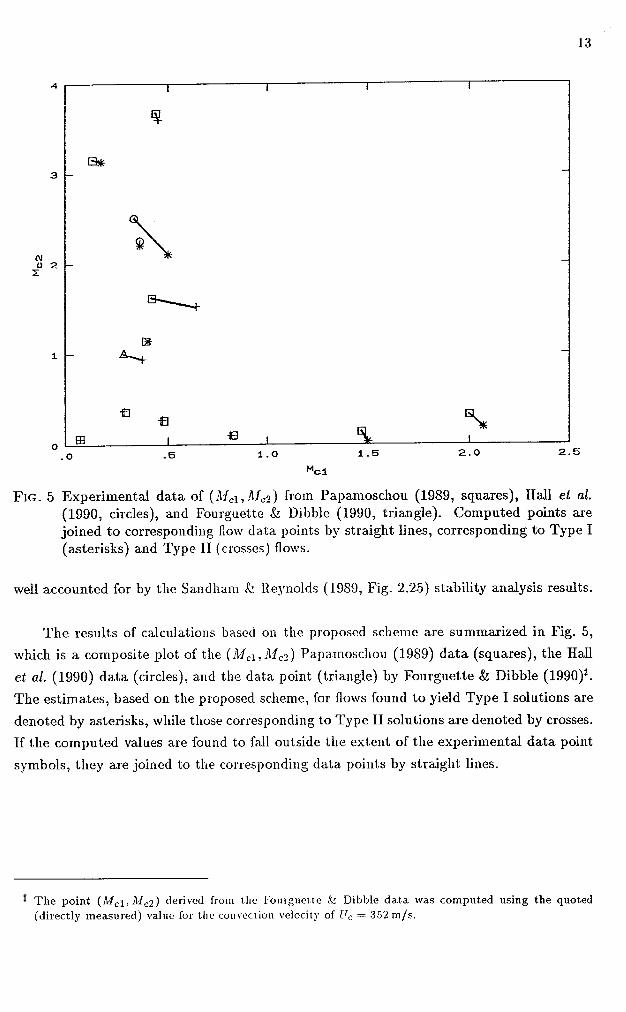
FIG. 5 Experiinental data of (:Ifcl, .!Ifc2) from Papamoscl~ou (1989, squares), Hall et aE. (1990, circles), and Fourguctt.e & Dibble (1990, triangle). Conlputed points are joined to correspondiilg flow data points by straight lines, corresponding to Type I (asterisks) and Type I1 (crosses) floxsls.
well accounted for by the Salldllam k lieynolds (1989, Fig. 2.25) stability analysis results.
The resu1t.s of calculastio~~s based on the proposed scheme are summarized in Fig. 5,
which is a composite plot of the (Adcl, df,?) Papainoscliou (1989) data (squares), the Hall
et a.2. (1990) da.ta (circles), and the data. point (triangle) by Fourguette & Dibble (1990)~.
The estima.tes, based oil the proposed scheme, for flows found to yield Type I solutions are
denoted by asterisks, while those corresponding to Type I1 solutions are denoted by crosses.
If the colnputed values a.re found to fall outside the estent of the experimental data point
symbols, they are joiilcd to the corresponding da.ta. points by straight lines.
fl T h e point (Adc1, Mc2) derived froin tlle F011rgl1et.t.e k Dibble da.t.a was computed using the quoted (directly measured) val~ie for the col~\rectioll velocity of Clc = 352 m/s.

Discussion and conclusions
It would appear that the proposed ansatz of a ~110cli strength that renders the flow
stationary, coupled with the two selection rules, i.e. of Type I over Type I1 branches (if both
are present) and the choice of the solution that yields the lower stagnation pressure (if more
than one solution is possible), correctly accounts for the stream that carries the shocks and
provides reasonable quantitative estimates for the observed values of the convective Mach
number. The proposal of stationarity for supersonic flow is also interesting in that it has
no counterpart in subsonic, isentropic flow. The latter has no additional free parameter in
satisfying the pressure matching condition.
It should be noted that it is more than liliely that the flow may be characterized by
hysteresis effects. As flow conditions may gradually change from one set of parameters to
another, the flow configuration and when the jumps would occur is likely to depend on
the history of these cha.ilges. If the shocks are borne by one of the two free streams, for
example, it is likely that they will persist in the sane stream beyond the point where a
different solution, in which, say, the shocks are borne by the opposite free stream, may be
indicated at the new flow conditions.
Some of the implications of these results call be appreciated in the context of the
discussion on shear layer entraininent outlined in the introduction. These points will be
illustrated using the values derived from the experimental data and the results of these
calculations for the Hall et al. (1990) supersonic shear layer data (AJ1 = 1.5[He], A12 =
0.3 [ N z ] ) , as an example. For this s11ea.r la.yer, we might have predicted a relative velocity
ratio, based on isentropic estima.tes*, of
Instead. we have
using the convection velocity estimate of U, = 8SO~n/s that is suggested by the data and
also derived using the scheme proposed here. Ignoring, for the moment, the near unity
(I f l l z ) factor in Eq. 1, stemn~jng fsom the spatial grotvth of the layer, this implies that
such a layer, rather than being high speed fluid riclz with a mean volumetric mixture ratio
of high speed fluid to low speed fluid of roughly 2:1, can be expected to be low speed fluid
rich with a volunletric ratio of roughly 1:3. There is almost a factor of 6 difference between
the two estimates. Restoriilg the spatial groivth factor in these calculatioils would result in
small changes in the individlial estimates, but would not substa-ntially alter their ratio.
( 4 * Recall Eq. 1 and related discussion and that dlcl /df!j) = 0.91Tj0.983 for t,his flow (see p. 10).

Accepting the proposed schelne a.nd the proposals on entrainment t11a.t were outlined
in the introduction at face value leads to some interesting implications for practical ap-
plications. Specifica.lly, in addition to the asymnletries in entrainment that the data have
already suggested should be anticipa.ted, the proposed model further suggests that even
sinall changes in the free stream paranleters may be responsible for changiilg the stream
that carries the shocks, under soine flow conditions. Under these circuinstances, gradual
changes in the flow pa.raillet.ers axe predicted to be potentially responsible for jumps in the
flow configuration. In some ca.ses, such large cha.nges (jumps) in the flow configuration
are predicted to occur as a result of only small changes in flow velocity, composition, or
stagnation temperature in one of the free streams. Such jumps would be responsible for
correspondingly 1a.rge cha.nges in entrainment and, in turn, cha.nges of the composition,
cheinical environment, cheinica.1 product forillation and 11ea.t release in a combusting shear
layer.
Acknowledgements
I would like to a.cknowledge many useful discussions wit11 Prof. Dale Pullin which
occurred in the course of the formulation of these ideas. I would also like to acknowledge
the discussions with Jeff Hall and Hcnning R.osemann, which helped identify the coding
error in the iinplementation of the previous analysis (Dinlotalcis 1989), and the suggestions
with the text by Paul Miller. This work was supported by the Air Breathing Propulsion
program of the Air Force Ofiice of Scientific Research, Grant No. 88-0155.

References
BOGDANOFF, D. W. [1983] "Compressibility Effects in Turbulent Shear Layers", (TN)
AIAA J. 21(6), 926-927.
BROWN, G. L. and ROSHICO, A. [I9741 "On Density Effects and Large Structure in
Turbulent Mixing Layers", J . Fluid Alech. 64(4), 775-816.
CLEMENS, N. T., MUNGAL, h4. G., BERGER, T. E. and VANDSBURGER, U. [I9901 "Vi-
sualizations of the structure of the turbulent mixing layer under compressible conditions",
AIAA 28th Aerospace Sciences Meeting, 8-11 January 1990 (Reno, Nevada), pa.per AIAA-
90-0500.
CLEMENS, N. T. and MUNGAL, hii. G. [1990] "Two- and Three-Dilnensional Effects in
the Supersonic Mixing La.yerV ,26"' AIAA4/SA E/ASAlE/ASEE Joint Propulsion Conference
(Orlando, FL), 10-12 July 1990, AIAi-90-1978.
COLES, D. [I9551 "Dryden Lecture: The Uses of Coherent Structure", AIAA 23rd
Aerospace Sciences Meeting, 14-17 January 1985 (Reno, Nevada), AIAA Paper 85-0506.
DIMOTAI<IS, P. E. [I9841 "Two-dimensional shear-layer entrainment", AIAA 22nd Aero-
space Sciences Meeting, 9-12 Ja.nuasy 1984 (Reno, Nevada), AIAA-84-0368. Published,
AIAA J. 24(11), 1791-1796 (1986).
DIMOTAICIS, P. E. [I9891 "Turbulent Free Shear Layer h/Iising", AIAA 27th Aerospace
Sciences Meeting, 9-12 January 1989 (R.eno, Nevada), AIAA-89-0262.
FERRI, A. [I9731 'LMisii~g-Coi~t~rolled Supersonic Combustion", Ann. Rev. Fluid Mech.
5, 301-338.
FERRI, A., LIBBY, P. A. aad ZAICKAY, V. [1962] "Theoretical and Experimeiltal Investi-
gation of Supersonic Combustioi~", Proc. 3rd ICAS Congress, Stocl<holm, (Spartan Bool;s,
Wash. DC), 1089-1155.
FOURGUETTE, D. and DIBBLE, R . [l990] "Time Evolution of the Shear Layer of a Super-
sonic Jet a t Ma.tched Conditions", A1.4-4 28''' Aerospace Sciences AIeetiag, 8-11 January
1990 (Reno, Nevada.), AIAA-90-0508.
JACICSON, T. L. and G ~ o s c r i , C. 12. [I9881 "Spatial Sta.bility of a Compressible Mixing
Layer", NASA ICASE Report No. 83-33.
JACICSON, T. L. and GROSCII , C1. E. [I9901 "Inviscid spa.tia1 stability of a compressible
mixing layer", J. Fluid Afech. 208, 609-637.

JACKSON , T. L. and GROSCH , C. E. [1990] "Absolute/convective instabilities and the
convective nlach number in a compressible mixing layer", Plzys. Fluids A 2(6), 949-954.
LIEPMANN, H. W. and R o s ~ r ~ o , A. [I9571 Elements of Gasdyl~amics (GALCIT Aero-
nautical Series, Jo1111 Wiley k Sons, Inc.).
LELE, S. I<. [I9891 "Direct Nunlerical Simulation of Con~pressible Free Shear Flows",
AIAA 27t" Aerospace Sciences hfeetillg, 9-12 January 1989 (R.eno, Nevada), AIAA Paper
89-0374.
LOWSON, h4.. V. and OLLERHEAD, J. B. [I9681 "Visualization of noise from cold super-
sonic jets", J. Acoust. Soc, All?. 44, 624.
HALL, J. L., DIMOTAKIS, P. E. and R.OSEMANN, H. [1990] "Experiments in non-reacting
compressible shear layers", abstract sub~nitted for the AIAA 2gth Aerospace Sciences
Meeting, 7-10 January 1991 (Reno, Nevada).
PAPAMOSCHOU , D. [I9891 "Structure of the compressible turbulent shear layer", AIAA
27th Aerospace Sciences Afeeting, 9-12 Jailuary 1989 (Reno, Nevada), AIAA Paper 89-
0126.
PAPAMOSCHOU, D. and ROSHI ;~ , A. [I9881 "The Compressible Turbulent Shear Layer:
An Experimental Study", J. Fluid Ilfech. 197, 453-477.
RAGAB, S. A. and W U , J. L. [1989a] "Lii1ea.r instabilities in two-dimeasional compressible
mixing layers", Pliys. Fluids A 1(6), 957-966.
RAGAB, S. A. and Wu, J. L. [1989b] "Linear Instability \Vaves in Supersonic Turbulent
h$ising Layers", AL4A J. 2 7(6), 677-686.
SANDHAM, N. a.nd R.EYNOLDS, \V. C. [1989a] "The Compressible Mixing La.yeer Linear
Theory and Direct Simula.t.ion7', -4I-4A 2Ph Aerospace Scielzces Meeting, 9-12 January
1989 (Reno, Nevada), AIAA-89--0371.
SANDHAM, N. D. and REYNOLDS, \V. C. [1989b] "A Numerical Investigation of the
Conlpressible Mixing La.yer7', St anford R.epor t TF-4.5.
SANDHAM, N. D. and R.EYNOLDS, W. C. [1990] "Compressible Mixing Layer: Linear
Theory and Direct Sin~ula.tion", AIL4A J. 28(4), 618-624.
TAM, C. I<. W. [1971] "DirectionaJ a.coust.ic ra.dia.tion from a supersollic jet", J. Fluid
Mech. 46(4), 757-763.
TAM, C. I<. 147. a.nd I-Irr , F. Q. [I9881 "Instabilities of supersonic mixing 1a.yers inside
a rectangular channel", Proceedings, First hra,tional Fluid Dyrzalnics Congress, 25-28 July
1988 (Cincinatti, Ohio), 11, 1073-1086.
TAM, C. I<. IV. and I-Iu, F. Q. [1989] "The instability and acoustic wave modes of
supersonic mixing layers inside a. recta.ngular cl~a.nnel", J . Fluid A,fech. 203, 51-76.
ZHUANG, M., I<UBOTA, T. and DIMOTAKIS, P. E. [1988] "On the Stability of Inviscid,
Colnpressible Free Shear Layers", Proceedings, First National Fluid Dynamics Congress,
25-28 July 1988 (Cincinatti, Ohio), 11, 768-773.
ZAUANG, M., DIMOTAI~IS, P. E. a.nd I<UBOTA, T. [1990] "The Effect of Walls on a
Spatially Growing Supersonic S1~ea.r Layer", Plljfs. Fluids A 2(4), 599-604.