grade level spill containment manholes - franklin · pdf filegrade level spill containment...
TRANSCRIPT
Grade Level Spill Containment ManholesInstallation Instructions
705 - 5 Gallon 715 - 15 Gallon 725 - 25 Gallon
Franklin Fueling Systems • 3760 Marsh Rd • Madison, WI 53718 USA
Tel: +1 608 838 8786 • 800 225 9787 • Fax: +1 608 838 6433 • www.franklinfueling.com
Manual # Revision Date Changes from Previous RevisionF-1307 7 Mar. 2012 Removed reference to pipe sealant brand
2
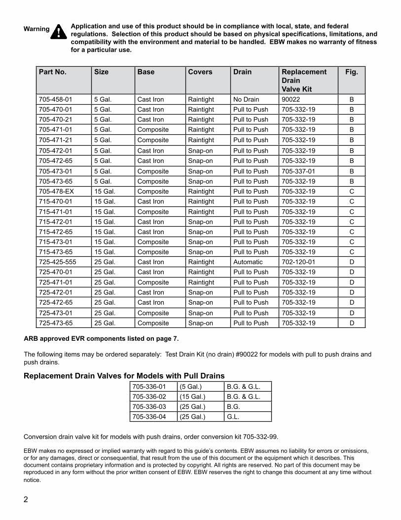
Part No. Size Base Covers Drain Replacement Drain Valve Kit
Fig.
705-458-01 5 Gal. Cast Iron Raintight No Drain 90022 B705-470-01 5 Gal. Cast Iron Raintight Pull to Push 705-332-19 B705-470-21 5 Gal. Cast Iron Raintight Pull to Push 705-332-19 B705-471-01 5 Gal. Composite Raintight Pull to Push 705-332-19 B705-471-21 5 Gal. Composite Raintight Pull to Push 705-332-19 B705-472-01 5 Gal. Cast Iron Snap-on Pull to Push 705-332-19 B705-472-65 5 Gal. Cast Iron Snap-on Pull to Push 705-332-19 B705-473-01 5 Gal. Composite Snap-on Pull to Push 705-337-01 B705-473-65 5 Gal. Composite Snap-on Pull to Push 705-332-19 B705-478-EX 15 Gal. Composite Raintight Pull to Push 705-332-19 C715-470-01 15 Gal. Cast Iron Raintight Pull to Push 705-332-19 C715-471-01 15 Gal. Composite Raintight Pull to Push 705-332-19 C715-472-01 15 Gal. Cast Iron Snap-on Pull to Push 705-332-19 C715-472-65 15 Gal. Cast Iron Snap-on Pull to Push 705-332-19 C715-473-01 15 Gal. Composite Snap-on Pull to Push 705-332-19 C715-473-65 15 Gal. Composite Snap-on Pull to Push 705-332-19 C725-425-555 25 Gal. Cast Iron Raintight Automatic 702-120-01 D725-470-01 25 Gal. Cast Iron Raintight Pull to Push 705-332-19 D725-471-01 25 Gal. Composite Raintight Pull to Push 705-332-19 D725-472-01 25 Gal. Cast Iron Snap-on Pull to Push 705-332-19 D725-472-65 25 Gal. Cast Iron Snap-on Pull to Push 705-332-19 D725-473-01 25 Gal. Composite Snap-on Pull to Push 705-332-19 D725-473-65 25 Gal. Composite Snap-on Pull to Push 705-332-19 D
ARB approved EVR components listed on page 7.
The following items may be ordered separately: Test Drain Kit (no drain) #90022 for models with pull to push drains and push drains.
Replacement Drain Valves for Models with Pull Drains705-336-01 (5 Gal.) B.G. & G.L.705-336-02 (15 Gal.) B.G. & G.L.705-336-03 (25 Gal.) B.G.705-336-04 (25 Gal.) G.L.
Conversion drain valve kit for models with push drains, order conversion kit 705-332-99.
EBW makes no expressed or implied warranty with regard to this guide’s contents. EBW assumes no liability for errors or omissions, or for any damages, direct or consequential, that result from the use of this document or the equipment which it describes. This document contains proprietary information and is protected by copyright. All rights are reserved. No part of this document may be reproduced in any form without the prior written consent of EBW. EBW reserves the right to change this document at any time without notice.
Application and use of this product should be in compliance with local, state, and federal regulations. Selection of this product should be based on physical specifications, limitations, and compatibility with the environment and material to be handled. EBW makes no warranty of fitness for a particular use.
Warning

3
Grade Level Spill Containment Manholes705, 715, 725-GL (5,15, & 25 Gallon)
Installation InstructionsBefore installing a spill container, coat all of the riser pipe threads with a thread sealant that is compatible with the product in that tank.
Install the spill container by threading it onto the tank riser pipe until it is hand tight. Do not use the upper cast iron ring to fully tighten the container. Tightening the tank using the upper cast iron ring can cause undue stress to the entire unit.
After hand tightening, place a torque wrench assembly around the lower portion of the tank base and torque the spill bucket base on a riser pipe to 60 - 90 ft. lbs. torque using an EBW chain wrench (part #901-101-01) and a torque wrench with at least 100 ft. lbs. of torque range (due to an offset of chain and torque wrenches, actual torque wrench values will be 45 - 70 ft. lbs.). After an initial torque value is obtained, continue to thread the tank base onto the riser pipe until the drain valve is orientated to the riser low spot.
Note: All of the tank risers have some out-of-plumb characteristics due to slight tank tilts and rolls. To properly drain, the drain valve must be located at the low spot of the riser tilt. The riser low spot is the direction the riser pipe is leaning towards. This is easily obtained by placing a small amount of water in the bucket base and turning the bucket until the water runs to the drain valve.
If space is limited (i.e. a retrofit installation to a sawed out section of concrete):
1) Make sure that the inside riser pipe is removed.2) Locate the fitting that the inside riser pipe threads
into.3) Coming down through the top of the unit, use a
special socket wrench on the octagonal surface of the fitting to finish tightening it. Do not disassemble the unit.
• The top edge of the rim must be positioned a minimum of 2" above the driveway level to provide an adequate slope for drainage.
• Before pouring cement, place duct tape around the rim, this will keep the cement out of the drainage grooves when the lid is in place. See figure A. After cement has solidified, remove any duct tape or excess cement.
Note: If you want to seal off a drain to test your unit, install a test drain kit (part #90022-01).
Check For LeaksEvery unit should be tested for leaks prior to, and after, pouring concrete. If this model comes with a drain, close it. If not, install a 90022-01 test drain kit. Fill the unit completely with water. If the test water level drops at all within one hour, then a leak exists (this is not an EVR test).
Check to see that the drain valve is seated properly. If not, then PULL the drain valve several times on a PULL TO PUSH DRAIN UNIT. Replace the valve if it continues to leak.
If the unit continues to leak, the entire spill container must be removed from the riser pipe and replaced with another. RE-TEST.
After backfilling the area with pea gravel and pouring concrete, RE-TEST to make sure that no damage occurred during installation.
Figure A: Protect drainage grooves
Duct Tape
Lid
Concrete Drive
4
Grade
17.00"Composite
Base
15.88"Cast Iron
Base
13.06"
17.12" Ring Adapter Width
4.00"
This surface should be sloped 1" fromgrade or per customer specifications
3.5” minimum to allow for fillcap and tank movement.
Cast Lug
Cast Iron Ring
Insulation
Concrete Drive
Gravel Guard
Octagonal Surface
Round Surface
PeaGravel
Fill
Length of riserpipe to be determined bycontractor in the field Note: Location of drain valve
assy. or test plug.
1.00"
15.88"Dia.Concrete Drive
PeaGravel
Fill
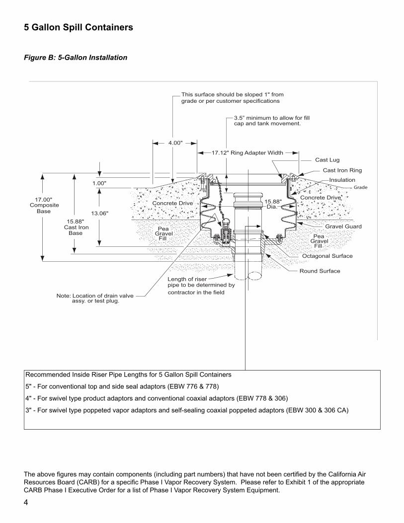
Figure B: 5-Gallon Installation
The above figures may contain components (including part numbers) that have not been certified by the California Air Resources Board (CARB) for a specific Phase I Vapor Recovery System. Please refer to Exhibit 1 of the appropriate CARB Phase I Executive Order for a list of Phase I Vapor Recovery System Equipment.
5 Gallon Spill Containers
Recommended Inside Riser Pipe Lengths for 5 Gallon Spill Containers
5" - For conventional top and side seal adaptors (EBW 776 & 778)
4" - For swivel type product adaptors and conventional coaxial adaptors (EBW 778 & 306)
3" - For swivel type poppeted vapor adaptors and self-sealing coaxial poppeted adaptors (EBW 300 & 306 CA)
5
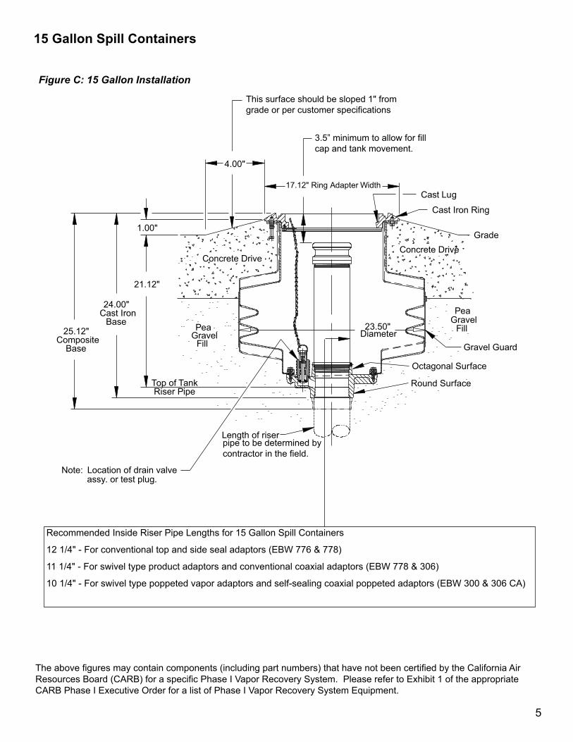
Figure C: 15 Gallon Installation
The above figures may contain components (including part numbers) that have not been certified by the California Air Resources Board (CARB) for a specific Phase I Vapor Recovery System. Please refer to Exhibit 1 of the appropriate CARB Phase I Executive Order for a list of Phase I Vapor Recovery System Equipment.
15 Gallon Spill Containers
Recommended Inside Riser Pipe Lengths for 15 Gallon Spill Containers
12 1/4" - For conventional top and side seal adaptors (EBW 776 & 778)
11 1/4" - For swivel type product adaptors and conventional coaxial adaptors (EBW 778 & 306)
10 1/4" - For swivel type poppeted vapor adaptors and self-sealing coaxial poppeted adaptors (EBW 300 & 306 CA)
This surface should be sloped 1" from grade or per customer specifications
3.5” minimum to allow for fillcap and tank movement.
Cast Lug
Cast Iron Ring
GradeConcrete Drive
Gravel Guard
Octagonal Surface
Round Surface
23.50" Diameter
Length of riserpipe to be determined bycontractor in the field.
Note: Location of drain valve assy. or test plug.
Top of TankRiser Pipe
21.12"
24.00"Cast Iron
Base25.12"
CompositeBase
1.00"
4.00"
17.12" Ring Adapter Width
PeaGravel
Fill
Concrete Drive
PeaGravel
Fill
6
This surface should be sloped 1" fromgrade or per customer specifications
3.5" minimum to allow for fill cap and tank movement.
Cast Lug
Cast Iron Ring
Grade
Concrete Drive
Gravel Guard
Octagonal Surface
Round Surface
27.00" Diameter
Length of riserpipe to be determined bycontractor in the field. Note: Location of drain valve
assy. or test plug.
Top of TankRiser Pipe
21.12"
24.00"Cast Iron
Base
25.12"Composite
Base
1.00"
4.00"17.12" Ring Adapter Width
PeaGravel
Fill
Concrete Drive
PeaGravel
Fill
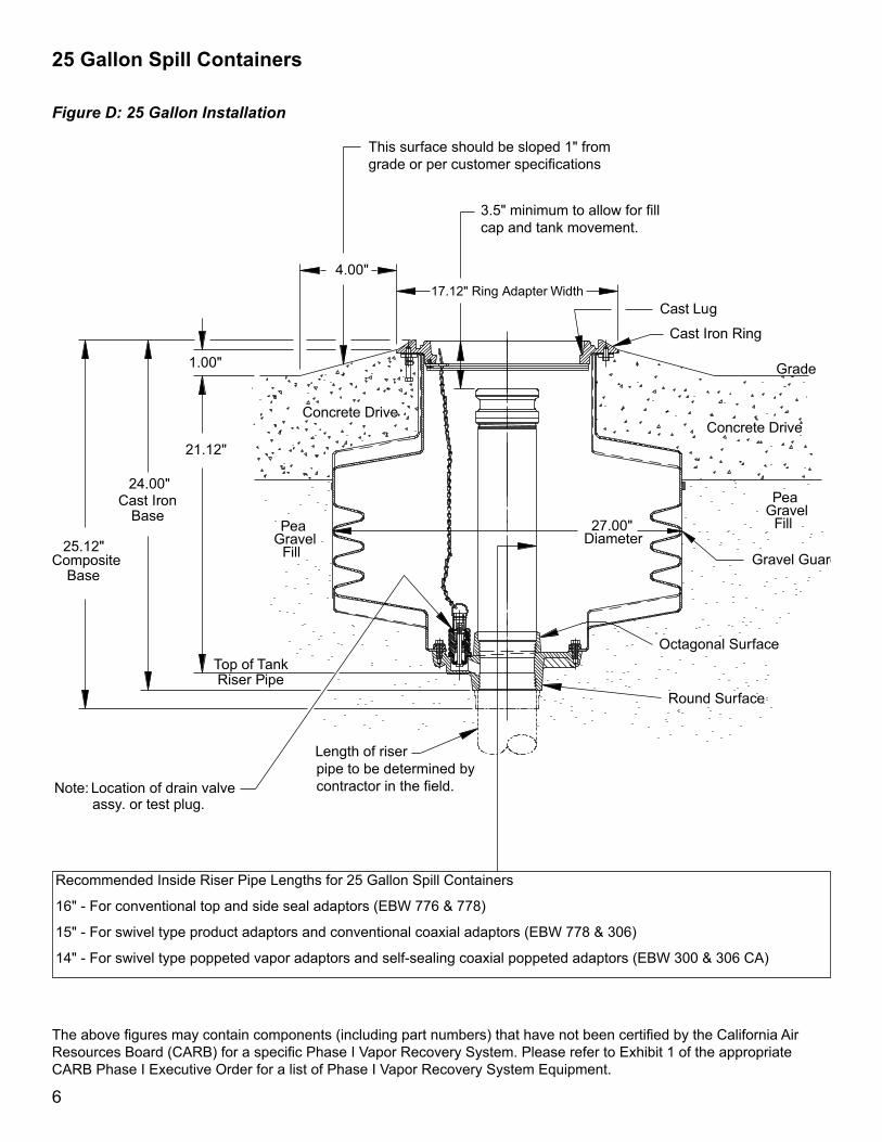
25 Gallon Spill Containers
The above figures may contain components (including part numbers) that have not been certified by the California Air Resources Board (CARB) for a specific Phase I Vapor Recovery System. Please refer to Exhibit 1 of the appropriate CARB Phase I Executive Order for a list of Phase I Vapor Recovery System Equipment.
Recommended Inside Riser Pipe Lengths for 25 Gallon Spill Containers
16" - For conventional top and side seal adaptors (EBW 776 & 778)
15" - For swivel type product adaptors and conventional coaxial adaptors (EBW 778 & 306)
14" - For swivel type poppeted vapor adaptors and self-sealing coaxial poppeted adaptors (EBW 300 & 306 CA)
Figure D: 25 Gallon Installation

7
Part No. Size Base Covers Drain Replacement Drain Valve Kit Fig.705-490-01 5 Gal. Cast Iron Raintight Pull to Push 705-337-19 B705-490-02 5 Gal. Cast Iron Raintight No Drain B705-490-03 5 Gal. Cast Iron Watertight Pull to Push 705-337-19 B705-490-04 5 Gal. Cast Iron Watertight No Drain B705-491-01 5 Gal. Composite Raintight Pull to Push 705-337-19 B705-491-02 5 Gal. Composite Raintight No Drain B705-491-03 5 Gal. Composite Watertight Pull to Push 705-337-19 B705-491-04 5 Gal. Composite Watertight No Drain B715-490-01 15 Gal. Cast Iron Raintight Pull to Push 705-337-19 C715-490-02 15 Gal. Cast Iron Raintight No Drain C715-490-03 15 Gal. Cast Iron Watertight Pull to Push 705-337-19 C715-490-04 15 Gal. Cast Iron Watertight No Drain C715-491-01 15 Gal. Composite Raintight Pull to Push 705-337-19 C715-491-02 15 Gal. Composite Raintight No Drain C715-491-03 15 Gal. Composite Watertight Pull to Push 705-337-19 C715-491-04 15 Gal. Composite Watertight No Drain C725-490-01 25 Gal. Cast Iron Raintight Pull to Push 705-337-19 D725-490-02 25 Gal. Cast Iron Raintight No Drain D725-490-03 25 Gal. Cast Iron Watertight Pull to Push 705-337-19 D725-490-04 25 Gal. Cast Iron Watertight No Drain D725-491-01 25 Gal. Composite Raintight Pull to Push 705-337-19 D725-491-02 25 Gal. Composite Raintight No Drain D725-491-03 25 Gal. Composite Watertight Pull to Push 705-337-19 D725-491-04 25 Gal. Composite Watertight No Drain D
Monthly Recommended Maintenance & Inspection Procedures1. Clean/Remove any buildup of sand, gravel, or dirt from the manhole top cast flange. Buildup of material will
prevent the manhole lid from sitting flat and diverting rain water. In addition to water infiltration, this can lead to premature lid failures and tripping hazards.
2. Inspect the spill container latching mechanism and make sure that it is operating properly.3. Inspect the hinged cover gasket and replace it if necessary.4. Inspect the spill container for the presence of liquid. If any is present, identify the material (water or fuel) and
dispose of it using your preferred acceptable method (pump it out or drain it into the tank).5. Inspect the spill container and the drain valve screen for any foreign material collecting in the bottom of the tank.
Remove any large objects (leaves, rags, etc.) and wipe the bottom of the tank with a disposable rag.6. Inspect the tank riser adapter and the dust cap for obvious damage. Verify that the gasket is in the dust cap and
that the dust cap still securely latches onto the adapter.
Post Installation Inspection ProcedureAfter installing these spill containers, but prior to backfilling the excavation, EBW recommends that the tank system be checked for potential leaks. In CA, utilize TP-201.3, Static Pressure Test Procedure. In other areas, utilize this or a locally approved/accepted pressure test procedure. Should a leak be present, test the following with an acceptable leak check fluid: the tank and spill container piping joints, the drain valve poppet and gasket, the permanent drain blank plate gasket, and the adapter piping joint. Repair all of the leaks prior to backfilling.
C.A.R.B. Approved Below Grade Spill Containers

Composite Base Spill ContainmentInstallation Instructions
1. Before installing a spill containment manhole, apply PTFE thread sealant tape clockwise around the riser pipe threads.
2. Align the composite base on the riser pipe as shown in Figure E.3. Rotate the spill containment counter clockwise until the threads mesh (you can feel the unit drop into place), then
rotate it clockwise until it is handtight.
4. To finish tightening, refer to Figure F and check p. 3 for torque specifications.5. Continue with the standard instructions for setting the top rim to driveway grade level.
Figure E
Do not use the upper cast iron ring to fully tighten the spill containment tank. Tightening the tank using the upper cast iron ring can cause undue stress to the entire unit.
Caution
Figure F
©2012 EBW Form No. 1307 Rev. 7
Riser pipe
Composite Base