gps pseudolites - computer engineering and networks laboratory
TRANSCRIPT

SUDAAR 707
GPS PSEUDOLITES:
THEORY, DESIGN, AND APPLICATIONS
A DISSERTATION
SUBMITTED TO THE DEPARTMENT OF AERONAUTICS AND ASTRONAUTICS
AND THE COMMITTEE ON GRADUATE STUDIES
OF STANFORD UNIVERSITY
IN PARTIAL FULFILLMENT OF THE REQUIREMENTS
FOR THE DEGREE OF
DOCTOR OF PHILOSOPHY
H. Stewart Cobb
September 1997

c© Copyright 1997
by
H. Stewart Cobb
ii

I certify that I have read this dissertation and that in my
opinion it is fully adequate, in scope and in quality, as a
dissertation for the degree of Doctor of Philosophy.
Bradford W. Parkinson(Principal Advisor)
I certify that I have read this dissertation and that in my
opinion it is fully adequate, in scope and in quality, as a
dissertation for the degree of Doctor of Philosophy.
J. David Powell
I certify that I have read this dissertation and that in my
opinion it is fully adequate, in scope and in quality, as a
dissertation for the degree of Doctor of Philosophy.
Per K. Enge
Approved for the University Committee on Graduate Studies:
Dean of Graduate Studies
iii

�
iv

Abstract
Pseudolites (ground-based pseudo-satellite transmitters) can initialize carrier-phase differ-
ential GPS (CDGPS) navigation systems in seconds to perform real-time dynamic posi-
tioning with 1σ errors as low as 1 cm. Previous CDGPS systems were rarely used due
to cumbersome initialization procedures requiring up to 30 minutes; initialization of the
carrier-phase integer ambiguities via pseudolite removes these constraints. This work de-
scribes pseudolites optimized for this application which cost two orders of magnitude less
than previous pseudolites.
Synchrolites (synchronized pseudolites), which derive their timing from individual Glo-
bal Positioning System (GPS) satellites, are also described. Synchrolites can replace the
CDGPS reference station and datalink, while simultaneously serving to initialize CDGPS
navigation. A cluster of well-placed synchrolites could enable CDGPS navigation even if
only one GPS satellite signal is available.
A prototype CDGPS system initialized by pseudolites and synchrolites was designed and
tested. The goal of this system, known as the Integrity Beacon Landing System (IBLS),
was to provide navigation accurate and reliable enough to land aircraft in bad weather.
Flight test results for prototype pseudolite and synchrolite systems, including results from
110 fully automatic landings of a Boeing 737 airliner controlled by IBLS, are presented.
Existing pseudolite applications are described, including simulation of the GPS constel-
lation for indoor navigation experiments. Synchrolite navigation algorithms are developed
and analyzed. New applications for pseudolites and synchrolites are proposed. Theoretical
and practical work on the near/far problem is presented.
v

�
vi

Acknowledgements
This research would not have been possible without the efforts of a large number of other
people. Foremost among these is my advisor, Professor Brad Parkinson, who guided the
original development of GPS two decades ago and arranged the funding which made this
research possible. I have learned technology, leadership, and management from him. Pro-
fessor David Powell equipped his own Piper Dakota (N4341M) to support this research,
and piloted it many times for flight tests. On the ground, he taught me dynamics and
control theory. Professor Per Enge guided me through the finer points of electrical engi-
neering and estimation theory. Professors Jonathan How and Donald Cox heard, analyzed,
and approved my thesis defense. Thanks to all of these for their expertise, friendship, and
support.
The other three members of the original IBLS team were Clark Cohen, David Lawrence,
and Boris Pervan. Clark originated the IBLS concept, Boris created the integer initialization
algorithm, and Dave wrote the real-time navigation algorithm and analyzed the data. As a
team, we shared successes and setbacks, design and redesign, long discussions, long journeys,
and long hours. In the end, teamwork triumphed over all the obstacles we faced.
Other members of the GPS group donated their time and efforts to this research when-
ever necessary. Andy Barrows debugged the radio datalinks, then went to Germany as the
IBLS advance man. Gabe Elkaim proved to be an expert at both digging holes and getting
permission to dig them. Konstantin Gromov helped build modulators, interfaces, and many
other bits of hardware and software required in the course of this research. Renxin Xia de-
signed the circuitry inside the programmable logic chip that was the heart of the simple
pseudolite. Chris Shaw designed and built the weatherproof pseudolite housings and their
mounts. Todd Walter and Changdon Kee offered design ideas and advice. Jock Christie,
Mike O’Connor, Jennifer Evans, Y. C. Chao, and many others helped load, move, install,
and retrieve the mountain of equipment required for each test. To all of these, many thanks.
vii

Thanks also to Kurt Zimmerman, Paul Montgomery, Jonathan Stone, Carole Parker, and
Mike Ament for suggesting improvements to this dissertation.
The test pilots, who chose to risk their nerves and perhaps their lives advancing the state
of the art, included Keith Biehl at the FAA, Bill Loewe of United Airlines, Manfred Dieroff of
T. U. Braunschwieg, and the previously-mentioned David Powell. Steve Kalinowski, Mark
Ostendorf, Lutz Seiler, and the people of Elsinore Aerospace helped install IBLS on various
aircraft while keeping them flightworthy. Victor Wullschleger at the FAA, Gerry Aubrey of
United, and Andreas Lipp at T. U. Braunschweig arranged for their institutions to sponsor
our flight tests. Without the diligent efforts of all these people, the IBLS experiments never
would have gotten off the ground.
Flight tests cannot take place without airplanes, and airplanes cannot fly for long with-
out mechanics. Thanks to Alberto Rossi and his co-workers at PAO, the FAA’s mechanics
at ATC, the United maintenance crews at SFO, and the Aerodata team at BWE. Their
hard work kept us all safe in the air.
The GP-B office staff gave me an enormous amount of support. Denise Freeman shot
many of the photographs which appear on these pages. Sally Tsuchihashi, Mindy Lumm,
and Jennifer Gale-Messer brightened my days while keeping me in touch with the rest of
the universe.
Trimble Navigation allowed us to purchase their receivers at a discount and modify their
receiver software to track pseudolites. The FAA funded most of this research under grant
number 93G004. Earlier work was performed under NASA grant number 188N002.
Finally, I’d like to thank my family. My parents, Hank and Mary Jane, nurtured a small
spark of inquisitiveness and fanned it into a flame with toys, tools, and books. My two
brothers, Mitchell and Tucker, helped me along with fellowship, guidance, and sympathy—
or lack thereof—as necessary. I couldn’t have done this without their support. Thanks,
y’all, more than I can say.
viii

Contents
Abstract v
Acknowledgements vii
1 Introduction 1
1.1 Motivation . . . . . . . . . . . . . . . . . . . . . . . . . . . . . . . . . . . . 2
1.2 Background . . . . . . . . . . . . . . . . . . . . . . . . . . . . . . . . . . . . 4
1.3 Previous Work . . . . . . . . . . . . . . . . . . . . . . . . . . . . . . . . . . 7
1.4 Contributions . . . . . . . . . . . . . . . . . . . . . . . . . . . . . . . . . . . 9
1.5 Nomenclature . . . . . . . . . . . . . . . . . . . . . . . . . . . . . . . . . . . 11
1.6 Outline of this Dissertation . . . . . . . . . . . . . . . . . . . . . . . . . . . 11
2 Pseudolite Concepts 13
2.1 Code-phase GPS Navigation . . . . . . . . . . . . . . . . . . . . . . . . . . . 14
2.1.1 Pseudorange Measurements . . . . . . . . . . . . . . . . . . . . . . . 14
2.1.2 Navigation Algorithm . . . . . . . . . . . . . . . . . . . . . . . . . . 15
2.1.3 Direct Ranging Pseudolite . . . . . . . . . . . . . . . . . . . . . . . . 17
2.1.4 Mobile Pseudolite . . . . . . . . . . . . . . . . . . . . . . . . . . . . 19
2.2 Differential Code-phase GPS . . . . . . . . . . . . . . . . . . . . . . . . . . 20
2.2.1 Digital Datalink Pseudolite . . . . . . . . . . . . . . . . . . . . . . . 20
2.3 Carrier-phase Differential GPS Navigation . . . . . . . . . . . . . . . . . . . 21
2.3.1 Carrier-phase Ambiguity . . . . . . . . . . . . . . . . . . . . . . . . . 22
2.3.2 Carrier phase Ambiguity Resolution . . . . . . . . . . . . . . . . . . 24
2.3.3 Ambiguity Resolution using Pseudolites . . . . . . . . . . . . . . . . 25
2.4 Synchrolites . . . . . . . . . . . . . . . . . . . . . . . . . . . . . . . . . . . . 28
ix

2.4.1 Synchrolite Differential Measurements . . . . . . . . . . . . . . . . . 30
2.4.2 Synchrolite Reflection Delay . . . . . . . . . . . . . . . . . . . . . . . 32
2.4.3 Synchrolite Differential Navigation . . . . . . . . . . . . . . . . . . . 33
2.4.4 Geometry of Synchrolite Navigation . . . . . . . . . . . . . . . . . . 35
2.4.5 Synchrolite Navigation with Unknown Delays . . . . . . . . . . . . . 37
2.4.6 Operations with a Single Synchrolite . . . . . . . . . . . . . . . . . . 39
2.4.7 Operations with a Single Satellite . . . . . . . . . . . . . . . . . . . . 40
3 Practical Considerations 43
3.1 GPS Satellite Signals . . . . . . . . . . . . . . . . . . . . . . . . . . . . . . . 43
3.1.1 C/A Code Correlation Properties . . . . . . . . . . . . . . . . . . . . 46
3.1.2 Signal and Noise Power Levels . . . . . . . . . . . . . . . . . . . . . 47
3.1.3 Code Division Multiple Access (CDMA) . . . . . . . . . . . . . . . . 48
3.2 Near/Far Problem . . . . . . . . . . . . . . . . . . . . . . . . . . . . . . . . 49
3.3 Existing GPS Receivers . . . . . . . . . . . . . . . . . . . . . . . . . . . . . 51
3.4 Near/Far Tolerance . . . . . . . . . . . . . . . . . . . . . . . . . . . . . . . . 54
3.4.1 Trajectory Constraints . . . . . . . . . . . . . . . . . . . . . . . . . . 55
3.4.2 Antenna Patterns . . . . . . . . . . . . . . . . . . . . . . . . . . . . . 56
3.4.3 Separate Antennas . . . . . . . . . . . . . . . . . . . . . . . . . . . . 56
3.5 Near/Far Solutions . . . . . . . . . . . . . . . . . . . . . . . . . . . . . . . . 58
3.5.1 Out-of-Band Transmissions . . . . . . . . . . . . . . . . . . . . . . . 58
3.5.2 Frequency Offset . . . . . . . . . . . . . . . . . . . . . . . . . . . . . 59
3.5.3 Frequency Hopping . . . . . . . . . . . . . . . . . . . . . . . . . . . . 60
3.5.4 New Spreading Codes . . . . . . . . . . . . . . . . . . . . . . . . . . 62
3.5.5 Pulsed Transmissions . . . . . . . . . . . . . . . . . . . . . . . . . . 62
3.6 Pulsed Pseudolite Signals . . . . . . . . . . . . . . . . . . . . . . . . . . . . 62
3.6.1 Pulse Blanking . . . . . . . . . . . . . . . . . . . . . . . . . . . . . . 64
3.6.2 Receiver Saturation Characteristics . . . . . . . . . . . . . . . . . . . 64
3.6.3 Pulse Duty Cycles . . . . . . . . . . . . . . . . . . . . . . . . . . . . 67
3.6.4 Pulse Patterns . . . . . . . . . . . . . . . . . . . . . . . . . . . . . . 69
3.6.5 Mutual Interference . . . . . . . . . . . . . . . . . . . . . . . . . . . 71
3.7 New Spreading (PRN) Codes for Pseudolites . . . . . . . . . . . . . . . . . 73
3.7.1 Additional C/A Codes . . . . . . . . . . . . . . . . . . . . . . . . . . 74
x

3.7.2 Multi-Epoch C/A Codes . . . . . . . . . . . . . . . . . . . . . . . . . 74
3.7.3 Longer Codes . . . . . . . . . . . . . . . . . . . . . . . . . . . . . . . 75
3.7.4 Faster Codes . . . . . . . . . . . . . . . . . . . . . . . . . . . . . . . 75
3.7.5 P-codes . . . . . . . . . . . . . . . . . . . . . . . . . . . . . . . . . . 75
3.7.6 Polyphase Codes . . . . . . . . . . . . . . . . . . . . . . . . . . . . . 76
3.7.7 Analog Codes . . . . . . . . . . . . . . . . . . . . . . . . . . . . . . . 76
3.8 Phase Noise . . . . . . . . . . . . . . . . . . . . . . . . . . . . . . . . . . . . 77
3.9 Receiver Modifications . . . . . . . . . . . . . . . . . . . . . . . . . . . . . . 79
3.10 Recommended Receiver Improvements . . . . . . . . . . . . . . . . . . . . . 80
3.10.1 Code Phase Aiding . . . . . . . . . . . . . . . . . . . . . . . . . . . . 80
3.10.2 High Dynamic Range . . . . . . . . . . . . . . . . . . . . . . . . . . 80
3.11 Antennas . . . . . . . . . . . . . . . . . . . . . . . . . . . . . . . . . . . . . 81
3.12 Legality . . . . . . . . . . . . . . . . . . . . . . . . . . . . . . . . . . . . . . 82
3.13 Wisdom . . . . . . . . . . . . . . . . . . . . . . . . . . . . . . . . . . . . . . 84
4 Pseudolite Designs 87
4.1 Simple Pseudolite . . . . . . . . . . . . . . . . . . . . . . . . . . . . . . . . . 87
4.2 Pulsed Pseudolite . . . . . . . . . . . . . . . . . . . . . . . . . . . . . . . . . 94
4.3 Synchrolite . . . . . . . . . . . . . . . . . . . . . . . . . . . . . . . . . . . . 95
4.3.1 Autonomous Integrity Beacon (AIB) . . . . . . . . . . . . . . . . . . 96
4.3.2 Airport Pseudolite (APL) . . . . . . . . . . . . . . . . . . . . . . . . 98
4.3.3 Problems with the First Synchrolite . . . . . . . . . . . . . . . . . . 98
4.4 Synchrolite Improvements . . . . . . . . . . . . . . . . . . . . . . . . . . . . 99
4.5 Analog Synchrolites . . . . . . . . . . . . . . . . . . . . . . . . . . . . . . . 101
5 Pseudolite Flight Tests 103
5.1 Integrity Beacon Landing System (IBLS) . . . . . . . . . . . . . . . . . . . 103
5.1.1 Required Navigation Performance . . . . . . . . . . . . . . . . . . . 103
5.1.2 IBLS System Description . . . . . . . . . . . . . . . . . . . . . . . . 104
5.1.3 IBLS Flight Tests . . . . . . . . . . . . . . . . . . . . . . . . . . . . 106
5.2 Autonomous Integrity Beacon (AIB) . . . . . . . . . . . . . . . . . . . . . . 113
5.3 Pulsed Synchrolite (APL) . . . . . . . . . . . . . . . . . . . . . . . . . . . . 116
xi

6 Pseudolite Applications 121
6.1 Aircraft Applications . . . . . . . . . . . . . . . . . . . . . . . . . . . . . . . 121
6.1.1 Flight Inspection . . . . . . . . . . . . . . . . . . . . . . . . . . . . . 121
6.1.2 Accuracy in Thirteen Dimensions . . . . . . . . . . . . . . . . . . . . 122
6.2 Land Applications . . . . . . . . . . . . . . . . . . . . . . . . . . . . . . . . 124
6.2.1 Robotic Tractors . . . . . . . . . . . . . . . . . . . . . . . . . . . . . 124
6.2.2 Mining . . . . . . . . . . . . . . . . . . . . . . . . . . . . . . . . . . . 125
6.2.3 Automobiles . . . . . . . . . . . . . . . . . . . . . . . . . . . . . . . 126
6.2.4 Speculations . . . . . . . . . . . . . . . . . . . . . . . . . . . . . . . 126
6.3 Indoor Navigation . . . . . . . . . . . . . . . . . . . . . . . . . . . . . . . . 128
6.3.1 Space Robotics . . . . . . . . . . . . . . . . . . . . . . . . . . . . . . 128
6.3.2 Space Structures . . . . . . . . . . . . . . . . . . . . . . . . . . . . . 130
6.3.3 Speculations . . . . . . . . . . . . . . . . . . . . . . . . . . . . . . . 130
7 Conclusions 133
7.1 Results and Contributions . . . . . . . . . . . . . . . . . . . . . . . . . . . . 133
7.2 Recommendations for Future Research . . . . . . . . . . . . . . . . . . . . . 134
7.2.1 Synchrolite CDGPS Reference Station . . . . . . . . . . . . . . . . . 134
7.2.2 Multiple Synchrolite Navigation . . . . . . . . . . . . . . . . . . . . 135
7.2.3 Blanking Receivers . . . . . . . . . . . . . . . . . . . . . . . . . . . . 135
7.2.4 High Dynamic Range Receivers . . . . . . . . . . . . . . . . . . . . . 136
7.2.5 Near/Far Research . . . . . . . . . . . . . . . . . . . . . . . . . . . . 136
7.2.6 Higher Frequencies . . . . . . . . . . . . . . . . . . . . . . . . . . . . 136
7.2.7 Applications . . . . . . . . . . . . . . . . . . . . . . . . . . . . . . . 137
7.3 Summary . . . . . . . . . . . . . . . . . . . . . . . . . . . . . . . . . . . . . 137
A Glossary 139
B Hints for Designers 143
Bibliography 145
xii

List of Figures
1.1 The First Simple Pseudolite . . . . . . . . . . . . . . . . . . . . . . . . . . . 3
1.2 Approximate Accuracy of Civil GPS Navigation Modes . . . . . . . . . . . 4
2.1 GPS Navigation using Code Phase Pseudorange . . . . . . . . . . . . . . . . 15
2.2 Mobile Pseudolite . . . . . . . . . . . . . . . . . . . . . . . . . . . . . . . . . 19
2.3 Carrier-Phase Measurements and Integer Ambiguity . . . . . . . . . . . . . 23
2.4 Pseudolite Initializes CDGPS Carrier-phase Ambiguities . . . . . . . . . . . 26
2.5 Synchrolite Reflects Satellite Signals Coherently . . . . . . . . . . . . . . . . 29
2.6 Synchrolite Differential Pseudorange Measurement . . . . . . . . . . . . . . 30
2.7 Synchrolite DGPS Navigation Possibilities . . . . . . . . . . . . . . . . . . . 33
2.8 DGPS Positioning with Several Synchrolites . . . . . . . . . . . . . . . . . . 34
2.9 PDOP for Three Optimally Placed Synchrolites . . . . . . . . . . . . . . . . 36
2.10 DGPS Navigation Using a Single Synchrolite . . . . . . . . . . . . . . . . . 39
3.1 Spectrum of a C/A Code Signal . . . . . . . . . . . . . . . . . . . . . . . . . 45
3.2 Zones of the Near/Far Problem . . . . . . . . . . . . . . . . . . . . . . . . . 50
3.3 Side View of IBLS Flight Path over Pseudolite . . . . . . . . . . . . . . . . 55
3.4 Improving Near/Far Ratio with Antenna Patterns . . . . . . . . . . . . . . 57
3.5 Pseudolite Signal with Frequency Offset . . . . . . . . . . . . . . . . . . . . 59
3.6 Minimal Interference from Frequency Hopping Pseudolite . . . . . . . . . . 61
3.7 Pseudolite Pulses Affect Receiver AGC . . . . . . . . . . . . . . . . . . . . . 66
3.8 Pseudolite Pulse Duty Cycle Tradeoff . . . . . . . . . . . . . . . . . . . . . 69
4.1 Block Diagram of the Simple Pseudolite . . . . . . . . . . . . . . . . . . . . 88
4.2 Schematic Diagram of the Simple Pseudolite . . . . . . . . . . . . . . . . . . 89
4.3 An Assembled Simple Pseudolite (Actual Size) . . . . . . . . . . . . . . . . 90
xiii

4.4 The Simple Pseudolite in Operation . . . . . . . . . . . . . . . . . . . . . . 91
4.5 Output Spectrum of the Simple Pseudolite . . . . . . . . . . . . . . . . . . . 92
4.6 Housings for the Simple Pseudolite . . . . . . . . . . . . . . . . . . . . . . . 93
4.7 Block Diagram of the Pulsed Pseudolite . . . . . . . . . . . . . . . . . . . . 94
4.8 Block Diagram of the First Synchrolite . . . . . . . . . . . . . . . . . . . . . 96
4.9 The Autonomous Integrity Beacon (AIB) Synchrolite . . . . . . . . . . . . . 97
4.10 Output Spectrum of the First Synchrolite . . . . . . . . . . . . . . . . . . . 99
5.1 Overview of the Integrity Beacon Landing System (IBLS) . . . . . . . . . . 105
5.2 IBLS Flight Test Aircraft: Piper Dakota . . . . . . . . . . . . . . . . . . . . 107
5.3 IBLS Flight Test Aircraft: FAA King Air . . . . . . . . . . . . . . . . . . . 109
5.4 IBLS Flight Test Aircraft: Boeing 737 . . . . . . . . . . . . . . . . . . . . . 110
5.5 IBLS Vertical Navigation Sensor Error (VNSE) . . . . . . . . . . . . . . . . 111
5.6 IBLS Touchdown Box . . . . . . . . . . . . . . . . . . . . . . . . . . . . . . 112
5.7 Laser Tracker Errors during IBLS Autoland Test . . . . . . . . . . . . . . . 113
5.8 Histogram of Integer Differences during AIB Flight Tests . . . . . . . . . . 114
5.9 Testing the Airport Pseudolite (APL) Synchrolite . . . . . . . . . . . . . . . 115
5.10 Power Required versus Distance Transmitted for Pulsed APL . . . . . . . . 117
5.11 Near/Far Problem Overcome . . . . . . . . . . . . . . . . . . . . . . . . . . 119
6.1 IBLS for Flight Inspection . . . . . . . . . . . . . . . . . . . . . . . . . . . . 123
6.2 Robotic Tractor Controlled by CDGPS with Pseudolites . . . . . . . . . . . 125
6.3 CDGPS Robotic Mining Experiments . . . . . . . . . . . . . . . . . . . . . 127
6.4 GPS Rendezvous Experiments in the Aerospace Robotics Lab . . . . . . . . 129
6.5 Flexible Space Structure Experiment . . . . . . . . . . . . . . . . . . . . . . 131
xiv

Chapter 1
Introduction
At first glance, the concepts of time and location have nothing in common. “Where am I?”
and “What time is it?” seem to be entirely separate questions. It is motion—the change
of location over time—which links them. If you have never moved, then you know exactly
where you are. If you are moving, then your location can only be determined at a fixed
instant of time: “Where am I right now?” If your reference points are also moving, then
the accuracy of your navigation will depend on the accuracy of your clock.
John Harrison’s nautical chronometers allowed eighteenth-century sea captains to mea-
sure the motions of the stars overhead, and thereby compute longitude as well as latitude
during their journeys. Most subsequent advances in navigation, from radar to Loran to
the new Global Positioning System (GPS), have relied on advances in timekeeping. The
technology of clocks has advanced so far that, of all possible physical quantities, time is now
the one which scientists can measure most accurately. Indeed, the meter—the fundamental
unit of position—is presently defined by the distance light travels, at its unvarying speed,
during a certain interval of time. GPS turns this definition around.
The heart of the Global Positioning System is a set of 24 atomic clocks on satellites
orbiting the Earth. These clocks use nuclear physics to tell time so accurately that each
one would gain or lose scarcely a second in a million years. Each clock controls a radio
transmitter whose precisely timed signals can be heard across half the Earth’s surface. A
GPS receiver, small enough to hold in your hand, can pick up signals from several satellites.
The signals take time to travel from the satellites to your receiver, just as thunder takes
time to reach you from a distant lightning strike.
1

2 Chapter 1: Introduction
Because the satellite clocks are so accurate, the receiver knows that the signals it hears
were all transmitted at the same time. The receiver can compare the delays between the
satellite signals to compute its position anywhere on the Earth, within a margin of error
the size of a baseball field.
For navigation across the open skies or the open ocean, such accuracy is sufficient. As
you approach a runway or a harbor, though, you need more precision. At that point, your
receiver may take advantage of “differential GPS” correction signals.
The corrections come from another receiver planted at a well-surveyed location on the
ground. This receiver continuously computes the difference between its known position
and the position it gets from the satellites. It then transmits this difference, which will
be nearly identical for all nearby receivers, on a radio signal which your receiver can hear.
Your receiver can apply the correction and shrink its error down to the size of a pitchers’
mound.
Sometimes even that much error is too much. For example, an airliner landing in bad
weather needs to know its position with an error no larger than home plate. Ordinary
differential GPS cannot do this. But if a few additional GPS transmitters are placed on the
ground near the airport, the aircraft can use “carrier-phase differential GPS” to navigate
with an error the size of a baseball, all the way down to a safe landing. Those ground-
based GPS transmitters, called “pseudo-satellites” or pseudolites, are the subject of this
dissertation. Figure 1.1 shows one of the pseudolites constructed during this research.
1.1 Motivation
Modern industrial society needs increasingly accurate and reliable methods of navigation
to compensate for its decreasing tolerance of failures, delays, and costs in various systems.
For example, the “zero accidents” policy recently announced by the Federal Aviation Ad-
ministration (FAA) requires airliners to have essentially perfect navigation from takeoff to
landing. Construction workers must dig in precisely the right place, lest they cause a fire or
a widespread blackout. Modern farm machinery now varies the quantities of seed and soil
conditioner dispensed on each furrow to optimize crop yields across the entire field. The
economic success of a mine depends on the ability of its machines to locate the ore and
avoid the gangue. All these applications and more demand better navigation technology as
time goes by.

1.1: Motivation 3
Figure 1.1: The First Simple Pseudolite
Inexpensive pseudolites like this one can initialize carrier-phase differential GPS(CDGPS) to navigate with centimeter-level accuracy.
GPS satellite navigation is a revolutionary new solution to this problem. At almost
any time, in any weather, anywhere on Earth, a receiver can tune in signals from several
orbiting satellites and compute its position with unprecedented accuracy. The 1σ accuracy
for a civilian GPS receiver, in four different modes of operation, is shown in Figure 1.2,
adapted from [2, Chapter 1].
Carrier-phase Differential GPS (CDGPS) gives the highest real-time accuracy (approx-
imately 1 cm, 1σ), but until now CDGPS has been awkward to implement in practice.
CDGPS gains its accuracy from precise measurements of fractional carrier phase, which
implies accurate knowledge of the integer number of carrier cycles as a prerequisite. Deter-
mining these integers has been a difficult and time-consuming process until now. Systems
which required the accuracy of CDGPS were forced to wait 10 minutes or more for satellite
motion to resolve the integers, or return to a precisely known location each time the system
initializes. Specialized attitude determination devices have been able to resolve integers
quickly in highly constrained systems, but no general-purpose solution has been available.
Systems which required CDGPS accuracy with rapid initialization have been forced to use
other positioning technologies such as electro-optics.

4 Chapter 1: Introduction
HorizontalNavigation Mode Accuracy (1σ)
Standalone GPS (w/SA) 40 meters
Wide-Area Differential GPS 3 meters
Local Area Differential GPS 1 meter
Carrier-phase Differential GPS 0.01 meters
Figure 1.2: Approximate Accuracy of Civil GPS Navigation Modes
By reducing the time needed to determine the carrier-phase integers, and the cost of this
reduction, by two orders of magnitude each, the work presented in this dissertation makes
CDGPS navigation much more widely available. Any application which requires real-time
navigation, with centimeter-level accuracy, in a defined space less than 10 kilometers or so
across, can now meet its needs using CDGPS and the simple pseudolites described in this
dissertation.
Synchronized pseudolites or synchrolites, also described here, simplify CDGPS systems
even further. A synchrolite can be imagined as an electronic mirror which “reflects” GPS
satellite signals from a known point on the ground. A synchrolite can serve as a CDGPS
reference station as well as an initialization device, thus eliminating the need for a separate
differential reference station and associated datalink. By reducing the latency of the ref-
erence transmission from seconds to milliseconds, synchrolites increase the allowable band-
width of position feedback loops in automatic control systems, while virtually eliminating
the effects of selective availability (SA) clock dithering.
1.2 Background
This section provides only a brief overview of GPS concepts. A thorough description of
GPS techniques and applications is available in a recent two-volume set [1, 2] known as the
“blue books.” Articles from the journal Navigation concerning GPS are collected in four
volumes [3, 4, 5, 6] known as the “red books.” The actual government specification for the
GPS signal format is known as ICD–200 [7].
Code-Phase GPS Navigation Each GPS satellite transmits a signal composed of a pre-
dictable noise-like digital code (known as a Gold code) modulated on a microwave carrier

1.2: Background 5
frequency (known as L1). The timing of the code and carrier signals is precisely controlled
by an atomic clock aboard the satellite. A GPS receiver can tune in a satellite signal by
generating a private copy of the Gold code and carrier and matching their timing to the
incoming signal. The Gold codes are designed so that a GPS receiver can tune in several
signals at once.
The signal travels from the satellite to the receiver at the speed of light, causing a delay
of about 70 milliseconds. The exact value of the delay depends on the exact distance from
the satellite to the receiver, which is constantly changing. The receiver compares the delays
from four separate satellite signals in a triangulation algorithm to compute its position.
Most receivers measure the delay of a signal by examining the timing of its digital Gold
code (known as the code phase). The Gold code bits (known as chips) are transmitted at a
1.023 MHz rate, so that each chip is about 293 meters long. Receivers can measure the delay
of a strong signal to within a fraction of a percent of the chip length, or about 0.5 meters.
This limits the accuracy of code-phase GPS navigation, regardless of other errors.
Differential GPS The satellite signal delays measured by a receiver include errors due to
many factors. Some of these are: satellite clock errors, satellite position errors, variations in
the density of the ionosphere and troposphere, and “multipath” reflections from objects near
the receiver. The effects of these errors combine to produce position errors of approximately
10 meters (horizontal, 1σ). As of this writing, the satellite clock errors have been artificially
increased to produce position errors of approximately 41 meters (horizontal, 1σ) [1, Chapter
11]. These deliberately imposed clock errors implement a government policy known as
selective availability or SA.
Most of the errors listed in the previous paragraph are common to all receivers within
hundreds of kilometers. A GPS receiver fixed in a well-known location can measure these
errors, correct for them, and broadcast the corrections to other nearby receivers. This
technique is called differential GPS or DGPS. Using code-phase GPS navigation with dif-
ferential GPS corrections, mobile receivers can reduce their position errors to approximately
2.2 meters (horizontal, 1σ) [2, Chapter 1].
Carrier-Phase Differential GPS When more accuracy is required, some GPS receivers can
measure delays using the satellite signal’s carrier wave as well as the Gold code. Cycles of
the carrier wave are only about 19 centimeters long. A receiver can measure carrier phase

6 Chapter 1: Introduction
(fractions of a cycle) to within a fraction of a percent, or 1 mm. But while the Gold codes
are designed so that each chip is distinct, each carrier cycle is identical to the next. The
receiver can directly measure the fraction of a carrier cycle, but the number of whole cycles
(known as the integer ambiguity) must be derived indirectly.
It is impractical to attempt to measure the delay, in cycles, from a satellite to a receiver.
Instead, a nearby fixed GPS receiver takes carrier phase measurements and transmits them
to nearby user receivers. This is known as carrier-phase differential GPS or CDGPS. The
integer ambiguities then describe the number of whole cycles between the fixed receiver and
a mobile user receiver. Once the integer ambiguities are resolved, the mobile receiver can
compute its position relative to the fixed receiver with centimeter-level accuracy [2, Chapter
15].
Ambiguity Resolution Methods Several methods for resolving the integer ambiguities
have been developed. Most take 10 minutes or more, either to collect and filter data or to
allow the satellites to move in the sky. The only reliable faster method, until now, was to
place the mobile receiver in a known position (with centimeter accuracy) while initializing
the integer ambiguities to pre-computed data. None of these methods is convenient for
situations such as aircraft on final approach to landing.
Pseudolites installed at known locations provide a fast, accurate means to initialize the
integer ambiguities for moving vehicles using CDGPS navigation. As the vehicle moves
past the pseudolites, it collects geometric information which allows it to resolve the integer
ambiguities with a high probability of success and an extremely low (10−9) probability of
undetected failure.
Near/Far Problem As the vehicle approaches a pseudolite, the signal it receives from that
pseudolite grows stronger. In fact, the pseudolite’s signal can become so strong that it jams
the relatively weak signals from distant GPS satellites. This phenomenon is known as the
“near/far problem.” In the past, this problem severely constrained the use of pseudolites,
but new techniques such as pulsed transmissions can virtually eliminate this constraint.
Any vehicle which requires centimeter-accurate navigation within a sphere of 20 km
radius or less can now achieve it using CDGPS navigation assisted by pseudolites. The
distance constraint is not severe; even transcontinental aircraft require this level of accuracy

1.3: Previous Work 7
only near airports. The simple, inexpensive pseudolites described in this dissertation remove
the last barrier to the widespread use of CDGPS navigation.
1.3 Previous Work
The pseudolite concept is older than the GPS system itself. Before the first GPS satellites
were launched, the GPS concept was tested with pseudolites mounted on high mesas at a
desert test range [8]. Pseudolites have returned to the literature periodically ever since.
This section will provide an overview of previous work in pseudolites, although detailed
explanations of some concepts will be deferred to the next chapter.
Klein and Parkinson [9] were the first to point out that pseudolites could be a useful
adjunct to the operational GPS system, improving navigation availability and geometry
for critical applications such as aviation. This pioneering paper also describes the near/far
problem and presents several alternative solutions, including the option of transmitting the
pseudolite signal in short pulses. One of these pulsing schemes was implemented almost
identically in several pseudolites constructed during the present research.
Parkinson and Fitzgibbon [10] developed and demonstrated a procedure for finding the
optimal location for a ranging pseudolite. The locations were optimum in the sense that
navigation accuracy was maximized (DOP minimized) after the worst-case single satellite
failure.
The RTCM-104 committee, which developed the first standard for local area DGPS
systems[11], simultaneously proposed a method for transmitting DGPS information by pseu-
dolite [12]. This proposal included a detailed specification for a pulsed transmission scheme.
The RTCM-104 pulsing scheme was also implemented almost identically during the course
of this research.
A.J. van Dierendonck has been by far the most prolific writer on pseudolites. Beginning
in the late 1980’s, he wrote a number of papers describing various applications of pseu-
dolites. One paper [13] suggested improvements to the RTCM-104 standard, including a
different pulsing pattern and a 30 kHz frequency offset to minimize periods of worst-case in-
terference with satellite signals. Another paper [14] proposed yet another pulse pattern and
an extended-length pseudorandom code. A third paper [15] proposed pulsed P-code pseu-
dolites transmitting on the L2 frequency as a navigation aid for naval aviation. A similar
concept was later proposed by Kovach and Fernandez [16], using the encrypted Y-code.

8 Chapter 1: Introduction
More recently, van Dierendonck worked with Bryant Elrod’s group at Stanford Telecom
to flight-test pseudolites for aviation applications [17, 18]. These pseudolites transmit in
pulses at a carrier frequency offset by exactly 1.023 MHz (the C/A code chip rate) from the
L1 frequency. Although this offset was expected to virtually eliminate interference with the
satellite signals, Gary McGraw at Rockwell later showed that the reduction in worst-case
cross-correlation is only 3.6 dB [19].
Stanford Telecom reportedly built a set of pulsed pseudolites for tests performed by the
Strategic Defense Initiative, circa 1990. A paper presented at the ION-GPS-90 conference
[20] is cited in another paper presented at the same conference [15], but the first paper does
not actually appear in the conference proceedings. This paper apparently described further
progress on the project described in [21]. Other references to this work are found in [2,
pages 52 and 612].
Alison Brown and her team at Navsys carried out flight tests of approach navigation
using a pseudolite and a modified GPS receiver [22, 23]. They evaded the near/far problem
by transmitting their pseudolite signal in an aeronautical communications band separated
by many tens of MHz from the GPS L1 and L2 frequencies. Obviously, this required a
non-standard receiver with more than one RF signal path.
Awele Ndili at Stanford University has researched new families of pseudorandom codes
for use by pseudolites [24]. These new codes cause less interference with the satellite codes
than the existing pseudolite Gold codes cause.
Most recently, a team at Holloman Air Force Base has developed an inverted GPS
system using a mobile pseudolite and fixed receivers [25]. Tests of this system avoided the
near/far problem by maintaining a relatively constant distance between the pseudolite and
the receivers.
The state of the pseudolite art, except for the present research, was summarized by
Elrod and van Dierendonck in 1995 [2, Chapter 2].
The CDGPS technique has a long and fruitful history. It is the basis for GPS survey
systems, which were the first commercial market for GPS. The original “static” survey
systems computed angles and distances between fixed points. More recently, “kinematic”
surveying techniques have been developed, which track the movement of a mobile receiver
relative to a fixed base. These techniques are described in Goad [2, Chapter 18], Remondi
[26, 27], and Cannon [28]. With the exception of the present research, the use of pseudolites

1.4: Contributions 9
for carrier-phase ambiguity resolution in CDGPS navigation has not been considered in the
literature.
1.4 Contributions
The initial goal of this research was to deduce and demonstrate an optimized design for
pseudolites used to initialize CDGPS navigation systems. In the course of this research,
it was discovered that no single optimum exists; instead, the optimum pseudolite design
depends on the requirements of the overall system. This dissertation presents several pseu-
dolite designs optimized for different conditions. One of these designs was tested in a
prototype pseudolite-assisted CDGPS system; results from extensive testing under realistic
conditions are presented. In addition, this dissertation describes, as completely as possible,
the requirements and tradeoffs which future pseudolite designers must consider.
Taken together, these contributions remove time and cost constraints which previously
prevented the widespread use of CDGPS navigation. Applications which require centimeter-
level accuracy and high integrity in real-time positioning can now achieve these goals with
CDGPS and pseudolites like those described here.
The specific contributions of this research are the following:
1. Simple Pseudolites The first pseudolites optimized for CDGPS initialization at mini-
mum cost were designed, constructed, and tested. These pseudolites cost approximately two
orders of magnitude less than previous pseudolites (roughly $1000 versus $100,000). These
inexpensive pseudolites accurately initialized CDGPS navigation systems to centimeter-level
accuracy every time they were tested.
An additional application of these simple pseudolites was discovered by several Stanford
researchers who successfully used sets of them to simulate the GPS satellite constellation
during indoor experiments. Previous pseudolites were prohibitively expensive for this ap-
plication.
2. Integrity Beacon Landing System The first centimeter-accurate CDGPS navigation
system initialized by pseudolites was designed, developed, and demonstrated. This research,
in conjunction with the research of David Lawrence [29] and Boris Pervan [30], produced a
prototype CDGPS system known as the Integrity Beacon Landing System (IBLS). Flight

10 Chapter 1: Introduction
tests of IBLS demonstrated the feasibility of using pseudolites to initialize CDGPS position-
ing in a real-world application with highly stringent requirements. The Integrity Beacon
pseudolites initialized IBLS within 15 seconds to navigate with 1 cm (estimated) accuracy
and “nine nines” integrity. Initialization time was improved by two orders of magnitude
over previous CDGPS methods.
This dissertation documents the pseudolites required for the IBLS research project,
as well as other pseudolites and their applications. Boris Pervan’s dissertation [30] doc-
uments the algorithm used to initialize CDGPS positioning from the pseudolite data and
the resulting navigation integrity. David Lawrence’s dissertation documents the real-time
CDGPS positioning algorithm selected and its actual performance during these tests. The
cooperative IBLS research is fully described by these three dissertations.
3. Synchrolites The first synchrolite (a contraction of “synchronized pseudolite”) was de-
signed, constructed, and tested. Flight tests of IBLS showed that the synchrolite (used as an
Autonomous Integrity Beacon) accurately initialized CDGPS navigation without requiring
a connection from the pseudolite to the CDGPS reference station. One future synchrolite
can serve a CDGPS navigation system as both reference station and initializer. A cluster
of synchrolites and pseudolites can provide a backup for GPS satellites, allowing naviga-
tion even if the satellite constellation fails. These applications, and designs for improved
synchrolites which can support them, are described.
4. Pulsed Pseudolites The first published tests of a pulsed pseudolite on the L1 frequency
were conducted, achieving a near/far range ratio greater than 105. The first data transmis-
sion through a pulsed pseudolite was acheived, and successful data transmission at 50 bps
was demonstrated throughout the near/far tests.
5. Design Rules and Trades This dissertation presents a comprehensive discussion of the
issues involved in pseudolite system design. Near/far constraints for non-pulsed pseudolites
and various classes of receivers are examined. Tradeoffs among possible solutions to the
near/far problem are discussed, based on the capabilities of present and near-future system
components. Receiver design considerations for pseudolite compatibility are presented.

1.5: Nomenclature 11
1.5 Nomenclature
This dissertation necessarily contains terms and abbreviations from electrical engineering
which may be unfamiliar to aerospace engineers. To minimize both confusion and repetition,
a glossary of terms and acronyms has been provided in Appendix A.
The technology of pseudolites and related systems has evolved rapidly during the last
few years. One unfortunate result is that the nomenclature for these systems has also
evolved. In general, the terminology used in older references differs from the terminology
in this thesis. The same things are described in different words.
The “simple pseudolite” described herein was originally called a “GPS Doppler Marker.”
It was also known for a time as an “Integrity Beacon” due to its initial application in the
Interity Beacon Landing System. Since then, the term “Integrity Beacon” has become a
category, covering every pseudolite ever used in an IBLS system, not just this particular
model. The name “Airport Pseudolite,” abbreviated APL, applies to any long-range pseu-
dolite, regardless of hardware, installed on airport property to provide the benefits described
in Section 5.3.
The “Synchrolite,” or synchronized pseudolite, described herein was originally known
as an “Omni-Marker”. It, too, is more a concept than a specific piece of hardware. A
synchrolite with two transmitters, installed to function as Integrity Beacons, has been called
an “Autonomous Integrity Beacon” or AIB.
In the course of this research, a pair of simple pseudolites was tested as Integrity Beacons,
another pair of (modified) simple pseudolites was tested as APL’s, and a Synchrolite was
tested as both an AIB and an APL. Chapter 4 discusses the designs of all these devices;
Chapter 5 describes the tests.
1.6 Outline of this Dissertation
This dissertation begins with the theory of GPS pseudolites. Chapter 2 describes the
various types of pseudolites at the conceptual level. Chapter 3 discusses the major practical
problems in pseudolite system engineering, along with some possible solutions. Chapter 4
describes in some detail the designs of several pseudolites which were actually constructed
and tested in the course of this research. The remaining chapters present applications
of pseudolites to real-world problems. Chapter 5 concentrates on aircraft navigation for
precision approach and landing, including results of flight tests of some proof-of-concept
12 Chapter 1: Introduction
systems. Chapter 6 contains a collection of other possible pseudolite applications. Finally,
Chapter 7 presents the results and conclusions of this research, with some proposals for
future investigation.
It has been said that engineering equations use all the same symbols as scientific equa-
tions, plus one more: the dollar sign. This dissertation claims significant advances in
pseudolite implementation costs. To justify these claims, the descriptions of certain devices
include approximate 1996 prices.

Chapter 2
Pseudolite Concepts
The formal specification for the Global Positioning System [7] describes only satellite-based
transmitters for the GPS signals. Nevertheless, ground-based transmitters have been used
to complement the satellites since the earliest days of the GPS concept. These auxiliary
ground-based transmitters were called “pseudo-satellites,” which was quickly shortened to
pseudolites. During the initial tests of GPS, pseudolites were used as direct replacements
for satellites which had not yet been launched, allowing the tests to proceed more quickly.
Since that time, other concepts for the use of pseudolites have arisen. This chapter describes
five ways in which pseudolites can augment traditional GPS navigation techniques:
• Direct Ranging Pseudolites
• Mobile Pseudolites
• Digital Datalink Pseudolites
• CDGPS Ambiguity Resolution with Pseudolites
• Synchrolites (Synchronized Pseudolites)
This research has focused on the last two of these concepts; the others are included for the
sake of completeness.
Pseudolites augment existing GPS navigation and positioning techniques. Accordingly,
this chapter takes the form of a review of these techniques. At appropriate points in the
review, new pseudolite concepts are introduced and their benefits are described.
13

14 Chapter 2: Pseudolite Concepts
Some receivers cannot track pseudolites at all, or cannot track GPS satellites in the
presence of pseudolites. These and other difficulties with the practical use of pseudolites
are discussed in the next chapter. This chapter assumes ideal pseudolites and receivers with
no such difficulties.
2.1 Code-phase GPS Navigation
The GPS constellation consists of 24 satellites orbiting some 20,180 kilometers above the
Earth’s surface. The satellites occupy six orbital planes, with four satellites in each plane.
This ensures that at least four satellites are visible to a user receiver anywhere on the globe,
almost all the time. The orbits of the satellites are adjusted so that each satellite passes
over virtually the same points on the Earth every day. Each satellite carries a set of precise
atomic clocks which control a microwave transmitter.
The satellites are owned, launched, and maintained by the United States Air Force.
The GPS Master Control Station, located at Falcon Air Force Base near Colorado Springs,
computes the positions and clock drifts of all the satellites every few minutes, and transmits
this data to each satellite at least once every day. The satellites then forward this data to
user receivers as part of the navigation signal.
2.1.1 Pseudorange Measurements
A GPS receiver generates a local copy of each satellite signal it expects to receive. It “tunes
in” the satellite by adjusting the timing of the local copy until it precisely matches the
timing of the signal coming down from the satellite. Once a match is achieved, the signal
“appears” in the receiver, which then reads the signal’s navigation data while tracking it
with the local copy. The receiver can use the navigation data to calculate the position of
the satellite at any desired instant.
The receiver measures the time delay from the satellite’s position to its own position
by comparing the timing of its local copy of the signal to its own internal clock. The time
delay is proportional to the distance between the satellite and the receiver, except that
the measurement contains errors. These errors come from many sources, including SA,
atmospheric delays, and variations in the receiver’s internal clock. Because of these errors,
the delay measurements are not precisely proportional to the geometric range, so they are
called pseudorange measurements.

2.1: Code-phase GPS Navigation 15
GPS satellite i
position vectorof user
ru
ri
position vectorof satellite i
line-of-sight unit vectorfrom satellite i to user1
iriu = r
u – ri
range vector
from satellite i to userGPSuser
Figure 2.1: GPS Navigation using Code Phase Pseudorange
Figure 2.1 illustrates the geometry of a pseudorange measurement. The range vector riu
is the difference between the position of the user receiver (ru) and the position of satellite i
(ri). The pseudorange measurement includes the delay due to the length of this range vector
along with various errors. Each pseudorange can be written as
ρi = |ru − ri|+ c · bu + εi
where
ρi is the pseudorange measurement for satellite i,
ru is the position of the user receiver,
ri is the position of satellite i,
bu is the receiver’s clock bias,
c is the speed of light, and
εi is the sum of measurement errors associated with satellite i.
2.1.2 Navigation Algorithm
To find its position, the receiver applies the principle of triangulation. Three known points
(the satellite locations) define a plane, and the ranges to these points uniquely define two
16 Chapter 2: Pseudolite Concepts
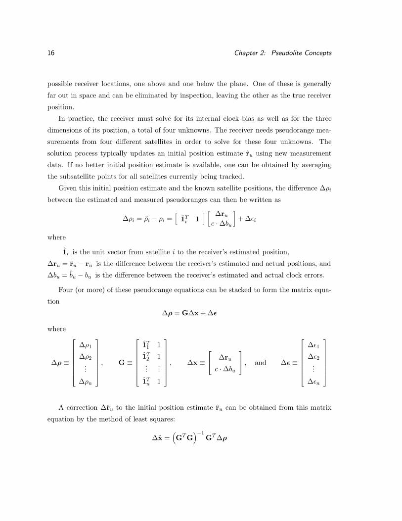
possible receiver locations, one above and one below the plane. One of these is generally
far out in space and can be eliminated by inspection, leaving the other as the true receiver
position.
In practice, the receiver must solve for its internal clock bias as well as for the three
dimensions of its position, a total of four unknowns. The receiver needs pseudorange mea-
surements from four different satellites in order to solve for these four unknowns. The
solution process typically updates an initial position estimate r̂u using new measurement
data. If no better initial position estimate is available, one can be obtained by averaging
the subsatellite points for all satellites currently being tracked.
Given this initial position estimate and the known satellite positions, the difference ∆ρi
between the estimated and measured pseudoranges can then be written as
∆ρi = ρ̂i − ρi =[
1̂Ti 1
] [∆ru
c ·∆bu]+∆εi
where
1̂i is the unit vector from satellite i to the receiver’s estimated position,
∆ru = r̂u − ru is the difference between the receiver’s estimated and actual positions, and
∆bu = b̂u − bu is the difference between the receiver’s estimated and actual clock errors.
Four (or more) of these pseudorange equations can be stacked to form the matrix equa-
tion
∆ρ = G∆x +∆ε
where
∆ρ ≡
∆ρ1
∆ρ2
...
∆ρn
, G ≡
1̂T1 1
1̂T2 1...
...
1̂Tn 1
, ∆x ≡
∆ru
c ·∆bu
, and ∆ε ≡
∆ε1∆ε2...
∆εn
A correction ∆r̂u to the initial position estimate r̂u can be obtained from this matrix
equation by the method of least squares:
∆x̂ =(GT G
)−1GT∆ρ

2.1: Code-phase GPS Navigation 17
The result ∆x̂ contains the position correction ∆r̂u as well as a correction ∆bu to the clock
bias estimate. The updated, accurate position r̂newu is then computed as
r̂newu = r̂u −∆r̂u
This process is repeated until the correction ∆x̂ is negligibly small.
When more than four pseudoranges are used in the navigation algorithm, a least-squares
residual ∆ρnew can be calculated from the final position and the measured pseudoranges.
When available, this residual is often used as a measure of the quality or accuracy of the
new position estimate, in a process known as Receiver Autonomous Integrity Monitoring
(RAIM) [2, Chapter 5].
Another quality measure, which is always available, is provided by the position covari-
ance matrix A =(GTG
)−1. The square root of the trace of A is known as the Geometric
Dilution of Precision (GDOP). GDOP describes the accuracy degradation of the position
solution due solely to the relative positions of the satellites. Various components of GDOP
describe the degradation in particular dimensions: Horizontal DOP (HDOP), Vertical DOP
(VDOP), Position DOP (PDOP), and Time DOP (TDOP). The GDOP concept assumes
that the errors in the individual pseudorange measurements are uncorrelated and have the
same statistics. This concept is explained further in [1, Chapter 11].
This abbreviated discussion of the unassisted GPS navigation algorithm is provided
as background for this chapter’s discussions of pseudolite-assisted navigation. For a more
detailed explanation, please refer to [1, Chapter 9], which this presentation closely follows.
The number of GPS satellites is limited, and their orbits are inconvenient for some
locations. Additional GPS signals can improve the availability and accuracy of unassisted
GPS navigation. It is difficult to provide these additional signals by launching additional
GPS satellites. If the area which must be served is small, it is far easier to add pseudolites.
2.1.3 Direct Ranging Pseudolite
The earliest pseudolite application, and perhaps the easiest to imagine, can be thought of
as a complete ground-based satellite. This pseudolite transmits code phase, carrier phase,
and data signals with the same timing as the satellite signals and with nearly the same
format. The receiver measures this signal to derive a code-phase pseudorange and uses it
in the standard GPS navigation algorithm. The only difference is that the position of the

18 Chapter 2: Pseudolite Concepts
pseudolite must be described in geographical terms rather than in the orbital elements used
by satellites.
The additional ranging signal provided by the pseudolite can be extremely useful, es-
pecially for the more demanding GPS applications such as aircraft approach and landing
[9]. Each additional pseudolite signal allows the user to perform basic navigation, fault de-
tection, and fault isolation using one less satellite signal than would otherwise be required.
This capability is valuable in areas where the normal satellite constellation does not pro-
vide sufficient availability, and even more valuable after one or more unexpected satellite
signal failures. Because satellites and pseudolites are entirely separate systems, presumably
controlled by separate organizations, the probability of a common failure mode is extremely
small.
Another benefit for aircraft applications is a significant improvement in vertical position
accuracy. The satellites are always above the horizon, as seen from an aircraft in flight, while
pseudolites are below the horizon. Therefore, adding a pseudolite to the navigation solution
will decrease the VDOP and increase the vertical position accuracy by a corresponding
amount. This improvement can be a factor of two or more, if the pseudolite location is
carefully chosen [9]. The vertical dimension of position accuracy is the most important for
aircraft, with the tightest specifications, so this improvement is especially significant.
The timing accuracy of pseudolite signals used for direct ranging must be comparable
to the accuracy of the satellite signals, to allow a GPS receiver to use the pseudolite simply
as an extra satellite in unmodified navigation algorithms. In practice, this means that the
pseudolite must contain a stable clock and some way to synchronize it to the GPS master
clock. A nearby receiver can perform this synchronization by computing the instantaneous
offset between the pseudolite’s clock and the clocks of the satellites in view. This instanta-
neous offset will be contaminated by the effects of SA and other errors. If the pseudolite’s
clock is sufficiently stable, these errors can be averaged out over time; if not, pseudoranges
measured from the pseudolite transmissions will contain errors comparable in magnitude to
SA.
To average out the errors in the instantaneous offset measurements, the pseudolite’s
clock must be stable within a few nanoseconds per day. As of this writing, this stability re-
quirement can only be met by atomic clocks costing thousands of dollars. If accuracy better
than SA is required, the direct-ranging pseudolite will be relatively expensive compared to
other pseudolite concepts which do not require precise clocks.

2.1: Code-phase GPS Navigation 19
GPS satellites
centralnavigationcomputer
mobile pseudolite
pseudolitepseudorange
vectors fixed receiver
fixed receiver
fixed receiver
fixed receiver
satellitepseudorange
vectors
Figure 2.2: Mobile Pseudolite
2.1.4 Mobile Pseudolite
Conventional GPS involves a single receiver processing signals from multiple satellite trans-
mitters. A converse system would involve multiple receivers processing signals from a single
transmitter to determine its location. Such a system has in fact been built for use on a
military test range [25].
The range is used to test navigation equipment, including GPS, under hostile conditions
such as severe jamming. On the other hand, the range controllers need to know the positions
of the test vehicles at all times, regardless of the jamming. These conflicting requirements
inspired range personnel to invent the mobile pseudolite concept (Figure 2.2).
Conventional GPS receivers, placed in fixed locations at the boundaries of the test area,
are shielded from the jammers so that they function normally. These receivers track GPS
satellite signals and simultaneously track signals from pseudolites placed on the test vehicles.
A central computer processes the received signals to generate instantaneous positions for

20 Chapter 2: Pseudolite Concepts
the test vehicles. The absolute timing of the mobile pseudolite signal is not important; only
the differences between the pseudoranges received at the fixed locations are used to navigate
a mobile pseudolite. Therefore, the mobile pseudolites do not require precise clocks.
2.2 Differential Code-phase GPS
The GPS signals measured by the user’s receiver contain a number of errors or deviations
from the mathematical ideal. The actual position of the GPS satellite is only known within a
few meters, and the timing of its clock may be off by a few nanoseconds (or up to 100 ns with
SA). The radio signal from the satellite is delayed as it travels through the ionosphere and
troposphere. Finally, the receiver can be fooled by signal reflections from nearby objects,
known as multipath. All these errors except multipath are spatially correlated; that is, the
sum of these errors will be similar for all receivers within a given area.
Differential code-phase GPS (DGPS) reduces spatially correlated errors in the GPS
satellite signals to negligible levels. A DGPS reference station, installed at a well-known
location, computes an assumed pseudorange for each satellite signal it detects. It then
measures the pseudorange for that satellite signal and subtracts the assumed pseudorange,
forming a “differential correction.” The DGPS reference station transmits these corrections
as digital data to nearby user receivers.
Each user receiver adds this correction to the pseudorange it measures for the same
satellite before performing the navigation algorithm described previously. Errors common
to both receivers, such as SA clock dithering, are entirely removed by this procedure. Other
errors, such as ionosphere and troposphere delays, are removed to the extent that they are
spatially correlated. Uncorrelated errors, such as multipath and receiver noise, add directly
to the user’s navigation error, but a high-quality DGPS reference receiver will minimize
them. DGPS concepts are described in [2, Chapter 1].
The digital correction message must be transmitted from the reference station to the
user receivers. One attractive way to do this is by pseudolite. Other possible datalinks are
discussed in [2, Chapter 1].
2.2.1 Digital Datalink Pseudolite
A pseudolite can transmit arbitrary digital data to GPS users, in the same way that the
satellites transmit their navigation data. This scheme has frequently been proposed for

2.3: Carrier-phase Differential GPS Navigation 21
transmission of differential GPS reference data [12, 31]. It is attractive because the user’s
navigation receiver already contains all the hardware necessary to tune and demodulate the
data signal; only a software upgrade is required.
If the traditional GPS signal format is used, the data rate for a single pseudolite signal
is only 50 bits per second. Simple modifications of this format could increase the data rate
up to a maximum of 1000 bps (for example, the proposed WAAS signal [31] uses 250 bps).
Higher data rates could be achieved with more complex modulation schemes, but these
would be incompatible with most existing receivers. An even higher overall ground-to-air
data rate could be achieved by modulating parallel data streams on several distinct Gold
codes simultaneously.
Data transmitted from the GPS satellites carries precise timing information both ex-
plicitly, in the data message, and implicitly, in the format and timing of the data bits
themselves. While receivers are equipped to measure this timing information, pseudolites
used solely for data transmission need not supply it. Such pseudolites can use inexpensive
clocks, only accurate to a few parts per million.
DGPS can remove most systematic errors from code-phase DGPS navigation, but the
accuracy of this mode remains limited by the precision of code-phase pseudorange meaure-
ments. For higher accuracy, the receiver must also measure the carrier phase of the satellite
signal.
2.3 Carrier-phase Differential GPS Navigation
Each C/A code chip is approximately 293 meters long; each cycle of the L1 carrier frequency
is about 19 cm long. These are the features of the GPS signal which receivers measure.
A good receiver can measure either feature with a precision of a fraction of one percent.
The precision in range is about 0.5 meters for C/A code phase and about 1 mm for carrier
phase. Despite this apparent superiority, real-time systems have rarely used carrier-phase
navigation because of the problem of ambiguity.

22 Chapter 2: Pseudolite Concepts
2.3.1 Carrier-phase Ambiguity
The C/A code is designed to be unambiguous; each chip has a distinct signature and cannot
be confused with its neighbors.1 Because of this, a receiver’s C/A code measurement gives
the pseudorange directly. This is not true for carrier phase measurements. Carrier cycles
are not unique; each cycle looks just like every other cycle. The receiver can measure the
fractional phase plus an arbitrary number of whole cycles, but cannot directly determine
the exact number of whole cycles in the pseudorange. This number, known as the integer
cycle ambiguity, must be determined by means other than direct measurement. Figure 2.3
illustrates these concepts.
As the fractional carrier phase passes through zero in the positive or negative direction,
the receiver can increment or decrement an integer counter as appropriate. The “relative
carrier phase” measurement consists of the instantaneous value of the integer counter plus
the fractional phase. This measurement is also known as “integrated doppler” or “carrier
beat phase” or “accumulated delta range” (ADR). The integer ambiguity is the difference
between this relative carrier phase measurement and the actual pseudorange at any given
instant. This integer ambiguity remains a constant for each signal as long as the receiver
maintains continuous tracking of that signal.
Although it is theoretically possible to navigate using carrier-phase pseudoranges to
the various satellites, carrier-phase navigation in practice is always done differentially. A
reference station at a known location makes relative carrier phase measurements for each
satellite in view, and broadcasts these measurements to nearby users. The user receiver
subtracts the reference station measurements from its own similar measurements, forming
a set of differential carrier-phase pseudorange measurements of the form
dρi = (ru − rd) · 1i +Ni + dεi
where
dρi is the differential carrier phase measurement for satellite i,
ru is the position of the user receiver,
rd is the position of the reference receiver,
1i is the unit vector from the user to satellite i,
Ni is the integer ambiguity associated with satellite i, and1The raw C/A code has an ambiguity at intervals of one epoch or approximately 300 km. This ambiguity
can be resolved by examining the data modulation.

2.3: Carrier-phase Differential GPS Navigation 23
Integer Ambiguity (whole number of carrier cycles)relativecarrierphase
Line-of-Sight vector(user to satellite)
reference receiver user receiver
arbitraryunknownpoint
Figure 2.3: Carrier-Phase Measurements and Integer Ambiguity
The receivers measure relative carrier phase precisely but cannot directlymeasure the exact number of whole carrier cycles between two points. Theinteger ambiguity must be determined by external means.
dεi is the sum of differential measurement errors associated with satellite i.
The integer ambiguities Ni cannot be measured from the instantaneous GPS signals
but must be determined by other means, some of which are described in the next section.
Once the ambiguities are known, the solution can be found using the algorithms of Section
2.1.2. This process is frequently called kinematic carrier phase navigation because it was
first developed in kinematic surveying applications.
The line-of-sight vector 1i appears as a constant in this equation, which can only be
true if the satellite signals have planar wavefronts. This is a useful approximation but is
not exact. The wavefronts are actually spheres with radii greater than 20,000 km. Ap-
proximating them as planes simplifies the navigation solution, as shown above, but leads to
systematic errors in the final position. These can be removed by adding to dρi a correction
based on the user’s position as measured by code-phase DGPS. Details on this and other
small corrections can be found in [29, Section 3.10]. These corrections will be assumed,
without comment, in the rest of this chapter.
24 Chapter 2: Pseudolite Concepts
2.3.2 Carrier phase Ambiguity Resolution
If pseudolites are not used, the strategies for resolving carrier phase integer ambiguities
fall into three broad classes: search methods, filtering methods, and geometrical methods.
(Practical algorithms frequently combine aspects of these three general methods.) All must
start with an estimate of the initial position or trajectory, generally derived from code-phase
measurements. The search and filtering methods also require an estimate of the error in
the initial position estimate.
Search methods use those estimates to generate a “search space” of all possible integer
combinations. If the error in the initial position is ±1 meter, there may be 10 possible
integers for each satellite and 10n possible combinations for n satellites in view. Positions
estimated using some of these combinations will be accompanied by large least-squares
residuals. If the residual is higher than some threshold, that combination is presumed to
be incorrect and is eliminated from further consideration. As time passes and the satellites
move, other combinations will yield high residuals and be eliminated. Eventually only one
combination of integers remains, which is presumed to be correct.
Filtering methods combine a series of n independent measurements of each satellite’s
code phase pseudorange to form a more accurate measurement. Statistically, the noise level
of combined, uncorrelated measurements should decrease as 1/√n. The goal is to reduce the
noise level to less than half the length of a carrier cycle, so that the carrier phase integers can
be determined directly. This goal is rarely met in practice. Code-phase multipath causes
correlation between sequential measurements, which violates the statistical assumption of
uncorrelated measurements. When used alone, filtering methods perform poorly.
Geometrical methods combine sets of simultaneous code phase and carrier phase mea-
surements in a single large matrix, then solve it to compute the position or trajectory
correction ∆r̂u and the integer ambiguities Ni at once. The condition number of the matrix
must be small enough to yield numerically accurate results. In physical terms, this means
that the individual sets of measurements must be separated in time so that the satellite
line-of-sight vectors are sufficiently different. (Measurements taken within a short period of
time do not contain enough “new information” to solve for the integer ambiguities as well as
the position.) The measurement sets must span many tens of minutes, due to the relatively

2.3: Carrier-phase Differential GPS Navigation 25
slow orbital motion of the satellites, before a useful solution can be computed. The solution
also gives DOP’s for both the position and integer estimates, which are excellent measures
of the quality of the solution.
The search and filtering methods depend on heuristic thresholds which must be adjusted
for good performance. Setting these thresholds involves a direct tradeoff between the time
taken to reach a solution and the probability of an erroneous solution. The probability
of error cannot be assessed in any particular case, but can only be measured statistically
for certain sets of conditions. These conditions include the actual performance of the GPS
satellite constellation. Thresholds set for good performance with a nominal constallation
may perform poorly if the constellation is degraded. These are serious concerns for a high-
integrity navigation application such as an aircraft landing system (Chapter 5).
Some receivers attempt to use information from the military’s encrypted signals on the
L1 frequency and on another frequency known as L2. Ambiguity solutions can be obtained
as much as ten times faster by properly combining measurements from both frequencies
in a technique known as wide-laning. Nevertheless, the time required to obtain a solution
with high confidence remains far longer than dynamic applications such as aircraft landing
navigation can tolerate.
2.3.3 Ambiguity Resolution using Pseudolites
Pseudolites can help a geometric algorithm in a moving receiver initialize the carrier-phase
ambiguities quickly and reliably. As the receiver moves past a pseudolite, the line-of-sight
vector from the pseudolite to the receiver sweeps across a large angle. An angular change of
60 to 90 degrees can be achieved in a few seconds. This change produces a well-conditioned
geometric matrix which can be solved for the integer ambiguities. DOP’s computed from
the matrix completely describe the accuracy of this particular solution. A universally valid
threshold can be applied to each DOP to guarantee a particular combination of accuracy
and integrity.
To illustrate a simplified example, Figure 2.4 shows a ship steaming past a pseudolite at
the entrance to a harbor. The ship is performing CDGPS navigation relative to the CDGPS
reference station in the background. The ship’s own receiver tracks signals from the GPS
satellites and a similar signal from the pseudolite. The reference station’s receiver tracks and
measures the same signals, and transmits time-tagged sets of simultaneous measurements
via the datalink to the ship.

26 Chapter 2: Pseudolite Concepts
GPS satellites
CDGPSreference
station
satellitepseudorange
vectors
CDGPS datalink
pseudolite signal "bubble"
satellitepseudorange
vectors
pseudolitepseudorangevector
user ship
pseudolite
ship's course
Figure 2.4: Pseudolite Initializes CDGPS Carrier-phase Ambiguities
As the ship moves past the pseudolite, it collects information which enables itto compute the CDGPS carrier-phase integer ambiguities.
The ship’s receiver subtracts these measurements from its own corresponding measure-
ments to form differential measurements. It computes an approximate position from the
differential code-phase measurements as described in Section 2.1.2. A set of successive
positions gives an approximate code-phase trajectory.
At the same time, the ship’s receiver computes a CDGPS trajectory nominally centered
on the code-phase trajectory. This CDGPS trajectory has the same shape as the actual
true trajectory (to the centimeter-level accuracy of CDGPS), but it is displaced slightly
from the true trajectory because the carrier-phase ambiguity integers are not yet known.
The ambiguity resolution process will determine the displacement vector, which is constant
because the ambiguity integers are constant.2
2The displacement vector actually changes slowly with satellite motion and other factors; this change isignored for the purposes of this simplified example.

2.3: Carrier-phase Differential GPS Navigation 27
As the ship passes the pseudolite, the direction and magnitude of the line-of-sight vector
from the pseudolite to the ship change dramatically. The ship’s receiver compares the
displaced CDGPS trajectory with the simultaneous differential carrier-phase measurements
of the range to the pseudolite. This comparison determines the location of the trajectory
relative to the known location of the pseudolite.
For example, if the ship moves through an arc of a circle centered on the pseudolite,
the differential carrier-phase measurement of the range to the pseudolite will be constant
(albeit a constant whose value is known only approximately). The CDGPS trajectory will
be an arc of a circle with a precisely known radius but an unknown center. Only one
trajectory—the arc previously described—is consistent with these two facts. The greater
the angle subtended by the arc, the more accurately the location of the pseudolite at its
center can be determined.
If the ship moves in a straight line past the pseudolite, the range to the pseudolite
will be a parabolic function of distance traveled. The center of the parabola indicates the
closest approach to the pseudolite, and the shape of the parabola indicates the distance
from the pseudolite to the line of motion. Again, the greater the change in the pseudolite’s
line-of-sight vector, the more accurately its location relative to the ship’s trajectory can be
determined. In practice, if the line-of-sight vector swings through more than 90 degrees,
this relative location will be determined to centimeter-level accuracy.
Assuming the pseudolite’s true location is accurately known, this process aligns the
measured CDGPS trajectory with the true trajectory. From this known trajectory, the
carrier-phase ambiguity integers can be determined. Once these integers are known, the
ship can navigate with centimeter-level accuracy anywhere within range of the CDGPS
reference station for any length of time, so long as it maintains phase lock on at least four
satellite signals. After the integer ambiguities are initialized, the pseudolite signal is no
longer needed.
The ship’s trajectory past the pseudolite need not be a circle or a straight line. These
are most easily visualized by humans, but any trajectory which provides sufficient change in
the pseudolite line-of-sight vector(s) can be analyzed by the mathematical algorithms used
in practice. These algorithms linearize the carrier-phase differential satellite and pseudolite
measurement equations about the code-phase differential trajectory, then use Gauss-Newton
iteration or forward/backward smoother techniques to solve for the CDGPS trajectory and
the carrier-phase integers simultaneously. The mathematics of this technique are presented

28 Chapter 2: Pseudolite Concepts
in [2, Chapter 15]. Detailed analysis of the performance of several solution algorithms can
be found in [30, Chapter 3].
The CDGPS navigation solution is initialized accurately only in the plane of the line-of-
sight vectors from the pseudolite to the user receiver. The vertical dimension of the ship’s
position is out of this plane, and thus poorly determined—but for a ship, that doesn’t mat-
ter. For an aircraft or other vehicle which requires accurate positions in three dimensions,
two or more pseudolites are necessary. Figure 5.1 is a diagram of the Integrity Beacon
Landing System (IBLS), which provides precise, reliable navigation data to aircraft on final
approach and landing. During its approach, an IBLS aircraft flies over a pair of pseudolites
to initialize its CDGPS navigation accurately in three dimensions. IBLS was extensively
tested during the research for this dissertation.
This technique of using pseudolites to initialize the carrier-phase integer ambiguities for
CDGPS navigation is quite general. Assuming the pseudolite signals are compatible with
the receivers used (a topic addressed in the following chapter), this technique can be used
with almost any vehicle which moves with respect to a nearby point. The vehicles can be
bulldozers grading a road, aircraft approaching a runway, or spacecraft performing orbital
rendezvous.
The apparent simplicity of this technique inspired the research which led to this disserta-
tion. The goal was to create a pseudolite which could easily be used in practice to initialize
CDGPS navigation. The initial result was the simple pseudolite described in Section 4.1.
Although the simple pseudolites themselves performed well, system-level difficulties with
this design came to light during the testing of IBLS (Section 5.2). These difficulties inspired
the creation of the synchrolite.
2.4 Synchrolites
Instead of synthesizing a precisely timed GPS-like signal from scratch, a pseudolite can
rebroadcast a coherent replica of a satellite signal. The pseudolite in this case functions
as a kind of electronic mirror, reflecting the satellite signal toward the user from a known
point on the ground (Figure 2.5). The user’s receiver can subtract the direct signal from the
reflected signal to compute a differential code- and carrier-phase pseudorange measurement.
The spatially correlated errors in the satellite signal are eliminated, just as in other forms
of local-area DGPS.

2.4: Synchrolites 29
synchrolite
GPS satellite
satellite signaldirect to user
GPSuser
satellite signal"reflected" by synchrolite
satellite signalto synchrolite
Figure 2.5: Synchrolite Reflects Satellite Signals Coherently
A synchrolite can be imagined as an “electronic mirror” which reflects GPSsignals from a known point on the ground. The user subtracts the direct signalfrom the reflected signal to obtain a differential GPS pseudorangemeasurement.
A pseudolite whose transmitted signal is synchronized to a received satellite signal has
come to be known as a “synchronized pseudolite” or synchrolite. Any synchrolite can be
used to initialize a CDGPS system, as Sections 5.2 and 5.3 demonstrate.
A synchrolite responds to changes in the received satellite signal within milliseconds;
this delay, known as latency, is determined by the bandwidths of the synchrolite receiver’s
tracking loops. By contrast, the latency of a typical DGPS reference station is much greater.
Such a station must measure the satellite signals, format a digital data message, and trans-
mit the message over a slow datalink; these functions can take a whole second or more to
accomplish. A synchrolite’s millisecond latency allows it to correct for the random SA clock
dither much more accurately.
If a synchrolite reflects at least four signals simultaneously, the user’s receiver can com-
pute a precise differential position from the synchrolite. This scheme provides continuous
differential reference data with millisecond latency while minimizing the major GPS error
sources.

30 Chapter 2: Pseudolite Concepts
parallelwavefronts
from satellite
rij = |rj – ri |
r ju = |ru –
r j|
1i . (ru–rj )
rij = |rj – ri |
range from satellite i to synchrolite j
range from synchrolite to user
range from satellite i to synchrolite j
excess range to user
unit vectorfrom satellite i
to user
1i
1junit vector fro
m
synchrolite j to user
user
synchrolite j
satellite i
Figure 2.6: Synchrolite Differential Pseudorange Measurement
2.4.1 Synchrolite Differential Measurements
A user receiver can simultaneously measure the pseudorange of a direct satellite signal and
the pseudorange of the same signal reflected from a synchrolite at a known point on the
ground. Subtracting these two measurements gives a differential pseudorange measurement
containing only those errors which are not spatially correlated: multipath, receiver noise,
and residual ionospheric and tropospheric error terms. The largest of these is multipath,
which contributes perhaps 1.4 meters of error (1σ); the other terms are negligible in com-
parison [2, page 26].
The synchrolite differential pseudorange measurement is derived as shown in Figure 2.6.
The GPS satellite is sufficiently distant that the wavefronts of its signals are assumed to be
parallel. The geometric range from satellite i through synchrolite j to the user is
riju = |rj − ri|+ |ru − rj |
where

2.4: Synchrolites 31
ri is the position of satellite i,
rj is the position of synchrolite j, and
ru is the position of the user receiver.
The geometric range from satellite i direct to the user can be written as
riu = |rj − ri|+ 1i · (ru − rj)
The second term in this equation is an excess range term which depends on the relative
locations of the satellite and the user as seen from the synchrolite.
The receiver measures pseudoranges corresponding to these geometric ranges. Code
phase pseudoranges are always available; carrier phase pseudoranges can be used instead for
higher accuracy if the integer ambiguities are known. The synchrolite navigation algorithm
in the receiver subtracts the direct pseudorange from the reflected pseudorange to obtain
the differential pseudorange
dρij = ρiju − ρiu
= |ru − rj | − 1i · (ru − rj) + c · tj + dεij
= 1j · (ru − rj)− 1i · (ru − rj) + c · tj + dεij
= (1j − 1i) · (ru − rj) + c · tj + dεij
where
dρij is the differential pseudorange measurement for satellite i through synchrolite j,
1i is the unit vector from satellite i to the user,
1j is the unit vector from synchrolite j to the user,
c is the speed of light,
tj is the signal’s travel time through synchrolite j, and
dεij is the sum of errors associated with this differential measurement.
The user clock bias bu is removed by the differencing operation because the user receiver
measures the direct and reflected signals at the same time. The synchrolite’s clock bias
is irrelevant because the signal is not processed but simply reflected. The only source of
timing uncertainty not already discussed is the travel time tj.

32 Chapter 2: Pseudolite Concepts
2.4.2 Synchrolite Reflection Delay
The synchrolite’s apparent internal time delay tj is the time required for a received signal
to travel through the cables, filters, and internal electronics of the synchrolite before being
retransmitted by the antenna. (This is different from the synchrolite’s latency, which is
the time required to respond to a change in the timing of the input signal.) For some
applications, tj is irrelevant. When a synchrolite is used to resolve CDGPS ambiguities,
for example, tj is computed as an integral part of the carrier-phase ambiguity adjustment
(which may no longer be an integer). For certain cases, such as a synchrolite which reflects
four or more signals, tj may be computed as part of the position fix as shown in Section
2.4.5.
In other circumstances, the exact value of the delay may be important. Details depend
on the particular implementation, but some characteristics of this delay can be predicted.
It will be approximately constant, with a value on the order of one microsecond. A one-
time factory calibration will determine the actual value within perhaps ten percent. The
remaining variability will be dominated by temperature and aging effects, so that a periodic
calibration in a thermal chamber might determine the value within one percent or less. A
synchrolite maintained at a constant temperature could have a virtually constant delay.
Information more specific than this must be measured after such synchrolites are designed.
The use of pre-calibrated delay values will be limited to applications which do not require
high accuracy or high integrity.
A synchrolite which reflects multiple signals can be designed so that the delays for all
signals are identical. (Identical delays will be assumed, without comment, in the remainder
of this dissertation.) A nearby monitor receiver at a known distance from the synchrolite
could determine the value of tj in real time, allowing the synchrolite to null out the delay,
or control it to a pre-specified value if desired. In fact, it is possible that the synchrolite
could monitor its own transmitted signal and adjust the delay without external hardware.
As previously mentioned, a synchrolite can be used to initialize carrier-phase ambiguities
in a CDGPS navigation system. The advantage of this idea is that the CDGPS reference
station need not monitor the synchrolite signal, as it must do with ordinary pseudolites. This
benefit may appear trivial in theory, but it is a great help in the planning and installation
of real-world systems. Sections 5.2 and 5.3 describe tests of synchrolites in this application.
Synchrolites can also be used as individual differential GPS reference stations. The
number of synchrolites required for full DGPS navigation depends on the number of signals

2.4: Synchrolites 33
number of synchrolitesnu
mbe
r of
sat
ellit
esea
ch s
ynch
rolit
e re
flect
s1 2 3 4
1
2
3
4
5
navigationimpossiblenavigationOK
Legend
navigation withRAIM and/or tj
5
2/7 = # of redundant RAIM measurementswith/without calculating tj for all synchrolites
X = calculation impossible+ = 10 or more
X/X
1/3
X/1 X/2
X/X 3/6 3/9 4/+
3/5 6/9 9/+ +/+
5/7 9/+ +/+ +/+
X/1 0/3 1/5 2/7
0/1
1/2
Figure 2.7: Synchrolite DGPS Navigation Possibilities
Very strong RAIM is available to a receiver which can measure signals fromseveral synchrolites.
each synchrolite can reflect, as Figure 2.7 shows. The user receiver must measure at least
three independent pseudoranges before navigation is possible. Additional pseudoranges al-
low the receiver to detect many navigation errors by monitoring the least-squares residuals
in a RAIM algorithm. Alternatively, the receiver can calculate the tj delays for one or more
synchrolites if necessary. The number of useful reflected signals is limited both by synch-
rolite capacity and by the number of signals the user receiver can measure simultaneously.
Receivers in synchrolite systems can make use of several times more correlator channels
than ordinary GPS receivers use.
The basic synchrolite DGPS navigation algorithm for synchrolites with known tj delays
is presented in the following section. Section 2.4.5 describes the modification to this basic
algorithm which allows the tj delays to be computed when enough signals are available.
2.4.3 Synchrolite Differential Navigation
As Figure 2.7 illustrates, many combinations of satellite and synchrolite signals can be
used for DGPS navigation. To develop the navigation algorithm, consider the case of three
synchrolites which each reflect the signal from a single satellite. Figure 2.8 illustrates this
case. The time delay tj through each synchrolite must be known in advance.
The algorithm for synchrolite DGPS navigation resembles that for conventional GPS
navigation. Assume that the signal from satellite i is reflected by m ≥ 3 synchrolites. The

34 Chapter 2: Pseudolite Concepts
singleGPS
satellite
synchrolite
synchrolite
synchrolite
one satellite signalreflected from
three synchrolites
signals directfrom satellite
Figure 2.8: DGPS Positioning with Several Synchrolites
A user can navigate with DGPS accuracy using three synchrolites which reflectonly one satellite signal.
user receiver observes a set of j differential pseudorange measurements (j = 1, 2, . . . ,m)
dρij = (1j − 1i) · (ru − rj) + c · tj + dεij
as described previously. If the carrier phase integer ambiguities are known, differential
carrier phase pseudorange measurements can be used to give greater accuracy.
Rearrange this equation to place the unknown terms on the right and the known (or
approximately known) terms on the left, giving
dρcij = dρij − c · tj + (1j − 1i) · rj = (1j − 1i) · ru + dεi
where dρcij is the corrected differential pseudorange from synchrolite j to the user, based on
signals from satellite i.
Obtain an initial user position estimate r̂u. Using the known synchrolite positions rj
and time delays tj, estimate the quantities 1̂j , 1̂i, and dρ̂cij . The difference ∆dρc
ij between
the estimated and measured pseudoranges can be written as
∆dρcij = dρ̂c
ij − dρcij =
[(1̂j − 1̂i
)T][∆ru] + ∆dεi

2.4: Synchrolites 35
Three or more of these range equations can be stacked to form the matrix equation
∆dρ = G∆ru +∆dε
where
∆dρ ≡
∆dρi1
∆dρi2
...
∆dρim
, G ≡
(1̂1 − 1̂i
)T
(1̂2 − 1̂i
)T
...(1̂m − 1̂i
)T
, and ∆dε ≡
∆dεi1∆dεi2
...
∆dεim
This matrix equation can be solved iteratively, just as in conventional GPS navigation,
to yield the actual position vector ru. One possible complication is that the line-of-sight
vectors 1̂j from the various synchrolites to the user may change significantly as the position
estimate r̂u is refined, because the user is relatively close to the synchrolites. These changes
may well impose a boundary on the initial position estimate, beyond which the navigation
algorithm will not converge. Further analysis or simulation is needed to determine the
magnitude and consequences of this effect.
Each row of this matrix equation corresponds to a single differential measurement, one
satellite signal reflected through one synchrolite. This equation can be extended by adding
a row for each available measurement. The total number of available measurements may be
constrained by the number of satellites or synchrolites in view, by the number of satellite
signals reflected by each synchrolite, or by the number of correlator channels in the receiver.
The number of receiver channels is the most likely constraint in a large synchrolite
system. Today’s generally available receivers have 12 channels at most. Any synchrolite
development effort should include the development of receivers with 48 or more channels,
so that all available signals can be processed.
2.4.4 Geometry of Synchrolite Navigation
The geometry matrix G derived above for synchrolite navigation serves the same role as the
G matrix in conventional GPS navigation, but its character is somewhat different. Each
row of the GPS G matrix is a unit vector; each row of the synchrolite G matrix is the
difference between two unit vectors. The magnitude of this difference vector varies from 2
to 0. This may appear surprising but is intuitively reasonable.

36 Chapter 2: Pseudolite Concepts
-90 -75 -60 -45 -30 -15 0 15 30 45 60 75 900
2
4
6
8
10
Elevation angle of user as seen from synchrolites (degrees)
DO
P (
nond
imen
sion
al)
VDOP
HDOP
PDOP
Figure 2.9: PDOP for Three Optimally Placed Synchrolites
This plot shows computed DOP’s for a user receiver centered on threesynchrolites optimally placed in an equilateral triangle, reflecting a satellitedirectly overhead at elevation 90 degrees. PDOP is less than 2 for userelevations from –36 degrees to +54 degrees above the plane of thesynchrolites. Minimum PDOP is 1.27 at +8 degrees elevation.
Consider the limiting cases in which the satellite, synchrolite, and user receiver are
collinear. If the synchrolite is between the satellite and the receiver, the reflected signal
will travel exactly as far as the direct signal. The measured differential pseudorange will
be zero at any distance from the synchrolite, so this particular measurement adds no new
information to the navigation solution. This is indicated by the geometry vector, which
equals zero for this case.
In the opposite case, the receiver is between the satellite and the synchrolite. Any
motion of the user receiver along this line will produce a change exactly twice as large in
the measured differential pseudorange. The magnitude of the geometry vector equals two for
this case, indicating that this measurement is twice as sensitive as a standard measurement.
Just as with conventional GPS, the geometric contribution to positioning errors can be
described by the DOP components of the covariance matrix A = (GT G)−1. It is instructive
to consider the variations in DOP with changing geometry.

2.4: Synchrolites 37
Consider the example from the previous section (Figure 2.8), in which three synchrolites
reflect a single satellite signal toward a user receiver. The optimal geometry for this case
(minimum DOP) occurs when the synchrolites form an equilateral triangle. The satellite
is directly over the center of the triangle, at an effectively infinite distance, and the user is
somewhere on the line which passes through these two points.
The DOP’s for this case are plotted in Figure 2.9 as a function of the user’s elevation
angle as viewed from any synchrolite.3 The shapes of the functions agree with intuition for
this case (although not with intuition for conventional GPS positioning).
At large elevations, the geometry approaches the collinear limiting cases discussed pre-
viously. VDOP degrades at large negative elevations, as the elements of the G matrix
approach zero, and improves toward a limit of about 0.29 at large positive elevations, as the
magnitudes of the matrix elements approach 2. HDOP is symmetrical about a minimum
at the zero-elevation point and degrades at high elevations where little cross-axis informa-
tion is available. PDOP is simply the RSS of VDOP and HDOP; it exhibits a very broad
minimum near +8 degrees elevation.
This example serves to illustrate the unusual DOP characteristics of synchrolite naviga-
tion. Further analysis is undoubtedly warranted as part of the design of any real synchrolite
system.
2.4.5 Synchrolite Navigation with Unknown Delays
Up to this point, the assumption has been made that the signal delays tj through each
synchrolite j are known from calibration or some form of external monitoring. This may
not always be true, or the calibration may not be sufficiently accurate. If each synchrolite
reflects two or more satellite signals, and if the total number of available signals is sufficiently
large, then the signal delays tj can be computed as part of the navigation algorithm. The
matrix in Figure 2.7 describes the conditions under which this is possible.
The algorithm used is an extension of the basic synchrolite differential navigation algo-
rithm described in Section 2.4.3. Assume that differential pseudorange measurements from
m synchrolites reflecting signals from n satellites are available, and that m and n meet the
conditions in Figure 2.7. In this case, j = 1, 2, . . . ,m and i = m + 1,m + 2, . . . ,m + n.3GDOP and TDOP are irrelevant for this case because only the position vector can be found from the
available data.

38 Chapter 2: Pseudolite Concepts
Write the corrected differential pseudorange as
dρcij = dρij + (1j − 1i) · rj = (1j − 1i) · ru + dεi + c · tj
In this case, tj remains on the right as one of the unknowns.
Obtain an initial position estimate r̂u and estimates of the delays t̂j. The t̂j estimates
can be based on prior calibration values or known characteristics of a particular synchrolite
family. Using these estimates and the known synchrolite positions rj, the difference ∆dρcij
between the estimated and measured pseudoranges can be written as
∆dρcij = dρ̂c
ij − dρcij =
[(1̂j − 1̂i
)T1] [
∆ru
c ·∆tj
]+∆dεi
Construct a state vector x from the unknown position ru and the unknown delays tj .
The set of individual pseudorange equations can then be stacked to form the matrix equation
∆dρ = G∆x +∆dε
The components of this equation involving a single synchrolite j are given by
∆dρ ≡
...
∆dρi1
∆dρi2
...
∆dρim
...
, ∆dε ≡
...
∆dεi1∆dεi2
...
∆dεim...
, G ≡
......
......
......(
1̂j − 1̂1
)T0 · · · 0 1 0 · · · 0(
1̂j − 1̂2
)T0 · · · 0 1 0 · · · 0
......
......
......(
1̂j − 1̂n
)T0 · · · 0 1 0 · · · 0
......
......
......
and
∆x ≡[∆ru ∆t1 · · · ∆tj−1 ∆tj ∆tj+1 · · · ∆tm
]T
The full matrix equation consists of one set of these components for each synchrolite, with
the partial column of 1’s in the G matrix moving to select the appropriate tj term.
This matrix equation can be solved iteratively as before. The results include updated
estimates of the position r̂u and the synchrolite time delays t̂j. The accuracy of these
updated estimates depends on the accuracy of the initial differential pseudorange measure-
ments and on the DOP’s calculated from the geometry matrix G. These DOP’s include
HDOP, VDOP, and one TDOP for each t̂j estimate.

2.4: Synchrolites 39
GPS satellites
synchrolite
directsatellitesignals
synchroliteuser
four reflected satellite signals
Figure 2.10: DGPS Navigation Using a Single Synchrolite
The synchrolite acts as a differential GPS reference station, transmittingsignals which correct for most of the errors in standard GPS navigation.
2.4.6 Operations with a Single Synchrolite
A single synchrolite which reflects four or more GPS satellite signals can be used as a
complete CDGPS reference station and simultaneously as a CDGPS initializer. This special
case of the generalized synchrolite navigation problem merits additional discussion because
it is the simplest synchrolite system to install. Figure 2.10 illustrates this case.
Three reflected signals are sufficient to establish the three dimensions of the user’s po-
sition relative to the synchrolite, if the time delay tj through the synchrolite is known. A
fourth signal can be used to compute the time delay tj as part of the navigation solution.
Additional reflected signals provide integrity information through the RAIM process. Ad-
ditional signals also enable navigation to continue uninterrupted despite occasional signal
losses due to satellite constellation changes or antenna masking.
For accurate CDGPS navigation, a pre-calibrated value of tj is unlikely to be adequate.
Instead, the actual value of tj must be computed by the navigation algorithm. A minimum
of four satellite signals must be reflected by the synchrolite in this case.
If the carrier-phase ambiguities are known, the same synchrolite navigation algorithm

40 Chapter 2: Pseudolite Concepts
can be used with carrier-phase pseudoranges to navigate near a synchrolite with centimeter-
level CDGPS accuracy. If the ambiguities are not yet known, the user vehicle can initialize
them by maneuvering near the synchrolite and applying the method of Section 2.3.3.
The obvious advantage of this concept is that CDGPS navigation with centimeter-level
accuracy requires only a single synchrolite and a single GPS receiver. No auxiliary datalinks,
antennas, or extraneous processors are required. The synchrolite can transmit data to the
users at a rate of 50 to 1000 bits per second per channel, but the user receivers do not
require any such data to navigate with CDGPS accuracy. Only the fixed location of the
synchrolite is required, which the receiver can look up in a local database.
Furthermore, the system-level description of the synchrolite is quite simple and clear: it
merely reflects satellite signals from a known point on the ground. All navigation processing
takes place inside the user’s receiver, under the control of a single design team with shared
assumptions. This minimal interface is a great advantage in the design and construction of
high-reliability navigation systems such as those required for aircraft.
2.4.7 Operations with a Single Satellite
Navigation using only one satellite signal is another special case of synchrolite navigation
which deserves mention for its possible utility. Conventional GPS navigation requires the
receiver to detect four satellite signals simultaneously. Even single-synchrolite DGPS navi-
gation requires at least three satellite signals. In locations with a restricted view of the sky,
such as a Manhattan boulevard, a narrow fjord, or an open-pit mine, it may be rare to see
more than one satellite signal at a time. Many applications could benefit from the accuracy
and convenience of DGPS navigation even in such locations.
Three or more synchrolites, strategically placed around the area of interest, enable any
user receiver which can detect a single satellite signal to perform CDGPS positioning. At
least three synchrolites visible to the user must reflect the signal from that satellite, and
the time delay tj of each synchrolite must be known in advance. Figure 2.8 illustrates this
concept.
Synchrolites intended for this mode of navigation must be sited carefully. For example,
consider a synchrolite installation in a mountain valley. Each satellite signal used for navi-
gation must be simultaneously visible to at least three synchrolites, and their signals must
be visible to all intended users in the valley. The mountain peaks are the obvious locations
for these synchrolites, but the actual locations must be chosen to prevent shadowing or

2.4: Synchrolites 41
severe multipath reflections by the bulk of the mountain. If each synchrolite signal can be
received by another, and if their locations are mutually known, then their time delays tjcan be continuously calibrated and broadcast to all users. Similar considerations apply to
synchrolites assisting other areas of restricted visibility.
The satellite signal reflected by the three synchrolites is used only as a source of rela-
tive timing; the absolute timing accuracy of this signal is irrelevant. In the unlikely event
of a total GPS constellation failure, the geosynchronous integrity channel (GIC) trans-
mitters aboard independent communications satellites could be used for navigation in this
mode. Even a separate mountaintop pseudolite could be used as the reference signal for
multiple-synchrolite navigation. Such a system could be entirely independent of the GPS
constallation and might be useful as a backup for applications such as aircraft navigation
in which the highest possible reliability is desired.
All the navigation algorithms discussed in this chapter share a family resemblance: it-
erated solution of a matrix equation involving a geometry matrix, a position vector, and a
vector of pseudoranges. It may be appropriate to use this shared structure to construct a
generalized navigation algorithm which can process data from any set of satellites, pseudo-
lites, and synchrolites. An “omnivorous” receiver incorporating such an algorithm would
provide the best possible availability and continuity of navigation in any situation.

42
�

Chapter 3
Practical Considerations
The designers of the GPS system assumed that all the transmitters would be aboard satel-
lites, at a large and relatively constant distance from all receivers. The signal levels at
the receivers would consequently be weak and relatively constant. This assumption drove
a number of tradeoffs in the design of the GPS system and its satellite transmitters, and
continues to influence receiver designs even today.
Pseudolites, of course, violate this assumption. Pseudolites are much closer than satel-
lites, and pseudolite signal levels at the receivers can be quite high. These strong pseudolite
signals will overwhelm the satellite signals and jam the receiver unless preventive measures
are taken. This is known as the “near/far problem.” It is the major constraint on pseudolite
system design, and this chapter examines it in detail.
Other constraints involve design details of existing receivers, mutual interference between
multiple pseudolites, and spectrum management issues. All of these are addressed in this
chapter.
The near/far problem is a systems problem caused by interactions between GPS satellite
signals and pseudolite signals inside the receiver hardware. To understand this problem, it
is first necessary to understand each of these elements individually. Existing GPS receivers
are optimized for existing GPS satellite signals, so those signals will be described first.
3.1 GPS Satellite Signals
Each GPS satellite broadcasts a “Clear/Acquisition” or C/A code signal which is available
for civilian use. The C/A code is a repeating, pseudorandom digital code chosen from
43

44 Chapter 3: Practical Considerations
a family of “Gold codes.” Gold codes, first described in [32], are sets of codes whose
auto-correlation and cross-correlation properties are well-defined. They are derived from
maximal-length linear feedback shift register (MLFSR) codes. Such codes are sequences of
2k − 1 bits, where k is the length of the shift register in bits. The individual bits of the
sequence are known as chips. An MLFSR sequence always contains the same number of 1
chips and 0 chips, plus exactly one more 1 chip; such sequences are said to be balanced.
Two properly chosen MLFSR codes can be added (modulo 2) to form a Gold code.
Shifting one of these MLFSR codes relative to the other by an integral number of bits
produces another Gold code of the same family. Each family of Gold codes contains the
two original MLFSR codes plus 2k − 1 of these combined codes, one for each of the possible
shifts. Of the combined Gold codes, 2(k−1) − 1 are balanced.
The GPS C/A codes are chosen from a family of Gold codes based on 10-bit MLFSR’s.
Each C/A code is 1023 chips long. There are 511 balanced codes, plus the two MLFSR
codes. The designers of GPS allocated 32 of these balanced codes to the satellites. Four
more codes were set aside for use by pseudolites. These particular 36 codes were chosen
because they could be generated by a minimum amount of digital logic, which was relatively
expensive at the time.
Each GPS satellite transmits one of the 32 assigned C/A codes. The C/A codes are
transmitted at a rate of 1.023 million chips per second, so that the code repeats exactly
1000 times per second. A navigation data message at 50 bits per second is transmitted by
adding each bit (modulo 2) to a group of 20 successive repetitions or epochs of the C/A
code. The GPS signal available to civilians consists of this signal (C/A code plus data)
modulated by binary phase shift keying (BPSK) on a microwave carrier frequency known
as L1. The L1 frequency is exactly 1540 times the C/A code chip rate, or 1575.42 MHz.
Many receivers exploit this relationship between the code and carrier rates to improve their
signal tracking accuracy.
In the frequency domain, the amplitude spectrum of a purely random 1.023 MHz bit
stream is a sinc(x) function(sinc(x) ≡ sin(πx)
πx
), a broad hump with nulls at multiples of the
1.023 MHz chip rate. A MLFSR sequence at the same chip rate is not entirely random, but
on a large scale it appears to have the same sinc(x) spectrum. Zoom in, and the spectrum
breaks up into individual spectral lines or “spikes” separated by the repetition rate of the
sequence. If the sequence repeats 1000 times per second, the spectral lines will be 1 kHz
apart. The tips of these spikes follow the outline of the sinc(x) function. The C/A code, a

3.1: GPS Satellite Signals 45
C/A code spectrum envelope
1.023 MHz
envelope
C/A code spectral lines
nulls
1 kHz line spacing
Figure 3.1: Spectrum of a C/A Code Signal
combination of two MLFSR sequences, has a similar appearance except that the tips of its
spectral lines vary by up to 7 dB above or below the sinc(x) envelope.1 The pattern of this
variation is different for each individual C/A code. Large-scale and small-scale views of a
typical C/A code signal spectrum are shown in Figure 3.1.
The data modulation at 50 bps broadens these spikes into little sinc(x) humps, each
100 Hz wide between the first nulls. This pattern appears only when the C/A code signal is
integrated over many data bits. Most GPS receivers integrate the signal over much shorter
periods, often only one or two C/A code epochs. (This integration time is also known as
the pre-detection interval.)
The bandwidth of the data modulation signal itself is 100 Hz, but the bandwidth of
the transmitted C/A code signal is 2.046 MHz, some 20,000 times wider. The name spread
spectrum has been given to signals which incorporate this sort of bandwidth inflation. The
power in a spread-spectrum signal is distributed across the entire transmitted bandwidth,
but it can be compressed back to the modulation bandwidth by auto-correlating the received
signal with a copy of the spreading code. The ratio of these two bandwidths, 43 dB in this
case, is known as the processing gain.1The spectral line at the center frequency is some 30 dB below the envelope; this is the only exception.

46 Chapter 3: Practical Considerations
3.1.1 C/A Code Correlation Properties
The auto-correlation properties of individual Gold codes are well-known, as are the cross-
correlation properties of two Gold codes from the same family. These deterministic prop-
erties are the reason that the C/A codes were selected from a family of Gold codes.
The auto-correlation function for the GPS C/A codes takes on only four values: 1,
65/1023, 63/1023, and 1/1023. Expressed in decibels, these are roughly 0 dB, −24 dB, and
−60 dB. The cross-correlation functions between two C/A code signals at the same fre-
quency are similar except that the 0 dB peak is missing. GPS receivers use these properties
to distinguish between signals from the different satellites. The satellites all transmit their
signals at the same time on the same frequency, and the receivers separate the signals by
their different codes.
The GPS satellites are constantly in motion. To receivers on the Earth’s surface, the
satellite signals appear to vary in frequency due to the Doppler effect. The maximum
frequency offset seen by a stationary receiver is approximately ±6 kHz. This complicates
the analysis of the cross-correlation properties of GPS C/A code signals. The analysis can
no longer be done simply by counting up matching bits, but must examine the frequency
spectra of the C/A codes.
As explained above, the spectrum of an individual satellite signal is a set of discrete
spikes roughly 100 Hz wide and spaced 1 kHz apart. All the energy the satellite transmits
is contained within those spikes. The cross-correlation between two signals can be thought
of as the “overlap” between two spectra. If the difference between the frequency offsets of
two satellite signals (as seen at the receiver) is an odd multiple of 500 Hz, their spikes will
not overlap and the cross-correlation will be essentially zero. Conversely, the worst-case
cross-correlation between two satellite signals will occur when the difference between their
frequency offsets is a multiple of 1 kHz, causing their spikes to overlap most closely.
The global worst-case cross-correlation expected between two C/A code signals can
be found by comparing each possible pair of C/A codes at each 1 kHz offset within the
expected range (±6 kHz). In practice, this must be done numerically. The worst-case
cross-correlation turns out to be −21.6 dB [1, page 105], a number which will reappear
frequently in this chapter.
This is truly a worst-case number, which applies only to a single, particularly unfortunate
combination of codes, frequency offsets, and time offsets. The typical cross-correlation
between two arbitrary satellite signals at a randomly chosen instant in time will be roughly

3.1: GPS Satellite Signals 47
−24 dB for 1/4 of the time and −60 dB for the rest. The overall time average can be taken
as −30 dB, the same result as for two random bit streams [1, page 106].
More details on the structure and correlation properties of GPS signals can be found in
[1, Chapter 3].
3.1.2 Signal and Noise Power Levels
Each GPS satellite broadcasts its L1 C/A code signal using about 15 Watts of power.
The signal travels over 20,000 km and spreads out to cover the entire Earth, weakening
considerably in the process. According to ICD–200 [7], an antenna on the Earth’s surface
with 0 dB gain will receive the L1 C/A code signal at a minimum power level of 160 dB
less than one Watt, or −160 dBW. This same power level can also be expressed as 130 dB
less than one milliwatt, or −130 dBm, in units more convenient for microwave work.
Whatever units are used, the L1 C/A signal power level is considerably below the power
level of ambient thermal noise, as shown below. The signal-to-noise ratio or S/N is therefore
negative. This is a consequence of a deliberate design decision. The GPS signal was designed
not to interfere with terrestrial microwave communication links which occupied the same
band when GPS was conceived. Although the S/N at the antenna is negative, de-spreading
the received spread-spectrum C/A code signal gives 43 dB of processing gain. This is
sufficient to ensure a positive S/N inside the receiver.
The power level of thermal noise at the antenna is given by N = kTB, where k is
Boltzmann’s constant, T is the ambient temperature (in Kelvin), and B is the measurement
bandwidth. Additional noise comes from the antenna preamplifier. A preamp is rated by
its noise figure, the ratio of its internally generated noise to the ambient thermal noise. The
calculations in this chapter assume a preamplifier noise figure (NF ) of 4 dB, although an
excellent preamp might have a noise figure lower than 2 dB.
For the traditional ambient temperature of 290K, the value of kT is −174 dBm/Hz. The
C/A code bandwidth works out to 63 dB-Hz. Adding these numbers, plus the 4 dB noise
figure, gives the precorrelation noise power in the receiver as −107 dBm. This compares to
the specified −130 dBm minimum signal power, giving a precorrelation S/N of −23 dB.
To “tune in” a C/A code signal from a particular GPS satellite, a receiver generates a
local copy of that C/A code and multiplies it with the mishmash of signals and noise coming
from the antenna. The output of this multiplier contains the auto-correlation product for
the desired C/A code and the cross-correlation products for any other C/A code signals.

48 Chapter 3: Practical Considerations
For this reason, the multiplier is known as a correlator. If the local copy of the C/A code
is synchronized with the received copy, the auto-correlation result will be a “1” (the 0 dB
auto-correlation peak) times the rest of the C/A code signal (the data modulation).
The correlator compresses the received signal power into a much smaller bandwidth,
without (ideally) compressing the noise power at all. If the signal is compressed all the way
down to the 100 Hz data modulation bandwidth, the new noise power level is kTB+NF =
−150 dBm. The signal power is still −130 dBm, so the postcorrelation S/N becomes
+20 dB. The difference between the postcorrelation and precorrelation S/N is the 43 dB
processing gain.
Many modern receivers report yet another number, C/N0, as a measure of signal
strength. This should not be confused with either of the S/N ratios mentioned above.
C/N0 is the ratio of the total signal power, −130 dBm as above, to the noise power in
a 1 Hz bandwidth (including the preamp noise figure). For the above example, N0 is
−170 dBm and C/N0 is 40 dB.
3.1.3 Code Division Multiple Access (CDMA)
Signals from the GPS satellites are all transmitted simultaneously on the same nominal
frequency. The output of a GPS receiver’s correlator contains the auto-correlation of the
desired C/A code signal and the cross-correlation of the C/A code signals from every other
visible satellite. These unwanted signals interfere with the receiver’s tracking of the desired
signal.
The signal-to-undesired ratio or S/U , analogous to S/N , can be calculated if the relative
power levels of all the signals are known. If all the satellite signals reach the antenna with the
minimum specified power level (−130 dBm), the worst-case S/U for any single interfering
signal will be 21.6 dB as determined above. The overall S/U will contain a typical 30 dB
contribution from each visible satellite except the desired one. In a realistic worst-case, 11
satellites will be visible and the overall S/U ratio will be 20 dB, exactly the same as the
S/N ratio. If a single one of these signals happens to hit the worst-case cross-correlation
peak, the S/U will momentarily decrease to 18 dB.
Both thermal noise and the remnants of undesired signals interfere with the receiver’s
ability to track the desired signal. They can be combined to form a signal-to-interference

3.2: Near/Far Problem 49
ratio, or S/I, which equals 17 dB for this typical example. Many GPS receivers can accu-
rately track a signal with a S/I of 6 dB, leaving some 11 dB of margin.2 By correlating with
the proper C/A code, the receiver can thus separate out the desired GPS satellite signal
from all the other signals being transmitted simultaneously on the same frequency. This
general technique is known as code-division multiple access or CDMA [33].
This analysis assumes that all the C/A code signals reached the receiver at the same
power level, which is rarely the case in practice. The received power level for any given
satellite can vary with its age, health, apparent elevation, and the gain pattern of the
receiver’s antenna. These effects combine to yield power levels up to 7 dB higher than the
specification [1, page 90].
The S/U contribution from a given undesired signal is directly proportional to its power
level. If all the satellite signals except the desired one were 7 dB higher than specified,
the receiver’s margin for tracking the desired signal would fall to 4 dB. The margin is
still positive, so one would expect the GPS system to remain functional even under these
conditions. This is truly a worst-case situation, as far as satellites are concerned. But it is
not the worst case imaginable.
The strength of a radio signal is an inverse square function of the range to the trans-
mitter; the signals grow weaker with distance. The range from a GPS satellite to a user
on Earth changes by about 20% at most, and the satellites’ antenna patterns are shaped
to compensate for this change [1, page 235]. Because of this, the strength of the signals
received from the GPS satellites remains relatively constant. This is not true for pseudolites.
3.2 Near/Far Problem
Consider the case of an airport pseudolite (APL) installed to assist aircraft on a landing
approach. Some proposed flight rules, modeled on existing rules for ILS approaches, require
that an aircraft must be tracking the APL signal before committing to the landing approach,
at a distance of 20 nautical miles (32 km) or more from the airport. At least one proposal
places an APL next to the runway, approximately where the ILS glideslope transmitters
are currently located. The aircraft may pass within 10 meters of such an APL as it lands.2Most analyses of receiver tracking loops quote only S/N ratios, neglecting interference other than thermal
noise. Noise is easier to model, but most of the interference in practice may come from undesired signals.Narrowing the tracking loop bandwidths makes a receiver more resistant to interference but reduces itsability to track sudden motions.

50 Chapter 3: Practical Considerations
nearboundarypseudolite
farboundary
near zone:pseudolite jamssatellite signals
pseudolite andsatellite signals
can both be tracked
far zone:pseudolite signalstoo weak to track
Figure 3.2: Zones of the Near/Far Problem
The ratio of these “far” and “near” ranges is about 3200:1. If the pseudolite transmits
a constant power level, the signal level received by the aircraft changes with the inverse
square of the range between them. In this example, the aircraft sees the pseudolite signal
level change by some 70 dB. At closest approach, the aircraft will be attempting to track
simultaneously the satellite signals at −130 dBm and the pseudolite signal at −60 dBm.
Recall the worst-case cross-correlation margin of 21.6 dB. If the pseudolite simply trans-
mits a continuous C/A code signal, it will exceed this margin by nearly 50 dB at closest
approach. The aircraft’s receiver is virtually guaranteed to lose track of the satellite sig-
nals and to start tracking spurious pseudolite cross-correlation peaks instead. In practice,
the pseudolite signals will begin to jam the satellite signals as the range to the pseudolites
decreases. This well-known effect is usually called the near/far problem.
Figure 3.2 shows this problem schematically. The “far boundary” is the range at which
the pseudolite signal is too weak to be tracked. The “near boundary” is the range at which
the strong pseudolite signal begins to interfere with the satellite signals. To navigate with
signals from both satellite and pseudolite signals, the receiver must remain in the zone
between these boundaries, where both sets of signals can be tracked.
The far boundary can be defined as the surface on which the pseudolite signal power
is equivalent to the minimum specified satellite signal power of −130 dBm. The distance
from the pseudolite to the far boundary is determined by the power level which the pseu-
dolite transmits. By contrast, the ratio of the distances to the far and near boundaries is
determined, not by an absolute power level, but by the receiver’s tracking margin based on

3.3: Existing GPS Receivers 51
cross-correlation interference from the pseudolite.
Section 3.1.1 showed that a single interfering C/A code signal causes S/U interference
at a level of −21.6 dB maximum relative to a desired C/A code signal when both are at
the same power. If the power level of the interfering signal increases, the S/U interference
will increase by the same amount, eventually dominating all other S/I components in the
receiver. If the receiver requires a minimum S/I of 6 dB for C/A code tracking, then the
interfering signal can grow 15.6 dB stronger before disrupting the desired signal. For a
single pseudolite which transmits continuous C/A code signals, this 15.6 dB margin sets
the near/far range ratio at about 6:1.
This 6:1 range ratio is an estimate based on a chain of realistic but imprecise assump-
tions. It provides a starting point for discussion, but actual measurements of the tracking
margin for a given receiver installation should be incorporated into real system designs.
Section 3.4 describes systems such as IBLS in which this simplistic 6:1 ratio might be
useful and some conventional techniques which might improve the ratio slightly. Subsequent
sections describe methods which can markedly improve this ratio. Some of these methods,
although feasible in theory, will fail in practice due to non-ideal characteristics of most
current GPS receivers. The following section discusses this receiver problem.
3.3 Existing GPS Receivers
As previously shown, the GPS satellite signals are considerably weaker than thermal noise
by the time they reach the Earth. Most existing GPS receivers are optimized for this weak-
signal condition. Strong pseudolite signals can cause problems for these receivers quite
apart from the cross-correlation effect.
Conventional radio practice defines a quantity known as dynamic range as the ratio of the
power levels of the strongest and weakest signals that the receiver can demodulate without
either excessive noise or excessive distortion.3 A receiver’s dynamic range is determined
by the design of its radio frequency (RF) and intermediate frequency (IF) circuits and, in
particular, by the effectiveness of its automatic gain control (AGC) circuit. The dynamic
range of an ordinary radio receiver is usually quite high. For example, digital cellular phones
which follow the European GSM standard must accept signals as weak as −104 dBm and as3Several slightly different definitions of receiver dynamic range exist; cf. [34, page 64] and [35, page
15.18]. These small differences are irrelevant to this discussion.
52 Chapter 3: Practical Considerations
strong as −13 dBm, which requires a minimum dynamic range of 91 dB. This is far greater
than the dynamic range of a typical modern GPS receiver.
Designers of GPS receivers generally have assumed that only continuous GPS satellite
signals will be present in the GPS band, and that these signals will always have a negative
S/N ratio. These are the conditions envisioned and specified in ICD–200 [7]. Under these
conditions, a large dynamic range is not necessary. Furthermore, the useful dynamic range
of a receiver which sees only continuous C/A code signals is limited to 21.6 dB in the worst
case (and perhaps 30 dB in the best case) by the cross-correlation interference described
above.
To these designers, it did not appear cost-effective to add a larger dynamic range to
the receiver electronics than cross-correlation interference would permit. Moreover, the
assumption that S/N is always negative permits enormous simplifications of the receiver
design, with corresponding reductions in cost. Virtually all non-military GPS receivers
currently available use this sort of simplified design.
If the S/N ratio is always negative, the precorrelation RF and IF electronics see only
thermal noise. The noise level is affected only by temperature and minor variations in
individual electronic components. Some receivers can track the absolute noise level over a
narrow range (≤ 20 dB); the rest simply assume the noise level is constant.
Virtually all modern GPS receivers use a digital correlator, which requires the analog
IF signal to be converted to a digital signal for processing. This step must be performed by
an analog-to-digital (A/D) converter circuit. A fast A/D converter with small quantization
errors is an expensive piece of precision electronics. Designers reduce the cost of modern
receivers by using simple A/D converters with a small number of bits and correspondingly
large quantization errors.
If the dominant component of the A/D converter’s input is thermal noise, the converter’s
quantization errors are dithered, drastically reducing their effect. This effect is so profound
that many receivers have been designed with a single-bit A/D converter, a simple compara-
tor. The theoretical performance of a one-bit correlator is only about 2 dB worse than the
theoretical best for a perfectly linear correlator, if (and only if) noise dominates the input
band [36, page 552]. The receiver’s dynamic range in this case is bounded by the minimum
detectable signal level (perhaps S/N ≈ −30 dB) and by the assumption that S/N < 0.
Most other receivers use A/D converters with two or three bits. Again, thermal noise
is assumed to dominate the A/D input, and the thresholds for the extra bits are set at

3.3: Existing GPS Receivers 53
certain points (for example, the 2σ point) in the Gaussian noise distribution. Automatic
gain control (AGC) is used to maintain these thresholds at the desired levels with respect
to the receiver input.
The assumption that noise dominates the GPS band is frequently invalid. Military
receivers have always faced the threat of jamming (strong in-band signals designed to disrupt
navigation). All receivers can be affected by leakage from satellite phones, whose assigned
frequencies start 35 MHz above the GPS band. Finally, signals from nearby pseudolites
could be far stronger than the noise level in the GPS band.
Most inexpensive consumer GPS receivers use single-bit A/D converters. These re-
ceivers, which depend on thermal noise to dither their A/D quantization errors, simply
cease to function in the presence of continuous in-band signals stronger than the noise level.
This situation is equivalent to hard-limiting a group of CDMA signals, a practice which has
been known for decades to fail [37, 38].
Narrowband signals will jam a single-bit receiver completely if the signal power is 6 dB
higher than the noise power [37, Figure 2]. Noise-like signals such as C/A code (or amplified
thermal noise) will effectively reduce the postcorrelation S/N by the amount that they
exceed the thermal noise level. It was previously shown (Section 3.1.3) that the tracking
margin in a typical receiver is about 10 dB. The more noise-like an interfering signal is, the
closer it can approach 10 dB above the thermal noise level before the receiver loses track of
the satellite signals.
Multi-bit receivers exhibit similar behavior due to the action of the AGC. The AGC
continually changes the receiver gain to maintain the thresholds at particular levels relative
to the incoming signal. This is typically done by sensing what fraction of time each threshold
is exceeded, and adjusting the gain to keep these fractions at specified values.
If an interfering signal exceeds the thermal noise level, the AGC will react by reducing the
overall receiver gain. This reduces the power of the interfering signal, but it simultaneously
reduces the power of the already weak GPS satellite signals. If the satellite signals levels
decrease by more than about 10 dB, the postcorrelation S/N will fall below the level needed
to track these signals and the receiver will lose lock. The actual level of interference required
to jam the receiver depends on the detailed characteristics of the AGC system and the
interfering signal. In some cases, a multi-bit receiver may tolerate interference levels a few
dB higher than single-bit receivers. The mechanism of jamming is different from the single-
bit case, but the eventual result is the same. Continuous pseudolite signals 10 to 20 dB

54 Chapter 3: Practical Considerations
stronger than the thermal noise level will prevent most modern GPS receivers from tracking
satellite signals, causing a loss of navigation capability.
One way to avoid this problem is to transmit pseudolite signals in short bursts or
pulses. This concept is examined further in Section 3.6. Another approach is to improve the
dynamic range of the GPS receiver. The APL example mentioned previously would require a
receiver with at least 70 dB of dynamic range. Achieving this with a straightforward receiver
design requires 12 bits of resolution. A suitable 12-bit A/D converter costs approximately
$20 as of this writing, compared to $1 or less for a one-bit converter. A chip containing two
12-bit correlators might rival the complexity of today’s 12-channel, 2-bit correlator chips,
which also cost approximately $20. Obviously, a GPS receiver with 70 dB of dynamic range
would be considerably more expensive than existing receivers.
Most civilian GPS receivers have limited dynamic range; for economic reasons, this will
probably remain true for the foreseeable future. Pseudolites which transmit continuously
will jam these receivers whenever they enter the near radius of the pseudolite. If the
near radius covers an area accessible to the general public, the public is likely to protest.
Pseudolites will not be widely accepted unless they present minimal interference to current
and future GPS receivers with limited dynamic range. Of the possible solutions to the
near/far problem presented in Section 3.5, only pulsing appears to meet this constraint
while still allowing long-range transmissions in the L1 band.
3.4 Near/Far Tolerance
Section 3.2 showed that a pseudolite which transmits a continuous C/A code signal has
a theoretical near/far range ratio of 6:1 based on cross-correlation interference and the
tracking margin of a typical receiver. Conservative engineers will add safety factors to
such theoretical numbers when designing systems for general use. With safety factors,
such a system might be required to function with a near/far ratio of only 3:1. This could
be a crippling constraint for systems which require continuous pseudolite coverage. If a
pseudolite is used only to initialize CDGPS navigation, however, continuous coverage is not
required. Such systems can function well despite severe near/far constraints.

3.4: Near/Far Tolerance 55
pseudolite
α
pseudolite signal "bubble"
IBLS user aircraft trajectory
near far
bubbleentry
bubbleexit
Figure 3.3: Side View of IBLS Flight Path over Pseudolite
3.4.1 Trajectory Constraints
The Integrity Beacon Landing System (IBLS, described further in Chapter 5) is typical of
CDGPS navigation systems initialized by pseudolites. IBLS uses the changing geometry
as an aircraft flies over a set of pseudolites to compute and initialize carrier phase integer
ambiguities. Once these integers are known, they can be tracked until the satellite signals
are lost; the pseudolite signals are no longer needed.
A typical aircraft trajectory past an Integrity Beacon pseudolite, shown in Figure 3.3,
traces a chord through the hemispherical “bubble” within which the pseudolite signal is
strong enough to be measured. As this chord is moved closer to the pseudolite itself, the
central angle (shown as α) increases toward 180 degrees and the required near/far range ratio
increases without limit. The near/far range ratio for any angle α is given by r = sec(α/2),
which becomes infinite for α = 180 degrees.
The accuracy of the IBLS position determination for a single flyby depends, among
other things, on the magnitude of the central angle. It has been found in practice that
flight paths which produce an angle α = 90 degrees result in accurate determinations of
the carrier phase integer ambiguities; no further advantage is gained by increasing α. This
value of α = 90 degrees corresponds to a near/far range ratio of√2 = 1.414. The 3:1 safety
limit corresponds to α ∼= 140 degrees. Clearly, any aircraft trajectory which provides an
α between 90 and 140 degrees is acceptable. The success of the IBLS flight tests shows
that this constraint is easily met in this application. (Most IBLS tests also used separate
antennas for satellites and pseudolites, as discussed in Section 3.4.3.)

56 Chapter 3: Practical Considerations
Other systems can be designed in which the “near” region is simply inaccessible. For
example, a pseudolite used by ground vehicles might be installed on a tower or pylon at a
height greater than the near radius. Systems with limited mobility, such as the simulated
space experiments discussed in Chapter 6, might be incapable of penetrating the near
boundaries of their pseudolites. While trajectory constraints are not a general solution to
the near/far problem, they form an important class of specialized solutions.
3.4.2 Antenna Patterns
Conventional radio techniques can help to ease the near/far constraint. If the user receivers
follow predictable trajectories, it may be possible to shape the gain patterns of the transmit
and receive antennas to deliver a weaker signal in the direction(s) of closest approach.
Figure 3.4 shows this concept. For acheivable antennas and highly predictable trajectories,
it is reasonable to expect a 12 dB reduction in antenna gain from the far boundary to
closest approach, corresponding to a factor of 4 increase in the near/far range ratio. System
designers must keep in mind that user receivers which do not follow the nominal trajectory
can be jammed near closest approach, losing all navigation capability. Antennas with
distorted gain patterns have similarly distorted phase patterns, which must be calibrated
before use in CDGPS systems.
3.4.3 Separate Antennas
It is possible to construct a user receiver with separate antenna inputs for satellite and
pseudolite signals. The gain patterns of the separate antennas can be optimized to minimize
leakage of the pseudolite signals into the satellite channel. For example, British researchers
found that signals transmitted by a ground-based pseudolite to an antenna mounted atop
an airliner were attenuated by 10 to 20 dB [39]. The near/far range ratio improves as a
direct function of the signal separation (unless limited by crosstalk between channels inside
the receiver).
Virtually all of Stanford’s IBLS flight experiments have used receivers with multiple
antenna inputs, fed by antennas mounted along the top and bottom of the aircraft fuse-
lage. Such receivers are presently rare, but could easily be produced in quantity if demand
warranted.

3.4: Near/Far Tolerance 57
pseudolite
pseudoliteantennagain pattern
-3 dBic gain
+3 dBic gain
-3 dBic gain+3 dBic gain
user antennagain pattern
Figure 3.4: Improving Near/Far Ratio with Antenna Patterns
Antenna gains are minimized at closest approach and maximized at the farboundary, improving the near/far power ratio by 12 dB.
Military researchers have developed an anti-jamming technique known as a Controlled
Reception Pattern Antenna (CRPA), in which signals from two or more antennas are adap-
tively combined to produce a null (minimum response) in the direction of a jammer. This
technique could be adapted to reduce interference from a single pseudolite, although ex-
tending it to multiple pseudolites is more difficult.
The ultimate extrapolation of this concept is a receiver with a separate, highly direc-
tional antenna focused on each signal source. This ideal can be approximated by an exten-
sion of the phased-array antenna concept. Signals from an array of separate omnidirectional
antennas can be combined to produce a narrow composite beam, which can be steered by
adjusting the signal phases in the combiner. In theory, each channel of a GPS receiver could
have its own combiner fed by signals from a common antenna array, giving each channel
the equivalent of a directional antenna aimed at its particular satellite or pseudolite.
If the signals are correlated and then combined, the combining operation can easily
be performed in software. For n channels and m antennas, this approach requires n ×m correlators, but correlators are becoming quite inexpensive. This multi-beam antenna
concept was first proposed by Clark Cohen at Stanford University [40], where Eric Olsen

58 Chapter 3: Practical Considerations
and others are currently investigating it.
3.5 Near/Far Solutions
The 6:1 near/far range ratio discussed above derives from the 21.6 dB cross-correlation
margin between the satellite signals and an assumed pseudolite signal format (continuous
C/A code transmissions). To solve the near/far problem, it is necessary to find a new
pseudolite signal format which provides a much higher cross-correlation margin against the
existing satellite signals. The satellite signals cannot easily be changed, but pseudolite
signal formats can be chosen arbitrarily to optimize system performance.
Over the past dozen years or so, the GPS community has devoted considerable effort
to the design and analysis of new pseudolite signal formats. This section decribes several
techniques which can be applied to pseudolite signals, singly or in combination, to improve
the correlator dynamic range. Most of these techniques are explained in more detail in the
literature; two are presented here for the first time. Receiver modifications will be required
to detect signals transmitted using most of these techniques. These modifications are well
within the state of the art and will not be described.
3.5.1 Out-of-Band Transmissions
A pseudolite can be built to transmit its signal at any useful frequency in the radio spec-
trum. If the transmission frequency is sufficiently different from the GPS L1 frequency, the
pseudolite’s signal will be attenuated by the GPS receiver’s filters, preventing interference
with the satellite signals. The obvious disadvantage of this approach is that a separate
radio frequency (RF) tuner is then required to receive the pseudolite signals. Adding a
second RF significantly increases the cost and complexity of a GPS receiver. Furthermore,
the timing of pseudolite signals received through the second RF can drift with time and
temperature relative to the GPS signals in the primary RF. This complicates pseudolite
navigation algorithms.
Notwithstanding these problems, this approach has been successfully tested at least once
[23]. It has the additional advantage that regulatory permission for pseudolite transmissions
may be easier to obtain outside the sensitive GPS bands (see Section 3.12). Because the
implementation of such pseudolites is relatively straightforward, this dissertation will not
consider them further.

3.5: Near/Far Solutions 59
1.023 MHz
Figure 3.5: Pseudolite Signal with Frequency Offset
A C/A code pseudolite signal (black) centered on a null of the satellite signals(grey) nevertheless causes interference.
3.5.2 Frequency Offset
The satellite C/A codes are transmitted using binary phase shift keying (BPSK) modulation.
Such signals occupy a broad spectrum, but there are holes, or nulls, at certain frequencies
where no energy is transmitted. These nulls occur on each side of the carrier, at multiples of
the bit transmission rate or chip rate (1.023 MHz for C/A code). The matching demodulator
inside a GPS receiver follows a similar pattern, responding to energy in the BPSK spectral
pattern and ignoring any signals in the nulls.
Elrod and van Dierendonck [17] suggested that a pseudolite signal be transmitted on
a carrier frequency centered on one of the C/A code nulls, as shown in Figure 3.5. Their
thought was that the pseudolite signal, in the null of the satellite signals, would be discarded
by the receiver, reducing or eliminating the near/far problem.
If the pseudolite signal were a narrow-band signal with little modulation, this would in
fact occur. Unfortunately, a C/A code pseudolite signal has the same broad shape as a
satellite signal. As Figure 3.5 shows, there is considerable overlap between the two signals,
and the overlap causes interference. McGraw’s analysis [19] shows that the worst-case S/U
cross-correlation between a particular pair of C/A codes decreases by only 3.6 dB when one
code is offset by 1.023 MHz into the other’s null. At this frequency offset, the codes are
shifting relative to each other at 660 chips per second, so the duration of this worst-case
peak will be very brief. It then becomes appropriate to consider the average S/U cross-
correlation interference. For the same two codes, McGraw shows that the average S/U
decreases by 8 dB with the 1.023 MHz frequency offset. This decrease is useful but is not,
in itself, a complete solution to the near/far problem.
Few current GPS receivers can track a signal offset by 1 MHz from L1. With that fact
in mind, van Dierendonck has also proposed [13] a frequency offset of 30 kHz or more,

60 Chapter 3: Practical Considerations
larger than any realistic Doppler shift but small enough that most current receivers could
track the offset signal without modifications. A pseudolite signal offset by 30 kHz shifts
by 19 chips per second relative to a satellite signal exactly on L1. This shift bounds the
duration of a worst-case cross-correlation peak. In addition, any significant frequency offset
reduces the chance that a receiver will “jump” from tracking a satellite signal to tracking
a cross-correlation peak from the pseudolite. Apart from these two relatively minor effects,
the small frequency offset scheme offers no clear advantages.
As noted above, the C/A code signal consists of a set of narrow spikes 100 Hz wide,
spaced 1 kHz apart. It would seem possible to transmit a pseudolite signal at a small
frequency offset, such that the spikes from the pseudolite signals did not overlap the satellite
signals. Unfortunately, the frequency offsets of the satellites themselves are constantly
changing due to Doppler shift. Even if it were possible to track and avoid the signals of all
the visible satellites, the pseudolite would often need to jump from a frequency “window”
that was closing because of satellite motion to another “window” that was opening. All
receivers tracking the pseudolite signal would lose lock during each of these jumps. In
critical applications such as aircraft landing, this loss of continuity could not be tolerated.
3.5.3 Frequency Hopping
In general, the frequency offset schemes of the previous section fail because the pseudolite
transmits a wideband C/A code signal. A pseudolite which instead transmits a narrow-
band signal centered on a null of the C/A code will generate much less interference with
the satellite signals. The narrow-band signal can alternate or hop between the lower and
higher nulls so that the time-averaged frequency matches that of a satellite signal, making
this scheme suitable for synchrolites. Multiple pseudolite signals can be transmitted simul-
taneously with different hopping patterns. To the author’s knowledge, this scheme has not
previously been proposed in the GPS literature.
Figure 3.6 shows an example of a pseudolite signal which is hopped between the upper
and lower C/A code nulls, spending half of the C/A code epoch (500 microseconds) at each
frequency. A preliminary simulation gives the cross-correlation between this signal and a
representative C/A code signal at 6 kHz frequency offset (the maximum expected Doppler
shift) as −44 dB. For a receiver which requires 6 dB S/U , this corresponds to a near/far
range ratio of 80:1. The cross-correlation improves (decreases) for smaller frequency offsets.
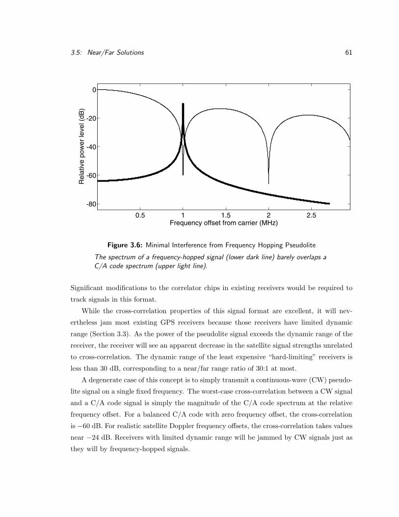
3.5: Near/Far Solutions 61
0.5 1 1.5 2 2.5
-80
-60
-40
-20
0
Frequency offset from carrier (MHz)
Rel
ativ
e po
wer
leve
l (dB
)
Figure 3.6: Minimal Interference from Frequency Hopping Pseudolite
The spectrum of a frequency-hopped signal (lower dark line) barely overlaps aC/A code spectrum (upper light line).
Significant modifications to the correlator chips in existing receivers would be required to
track signals in this format.
While the cross-correlation properties of this signal format are excellent, it will nev-
ertheless jam most existing GPS receivers because those receivers have limited dynamic
range (Section 3.3). As the power of the pseudolite signal exceeds the dynamic range of the
receiver, the receiver will see an apparent decrease in the satellite signal strengths unrelated
to cross-correlation. The dynamic range of the least expensive “hard-limiting” receivers is
less than 30 dB, corresponding to a near/far range ratio of 30:1 at most.
A degenerate case of this concept is to simply transmit a continuous-wave (CW) pseudo-
lite signal on a single fixed frequency. The worst-case cross-correlation between a CW signal
and a C/A code signal is simply the magnitude of the C/A code spectrum at the relative
frequency offset. For a balanced C/A code with zero frequency offset, the cross-correlation
is −60 dB. For realistic satellite Doppler frequency offsets, the cross-correlation takes values
near −24 dB. Receivers with limited dynamic range will be jammed by CW signals just as
they will by frequency-hopped signals.

62 Chapter 3: Practical Considerations
The problem of receiver dynamic range can be minimized by spreading a pseudolite’s
transmitted energy over a broad region of the frequency spectrum. An infinite variety of
spreading codes can be used to accomplish this. Of these, the standard ICD–200 C/A codes
are the most obvious choice, but other codes may also be useful.
3.5.4 New Spreading Codes
Receiver manufacturers would no doubt prefer that pseudolites transmit their signals using
the standard ICD–200 C/A codes, because the correlators for these codes already exist in
all GPS receivers. On the other hand, non-standard spreading codes can improve the cross-
correlation properties of the pseudolite signal and the overall dynamic range of the system.
Section 3.7 describes a few such codes, with estimates of the performance improvements
and the extra work required in receiver design.
3.5.5 Pulsed Transmissions
Acting on a suggestion from Brad Parkinson, the RTCM-104 committee proposed that
pseudolite signals be transmitted in frequent, short, strong pulses [12]. The pulses would
be strong enough to be easily tracked, despite having a duty cycle of only 10% or so. The
interval between pulses, with the pseudolite transmitter turned off, would allow receivers
to track the satellite signals without interference.
This scheme has been tested in practice several times, and many modifications have been
proposed. Both the synchrolite and the AIB described in the following chapters successfully
used pulsed transmissions. Pulsing is not a panacea, but it is a very important concept in
pseudolite design. Section 3.6 discusses in detail this concept, its implications, and its
limitations.
3.6 Pulsed Pseudolite Signals
A pseudolite can only interfere with GPS satellite signals while it is transmitting. If the
pseudolite transmits only 10% of the time, it interferes only 10% of the time. During
the other 90% of the time, the receiver hears only the satellite signals. Most existing
receivers will be able to track the satellite and pseudolite signals simultaneously under
these conditions. This section describes the fundamentals of this technique and several
possible optimizations.

3.6: Pulsed Pseudolite Signals 63
The signal from a pseudolite will generally be strong enough to exceed the dynamic
range of the receiver (Section 3.3). In this case, the receiver is said to saturate at a given
power level. Signals stronger than the saturation level will be reduced to that level before
being presented to the correlators. When the receiver is saturated by a strong signal, weaker
signals and noise will simply vanish from the correlator’s output. This phenomenon might
appear undesirable, but the pulsing technique uses it to advantage.
For a concrete example, consider a receiver with a single-bit digitizer tracking signals
at the typical power levels discussed in Section 3.1.2. The satellite signals at −130 dBm
are 23 dB weaker than the level of thermal noise, which dithers the quantization errors of
the one-bit digitizer. This dithering can only occur for signals weaker than the noise level,
which effectively sets the saturation level equal to the noise level.
A signal from a distant pseudolite pulsed with a 10% duty cycle once per C/A code epoch
(100 µs on, 900 µs off) might arrive at the receiver with a peak power level of −120 dBm.
This signal will not saturate the receiver. Virtually all receivers integrate C/A code signals
over at least one epoch (1 ms). The average signal power received from the pseudolite
over one epoch is identical to the nominal satellite power level (−130 dBm). Ideally, this
pseudolite signal should be indistinguishable from a satellite signal with the same average
power. Deviations from this ideal are discussed later in this section.
As the receiver approaches the pseudolite, the peak pulse power level increases. Eventu-
ally it will increase above the receiver’s saturation level, which is equal to the thermal noise
level at −107 dBm. After that point, the peak power level seen by the receiver’s correlators
will remain constant, no matter how closely the receiver approaches the pseudolite. This
saturation effect can be thought of as bounding the near/far problem to a manageable range
ratio.
The effect of pulse saturation on both the pseudolite and satellite signals must be exam-
ined. For the pseudolite signal, the effect is quite simple. During the pulse, the pseudolite
signal is received at the saturation power level (−107 dBm) with essentially infinite S/N .
When the pulse is off, the pseudolite signal correlator sees only thermal noise at the same
saturation power level. Averaging over one pulse period yields an average precorrelation
S/N of −9.5 dB, some 13 dB higher than the S/N of the example satellite signals. Ideally,
the receiver should be able to track the saturated pseudolite signal quite well.
The pulsed pseudolite signal affects both the signal power and the interference level
seen by the satellite tracking channels. During the pulse, the receiver is saturated and the

64 Chapter 3: Practical Considerations
satellite signals are completely blocked. This causes a 10% (0.5 dB) reduction in the average
satellite signal power. The pseudolite signal also generates cross-correlation interference in
the satellite channels, with a worst-case power of 21.6 dB below the saturation level during
the pulse. Averaging this peak interference level over the entire C/A code epoch gives the
actual interference level of
−107 dBm− 21.6 dB− 9.5 dB = −138.1 dBm
A receiver which requires a S/I of 6 dB to accurately track a signal will have 1.6 dB of
margin when tracking a −130 dBm satellite signal through the worst-case interference from
this pseudolite. Because the margin is always positive, the receiver should never lose lock
on the satellite signals regardless of its distance from the pseudolite. Thus, this pulsed
transmission scheme appears to solve the near/far problem. In practice, pulsing is a useful
tool but not a panacea.
3.6.1 Pulse Blanking
Pulsed pseudolite interference to satellite signals can be reduced by implementing pulse
blanking in the receiver. The idea is to disable the satellite correlators during the pseudolite
pulse. If the correlators are not running, then the pulse cannot cause interference. The
blanking signal can be derived from a saturation detector in the receiver’s RF circuits,
or from a clock if the pseudolite’s pulse timing is predictable. Inverse blanking of the
pseudolite correlators, so that they run only during the pulse, will eliminate the noise which
accumulates between pulses and boost the average pseudolite S/N to near infinity.
3.6.2 Receiver Saturation Characteristics
If blanking is not implemented in the receiver, the pulsed pseudolite concept depends on
the assumption that the receiver will saturate during the pulse. The concept of saturation
is that a receiver limits all incoming signals to a certain maximum level. This is a useful
model but is not always an accurate description of actual receiver hardware. Saturation is
inherently an “overload” mode of operation, outside of normal conditions. Few receivers
are actually specified for operation in this mode, and some may perform poorly. In general,
the time required to recover from saturation is proportional to the degree of overload above
some threshold. In the limit, excessive power levels will cause permanent physical damage
to any receiver.

3.6: Pulsed Pseudolite Signals 65
Single-bit receivers without AGC follow the saturation model most closely. A single
signal at any power from the thermal noise level (−107 dBm) up to perhaps −20 dBm4
will dominate the correlator inputs with a virtually infinite S/N . Receivers should recover
from signals in this range in less than a microsecond (one C/A code chip). If two or more
signals are present in this range simultaneously, the strongest will dominate provided that
it is more than 10 dB more powerful than the next strongest signal. Two simultaneous
signals at the same power level will interfere with each other, and neither will be received.
Multi-bit receivers are more problematic. Such receivers use a “sign” bit, which cor-
responds to the single bit of simpler receivers, and one or more “magnitude” bits. The
input to the quantizer is usually assumed to be Gaussian thermal noise, and the thresholds
for the magnitude bits are set at various thresholds such as the 1σ and 2σ points in the
Gaussian distribution. The actual analog values corresponding to these points vary with
time, temperature, and environment, so multi-bit receivers generally include some form of
Automatic Gain Control (AGC) to keep the thresholds set correctly.
For our purposes, AGC systems can be classified in three categories: “fast,” “slow.” and
“very slow,” depending on their reaction time compared to the pulse width (Figure 3.7).
• A fast (or “wideband”) AGC system will react almost instantaneously to an incoming
pulse, so that the thresholds are correct during most of the pulse. When the pulse
ends, it will again react quickly, setting the thresholds correctly for the satellite signals
buried in thermal noise. This type of AGC functions well under pulsed interference.
• A slow AGC will begin to react during the pulse, but will not finish resetting the
thresholds by the time the pulse ends. It will then react equally slowly, so that the
thresholds are set too high for proper satellite tracking for a long time after the pulse.
• A very slow AGC reacts to the signal power averaged over a period greater than the
length of the pulse pattern (for example, a whole C/A code epoch). In this case, the
thresholds will be set to a constant level which is too high by a factor related to the
pulse duty cycle.
Both types of slow AGC systems end up setting the thresholds too high for proper
satellite tracking in the presence of pulsed pseudolite signals. This will not affect pseu-
dolite tracking, but the satellite signals will appear weaker than they would without the4This upper limit is determined by the onset of intermodulation distortion in the receiver’s RF signal
path, which is highly dependent on implementation details.
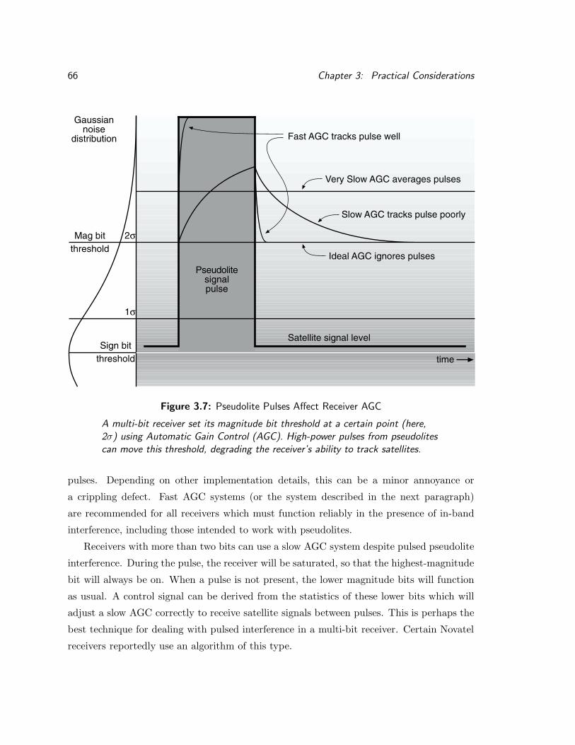
66 Chapter 3: Practical Considerations
Mag bitthreshold
Ideal AGC ignores pulses
Fast AGC tracks pulse well
Gaussiannoise
distribution
Sign bitthreshold
1σ
2σ
Pseudolitesignalpulse
Slow AGC tracks pulse poorly
Very Slow AGC averages pulses
time
Satellite signal level
Figure 3.7: Pseudolite Pulses Affect Receiver AGC
A multi-bit receiver set its magnitude bit threshold at a certain point (here,2σ) using Automatic Gain Control (AGC). High-power pulses from pseudolitescan move this threshold, degrading the receiver’s ability to track satellites.
pulses. Depending on other implementation details, this can be a minor annoyance or
a crippling defect. Fast AGC systems (or the system described in the next paragraph)
are recommended for all receivers which must function reliably in the presence of in-band
interference, including those intended to work with pseudolites.
Receivers with more than two bits can use a slow AGC system despite pulsed pseudolite
interference. During the pulse, the receiver will be saturated, so that the highest-magnitude
bit will always be on. When a pulse is not present, the lower magnitude bits will function
as usual. A control signal can be derived from the statistics of these lower bits which will
adjust a slow AGC correctly to receive satellite signals between pulses. This is perhaps the
best technique for dealing with pulsed interference in a multi-bit receiver. Certain Novatel
receivers reportedly use an algorithm of this type.

3.6: Pulsed Pseudolite Signals 67
3.6.3 Pulse Duty Cycles
The amount of interference produced by any pulsed pseudolite is directly proportional to
the fraction of time it is transmitting, known as the duty cycle. Low duty cycles, which
minimize interference to surrounding receivers, are obviously preferred. The tradeoff is that
pseudolites with lower duty cycles provide weaker signals which are harder to track.
A 10% duty cycle, as recommended by the RTCM-104 committee [12], has been used
in the examples so far. Unfortunately, two such pseudolites in close proximity will together
blank out 20% of the GPS satellite signals, which is as much interference as most receivers
can tolerate. Multiple nearby pulsed pseudolites can only be useful if their duty cycles are
reduced. It is natural to ask what the minimum possible pseudolite duty cycle might be.
The answer to this question depends largely on the design details of the receivers used.
A complete analysis is impossible here, but the factors involved will be described. The pulse
repetition rate is assumed to be at least as high as the rate at which the receiver samples
the outputs of its correlators, so that subsampling effects can be ignored.
It is a standard result that carrier phase tracking accuracy is a function of the S/N
ratio of the carrier signal and the bandwidth of the tracking loop. For the case of a pulsed
pseudolite signal which saturates the receiver, the S/N ratio is nearly infinite, but the
S/I ratio is not. The dominant source of interference is inaccuracy in the code phase
tracking, which transforms signal samples into interference at inaccurately placed chip edges.
(Receiver signal samples taken during a slightly misaligned chip transition will be given the
wrong signs by the correlator, transforming them into interference.) Nevertheless, carrier
tracking accuracy should be quite high for a saturated pseudolite signal.
Code phase tracking presents a slightly different problem. The information required
to track code phase appears only at the edges of the code chips. (A code sequence, or
pulse, with a constant sign cannot be tracked.) Conceptually, tracking performance is
proportional to the number of chip edges per pulse. This number is determined by the
product of the pulse width, the chip rate, and a factor (roughly 0.5) which describes the
average number of “bit flips” per chip in the sequence. The minimum number of edges
per second required for continuous tracking of the code phase depends on the tracking loop
bandwidth, the S/N or S/I ratio after the receiver quantizer, the maximum allowable error,
and an efficiency factor which describes how well a given receiver uses each edge. Note that
the maximum allowable code phase tracking error in CDGPS systems is much higher than

68 Chapter 3: Practical Considerations
in DGPS systems; a receiver can probably track carrier phase accurately even with code
phase errors greater than one-tenth of a chip.
Because this analysis is difficult, it is appropriate to cite experimental results here. C/A
code pseudolites with duty cycles as low as 5% have been tracked by Stanford researchers
using relatively standard multi-bit receivers, and duty cycles of 7% are in common use.
Single-bit receivers seem to require pseudolite duty cycles of 10% to 12% for reliable tracking.
Duty cycles as low as 1% have been proposed for P-code pseudolites. This corresponds
to approximately the same number of chip edges per second as a C/A code pseudolite with
a 10% duty cycle. Clearly, lower pseudolite duty cycles require higher chip rates.
Any given receiver can only tolerate a certain amount of pulse interference (total pulse
duty cycle) before it begins to lose track of the satellite signals. It is natural to ask what
this level might be. The answer depends on the details of the receiver implementation, but
a simple analysis for a single-bit receiver can be given here.
Section 3.2 showed that the precorrelation S/N for a satellite signal at the minimum
specified power of −130 dBm is −23 dB. The postcorrelation S/I is 17 dB in a typical
receiver without pulse interference. This typical receiver requires S/I ≥ 6 dB to maintain
lock on a satellite signal.
Pseudolite pulses will saturate a single-bit receiver at the noise level. The ratio of
saturated pseudolite signal power to satellite signal power during the pulse will be the
inverse of the S/N ratio or +23 dB. In a receiver without blanking, this pseudolite power
will cross-correlate in the satellite tracking channels, causing interference. The interference
power will be 21.6 dB (worst-case) or 24 dB (typical) less than the saturated power. The
typical ratio of pulse interference power P to existing interference power I is then
P/I = 17 dB + 23 dB− 24 dB = 16 dB
During the pulse, a blanking receiver will see the satellite signal vanish but will not accept
interference from the pseudolite signal. A non-blanking receiver will see this interference at
a P/I ratio of 16 dB. This pulse interference adds to the existing interference. The resulting
S/Iavg ratio, averaged over the entire pulse period, is given by
S/Iavg = 10 log[
s(1− d)pd+ (1− d)
]
where
d is the pulse duty cycle (0 ≤ d ≤ 1),

3.6: Pulsed Pseudolite Signals 69
20
17
10
6
0post
-cor
rela
tion
S/I
or S
/N pulsed pseudolite signals
pulse duty cycle0% 10% 20% 30% 40% 50% 60%
with blanking
without blanking
satellite signals:
need 6 dB to track
Figure 3.8: Pseudolite Pulse Duty Cycle Tradeoff
The duty cycle of a pseudolite pulse determines how well it can be tracked andhow much it interferes with the satellite signals.
s = 10(S/I)/10 is a linear measure of S/I, and
p = 10(P/I)/10 is a linear measure of P/I.
This equation is plotted as the “without blanking” curve in Figure 3.8. For a typical
receiver which requires 6 dB of S/I to maintain satellite tracking, the maximum acceptable
total pulse duty cycle is approximately 20%. This figure also shows the effectiveness of pulse
blanking in reducing cross-correlation interference. To illustrate the tradeoff, the estimated
S/I for a single pulsed pseudolite signal is plotted on the same scale. This estimate is based
on historical experience during pulsed pseudolite experiments at Stanford.
3.6.4 Pulse Patterns
A pseudolite’s duty cycle is the average fraction of the time during which the pseudolite is
actually transmitting. A chosen duty cycle can be achieved in many different ways. The
most obvious is to simply transmit a fixed pulse width at fixed intervals; for example, 100 µs
on, 900 µs off.
Such simple patterns cause problems for many receivers. The Fourier transform of the
pulse pattern just described shows strong spectral lines at 1 kHz intervals. In effect, the
pulsing process mixes the spectrum of the pseudolite’s transmitted signal with the spectrum
of the pulse pattern, replicating the signal at 1 kHz intervals above and below its center
frequency.

70 Chapter 3: Practical Considerations
These replicated or aliased signals are all weaker than the main signal. If the pseudolite
signal saturates the receiver, however, many of the aliases will be strong enough to be
detected and tracked. Most receivers will accept an aliased signal as valid and stop searching
for the real signal. In practice, it is rare to acquire the real signal rather than an alias when
simple pulse patterns are used. The use of code-phase aiding (Section 3.10.1) can ameliorate
this problem, but the best solution is for the pseudolite to transmit pulse patterns which do
not generate strong aliases. Such patterns appear random or pseudorandom to the human
eye.
This discussion so far applies to all pulsed pseudolites. The remainder of this section
specifically addresses the important special case of pulsed C/A code pseudolites, which have
been the focus of recent research at Stanford.
The pseudorandom pulse pattern best known in the pseudolite commnuity is the one
defined by the RTCM-104 committee a decade ago [12]. This pattern defines 11 possible
“slots” in a C/A code epoch, each 93 chips or about 91 µs long. A pulse is transmitted in
one of these slots during each epoch, in a fixed sequence which repeats every 200 epochs.
This pattern was designed to transmit 50 bps data in a mode compatible with “fast
multiplexing” GPS receivers, which were common at the time. These receivers are now
obsolete, but the anti-aliasing properties of the RTCM pattern are still useful.
Most pulsed pseudolite experiments at Stanford have used the RTCM pulse pattern
with receivers which integrate signals over a single C/A code epoch. For this case, it is
important to synchronize the pulse pattern with the C/A code epoch of the pseudolite’s
transmitted signal. If this is not done, the receiver will see many epochs which contain
two pulses and many others which contain no pulses. Receivers have trouble tracking
signals under these conditions. It has been empirically noted that receivers have trouble
tracking unsynchronized simple pulse patterns as well, although the mechanism in this case
is unknown.
Although the pulse patterns discussed so far transmit exactly one pulse per C/A code
epoch, this is not a hard constraint. Both faster and slower rates can be useful.
A pulse pattern which includes five regularly spaced pulses per C/A code will produce
aliased signals separated by 5 kHz. This separation is wide enough that most receivers will
acquire the main signal, rather than one of the aliases, without assistance. To maintain a
given duty cycle, the duration of each pulse would be reduced to one-fifth of the former

3.6: Pulsed Pseudolite Signals 71
value. A pseudorandom pulse pattern with five pulses per epoch would virtually eliminate
aliasing as a concern.
On the other hand, closely spaced pulses cause difficulties in siting multiple pulsed
pseudolites as part of a system. The following section discusses these difficulties in more
detail. One solution is to expand the interval between pulses from any one pseudolite.
The pulse interval can be expanded by transmitting only one pulse for every few C/A
epochs. User receivers must integrate incoming signals over at least the same number of
epochs to ensure that pulse energy is always detected. To maintain a given duty cycle,
the individual pulses must themselves be expanded. The allowable expansion is limited by
interference to receivers which are not part of the system. Many such receivers integrate
over a single C/A code epoch and will fail if more than about 20% of any given epoch is
blocked by pseudolite pulses.
3.6.5 Mutual Interference
While individual pseudolites can be useful, many conceptual systems include a set of several
pulsed pseudolites operating simultaneously. Unless such systems are carefully designed, the
pulsed signals from different pseudolites will interfere with each other and with the GPS
satellite signals.
The total pulse duty cycle at any given location, including pulses from all pseudolites
visible at that location, must be kept below about 20%. This must be true both as a long-
term average and during any given C/A code epoch. Otherwise, receivers at that location
are likely to lose track of the GPS satellite signals.
Pseudolite pulses are assumed to saturate the receiver; this is the rationale for pulsing.
Saturation causes any receiver to act like a single-bit, hard-limiting receiver. In saturation,
only one signal at a time can be received cleanly, and only if it is significantly (10 dB or
more) stronger than any other signals simultaneously present [37, 38]. Simultaneous signals
of roughly equal strength will interfere with each other in a saturated receiver, so that
neither signal is received.
If the thresholds are set correctly, it is theoretically possible than an unsaturated multi-
bit receiver could receive multiple pseudolite signals simultaneously. Blanking of the satellite
correlators would be necessary to prevent cross-correlation interference from the unsaturated
pulses. In theory, such a receiver could track one pseudolite for each bit of its digitizer. The
bit thresholds must be dynamically adjusted to follow the instantaneous signal strengths of

72 Chapter 3: Practical Considerations
the various pulses, and the complexity of this scheme makes its implementation unlikely.
However, the same result could be achieved in a receiver with many bits of dynamic range,
as described at the end of Section 3.3.
The total duty cycle limit sets an upper bound on the number of pseudolites which can
be visible from any location. The simultaneous interference effect constrains the relative lo-
cations of those pseudolites. While an exhaustive analysis of possible pseudolite placements
is impossible, some general principles may be observed.
The total duty cycle constraint is severe. Empirical data from research at Stanford
indicate that a minimum duty cycle of 7% is required for reliable tracking of C/A code
pseudolites. Only two or perhaps three such pseudolites can be allowed to saturate any
given receiver, or the receiver will be unable to track satellite signals reliably.
The trend to date has been to propose pseudolites with transmission ranges measured
in tens of kilometers. Very few such pseudolites can be permitted in any given area. For
example, it might be possible to install one pseudolite at each of the three airports in the
San Francisco Bay area, but no other pseudolites would be allowed anywhere nearby.
This trend should be reversed. Pseudolite transmissions should be viewed as a form of
pollution and minimized accordingly. Any proposed pseudolite system should be scrutinized
for ways to reduce the required range and transmit power of the pseudolites. The smaller the
radius of saturation, the more pseudolites can be allowed. Meanwhile, researchers should
focus on minimizing the duty cycle required for each pseudolite, using faster codes, blanking,
and whatever other techniques are needed.
The RTCM-104 report recommended a minimum pseudolite spacing of 54 km [12] to
prevent mutual interference. By contrast, IBLS (Section 5.1) requires an aircraft to fly over
a pair of pseudolites during an approach to landing. These pseudolites can be no more than
a few hundred meters apart. This dilemma was resolved by synchronizing the pseudolites’
pulses appropriately.
A simple, repetitive pulse pattern with a 10% duty cycle consists of a pulse followed by
“dead time” equal to nine pulse widths. Such simple patterns are generally undesireable, as
described previously. However, it is possible to construct a pseudorandom pulse pattern in
which every pulse is followed by a “dead time” equal to several pulse widths. (The minimum
dead time in the RTCM-104 pulse pattern [12] is one pulse width,)
Two or more pseudolites located a small distance apart can be synchronized so that

3.7: New Spreading (PRN) Codes for Pseudolites 73
each transmits in the other’s dead time.5 The distance between pseudolites must be small
compared to the pulse width times the speed of light, so that the pulses do not overlap
when viewed from any direction. Of course, the total duty cycle constraint still applies.
3.7 New Spreading (PRN) Codes for Pseudolites
In general, the goal of a spreading code is to make the resulting spread-spectrum signal
resemble band-limited thermal noise as closely as possible. Shannon’s information theorems
imply that the most noise-like signals are the most efficient. Accordingly, one might search
for pseudolite spreading codes which resemble noise more closely than the BPSK C/A codes,
whose spectra have a definite structure. The most noise-like signals are those least affected
by the receiver dynamic range constraints described in Section 3.3.
For the particular case of GPS pseudolites, another important goal is to minimize the
cross-correlation between the chosen spreading code and the existing satellite C/A codes.
Such codes do not provide “flat” spectra; instead, they concentrate energy in areas of the
spectrum where the C/A code energy is minimized. An extreme example is the frequency-
hopping signal described previously. This approach is fundamentally limited by Doppler
frequency offsets in the satellite signals.
The tradeoff between these two goals requires a detailed knowledge of the target re-
ceiver’s implementation. Such tradeoffs will not be made here; this dissertation simply
offers a variety of possible spreading codes for future research.
Another goal, operational rather than mathematical, is to expand the universe of avail-
able spreading codes as far as possible. If each pseudolite can be assigned its own unique code
at the factory, the administrative overhead of coordinating codes among various geograph-
ical locations can be avoided. This could be quite convenient if the number of pseudolites
grows large.
The options for a non-standard spreading code include changing the code bit pattern, the
transmission rate, and the modulation method. These options are not mutually exclusive
but may be combined to good effect.
Some of the codes described here are considerably more complex than C/A code, and
thus more difficult to acquire as stand-alone signals. Pseudolites will rarely be used in a5A similar approach was suggested by van Dierendonck [13], using pulse patterns which are more prone
to aliasing.

74 Chapter 3: Practical Considerations
stand-alone manner, however, and a technique known as “code phase aiding” can be used
to speed acquisition of pseudolite signals in a CDGPS system. Section 3.10 describes this
technique.
3.7.1 Additional C/A Codes
The C/A code generator defined in ICD–200 can produce a total of 1023 separate Gold
codes, plus the two base MLFSR codes. Of these, 512 are not balanced. Unbalanced
codes are harder to modulate in a pseudolite and may be more vulnerable to narrow-band
interference. Most receiver implementations cannot track the individual MLFSR codes.
ICD–200 reserves 36 of the remaining 511 balanced codes for use by GPS satellites. Of
the remaining 475 useful C/A codes, the 10 with the best cross-correlation properties were
chosen for the Wide Area Augmentation System (WAAS) broadcasts from geostationary
satellites. This leaves 465 codes, whose properties are only slightly worse, which could be
used by pseudolites. This number is large enough that, with proper coordination, no two
pseudolites simultaneously visible to a user receiver will share the same code. It is not large
enough for every individual pseudolite to have its own distinct code.
3.7.2 Multi-Epoch C/A Codes
Awele Ndili of Stanford University has proposed a code sequence which consists of a stan-
dard C/A code followed by an inverted replica of the same code [24]. In a receiver whose
integration time is a multiple of 2 ms (two C/A code epochs), this sequence will present zero
cross-correlation interference to another C/A code signal if the frequency offset between the
two signals is zero. For a frequency offset of 500 Hz, however, the cross-correlation will be
only about 3 dB less than the cross-correlation between the two unmodified codes.
Ndili’s process can be viewed as a simple means of increasing the length of a C/A code.
This process is generally compatible with existing receivers, but the benefits are limited. It
can be extended to any desired length usingWalsh functions [41, page 421]. Each doubling of
the code length decreases the maximum cross-correlation by 3 dB while doubling the number
of spectral lines which cause cross-correlation interference. This process is ultimately limited
by the receiver’s maximum allowable integration time.

3.7: New Spreading (PRN) Codes for Pseudolites 75
3.7.3 Longer Codes
Other methods of generating long code sequences can be envisioned. Any repetitive bit
sequence transmitted at the C/A code rate (1.023 MHz) is compatible with the basic ar-
chitecture of a GPS receiver. All such codes will interfere in similar ways with a significant
class of existing GPS receivers, those whose integration time is exactly one C/A code epoch
or 1 ms. The worst-case interference between satellite and pseudolite signals in these re-
ceivers is determined by the worst cross-correlation between a C/A code and any 1023-bit
segment of the longer pseudolite code. Because the C/A Gold codes are already designed
for minimum cross-correlation, it is unlikely that any other sequence of the same length will
be significantly better. Thus, longer codes have limited usefulness in an environment which
may include these existing receivers.
3.7.4 Faster Codes
A new spreading code can defined by transmitting each chip of a C/A code followed imme-
diately by its inverse. If such a “doubled” code were transmitted at exactly twice the chip
rate of a standard C/A code, then the cross-correlation with standard C/A codes should be
very small. Each C/A code chip would correlate against a (+1,−1) pair of “doubled” chips.
For zero frequency offset and an delay equal to an integral number of C/A code chips, the
cross-correlation will obviously be zero. More detailed analysis is required to determine the
cross-correlation characteristics under more realistic conditions, but this scheme appears
promising. Receivers intended to measure pseudolite signals would require new wideband
(≥ 4 MHz) RF circuits and new correlators to detect the new codes.
This concept originated in a conversation with my advisor, Brad Parkinson. Obviously,
it can be extended to even faster codes. One design point along this path is the existing
P-code.
3.7.5 P-codes
In addition to the C/A codes, the GPS satellites themselves transmit a separate code known
as P-code, also defined in ICD–200. At present, the satellite P-code signals are encrypted for
military use. This encryption began relatively recently, however, and many P-code receivers
were previously designed and used. The technology of P-code receivers remains well-known
in the industry and can easily be applied to new receivers if demand warrants.

76 Chapter 3: Practical Considerations
P-code is transmitted at a chip rate ten times faster than C/A code (10.23 MHz).
The P-code sequence (bit stream) is essentially random on the timescales used in GPS
receiver correlators. Van Dierendonck has shown [15] that the cross-correlation between
a P-code pseudolite signal and a C/A code satellite signal has a mean value of −50 dB
and a 99% value (µ+3σ) of −43 dB. (These calculations assume a C/A code receiver with
2 MHz precorrelation bandwidth and 1 ms integration time. Increasing the integration time
decreases the cross-correlation in direct proportion.)
The use of P-code permits a large number of unique codes to be assigned to individual
pseudolites. P-code can be viewed as a single long sequence of chips which requires some 38
weeks to transmit. The GPS satellites are assigned to 37 discrete points in this sequence,
all of which advance at the P-code chip rate for one week and then reset. If other points in
the same sequence are assigned to pseudolites, and if the assigned points are all separated
by 10 seconds to avoid any possibility of confusion, then over 2.3 million such points are
available for pseudolite use.
3.7.6 Polyphase Codes
The codes discussed so far all use binary phase shift keying (BPSK) to modulate a sequence
of individual bits on the carrier. A more noise-like signal can be acheived using more sophis-
ticated polyphase modulation techniques such as quadrature phase shift keying (QPSK),
offset QPSK, or quadrature amplitude modulation (QAM). These techniques collect sev-
eral bits or chips into a single symbol which modulates both the in-phase and quadrature
components of the carrier.
Because the signal energy is spread across more of the I-Q plane, polyphase signals
should exhibit lower cross-correlation with standard C/A code signals. This appears to be
a promising area for future research.
Most current GPS receivers already digitize the incoming signals in quadrature to assist
in carrier tracking. Extending the existing BPSK correlators to QPSK or QAM requires
relatively little additional circuitry. Although new correlators must be designed, the long-
term additional cost to receive polyphase codes should be small.
3.7.7 Analog Codes
As Clark Cohen has observed, the “left null space” property of matrix algebra can be
used to form a signal whose cross-correlation against the satellite signals being received

3.8: Phase Noise 77
instantaneously at a given location is identically zero. The required signal consists of a
sequence of analog values which must be transmitted using amplitude-modulated BPSK.
The required signal changes as the satellite pseudoranges change, so the receiver must have
a synchronized copy of the pseudolite’s signal generating algorithm. These constraints make
this concept difficult to apply in real-world GPS navigation, but it may be useful in “indoor
GPS” systems.
Huffman codes are a class of analog sequences which might be useful for pseudolite
transmissions. Again, these codes must be transmitted using amplitude-modulated BPSK.
Huffman codes have near-optimal auto-correlation functions, easing signal acquisition and
tracking. The cross-correlation between Huffman codes and C/A codes should be investi-
gated. The effort required in receiver design to receive analog Huffman codes is comparable
to that required for polyphase codes.
3.8 Phase Noise
Each GPS receiver and transmitter has an internal clock oscillator. These oscillators are
not perfect; their frequencies vary with time. These variations can be measured on both
short and long time scales. Long-term variations, over time scales greater than one second
or so, are generally studied under the heading of “frequency stability.” Imperfect frequency
stability is the source of the clock error terms for the transmitter and receiver which arise
in the GPS navigation algorithm. Short-term frequency variations, over time scales of less
than a second, are known as “phase noise” and studied separately.
In the frequency domain, the signal from a perfect oscillator appears as an infinitely
narrow impulse or “spike” at its nominal frequency, rising up out of the noise floor. Phase
noise causes the signal from a real oscillator to broaden as it approaches the noise floor.
One way of characterizing phase noise is to specify the noise power measured in a 1 Hz
bandwidth at a given frequency offset from the nominal or “carrier” frequency, relative to
the power of the main carrier signal. For example, the crystal oscillator used in the simple
pseudolite (Section 4.1) has a phase noise specification of −100 dBc/Hz at a 10 Hz offset
and −140 dBc/Hz at a 1 kHz offset.
Phase noise in a transmitter tends to spread the transmitted signal across more of the
radio spectrum than the modulation alone would occupy. Phase noise in a receiver’s local
oscillator has a similar effect, although confined to the receiver’s internal signal processing.

78 Chapter 3: Practical Considerations
In both cases, a strong signal spread out by phase noise can interfere with a nearby weaker
signal. For this reason, it is important in general to specify and control phase noise.
GPS receivers track the carrier phase of received signals as well as the modulation.
Phase noise has an additional detrimental effect on these receivers; a noisy signal will be
tracked less accurately and lost more often. A closer examination identifies three separate
frequency offset regions to be addressed:
• Phase noise at frequencies less than the carrier tracking loop bandwidth (typically
10 Hz) will be tracked by the receiver with essentially no error. In a CDGPS sys-
tem, this noise will be tracked identically by all receivers and differenced out of the
navigation solution.
• Phase noise at frequencies greater than the receiver’s predetection bandwidth (typi-
cally 1 kHz) will be indistinguishable from thermal or amplitude noise in the receiver.
It can be treated mathematically as a small increase in the noise floor.
• Phase noise at intermediate offsets (10 Hz to 1 kHz) will excite the carrier tracking
loops of each receiver individually. This is the noise regime of most concern to CDGPS
systems, because this noise will not be removed by differencing and will contaminate
the final differential measurement.
It is common practice to generate signals at microwave frequencies as multiples of a low-
frequency reference signal. This multiplication is often done indirectly, using a high-speed
divider to set the multiplication ratio and a phase-locked loop (PLL) to control a microwave
voltage-controlled oscillator (VCO). For frequency offsets less than the loop bandwidth of
the PLL, the phase noise of the resulting microwave signal becomes the phase noise of the
low-frequency reference signal plus 20 log n, where n is the multiplication ratio. Outside the
PLL loop bandwidth, the phase noise of the VCO is unchanged.
With today’s technology, PLL loop bandwidths greater than 10 kHz are easily achieved.
Crystal oscillators, which have extremely good phase noise properties, are usually used to
provide the low-frequency reference signal. This optimizes the phase noise of the transmitted
signal in the most critical frequency offset regime. The simple pseudolite was designed in
just this way, with a loop bandwidth of approximately 12 kHz.
The phase noise seen by the carrier tracking loop is the root sum square (RSS) of the
phase noise in the transmitted signal and in the receiver’s local oscillator. It is useless to

3.9: Receiver Modifications 79
design a pseudolite whose signal is more than 3 dB less noisy than the local oscillator signal
at each frequency offset; any additional improvements will be masked by the receiver. It
has been similarly useless for receivers to be built with phase noise significantly less than
that of the existing GPS satellite signals. Combining these two facts, one might argue that
the ultimate pseudolite need have a phase noise spectrum no more than 6 dB lower than
that of a GPS satellite. No further improvement is necessary unless receivers specifically
designed for pseudolites become available.
The phase noise of the GPS satellite signals is specified in ICD–200, but only as a single
result integrated over the entire range of frequency offsets. It is possible to integrate the
phase noise spectrum of any given transmitter or receiver to produce a comparable result,
but it is essentially impossible to invert this process. To the author’s knowledge, the actual
phase noise spectrum of existing GPS satellites has not been published.
Further discussion of phase noise is beyond the scope of this dissertation; the interested
reader is referred to [36, Chapter 12].
3.9 Receiver Modifications
It would appear at first glance that pseudolites which transmit a C/A code signal as defined
in ICD–200 would be compatible with all GPS receivers without modification. This is
nearly but not entirely true; small modifications to the receiver’s internal programming are
typically required.
The most important modification alters the almanac database and signal search logic,
allowing the receiver to search for signals from local pseudolites as well as satellites. Some
limit checks and other assumptions may need to be updated. If the pseudolite transmits
data modulation as part of a larger system, the receiver must be able to understand and
interpret the new data format. Code phase aiding (see next section) can reduce the time
needed to acquire pseudolite signals. If pulsed pseudolites are used, the signal acquisition
and tracking logic should be tuned to recognize and reject aliased signals, and the AGC
algorithm should be tuned to minimize pulse interference. Such changes affect only a small
fraction of the receiver software, and no hardware changes will be required at all.
If the pseudolite transmits a non-standard spreading code, changes will probably be
required to the receiver’s correlator hardware and to the software which controls it. Similar
changes would be required to implement pulse blanking in the receiver.

80 Chapter 3: Practical Considerations
3.10 Recommended Receiver Improvements
The previous section discussed modifications necessary to allow an existing GPS receiver to
track pseudolites. If a receiver is being designed from the start to be used with pseudolites,
additional features are desirable. These include pulse blanking, code phase aiding, and
high dynamic range. Pulse blanking was described in Section 3.6.1; the other features are
described below. In addition, the design should be as flexible as possible, so that the receiver
can easily be adapted to changing pseudolite signal formats.
Other features will be useful in certain systems but may be too expensive to add to
receivers which do not need them. These features include multiple antenna inputs, low
phase noise, and the ability to use multiple frequencies. Section 3.4.3 explained the use of
multiple antenna inputs. Section 3.8 described the conditions under which lower receiver
phase noise would be useful. Multiple frequency reception could be designed to allow the
receiver to tune in signals from pseudolites outside the L1 band, from GPS satellites in the
military L2 band, or from the Russian Glonass satellites.
3.10.1 Code Phase Aiding
Some pseudolites, particularly synchrolites, will be synchronized to GPS time. Others
will be used in differential GPS systems like IBLS, in which the combined pseudolite and
satellite signal timing data are broadcast to all users. In either case, the user can estimate
the pseudolite signal code phase from known data, and then search around that estimate
until the pseudolite signal is acquired. (Existing receivers currently acquire P-code and
Y-code signals in a similar manner.) This technique, known at Stanford as code phase
aiding, has been demonstrated successfully on several of the IBLS flight test campaigns. It
has allowed IBLS receivers to acquire beacon signals within a second or so after they reach
minimum detectable power levels. This technique could be particularly useful for future
pseudolite spreading codes which may be difficult to acquire in a blind search.
3.10.2 High Dynamic Range
Pseudolites which transmit in the L1 band can be viewed as deliberately emplaced jammers.
Most existing GPS receivers have very low dynamic range, as Section 3.3 demonstrates, and
are easily jammed by pseudolites. A receiver designed for use with pseudolites should have

3.11: Antennas 81
the highest dynamic range which is economically feasible to implement, to reject as much
interference as possible.
Spilker [1, Chapter 20] and Ward [42] cite a variety of methods for hardening GPS
receivers against interference. The military, of course, has performed extensive research in
this area. Not all the military techniques can be applied to civilian receivers, but several
appear promising.
Two fundamental approaches to developing a GPS receiver with high dynamic range
can be described. One is to implement a fast or “wideband” AGC circuit as described in
Section 3.6.2. The other is to implement the digitizer and correlator with a sufficiently large
number of bits, as described at the end of Section 3.3. Advances in microelectronics have
made it feasible to consider receivers using 12, 14, or even 16 bits. A 16-bit receiver, while
quite expensive, would have a theoretical dynamic range approaching 100 dB. If properly
programmed, such a receiver would be resistant to most interference short of deliberate,
continuous wideband jamming.
If L1 pseudolites are not widely implemented, the market for GPS receivers with high
dynamic range will probably be limited to life-critical applications such as aircraft. These
receivers will necessarily remain more expensive than other receivers in mass production.
Nevertheless, the additional cost of a high dynamic range receiver will be small compared
to the cost of installing it on an aircraft, let alone the potential cost of a navigation failure
in flight.
3.11 Antennas
Every transmitter requires an antenna. The two antenna styles most commonly found
in GPS applications are the quadrifilar helix and the microstrip patch. Other antennas
which might be useful for pseudolite applications are the turnstile, the Alford slot, and the
standard or axial-mode helix.
Quadrifilar helix and microstrip patch antennas both have gain patterns which are
roughly hemispherical. This is generally the optimum pattern for a GPS receiver antenna,
but may not be optimum for a pseudolite transmitter.
The desired signal coverage area for a pseudolite frequently has a comparatively small
vertical dimension. For example, an airport pseudolite might be required to cover a circular
volume 20 km in diameter but only 5 km high. For such an installation, an omnidirectional

82 Chapter 3: Practical Considerations
antenna with high gain at low elevations would be a better choice. Such antennas include
the turnstile and the Alford slot. Other antennas, such as more complex antennas designed
to reduce multipath, may be useful in special situations.
Signals from the GPS satellites are transmitted with right hand circular polarization
(RHCP). To minimize signal loss, virtually all GPS receiver antennas are constructed with
matching circular polarization. Quadrifilar helix antennas are inherently circularly polar-
ized, and microstrip patch antennas can easily be constructed with circular polarization.
In principle, a pseudolite’s transmitting antenna can have either RHCP or linear polar-
ization. Linear polarization introduces an additional 3 dB loss in the received signal power,
but for pseudolites this is rarely an issue. For CDGPS systems, however, the phenomenon
of “phase windup” may be of concern.
As a circularly polarized antenna rotates, the received signal appears to advance or
retreat in phase. The relative phase is used to measure position in CDGPS systems, so that
this rotation will appear as a translation along the line of sight. This phenomenon is usually
compensated in CDGPS because all the antennas in the system have the same polarization
and are pointed in the same direction. A phase advance common to all signals is treated as
part of the clock bias by the navigation algorithm and removed from the position solution.
For pseudolite systems, these windup errors may no longer cancel out. If the system’s
range of motion produces a large change in the line-of-sight angle at any antenna, a correc-
tion for circular polarization may be necesary [29, Section 6.4]. This is a particular concern
if linearly polarized antennas such as the Alford slot are used. The turnstile antenna can
be built with RHCP.
Systems whose working area, viewed from the pseudolite, is comparatively small would
benefit from high-gain antennas such as the standard or axial-mode helix. Such systems
include the “indoor GPS” systems discussed in Chapter 6. Radiation from an axial-mode
helix antenna is inherently circularly polarized.
Antennas with specially shaped antenna patterns may be required in some systems to
ease near/far constraints. Section 3.4.2 discusses this technique.
3.12 Legality
Uses of the radio spectrum are controlled by international agreements, which are imple-
mented by national regulations. These agreements reserve the radio frequency band from

3.12: Legality 83
1559 MHz to 1610 MHz for the exclusive use of “radionavigation-satellite (space-to-Earth)”
and “aeronautical radionavigation” services. The former authorizes GPS satellites to trans-
mit in this band, which contains the specific GPS L1 frequency. The latter authorizes
an existing European ground-based aircraft navigation system. A footnote (47 CFR 2.106
note 730) also permits “fixed” ground-based communications in this band in a number of
countries outside North America.
In the United States, this frequency band is governed by the aeronautical radio regu-
lations (47 CFR 87) which implement this international agreement. The most pertinent
regulation (47 CFR 87.475) states that “The use of this band [1559 MHZ to 1626.5 MHz]
is limited to airborne electronic aids to air navigation and any associated land stations.”
Although a licensing procedure would undoubtedly be required, no regulatory changes are
necessary to allow pseudolites to be used to aid air navigation. Curiously, this regulation
does not specifically authorize satellite transmissions such as GPS.
To summarize, the use of L1 pseudolites to aid air navigation is arguably legal under both
international frequency allocations and United States regulations. It is not obvious that
other uses of pseudolites (for land vehicles or indoor navigation) are permitted. Before such
applications can be deployed, regulatory changes may be required, although research in these
areas could be authorized in the U.S. under the regulations for experimental transmissions
(47 CFR 5).
The band containing the L2 frequency is reserved for the exclusive use of “radio-
navigation-satellite (space-to-Earth)” and “radiolocation” services. The former describes
GPS; the latter refers to another navigation system used outside North America. Tech-
nically, ground-based L2 pseudolites do not fall in either category and are prohibited. In
the US, the radiolocation allocation in this band “is primarily for the military services;
however, limited secondary use is permitted by other Government agencies in support of
experimentation and research programs” (47 CFR 2.106 note G56). It might be possible to
stretch this regulation to permit Government-funded pseudolite research, but commercial
use of L2 pseudolites is unlikely without a regulatory change.
The aviation community has recently expressed concern over the possibility of GPS
interference from a new class of portable satellite telephones. Current U.S. regulations
limit this interference as follows: in the GPS C/A code band (L1 ±1.023 MHz), such phones
can emit spurious signals of no more than −70 dBW/MHz, averaged over 20 milliseconds,
with no discrete tone greater than −80 dBW (47 CFR 25.202). GPS receivers designed for

84 Chapter 3: Practical Considerations
safety-of-life applications must be designed to tolerate this level of interference indefinitely.
The preceding has been a cursory examination of the regulations which seem immedi-
ately relevant to GPS pseudolites. The author is not a lawyer, much less a specialist in
federal regulations, and this dissertation should not be taken as legal advice.
3.13 Wisdom
Signals from the GPS satellites are extremely weak, so weak that special spread-spectrum
processing is required to detect them at all. Any pseudolite signals in the GPS bands
will interfere with the weak satellite signals. Minimizing this interference has been the
main concern of this chapter, but some interference is unavoidable. Furthermore, it is not
difficult to imagine pseudolite failure modes which could jam the GPS signals over a wide
area. Murphy’s law [43] suggests that some such failure will eventually occur regardless of
the effort expended in fail-safe design.
GPS has already become a mission-critical utility in the civilian world. Many scientists,
surveyors, and gatherers of geographic information depend on GPS for their data and
their livelihoods. Hikers, boaters, private pilots, and other enthusiasts count on their GPS
receivers for emergency assistance. The FAA now considers GPS the foundation of the air
navigation system for the next century. If GPS is not yet life-critical, it soon will be.
The FAA plans to augment the GPS satellite signals with pseudolite signals to improve
the reliability of the overall system for air navigation. Many other pseudolite applications
have been envisioned (see Chapter 6), some of which are already being tested. It is not
too early to consider coordination of locations, frequencies, codes, and pulse formats among
the various experimenters. Such coordination will be mandatory if pseudolites are ever
deployed on a large scale. A handful of uncoordinated pseudolites, each pulsed with a 10%
duty cycle, can block enough of the GPS satellite signals that most receivers in a given area
would never lock on. The different groups of pseudolite experimenters might not be aware
of the problem they were collectively causing in a separate location. For a mission-critical,
possibly life-critical utility, this would be a disaster.
Coordination of radio transmitter characteristics is typically performed by the FCC but
may be delegated to other organizations. For example, the Personal Communications Indus-
try Association (previously known as the National Association of Business and Educational
Radio) has been delegated the problem of assigning frequencies for business-band mobile

3.13: Wisdom 85
radio. Either the FCC or a GPS industry organization should take the initiative to begin
coordinating pseudolite experiments and installations.
Although this chapter has discussed many ways of ameliorating the near/far problem,
it is fundamentally a problem of physics. The satellite signals are weak, and pseudolite
signals can be strong, and no amount of clever engineering can entirely negate this conflict.
In the opinion of this author, it is unwise to install high-power transmitters which could
jam a life-critical navigation system if they fail. Short-range, continuous pseudolite signals
used in systems such as IBLS and indoor simulations may be acceptable, but a separate
band should be found for long-range pseudolite signals.
For the foreseeable future, users of pseudolites will be a small and specialized group
compared to the whole GPS community. It is not unreasonable for GPS receivers built
for pseudolite use to include a second RF tuner to receive out-of-band pseudolite signals.
This would raise their cost, possibly by a factor of two, but the costs of GPS receivers have
fallen sharply and will continue to fall. Imposing the cost of an additional RF tuner on a
small, specialized market seems preferable to imposing the cost of degraded and sporadically
unavailable navigation on the rest of the civil GPS user community. The potential problems
of differential time bias and drift caused by separate RF tuners can be solved algorithmically,
after signals in both tuners are sampled by a common receiver clock.

86
�

Chapter 4
Pseudolite Designs
The preceding chapters described the many uses for pseudolites and the many constraints
on pseudolite designs. This chapter describes pseudolites designed to initialize CDGPS
navigation while complying with these constraints. All the pseudolites described in this
chapter (except the improved synchrolite designs mentioned at the end) were designed,
constructed, and tested by the author during the course of this research.
A pseudolite is a radio transmitter. Every transmitter must generate a carrier wave
at a specific frequency, modulate some information onto that carrier, amplify the resulting
signal so that it can be detected some distance away, and finally emit the signal through an
antenna. The goal of the simple pseudolite design was to carry out these functions while
minimizing cost, size, and power consumption.
4.1 Simple Pseudolite
The “simple pseudolite” described here is perhaps the simplest pseudolite imaginable. It
does no more than generate a signal that barely conforms to the GPS standard ICD–200 [7],
so that a user receiver can detect it. Such a signal, transmitted from a well-known point on
the ground and detected simultaneously by two receivers, can be processed to initialize the
carrier-phase integer ambiguities which arise in CDGPS navigation, as described in Section
2.3.3. Such a signal could also be modulated with data to be broadcast to all nearby users,
as described in Section 2.2.1. Neither of these cases requires precise clock stability, because
no information is being transmitted by the clock itself.
87

88 Chapter 4: Pseudolite Designs
L 1Filter
MicrowaveVCO
LoopFilter
PLLDivider
C/A CodeGenerator
ReferenceTCXO
Mixer Antenna
Figure 4.1: Block Diagram of the Simple Pseudolite
A block diagram of the simple pseudolite is shown in Figure 4.1. The carrier frequency is
generated by a microwave VCO (voltage controlled oscillator). The output of the VCO can
be set to any frequency from about 1550 MHz to 1600 MHz by varying the tuning voltage
input. The PLL (phase locked loop) divides the VCO frequency by 1540, compares it
with a 1.023 MHz signal derived from the reference TCXO (temperature controlled crystal
oscillator), and adjusts the VCO tuning voltage through the loop filter until these two
signals match in frequency and phase. This process sets the VCO to the GPS L1 frequency
(1575.42 MHz), within a tolerance given by the stability of the reference TCXO.
The PLL loop bandwidth is approximately 12 kHz. Phase noise within this bandwidth
is controlled by the TXCO; the levels are estimated to be −50 dBc/Hz at 10 Hz offset and
−90 dBc/Hz at 1 kHz offset. The specialized instrumentation needed to measure phase
noise was not available during this research, so the actual levels of phase noise generated
by this circuit are unknown. The results of flight tests and other experiments indicate that
phase noise is acceptably low.
The 1.023 MHz reference frequency also drives a circuit which generates any of the
legal GPS C/A codes. This circuit is embedded in a single Field Programmable Gate Array
(FPGA) chip. Such chips are a recent innovation in computer electronics. Large amounts of
arbitrary digital logic can be designed and programmed into them, long after the chip itself
has been manufactured. The C/A code generator circuit described in [7], which requires

4.1: Simple Pseudolite 89
87
65
43
21
ABCD
12
34
56
78
D C B A
Date:
September 13, 1993Sheet
1
of
1
SizeDocument Number
REV
BA
Title
Stanford Pseudolite
Stanford, California 94305
Stanford University
Via Palou Street
Hansen Labs GP-B MC4085
Stanford GPS Group
1
2
J1SMAJACK
A 1
B 2
G N D 3
FIL2
BPF1575
1
2R9
18
1
5
4
MIX1
RMS11F
1
2R13
18
A 1
B 2
G N D 3
FIL1
BPF1575
1 2
L2
0.1uH
VCC
1
TUNE
9
OUTPUT
14
NC8
OSC1
MQC506
VOSC
1 2C11
0.1uF
1 2C12
1000pF
3dB pad
1 2
R16
300
1 2C6
0.1uF
1 2
R17
300
3dB pad
1 2
R18
300
1 2
R19
300
G2-1
20
G2-2
19
G2-3
18
G2-4
22
G2-5
27
G2-6
26
G2-7
29
G2-8
28
G2-9
24
G2-10
23
VCO2MHZ
31
TCXO-IN
40
USEVCO
42
16/10*
1
OUT1MHZ
41
CLK
33
CODE1
15
CODE2
11
CODE3
12
EPOCH
17
EPOCH-IN
13
PLL-DATA
4
PLL-ENA/
44
1575/786*
2
IN-C3
5
IN-C2
9
IN-C1
8
TCXO2MHZ
7
IN-R14
6
REF2MHZ
30
M O D E 3 4
S D I 3 6
D C L K 3 7
P R A / 3 8
P R B / 3 9
U2
FPGA
ENABLE/
17
CLOCK
18
DATA-IN
19
F-IN/
10
F-IN
11
REF-IN
20
OUT-A
16
OUT-B
15
REF-OUT
1
LD
2
PHI-R
3
PHI-V
4
GND
7
VCC
12
VDD
14
VPD
5
PD-OUT
6
TEST19
TEST213
RX
8
U1
MC145201F
1
2C1
1000pF
1
2C2
1000pF
VCC
4
NC
1
GND
2
OUT
3
U4
TCXO
VOSC
1 2C17
0.1uF
1
2C16
0.1uF
1
2R11
ZERO 1
2R12
INFINITY
1
2R2
1.2K
1
2R4
1.2K 1
2R3
1.2K
1 2
R61.0M
1
2R8
INFINITY
VCC
1
S12
1
2R7
ZERO
1
S2
1
S3
1
S4
1 2
R1
22K
1 2
R5
3.9K
Loop
Filter
1 2C8
0.01uF
1 2C7
0.01uF
1 2C3
1000pF
1 2C4
1000pF
1
2L3
0.1uH
VOSC
1 2C5
0.01uF
1
S5
1
S6
1
S7
1
S8
1
S9
1
S10
1
S13
1
S14
1
S15
1
S16
1
S17
1 2C18
1uF
1
S11
4
1
J2BATTCONN
2
4
S1
POWER
IN
8
C O M 6OUT
1
C O M 2
C O M 3
C O M 7
U3UA78L05AC
1 2C91uF
1 2C10
0.1uF
1
2L1
22uH
VCC
1 2C13
1uF
VOSC
1
MH1
1
MH2
1
MH3
1
MH4
Figure 4.2: Schematic Diagram of the Simple Pseudolite

90 Chapter 4: Pseudolite Designs
VCO PLL divider FPGAmixer antenna connectorTCXO filters
Figure 4.3: An Assembled Simple Pseudolite (Actual Size)
The 9-volt battery will power this pseudolite for more than 12 hours. See textfor descriptions of the circuit elements.
twelve or more discrete logic chips, is programmed into one corner of the FPGA chip used
in this design. The remainder of the FPGA generates a bitstream which sets up the PLL
divider chip, a task which would otherwise require a microprocessor.
A double-balanced diode-ring mixer modulates the C/A code onto the carrier frequency
to generate the final pseudolite signal. The mixer is operated as a fast-acting switch by
driving its IF (intermediate frequency) port with a current-mode signal of approximately
±10 mA. This unusual mode of operation produces lower distortion and greater isolation
than the typical carrier drive at the LO (local oscillator) port. The choice of mixers is
somewhat restricted, because the mixer’s IF response must extend down to DC.

4.1: Simple Pseudolite 91
Figure 4.4: The Simple Pseudolite in Operation
After leaving the mixer, the GPS-like signal is filtered and sent to the antenna. The
simple pseudolite by itself produces an output signal power of approximately −10 dBm or
0.1 mW. For IBLS applications, the desired output signal level is quite low and no amplifi-
cation is necessary. External amplifiers have been tested successfully in other applications.
Figure 4.2 is the complete schematic diagram of the simple pseudolite. Figure 4.3 is a
photograph of an assembled simple pseudolite board, and Figure 4.4 shows it in operation.
The board contains its own voltage regulator and consumes about 30 mA from an external
source of 7 to 15 volts. In one test, a standard 9-volt alkaline battery powered a simple
pseudolite for 14 hours. Figure 4.5 gives a closer look at its output signal.
The frequency error of the signal transmitted by the pseudolite must be less than the
expected range of satellite Doppler shifts (±6 kHz at L1). This corresponds to a reference

92 Chapter 4: Pseudolite Designs
Figure 4.5: Output Spectrum of the Simple Pseudolite
clock error of 4 ppm (parts per million) or less, in the units that crystal manufacturers use.
Because the cellular phone industry has similar requirements, it is now possible to buy small,
surface-mountable TCXO’s with frequency stability better than 3 ppm over the industrial
temperature range. One of these TCXO’s was used as the main frequency reference for the
simple pseudolite; they cost about $30 apiece in small quantities. The microwave VCO,
PLL divider chip, mixer, and L-band filters are also derived from cell-phone technology. In
small quantities, the VCO costs about $50; the PLL chip, filters, and mixer all cost about
$7 each. The FPGA is an Actel 1010A type which costs about $15. The printed circuit
board itself costs about $20. These parts are labeled in Figure 4.3.
In an IBLS application, the output signal from the simple pseudolite is often attenuated
by 20 to 40 dB before reaching the transmit antenna. To ensure that the Integrity Beacon
signal pattern is not distorted, any leakage signals from the pseudolite must be some 30 dB
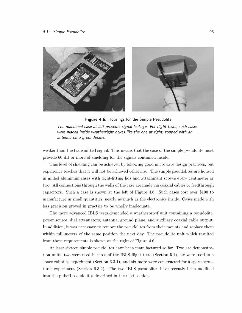
4.1: Simple Pseudolite 93
Figure 4.6: Housings for the Simple Pseudolite
The machined case at left prevents signal leakage. For flight tests, such caseswere placed inside weathertight boxes like the one at right, topped with anantenna on a groundplane.
weaker than the transmitted signal. This means that the case of the simple pseudolite must
provide 60 dB or more of shielding for the signals contained inside.
This level of shielding can be achieved by following good microwave design practices, but
experience teaches that it will not be achieved otherwise. The simple pseudolites are housed
in milled aluminum cases with tight-fitting lids and attachment screws every centimeter or
two. All connections through the walls of the case are made via coaxial cables or feedthrough
capacitors. Such a case is shown at the left of Figure 4.6. Such cases cost over $100 to
manufacture in small quantities, nearly as much as the electronics inside. Cases made with
less precision proved in practice to be wholly inadequate.
The more advanced IBLS tests demanded a weatherproof unit containing a pseudolite,
power source, dial attenuators, antenna, ground plane, and auxiliary coaxial cable output.
In addition, it was necessary to remove the pseudolites from their mounts and replace them
within millimeters of the same position the next day. The pseudolite unit which resulted
from these requirements is shown at the right of Figure 4.6.
At least sixteen simple pseudolites have been manufactured so far. Two are demonstra-
tion units, two were used in most of the IBLS flight tests (Section 5.1), six were used in a
space robotics experiment (Section 6.3.1), and six more were constructed for a space struc-
tures experiment (Section 6.3.2). The two IBLS pseudolites have recently been modified
into the pulsed pseudolites described in the next section.

94 Chapter 4: Pseudolite Designs
MC68HC11Microprocessor
Antenna
SimplePseudolite
EpochPulse
DataModulation
PINSwitch
PINSwitch
TransmitPulse
Amp
Figure 4.7: Block Diagram of the Pulsed Pseudolite
4.2 Pulsed Pseudolite
The simple pseudolite is subject to the near/far problem described in Section 3.2. Because
it transmits a continuous signal, its coverage area is limited to about a 10:1 range ratio.
Tests of the APL concept (Section 5.3) demanded pseudolites with a larger coverage area.
Accordingly, a pair of simple pseudolites were modified to transmit in high-powered pulses
with a duty cycle of 10 to 12.5 percent. At the same time, data modulation was added to
the signal, making it compatible with a new series of receivers.
The RTCM-104 pulse pattern was chosen because it has minimal spurious frequency
sidelobes. Due to its complexity, this pulse pattern was implemented inside a Motorola
68HC11 microprocessor. The same microprocessor generated the data modulation, after
formatting the data into the ICD–200 format and computing parity. The microprocessor
synchronized itself to a pulse generated by the simple pseudolite at the beginning of each
C/A code epoch.
The “near” radius for a pulsed pseudolite may be determined by the signal leakage when
the pulse is off. The quality of the pseudolite case, discussed above, becomes even more
important for a pulsed pseudolite. For the switches used to generate the pulse, the specified
isolation in the off state is crucial. If the pseudolite is intended to cover a wide area, the
specified power handling capability of the switches is also important. At least one switch
must be placed between the final power amplifier and the antenna, else the near radius will
be determined by the amplifier’s own internally generated noise level (kT +NF +Gain).
A block diagram of the pulsed pseudolite designed and constructed for the APL tests is

4.3: Synchrolite 95
shown in Figure 4.7. The isolation of the PIN diode switches used was only about 60 dB
each at L1; it was necessary to cascade two of them to achieve the required 90 dB isolation.
(These switches were acquired surplus for $3 each, a small fraction of their original cost.)
The external amplifier ($200) boosted the output signal to +10 dBm, or 10 mW.
4.3 Synchrolite
A synchrolite is a pseudolite whose transmitted signal is synchronized to the signal received
from a given GPS satellite (Section 2.4). A synchrolite must therefore contain a GPS
receiver, which must not be jammed by the transmitted signal. (A synchrolite which receives
and transmits through the same antenna presents the limiting worst case of the near/far
problem.) Due to the extreme difference in signal levels between the receiver and transmitter
(up to 160 dB), the only practical solution is to transmit in short pulses and receive between
pulses. The designs of both the transmit and receive sides of the synchrolite must take into
account the concerns addressed in the previous chapter regarding pulsed transmissions.
Receivers are generally harder to design and debug than transmitters. In constructing
the first synchrolite, it therefore made sense to attach a new transmitter to an existing
receiver. The receiver chosen for the task was a Trimble TANS, which had two advantages
for this project. First, the TANS RF stage was not highly integrated, so that rerouting its
signal paths was relatively easy. Second, the code and carrier signals for each channel were
available as test outputs on the correlator chips.
The TANS RF stage converts the incoming GPS signal at the L1 frequency down to a
nominal IF of 4.092 MHz by mixing it with a LO signal at 1571.328 MHz. The correlator
chips generate a “carrier” signal at the IF frequency and a C/A code signal at a nominal
1.023 MHz. Both code and carrier frequencies can be adjusted within a narrow range to
track the motion of a satellite, and both can be routed to output pins on the correlator
chips when a certain test mode is activated.
All three signals (LO, code, and carrier) are picked off the TANS receiver and recombined
in the synchrolite transmitter hardware. In practice, the C/A code transmitted by the
synchrolite must differ from the received satellite code, so that a user receiver can tell
the two signals apart. To accomplish this, new receiver software slaves a second correlator
channel to the first and commands it to generate a new C/A code. The transmitter hardware
combines the carrier from the master channel with the C/A code from the slave channel,

96 Chapter 4: Pseudolite Designs
T/R switch
TransmitAmp
Antenna
TransmitC/A CodeGenerator
ReceiveC/A CodeGenerator
IFCarrier
Generator
MicrowaveLocal
Oscillator
TransmitUpconverter
TrackingLoop
Controller
ReceiveAmp (LNA)
ReceiveMixer
CarrierWipeoff
CodeWipeoff
TransmitModulator
Figure 4.8: Block Diagram of the First Synchrolite
The first synchrolite was constructed by adding a synchronous transmitter(shaded boxes) to an existing GPS receiver.
then modulates the combination onto an amplified copy of the LO signal. This produces
the desired L1 synchrolite signal, with a new C/A code but the same timing as the incoming
satellite signal. This synchrolite was tested in two slightly different forms: the Autonomous
Integrity Beacon (AIB) and the Airport Pseudolite (APL).
4.3.1 Autonomous Integrity Beacon (AIB)
The AIB configuration required that the synchrolite transmit two separate reflections of a
single satellite signal, each through a separate antenna. This was accomplished by slaving a

4.3: Synchrolite 97
Figure 4.9: The Autonomous Integrity Beacon (AIB) Synchrolite
The Trimble TANS case containing the modified receiver is at the right of thepallet. In the center are the transmit upconverter and three PIN diodeswitches used for APL tests. At left are two batteries. Cables connecting thereceive and transmit antennas exit the sides of the photo.
second correlator channel to the master and duplicating the transmitting electronics. The
AIB synchrolite transmitted continuously; pulsing was not used.
One might expect interference in this configuration due to feedback from the transmit
antennas to the receive antenna. To avoid the possibility of such interference, the location
of the receive antenna was chosen so that local terrain features masked it from the transmit
antennas. The low transmit power levels used in IBLS (typically −40 dBm) also helped
reduce interference. If these two factors had not been sufficient, it would have been necessary
to pulse the transmitted signals.
Figure 4.9 shows the AIB during a flight test at Palo Alto airport. Flight test results
are discussed in Section 5.2.

98 Chapter 4: Pseudolite Designs
4.3.2 Airport Pseudolite (APL)
The APL configuration required that the synchrolite receive and transmit through a single
antenna, so that the satellite signal appeared to be “reflected” from a single point. It was
necessary to restrict the transmitter to short pulses once per C/A code epoch so that the
receiver would not be jammed. The Transmit/Receive (T/R) pulses and data modulation
were again generated by a MC68HC11 microprocessor. The T/R switches were the same
PIN diode switches used in the pulsed pseudolite described previously. The APL itself can
be seen in Figure 5.9.
Transmit pulse widths of 10 to 15 percent were used in the tests discussed in Section
5.3. An external amplifier ($400) used in most of these tests boosted the transmitted power
to +26 dBm or 400 mW. In one test, a helical antenna with a gain of about 11 dB brought
the effective isotropic radiated power (EIRP) in the beam up to +37 dBm or 5 Watts.
4.3.3 Problems with the First Synchrolite
Although the signal produced by this first synchrolite was adequate to demonstrate the con-
cept, it was far from perfect. The TANS receiver uses a single down-conversion to a low IF
frequency (4 MHz). The synchrolite transmitter perforce followed the same frequency plan.
Several attempts at constructing image-rejecting modulators were unsuccessful, and the final
transmitter circuit used a simple double-balanced mixer. The result was that the transmit-
ted signal contained an image signal about 8 MHz below L1, centered at 1567.236 MHz.
Figure 4.10 shows the output spectrum of the first synchrolite; compare this with the clean
signal from a simple pseudolite shown in Figure 4.5.
A second problem, not visible on a spectrum analyzer, is the discrete nature of the code
and carrier signals from the correlator chips. Both signals are generated by numerically
controlled oscillators (NCO) with single-bit outputs, clocked at 16 MHz. The smallest
possible change in the 4 MHz carrier output is 1/4 of a cycle, a phase step of π/2 radians.
The smallest possible change in the 1 MHz code phase is 1/16 of a chip. These comparatively
large steps can confuse user receiver algorithms designed to track continuous satellite signals.
Because of these signal flaws, the first synchrolite design is only useful to demonstrate
the concept. The following section describes design improvements for future synchrolites.

4.4: Synchrolite Improvements 99
Figure 4.10: Output Spectrum of the First Synchrolite
Note “image” signal and carrier spike to the left of the main L1 signal (center).
4.4 Synchrolite Improvements
The image signals in the first pseudolite could be removed with better filtering. A frequency
plan involving double or triple conversion will be necessary, because filters sharp enough to
remove the image after a single conversion are not presently cost-effective.
The transmit/receive switching can be accomplished much more effectively at lower
frequencies than at L1. Low-cost RF switches are available in surface-mount plastic packages
for about $3, but the package itself limits switch isolation at L1 to about 25 dB. The same
switches are capable of 60 dB or more isolation at 100 MHz.
To convert a signal to another frequency, it must be mixed with a LO signal at another,
properly chosen frequency. Each mixing operation generates the desired signal and an image

100 Chapter 4: Pseudolite Designs
signal on the other side of the LO. To transmit a clean, image-free signal, the image must be
filtered out. Limitations of current filter technology cause sharp filters with bandwidth less
than about 5 percent to be large and expensive. This, in turn, limits the size of the frequency
step which can be accomplished in a single conversion, making multiple conversions often
necessary.
The LO signals used in a synchrolite should all be generated from a common source,
preferably by multiplying or dividing the output of a single oscillator. None of the LO
frequencies should be multiples or fractions of a GPS code or carrier frequency, to avoid
corrupting the incoming signals with digital switching transients. These principles are
already well known in GPS receiver design, but they apply equally well to synchrolites.
Most GPS receivers today sample the analog IF signal with a single A/D converter at
a rate incommensurate with any of the received GPS signals. All subsequent processing is
done by digital logic clocked at the sampling rate. This architecture cannot generate synch-
rolite output signals with code phase edges which precisely match the edges of the received
satellite signal. Although the total error averaged over an epoch may be small, the transmit-
ted edges will always be asynchronous to the received edges because the receiver’s sampling
is asynchronous. This effect did not disturb the relatively low-performance receivers used
during the flight tests reported here. Narrow-correlator receivers, and those which attempt
to estimate code-phase multipath, may find such signals more confusing. In this case, it
may become necessary to build a synchrolite in which each receiver channel is sampled by
a separate quantizer synchronized to the received signal. Some form of self-calibration will
probably be necessary to prevent inter-channel bias.
For these and other reasons, the present crop of GPS correlator chips do not meet the
needs of synchrolites. It was simple luck that the code and carrier outputs were available as
test outputs on the TANS correlator chip. An improved synchrolite will require correlator
chips designed to produce signals as well as track them. Each correlator channel should
include a direct digital synthesizer (DDS) with a sine-wave output to replicate the GPS
carrier and another DDS to replicate the code clock. Receiver features discussed in Chapter
3 such as pulse blanking should also be added. The advent of large field programmmable
gate array (FPGA) chips has made it economically feasible to produce custom correlators
in small quantities and update their designs as needed. One would expect that the next
generation of synchrolites will be based on this technology.

4.5: Analog Synchrolites 101
4.5 Analog Synchrolites
The synchrolites described so far in this chapter track the GPS satellites signals individually
and then synthesize new signals with the same timing for transmission on the same L1
frequency. As Section 3.12 described, the L1 frequency is not available for general use.
Synchrolites intended for general use will need to transmit in another frequency band, and
their mating user receivers will require dual RF tuners to receive signals in both bands
simultaneously.
Once this is accepted, a new synchrolite design becomes possible: an “analog synchro-
lite” which receives the all the signals in the entire GPS band simultaneously, shifts them
in frequency, and retransmits them in another band. This actually a very old idea; simi-
lar devices known as “GPS translators” were used for years at military test ranges. The
translators were attached to expendable test vehicles such as missile nose cones, so that the
(then) expensive GPS receivers could remain undamaged on the ground. No one seems to
have noticed, until now, that a stationary translator makes an excellent DGPS reference
station for a mobile GPS receiver.
The analog synchrolite must contain an internal oscillator to perform the frequency
conversion. Any frequency error in this oscillator will corrupt differential carrier-phase
measurements (but not code-phase measurements) made from the signals reflected by the
synchrolite. A DGPS user receiver can calculate this frequency error using the code-phase
measurements with sufficient accuracy to remove it from the carrier-phase measurements.
Similar processing has been demonstrated during IBLS flight tests (Section 5.1).
The analog synchrolite does not interfere with the GPS satellite signals because it trans-
mits in a different band. Nevertheless, a near/far problem may still exist. A user receiver
near one analog synchrolite may attempt to measure signals from another, more distant
synchrolite. This new near/far problem, on a different band, can also be addressed by the
methods of Chapter 3.

102
�

Chapter 5
Pseudolite Flight Tests
Many of the concepts, theories, and devices described in previous chapters were tested in a
series of airborne experiments conducted by the author and fellow researchers. The primary
goal of these experiments was to develop, demonstrate, and improve the Integrity Beacon
Landing System (IBLS). The results form an existence proof of the speed, accuracy, and
reliability claimed for CDGPS navigation initialized by pseudolites.
5.1 Integrity Beacon Landing System (IBLS)
IBLS is a prototype carrier-phase differential GPS (CDGPS) navigation system which uses
pseudolites to initialize the carrier-phase integers. Researchers at Stanford University de-
signed IBLS to investigate the possibility that a CDGPS system could replace existing
aircraft navigation systems used for precision approach and landing in bad weather. Such
systems are subject to stringent performance requirements imposed by national and inter-
national aviation authorities.
5.1.1 Required Navigation Performance
The International Civil Aviation Organization (ICAO) specifies the Required Navigation
Performance (RNP) for a precision landing navigation system in four categories: accuracy,
availability, continuity, and integrity [44]. Accuracy is the expected accuracy of the naviga-
tion signal, generally specified as a 95% (µ+2σ) threshold. Availability is the percentage of
time that the system is performing within specifications. Continuity describes the probabil-
ity that any given landing attempt must be aborted due to a failure in the landing system.
103

104 Chapter 5: Pseudolite Flight Tests
Integrity describes the probability that the self-checking features of the landing system fail
to detect an error which exceeds system requirements.
An integrity failure means that the landing system is feeding false and potentially haz-
ardous information to the pilot and autopilot without their knowledge. In the worst cases,
this can happen close to the ground, in weather conditions which include poor visibility and
severe turbulence. It may be difficult for the pilot to detect and recover from a landing sys-
tem failure under these conditions. The specifications for integrity are therefore extremely
stringent: no more than one undetected failure in a billion landings. There have been no
aircraft accidents traceable to failures of the existing Instrument Landing System (ILS),
and this stringent requirement is intended to ensure that future replacements will maintain
an equally perfect record.
5.1.2 IBLS System Description
IBLS is a research tool designed to demonstrate that a pseudolite-assisted CDGPS naviga-
tion system can meet the RNP requirements for aircraft landing. Because IBLS is a research
and demonstration tool, flown only in good weather with a safety pilot in control, compar-
atively little effort was devoted to redundancy and reliability. Compliance with the ICAO
availability and continuity requirements was demonstrated by analysis [30] rather than by
actual testing. The goal of the IBLS flight tests, on the other hand, was to demonstrate
full compliance with the ICAO accuracy and integrity requirements.
The IBLS ground system includes a CDGPS reference receiver, a datalink from the
reference station to the aircraft, and a pair of Integrity Beacon pseudolites underneath the
aircraft’s final approach to the runway. The pseudolites transmit overlapping, hemispherical
signal “bubbles” which the aircraft flies through just before landing.
The IBLS ground reference receiver continuously tracks signals from the two pseudolites
and at least four GPS satellites, and transmits time-tagged sets of simultaneous measure-
ments to the aircraft via the datalink. Both directional antennas and coaxial cables have
been used to convey the pseudolite signals to the reference receiver.
When the IBLS ground system is first installed, the locations of the reference antenna
and the two Integrity Beacon pseudolite antennas are computed with respect to the runway
aimpoint using conventional GPS static survey equipment with sub-centimeter accuracy.
All subsequent navigation depends on the accuracy of this survey.

5.1: Integrity Beacon Landing System (IBLS) 105
Runway
Pseudolitepseudorange
vectorsGlidepath
GPS Satellites
IBLSreferencestation
Satellitepseudorange
vectors
Integrity Beaconpseudolites
IBLS datalink
IBLSuser
Pseudolitesignal
"bubbles"
Figure 5.1: Overview of the Integrity Beacon Landing System (IBLS)
The aircraft initializes centimeter-accurate CDGPS navigation by analyzingsignals from the Integrity Beacons collected on final approach.
The IBLS aircraft system includes a CDGPS user receiver and a computer to carry out
the IBLS algorithms. The user receiver has two antennas: one facing up to collect satellite
signals, and one facing down to collect pseudolite signals.
The aircraft navigates down the glidepath to the Integrity Beacons using conventional
differential code-phase GPS. As it flies through the Integrity Beacon signal bubbles, it
collects differential carrier-phase measurements of the satellite and pseudolite signals. Each
time-tagged set of measurements becomes a row in a large matrix. Because the line-of-sight
vectors from the pseudolites to the aircraft are rapidly changing, the matrix is non-singular
and can be solved.
As the aircraft leaves the bubbles, it solves the matrix to find the carrier-phase integers
and the measurement residuals. If the residuals exceed a certain threshold, an error has

106 Chapter 5: Pseudolite Flight Tests
occurred and the approach is aborted; this is the fundamental integrity monitor in IBLS.
This threshold can be set so that the probability of an undetected navigation failure sat-
isfies any given integrity requirement [30], although availability and continuity of landing
navigation may be reduced.
Ordinarily, the residuals will be less than the threshold. The aircraft then continues
down to a safe landing, using the CDGPS with the integers just computed to navigate
with 1σ accuracy of approximately 1 cm. As a backup integrity check, the IBLS computer
continuously checks the residuals from the real-time position calculations against another
threshold. This is a version of Receiver Autonomous Integrity Monitoring (RAIM), a tech-
nique pioneered by Axelrad and Parkinson [45].
Lawrence [29] provides a detailed discussion of IBLS equations and algorithms used in
the real-time flight software. Pervan [30] describes the algorithms used during and after
the “bubble pass” to resolve the integer cycle ambiguities. In the same work, Pervan shows
by analysis and tests that IBLS greatly exceeds the ICAO required navigation performance
(RNP) for fully automatic landings. Please refer to these works for further details on these
topics.
5.1.3 IBLS Flight Tests
The IBLS research group at Stanford University performed three years of flight tests of this
system, including many hundreds of approaches in four different aircraft on two continents.
These tests are described in great detail in a number of papers written during the develop-
ment of the system [46, 47, 48, 49, 50, 51, 52, 53, 54]. This section can only highlight these
tests; please refer to the listed papers for more details.
All the tests described in this section used Integrity Beacons which transmitted a contin-
uous signal, with no electronic means to alleviate the near/far problem. Instead, the signal
power levels transmitted by the beacons were carefully coordinated with the aircraft’s flight
path, so that the beacon signals were never strong enough to interfere with the satellite
signals. A direct consequence is that the beacon signals were only strong enough to be
detected within a sphere or “bubble” centered on the beacon. This does not affect the IBLS
system, because most of the geometry change during an IBLS approach takes place within
the bubbles.
One possible problem with this scheme is that the aircraft’s receiver must acquire the
beacon signals within a few seconds after they become strong enough to detect; otherwise,

5.1: Integrity Beacon Landing System (IBLS) 107
Figure 5.2: IBLS Flight Test Aircraft: Piper Dakota
Professor David Powell flies his Piper Dakota (N4341M) on an IBLS testapproach to Palo Alto Airport with NASA Administrator Dan Goldin aboard.
too much of the geometry change will be missed and the ambiguity resolution process
may not succeed. This problem was solved with a feedforward technique known as code
phase aiding described in Section 3.10.1. Properly shaped antenna patterns, as described
in Section 3.4.2, might also be useful in future systems but were not used for these tests.
Another possible problem is that, unlike the current ILS, an IBLS aircraft cannot detect
the ground-based signals which will allow it to land until it has already committed to the
approach. This is not a problem at the technical level, but it makes pilots uncomfortable
and may pose operational or administrative difficulties. Integrity Beacons which transmit
more powerful signals can solve both these problems, provided that the near/far problem
is solved by one of the techniques discussed in Chapter 3. Section 5.3 below discusses tests
of pulsed pseudolites which could be used as Integrity Beacons.
Figure 5.2 shows a Piper Dakota owned by Stanford professor David Powell and used for
many of the IBLS flight tests. This aircraft, registration number 4341M, was progressively
modified to support flight tests involving GPS. It eventually mounted a total of eight GPS
antennas, two UHF datalink antennas, one Inmarsat antenna for satellite communications,
and a Loran navigation antenna, in addition to the standard ILS and other equipment

108 Chapter 5: Pseudolite Flight Tests
required for operation under Instrument Flight Rules. A retroreflector was mounted at
the tip of the vertical tail, which allows a laser tracking system to measure the Dakota’s
position, and a laser altimeter was occasionally mounted in the belly of the plane.1
This well-equipped light plane was used for most of the IBLS development tests. First
one, then two Integrity Beacons were installed at Palo Alto airport (PAO). The first tests
simply recorded signal data from the air and ground reference receivers; post-processing
this data showed that the concept was sound [46]. The installations were then upgraded
with a datalink and new software to permit real-time tests.
The first real-time test of a full IBLS system took place on 23 July 1993. The Dakota
overflew a pair of Integrity Beacons on the Stanford campus, then landed and parked at
PAO. Commercial GPS surveying equipment measured the airplane’s parked position; the
result matched the final IBLS position within 2 cm [47].
The next test, during the week of 12 August 1993, used a laser altimeter to verify the
vertical accuracy of the system [49]. Fifteen touch-and-go landings were performed. The
mean difference between the IBLS position and the laser altimeter’s reading, during the
times the laser reading was reliable, was 1.5 cm and the standard deviation was 7 cm. The
specified accuracy of the laser was ±5 cm.
After another round of upgrades, the IBLS system (then called the Kinematic GPS
Landing System) was ready for a more formal test, which took place during the week of 25
August 1993. NASA researchers allowed the IBLS team to perform a series of approaches
at their Crow’s Landing facility, where the Dakota could be tracked by radar and laser
measuring devices. The goal was to measure the dynamic accuracy of IBLS under actual
flight conditions. The specified accuracy of the laser tracker was about 1 foot RMS, and the
test results showed that IBLS was at least that accurate [47]. It was impossible to measure
directly the actual accuracy of IBLS in this test, although the behavior of the residuals
implied that the error level was on the order of 2 cm RMS.
Almost all the tests up to this point were conducted using commercial GPS signal
generators as the Integrity Beacons. These bulky devices required 110 VAC power which
was difficult to provide in the field, and the signals they generated were extremely weak.
The desire for a pseudolite better adapted for use as an Integrity Beacon inspired the design
of the simple pseudolite (Section 4.1).1This aircraft, known to all as “Mike,” unfortunately was destroyed in a hard landing while this disser-
tation was being prepared. Those of us who knew Mike will miss him.

5.1: Integrity Beacon Landing System (IBLS) 109
Figure 5.3: IBLS Flight Test Aircraft: FAA King Air
FAA Administrator David Hinson flies an IBLS auto-coupled approach toAtlantic City International Airport in the FAA’s Beechcraft King Air (N35).
These new Integrity Beacons were part of the next IBLS flight test, which took place in
during July 1994 at the FAA Technical Center in Atlantic City, New Jersey. In this test,
the IBLS position signals were used to guide an aircraft down the approach path almost to
touchdown.
The prototype IBLS was installed in a Beechcraft King Air owned by the FAA, shown
in Figure 5.3. IBLS position and guidance data were transmitted in real-time to an existing
data-collection system on the aircraft. This system converted the IBLS signals to a digital
avionics format and fed them to the autopilot disguised as ILS signals.
The King Air autopilot is designed to follow ILS signals along a landing approach down
to the “Category I decision height” at 200 feet altitude, at which point the pilot is supposed
to resume control and land manually. This is known as an autocoupled approach. During
the official test series, 27 July–2 August 1994, 49 autocoupled approaches were attempted
using IBLS guidance in place of ILS. All 49 approaches were successful. IBLS guidance was
so smooth that one test pilot repeatedly allowed the autopilot to continue the approach
down to about 20 feet altitude (below the Category IIIa decision height) before resuming
control. The FAA Administrator, David Hinson, personally flew two of the approaches and
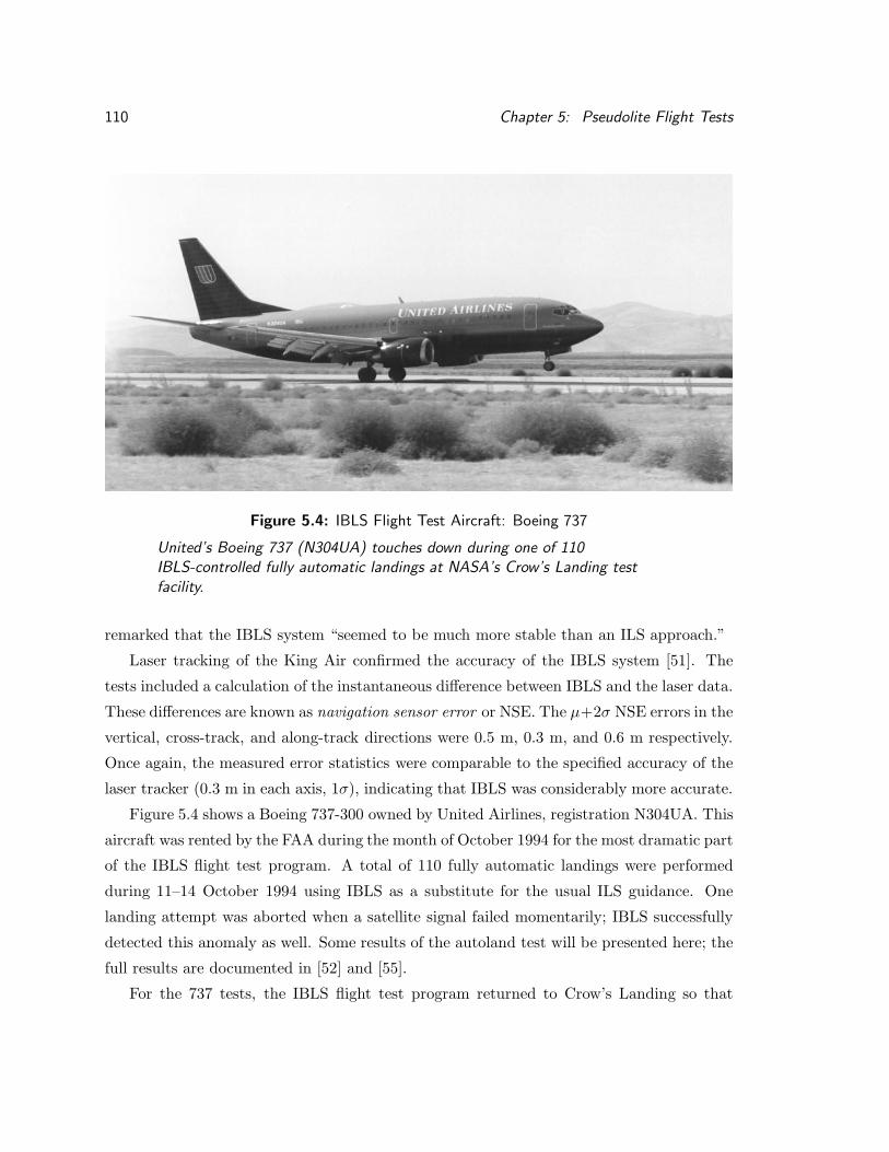
110 Chapter 5: Pseudolite Flight Tests
Figure 5.4: IBLS Flight Test Aircraft: Boeing 737
United’s Boeing 737 (N304UA) touches down during one of 110IBLS-controlled fully automatic landings at NASA’s Crow’s Landing testfacility.
remarked that the IBLS system “seemed to be much more stable than an ILS approach.”
Laser tracking of the King Air confirmed the accuracy of the IBLS system [51]. The
tests included a calculation of the instantaneous difference between IBLS and the laser data.
These differences are known as navigation sensor error or NSE. The µ+2σ NSE errors in the
vertical, cross-track, and along-track directions were 0.5 m, 0.3 m, and 0.6 m respectively.
Once again, the measured error statistics were comparable to the specified accuracy of the
laser tracker (0.3 m in each axis, 1σ), indicating that IBLS was considerably more accurate.
Figure 5.4 shows a Boeing 737-300 owned by United Airlines, registration N304UA. This
aircraft was rented by the FAA during the month of October 1994 for the most dramatic part
of the IBLS flight test program. A total of 110 fully automatic landings were performed
during 11–14 October 1994 using IBLS as a substitute for the usual ILS guidance. One
landing attempt was aborted when a satellite signal failed momentarily; IBLS successfully
detected this anomaly as well. Some results of the autoland test will be presented here; the
full results are documented in [52] and [55].
For the 737 tests, the IBLS flight test program returned to Crow’s Landing so that

5.1: Integrity Beacon Landing System (IBLS) 111
500 450 400 350 300 250 200 150 100 50 0−5
−4
−3
−2
−1
0
1
2
3
4
5
Nominal Altitude for 3 Degree Glideslope (ft)
Ver
tical
NSE
(ft
)
Laser AccuracyLaser Accuracy
Figure 5.5: IBLS Vertical Navigation Sensor Error (VNSE)
Instantaneous vertical position difference between IBLS and a laser trackerduring 110 automatic landings of a Boeing 737 controlled by IBLS.
NASA’s laser tracker could be used once again. Figure 5.5 shows the NSE in the vertical
axis for all 110 landings, along with the specified 1σ accuracy of the laser tracker. The
overall µ+ 2σ NSE errors were 0.2 m vertical and 0.4 m cross-track.
A system for automatic landings must bring the aircraft to a safe touchdown within a
defined area on the runway. Figure 5.6 shows the actual locations of the 110 touchdowns
measured during this test superimposed on the “touchdown box” defined by an ICAO
requirement. IBLS easily met this requirement, which states that 95% of the touchdowns in
any given test must fall within the box shown. In fact, a box drawn around 95% of the actual
IBLS touchdown points is half the size of the requirement box in each dimension. These
results were obtained over four days of testing, including one day in which the published
crosswind limits for the autoland mode of the autopilot were exceeded by a considerable
margin. This performance clearly shows the potential of ILBS as a future aircraft navigation

112 Chapter 5: Pseudolite Flight Tests
−1000 −500 0 500 1000 1500 2000−75
−50
−25
0
25
50
75
Along Track Position (ft)
Cro
ss T
rack
Pos
ition
(ft
) 95% Touchdown Box
IBLS Boeing 737 Touchdown Dispersions
95% Touchdown Box
AimPoint
Figure 5.6: IBLS Touchdown Box
Boeing 737 position at main gear touchdown during 110 automatic landingscontrolled by IBLS. The left, top, and bottom borders of the graph match theedges of the actual runway. ICAO requires 95% of the touchdown points to fallwithin the box shown. All IBLS touchdowns fell within this box.
system.
Throughout the IBLS tests, the claim has been made that IBLS is considerably more
accurate than laser trackers. This claim is justified in part by data such as that shown in
Figure 5.7. The aircraft was parked in the touchdown area of the runway for several minutes
with both IBLS and the laser tracker running exactly as they had in flight, while data was
collected from both systems for calibration purposes. The figure shows the relative error
magnitudes for the laser tracker and IBLS, justifying the above claim.
Although not a formal test series, the prototype IBLS was installed in a Dornier 129
owned by the Technical University of Braunschweig, Germany, for a flight demonstration

5.2: Autonomous Integrity Beacon (AIB) 113
−6.5 −6 −5.5 −50.8
1
1.2
1.4
1.6
1.8
2
Along Track (ft)
Ver
tical
(ft
)
Figure 5.7: Laser Tracker Errors during IBLS Autoland Test
Laser tracker position noise (bottom left) versus IBLS noise (top right) withtest aircraft parked on runway. (Center positions offset for clarity.)
held as part of the ISPA–95 conference held 21–24 February 1995. Quantitative data was
not available from this demonstration, but the system performed well in a qualitative sense.
5.2 Autonomous Integrity Beacon (AIB)
The process of installing IBLS at several different research sites created a desire for certain
improvements. In particular, the need for the ground reference receiver to directly sense the
pseudolite signals proved remarkably inconvenient in practice. The Autonomous Integrity
Beacon (AIB) described in Section 4.3.1 was designed to remedy this particular problem.
The AIB is a synchrolite implementation which generates two pseudolite signals with
the same timing as a given satellite signal. The same satellite signal is simultaneously

114 Chapter 5: Pseudolite Flight Tests
0 0.05 0.1 0.15 0.2 0.25 0.3 0.35 0.4 0.45 0.50
1
2
3
4
5
6
7
8
Integer Error (cycles)
Num
ber
of O
ccur
ence
s
Figure 5.8: Histogram of Integer Differences during AIB Flight Tests
measured by the IBLS reference station. The IBLS computer in the aircraft can use this
measurement, with knowledge of the relative antenna positions, to synthesize a reference
carrier phase measurement for each Integrity Beacon antenna. Subtracting this synthetic
reference from the measured signal gives the differential carrier-phase measurement from
each Integrity Beacon needed by the IBLS algorithms.
The IBLS ground reference receiver used with the AIB is no longer tied to the Integrity
Beacons but can be placed at any convenient location. The original plan was to locate
the reference station near the runway to optimize datalink coverage during touchdown and
rollout. For the flight tests described here, only the datalink transmitter was placed near the
runway. The reference receiver remained in the IBLS laboratory on the Stanford campus,
6 km away, and communicated with the datalink transmitter via telephone modem.
The prototype AIB was tested for a total of eleven landing approaches during two days
[54]. Each day of testing began with a static survey which determined the carrier-phase
integers in the IBLS receiver for later comparison. During each approach, the aircraft
flew through the AIB signal “bubbles” and then performed a touch-and-go landing. After
each pass through the bubbles, the IBLS software processed the bubble data to resolve the
carrier-phase integers.
Each bubble pass was successful in that the IBLS real-time integrity checks declared
that the system had successfully estimated the carrier-phase integers. The system actually
estimates each integer as a floating-point number; one measure of the quality of the Integrity

5.2: Autonomous Integrity Beacon (AIB) 115
Figure 5.9: Testing the Airport Pseudolite (APL) Synchrolite
The APL flight test and near/far test were performed simultaneously. Here,the author positions the two handheld GPS receivers used for the “near” testnext to the APL’s transmit/receive antenna. Foliage visible in the backgroundmay have partially blocked the APL signal at long ranges.
Beacon signals is the difference between these computed numbers and the actual known
integers determined by the preflight static survey.
A histogram of these differences, for all the integers estimated during the AIB test, is
shown in Figure 5.8. All differences are safely below the theshold of 0.5 which could cause
an error in calculating the integers. The errors probably would be smaller, were it not for
the known signal flaws in the prototype synchrolite described in Section 4.3.3.

116 Chapter 5: Pseudolite Flight Tests
5.3 Pulsed Synchrolite (APL)
The original Integrity Beacon pseudolites used for the IBLS flight tests were short-range
transmitters limited by the near/far problem. Longer-range pseudolites would greatly ben-
efit both aircraft landing applications [29, Chapter 7] and other CDGPS applications yet
unknown. As part of this research, a number of pseudolites were designed and constructed
which used pulse transmission techniques (Section 3.6) to ameliorate the near/far problem.
First, a pulsed synchrolite was constructed and tested. Later, the original Integrity Bea-
con pseudolites were modified for pulsed transmissions. Flight test results for the APL are
presented here; the pulsed pseudolites were not quantitatively tested during this research.
The original AIB synchrolite was modified to receive and transmit through the same
antenna, “reflecting” a given satellite signal from a known point on the ground (Section
4.3.2). With a high-power amplifier and pulse switches added, this became known as the
Airport Pseudolite (APL). Figure 5.9 shows the APL in operation.
Several flight tests of the pulsed synchrolite APL were conducted [54]. The most signif-
icant of these was the minimum/maximum range test. The goal of this test was to quantify
the ability of pulsed transmissions to solve the near/far problem.
The pulsed APL transmitter was varied up to +26 dBm or 0.4 Watts output power. A
PIN diode switch followed the final amplifier, to ensure that no signal, not even thermal
noise, was transmitted during the pulse “off” periods. The flight test aircraft maneuvered
over the AIB at various altitudes to measure the characteristics of the pulsed bubble, and
departed from the local area to measure the characteristics at longer ranges. Figure 5.10
summarizes the results of this test, with previous results from non-pulsed Integrity Beacon
pseudolites included for reference.
The solid lines in Figure 5.10 show the theoretical range calculated for each transmitted
power level, pulsed and non-pulsed. These calculations are based on the simplified Friis
range equation
L =GtGr
(4π)2
(λ
r
)2
where L is the path loss, Gt and Gr are the gains of the transmit and receive antennas
respectively, λ is the L1 wavelength (∼0.19 meters), and r is the distance between anten-
nas. The black line assumes a continuous transmission; the gray line assumes a pulsed
transmission with a duty cycle of 1/8. Both lines assume antenna gains of 0 dBic at both

5.3: Pulsed Synchrolite (APL) 117
100
101
102
103
104
105
-80
-60
-40
-20
0
20
40
Range (m)
Tra
nsm
it P
ower
(dB
m)
Data
Theory
Pulsed
Continuous
Figure 5.10: Power Required versus Distance Transmitted for Pulsed APL
The lines show the theoretical power required for a given distance; the crossesare data points from actual flight tests. Data shown in black are for continuoustransmission, and the gray data are for 12.5% duty cycle pulsed transmissions.
the transmitter and receiver. The gain of real antennas varies with elevation, but this graph
does not reflect this effect.
The crosses in Figure 5.10 show the actual data points measured during this APL test
as well as several IBLS tests with non-pulsed Integrity Beacons. The graph shows that
a maximum range of 18 km was achieved with the pulsed APL. The transmitted power
level required to actually achieve this range is about 25 dB higher than the power level
theoretically required. At long range, the APL signal travels in a nearly horizontal direction,
which cause additional path loss due to a combination of factors:
• The antenna patterns for the transmit and receive antennas have much lower gain
118 Chapter 5: Pseudolite Flight Tests
near the horizon than near the zenith. At the longest ranges, each antenna’s gain was
approximately −6 dBic2 giving a total additional path loss of −12 dB.
• At the lowest angles, the line-of-sight path from the APL to the aircraft was partially
obscured by the foliage seen in the background of Figure 5.9. It is well known that
foliage attenuates GPS signals [1, Chapter 15]. The actual attenuation in this case
is difficult to compute, but 6 dB of attenuation would be a reasonable estimate.
This effect could be eliminated in permanent APL installations by improved siting or
landscaping procedures.
• Radio signals which travel parallel to lossy surfaces such as soil (known as ground
waves) are subject to higher attenuation than signals which travel through free space.
The low transmission angles at longer ranges may have allowed this effect to partially
attenuate the APL signal.
These factors must be taken into account when computing the required transmit power
level for new pseudolite installations. Because some are difficult to estimate, it is best to
measure signal strength throughout the coverage area after installation.
While Figure 5.10 shows the “far” radius, the “near” radius, at which interference with
the satellite constellation begins, is equally important. Pulsed transmissions inevitably
interfere with the satellite signals for the duration of the pulsed transmission. This effect is
entirely determined by the pulse duty cycle and is constant throughout the coverage area. A
near radius, within which satellite signals experience excess interference, can only be caused
by deviations from the theoretical ideal of a pulsed transmitter and a saturating receiver.
In practice, such deviations can include:
• transmitter leakage caused by imperfect pulse switches
• in-band thermal noise from unswitched transmit amplifiers
• slow receiver AGC or other receiver saturation effects (Section 3.6.2)
During the long-range APL test described above, an attempt was made to quantify
the near radius. Hand-held GPS receivers, used for convenience, were brought as close
as possible to the APL transmit antenna while monitoring the displayed satellite signal2This estimate is based on gain patterns for similar microstrip patch antennas; the gain pattern for the
antennas actually used was unavailable.

5.3: Pulsed Synchrolite (APL) 119
Figure 5.11: Near/Far Problem Overcome
An aircraft 18 km away from this synchrolite antenna measures its signal whilethese handheld receivers 18 cm away show minimal interference.
strengths for excess interference. Two different hand-held receivers were used. Neither
receiver experienced excess interference from the APL, even at when placed at the rim of
the APL antenna’s ground plane, approximately 18 cm from the antenna phase center. This
result implies a near/far range ratio in excess of 100,000:1 or 50 dB, equivalent to a power
ratio greater than 100 dB.
Figure 5.11 shows the hand-held receivers during this test. The vertical bars along the
bottom of the display on the Garmin receiver (at left) correspond to signal strengths of the
satellites being tracked—note that most are near their maximum values. Other indications
on the display show that the receiver is navigating with an estimated error of 92 feet in
3 dimensions. The Trimble receiver (at right) is reporting “6 satellites” being tracked and
is continuously performing position fixes.
These photographs was taken just after the maximum range test (18 km) with no changes
to the APL configuration. The only interference detected was the unavoidable loss of
satellite signal power due to the 12% duty cycle of the pulsed transmissions themselves. This
loss produced a barely visible change on the signal strength graphs as the APL transmitter
was enabled and disabled.
The receiver contained within the APL shares an antenna and cabling with the APL
transmitter. This receiver is perhaps the most likely to experience any near radius inter-
ference from the transmitter. No such interference was seen during any operational test of

120 Chapter 5: Pseudolite Flight Tests
the APL. Neither was excess interference seen by the receiver aboard the test aircraft.
All the receivers tested during this experiment used single-bit signal processing (hard
limiting). Although not documented here, similar experiments with multiple-bit receivers
have produced similar results.
Tests of the pulsed synchrolite used the IBLS aircraft system for convenience, although
the IBLS technique itself was not being tested. As the test aircraft maneuvered over the
APL, the IBLS software attempted to resolve the carrier phase ambiguities using the signal
from the single APL in place of the usual two Integrity Beacon signals. These attempts at
integer resolution each converged to an answer, but the answers generally were not precise
enough to uniquely identify the integers because of the poor geometry. Each attempt did
correctly update the position covariances, however, and after several attempts the solution
converged on the correct integers. This result, repeated several times and confirmed in
post-processing, shows the robustness of the IBLS technique for CDGPS navigation in a
large space. Even a primitive synchrolite provides a signal adequate to reliably resolve the
carrier-phase integers.
These results demonstrate that a properly implemented pulse transmission scheme can
provide a near/far ratio adequate for virtually any pseudolite application.

Chapter 6
Pseudolite Applications
The previous chapter demonstrated the advantages of pseudolite-based CDGPS for aircraft
precision approach and landing navigation. This is one of the most demanding navigation
applications known; it seems reasonable that a system which can meet such stringent re-
quirements might have many other applications. This chapter presents a variety of GPS
applications which low-cost pseudolites make possible.
6.1 Aircraft Applications
Even without considering the precision landing problem, aviation presents some of the most
demanding technological challenges known. The accuracy and speed of pseudolite-based
CDGPS systems make them favored contenders for a number of existing and speculative
applications.
6.1.1 Flight Inspection
Unless and until a new aircraft landing system is universally adopted, the existing landing
systems will remain in place and in use. These systems must be periodically monitored,
calibrated, and certified for continued use. This process is known as flight inspection.
Specialized aircraft fly nominal and off-nominal approaches to landing while recording the
signals received from the navigational aids or navaids being inspected. These navaid signals
are compared to the actual position of the aircraft during the approach, recorded by a
separate “truth” measurement system.
121

122 Chapter 6: Pseudolite Applications
As a rule of thumb, a source of data for calibration must be ten times more accurate
than the system being calibrated. The truth systems used to inspect Category III navaids
include optical theodolites and laser trackers. These are expensive and cumbersome to use,
but they have been the only systems with sufficient accuracy available until now.
A truth system derived from IBLS is ideal for this application. Chapter 5 demonstrated
that IBLS provides positions which are at least as accurate as a good laser tracker. Com-
pared to previous methods, IBLS is inexpensive and easily installed. This research has
demonstrated that a pair of workers can install an IBLS system from scratch in a few
hours. If permanent antenna mounts are installed at a given site, installation time could be
only a few minutes. If necessary, the system design parameters of IBLS can be adjusted to
favor accuracy and integrity over availability and continuity; flight inspection can tolerate
the occasional loss of an approach in the quest for more accuracy.
Flight inspection appears to be an excellent starting point for IBLS applications in
aviation. Experience gained in the operation of such a system could be directly applied to
the design of a full-up IBLS for general use. A more detailed description of the benefits of
IBLS for flight inspection is presented in [56].
6.1.2 Accuracy in Thirteen Dimensions
The precise positioning available from CDGPS systems can be combined with equally pre-
cise GPS attitude determination [40] to provide thirteen dimensions of extremely accurate
navigation data. A properly configured GPS system can directly measure three dimen-
sions each of position and velocity with centimeter accuracy, plus three dimensions each
of attitude and angular rate with milliradian accuracy. All these measurements are made
simultaneously and time-tagged with sub-microsecond accuracy. A single receiver can make
50 or more sets of measurements per second. Such a comprehensive set of navigation data
has rarely been available in the past at any price; now it can be had for a few thousand
dollars. This capability will revolutionize many fields, not a few of which are part of aviation.
The process of designing and testing new aircraft requires precise information about
both the straight-line performance (cruise speed, rate of climb, etc) and the stability and
control parameters governed by various aerodynamic coefficients. Collecting this informa-
tion has been a tedious task because the sources of data were limited. A thirteen-dimension
navigation receiver would improve both the quality of the test results and the time taken
to obtain them.

6.1: Aircraft Applications 123
Figure 6.1: IBLS for Flight Inspection
IBLS can be used to calibrate existing navigational aids more precisely,improving the safety margins of airline travel.
Aerobatic competitions are currently judged by referees on the ground, who must apply
their skilled intuitions to extrapolate the three-dimensional position of a competing aircraft
from their own two-dimensional views of the event. An “instant replay” display with cen-
timeter accuracy, viewable from any angle, could clearly mark any violations of the rules or
requirements, while improving both the actual and perceived fairness of the judging. The
less demanding but far more common process of training new pilots could also benefit from
such displays, as could air combat training, either in the military world or in the civilian
fantasy fighter schools.
Finally, this technology could substantially increase the audience for air racing. This
sport, in which a single lap covers many miles and most of the action takes place out of
sight, is notoriously difficult for spectators and television viewers to appreciate. Data from
a navigation set in each airplane could be downlinked to generate a continuous display of
the race as seen from the cockpits, or from a “god’s-eye view” following the leaders. Such
technology could raise the ratings of air racing just as it already has for the America’s Cup

124 Chapter 6: Pseudolite Applications
sailboat races, improving the sport’s prestige, funding, and technological progress.
6.2 Land Applications
It is not uncommon for land vehicles to require guidance accurate within a centimeter or
two. Farm implements must follow the furrows in the field; mining equipment must excavate
the right seam; construction equipment must grade a road level enough to prevent puddles.
While the accuracy requirements for this sort of work may be even tougher than for aircraft
landing, the integrity, continuity, and availability requirements are much looser. No one
will die if a farm tractor shuts down for a few minutes because a satellite failed.
6.2.1 Robotic Tractors
To avoid damaging the crop, a farm tractor must be driven precisely, so that the implements
towed behind it hit the furrows while the wheels of the tractor do not. A tractor must be
driven over each furrow of each field several times per year to turn the soil, to spread seeds,
fertilizer, and pesticides, and finally to harvest the crop. These events frequently must be
completed within very short windows of time due to weather and calendar constraints. The
result is many long days and nights of driving tractors, with concentration demanded at
every moment.
To an engineer, this fatiguing and unrewarding task demands to be automated. Previous
attempts to do so have involved mechanical sensors which followed a furrow by tracking it
with a ball on either side. Such devices require straight furrows plowed initially by a
well-trained crew, and even then have been only partially successful. A CDGPS system,
augmented by pseudolites, could provide guidance to plow a field in any pattern.
The use of CDGPS tractor guidance allows other data tied to the same GPS reference
to be incorporated into a detailed farming strategy. Such data include digital terrain maps,
remote sensing photographs, and instantaneous yield measurements from a previous harvest.
All this data can be combined into a farming plan which meets the needs of each individual
square meter of each field, and CDGPS guidance can ensure that the plan is executed
properly. Such techniques, collectively known as precision farming, are revolutionizing
agriculture.
A leading tractor manufacturer has contracted with Stanford University to research and
develop a tractor guidance and control system based on CDGPS technology. To initialize

6.2: Land Applications 125
Figure 6.2: Robotic Tractor Controlled by CDGPS with Pseudolites
the carrier phase ambiguities, the tractor will drive past a pseudolite mounted on a fence-
post. Only a single pseudolite is required in most cases because only two dimensions of
position must be computed. Obviously, this system cannot be practical unless the cost of
the guidance system, including pseudolites, is small compared to the cost of the tractor.
Figure 6.2 shows Stanford researchers Tom Bell and Mike O’Connor with their prototype
robotic tractor. The results of their research to date are given in [57] and [58].
6.2.2 Mining
Open-pit mining involves removing vast quantities of overburden to reach a comparatively
thin seam of ore. The pit is dug in a precise manner, with a smooth spiral ramp following
the walls up to the surface. Large vehicles travel up and down the ramp, transporting the
ore and the overburden to their destinations. These vehicles are constantly in motion, and
driving them is a mind-numbing task. A guidance system based on CDGPS could automate
this task.

126 Chapter 6: Pseudolite Applications
The ore and overburden must be separated as well as possible before leaving the mine.
The shape of the mine pit must follow the seams of the ore, and the shape of the walls must
be controlled to prevent rockslides. All three of these tasks require precise control of the
digging process, which a CDGPS vehicle guidance system could also provide.
A leading manufacturer of earth-moving equipment has contracted with Stanford Uni-
versity to develop guidance systems based on pseudolite-assisted CDGPS for its digging and
transport vehicles. These systems must function at the base of the pit, where the sky may
only be visible for 30 degrees from the zenith and the visibility of GPS satellite signals is
correspondingly poor. To ensure reliable navigation, the GPS constellation must be aug-
mented by pseudolites around the rim of the pit. As many as six or eight pseudolites may
be required to ensure the availability of navigation anywhere within the pit. Once again,
low-cost pseudolites are required if this application is to become economically practical.
Figure 6.3 shows Stanford researcher Jonathan Stone with his research vehicles.
6.2.3 Automobiles
The forthcoming Intelligent Vehicle Highway System (IVHS) assumes that future automo-
biles will navigate themselves to some extent. In open countryside, where GPS satellites are
continuously visible, this requirement is easily met. However, automobiles must also travel
through tunnels and urban canyons, where the GPS signals are rarely if ever available.
Pseudolites placed in strategic locations could help solve this problem, making the benefits
of IVHS more widely available.
6.2.4 Speculations
The different applications mentioned all have somewhat different requirements, probably
demanding different pseudolite designs. This section describes some of the options designers
will have in configuring pseudolites for these different applications.
A free-running simple pseudolite uses so little power that it could economically be pow-
ered by a solar panel and battery. This would eliminate any need for cabling to the pseudo-
lite installation, provided that a differential reference receiver could “hear” each pseudolite
in the system.
The analog synchrolite described in Section 4.5 might also be compatible with solar
power. Digital synchrolites require enough power to run a receiver and a computer as well

6.2: Land Applications 127
Figure 6.3: CDGPS Robotic Mining Experiments
A CDGPS guidance system like the one being tested on this toy bulldozer(inset) will soon be installed on a full-size vehicle.
as a transmitter; this may prohibit solar power unless the synchrolite is used for only brief
periods each day. Such a synchrolite could probably operate from the power stored in a
car battery for at least a couple of days. This could be useful in temporary or emergency
applications, or even at a fixed site if the requirement to change batteries periodically can
be tolerated.
If a permanent power cable must be installed, other possibilities arise. Such a cable can
carry remote control and diagnostic signals, data to be transmitted, and even signals which
can synchronize the pseudolite transmitter to an external clock. It is possible to design
a system in which a single differential reference receiver controls many remote pseudolite
transmitters. Indeed, this was the genesis of the synchrolite idea.
The tradeoffs between the cost of laying cable versus the cost of changing batteries, or
the higher cost of synchrolites versus the additional cost of a differential reference station,
must be made for each individual application. There will be plenty of work for system
engineers, marketers, and installers if these applications become widespread.

128 Chapter 6: Pseudolite Applications
6.3 Indoor Navigation
The weak signals from GPS satellites are easily blocked by any object more substantial than
a thin sheet of dry plywood. The GPS constellation must be simulated using pseudolites
for any GPS application which is developed, tested, or used indoors. The very concept of
an “indoor” GPS application may have seemed fanciful a short time ago, but several have
recently been proposed. A tunnel on an IVHS-equipped highway, as mentioned above, is
once such application. Another is controlling the movement of materials and machinery
around a factory floor. Others will undoubtedly be proposed as the technology is proven.
Two GPS spacecraft applications are currently in development at Stanford University.
Both must be tested indoors, and both simulate the GPS constellation using the simple
pseudolites designed by the author during this research. Without the simple pseudolites,
these indoor GPS experiments would have been prohibitively expensive.
6.3.1 Space Robotics
Stanford’s Aerospace Robotics Laboratory (ARL) has devoted considerable effort to im-
proving the usefulness of robots and teleoperators in space. Many of their experimental
robots maneuver themselves around a flat granite table, using nearly frictionless air cush-
ions to simulate the dynamics of space in two dimensions. Until now, these robots have
obtained their positions from a computer vision system staring down at the granite table.
In an actual space application, such robots will likely use GPS instead.
The ARL’s Kurt Zimmerman built an experimental GPS navigation system over one of
these indoor granite tables. Six of the author’s simple pseudolites, mounted on the ceiling
surrounding the table, provided GPS-like signals for the receivers. The pseudolites used
helical antennas with narrow beams to minimize multipath in the indoor environmnent.
One GPS receiver was mounted on the maneuvering robot; another on the target which
the robot attempted to capture. A computer on the robot combined data from the two re-
ceivers, using a specially developed differential navigation technique, to continuously deter-
mine the relative position of the target. Existing robot control algorithms then maneuvered
the robot to effect a capture. Figure 6.4 shows a pseudolite and a successful rendezvous.
This project highlighted two points unique to indoor GPS applications. First, the trans-
mitters are far closer to the receivers than satellites are, which complicates the math. For
satellite signals, the navigation equations are linearized by assuming that the satellites are

6.3: Indoor Navigation 129
Figure 6.4: GPS Rendezvous Experiments in the Aerospace Robotics Lab
A constellation of simple pseudolites with helical antennas (left) helped amobile robot rendezvous with its target (right).
infinitely far away, so that the line-of-sight vectors from each receiver to a given satellite
are essentially parallel. For the closer indoor transmitters, this assumption is invalid, and
the navigational equations must be solved in all their nonlinear complexity. A considerable
amount of Zimmerman’s research was devoted to this problem, and the results can be found
in his thesis [59].
The second problem is multipath. In conventional GPS applications, the satellite signal
travels most of the way to the user through open space. Typically, only a few surfaces near
the user receiver have the right combination of position and angle to reflect GPS signals
into the receiver, causing multipath interference. Indoors, however, the direct signal path
is surrounded by potential reflectors.
This fact affects the pseudolite antenna design. While GPS receive antennas are typically
omnidirectional, antennas for indoor GPS pseudolites must focus the transmitted beam
tightly on the desired area. If the main beam is tightly focused, then only the weaker
sidelobes can reflect off adjacent surfaces. In practice, this reduces the observed level of
multipath considerably.
The best narrow-beam antenna for indoor use is the axial-mode helix (Section 3.11),
whose beamwidth is determined by its length. For his ARL installation, Zimmerman built
helix antennas of three different lengths in order to cover the granite table evenly from
different distances. Because the beamwidth also determines the gain, the desired transmitter
130 Chapter 6: Pseudolite Applications
power levels remain roughly constant for these different antennas.
6.3.2 Space Structures
These two concerns, linearity and multipath, were addressed in the design of a similar
subsequent experiment. Harris Teague set out to investigate the dynamics and control
problems associated with large, flexible structure proposed for future space development.
His concept was to use GPS to sense structural vibrations and to use an active control system
to damp them out. To test this concept, he built a massive, lightly damped structure
suspended from an overhead crane (Figure 6.5). Six of the author’s simple pseudolites,
spotted around the ceiling, simulated the GPS satellite constellation. Antennas placed at
key points on the structure measured its motion with respect to the field of GPS signals,
and a control algorithm translated these measurements into actuator commands to stabilize
the structure.
The linearity problem described above was minimized by placing the pseudolites as far
as possible from the experiment receive antennas. The multipath problem was minimized by
using high-gain helix antennas to transmit the pseudolite signals along paths set as far away
from walls and obstructions as possible. Like the robotics experiment, this investigation
would not have been possible without low-cost pseudolites.
6.3.3 Speculations
Indoor GPS has already proven useful, as these two applications demonstrate. Adaptations
might make it even more useful. The most accurate applications will always use carrier phase
measurements, but their accuracy is limited by the GPS signal standard to some fraction
of the 19 cm L1 wavelength. A higher carrier frequency would provide higher accuracy.
Changing from 1.5 GHz to 15 GHz would instantly increase the measurement accuracy by
a factor of 10. Such a change is easily possible and economical with current technology. In
fact, police radar guns operating near 15 GHz have been in use for two decades. Consumer
electronics stores now sell, for $800 or less, receivers for digital television signals broadcast
from satellites in the 12 GHz band. These digital video receivers are far more complex than
a navigation receiver would be.
Even higher frequencies are in widespread use, although not yet consumer items. Com-
munication channels at 38 GHz are being designed and installed to link base stations for

6.3: Indoor Navigation 131
Figure 6.5: Flexible Space Structure Experiment
Simple pseudolites on the ceiling allow a GPS receiver to measure the motionsof this flexible structure.
the next generation of cellular phones. A number of companies are developing automatic
braking systems for automobiles using short-range 77 GHz radar. The technology exists
to use any frequency up to 150 GHz or so for indoor navigation, although cost increases
rapidly with frequency. The ultimate high-frequency carrier phase navigation system is, of
course, laser interferometry.
Any frequency change would mean abandoning the capability to navigate outdoors using
the GPS satellite signals, but many indoor systems will not miss this capability. Radio
frequency circuits for higher frequencies will be more expensive than for the current L1
frequency, but the rest of the receiver could be identical to a current GPS receiver. A
system designer will find it most economical to pick a frequency band, such as those above,
for which equipment is already in production.
Precise frequency control gets harder as the carrier frequency gets higher, and the os-
cillators which generate the carrier get more expensive. At some frequency it may become
most economical to generate the carrier using a single oscillator and distribute it to the
various pseudolites using a waveguide splitter. Each pseudolite can then be as simple as
a diode modulator, a horn antenna, and perhaps an isolator in the feed line. This scheme

132 Chapter 6: Pseudolite Applications
will match the pseudolites as well as possible in frequency and phase, while minimizing the
number of expensive oscillators.
The ultimate accuracy of a carrier phase system scales directly with frequency. If a
standard GPS system at 1.5 GHz can achieve measurement accuracy of 0.5 mm RMS [40],
then a similar system at 75 GHz can achieve 10 microns RMS. Less obviously, accuracy
scales with the square root of the signal-to-noise ratio (S/N). Standard GPS operates
with received signal levels so low that all 43 dB of spread-spectrum processing gain may
be required to pull a signal out of the noise. A system designed for indoor use would not
need to operate below the noise level and could easily provide received signal levels 20 dB
higher than GPS. With the same noise level, the S/N would increase by 20 dB, yielding
a 10 dB decrease in measurement noise. Such a system would, on paper, be capable of
measurements accurate to one micron, good enough for almost every industrial task short
of etching integrated circuits. Such extreme accuracy may not be possible in practice, but
current GPS technology clearly leaves some room for improvement.
Chapter 7
Conclusions
Before this research began, most GPS investigators thought of a pseudolite as a large,
complex, expensive device of interest only to government-scale projects. By constrast, this
dissertation shows that small, inexpensive pseudolites can be useful in many different GPS
applications. GPS system designers now have an additional tool to use in meeting the
requirements for new and challenging systems.
7.1 Results and Contributions
This research has demonstrated that inexpensive pseudolites can initialize carrier-phase
differential GPS systems to navigate with centimeter-level accuracy and high integrity in
real time. The time required to do so, and the cost of the pseudolites themselves, have been
reduced by roughly two orders of magnitude each.
Simple Pseudolites Small, simple, inexpensive pseudolites were designed, constructed,
and tested in several applications. The tests confirmed that pseudolites without precise
clocks can be useful in differential code- and carrier-based GPS navigation systems.
CDGPS Initialization Carrier-phase differential GPS navigation systems can now use sim-
ple, inexpensive pseudolites to achieve centimeter-level accuracy and high integrity in work-
ing areas up to 20 km radius. Flight tests of the Integrity Beacon Landing System described
in Chapter 5 show that CDGPS navigation systems initialized by simple pseudolites function
reliably in real-world applications with stringent requirements for accuracy and integrity.
133

134 Chapter 7: Conclusions
Indoor GPS The low cost of simple pseudolites has enabled entirely new applications, such
as indoor GPS navigation. These applications are exemplified by the work of Teague and
Zimmerman described in the previous chapter.
Synchrolites The synchrolite, a new and useful GPS concept, has been developed and
tested. The synchrolite provides a differential code- and carrier-phase reference for each
GPS satellite it reflects. These references have nearly zero latency (milliseconds at most)
and can correct all the major sources of error in GPS navigation. A standard GPS receiver
needs only small software modifications to take advantage of a synchrolite reference signal.
A synchrolite can be as simple as a battery-powered box with an antenna on top and a
self-surveying algorithm inside, making installation trivial. Analog synchrolites are even
simpler. Synchrolites provide a new capability which can greatly expand the usefulness of
differential GPS.
Near/Far Ratio This research has demonstrated that at least one solution exists to the
near/far problem. Pseudolites using pulsed transmissions were found to have a near/far
range ratio greater than 105 under realistic conditions. This range ratio is sufficient for all
pseudolite applications known at this time. Production pseudolite systems probably will
use additional techniques to mitigate residual interference to GPS satellite signals, but the
results of this research show that the near/far problem can be solved.
7.2 Recommendations for Future Research
This research has demonstrated the feasibility of combining CDGPS navigation with pseudo-
lites and synchrolites, but it has barely begun to explore the opportunities this combination
presents. This section presents some recommendations for further research.
7.2.1 Synchrolite CDGPS Reference Station
Design guidelines for a useful synchrolite were presented in Section 4.4. Such a synchrolite,
reflecting at least four satellite signals, should be constructed. Alternatively, the analog
synchrolite described in Section 4.5 and the necessary dual-frequency receiver might be
constructed. A CDGPS navigation system using one of these synchrolites as its reference
station can then be built and tested. This configuration is expected to improve the accuracy

7.2: Recommendations for Future Research 135
and timeliness of CDGPS position fixes, but these expected benefits must be demonstrated.
If this configuration works even as well as existing systems such as IBLS, it will be preferable
in practice. A pair of stand-alone synchrolites is easier to install and maintain than the
three-point ground network used for IBLS.
CDGPS systems which require high reliability gain other, less obvious advantages by us-
ing synchrolites as CDGPS reference stations. Adding redundant ground elements becomes
easier, because synchrolites are entirely independent. The function of a synchrolite is quite
straightforward and easily described, reducing the chances of misinterpretation by future
designers. The CDGPS system aboard the user vehicle collects all available information and
uses it to determine the accuracy and reliabilty of its navigation data. The user system can
be designed and implemented by a single team, again reducing the chances of hazardous
mis-communication.
7.2.2 Multiple Synchrolite Navigation
A group of improved synchrolites should be used to test the concept, described in Section
2.4.7, of navigating with a single GPS or GIC satellite signal and multiple synchrolites.
Such a system could be useful in many situations in which satellite visibility is limited,
such as deep valleys, open pits, or extreme latitudes. It could also serve as a backup in
case of satellite failures, for applications which demand the highest possible availability and
continuity of navigation data.
As part of this research, the convergence properties of the synchrolite navigation al-
gorithms should be analyzed in more detail than has been done here. As Section 2.4.3
mentioned, the line-of-sight vectors 1j can change significantly as the user position is up-
dated. The navigation algorithm may fail to converge due to these changes. Optimal siting
strategies for synchrolites under various constraints should also be addressed.
7.2.3 Blanking Receivers
Pulsed pseudolites or synchrolites necessarily block reception of the GPS satellite signal
for the duration of the pulse. It is obvious that this blockage should be minimized. The
minimum pulse width and duty cycle are determined by the user receiver, which must
receive enough power to track the pseudolite signal. A receiver with blanking, which runs
its correlator for the pseudolite signal only when the pulse is on, will see the least amount

136 Chapter 7: Conclusions
of noise and the highest S/N ratio possible for the pulsed signal. Blanking on the satellite
channels, so that their correlators are turned off when the pulse is on, would minimize or
eliminate cross-correlation interference to the satellite signals.
With such a blanked receiver, pseudolite duty cycles could be reduced considerably
from the values presently used (10 to 15%). This would reduce the interference to non-
participating receivers or allow more pseudolites to be placed in a given environment.
Blanked receivers should be constructed and tested to determine the minimum acceptable
pseudolite duty cycle.
7.2.4 High Dynamic Range Receivers
If large numbers of pulsed pseudolites or synchrolites are deployed, it can be expected that
their pulses will often overlap at the user receiver. A receiver which can accept and interpret
overlapping pulses would be most useful in this circumstance. The number of overlapping
pulses which can be simultaneously interpreted is no greater than the number of quantization
levels in the receiver and can be much less. Receivers to be used with multiple pseudolites
should be designed with high dynamic range (digitizer and correlator many bits wide). A
receiver with sufficient dynamic range could track even the GPS satellite signals “hidden”
by a pulse, thus avoiding the major drawback of pulsed pseudolite transmissions. It would
also be immune to narrow-band jamming and many other forms of interference. Such a
receiver should be constructed and tested to confirm these theoretical benefits.
7.2.5 Near/Far Research
While pulsed transmissions can alleviate the near/far problem, this technique is not without
problems. Other techniques, such as those mentioned in Section 3.5, should be investigated
as well. For an environment containing large numbers of simultaneously visible pseudolites,
the optimum solution will undoubtedly be a combination of time, frequency, and code
domain techniques.
7.2.6 Higher Frequencies
The accuracy of CDGPS navigation depends in part on the frequency of the GPS radio
signal. The L1 carrier frequency of about 1.5 GHz corresponds to a wavelength of about
20 cm and yields position accuracy of about 1 cm. Carriers at higher frequencies would
7.3: Summary 137
have shorter wavelengths and thus higher accuracy. A Ku-band carrier at 15 GHz scales
to an accuracy of about 1 mm. Even higher frequencies are currently feasible. Receivers
for such frequencies would be incompatible with existing GPS signals, of course, but this
is irrelevant for an indoor system. Research in this area could yield a positioning system
adequate for virtually all large-scale industrial tasks.
7.2.7 Applications
The previous chapter discussed a large number of possible applications for pseudolite-
assisted CDGPS navigation systems. Some of these applications are already being in-
vestigated, but all appear to be fruitful topics for further research.
7.3 Summary
The goal of this research was to make carrier-phase differential GPS navigation useful in
real-world, real-time applications. This goal has been accomplished through the use of
pseudolites. The first practical pseudolites for this application have been developed and
demonstrated. Design requirements and recommendations for the next generation of these
pseudolites have been presented, as well as a number of likely applications. This technology
is no longer a research topic; highly accurate, highly reliable CDGPS navigation is now
available to working engineers in the real world.

138
�

Appendix A
Glossary
A/D analog to digital (converter)
A/S Anti-Spoofing (encryption of P-code to Y-code)
ADR Accumulated Delta Range (the basic measurement in CDGPS navigation)
AGC Automatic Gain Control
AIAA American Institute of Aeronautics and Astronautics
AIB Autonomous Integrity Beacon (Section 4.3.1)
APL Airport Pseudolite (Section 4.3.2)
ARL Aerospace Robotics Laboratory (at Stanford University)
bps bits per second
BPSK Binary Phase Shift Keying (modulation technique)
C/A-code Coarse/Acquisition code (1.023 MHz)
CDGPS Carrier-phase Differential GPS navigation
CDMA Code Division Multiple Access
CRPA Controlled Reception Pattern Antenna
CW Continous Wave (unmodulated radio signal)
dB decibels (logarithmic measurement of power or gain ratios)
dBm decibels relative to one milliwatt
dBW decibels relative to one Watt
dBic decibels relative to the gain of an ideal, isotropic, circularly polarized antenna
DC Direct Current
DDS Direct Digital Synthesis
DGPS Differential (code-phase) GPS
139

140 Appendix A: Glossary
DOP Dilution of Precision
Doppler Marker obsolete term for an Integrity Beacon (Section 1.5)
EIRP Effective Isotropic Radiated Power
FAA Federal Aviation Administration
FCC Federal Communications Commission
GDOP Geometric Dilution of Precision
GHz gigahertz (billions of cycles per second)
GIC Geosynchronous Integrity Channel (part of WAAS)
Glonass a Russian satellite navigation system comparable to GPS
GPS Global Positioning System
GSM Groupe Speciale Mobile (European standard for digital cellular phones)
HDOP Horizontal Dilution of Precision
IBLS Integrity Beacon Landing System
ICAO International Civil Aviation Organization
ICD Interface Control Document
IEEE Institute of Electrical and Electronics Engineers
IF Intermediate Frequency
ILS Instrument Landing System
ION Institute of Navigation
IVHS Intelligent Vehicle Highway System
L-band all frequencies between 1 and 2 GHz
L1 first L-band GPS frequency: 1575.42 MHz (154 × 10.23 MHz)
L2 second L-band GPS frequency: 1227.60 MHz (120× 10.23 MHz)
L3 third L-band GPS frequency: 1381.05 MHz (135× 10.23 MHz)
LAAS Local Area Augmentation System (a DGPS system proposed by the FAA)
LHCP Left Hand Circular Polarization
LO Local Oscillator
Loran Long Range Navigation system (designed for use at sea)
MCS Master Control Station (for the GPS constellation)
MHz megahertz (millions of cycles per second)
MLFSR Maximum Length Feedback Shift Register (bit sequence)
MSS Mobile Satellite Service
mW milliwatt
141
NASA National Aeronautics and Space Administration
NCO Numerically Controlled Oscillator
NDOP Integer Dilution of Precision
NF Noise Figure
OCXO Oven Controlled Crystal Oscillator
Omni-Marker obsolete term for a synchrolite (Section 1.5)
QAM Quadrature Amplitude Modulation
QPSK Quadrature Phase Shift Keying (modulation technique)
P-code Precise code (10.23 MHz)
PDOP Position Dilution of Precision
PIN Positive Intrinsic Negative (a type of diode designed for RF use)
PLL Phase Locked Loop
ppm parts per million
PRN Pseudo-Random Noise (a digital code with noise-like properties)
Pseudolite a ground-based GPS transmitter (Chapter 2)
RAIM Receiver Autonomous Integrity Monitoring
RF Radio Frequency
RHCP Right Hand Circular Polarization
RMS Root Mean Square
RSS Root Sum Square
RNP Required Navigation Performance (for aircraft landing systems)
SA Selective Availability (dithering of satellite clocks to degrade accuracy)
Synchrolite a “synchronized pseudolite” (Section 2.4)
TANS Trimble Advanced Navigation Sensor (a GPS receiver)
TCXO Temperature Controlled Crystal Oscillator
TDOP Time Dilution of Precision
T/R Transmit/Receive (switch)
UHF Ultra High Frequency (all frequencies between 300 MHz and 3 GHz)
VCO Voltage Controlled Oscillator
VDOP Vertical Dilution of Precision
WAAS Wide Area Augmentation System (a DGPS system proposed by the FAA)
Y-code Precise code (P-code) after encryption

142
�

Appendix B
Hints for Designers
The UHF band technically extends up to 3 GHz, but “microwave” in common usage often
refers to any frequency above 1 GHz. Thus, the GPS frequencies at 1.2 and 1.6 GHz may
be considered part of the UHF region, the microwave region, or both, depending on the
speaker. It is useful to remember this when consulting references not primarily concerned
with GPS. Both GPS frequencies fall within the so-called L-band, which extends from 1 to
2 GHz.
The impedance of reactive elements is calculated using equations which contain the
factor ω = 2πf. By luck or by design, this factor is equal to 1010 (within 1%) for the GPS
L1 frequency and 0.75 × 10¹⁰ (within 2%) for the L2 frequency, Awareness of these factors
makes mental calculations much easier.
Textbooks on microwave design and engineering are commonly available, but these tend
to lack the practical information needed to actually construct working circuits from scratch.
One excellent source for such practical information is the amateur radio community. There
are at least six books on UHF and microwave circuit design and construction techniques
presently available from the American Radio Relay League or the Radio Society of Great
Britain [60, 61, 62, 63, 64, 65]. An engineer new to microwaves will find these invaluable.
These groups also publish manuals on the design and construction of antennas for lower
frequencies [66], which can be scaled for the GPS frequencies. An excellent practical book
on general electronics is [67]. A good reference on antenna theory (by the inventor of the
helical antenna) is [68].
The wireless communications industry has spent the last decade reducing the cost, size,
143

144 Appendix B: Hints for Designers
and power consumption of radio receivers and transmitters in a frequency range which in-
cludes the GPS bands. Technology and components originally developed for cellular phones
fit nicely into pseudolite designs. Such components, though sophisticated, are inexpensive
because they are produced in high volume for consumer markets.
A dizzying variety of RF connectors is available, but not all of these are appropriate
for GPS applications. The best connectors for GPS experiments are the small, lightweight
SMA type. The larger N type connectors are more rugged and almost as good in electrical
performance; they stand up well to outdoor use. The TNC type connectors are often used
in aircraft installations; they are midway between the previous two in size and weight,
though their electrical performance is slightly worse than the N type. All these connectors
are waterproof when assembled correctly. The common BNC type and PL–259 (also called
“UHF”) connectors are not suitable for use at GPS frequencies.
Pulsed pseudolites require RF switches with 120 dB or more of isolation. The least
expensive RF switches provide much more isolation at low frequencies (< 500 MHz) than
at L1. If the pseudolite signal is generated and switched at a low frequency and then
upconverted to L1, fewer switches will be needed to achieve the required isolation.
Connectors, attenuators, couplers, and other passive components are extremely expen-
sive if purchased in small quantities from distributors. Such components can frequently
be found at electronics surplus stores. Although the selection varies, the prices are 1/2 to
1/10 or less of the distributor prices. Passive components can also be found at amateur
radio swap meets; the quality varies but the prices are very low. One occasionally finds
a larger piece of equipment which can be dismantled to yield many connectors, cables,
and other parts. Take advantage of such opportunities. Buying in bulk saves money, and
reverse-engineering the equipment can be highly educational.

Bibliography
[1] B. W. Parkinson and J. J. Spilker, Jr, editors. Global Positioning System: Theory and
Applications I, volume 163 of Progress in Aeronautics and Astronautics. AIAA, 1996.
[2] B. W. Parkinson and J. J. Spilker, Jr, editors. Global Positioning System: Theory and
Applications II, volume 164 of Progress in Aeronautics and Astronautics. AIAA, 1996.
[3] Global Positioning System, volume 1. Institute of Navigation, Washington, DC, 1980.
[4] Global Positioning System, volume 2. Institute of Navigation, Washington, DC, 1984.
[5] Global Positioning System, volume 3. Institute of Navigation, Washington, DC, 1986.
[6] Global Positioning System, volume 4. Institute of Navigation, Washington, DC, 1994.
[7] ARINC Research Corporation. ICD–200 NAVSTAR GPS User Interfaces, July 1993.
Rev B-PR-002.
[8] J. A. Strada and D. W. Henderson. Navstar Field Test Results. In Global Positioning
System I [3].
[9] D. Klein and B. W. Parkinson. The Use of Pseudolites for Improving GPS Performance.
In Global Positioning System III [5].
[10] B. W. Parkinson and K. T. Fitzgibbon. Optimal Locations of Pseudolites for Differ-
ential GPS. In Global Positioning System IV [6].
[11] Radio Technical Commission for Maritime Services. RTCM Recommended Standards
for Differential Navstar GPS Service, January 1994. RTCM Paper 194–93/SC104–
STD, version 2.1.
145

146 BIBLIOGRAPHY
[12] T. A. Stansell, Jr. Recommended Pseudolite Signal Specification. In Global Positioning
System III [5].
[13] A. J. van Dierendonck. The Role of Pseudolites in the Implementation of Differential
GPS. In IEEE Precision Location and Navigation Symposium PLANS–90. Institute of
Electrical and Electronic Engineers, March 1990. Las Vegas, Nevada.
[14] A. J. van Dierendonck, B. D. Elrod, and W. C. Melton. Improving the Integrity, Avail-
ability, and Accuracy of GPS using Pseudolites. In Proceedings of the 1989 Conference
of the Royal Institute of Navigation, October 1989. London, UK.
[15] A. J. van Dierendonck. Concepts for Replacing Shipboard TACAN with Differential
GPS. In Proceedings of the ION Global Positioning System GPS–90 Conference [69].
Colorado Springs, Colorado.
[16] K. Kovach and A. Fernandez. PPS Pseudolites: Utilization of Y-Code on L2 for
Transmitting Integrity/Precision Approach Data. In Proceedings of the ION National
Technical Meeting NTM–95 [70]. Anaheim, California.
[17] B. D. Elrod and A. J. van Dierendonck. Testing and Evaluation of GPS Augmented
with Pseudolites for Precision Approach Applications. In Proceedings of DSNS ’93:
2nd International Symposium on Differential Satellite Navigation Systems [71]. Ams-
terdam, The Netherlands.
[18] B. D. Elrod, K. Barltrop, and A. J. van Dierendonck. Testing of GPS Augmented with
Pseudolites for Precision Approach Applications. In Proceedings of the ION Global
Positioning System GPS–94 Conference [72]. Salt Lake City, Utah.
[19] G. McGraw. Analysis of Pseudolite Code Interference Effects for Aircraft Precision
Approaches. In ION 50th Annual Meeting. Institute of Navigation, June 1994. Colorado
Springs, CO.
[20] Q. Ha, J. Neumann, D. Wescott, and L. Cheng. GPS Ground Transmitters for Test
Range Applications. In Proceedings of the ION Global Positioning System GPS–90
Conference [69]. Note: only abstract appears in conference proceedings.
[21] A. J. van Dierendonck. GPS Ground Transmitters for Test Range Applications. In

BIBLIOGRAPHY 147
Proceedings of the ION Global Positioning System GPS–89 Conference. Institute of
Navigation, September 1989. Colorado Springs, Colorado.
[22] A. K. Brown. A GPS Precision Approach and Landing System. In Proceedings of the
ION Global Positioning System GPS–92 Conference. Institute of Navigation, Septem-
ber 1992. Albequerque, New Mexico.
[23] A. K. Brown, F. van Diggelen, and T. Kelecy. Flight Test Results using Carrier Phase
Kinematic Solutions for Aircraft Precision Approach and Landing. In Proceedings of
the ION National Technical Meeting NTM–94. Institute of Navigation, January 1994.
San Diego, California.
[24] A. Ndili. GPS Pseudolite Signal Design. In Proceedings of the ION Global Positioning
System GPS–94 Conference [72]. Salt Lake City, Utah.
[25] T. Holden, J. Raquet, G. Lachapelle, W. Qiu, C. Pelletier, and A. Nash. Development
and Testing of a Mobile Pseudolite Concept for Precise Positioning. In Proceedings of
the ION Global Positioning System GPS–95 Conference [73]. Palm Springs, California.
[26] B. W. Remondi. Performing Centimeter-Level Surveys in Seconds with GPS Carrier
Phase: Initial Results. In Global Positioning System III [5].
[27] B. W. Remondi. Pseudo-kinematic GPS Results Using the Ambiguity Function
Method. In Global Positioning System IV [6].
[28] M. E. Cannon. High-Accuracy GPS Semikinematic Positioning: Modeling and Results.
In Global Positioning System IV [6].
[29] D. G. Lawrence. Aircraft Landing using GPS. PhD thesis, Stanford University, 1996.
SUDAAR 690.
[30] B. S. Pervan. Navigation Integrity for Aircraft Precision Landing using the Global
Positioning System. PhD thesis, Stanford University, 1996. SUDAAR 677.
[31] A. J. van Dierendonck and P. Enge. GIC/Wide Area Differential GNSS Signal Design.
In Proceedings of DSNS ’93: 2nd International Symposium on Differential Satellite
Navigation Systems [71]. Amsterdam, The Netherlands.

148 BIBLIOGRAPHY
[32] R. Gold. Optimal Binary Sequences for Spread Spectrum Multiplexing. IEEE Trans.
Info. Theory, pages 619–621, October 1967.
[33] R. C. Dixon. Spread Spectrum Systems. Wiley Interscience, New York, second edition,
1984.
[34] U. L. Rohde, J. Whitaker, and T. T. N. Bucher. Communications Receivers. McGraw-
Hill, New York, second edition, 1997.
[35] American Radio Relay League, Newington, CT. The ARRL Handbook, 1995.
[36] J. J. Spilker, Jr. Digital Communications by Satellite. Prentice-Hall, New Jersey, 1977.
[37] H. P. Baer. Interference Effects of Hard Limiting in PN Spread-Spectrum Sys-
tems. IEEE Transactions on Communications Technology, COM–30(5):1010–1017,
May 1982.
[38] D. R. Anderson and P. A. Wintz. Analysis of a Spread-Spectrum Multiple-Access
System with a Hard Limiter. IEEE Transactions on Communications Technology,
COM–17(2):285–290, April 1969.
[39] J. I. R. Owen. BAC 1-11 Radiation Pattern Spherical Coverage. Defence Research
Agency Farnborough, Hampshire, UK, 1993.
[40] C. E. Cohen. Attitude Determination using GPS. PhD thesis, Stanford University,
1992.
[41] K. Feher. Wireless Digital Communications. Prentice-Hall, New Jersey, 1995.
[42] P. W. Ward. Dual Use of Military Anti-Jam GPS Receiver Design Techniques for
Commercial Aviation RF Interference Integrity Monitoring. In Proceedings of the ION
Global Positioning System GPS–94 Conference [72]. Salt Lake City, Utah.
[43] D. L. Klipstein. The Contributions of Edsel Murphy to the Understanding of the
Behavior of Inanimate Objects. EEE Magazine, 15(8), August 1967.
[44] International Civil Aviation Organization (ICAO). International Standards, Recom-
mended Practices and Procedures for Air Navigation Services—Annex 10, April 1985.

BIBLIOGRAPHY 149
[45] B. W. Parkinson and P. Axelrad. Autonomous Integrity Monitoring Using the Pseudo-
range Residual. NAVIGATION: Journal of The Institute of Navigation, 35(2), Summer
1988.
[46] C. E. Cohen, B. S. Pervan, H. S. Cobb, D. G. Lawrence, J. D. Powell, and B. W. Parkin-
son. Real-Time Cycle Ambiguity Resolution using a Pseudolite for Precision Landing
of Aircraft with GPS. In Proceedings of DSNS ’93: 2nd International Symposium on
Differential Satellite Navigation Systems [71]. Amsterdam, The Netherlands.
[47] C. E. Cohen, B. S. Pervan, D. G. Lawrence, H. S. Cobb, J. D. Powell, and B. W.
Parkinson. Real-Time Flight Testing Using Integrity Beacons for GPS Category III
Precision Landing. NAVIGATION: Journal of The Institute of Navigation, 41(2),
Summer 1994.
[48] B. S. Pervan, C. E. Cohen, and B. W. Parkinson. Autonomous Integrity Monitoring
for Precision Approach using DGPS and a Ground-Based Pseudolite. NAVIGATION:
Journal of The Institute of Navigation, 41(2), Summer 1994.
[49] C. E. Cohen, B. S. Pervan, H. S. Cobb, D. G. Lawrence, J. D. Powell, and B. W.
Parkinson. Achieving Required Navigation Performance using GNSS for Category III
Precision Landing. In Proceedings of DSNS ’94: 3rd International Symposium on
Differential Satellite Navigation Systems [74]. London, UK.
[50] B. S. Pervan, C. E. Cohen, and B. W. Parkinson. Integrity in Cycle Ambiguity Resolu-
tion for GPS-Based Precision Landing. In Proceedings of DSNS ’94: 3rd International
Symposium on Differential Satellite Navigation Systems [74]. London, UK.
[51] C. E. Cohen, D. G. Lawrence, B. S. Pervan, H. S. Cobb, A. K. Barrows, J. D. Powell,
and B. W. Parkinson. Flight Test Results of Autocoupled Approaches Using GPS
and Integrity Beacons. In Proceedings of the ION Global Positioning System GPS–94
Conference [72]. Salt Lake City, Utah.
[52] C. E. Cohen, D. G. Lawrence, H. S. Cobb, B. S. Pervan, J. D. Powell, B. W.
Parkinson, G. J. Aubrey, W. Loewe, D. Ormiston, B. D. McNally, D. N. Kaufmann,
V. Wullschleger, and R. Swider. Preliminary Results of Category III Precision Landing
with 110 Automatic Landings of a United Boeing 737 using GNSS Integrity Beacons.

150 BIBLIOGRAPHY
In Proceedings of the ION National Technical Meeting NTM–95 [70]. Anaheim, Cali-
fornia.
[53] C. E. Cohen et al. Automatic Landing of a 737 using GNSS Integrity Beacons. In Inter-
national Symposium on Precision Approach ISPA–95, February 1995. Braunschweig,
Germany.
[54] H. S. Cobb, C. E. Cohen, B. S. Pervan, D. G. Lawrence, J. D. Powell, and B. W.
Parkinson. Improved Integrity Beacon Pseudolites for GPS Precision Landing. In
Proceedings of the ION Global Positioning System GPS–95 Conference [73]. Palm
Springs, California.
[55] D. N. Kaufmann and B. D. McNally. Flight Test Evaluation of the Stanford Univer-
sity/United Airlines Differential GPS Category III Automatic Landing System. NASA
Technical Memorandum 110354. NASA Ames Research Center, Moffett Field, Califor-
nia, 1995.
[56] C. E. Cohen, H. S. Cobb, D. G. Lawrence, B. S. Pervan, J. D. Powell, and B. W.
Parkinson. Reference System for Category III Flight Inspection using GPS and In-
tegrity Beacons. In Eighth International Flight Inspection Symposium. Federal Aviation
Administration, June 1994. Denver, Colorado.
[57] M. O’Connor, G. Elkaim, and B. W. Parkinson. Kinematic GPS for Closed-Loop Con-
trol of Farm and Construction Vehicles. In Proceedings of the ION Global Positioning
System GPS–95 Conference [73]. Palm Springs, California.
[58] G. Elkaim, M. O’Connor, T. Bell, and B. W. Parkinson. System Identification of a Farm
Vehicle Using Carrier-Phase Differential GPS. In Proceedings of the ION Global Posi-
tioning System GPS–96 Conference. Institute of Navigation, September 1996. Kansas
City, Missouri.
[59] K. Zimmerman. Experiments in the Use of the Global Positioning System for Space
Vehicle Rendezvous. PhD thesis, Stanford University, 1996. SUDAAR 692.
[60] American Radio Relay League, Newington, CT. The ARRL UHF/Microwave Experi-
menter’s Manual, 1990.

BIBLIOGRAPHY 151
[61] American Radio Relay League, Newington, CT. The ARRL UHF/Microwave Projects
Manual, 1994.
[62] Radio Society of Great Britain. Microwave Handbook, Volume 1, 1991.
[63] Radio Society of Great Britain. Microwave Handbook, Volume 2, 1991.
[64] Radio Society of Great Britain. Microwave Handbook, Volume 3, 1991.
[65] Radio Society of Great Britain. VHF/UHF Experimenter’s Guide, 1988.
[66] American Radio Relay League, Newington, CT. The ARRL Antenna Book, 1994.
[67] P. Horowitz and W. Hill. The Art of Electronics. Cambridge University Press, 2nd
edition, 1989.
[68] J. D. Kraus. Antennas. McGraw Hill, New York, second edition, 1988.
[69] Institute of Navigation. Proceedings of the ION Global Positioning System GPS–90
Conference, September 1990. Colorado Springs, Colorado.
[70] Institute of Navigation. Proceedings of the ION National Technical Meeting NTM–95,
January 1995. Anaheim, California.
[71] Netherlands Ministry of Transport. Proceedings of DSNS ’93: 2nd International Sym-
posium on Differential Satellite Navigation Systems, April 1993. Amsterdam, The
Netherlands.
[72] Institute of Navigation. Proceedings of the ION Global Positioning System GPS–94
Conference, September 1994. Salt Lake City, Utah.
[73] Institute of Navigation. Proceedings of the ION Global Positioning System GPS–95
Conference, September 1995. Palm Springs, California.
[74] Proceedings of DSNS ’94: 3rd International Symposium on Differential Satellite Navi-
gation Systems, April 1994. London, UK.

152
�