gprs protocol testing in the wireless world - tektronix protocol testing in the wireless world ......
TRANSCRIPT

CO
MP
UTIN
GTELEC
OM
VID
EO
GPRS Protocol Testing in the Wireless World

GPRS Protocol Testing in the Wireless World
Primer
▲
2 www.tektronix.com/commtest
1 This historical fact is still evident in the use of the word “cellular” or “cell phone” when referring
to mobile communication.
2 Additional information is available in “UMTS Protocols and Protocol Testing” Lit. No.
2FW-14251-0
3 IS-41 is the core network for IS-95, D-AMPS, and AMPS.
In the early days of wireless communication, service was limited to the range
of a single base station that covered a small geographic area known as a cell1.
The advantages of wireless communication became readily apparent, but users
were still “tied” to the base station by their limited range. Truly “mobile”
communication would require a greater freedom for the user.
Technical innovations such as automatic switching and reductions in hardware
costs, size and weight led to the first generation of
mobile communication systems to meet this
requirement. First generation systems were based on
analog cellular technology. Well-known examples
include Advanced Mobile Phone Service (AMPS),
Nordic Mobile Telephone (NMT), and Total Access
Communication System (TACS).
The transmission quality of these first generation
systems, however, left much to be desired and each
system used proprietary architecture which made
cooperation nearly impossible. With the development
of ISDN and digital switching, subscribers enjoyed a
range of new features and conveniences on the fixed
network which were unavailable on the analog-based
mobile networks.
To overcome some of the disadvantages of the first
generation systems, a new digital system was
developed – the Global System for Mobile
Communication (GSM). Often referred to as a second
generation system, GSM increased the transmission quality and air interface
efficiency and introduced services similar to ISDN. Security features such as
ciphering and authentication were taken very seriously, and international
roaming became possible. The CCITT began developing a consistent and open
GSM standard to ensure unlimited mobility and a competitive market for this
technology. (This work was later continued by ETSI.)
GSM proved to be extraordinarily successful. In the early 1990s, experts
estimated that there would be 10 million subscribers in Europe by the year
2000. Today, more than 250 million GSM subscribers can be found all over the
world. Many countries adopted the European standard and over 250 operators
worldwide now offer GSM service. It soon became obvious that GSM would
need to be developed as an evolutionary system, so that new features could
be added based on market demands.
• GSM Phase 1 was passed in 1991. User data and full rate voice
transmission (up to 9.6 kbps) were introduced. Some supplementary
services were specified.
• GSM Phase 2 was realized in 1995. An extensive set of supplementary
services was introduced along with a half rate speech codec and
downward compatibility.
• GSM Phase 2+ refers to the ongoing process of adding new features to
GSM in Annual Releases. Recent advancements include HSCSD, GPRS,
CAMEL, EFR, and EDGE.
Figure 1: GSM Evolution Concept
Third generation (3G) mobile communication systems currently in development
will further extend the range of applications available to mobile users. These
technologies are referred to as Universal Mobile Telecommunication Service
(UMTS), Wideband Code Division Multiple Access (WCDMA) and International
Mobile Telephony 2000 (IMT-2000)2. Because of the wide distribution of mobile
communication networks, the focus lies not only on increasing the efficiency of
the air interface and broadband data transmission, but also on the reuse of
existing investments in second generation mobile communication networks.
With UMTS, a new Terrestrial Radio Access Network (UTRAN) will be integrated
in the existing core network solutions (GSM-NSS, IS-413). GPRS is the first step
in creating an enhanced GSM core network solution for UMTS.
Evolutionary Concept
GSM
UMTS
The Limits of GSM Evolution:• narrowband radio access• spectrum efficiency
Year
Cap
abili
ties
Phase 1
Phase 1
Phase 2
Phase 2
Phase 2+Annual Releases
1990
Basic GSM New SS Basic UMTS Enhanced UMTS
1995 ’96 ’97 ’98 ’99 ’99 ’00 ’01 = 2005
▲

3www.tektronix.com/commtest
GPRS Protocol Testing in the Wireless World
Primer▲
The Internet: Challenging/Changing GSM Networks
In recent years, Internet applications have become extremely popular, and the
demand for mobile access to Web-based applications is increasing accordingly.
But the Internet is a packet switched network, and GSM is a circuit switched
network. While packet switched services can be provided over the current
circuit switched network, the network architecture was not designed for this
purpose and does not perform this task particularly well.
Internet traffic is characterized as “bursty” traffic, as data is transmitted in
spurts, or bursts, rather than in a continuous stream. This type of data traffic is
poorly suited for circuit switched networks, since the connection exists even
when no data is transferred. This is extremely costly for the end user and
makes inefficient use of the operator’s air interface capacities.
In addition to this basic architectural difference, current mobile networks also
share other technical restrictions that must be addressed in order to enable
mobile Internet applications:
• 9.6 kbps transmission rate too slow for Internet use
• 160 character limitation for SMS
• Long call establishment times make the network seem even slower –
delays due to transfer networks between the Public Land Mobile Network
(PLMN) and the external Packet Data Network (PDN) are common
• Connections are released when transmission quality over the air interface
drops below a certain threshold value. Often the subscriber gets
unusable fragments instead of complete files.
Considering these drawbacks, packet switching over a circuit switched mobile
communication network proves unreliable and expensive. A new standard was
developed to address these issues and make mobile communication networks
“Internet ready”.
GPRS: Preparing GSM Networks for the Internet
With its initial release in 1997, General Radio Packet Service (GPRS)
Phase 1 was specified to create a sound foundation for packet switching in
GSM networks. The standard defines central requirements such as point-to-
point data transfer, identities, coding schemes, billing schemes based on data
volume, security features, and TCP/IP and X.25 bearer capabilities. With
GPRS Phase 2 (specified in 1999), point-to-multipoint support and additional
services are to be introduced. The following paragraphs describe the central
ideas of GPRS and the key features defined in the standard:
Packet-switched methods are applied to efficiently transfer both data and
signaling information. Using encapsulation and tunneling techniques, data is
transparently transferred between the mobile station and the external packet
data networks. (Among other advantages, this method helps overcome the
160-character limit currently placed on short messages.) GPRS supports the
most common data protocols (IPv4 and X.25) and is open for additional
interworking protocols in the future. Direct access to external packet data
networks helps to increase data transmission rates and reduce call
establishment time.
Billing is typically based on the amount of data transferred. This method
provides a fairer pricing scheme for bursty traffic, as rates are directly related
to actual usage volume.
Security features such as ciphering4 and authentication are implemented as
they are in existing GSM networks.
Quality of Service features allow for the definition of precedence between
subscribers, determination of delay classes and data transmission reliability as
well as the mean and peak throughput rates.
Strict separation of Base Station Subsystem (BSS) and Network
Switching Subsystem (NSS) via an open interface to allow multi-vendor
environments and the evolution to UMTS where a new radio access network is
attached to the NSS.
Increased efficiency on the air interface is ensured using several methods:
• Capacity on Demand: A cell’s physical channels can be dynamically
allocated for circuit switched and packet switched use. For example, in a
cell with two
transceivers, there are
14 physical channels
available to transmit
traffic. If the operator
wants to ensure a call
completion probability
of 98% for circuit
switched calls, on average less than 9 physical channels are used. The
remaining resources are used as a spare for peak traffic situations.
Those spare resources can be used for packet switched traffic. If circuit
switched traffic increases, more physical channels can be allocated for
circuit switched use “on demand” and some packet switched users may
have to wait to continue downloading their data.
• Increased data transmission rates are achieved using channel bundling
and new coding schemes. With channel bundling, up to 8 timeslots per
4 Referred to as encryption in packet switching contexts.
Codec Data rate (kbps)
CS-1 9.05
CS-2 13.4
CS-3 15.6
CS-4 21.4

GPRS Protocol Testing in the Wireless World
Primer
▲
4 www.tektronix.com/commtest
TDMA frame can be combined. Depending on the codec speed (see
sidebar table), this allows for transmission speeds of up to 171.2 kbps
(8 timeslots @ 21.4 kbps).
(Note: CS-3 and CS-4 require modifications to the Base Tranceiver
Station and won’t be implemented by most operators in the beginning.)
• Asymmetric resource allocation: Uplink and downlink resources are
allocated separately and may differ in size/capacity/rate.
EDGE (Enhanced Data Rates for Global Evolution) increases the data throughput
of GSM systems to over 473 kbps per carrier and is also called EGRPS
(Enhanced General Radio Packet Service). As the term EDGE suggests, this
technology supports higher data rates via enhanced modulation schemes on
the radio interface, known as 8-PSK (Phase Shift Keying) and GMSK (Gaussian
Minimum Shift Keying). EDGE, expected to be deployed in 2001, is a mayor
step in providing 3G services over GSM systems. As an overlay solution to
existing networks, EDGE does not require modifications to the existing air
interface. EDGE is especially designed for operators that do not have additional
spectrum allocated for UMTS, but still wish to offer competitive applications
(e.g. multimedia) using the existing band allocation.
Network Architecture
The GSM Environment Today
Existing GSM networks (Phase 1or Phase 2) consist of a radio access network
called a Base Station Subsystem (BSS), a core network solution referred to as
a Network Switching Subsystem (NSS), and an Operation Subsystem (OSS). The
BSS consists of Base Station Controllers (BSC) which are responsible for the
radio resource control, Base Transceiver Stations (BTS) which handle ciphering,
encoding, burst generation, radio frequency generation, etc. The Transcoder
and Rate Adaptor Unit (TRAU) compresses 64 kpbs voice data to 13 kbps (Full
Rate), 12.2 kbps (Enhanced Full Rate), and 5.6 kbps (Half Rate) and performs
rate adaptation for data applications.
The NSS is made up of Mobile Services Switching Centers (MSC), which
perform classical exchange tasks including traffic switching, flow control, and
signaling data analysis. In cooperation with other network elements, the NSS
handles mobile-specific tasks such as mobility management and
authentication. Logically, MSCs may be either Visited MSCs (VMSC), which are
responsible for all the mobile devices in its supply area, or Gateway MSCs
(GMSC), which are the interworking nodes to the external public telephone
networks. The Visitor Location Register (VLR) associated with the VMSC holds
relevant subscriber data for all subscribers currently within the range of the
VMSC - including international mobile subscriber identity (IMSI) and a record of
subscribed services. The Home Location Register (HLR) supplies the VLRs with
this data and supports the Mobile Terminating Calls (MTC). The Authentication
Center (AC or AuC) generates the Triplets (RAND, SRES, kc) necessary for the
authentication of the subscriber. Finally, the optional Equipment Identity
Register (EIR) is used to check the validity of the subscribers’ handheld. GSM
networks are circuit switched and normally use SS7 for signaling and control
information.
GPRS Enhancements to the GSM Network
With the introduction of GPRS, both the BSS and the NSS must be enhanced to
support the key features outlined above (see GPRS: Preparing GSM Networks
for the Internet). Several new logical network elements5 enable the following
high-level GPRS functions:
Network Access Control – A set of procedures are defined in GPRS to control
access to the network’s services and facilities. The subscriber may access the
network via the air interface or an external packet data network. The operator
can offer support for several protocols (X.25, IPv4, etc.) for access to external
PDNs. The operator determines the extent to which services and access are
restricted; six network access control functionalities are defined within the
GPRS recommendations:
1. Registration: The user and the services to which he or she has subscribed
must be known at the HLR. This includes the packet data protocols (PDP)
subscribed for, the external PDNs (so-called access points) he or she is
allowed to use, and the addresses (X.25, IPv4, etc.) of the mobile device.
2. Authentication and Authorization: These processes verify the subscriber’s
right to access the network and to use a specific service. The accompanying
procedures correspond to those used in GSM.
3. Admission Control: When a subscriber requests a certain minimum amount
of resources (quality of service) with a service, admission control checks
whether they can be made available.
4. Message Screening: This functionality is used to filter unsolicited and
unauthorized messages/data to and from the subscriber. In GPRS Phase 1,
this is only network controlled.
5. Packet Terminal Adaptation: The maximum size of packets which can be
transmitted via the GPRS network is limited to 1500 octets. Larger packets
have to be segmented.
6. Billing Data Collection
5 These new network elements are described below in the GPRS Network Element Overview
section.

Packet Routing and Transfer – Routing is the process of determining the
paths available for transmitting data packets from their source to their
destination, selecting the most appropriate path and adapting datagram
formats to fit the underlying transmission technology. If a connectionless
network service is applied, datagrams can take different routes between the
same source and destination. Several functions are closely related to packet
routing and transfer: Relay, Address Translation and Mapping, Encapsulation,
Tunneling, Compression, Encryption, and Domain Name Server. This last
function is used to translate logical names into the corresponding network
element addresses. The logical name “Internet” can be translated so that the
subscriber is connected to the closest network element providing Internet
access.
Mobility Management – Keeping track of subscribers’ locations is a crucial
task in mobile networks. Instead of administrative sets of cells organized into
Location Areas, Routing Areas are introduced in GPRS. Each Routing Area is
assigned to an SGSN.
Logical Link Management – When running bursty applications, subscribers
only require physical resources when sending or receiving data. While there is
no transmission, these physical resources can be released and allocated to
other subscribers. By doing so, higher resource efficiency can be realized on
both the air interface and the transmission lines. But as long as the subscriber
has not terminated the session, a logical link must continue to exist, so that
downloads can be continued after a break, etc.
Radio Resource Management – This function comprises three functional
groups:
• Um Interface: realizes the “capacity on demand” concept.
• Um Tranx: Medium access, the packet multiplexing, error detection and
correction of the packet switched traffic via the air interface must be
controlled and combined with a flow control.
• Path Management: The operator can determine the maximum amount
of packet switched traffic realized by a set of cells. Hence, only a certain
capacity of transmission resources are necessary between the BSS and
the packet switched part of the NSS. The data rate over an established
link for an individual subscriber can fluctuate over time. Therefore, the
subscribers’ traffic should be multiplexed on the transmission line
between the BSS and NSS.
Network Management – Existing Operation and Maintenance Systems must
be enhanced to supply the operator with all the necessary information to
guarantee smooth running of the GSM-GPRS network. This includes alarms,
remote control and statistical data collection.
GPRS Network Element Overview
To prepare existing GSM networks for GPRS, six new network elements are
introduced.
A
PSTN
BSCUm
Abis
Gb
Gn
Gr
Gs
GiBTS
Abis
Abis
Packet SwitchedBackbone Network
MSC/VLR GMSC
SGSN GGSNOther PLMN
Gf
F
Gc
C
Gd
D
SMS-SC
HLR
EIR
Gp
SignalingSignaling & Data
PCU
PSPDN
INTERNET
INTRANET
Mobile DTE
E
Figure 2: GPRS Network Architecture
▲
5www.tektronix.com/commtest
GPRS Protocol Testing in the Wireless World
Primer▲

GPRS Protocol Testing in the Wireless World
Primer
▲
6 www.tektronix.com/commtest
1. GPRS Mobile Station: On the subscriber side, new handhelds are
necessary to handle packet switched traffic over the air interface. Three
different classes are defined:
• Class A mobiles can handle both GSM circuit services and GPRS packet
switched services simultaneously. GSM and GPRS signaling and control
are also carried out simultaneously.
• Class B mobiles can handle both GSM and GPRS signaling, but only GSM
or GPRS traffic can be transmitted at any one time. If for example, a
subscriber accepts a circuit switched call while downloading information
from the Internet, GPRS data transmission is interrupted. As soon as the
voice call is terminated, the download continues since the logical link
between the mobile and the GPRS network still exists.
• Class C mobiles can handle either GSM or GPRS. If a mobile station is
connected to a GSM call, it is not available for GPRS traffic (and vice
versa).
Two of the new logical network elements are introduced to upgrade the
BSS:
2. Packet Control Unit (PCU): The PCU is responsible for the capacity on
demand feature. It decides which radio resources are dynamically allocated
to packet switched and circuit switched use. The Base Station Controller
(BSC) then manages the radio resources allocated for circuit switched use,
while the PCU manages radio resources for the GPRS traffic itself. This
includes channel access control, channel bundling, and data packet
segmentation and re-assembly. The Um-Management Function and the Um-
Tranx-Function are implemented by the GPRS mobile station and the PCU.
The location of the PCU can be next to the SGSN (as stand alone unit), it
can be next to or within the BSC cabinet, or at the BTS site.
3. Channel Codec Unit (CCU): The CCU implements the new coding schemes,
power control, and timing advance procedures. In the beginning, most
operators will only introduce the CS-1 and CS-2 codecs, because they can
normally be implemented with a BTS software upgrade. The CS-3 and CS-4
codecs, however, require modifications to the BTS and may not be
implemented as rapidly.
In the NSS, a packet switched network is implemented parallel to the circuit
switched domain. Three of the new logical network elements are introduced
here:
4. Serving GPRS Support Node (SGSN): The SGSN is located on the same
hierarchical level as the VMSC/VLR and performs similar tasks as outlined
below. An SGSN is connected to the BSS, to neighboring SGSNs and GGSNs.
• During the Network Access Control process, the SGSN is involved in the
authentication and authorization procedures. The admission control
procedure includes determination of QoS availability.
• Mobility Management is realized based on the same principles as in the
MSC/VLR. Note: There is a database in the SGSN which realizes the
same tasks as the VLR, but is not a logical network element of its own.
• The SGSN is responsible for switching traffic to the BSS and the network
elements which establish the interconnection to external PDNs. An SGSN
thus also performs the tasks of an ordinary (packet) router.
• As several subscribers can be dynamically multiplexed onto a single
timeslot, ciphering can no longer be performed by the BTS (as in circuit
switched transmission) and is thus outsourced from the BTS to the SGSN.
User data must be compressed before it is encrypted, so compression is
also performed in the SGSN. On the other end, the same functions are
performed by the GPRS mobile station.
• The domain name server is logically associated with the SGSN.
• Logical link management is realized between the SGSN and the mobile
station, independent of the radio access system. A logical link between
the SGSN and the handheld can be maintained even if there are no
physical resources in use. Logical link management includes
establishment, maintenance, and release.
• Physical resources are managed between the SGSN and BSS (PCU) as
part of the path management.
• Billing information and statistical data are collected at the SGSN.
• Interfaces to the BSS (PCU), the GGSNs, neighboring SGSNs, HLRs, EIRs,
SMS-Centers, other PLMNs and the MSC/VLR are specified.
5. Gateway GPRS Support Node (GGSN): The GGSN is the interworking node
between the external packet data networks and the packet switched part of
the Network Switching Substation. It is located on the same hierarchical
level as the GMSC in GSM networks and performs comparable tasks.
• The GGSN is responsible for the packet routing and transfer procedures.
The SGSNs and GGSNs are connected via an IP backbone. IPv4 can be
implemented initially, but on the long run IPv6 shall be put into action.
• The GGSN is involved in the Mobility Management process: When a call is
placed to a mobile handheld, the GGSN sends a request to the Home
Location Register to determine the SGSN currently serving the subscriber.
• In GPRS Phase 1 it is responsible for the network orientated screening.
• Billing information and statistical data are collected at the GGSN.
• Interfaces to the SGSNs, external PDNs, and HLRs are specified.

6. HLR Extension: The HLR must be extended to store new subscriber data
associated with packet switching. While the GGSNs and SGSNs are new
hardware elements, the HLR Extension normally is just a software upgrade.
The HLR (Extension) is involved in
• registration, authentication and authorization processes,
• ciphering (cipher key) and
• mobility management.
GPRS Interface Overview
In addition to the GSM interfaces, 9 new interfaces are specified in GPRS, all of
them beginning with the letter “G”. The GPRS reference model of the European
Telecommunications Standards Institute (ETSI) in Figure 5 shows the basic
GSM and GPRS network elements and the interfaces specified between them.
As shown in the figure, both the GSM circuit switched network and the GPRS
packet switched network are connected to the BSS. Additional external
networks can also be seen: The GPRS NSS part is connected to external packet
data networks, while the GSM NSS part is attached to external PSTNs.
Additionally the GPRS network can be directly connected to GGSNs in other
operators’ mobile networks. The solid lines represent all GPRS interfaces which
are used both as transmission and signaling planes, while the dotted lines
indicate interfaces used only as signaling planes.
The central task of GPRS is the transmission of packet data from external
networks to the mobile and vice versa. When a user data packet arrives at the
GGSN, it must be routed to the SGSN in the supply area where the subscriber
is currently located. The packet is then delivered to the BSS for transmission
Radio Resource Management
Um Management
Cell Selection
Um-Tranx
Path Management
Logical Link Establishment
Logical Link Maintenance
Logical Link Release
Network Access Control
Function MS SGSN
NSSBSS
GGSN HLR
Registration
Authentication and Authorization
Admission Control
Packet Terminal Adaptation
Charging Data Collection
•••
•••
• •
••
• ••
• •
•• ••• ••• •••
••• ••
•
• •
• •• ••
••• •
•
•
••
•
• •
•• •
Packet Routing and Transfer
Mobility Management
Logical Link Management
Relay
Routing
Address Translation and Mapping
Encapsulation
Tunneling
Compression
Ciphering
Domain Name Server
CCUPCU
Figure 3: GPRS Functions and Logical Architecture
▲
7www.tektronix.com/commtest
GPRS Protocol Testing in the Wireless World
Primer▲

GPRS Protocol Testing in the Wireless World
Primer
▲
8 www.tektronix.com/commtest
via the air interface. Finally, the packet arrives at the mobile station, where
higher level applications process the user data packet.
Hence following transmission and signaling planes are mandatory for GPRS:
• The Gi interface is the reference point between the external PDNs and the
GPRS network. The network operator and the external ISP must agree on
the transmission technology (layer 1 and 2) used to connect their packet
data networks. Interworking with the X.25 and IPv4 protocols is specified;
extensibility to future protocols is given.
• Once the GGSN has accepted the packet, it determines the SGSN where
the subscriber is currently located and transmits the packet to the SGSN
via the Gn interface. IP routing is used between GPRS Support Nodes.
The user data must be transparently transferred between the external
packet data network and the GPRS mobile station. The transmission is
split into two segments between the GGSN and SGSN, and the SGSN and
GPRS mobile station. Methods known as encapsulation and tunneling are
applied: The user data packet is equipped with Gn-specific protocol
information which reduces the amount of interpretation of the user data
packet by the GPRS network and enables an easy introduction of future
interworking protocols.
Note: the Gn interface is also defined between different SGSN of the same
GPRS network.
• When the user data packet arrives at the SGSN, it must be transmitted to
the GPRS mobile station. The logical link to the GPRS mobile station is
managed via the Gb interface. In order the perform the physical
transmission, the SGSN has to be connected to the BSS (PCU). The PCU
receives instructions as to the quality of service with which the user data
packet is to be transmitted via the air interface. This information is also
sent over the Gb interface from the SGSN to the BSS (PCU).
There are two additional interfaces over which both transmission and signaling
planes are implemented, though both are optional and often unnecessary for a
basic GPRS network:
• The Gp interface is used between the SGSN and the GGSN in another
operator’s network. In its functionality it is quite similar to the Gn
interface.
• The Gd interface is specified between the SGSN and an SMS gateway
(SMS-GMSC/SMS-IWMSC). This interface is based on the SS7 protocol
stack and enables the GPRS network to transmit long SMS messages.
In addition to the aforementioned interfaces, four pure signaling interfaces
were defined in the ETSI GSM recommendations. The first three are
connections to the registers - their protocol stacks are an enhancement of the
E
DHLR
EIR
MSC/VLR
SMS-GMSCSMS-IWMSC
MS BSS SGSN
SGSN
GGSN PDN TE
other PLMN
GGSN
A
Um Gb Gn
C
GcGrGdGs
GpGf
Gi
Gn
SignalingSignaling & Data Transfer
Figure 4: The GPRS Reference Model
▲

GSM interfaces to the databases:
• The Gr interface between the SGSN and the HLR is the only mandatory
interface of these 4 interfaces. It is based on the SS7 MTP, SCCP, TCAP,
and MAP signaling stacks. If a subscriber appears in the supply area of
an SGSN, the SGSN can request subscriber information from the HLR via
the Gr interface.
• The Gc interface between the GGSN and the HLR is optional. If the first
user data packet arrives at the GGSN and the subscriber has a fixed
address, the subscriber’s location must be retrieved from the HLR. The Gc
interface offers a direct path for this query. If this interface does not
exist, the request can be sent via the Gn interface to a home SGSN,
which then forwards the request to the HLR via the Gr interface. The
routing information is then delivered by the HLR to the SGSN, which
passes it on to the GGSN.
• The Gf interface from the SGSN to the EIR is not mandatory, as the EIR is
optional in both GSM and GPRS networks.
The fourth optional signaling interface is a connection between the MSC/VLR
and the SGSN:
• The Gs interface between the SGSN and the MSC/VLR can be used for
common procedures like location updates. If, for example, a subscriber
moves from one Location Area to another
Location Area, then both location and
routing area must be updated. If the Gs
interface does not exist, both update
procedures must be performed separately
over the air interface. If the interface is
present, a GPRS routing update can be
initiated, and the SGSN informs the
MSC/VLR that a location update must also
be initiated. The use of the Gs interface
thus conserves valuable resources on the
air interface. The Gs interface is a strongly
reduced version of the A interface
protocol stack.
Protocol Layers
Overview
The layered protocol structure realized over the GPRS interfaces distinguishes
between transmission and signaling planes. Transmission planes transfer user
information, associated with transfer control information such as error
correction, error recovery, flow control, multiplexing and de-multiplexing, and
segmentation and re-assembly.
The NSS platform is based on a packet switched IP backbone, and is kept
independent of the BSS and the radio interface using the Gb interface.
Operators interested in migrating their networks to UMTS in the future can
reuse investments in the SGSNs, GGSNs, and the transmission network in
between.
A logical connection between the GPRS mobile station and the SGSN is
maintained using the Logical Link Control Layer (LLC). Above this layer,
Subnetwork Dependent Convergence Protocol packets can be transmitted. LLC
packets are transparently transmitted between the GPRS mobile station and
SGSN.
Figure 6: GPRS Transport Protocol Layer
MSUm
BSS SGSN GGSN Router
BSSGP: BSS GPRS ProtocolFR: Frame RelayGTP: GPRS Tunneling ProtocolIP: Internet ProtocolLLC: Logical Link Control
MAC: Medium Acces ControlRLC: Radio Link ControlSNDCP: SubNetwork Dependent Convergence ProtocolTCP: Transmission Control ProtocolUDP: User Datagram Protocol
Relay Relay
Relay
Relay
Gb Gn Gi
Application/Higher Level Protocols
IP/X.25
IP/X.25
IP/X.25
IP/X.25
IP/X.25
SNDCP
SNDCP
GTP
UDP/TCP
IP
GTP
UDP/TCP
IP
LLC LLC
RLC RLC
MAC
GSMRF
MAC
GSMRF
BSSGP
NS/FR
L1
BSSGP
NS
L1
L2'
L1'
L2'
L1'
L2'
L1'
L2
L1
L2
L1
Figure 5: GPRS Transport Protocol Layer
▲
9www.tektronix.com/commtest
GPRS Protocol Testing in the Wireless World
Primer▲
GPRS Protocol Testing in the Wireless World
Primer
▲
www.tektronix.com/commtest10
Physical Layers
If not otherwise specified in this document, the standard used on the physical
layer and the (data) link layer is determined by the operator or defined in
agreements between operators and external PDN providers.
Although a great variety exists, E1 is the most popular solution for GPRS (in
North America T1). Frame Relay (FR) is commonly applied, although its use is
somewhat complicated, as two implementations exist, one defined by the
International Telecommunication Union (ITU), and another by the American
National Standards Institute (ANSI). There are also three different modes of
operation in Frame Relay: channelized, unchannelized, and fractional. With the
variety of operators and vendors, measurement solution providers must provide
support for all possible variants.
In packet switched networks, Ethernet (such as 100baseT) is also very popular.
ATM technology will be used in the UMTS terrestrial radio access network, and
it is expected to gain in popularity in the future as GPRS network switching
subsystems are implemented.
State-of-the-art measurement equipment therefore has to cope with a vast
range of interfaces including STM1 (electrical and optical), STM4, DS1, DS3, E1,
and E3. The ATM data link layer is presently based on AAL5 (which corresponds
to Frame Relay QoS) but with UMTS, AAL2 must be supported as well.
Transmission Plane
As shown in Figure 5, the highest layer “application” is located at the top of
the mobile station’s protocol stack. Common applications include those based
on the Internet Protocol (IP) such as Hypertext Transmission Protocol (HTTP)
over the Transmission Control Protocol (TCP). GPRS maintains a logical link,
over which user data packets are transmitted. In the GSM recommendations,
two common packet types (IP and X.25) are explicitly mentioned.
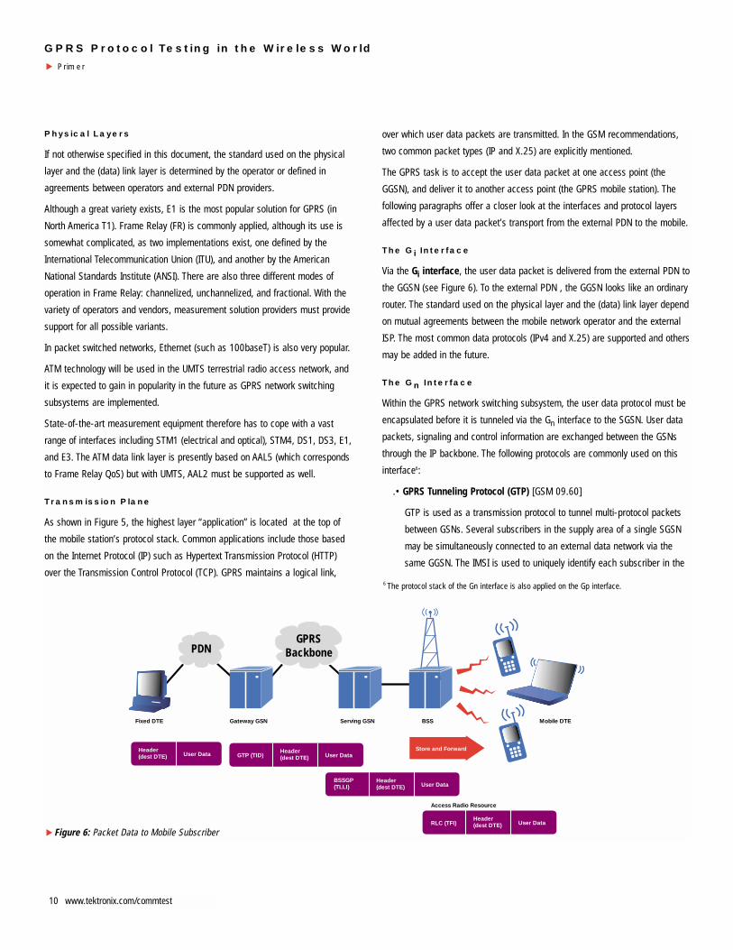
The GPRS task is to accept the user data packet at one access point (the
GGSN), and deliver it to another access point (the GPRS mobile station). The
following paragraphs offer a closer look at the interfaces and protocol layers
affected by a user data packet’s transport from the external PDN to the mobile.
The Gi Interface
Via the Gi interface, the user data packet is delivered from the external PDN to
the GGSN (see Figure 6). To the external PDN , the GGSN looks like an ordinary
router. The standard used on the physical layer and the (data) link layer depend
on mutual agreements between the mobile network operator and the external
ISP. The most common data protocols (IPv4 and X.25) are supported and others
may be added in the future.
The Gn Interface
Within the GPRS network switching subsystem, the user data protocol must be
encapsulated before it is tunneled via the Gn interface to the SGSN. User data
packets, signaling and control information are exchanged between the GSNs
through the IP backbone. The following protocols are commonly used on this
interface6:
.• GPRS Tunneling Protocol (GTP) [GSM 09.60]
GTP is used as a transmission protocol to tunnel multi-protocol packets
between GSNs. Several subscribers in the supply area of a single SGSN
may be simultaneously connected to an external data network via the
same GGSN. The IMSI is used to uniquely identify each subscriber in the
Store and Forward
Fixed DTE Gateway GSN Serving GSN BSS Mobile DTE
Header(dest DTE) User Data
PDNGPRS
Backbone
Header(dest DTE)GTP (TID) User Data
Header(dest DTE)
BSSGP(TLLI) User Data
Header(dest DTE)RLC (TFI)
Access Radio Resource
User Data
Figure 6: Packet Data to Mobile Subscriber
▲
6 The protocol stack of the Gn interface is also applied on the Gp interface.
GPRS Protocol Testing in the Wireless World
Primer▲
11www.tektronix.com/commtest
network switching subsystem.
A subscriber may also run several applications simultaneously; each of
them using different external PDNs connected to the same GGSN.
Therefore, each application must also be uniquely identified in the NSS.
The Network Service Access Point Identifier (NSAPI) is used for this
purpose. The NSAPI is assigned when the GPRS mobile station requests
a call setup, a process referred to as the Packet Data Protocol (PDP)
Context Activation Procedure. A PDP context describes the properties of a
link between the GPRS mobile station and the GGSN, such as which PDP
is transmitted via the link, which QoS level is used for the transmission,
the access point in use, etc.
The user identity (IMSI) and the application identifier (NSAPI) are
integrated into the Tunnel Identifier (TID)7 which uniquely identifies the
subscriber’s sublink between the GSNs. The TID is part of the GTP
header, which is added to the user data packet during the encapsulation
process in the GTP. The user data packet can then be easily tunneled to
the SGSN without further interpretation. This feature makes GPRS open to
future user data protocols.
• Internet Protocol (IP) [RFC 791], User Datagram Protocol (UDP) [RFC
768], Transfer Control Protocol (TCP) [RFC 793]
User data, signaling and control information are exchanged between the
GSNs and tunneled through the IP backbone in the form of GTP packets.
Either UDP or TCP are applied by the endpoints of the tunnels (SGSNs
and GGSNs), depending on the user data protocol. Each link on the
transmission path between the (external) Data Terminal Equipment (DTE)
and the mobile DTE is either reliable or unreliable. GPRS between the two
access points Gi and Um is just one link in the overall transmission of the
user’s data packet.
If IP is used as user data protocol, transmission between the external DTE
and the mobile DTE is unreliable. Therefore, the GPRS link between the
GSNs can also be unreliable and UDP can be applied on the “sublink”
over the NSS part.
If the user data protocol is X.25, reliability is ensured on each link and
must therefore also be guaranteed between the GSNs. In this case, the
reliable transport layer protocol TCP must be used.
On the Gn and Gp interfaces, the GPRS Tunneling Protocol (GTP) presents the
greatest challenge to measurement equipment; TCP/UDP/IP measurement
procedures are already well defined.
The Gb Interface
Most new protocol layers can be found on the Gb interface. As with all other
interfaces on the transmission plane, this interface is used to exchange both
user data and signaling information. This interface allows several users’
connections to be multiplexed over the same physical resources. Due to the
bursty nature of most packet switched applications, this is done based on the
users’ activity. (This is one major difference to the A interface, where the
physical resources are permanently allocated to one subscriber as long as a
circuit switched call is maintained.) The two highest layers (SNDCP and LLC)
are used for peer-to-peer communication between the SGSN and the GPRS
mobile station, while the lower layers are applied between the SGSN and the
BSS (PCU).
• SubNetwork Dependent Convergence Protocol (SNDCP) [GSM 04.65]
The SNDCP layer is located above the LLC layer in the SGSN and GPRS
mobile station. Its central task is to improve the channel efficiency. To do
so, the SNDCP layer compresses header information and user data using
separate algorithms to minimize the amount of information transmitted
over the air interface. To meet the lower LLC layer’s maximum frame
length restrictions, the SNDCP layer segments larger user data packets
and re-assembles these on the receiver’s end. The SNDCP layer can
also multiplex several “small” user data packets into a single LLC frame
and de-multiplex these on the receiving end. This layer is also
responsible for ensuring that user packet data is transmitted and
received according to the negotiated QoS level.
Network Service Access Points (NSAPI) are opened between the SNDCP
layer and the application layer above on the GPRS mobile station end to
transfer user packets to/from the respective application.
• Logical Link Control (LLC) [GSM 04.64]
The LLC layer is responsible for handling the virtual connection between
the SGSN and the GPRS mobile station and exists even when no physical
resources are available between the two. It supports peer-to-peer data
transfer between the SGSN and the GPRS mobile station. For each
Temporary Logical Link Identifier (TLLI) the LLC offers various services
using the Service Access Point Identifier (SAPI). These services may
include Quality of Service classes for user data, GMM/SM signaling
information and/or SMS data.
In addition to managing the logical link, the LLC layer ensures user data
confidentiality using ciphering/encryption features.
The transmission of LLC PDUs is possible in the acknowledged and
unacknowledged mode. In the acknowledged mode, each LLC PDU is
7 See GSM 03.60 Version 7.1.1 Release 98, chapter 14.5 TID

GPRS Protocol Testing in the Wireless World
Primer
▲
12 www.tektronix.com/commtest
confirmed by the receiver’s side. This is a service provided by SNDCP
request.
While LLC layer information is transmitted directly and transparently to the
mobile station via the BSS, the lower layers in the Gb interface protocol stack
are used between the BSS (PCU) and the SGSN for the transmission of LLC
PDUs.
On the GSM A interface, a physical resource is dedicated to a single subscriber
for the duration of a call, independent of information flow. On the Gb interface,
however, several subscribers can be multiplexed on a common physical
resource. Usage rates can vary between zero and the maximum possible data
rate. In addition to user data, signaling information can also be sent over the
common physical resource.
• Base Station System GPRS Protocol (BSSGP) [GSM 08.18]
The BSSGP provides radio-related, QoS, and routing information
between the MAC/RLC layer of the PCU and the SGSN. The BSSGP layer
also performs node management control functions between a remote
BSS (PCU) and the SGSN. The BSSGP layer provides a connectionless
link between the SGSN and BSS handles paging requests from the SGSN
to the BSS, and provides flow control between the SGSN and BSS, etc.
• Network Service (NS) [GSM 08.16]
The NS is responsible for the transmission and reception of higher layer
packets across the Gb interface. Load sharing is supported as well as
virtual connections (NS-VC) for peer-to-peer communication between
remote devices using NS. The NS is based on Frame Relay connections
between the SGSN and BSS (PCU). In the future, a variant using IP over
Ethernet is to be expected.
• L1bis [GSM 08.14]
Physical layer configurations and protocols can be applied as specified in
GSM 08.14: ANSI T1.403, X.21, V35, ITU G.703, and ITU G.704.
When the LLC packet arrives at the BSS (PCU), it is forwarded to the GPRS
mobile station. There the Radio Link Control is responsible for efficient use of
the physical link on the air interface and the MAC for handling access to the
physical link:
• Radio Link Control/ Medium Access Control (RLC/MAC) [GSM 04.60]
These sub-layers are responsible for packet switched radio resource
management. The RLC is responsible for segmentation and re-
assembly of the LLC packets. The segmentation results in RLC blocks.
Control information is added to each RLC block to allow Backward Error
Correction (BEC). The size of these segments is such that when applying
the coding schemes, they precisely fit on four normal bursts (= radio
block). With BEC, both acknowledge and unacknowledged mode are
possible.
The MAC layer handles procedures related to common transmission
resource management. The layer allows point-to-point transfer of
signaling and user data within a cell. As several subscribers can be
multiplexed on one physical channel, each connection has to be
(temporarily) uniquely identified. These connections are referred to as
Temporary Block Flows (TBF). A TBF is a physical connection between
the mobile station and the PCU. The TBF is unidirectional; uplink and
downlink resources are separated in the block flow – this allows for
asymmetric allocation of uplink and downlink resources. The TBF is
maintained only for the duration of the data transfer. During the flow, one
or several LLC PDUs are (successfully) transmitted. The TBF is identified
by a Temporary Flow Identifier (TFI). The TFI is added to the RLC block.
The medium access can be realized by fixed, dynamic, and extended
dynamic allocation. While the TFI is sufficient for fixed allocation, the
Uplink State Flag (USF) must be used downlink for dynamic medium
access. Up to 8 subscribers can dynamically share one physical channel,
but which of them is allowed to temporarily use next the uplink resources
must be indicated on the downlink channel.
• GSM RF
This layer is based on the GSM 05 specification, which describes the
physical characteristics of the air interface.
The Abis interface
While The RLC/MAC layer is implemented in the PCU, the GSM RF layer is
located in the Base Transceiver Station. The PCU is normally located at the
Base Station Controller or SGSN site. Some aspects of the Abis interface –
which connects the BTS and the BSC – are relevant here:
• Abis interface [GSM 08.60]
When the PCU is remote to the BTS, fixed-length frames of 320 bits (20
ms) are transferred from the BSC to the BTS. In GSM, they are referred to
as TRAU frames; in GPRS they are called PCU Frames. The PCU frames
hold both GPRS data and GPRS RLC/MAC associated control information.
Depending on the vendor, the BTS (including the CCU) may control some
functions of the PCU (in the BSC), but the PCU also may control some
functions of the remote CCU. Remote control information is carried
inband in the PCU frames. Tektronix offers customized measurement
solutions for these environments.
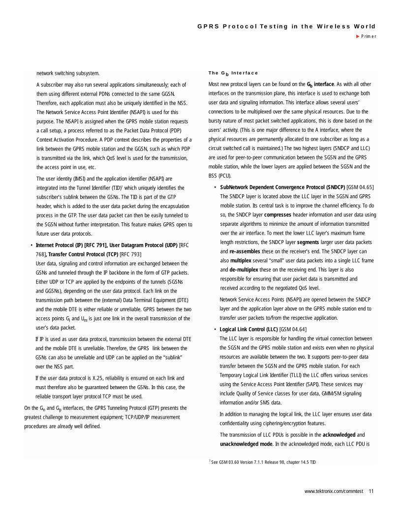
Signaling Plane
The signaling plane provides supplementary services8 and supports
transmission plane functions by controlling:
• GPRS network access connections
• attributes of established network connections
• routing paths to support user mobility
• assignment of network resources to meet changing user demands
The following paragraphs offer a closer look at the interfaces and protocol
layers that comprise the GPRS signaling plane.
The GPRS Tunneling Protocol (GTP) on the Gn and Gp interfaces is not only
used to transmit user information on the transmission plane but also carries
information on the signaling plane, for example the “Create PDP Context
Request” of the PDP Context Activation Procedure.
In GSM networks, Mobility Management (MM) and Connection Management
(CM) are realized between the VMSC/VLR and the mobile station in peer-to-
peer communication. The Base Station Subsystem is only used as a relay. The
same is true for the GPRS mobility management, which is located above the
LLC, and where separate Service Access Points are used to address this
management protocol layer:
• GPRS Mobility Management/Session Management (GMM/SM)
Mobility Management and PDP Context Activation, Modification, and
Deactivation Function are implemented. In the PDP Context Activation
process, for example, the mobile station requests a packet data protocol,
QoS level. (see Figure 7)
The remaining signaling planes are based on the SS7 protocol stack. SS7 is
used for signaling on the Gr, Gc, Gf, and Gd interfaces between SGSN and HLR,
GGSN and HLR, SGSN and EIR, and SGSN and SMS-GMSC/SMS-IWMSC.
• Mobile Application Part (MAP)
This protocol layer was already applied in GSM to realize mobile-specific
signaling between exchanges and databases (HLR, VLR, etc.) It is
enhanced to include GPRS-specific functions.
• Transaction Capabilities Application Part (TCAP)
The TCAP supports MAP and is used as a dialog handler between the
databases. (HLR, VLR, etc.)
• Signaling Connection Control Part (SCCP)
SCCP is an SS7 protocol. It offers connectionless and connection
oriented services for switches and databases. It is used to address
switches in the worldwide SS7 network (Global Title Translation, GTT)
• Message Transfer Protocol (MTP)
MTP covers the SS7 signaling on layer 1 to 3. It is responsible for
managing signaling links, signaling routes, and signaling traffic.
The Gs interface is the only signaling plane interface not based on the MAP. It
is used for common GSM/GPRS procedures such as location updates. Above
Store and Forward
Fixed DTEGateway GSNServing GSNBSSMobile DTE
Header(dest DTE)User Data
PDNGPRS
Backbone
Header(dest DTE) GTP (TID)User Data
Header(dest DTE)
BSSGP(TLLI)User Data
Header(dest DTE) RLC (TFI)
Access Radio Resource
User Data
Figure 7: Packet Data from Mobile Subscriber
▲
8 Source: GSM 02.60, Version 6.1.1, Release 1997, p. 23.
13www.tektronix.com/commtest
GPRS Protocol Testing in the Wireless World
Primer▲

the SCCP and MTP there is the
• Base Station System Application
Part + (BSSAP+) [GSM 09.18,
GSM 03.60] The BSSAP+ is a
subset of the A interface’s BSSAP,
used for common GSM/GPRS
procedures including Mobility
Management.
Measurement Issues
Monitoring and PerformanceMeasurement
The main reason for operators and
manufacturers to collect data is to
retrieve the necessary information to
assist in decision making in order to
reach a specified objective. Data
collection and recording can be part of
the mobile network performance
evaluation. In this case, data is collected
from each network element (NE)
according to a schedule established by
the Operations System (OS). Performance
measurement can also be performed on
individual network elements by the
manufacturer and/or operator to
determine the limitations of the NE before
introducing it into an existing network.
The major objectives for data collection
are:
• to receive an overall view about the
actual performance level of an
item. An item can be a NE, a part of
a network, the PLMN, or the OS.
This information is used to decide
which measures need to be taken in
Figure 9: Signaling Planes between SGSN and Mobile Station
MS Um SGSN
Relay
Gb
IP/X.25
RLC
MACMedium Access
Control
RLCRadio Link
Control
LLCLogical Link
Control
GMM/SMGPRS MobilityManagementand SessionManagement
GSMRF
NS/FR
BSSGPBSS GPRSProtocol
LLCLogical Link
Control
GMM/SMGPRS MobilityManagementand SessionManagement
L1Physical Layer
MAC
GSMRF
BSSGP
NS/FR
L1
• GPRS attach/detach• Security• Routing area update, location update• PDF context activation, modification and deactivation
• Logical connection• Acknowledge/unacknowledged peer-to-peer operation• Ciphering• SAPs to higher layer (SNDCP, GMM/SM, SMS)
SGSN HLR, EIR, SMS-GMSC
HLRGGSN
Gr,f,dGc
MSC/VLRSGSN
Gs
MTP L2
MTP L3
SCCPSignaling
ConnectionControl Part
TCAPTransactionCapabilities
Application Part
MAPMobile
ApplicationPart
SCCP
TCAP
MAPMobile
ApplicationPart
SCCP
BSSAP+
L1
MTP L2
MTP L3
L1
MTP L2
MTP L3
L1
SCCP
BSSAP+BSS
ApplicationPart+
• GPRS-specific MAP extension • Add-on to BSSAP functionalities
MTP L2
MTP L3
L1
Figure 9: GPRS Signaling Planes
▲
Figure 8: Signaling Planes between SGSN and Mobile Station
▲
GPRS Protocol Testing in the Wireless World
Primer
▲
14 www.tektronix.com/commtest

the planning process, the operation and maintenance field, training of
employees, etc.
• to determine a possible need for an improvement of the item. This can
affect both installed items already in operation and items under
development.
• to discover the differences in the specified/predicted characteristics of
the item and its field characteristics.
• to improve forecasts on the item’s behavior and problems.
Tektronix GPRS equipment is especially suited for GPRS interface testing.
Monitoring can be performed with both the K1205, a pure monitoring device,
and the K1297, which is used also for simulation and emulation. With Tektronix
measurement equipment, two main ways to present results are available:
• statistics method: counts the occurences of specific events such as
overload situations, failures, tracing, etc.
• online data analysis: received data can be filtered to focus on particular
aspects of communication. (Show all TCP user data larger than 140
octets, for example.)
Emulation and Simulation
Simulation is the representation or imitation of one process or system through
the use of another. In a test environment, a simulator can be used to substitute
a network element up to a particular part of the network. For instance, when
testing an SGSN, the BSS behavior can be simulated by test equipment.
Major applications for simulators include:
• Collecting information about a network element’s dependability. Within the
simulation, certain normal and abnormal situations can be created, and
the NE’s ability to cope with the simulated environment offers the
operator and manufacturer an approximation of the unit’s field
characteristics. Simulations are also often used for conformance testing.
• Substitution for missing NEs or parts of a network during the
development process of an entity. The simulation helps to approximate
the item’s ability to perform in a real life environment.
• Cost savings for the development of an entity. The strong and weak
points of an entity can be identified early in the development process or
before introducing it into a running network.
The term Emulation is often used in computer science when a device is
imitated with the help of another (such as terminal emulation). For Tektronix,
emulation represents a higher form of simulation. Here, the behavior of certain
communication protocol layers is simulated automatically and in conformance
with the protocols. The targets set for the emulation are usually similar to those
of the simulation.
The Gn Interface
With GPRS, monitoring becomes an essential and
demanding task because of the complex
behavior in the multiple interfaces between
the GPRS and GSM NEs and on the GPRS
backbone. The goal is the rapid identification
of problems, malfunctions, reactions, and
performance issues. The Gn (Gp) interface is a
good example of the new measurement aspects in
GPRS.
The GPRS Tunneling Protocol (GTP) is implemented
on the Gn interface to allow multi-protocol packets
to be tunneled between the GSNs. The Internet
Protocol stack (network layer and transport layer) is
used to transmit the GTP packets between the GSNs. The data link layer and
physical layer depend on the operator’s network configuration. When testing
the Gn (Gp) interface, the features and functionality of the new GTP layer must
be verified. With the IP transmission technology, new statistical data is
necessary. In GSM networks, measured values may have included the number
of pages per location area per hour, busy hour call attempts (BHCA) per BSC
and/or MSC, handovers per BSC per hour, etc. The GPRS network, however,
transmits user data packets. Therefore, the concept of BHCAs or Erlang is no
longer applicable. Concepts to monitor and judge this kind of traffic must be
adopted from the packet switched environment.
Using the Gn, Gp and Gi interfaces as an example, the following list offers an
impression of the new and modified aspects related to monitoring, simulation,
performance measurement and packet transfer:
• Monitoring and statistics:
One new statistical “parameter” is the mean packet delay: in the SGSN,
GGSN, and PCU network elements, packets are processed and
encapsulation and de-capsulation, header modification and address
translation takes place. In case of short-term congestion, packets can be
buffered. The mean packet delay depends both on the processing power
of the NE and on the subscribers’ overall traffic behavior. These two
factors determine the field characteristics of the NE. Given the mean
UDPUser
DatagramProtocol
TCPTransmission
Control Protocol
GTPGPRS
TunnellingProtocol
IPInternet Protocol
L2Link Layer
L1Physical Layer
15www.tektronix.com/commtest
GPRS Protocol Testing in the Wireless World
Primer▲

GPRS Protocol Testing in the Wireless World
Primer
▲
16 www.tektronix.com/commtest
packet delay at each network element, the overall mean delay between
the operator’s access points can be determined.
If the operator’s network offers the QoS “Delay class 1”, the operator
must guarantee that the mean transfer delay between the two network
access points is less than 0.5 seconds for Service Data Units of 128
octets. 95% of the SDUs must be transmitted in less than 1.5 seconds.
Other GPRS QoS classes to be considered include reliability classes and
throughput classes.
Note: the limiting factor is normally not the transfer rate in kilobytes per
second, but rather the amount of packets which can be processed and
switched by a NE in one second.
Other new statistical values include kilobytes per second, mean packet
size, kilobytes per user, etc. There is a long list of statistics which can be
compiled from packet switched networks. Both the K1205 and K1297
can provide these statistics.
• Simulation
For GPRS, it is expected that a certain number of subscribers wants to
download information from the Internet and/or their company’s Intranet.
For this group, the traffic behavior can be determined in advance: the
average size of the files to be downloaded, the number of IP packets
required to transmit files of this size; delay between packets, etc. Here
“bursty” behavior can often be detected: several packets are sent very
quickly one after the other, then there is a longer break before the next
group of packets is transmitted. Given several subscriber traffic profiles,
manufacturers and operators can use test equipment to simulate this
traffic behavior to gain an impression of the network element’s field
characteristics.
In simulation, the K1297 Protocol Tester represents one or several
communication partners – in a protocol-conformant or an error
simulation mode. All protocol layers from layer 2 can be set according to
the OSI reference model. Test scripts can be created in the form of state
machines using the test manager and run dynamically. The integrated
Message Building System is a tool for creating messages interactively.
Generated messages can also be dynamically modified during run time.
Messages and message frames can be stored in a pool.
• Packet Transfer and TCP timing problems
Subscriber mobility can cause problems with TCP connections. TCP
connections are normally optimized during the transmission of data (for
example, timer settings for retransmission of IP packets are optimized). If
a GPRS mobile station moves from a cell where a data transmission rate
of 100 kbps was possible to another cell where a data transmission rate
of only 10 kbps is possible, the TCP timer will expire for packets which
have not yet been transmitted over the air interface. This leads to an

excessive amount of retransmitted TCP/IP packets.
• Interworking between GSNs and the packet switched backbone
The interworking of GSNs with the GPRS IP based backbone must be
tested to verify correct packet routing and addressing. Access to the
DNS Server must also be verified. The DNS Server is responsible for
mapping logical names to IP addresses. When provided with a logical
name for an external packet data network (such as the Internet) the
SGSN can retrieve the closest GGSN and its IP address from the DNS
Server.
The Gi Interface
The Gi interface specifies how the mobile
network (GGSN) is connected to external
packet data networks. The physical layer and
data link layer are subject to agreements
between the operator and the ISPs. On the
network layer, interworking with IP and X.25
is specified. On the Gi interface, test
equipment must be able to cope with various
transmission solutions such as STM1, ATM, or Ethernet. The demands placed
on test equipment on this interface are similar to those on the Gn interface for
layer 1 to 3.
The Gb Interface
Most new GPRS protocol layers can be found on the Gb interface.
On the transmission plane, the two highest protocol layers are the
Subnetwork Dependent Convergence Protocol (SNDCP) layer and
the Logical Link Control (LLC) layer. The peer entities of the two
layers are the SGSN and the GPRS mobile station. The LLC is
responsible for handling the logical link between the peer entities,
independent of the physical resources allocated between them.
The SNDCP is responsible for processing user data (compression,
segmentation, and multiplexing). The Base Station System GPRS
Protocol (BSSGP) and Network Service (NS) layers are used
between the SGSN and the BSS (PCU). The BSSGP provides radio-
related, QoS, and routing information between the SGSN and PCU
(for MAC/RLC). The NS is used to establish a virtual connection
between the SGSN and PCU. The NS layer performs load
balancing, multiplexing, and bandwidth allocation tasks. The layer
1 technology can be selected from the GSM Rec. 08.14.E1, ANSI
T1.403 and X.21 are two of the
possible physical layer
technologies.
On the signaling plane, the Gb
interface offers GPRS Mobility
Management (GMM) and Session
Management (SM). The GMM/SM
is located in part on the LLC, in
part on the BSSGP. The SMS
Service is implemented directly
above the LLC.
Monitoring, performance testing,
simulation and emulation and
conformance testing of all new
protocol layers are demands on
testing equipment. The following
examples show test applications
on the Gb interface:
1. In Figure 10 BSP1, the K1297 emulates and simulates the GPRS core
network solution (SGSN, GGSN, and register). The BSS is attached to the
K1297. The Implementations Under Test are both the BSS and the mobile
stations (MS). The K1297 itself consists of three major components:
• The Primary Rate Interface Monitoring Emulation (PRIME) provides the
E1 interface to the BSS and Gb traffic is routed via this connection. The
L2’Link Layer
L1’Physical
Layer
IP / X.25
IP
SNDCPSubNetworkDependent
ConvergenceProtocol
BSSGPBSS
GPRSProtocol
FRFrames Relay
L1Physical Layer
GMM/SMGPRS MobilityManagement
and Session
Management
LLCLogical Link
Control
SMS
Figure 11: BSP1
PRIME(Emulation)
ApplicationProcessor AP
(Control)
PC-board(NDIS)
K1297BSS
MS
MS
E1
e.g.fractionalFrameRelay Ethernet
board
IP-user data
RSS
IPnetwork
Figure 10: BSP1
▲
17www.tektronix.com/commtest
GPRS Protocol Testing in the Wireless World
Primer▲

GPRS Protocol Testing in the Wireless World
Primer
▲
18 www.tektronix.com/commtest
SGSN protocol stack facing the Gb interface is emulated on the PRIME
board. This enables rapid processing of both incoming and outgoing data
via this interface.
• The Application Processor (AP) controls the PC and PRIME boards. This
component is responsible for directing the emulation, simulation scripts,
monitor applications, and the ARP proxy.
• The Ethernet interface provides a means to connect the K1297 to an
external packet data network. This is necessary if the K1297 is to
emulate and simulate the Network Switching Subsystem’s packet
switched domain. The Ethernet interface is handled by the PC board, on
which an NDIS driver is installed.
(The external PDN or any IP client application can also be realized on the
PC board itself. In this case, the NDIS driver emulates an Ethernet board
to provide access from the PC side to all emulation stacks on the PRIME
with IP on top. This feature may be used to simulate mobiles running PC
applications connected to an SGSN via a BSS. When a connection is
successfully established between the K1297 and the BSS, the IP data –
user data – is directly transferred between the PRIME and the PC boards.)
To realize an Attach Request with a fixed IP address (of the GPRS mobile
station), proceed as follows: First, a default state for the signaling connection
and one point-to-point connection must be defined. The next step is to realize
the GPRS attach itself, which includes the BSSGP flow control and
acknowledgement, and the realization of the Attach Request message on the
GMM/SM layer. When finally the Attach Complete message is sent to the
mobile station, the attach was successful. To carry out this process, the K1297
user applies predefined messages in the K1297 in combination with specific
values entered via changes in scripts, entries in tables, and by selecting menu
options. Following the attach, the PDP context activation process begins with
the PDP context request. If the subscriber uses a dynamic IP address, the IP
address for this connection is generated by the K1297. (This is a GGSN task.)
Furthermore, the QoS, Radio Status, etc. is determined given the entries in the
tables, menus, etc. When the PDP Context Activation is accepted, data can be
downloaded from a Web server.
2. Another common application of the K1297 and K1205 is passive
monitoring. With the K1205, up to 4 bi-directional channels can be
monitored by each board. After selecting the physical channel and the
Frame Relay mode, the K1205 user can apply filtering options to retrieve
specific information including the elements belonging to a GMM/SM attach
request, IP packets of a specific size, etc. This information is stored in a log
file. In the monitor application, additional filters can be used to select
information for presentation, such as statistics and counters.
3. Conformance testing on the Gb interface is also possible with the Tektronix
K1297. This is described separately in the last section of this chapter (see
page 29).
The Gr, Gf, Gc, and Gd Interfaces
The interfaces carrying SS7 signaling information also require enhancements
for GPRS operation. The highest layer Mobile Application Part (MAP) must be
enlarged to support transmission of new GPRS subscriber profiles. The
remaining layers - MTP, SCCP, and TCAP - require no modification, as they
perform the same tasks as in GSM.
For the MTP, SCCP, and TCAP layers, the monitoring,
performance testing, simulation and emulation tools can
be adopted from GSM. This is partially true for the MAP,
as well. Yet a special focus lies on the functionality and
dependability of the MAP, and GPRS-specific monitoring,
emulation and/or simulation routines can be of help here:
An SDL style test manager, integrated in the monitor
functionality of the K1297, allows the system to react
directly to certain events with user-defined actions. For
example, statistical values are obtained by increasing a
counter when certain SS7 IAM (Initial Address Messages)
are received. Active monitoring is also possible and
useful, for example, if a parallel connection between the
measuring device and the transmission lines cannot be
established.
The Gs Interface
An optional interface between the SGSN and VMSC/VLR
is specified for common procedures like combined LA
and RA updates. This interface implements a reduced
version of the GSM A interface for the signaling plane. On
the highest layer, the Base Station System Application Part
+ (BSSAP+) is realized. The remaining layers are
adopted from the A interface: SCCP and MTP.
Hence, for monitoring, performance testing, emulation,
and simulation, the test equipment can be “easily”
adapted to the Gs interface. A special focus is placed on
the BSSAP+ layer.
MTP L2
L1
MAPMobile
ApplicationPart
TCAPTransactionCapabilities
Application Part
SCCPSignaling
ConnectionControl Part
MTP L3
MTP L2
L1
SCCP
MTP L3
BSSAP+BSS
ApplicationPart+

Summary
Monitoring, performance testing, simulation, and emulation are crucial steps
in the process of verifying the functionality and efficiency of individual
network elements or the operator’s entire network. With the K1297,
Tektronix offers a protocol tester and software to support these tasks.
During the installation process, the user of the Tektronix K1297 can set up
the tester’s operating mode. When setting up the K1297, the user
determines [1] whether to test the SS7 signaling plane (starting with the
MTP protocol) or the GPRS interfaces (beginning with Frame Relay).
With the decision for SS7, both the Gr "MAP" interfaces and the Gs
(BSSAP+) interface can be tested.
When GPRS interfaces are tested, the DLCI value of the Frame Relay header
indicates whether complete Frame Relay data is present [see 2, DLCI=0], or
if the information is a full GPRS stack (Gb interface). If RFC1490 PDUs are
found, the corresponding user part is selected (Gi and Gn interfaces).
In case of the Gb interface, for the emulation of the LLC and higher layers,
the LLC SAPI (Service Access Point Identifier) [see 3] determines whether
user data or short messages should be transmitted (SNDCP, SMS) or
Mobility Management (GMM/SM) will be handled.
On the Ethernet interface, the lower layers are replaced by Ethernet and MAC
(Media Access Control). Above the MAC layer, a complete IP stack is found.
With these options, the Tektronix K1297 covers the full range of GPRS interface
testing.
Conformance Testing [ETSI ETR 021]
The principal idea of standards is to allow the development of systems by
different manufactures which can interoperate with each other. Conformance
testing is the verification process in which an independent body determines if
a system, piece of equipment or implementation satisfies the criteria of a
particular standard. “During the test phase, the implementation is referred to
as the Implementation Under Test (IUT).”9
The conformance assessment process specifies test methods to ensure the
comparability of test results generated by different test laboratories. This
process can be divided into three steps:
1. Test Preparation: the client (manufacturer) and the test laboratory agree
on the test and the how to conduct it (including testing method and tested
protocols). Here there are two important documents:
• Protocol Information Conformance Statement (PICS): describes the
capabilities and the used options of the client’s IUT. It also states which
features have been omitted.
• Protocol Implementation eXtra Information for Testing (PIXIT): holds
additional information about the IUT important for the test laboratory, such as
addressing information, complements for the range of values stated in the
PICS.
2. Test Operation: During this step, the tests are carried out. Normally a
collection of executable tests are available, called Executable Test Suites (ETS).
These are based on an abstract description of the tests, the so-called
(standard) Abstract Test Suite (ATS).
3. Conformance Test Reports: Finally, the conformance test results must be
made available. The Protocol Conformance Test Report (PCTR) holds the
conformance test results for a single protocol layer including all necessary
information (PICS, PIXIT, IUT). The System Conformance Test Report (SCTR)
summarizes the conformance test results, identifying the participants (such as
test laboratory, client, SUT) and a system report summary with a reference to
the different standard components (such as protocols, PICS).
Simulation and Conformance Testing Example: BlockProcedure NS
There are two new layers which enable peer-to-peer communication between
the SGSN and the GPRS mobile station, the Subnetwork Dependent
9 ETSI ETR 021: September 1991, p. 8
IP
GTP
UDP
RADIUS
ICMP
SNDCP GMM/SM SMS
LLC MAP DTAP
BSSGP
NS
FR
TCAP BMAP
SCCP
MTP
BSSAP+
RFC 1490
IP
MAC
Ethernet PRI
1
2
3
19www.tektronix.com/commtest
GPRS Protocol Testing in the Wireless World
Primer▲

GPRS Protocol Testing in the Wireless World
Primer
▲
20 www.tektronix.com/commtest
Convergence Protocol (SNDCP) layer and the Logical Link Control (LLC) layer.
The Base Station System GPRS Protocol (BSSGP) and the Network Service (NS)
are used between the BSS and SGSN.
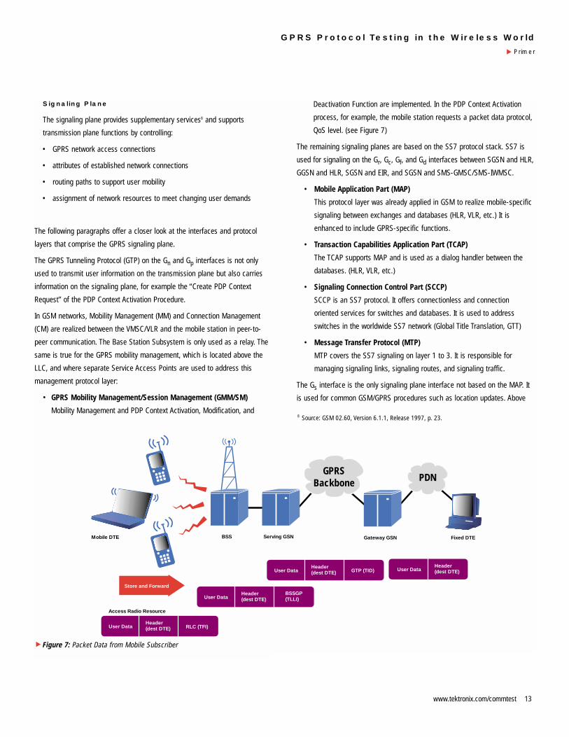
Figure 11 shows a conformance test scenario for the NS layer. The “Remote
Single Layer” testing method is applied (only functions and tasks are tested
here, independent of lower and higher layers). For conformance testing, a set
of Abstract Test Suites (ATS) is defined. Several refer to a specific event of the
Network Service Virtual Connection (NS-VC) management: a blocking procedure
is used by the NS entity to inform its NS peer entity when an NS-VC becomes
unavailable for the NS user traffic (see Figure 11). The NS-VC management is
part of the Network Service Control entity, which is also responsible for NS SDU
transmission and load sharing.
User data traffic is transmitted on several virtual connections of one NS-VC
group between the BSS and the SGSN. NS-VCs between the same peer entities
are arranged in one NS-VC group. NS-VC grouping therefore has only local
significance between the BSS and SGSN.
• In Figure 11, the user data is transmitted on virtual connections 1
through 4.
• The BSS side then blocks the virtual connection VC1. The NS block
packet contains the Virtual Connection Identifier (VCI, here 1) and a cause
element, which indicates the reason for blocking the virtual connection.
The most common reasons for blocking a virtual connection are transit
network failure, O&M intervention, and equipment failure. The VC block
packet may be sent on any alive (= blocked or unblocked) NS-VC that
belongs to the same NS-VC group.10 When blocking the VC 1, the BSS
must be capable of redistributing the user data traffic (NS-UNITDATA
PDUs11) on other virtual connections of the same NS-VC group.
• When blocking the VC 1, there can still be unitdata PDUs on the VC 1
from the SGSN to the BSS. Therefore, the BSS must still accept incoming
user data traffic on VC 1. This happens either until the BSS side gets an
Send in any alive(blocked or unblocked)
VC of the relevant group.
Send in any alive(blocked or unblocked)
VC of the relevant group.
Re-distribution of UDTson other VCs of the
same VC-group.
Cause:Transit network failure,O&M intervention,Equipment failure
BSS
BSSTns
Tns
SGSN
SGSN
UDT (VC 2)
UDT (VC 3)
UDT (VC 4)
UDT (VC 1)
UDT (VC 1)
UDT (VC 1)
UDT (VC 2)
UDT (VC 3)
NS_BLOCK [VC 1=1, Cause]
NS_BLOCK_ACK [VC 1 = 1]
VC 1 = blocked
VC 1 markedas blocked
VC 1 remains in block untilUNBLOCK is received.
STOP Tns-block
Timer Tns-block(3s) is started.
Re-distribution of UDTson other VCs of the
same VC-group.
UDTs (VC 1) are stillaccepted untilreceived ACK.
... shall stop toaccept NS-UNITDATAPDUs, if the number
of retries of theblocking procedures
is exceeded.
Figure 11: Block Procedure NS
▲
10 Some cases may require different handling.
11 By the means of the NS-UNITDATA PDU, NS SDUs are transmitted in an unacknowledged
mode via the Gb interface.
NS block acknowledge packet, or until the number of retries specified for
the blocking procedure is exceeded. Then the TNS block timer stops.
• After sending the NS block acknowledge packet, the SGSN must
distribute the user data traffic on the unblocked virtual connections.
Two possible conformance tests will be shortly portrayed. The conformance test
of one entity can be realized via simulation: the BSS side or the SGSN can be
simulated by a system simulator. If the SGSN is simulated, there are two
possible test configurations shown in Figure 12: Test Configurations I & II:
• A test configuration for testing the Network Service Protocol and the
BSSGP part where no GPRS mobile station is needed. The IUT is the BSS.
• A configuration for testing the BSSGP where the GPRS mobile station is
needed. If the full implementation of the Gb interface has to be tested,
then the LLC and SNDCP can also be examined. (The LLC and SNDCP
can be partially tested by directly attaching the MS higher layers to a
system simulator.)
So a system/network element simulator can be used for conformance test of
one interface’s entity.
Given the NS blocking procedure, the following two confirmation tests can be
performed:
• Normal sequence of events when IUT receives an NS block acknowledge
packet12:
When the IUT (BSS) receives an NS block acknowledge packet as a
response to the O&M initiated NS block in the “NS-VC unblocked” state
(the NS block acknowledge is received on another NS-VC belonging to
the same group), the IUT should stop the blocking procedure and remain
in the “NS-VC blocked & alive” state.
• Abnormal sequence of events when IUT receives an NS block
acknowledge packet 13:
When the IUT receives an unexpected NS block acknowledge packet for
an NS-VC which is locally blocked (in the “NS-VC blocked & alive” state),
the IUT should discard it and remain in “NS-VC blocked & alive” state.
The test case only passes if the IUT acts as specified in the Abstract Test
Suites.
Cell 1
Cell 2
(BSS)
Link 1
IUT: BSS+MS
Sim
ulat
ed
K1297/SGSN
Link 2
Cell 1
Cell 2
(BSS)
Link 1
IUT: BSS K1297/SGSN
Link 2
12 Tektronix, Protocol Tester: K1297, Conformance Tests for GPRS, C73000-M6076-C757-1,
Test case description NS_B_N_003
13 Tektronix, Protocol Tester: K1297, Conformance Tests for GPRS, C73000-M6076-C757-1,
Test case description NS_B_E_003
Figure 12: Test Configurations I & II
▲
21www.tektronix.com/commtest
GPRS Protocol Testing in the Wireless World
Primer▲

Glossary
Specifications:
ITU Recommendation E.880: “Field data collection and evaluation on the
performance of equipment, network, and services.”
ITU Recommendation G.704 (Blue Book): Synchronous frame structures
used at 1544, 6312, 2048, 8488 and 44 737 kbit/s hierarchical levels.
ETSI ETR 021: “Advanced Testing Methods (ATM); Tutorial on protocol
conformance testing (Especially OSI standards and profiles) (ETR/ATM-
1002)
GSM 04.08: “Digital cellular telecommunications system (Phase 2+); Mobile
radio interface layer 3 specification”.
GSM 04.60: “Digital cellular telecommunications system (Phase 2+); General
Packet Radio Service (GPRS); Mobile Station (MS) - Base Station System
(BSS) interface; Radio Link Control / Medium Access Control (RLC/MAC)
protocol”.
GSM 04.64: “Digital cellular telecommunications system (Phase 2+); General
Packet Radio Service (GPRS); Logical Link Control (LLC)”.
GSM 04.65: “Digital cellular telecommunications system (Phase 2+); General
Packet Radio Service (GPRS); Subnetwork Dependent Convergence
Protocol (SNDCP)”.
GSM 07.60: “Digital cellular telecommunications system (Phase 2+); General
Packet Radio Service (GPRS); Mobile Station (MS) supporting GPRS”.
GSM 08.14: “Digital cellular telecommunications system (Phase 2+); General
Packet Radio Service (GPRS); Base Station System (BSS) - Serving GPRS
Support Node (SGSN) interface; Gb interface layer 1”.
GSM 08.16: “Digital cellular telecommunications system (Phase 2+); General
Packet Radio Service (GPRS); Base Station System (BSS) - Serving GPRS
Support Node (SGSN) interface; Network Service”.
GSM 08.18: “Digital cellular telecommunications system (Phase 2+); General
Packet Radio Service (GPRS); Base Station System (BSS) - Serving GPRS
Support Node (SGSN); BSS GPRS Protocol (BSSGP)”.
GSM 09.02: “Digital cellular telecommunications system (Phase 2+); Mobile
Application Part (MAP) specification”.
GSM 09.16: “Digital cellular telecommunications system (Phase 2+); General
Packet Radio Service (GPRS); Serving GPRS Support Node (SGSN) -
Visitors Location Register (VLR); Gs interface network service
specification”.
GSM 09.18: “Digital cellular telecommunications system (Phase 2+); General
Packet Radio Service (GPRS); Serving GPRS Support Node (SGSN) -
Visitors Location Register (VLR); Gs interface layer 3 specification”.
GSM 09.60: “Digital cellular telecommunications system (Phase 2+); General
Packet Radio Service (GPRS); GPRS Tunneling Protocol (GTP) across the
Gn and Gp interface”.
GSM 09.61: “Digital cellular telecommunications system (Phase 2+); General
requirements on interworking between the Public Land Mobile Network
(PLMN) supporting General Packet Radio Service (GPRS) and Packet
Data Networks (PDN)”.
GSM 12.04: “Digital cellular telecommunication system (Phase 2); Performance
data measurements”.
GPRS Protocol Testing in the Wireless World
Primer
▲
22 www.tektronix.com/commtest

Index
A interface between BSS and GSM-NSS
AAL ATM Adaptation Layer
Abis interface between BTS and BSC
AC Authentication Center
AMPS Advanced/American Mobile Phone Service
ANSI American National Standards Institute
ATM Asynchronous Transfer Mode
ATS Abstract Test Suite
AuC Authentication Center
BEC Backward Error Correction
BHCA Busy Hour Call Attempt(s)
BSC Base Station Controller
BSS Base Station Subsystem
BSSGP Base Station Subsystem GPRS Protocol
BTS Base Transceiver Station
CAMEL Customized Application for Mobile Enhanced Logic
CCS7 Common control signaling system No 7 (SS7)
CCU Channel Codec Unit
CM Connection Management
CN Core Network
CS Circuit Switched
CT Conformance Test
DL Downlink
DLCI Direct Link Connection Identifier
DNS Domain Name Server
DTE Data Terminal Equipment
E1 2.048 kbps
EDGE Enhanced Data Rates for GSM Evolution
EIR Equipment Identity Register
EFR Enhanced Full Rate
ETR ETSI Technical Report
ETS Executable Test Suite
ETSI European Telecommunication Standards Institute
FR Frame Relay
Gb interface between BSS and SGSN
Gc interface between GGSN and HLR
Gd interface between SGSN and GMSC
Gi interface between GGSN and external PDN
Gf interface between SGSN and EIR
GGSN Gateway GPRS Support Node
GMM GPRS Mobility Management
GMSC Gateway MSC
Gn interface between SGSN and GGSN
Gp interface between SGSN and GGSN of external PLMN
GPRS General Packet Radio Service
Gr interface between SGSN and HLR
Gs interface between SGSN and VMSC/VLR
GSM Global System for Mobile Communications
GSN GPRS Support Node
GTP GPRS Tunneling Protocol
GTT Global Title Translation
HLR Home Location Register
HR Half Rate
HSCSD High Speed Circuit Switched Data
HTTP Hypertext Transmission Protocol
IMT-2000 International Mobile Telephony 2000
IP Internet Protocol
ISP Internet Service Provider
ITU International Telecommunication Union
IUT Implementation Under Test
kbps kilobits per second
LLC Logical Link Control
MAC Medium Access Control
MAP Mobile Application Part
MM Mobility Management
MS Mobile Station
MSC Mobile Switching Center
23www.tektronix.com/commtest
GPRS Protocol Testing in the Wireless World
Primer▲
MTC Mobile Terminating Call
MTP Message Transfer Part
NE Network Element
NMT Nordic Mobile Telephony
NS-VC Network Service - Virtual Connection
NSS Network Switching Subsystem
OS Operations System
OSS Operation Subsystem
PCU Packet Control Unit
PDN Public Data Network
PDP Packet Data Protocol
PDU Protocol Data Unit
PICS Protocol Implementation Conformance Statement
PIXIT Protocol Implementation eXtra Information for Testing
PLMN Public Land Mobile Network
QoS Quality of Service
RLC Radio Link Control
RFC Request for Comment
SAP Service Access Point
SAPI Service Access Point Identifier
SCCP Signaling Connection Control Part
SDU Service Data Unit
SGSN Serving GPRS Support Node
SM Session Management
SMS Short Message Service
SNDCP Subnetwork Dependent Convergence Protocol
SS7 Signaling System Number 7
SUT System Under Test
TBF Temporary Block Flow
TBI Temporary Block Identifier
T1 1544 kbps
TACS Total Access Communication System
TCP Transmission Control Protocol
TCAP Transaction Capabilities Application Part
TID Tunnel Identifier
TRAU Transcoder and Rate Adaptor Unit
TRX Transceiver
UDP User Datagram Protocol
Um air interface
UMTS Universal Mobile Telecommunication Service
UP Uplink
USF Uplink State Flag
UTRAN UMTS Terrestrial Radio Access Network
VC Virtual Connection
VLR Visitor Location Register
VMSC Visited MSC
W-CDMA Wideband CDMA, Wideband Code Division Multiple Access
GPRS Protocol Testing in the Wireless World
Primer
▲
24 www.tektronix.com/commtest

Notes:
25www.tektronix.com/commtest
GPRS Protocol Testing in the Wireless World
Primer▲

Notes:
26 www.tektronix.com/commtest
GPRS Protocol Testing in the Wireless World
Primer
▲

Notes:
27www.tektronix.com/commtest
GPRS Protocol Testing in the Wireless World
Primer▲

ASEAN Countries (65) 356-3900
Australia & New Zealand 61 (2) 9888-0100
Austria, Central Eastern Europe,
Greece, Turkey, Malta & Cyprus +43 2236 8092 0
Belgium +32 (2) 715 89 70
Brazil & South America 55 (11) 3741-8360
Canada 1 (800) 661-5625
Denmark +45 (44) 850 700
Finland +358 (9) 4783 400
France & North Africa +33 1 69 86 81 81
Germany +49 (221) 94 77 400
Hong Kong (852) 2585-6688
India (91) 80-2275577
Italy +39 (2) 25086 501
Japan (Sony/Tektronix Corporation) 81 (3) 3448-3111
Mexico, Central America & Caribbean 52 (5) 666-6333
The Netherlands +31 23 56 95555
Norway +47 22 07 07 00
People’s Republic of China 86 (10) 6235 1230
Republic of Korea 82 (2) 528-5299
South Africa (27 11) 651-5222
Spain & Portugal +34 91 372 6000
Sweden +46 8 477 65 00
Switzerland +41 (41) 729 36 40
Taiwan 886 (2) 2722-9622
United Kingdom & Eire +44 (0)1344 392000
USA 1 (800) 426-2200
From other areas, contact: Tektronix, Inc.Export Sales, P.O. Box 500, M/S 50-255Beaverton, Oregon 97077-0001, USA 1 (503) 627-6877
Worldwide Web: for the most up-to-date product information visit our web site at:www.tektronix.com/commtest
Copyright © 2000, Tektronix, Inc. All rights reserved. Tektronix products are covered by U.S. and foreign patents, issuedand pending. Information in this publication supersedes that in all previously published material. Specification and pricechange privileges reserved. TEKTRONIX and TEK are registered trademarks of Tektronix, Inc. All other trade namesreferenced are the service marks, trademarks or registered trademarks of their respective companies. 11/00 BC/BT
2FW-14253-0
tektronix.com/commtest