gpib library software user's manual
TRANSCRIPT


GPIB Library Software
User's Guide
Document Revision 4, June, 2005
© Copyright 2005, Measurement Computing Corporation

Your new Measurement Computing product comes with a fantastic extra —
Management committed to your satisfaction! Refer to www.mccdaq.com/execteam.html for the names, titles, and contact information of each key executive at Measurement Computing.
Thank you for choosing a Measurement Computing product—and congratulations! You own the finest, and you can now enjoy the protection of the most comprehensive warranties and unmatched phone tech support. It’s the embodiment of our two missions:
To offer the highest-quality, computer-based data acquisition, control, and GPIB hardware and software available—at the best possible price.
To offer our customers superior post-sale support—FREE. Whether providing unrivaled telephone technical and sales support on our latest product offerings, or continuing that same first-rate support on older products and operating systems, we’re committed to you!
30 Day Money Back Guarantee: You may return any Measurement Computing Corporation product within 30 days of purchase for a full refund of the price paid for the product being returned. If you are not satisfied, or chose the wrong product by mistake, you do not have to keep it. Please call for an RMA number first. No credits or returns accepted without a copy of the original invoice. Some software products are subject to a repackaging fee.
These warranties are in lieu of all other warranties, expressed or implied, including any implied warranty of merchantability or fitness for a particular application. The remedies provided herein are the buyer’s sole and exclusive remedies. Neither Measurement Computing Corporation, nor its employees shall be liable for any direct or indirect, special, incidental or consequential damage arising from the use of its products, even if Measurement Computing Corporation has been notified in advance of the possibility of such damages.
ii SM GPIB Library.doc

Licensing Information Each original copy of Universal Library is licensed for development use on one CPU at a time. It is theft to make copies of this program for simultaneous program development. If a customer creates an application using the Universal Library, they may distribute the necessary runtime files (Universal Library driver files) with their application royalty free. They may not distribute any files that give their customer the ability to develop applications using the Universal Library. Trademark and Copyright Information MEGA-FIFO, the CIO prefix to data acquisition board model numbers, the PCM prefix to data acquisition board model numbers, PCM-DAS08, PCM-DAC02, PCM-COM422, PCM-COM485, PCM-DAS16D/12, PCI-DAS6402/16, Universal Library, InstaCal, Measurement Computing Corporation, and the Measurement Computing logo are either trademarks or registered trademarks of Measurement Computing Corp.
SoftWIRE and the SoftWIRE logo are registered trademarks of SoftWIRE Technology.
NI is a trademark of National Instruments Corporation.
Pentium is a trademark of Intel Corporation.
PC is a trademark of International Business Machines Corporation.
Microsoft, MS-DOS, Visual Basic, Visual C#, Visual Studio .NET, Windows, and Windows NT are trademarks of Microsoft Corporation.
All other trademarks are the property of their respective owners.
Information furnished by Measurement Computing Corporation is believed to be accurate and reliable. However, no responsibility is assumed by Measurement Computing Corporation neither for its use; nor for any infringements of patents or other rights of third parties, which may result from its use. No license is granted by implication or otherwise under any patent or copyrights of Measurement Computing Corporation.
All rights reserved. No part of this publication may be reproduced, stored in a retrieval system, or transmitted, in any form by any means, electronic, mechanical, by photocopying, recording or otherwise without the prior written permission of Measurement Computing Corporation.
Notice Measurement Computing Corporation does not authorize any Measurement Computing Corporation product for use in life support systems and/or devices without the written approval of the CEO of Measurement Computing Corporation. Life support devices/systems are devices or systems which, a) are intended for surgical implantation into the body, or b) support or sustain life and whose failure to perform can be reasonably expected to result in injury. Measurement Computing Corporation products are not designed with the components required, and are not subject to the testing required to ensure a level of reliability suitable for the treatment and diagnosis of people.
iii
Table of Contents
Preface ....................................................................................................vii Definition of terms ............................................................................................................................ vii Conventions used in this manual ..................................................................................................... vii
1 Overview – GPIB Software (16-bit and 32-bit)........................................1 Supported languages........................................................................................................................ 1 GPIB library utility programs ............................................................................................................. 1 Operating system support ................................................................................................................. 2
Support for VISA calls ................................................................................................................... 2 GPIB-32.dll function support ......................................................................................................... 2
Multithreading ............................................................................................................................ 2 IBNotify ...................................................................................................................................... 2
2 Installing, Configuring, and Testing the GPIB Library ..........................3 Overview........................................................................................................................................... 3 Installing the GPIB library software for Windows .............................................................................. 3 Installing the 16-bit GPIB library for DOS.......................................................................................... 4 Configuring your hardware with CBCONF ........................................................................................ 4
Board options ................................................................................................................................ 5 Device options............................................................................................................................... 8 Setting board names, device names and addresses..................................................................... 9
Testing your GPIB hardware with CBTEST .................................................................................... 10 Testing communication with GPIB devices with CBIC .................................................................... 10
Testing with 488.2 commands..................................................................................................... 11 Finding the listeners on the bus ............................................................................................... 11 Sending a command................................................................................................................ 11 On-line help ............................................................................................................................. 12 Receiving data from the device................................................................................................ 12
Testing with 488.1 commands..................................................................................................... 13 Sending a command with ibwrt.............................................................................................. 13 Receiving data from the device................................................................................................ 13
3 Programming with the GPIB Library.....................................................14 General concepts............................................................................................................................ 14
Device vs. Board I/O ................................................................................................................... 14 Device I/O ....................................................................................................................................... 15 Board l/O......................................................................................................................................... 15 Device handles ............................................................................................................................... 15
Global variables .......................................................................................................................... 15 ibsta — the status word ........................................................................................................... 16 iberr — the error variable ......................................................................................................... 16 ibcnt and ibcntl — count variables ........................................................................................... 16
Example programs.......................................................................................................................... 16 Example program 1: simple I/O with the 488.2 Library................................................................ 16 Example program 2: device I/O with the 488.1 library ................................................................. 17 Example program 3: board I/O with the 488.1 library .................................................................. 18 Error checking ............................................................................................................................. 18
BASIC programming language ................................................................................................ 19 C programming language ........................................................................................................ 20
Programming language-specific information ................................................................................... 21 Developing Programs for Visual Basic for Windows ................................................................... 21 Developing Programs for Visual C++ for Windows ..................................................................... 22 Developing Programs in QuickBASIC/BASIC (DOS) .................................................................. 23 Developing GPIB Programs with HP VEE................................................................................... 25 Developing Programs in Professional Basic (DOS)..................................................................... 26 Developing Programs in Microsoft C/Turbo C/ ............................................................................ 27
iv

GPIB Library Software User's Manual
4 GPIB 488.1 Library Reference ...............................................................29 IBASK.......................................................................................................................................... 31 IBBNA ......................................................................................................................................... 34 IBCAC ......................................................................................................................................... 35 IBCLR.......................................................................................................................................... 36 IBCMD......................................................................................................................................... 37 IBCMDA ...................................................................................................................................... 38 IBCONFIG................................................................................................................................... 40 IBDEV ......................................................................................................................................... 42 IBDMA......................................................................................................................................... 44 IBEOS ......................................................................................................................................... 45 IBEOT ......................................................................................................................................... 46 IBEVENT..................................................................................................................................... 47 IBFIND ........................................................................................................................................ 48 IBGTS ......................................................................................................................................... 49 IBINIT .......................................................................................................................................... 50 IBIST ........................................................................................................................................... 51 IBLINES ...................................................................................................................................... 52 IBLN ............................................................................................................................................ 54 IBLOC ......................................................................................................................................... 55 IBONL ......................................................................................................................................... 56 IBPAD ......................................................................................................................................... 57 IBPCT.......................................................................................................................................... 58 IBPPC ......................................................................................................................................... 59 IBRD............................................................................................................................................ 61 IBRDA ......................................................................................................................................... 62 IBRDF ......................................................................................................................................... 64 IBRDI (QuickBASIC, BASIC only) ............................................................................................... 65 IBRDIA (QuickBASIC, BASIC only)............................................................................................. 66 IBRPP ......................................................................................................................................... 67 IBRSC ......................................................................................................................................... 69 IBRSP ......................................................................................................................................... 70 IBRSV ......................................................................................................................................... 71 IBSAD ......................................................................................................................................... 72 IBSIC........................................................................................................................................... 73 IBSRE ......................................................................................................................................... 74 IBSRQ (C only) ........................................................................................................................... 75 IBSTOP....................................................................................................................................... 76 IBTMO......................................................................................................................................... 77 IBTRG ......................................................................................................................................... 78 IBWAIT........................................................................................................................................ 79 IBWRT......................................................................................................................................... 81 IBWRTA ...................................................................................................................................... 82 IBWRTF ...................................................................................................................................... 84 IBWRTI (QuickBASIC, BASIC only) ............................................................................................ 85 IBWRTIA (QuickBASIC, BASIC only).......................................................................................... 86
5 GPIB-488.2 Library Reference ...............................................................87 AllSpoll ........................................................................................................................................ 88 DevClear ..................................................................................................................................... 89 DevClearList................................................................................................................................ 90 EnableLocal ................................................................................................................................ 91 EnableRemote ............................................................................................................................ 92 FindLstn ...................................................................................................................................... 93 FindRQS ..................................................................................................................................... 94 PassControl................................................................................................................................. 95 Ppoll ............................................................................................................................................ 96 PPollConfig ................................................................................................................................. 97 PPollUnconfig.............................................................................................................................. 98 RcvRespMsg............................................................................................................................... 99 ReadStatusByte ........................................................................................................................ 100 Receive ..................................................................................................................................... 101 ReceiveSetup............................................................................................................................ 102
v

GPIB Library Software User's Manual
ResetSys................................................................................................................................... 103 Send.......................................................................................................................................... 104 SendCmds ................................................................................................................................ 105 SendDataBytes ......................................................................................................................... 106 SendIFC .................................................................................................................................... 107 SendList .................................................................................................................................... 108 SendLLO ................................................................................................................................... 109 SendSetup ................................................................................................................................ 110 SetRWLS .................................................................................................................................. 111 TestSRQ ................................................................................................................................... 112 TestSys ..................................................................................................................................... 113 Trigger....................................................................................................................................... 114 TriggerList ................................................................................................................................. 115 WaitSRQ ................................................................................................................................... 116
Appendix A – Multiline Interface Messages .......................................117 Appendix B – IBSTA.............................................................................119 Appendix C – IBERR ............................................................................121
vi
Preface
Definition of terms GPIB terms used within this manual are listed here:
GPIB General Purpose Interface Bus
System controller The system controller has the unique ability to retrieve active control of the bus or to enable devices to be remotely programmed. It takes control of the bus by issuing an IFC (Interface Clear) message for at least 200 µsec. It also can put devices into the remote state by asserting the REN (Remote Enable) line.
There is always one system controller in a GPIB system. The system controller is designated at system initialization either through the use of hardware switches or by some type of configuration software, and is not changed. The system controller can be the same controller as the one which is the current active controller or an entirely different one. Note that if a controller is both a system controller and the active controller and it passes control to another controller, the system controller capability is not passed along with it.
Active controller The active controller is the controller which has the ability to mediate all communications which occur over the bus. In other words, the active controller designates (addresses) which device is to talk and which devices are to listen. The active controller is also capable of relinquishing its position as active controller and designating another controller to become the active controller.
Device A device is any IEEE-488 instrument which is not a system controller or active controller. It can be idle or act as a talker and/or listener when addressed or unaddressed by the active controller.
Listener A listener is any device which is able to receive data when properly addressed. There can be up to 14 active listeners on the bus concurrently. Some devices can also be a talker or controller; however, only one of these functions can be performed at a time.
Talker A talker is a device which can transmit data over the bus when properly addressed. Only one device can transmit at a time. Some devices can also be a listener or controller; however, only one of these functions can be performed at a time.
Conventions used in this manual The following typographical conventions are used within this manual.
[key] Text enclosed in brackets indicates a key on the keyboard to press.
bold text Bold text indicates a menu selection.
Italic text Italic text indicates the name of a manual, and to emphasize a word or phrase.
monospace text Monospace courier text indicates code, programming examples, and syntax examples.
For more information on … Text presented in a box is used to signify additional information and helpful hints related to the subject matter you are reading.
Caution! Shaded caution statements present information to help you avoid injuring yourself and others, damaging your hardware, or losing your data.
vii
1Overview – GPIB Software (16-bit and 32-bit) The MCC GPIB software includes the 488.1 library, the 488.2 library, and a set of utility programs. Each library is modeled on a corresponding National Instruments™ library.
The 488.1 library consists of all of the functions and subroutines that begin with the letters "ib" (or "il"). The 488.1 library routines refer to devices on the GPIB bus by their device names and handles rather than by their GPIB addresses.
The 488.2 library consists of all the routines that do not begin with the letters "ib", or "il" for Basic. The 488.2 library routines refer to devices on the GPIB bus by their GPIB addresses rather than by their names or handles.
The GPIB library is available in both a 16-bit and a 32-bit version.
Supported languages The GPIB library provides identical routines for each supported language. Languages supported by the GPIB library at the time this manual was published are listed below. Both 16-bit and 32-bit versions are supported where applicable.
Microsoft Windows Languages Borland Windows Languages Visual Basic Borland C/C++ (Windows) Visual C/C++ Borland C/C++
Delphi
Microsoft DOS languages Borland DOS Languages QuickBASIC Borland C Professional BASIC Turbo Pascal Visual Basic for DOS Microsoft C
The GPIB software is available in 16-bit and 32-bit packages. The two packages provide essentially the same capabilities. However, the 32-bit package is not available for DOS or Windows 3.1, while the 16-bit package is not available for Windows 2000, Windows XP, and Windows NT. New users are encouraged to use the 32-bit package, as it has wider applicability in more recent PC environments and with more 3rd party packages.
GPIB library utility programs The following utility programs are installed with the 16-bit and 32-bit GPIB library software.
Utility program Description CBCONF.EXE GPIB configuration program (DOS/Win16) CBTEST.EXE Hardware test program (DOS/Win16) CBIC.EXE Interactive control program (DOS/Win16) CBCONF32.EXE GPIB configuration program (Win32) CBTEST32.EXE Hardware test program (Win32) CBIC32.EXE Interactive control program (Win32)
1

GPIB Library Software User's Manual Operating system support
Operating system support Table 1-1
Table 1-1. 16-bit vs. 32-bit version support
lists the operating systems supported by the 16-bit and 32-bit GPIB library software.
GPIB software DOS Win 3.1 Win 95 Win 98/ME Win 2000/XP Win NT 16-bit package Yes Yes Yes Yes No No 32-bit package No No Yes Yes Yes Yes
The GPIB library supports installation of two GPIB boards Each version of the GPIB library provides support for two GPIB boards.
Support for VISA calls Visa (Virtual Instrument Software Architecture) drivers are command drivers that convert company and program-independent VISA calls into company-dependent calls. VISA function calls are compatible with MCC's GPIB 488.2 controller products when used with a National Instruments VISA driver.
GPIB-32.dll function support Each library function defined by GPIB 488.1 and GPIB 488.2 has a corresponding entry point in gpib-32 dll.
Multithreading The GPIB library does not support multithreading. If your GPIB application calls into the DLL from multiple threads, modify the application so that it calls into the DLL from a single thread. You do not need to remove the functions ThreadIbcnt, ThreadIberr and ThreadIbsta from the application, since these functions are implemented in the MCC GPIB-32.dll for a single thread.
IBNotify
The GPIB library does not support ibnotify. Applications that utilize the ibnotify function will not run properly.
2

2Installing, Configuring, and Testing the GPIB Library
Overview The procedure to install the GPIB library software is dependent on your operating system and whether you are installing the 16-bit or the 32-bit version of the library.
When you install the GPIB-32 library on Windows XP, Windows 2000, Windows NT, and Windows 98/ME, the setup program installs a file named gpib-32.dll on your system. If a gpib-32.dll file is detected on your system, it is renamed to gpib-32.old.
When you install the GPIB-16 library on Windows 98/ME, Windows 95, and Windows 3.1, the setup program installs a file named gpib.dll file on your system. If a gpib.dll file is detected on your system, it is renamed to gpib.old.
Installing the GPIB library software for Windows
To install the MCC GPIB library, do the following:
1. Insert the installation CD into your CD drive.
If you have the auto-run feature enabled on your computer, the installation starts automatically. If the auto-run feature is not enabled, use Explorer to navigate to the root of the CD drive, and double-click on the SETUP.EXE file.
The Measurement Computing CD dialog appears.
2.
3.
Click on "Install the GPIB-32 Library" to install the 32-bit package, or click on the "Install the GPIB-16 Library" to install the 16-bit package.
You are prompted to select the directory where you want to install the library software. By default, the 32-bit library is installed in the C:\GPIB_32 directory, and the 16-bit library is installed in the C:\GPIB directory. Follow the on-screen instructions. The dialogs that appear vary according to your operating system.
3

GPIB Library Software User's Manual Installing the 16-bit GPIB library for DOS
Installing the 16-bit GPIB library for DOS To install the 16-bit DOS version, do the following.
1.
2.
1.
2.
3.
At the command prompt, type the following: x:\product\disk2\INSTALL.BAT [ENTER]
Where x is the drive letter of the installation CD, and [Enter] is the "Enter" key.
INSTALL.BAT is a batch file that creates a directory called C:\CBI_GPIB and a set of subdirectories for each programming language. Follow the on-screen instructions.
After you install the software, do the following
Edit your AUTOEXEC.BAT file to include the line: SET GPIBDIR=<your install directory path>
If you are going to use the GPIB DOS device driver, edit CONFIG.SYS to include the line: DEVICE=<your install directory path>\CBGPIB.COM
Reboot the computer.
Configuring your hardware with CBCONF
Use the CBCONF hardware configuration utility to configure your MCC GPIB board type and related interface parameters. When using 488.1 routines, you may need to run the CBCONF program to set specific GPIB device parameters. When installed with the 32-bit library, CBCONF is named CBCONF32.
Use CBCONF to change the default configuration parameters for the GPIB interface board(s) and the GPIB devices connected to it. Most recent third party packages do not require that you set specific device options as they perform this configuration at runtime. However, you still need to configure your GPIB interface board.
You can change any parameters to meet the needs of your application and save them to the configuration file. When you run a GPIB application, the library reads the contents of the GPIB.CFG configuration file.
To run CBCONF from Windows, click on Start > Programs > GPIB-32 Library > CBCONF (CBCONF32 for the 32-bit package).
To run CBCONF from DOS, type CBCONF from the DOS command line prompt.
The Main Menu appears.
Differences between the 16-bit CBCONF and the 32-bit CBCONF32 utility programs The following dialogs appear when you run the 32-bit CBCONF32 utility. In most cases, the dialogs, options, and default values are the same for the 16-bit CBCONF utility.
4
GPIB Library Software User's Manual Configuring your hardware with CBCONF
Use the up and down arrow keys to highlight your selection and press [Enter]. To cancel your selection, press [Esc]. When running in Windows, you can click on an item with your mouse.
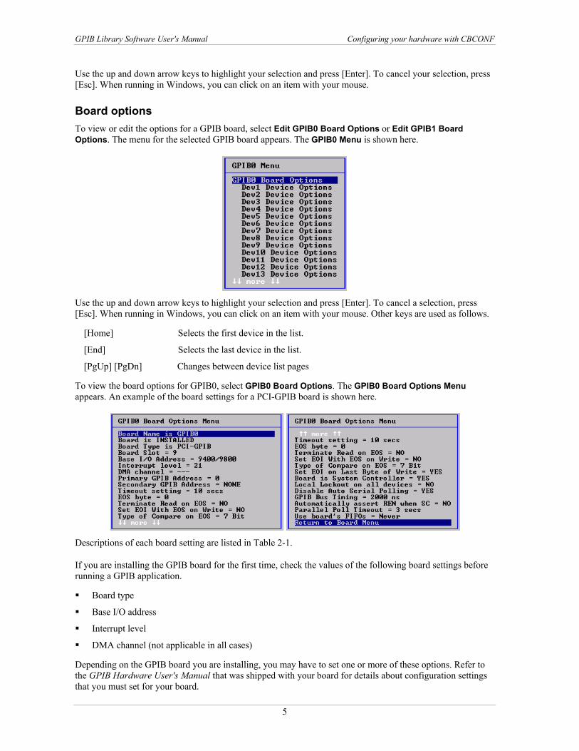
Board options To view or edit the options for a GPIB board, select Edit GPIB0 Board Options or Edit GPIB1 Board Options. The menu for the selected GPIB board appears. The GPIB0 Menu is shown here.
Use the up and down arrow keys to highlight your selection and press [Enter]. To cancel a selection, press [Esc]. When running in Windows, you can click on an item with your mouse. Other keys are used as follows.
[Home] Selects the first device in the list.
[End] Selects the last device in the list.
[PgUp] [PgDn] Changes between device list pages
To view the board options for GPIB0, select GPIB0 Board Options. The GPIB0 Board Options Menu appears. An example of the board settings for a PCI-GPIB board is shown here.
Descriptions of each board setting are listed in Ta . ble 2-1
If you are installing the GPIB board for the first time, check the values of the following board settings before running a GPIB application.
Board type
Base I/O address
Interrupt level
DMA channel (not applicable in all cases)
Depending on the GPIB board you are installing, you may have to set one or more of these options. Refer to the GPIB Hardware User's Manual that was shipped with your board for details about configuration settings that you must set for your board.
5

GPIB Library Software User's Manual Configuring your hardware with CBCONF
Table 2-1. CBCONF board options Board option Description Board Type The GPIB library supports a number of different types of GPIB boards. The choice selected
here must match the board that you have installed. If not, the library generates an ECFG error (error code = 252). Refer to the GPIB Hardware User's Manual that came with your board (or the board itself) to determine the board type. Install a PC2A board as either ISA-CIO-PC2A or ISA-GPIB-PC2A. If you have just
purchased the board, select ISA-GPIB-PC2A. If you are updating software for a CIO-PC2A board purchased before 1997, select ISA-CIO-PC2A.
Install a PCI-GPIB-300K or PCI-GPIB-1M board as PCI-GPIB. If you are not sure of your board type, select a board type from the menu. The CBTEST program will detect if it is not correct
Board Slot
Some GPIB boards (PCI-GPIB and PCM-GPIB) are configured based on the slot number that they are plugged into. For these boards, Board Slot is the slot number that the board is currently plugged into. This menu item is set automatically by the configuration program. If you install more than one board, the library uses the slot number to differentiate them.
Base Address
The base I/O address that the board is configured for. Set the board address so that it does not conflict with another board installed in the system. When more than one GPIB board is installed, set each to a different base address. On some boards (ISA-GPIB, ISA-GPIB/LC, PC2A) the base address is set with switches on the board. Refer to the board's GPIB Hardware User's Manual for details. When you change the address switches, you must also change this software configuration. The boards are factory set to the default base address. In typical installations, this default address can be used. You may have to change the address to prevent conflicts with other boards in your system. Important: For proper operation, the switch settings for base address on the board must match the base address setting in CBCONF.
Interrupt Level
The hardware interrupt (IRQ) line that the board is configured for. Configure the board's interrupt level so that it does not conflict with any other board that is installed in the system. If you have more than one GPIB board installed, set them to different interrupt levels. On some GPIB boards, the interrupt level is controlled entirely by this selection on CBCONF's Board Options menu. Important: Some boards (PC2A) have switches and jumpers on the boards that must be changed any time you change the Interrupt Level. Refer to your board's GPIB Hardware Manual for details about setting the Interrupt Level of your board.
DMA Channel
The DMA channel that the board is configured for. The board should be configured for a DMA channel that does not conflict with any other board that is installed in the system. If you have more than one GPIB board installed they must be set to different DMA channels. Some GPIB boards do not use DMA. When those board types are selected, the DMA Channel option is disabled. Other GPIB boards (PC2A and ISA-GPIB/LC) can use a DMA channel for high speed operation. The software comes from the factory set for DMA Channel 3. If you know that another board in your system already uses this DMA Channel then select a different channel or set the DMA Channel=NONE to disable DMA operation. Important: Some boards (PC2A) have jumpers on the boards that must also be changed, any time you change the DMA Channel. Refer to your board's GPIB Hardware User's Manual for details about setting the DMA Channel of your board.
Primary GPIB Address
Each GPIB device must have a unique bus address. This choice let's you set the board's address (0 through 30). Set the GPIB board to an address that does not conflict with any other device on the GPIB bus.
Secondary GPIB Address
GPIB devices can use extended addressing to increase the number of addresses that can be supported on a single bus. This choice let's you set the board's secondary address. The default setting is NONE, which disables extended addressing for the board.
6

GPIB Library Software User's Manual Configuring your hardware with CBCONF
Board option Description Timeout Setting
The amount of time that each I/O function waits for data before giving up and returning an EABO error. The default timeout is 10 seconds. For longer operations, for example when you transfer a very large mount of data, you may have to increase the Timeout Setting. Refer to Table 4-5 "Timeout codes" on page 77.
EOS Byte
There are two methods for devices to indicate the last byte in a transfer of multiple bytes. The most common method is for the sending device to assert the EOI line before sending
the last byte. This method is automatically supported by the GPIB library. The second method involves sending an extra End-Of-String (EOS) character to indicate
the end of data. A common EOS Byte is the linefeed character (decimal 10). In most cases, you do not have to set the EOS Byte since most devices rely on the EOI line instead. The default value for EOS Byte is 0.
Terminate Read On EOS
Some devices signal the last byte of a transfer by sending an EOS byte. When set to YES, all read operations automatically terminate whenever the EOS byte is received. If you set this option to YES, you must also set the EOS Byte (described above). The default value for this choice is NO. In most cases, it will never need to be set to YES.
Set EOI With EOS on Write
If you set this option to YES, all write operations automatically assert the EOI line whenever the EOS byte is transmitted. If you set this option to YES, be certain to also set EOS Byte (described above). The default value for this choice is NO. In most cases, it will never need to be set to YES.
Type of Compare on EOS
This option controls whether checks for the EOS byte use a 7 or 8 bit compare. This option has no affect unless Terminate Read On EOS or Set EOI With EOS on Write is set to YES.
Set EOI on Last Byte of Write
When set to YES, the library automatically asserts the EOI line before sending the last byte in a series of bytes. This is the most common method of signaling the end of a transfer. The default for this option is YES. Do not set to NO unless all devices that the board communicates with use an EOS byte instead.
Board is the system controller
There should always be one (and no more than one) system controller in a GPIB system. Ordinarily the board is the system controller, so the default value for this option is YES. If there are multiple boards or multiple computers attached to the GPIB system, configure one of them as system controller, and set the others to NO.
Local Lockout On All Devices
This option determines whether GPIB devices are automatically locked out of local operation whenever they're being programmed remotely by this board. The default setting is NO.
Disable Auto Serial Polling
This option enables/disables automatic serial polls whenever any device asserts the SRQ line. The default choice is YES, which disables the auto serial poll.
Bus Timing This option sets the T1 handshaking delay that the board uses to send data over the bus. This delay is part of the IEEE 488.2 specification. The default value is 500 ns. If the total length of all GPIB cables in your system is less than 15 meters, then the T1 delay can be set to 350 ns (except on PC2A boards).
Automatically Assert REN When SC
This option controls whether the Remote Enable (REN) line is asserted whenever the board is in use. The default choice is YES. If it is set to NO, the only time REN is asserted is when it is explicitly set with the ibsre or RemoteEnable routines.
Parallel Poll Timeout
This option controls how long the library waits when doing a parallel poll before reading the data from the bus. The default setting is 2 µsec. In some cases, if you are using a bus extender it may be necessary to increase the delay to 10 µsec.
Use Board’s FIFOs?
This option controls whether the library utilizes the FIFOs on those boards which have FIFO capability. The FIFOs can enhance performance on those applications which transfer large volumes of data. There are three options: NEVER, WHERE APPROPRIATE and ALWAYS. We recommend that you first get your application running without the FIFOs and then later enable them to see if there is any performance improvement.
7
GPIB Library Software User's Manual Configuring your hardware with CBCONF
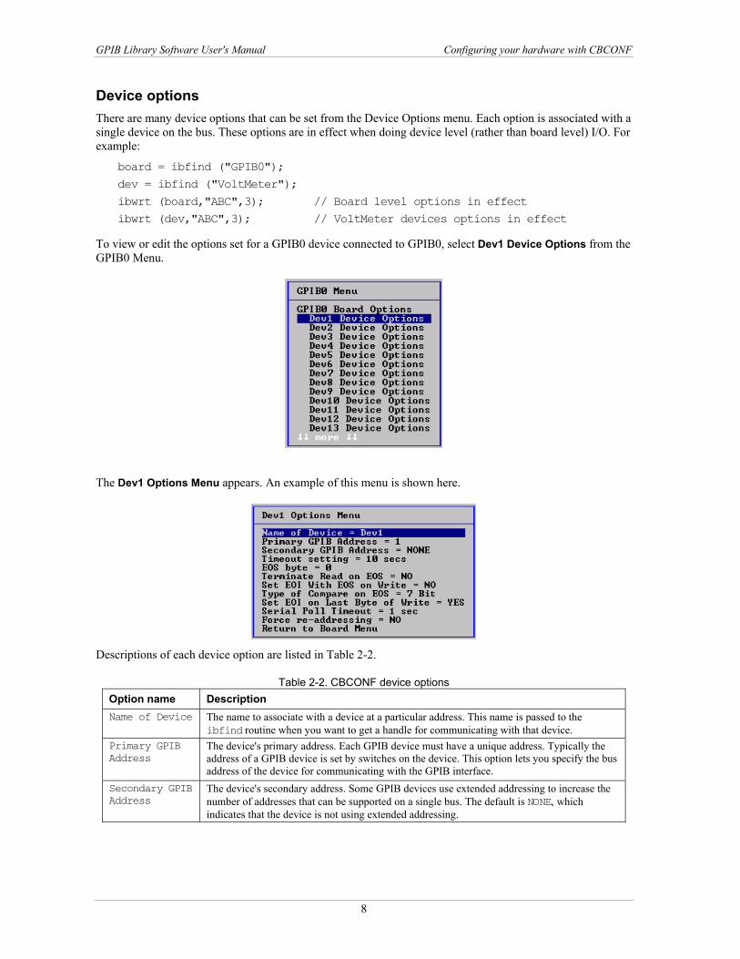
Device options There are many device options that can be set from the Device Options menu. Each option is associated with a single device on the bus. These options are in effect when doing device level (rather than board level) I/O. For example:
board = ibfind ("GPIB0"); dev = ibfind ("VoltMeter"); ibwrt (board,"ABC",3); // Board level options in effect ibwrt (dev,"ABC",3); // VoltMeter devices options in effect
To view or edit the options set for a GPIB0 device connected to GPIB0, select Dev1 Device Options from the GPIB0 Menu.
The Dev1 Options Menu appears. An example of this menu is shown here.
Descriptions of each device option are listed in Table 2-2.
Table 2-2. CBCONF device options Option name Description Name of Device The name to associate with a device at a particular address. This name is passed to the
ibfind routine when you want to get a handle for communicating with that device. Primary GPIB Address
The device's primary address. Each GPIB device must have a unique address. Typically the address of a GPIB device is set by switches on the device. This option lets you specify the bus address of the device for communicating with the GPIB interface.
Secondary GPIB Address
The device's secondary address. Some GPIB devices use extended addressing to increase the number of addresses that can be supported on a single bus. The default is NONE, which indicates that the device is not using extended addressing.
8

GPIB Library Software User's Manual Configuring your hardware with CBCONF
Option name Description Timeout Setting
Timeout Setting is the amount of time that each I/O function waits for data when communicating with this device. If the device does not respond within the specified period, it gives up and returns an EABO error. The default timeout is 10 seconds (10 secs). In cases where it is expected that an operation takes longer (transfer of a very large mount of data, for example) you may have to increase the Timeout Setting.
EOS Byte There are two methods for devices to indicate the last byte in a transfer of multiple bytes. The most common method is for the sending device to assert the EOI line before sending the last byte. This method is automatically supported by the GPIB library. The second method involves sending an extra End-Of-String (EOS) character to indicate the end of data. A common EOS Byte is the linefeed character (10). In most cases, you will not need to set the EOS Byte since most devices rely on the EOI line instead. The default value for the EOS Byte is 0. Note: You cannot use EOS with the FIFOs enabled.
Terminate Read On EOS
Some devices signal the last byte of a transfer by sending an EOS byte. If you set this option to YES, all read operations with this device automatically terminate whenever the EOS byte is received. If you set this option to YES, be certain to also set EOS Byte (described above). The default value for this choice is NO. In most cases, it will never need to be set to YES.
Set EOI With EOS on Write
If you set this option to YES, all write operations with this device automatically assert the EOI line whenever the EOS byte is transmitted. If you set this option to YES, be certain to also set the EOS Byte (described above). The default value for this choice is NO. In most cases, it will never need to be set to YES.
Type of Compare on EOS
Controls whether checks for the EOS byte use a 7 or 8-bit compare. Has no affect unless you set Terminate Read On EOS or Set EOI With EOS on Write to YES.
Set EOI on Last Byte of Write
When set to YES, the library asserts the EOI line before sending the last byte in a series of bytes. This is the most common method of signaling the end of a transfer. The default is YES. Do not set to NO unless the devices uses an EOS byte instead.
Serial Poll Timeout
This option controls how long the library waits when doing a serial poll before it gives up. The default setting is 1 sec. If the serial poll with this device returns an EABO error, try increasing this value.
Force re-addressing
Determines whether the device is specifically addressed on each access. When set to NO, once the device is addressed for either listen or talk, all subsequent access to the device is done without sending the addressing command if the access type matches the addressing. For example, if a particular device is read five times (with no intervening write), only the first read includes the "address to talk" command. When Force re-addressing is set to YES, every access to the device includes the appropriate addressing command. The default setting for this option is NO.
Setting board names, device names and addresses You can use CBCONF to assign a name to each device on your GPIB bus. The initial configuration lists 16 devices (Dev1 - Dev16) connected to each GPIB board. Each name is associated with a unique GPIB address. By default, "Dev1" is set for address 1, "Dev2" = address 2, etc. You can keep these default names and your programs can refer to "Dev1" or "Dev2". In that case, you are in effect still referring to the devices by addresses.
You can also enter a meaningful name for each device that is independent of its address. For example, if you have a voltmeter at address 4 and a signal generator at address 7 on your bus, edit the name and address of each device as follows.
1.
2.
3. 4.
From CBCONF's Main Menu, select "Edit GPIB0 Board Options".
Device names are listed at the bottom of the GPIB0 Menu as Dev1 - Dev16. Select "Dev1 Device Options".
The Dev1 Options Menu appears. Select "Name of Device" and press [Enter]. At the prompt, type in "VoltMeter" and press [Enter].
9

GPIB Library Software User's Manual Testing your GPIB hardware with CBTEST
The menu title changes to VoltMeter Options Menu. 5. 6.
Select "Primary GPIB Address" and press [Enter]. At the prompt, type in "4" and press [Enter].
Repeat this procedure to change the name of Dev2 to SigGen and the address to 7. After the system is configured with these names, you can write a program that communicates with devices called VoltMeter and SigGen. The program does not reference any GPIB addresses.
If you change the address of either device, you do not have to change the program. Rerun CBCONF and change the address that is associated with the device name.
After configuring the board, you should test the communication between your GPIB board and device(s). Refer to Testing your GPIB hardware with CBTEST below for instructions.
Testing your GPIB hardware with CBTEST
CBTEST is a quick-test program that verifies that the GPIB board is installed and configured correctly. CBTEST displays the current hardware configuration (board type, base address, interrupt level, DMA channel) that you selected with the CBCONF program. When installed with the 32-bit library, CBTEST is named CBTEST32.
CBTEST checks that the software and hardware configurations match, and that the hardware is working. If it reports any problems, verify that the switch and jumpers settings on the board, if any, are correct and that they match those shown in the CBCONF program.
Testing communication with GPIB devices with CBIC
CBIC is an interactive program that lets you type GPIB commands and execute them immediately rather than writing a program. Before you write your first GPIB program, practice with the CBIC program. CBIC lets you verify the device addressing, cabling, and proper commands for the instruments that you are using. When installed with the 32-bit library, CBIC is named CBIC32.
Find/Set Device Addresses — You should know the GPIB addresses that your GPIB devices are configured for. If not, refer to the device's User Manual for instructions on how to set the GPIB address. Set each instrument to a different address. The default address for the GPIB board is 0. Do not set any device to address 0 unless you have changed the board address.
Plug in GPIB cables — Connect the GPIB board to the device with a standard GPIB cable. Connect one end to your GPIB board, and the other end to the GPIB device. If you have more than one GPIB device, "daisy-chain" the cables between them.
Find List of Device's GPIB Commands — Each GPIB device understands its own set of commands. For example, on a Fluke 45 Voltmeter you would send the command "vac" to select the volts AC range. On a different voltmeter you may have to send a different command to perform the same function. Refer to the device's user manual for a list of the GPIB commands supported by the device.
When you run CBIC, the program displays a copyright message followed by a ":" prompt.
To execute GPIB library routines, type the routine at the prompt. Refer to Chapter 4 GPIB 488.1 Library Reference on page 29, and Chapter 5 GPIB-488.2 Library Reference on page 87 for details on each library routine. You should perform the following CBIC tests to get you started, and to show you how to use the GPIB library and CBIC program. The tests may also identify common installation/configuration problems.
10
GPIB Library Software User's Manual Testing communication with GPIB devices with CBIC
Testing with 488.2 commands At the ":" prompt, type the following command:
: ibfind gpib0
The prompt should change to "gpib0:"
Finding the listeners on the bus
If you are using an ISA CIO-PC2A board (or older 488.1 PC2A board), skip to Sending a Command below.
Enter the FindLstn command at the gpib0: prompt. This routine searches the GPIB bus for listeners that are specified by an address list. It should print a list containing the addresses of all devices within the address list that you have connected to the GPIB board.
GPIB0: FindLstn
the program responds with the following prompt. Type each address followed by [Enter]. Press [Enter] again at end of list
Enter address:
Enter each GPIB address where you expect to find a device. For example, if you have three instruments attached to the GPIB bus that you think are at addresses 3, 4, and 5, you would respond:
Enter address: 3 Enter address: 4 Enter address: 5 Enter address:
The FindLstn function then checks the bus to see if any instruments respond at the specified addresses.
Responding Devices:
Device at address = 3 Device at address = 5
In this example, two devices were found - one at GPIB address 3 and one at address 5.
When you type FindLstn, check the addresses that are returned and make sure that they match the addresses that you believe your devices are set for. If not, check the address settings on those devices. If FindLstn returns an ECAP error, you are using a GPIB board which does not support the FindLstn routine, such as the ISA CIO-PC2A. Proceed to Testing with 488.1 commands on page 13.
Sending a command
Refer to the list of GPIB commands that your device understands. Choose a command that should cause some visible response on the front panel of the device. That will vary depending on the instrument. Often, a command that selects a range has a visible indicator.
Use the GPIB library Send routine to send the command to the device. The Send routine in the GPIB library has four arguments. When calling any of the library routines from within CBIC, the program always sends the first argument (board or dev) automatically. The three other arguments for Send are address, data, and eotmode.
Set address to the device's GPIB address.
Data is the command string you wish to send. Set eotmode to DABend
11

GPIB Library Software User's Manual Testing communication with GPIB devices with CBIC
There are two ways to execute a GPIB library routine within CBIC: You can type in the name of the routine and CBIC prompts you for each of the arguments. You can also type them in all on one line, separated by spaces. Here's an example of each method:
GPIB0: Send Enter address of device : 5 Enter string to be written : vac Enter EOTMode (DABend, NULLend, or NLend) : DABend GPIB0: Send 5 vac DABend
Using either method, the command "vac" is sent to the device. On a Fluke45 voltmeter, the "vac" command selects the Volts AC range. The front panel indicator switches to "VAC".
On-line help
If you forget the arguments for a command, use CBIC's help function. Type help and the name of the GPIB library routine. For example: GPIB0: help send For more general help, enter the word "help" by itself. You can then choose from a variety of topics.
Receiving data from the device Refer to the list of GPIB commands that your device understands. Find a command that returns data. It will vary depending on the instrument. On many instruments, you send a command to the instrument (with the Send routine) and it will send back a response which you can read with the GPIB library's Receive routine.
For example, if you send the Fluke 45 Voltmeter the command "VAL?", it will take a measurement and then send the result back over the GPIB bus. This sequence is executed with CBIC as follows:
GPIB0: Send 5 val? DABend GPIB0: Receive 5 100 STOPend Data: -1.345e1
The arguments for the Receive routine are:
5 Address of the meter
100 Maximum number of characters to read
STOPend Causes Receive to stop reading when it receives the End (EOI) signal
-1.345e1 The reading returned by the meter.
Some GPIB instruments work a bit differently. For example, the Fluke 8840 DMM always returns the most recent measurement whenever you call the Receive routine. This meter doesn't require that you ask for each measurement by Send'ing a command.
The Fluke 8840 meter works this way:
GPIB0: Receive 5 100 STOPend Data: -1.345e1
To read it again, you could type the same Receive command. You can also use the CBIC "!" command. The "!" command executes the most recent command again.
GPIB0: ! Data: -1.347e1 GPIB0: ! Data: -1.422e1
12

GPIB Library Software User's Manual Testing communication with GPIB devices with CBIC
Testing with 488.1 commands In the examples above you were using the 488.2 GPIB library routines. The 488.2 Library always passes a GPIB address or a list of addresses as an argument to the routines.
The 488.1 routines are simpler to use because they use the device information that was configured with the CBCONF program. For example, if you configured a device named voltmeter with the CBCONF program, you communicate with the device as follows:
: ibfind voltmeter voltmeter:
The prompt changes to "voltmeter:" to indicate that it is now the current device.
The most common error that can occur at this point is that the device could not be found. The following message appears on the screen:
Cannot find a configured device named voltmeter.
There are two possible reasons for this — you either typed the name incorrectly, or you have not configured a device named "voltmeter" with the CBCONF program. Run CBCONF and check the name that you gave the device. Refer to Device Options on on page 8.
Sending a command with ibwrt
The ibwrt routine in the 488.1 library performs the same function as the Send routine in the 488.2 library. They both send a command to a GPIB device.
ibwrt is simpler to use because it has fewer arguments. The Send arguments address (the device's GPIB address) and EOTmode (the termination method) are not required when calling ibwrt. These arguments are automatically read from "voltmeter" configuration information that was set in the CBCONF program.
To send the command "vac" to the device called "voltmeter", do the following:
voltmeter: ibwrt vac
Receiving data from the device
Receiving data with the ibrd routine is also a bit simpler than with the 488.2 library's Receive routine. Once again, fewer arguments need to be passed because it uses the configuration information in the GPIB.CFG file that is created by the CBCONF program.
This example shows you how to read a measurement from a Fluke 45 meter:
voltmeter: ibwrt val? voltmeter: ibrd 100 (100 is maximum characters to receive) Data: -1.345e1
At this point, you can begin exploring the operation of your GPIB devices. You can use the CBIC program to quickly experiment with your devices using ibrd and ibwrt (or Send and Receive) and get a good idea of what they do. You can also explore all of the other routines in both the 488.1 and the 488.2 Library by typing them in at the CBIC prompt.
Refer to Chapter 4 GPIB 488.1 Library Reference on page 29, and Chapter 5 GPIB-488.2 Library Reference on page 87 for details on each library routine. You can also enter "help" at the CBIC prompt to display information about each command.
13

3Programming with the GPIB Library The GPIB library contains two different and complete GPIB libraries. Each library is modeled on a corresponding National Instruments library.
Original 488.1 library — the 488.1 library (also referred to as the original library), consists of all of the functions and subroutines that begin with the letters "ib" (or "il"). This library uses a concept of device names and handles rather than GPIB addresses when referring to GPIB devices. There are two advantages to this approach:
The GPIB addresses of each device are not stored in the program, so the same program can run on different buses where the addresses of each device are different.
The program can refer to each device with an intelligible name rather than a number (the GPIB address).
488.2 library — this library consists of all the routines that do not begin with the letters "ib", or "il" for Basic. These routines refer to all devices on the bus by their GPIB addresses rather than by names. The Device IO section on page 15 does not apply to the 488.2 library.
The GPIB library includes different routines that allow you to control the operations of the GPIB bus in a very specific manner. You may find the number of routines included in the GPIB library intimidating, however, in most applications you need to use only a small subset of these routines.
The routines are divided into two distinct libraries. All routines which begin with "ib" (or "il") are part of the "488.1" or "Original GPIB library." All other routines are part of the "488.2 library." You only need to use one or the other library. Each library provides a different method of performing the same tasks. The choice of which library to use is a matter of personal preference. Refer to Testing with 488.2 commands on page 11, and Testing with 488.1 commands on page 13 for information about choosing which library to use. If you use the original GPIB library, you can perform either Board Level or Device Level operations.
General concepts This section explains the difference between routines which use Device I/O and those which use Board I/O, the use of device handles, and the global variables used by the library routines.
Device vs. Board I/O The most typical GPIB operations are sending commands to a device attached to the bus and reading back responses. To do this, program the GPIB board to execute these steps:
1. 2. 3. 4. 5. 6. 7.
Address the selected device as a Listener. Send the secondary address if used. Address the board itself as the GPIB Talker. Send the command bytes to the device. Read the response from the device. Send the GPIB Unlisten (UNL) message. Send the GPIB Untalk (UNT) message.
The original GPIB library interface is comprised of two different types of routines: Board I/O and Device I/O. These routines are described in Chapter 4 GPIB 488.1 Library Reference. You can program the board using either Board I/O routines or Device I/O routines to perform the sequence of operations outlined above.
14
GPIB Library Software User's Manual Device I/O
The 488.2 library is all "Board I/O" in that you always supply the board ID and the device address. Refer to Chapter 5 GPIB 488.2 Library Reference on page 87.
Device I/O
It is usually easier to use the Device I/O routines. Device I/O is very simple to use and understand. Device I/O routines are higher-level routines which conceal most of the underlying complexity of GPIB operations. These commands use the device names you assigned with CBCONF. The Device I/O routines automatically take care of all of the low-level details involving GPIB messages and addressing. For example, to accomplish the seven steps listed above, you use only three routines:
ibfind — to open the device
ibwrt — to send the instrument command
ibrd — to read the data back from the device
Board l/O In comparison, the Board I/O routines are low-level routines. If you use them, you must understand how the GPIB operates in detail. Generally, the only time you need to use Board I/O is if it is impossible to perform the same operation using device I/O, such as passing control from one controller to another.
To perform the same task as the seven steps outlined in Device I/O vs Board I/O on page 14 (send a command to a device), you need to know the codes for the various forms of addressing and the codes for the GPIB Unlisten and Untalk commands.
Use the routines in this sequence:
1. 2. 3. 4. 5.
ibfind — to open the board ibcmd — to send the address of the talker and listener ibwrt — to send the command to the device ibrd — to read the data back from the device icbmd — to send the Unlisten (UNL) and Untalk (UNT) commands
Device handles
Most of the routines in the 488.1 library have a device handle as the first argument. The first GPIB call in your program is usually ibfind. This routine "opens" a board or device and returns a GPIB board or device handle. If you pass the name of a board (as assigned by CBCONF), it returns a board handle. Likewise, if a device name is passed, a device handle is returned. Some library routines only work with device handles, some only with board handles, and some with both.
Configure the board and device names before writing a program You assign board/device names with the CBCONF configuration program. It is important that you run your configuration program and make any necessary changes before you write your application program.
Global variables The following global variables are used in all programming languages:
ibsta Status Word
iberr Error Codes
ibcnt,ibcntl Count Variables (short/long)
15

GPIB Library Software User's Manual Example programs
The ibsta and iberr variables are briefly explained here. For additional information about ibsta, refer to Appendix B - IBSTA on page 119. For additional information about iberr, refer to Appendix C – IBERR on page 121.
For additional information about ibcnt and ibcntl, refer to the routines which return them.
ibsta — the status word
Every library routine updates a status word (ibsta) which indicates the results of the last operation. Your application program can test each bit of this word and then take appropriate action. The ibsta variable is discussed further in Appendix B - IBSTA.
iberr — the error variable
If a GPIB error occurs during a routine, its corresponding error code is returned into the variable iberr. Possible error codes and their meanings are listed in Appendix C – IBERR.
ibcnt and ibcntl — count variables
These variables contain an integer which describes how many bytes were actually transferred during a read or write operation. ibcnt is an integer value (16-bits wide) and ibcntl is a long integer value (32-bits wide).
Example programs This section provides three example programs:
The first program illustrates a GPIB application using the 488.2 library.
The second program illustrates Device Level I/O with the 488.1 library.
The third program illustrates and Board Level I/O with the 488.1 library.
When you install the software, example programs for C, Delphi, and Visual Basic are also installed into sub folders named c, delphi and vb.
You should run the CBIC program to execute specific library routines using your system configuration. This will help you understand what types of responses you will obtain.
Example program 1: simple I/O with the 488.2 Library This example illustrates a simple GPIB application. It sends command strings to a Fluke45 Multimeter to initialize it, select a measurement range and make a measurement. It reads the measurement back from the meter and prints it on the screen. It uses the following commands which are specific to the Fluke 45:
*RST ‘Reset the meter VDC ‘Select Volts DC Range VAL? ‘Take a measurement and send it over the GPIB bus
The program assumes that the Fluke45 is set for GPIB address 3.
BASIC programming language const METER_ADR = 3 const BOARD_NUM = 0 buffer$ = space$(100) DevClear (BOARD_NUM, METER_ADR) Send (BOARD_NUM, METER_ADR, "*RST", DABend) Send (BOARD_NUM, METER_ADR, "VDC",DABend)
16
GPIB Library Software User's Manual Example programs
Send (BOARD_NUM, METER_ADR, "VAL?", DABend) Receive (BOARD_NUM, METER_ADR, buffer$, 100, STOPend) PRINT "Voltage = ";buffer$
C programming language #define METER_ADR 3 #define BOARD_NUM 0
int Board; char buffer[100]; DevClear (BOARD_NUM, METER_ADR); // Clear the meter Send (BOARD_NUM, METER_ADR, "*RST", DABend); Send (BOARD_NUM, METER_ADR, "VDC", DABend); Send (BOARD_NUM, METER_ADR, "VAL?", DABend); Receive (BOARD_NUM, METER_ADR, buffer, STOPend); printf ("Voltage = %s\n", buffer);
Example program 2: device I/O with the 488.1 library This example performs the same operations as the example above. Instead of using the 488.2 Library it uses the original 488.1 GPIB library.
The following examples show a simplified program (no error checking) for reading a DC voltage measurement from the volt meter. The program assumes that the name "VoltMeter" has been assigned to the Fluke 45 (via the CBCONF program).
BASIC programming language buffer$ = space$(100) CALL ibfind ("VoltMeter", device%) ' Open device CALL ibclr (device%) ' Clear the device CALL ibwrt (device%, "*RST") ' Reset meter CALL ibwrt (device%, "VDC") ' Select volts DC range CALL ibwrt (device%, "VAL?") ' Ask for current value CALL ibrd (device%, buffer$) ' Read current value PRINT "Voltage = "; buffer$;
C programming language int device; char buffer[100]; device = ibfind ("Volt Meter"); /* Open device */ ibclr (device); /* Clear the device ibwrt (device, "*RST"); /* Reset meter */ ibwrt (device, "VDC"); /* Select volts DC range */ ibwrt (device, "VAL?"); /* Ask for current value */ ibrd (device, buffer,100); /* Read current value */ printf ("Voltage = %s\n" buffer);
17

GPIB Library Software User's Manual Example programs
Example program 3: board I/O with the 488.1 library Board I/O requires a more detailed understanding of the GPIB bus and commands. Your program must explicitly send all of the GPIB command codes to set up each GPIB operation. For example, you must set up the addressing for talker and listener, etc.
The following example performs the same operations as the Device I/O example while using Board I/O routines. You need to be familiar with both the device-specific commands and also the GPIB Multiline Interface Messages (for example MLA, MTA, etc.). The program assumes that the Fluke 45 meter is at GPIB address 13.
BASIC programming language CALL ibfind ("GPIB0", board%) ' Open board CALL ibsic (board%) ' Send IFC message CALL ibsre (board%, 1) ' Turn on REN command$ = chr$(&H11) + "-" + chr$(&H14) +"@" CALL ibcmd (board%, command$) ' LL0, MLA13, DCL, MTA0 CALL ibwrt (board%, "*RST") ' Reset meter CALL ibwrt (board%, "VDC") ' Select volts DC range CALL ibwrt CALL ibwrt (board%, "VAL?") ' Ask for current value command$ = "?" + "_" + "M" + " " CALL ibcmd (board%, command$) ' UNL, UNT, MTA13, MLA0 buffer$ = space$(100) CALL ibrd (board%, buffer$) ' Read current value PRINT "Voltage = "; buffer$;
C programming language int board; char buffer[100], *command; board = ibfind ("GPIB0"); /* Open board */ ibsic (board%); /* Send IFC message */ ibsre (board%,1); /* Turn on REN */ command = "\0x11\0x2d\0x14\0x40"; ibcmd (board%, command, 4); /* LL0, MLA13, DCL, MTA0 */ ibwrt (board%, "*RST", 4); /* Reset meter */ ibwrt (board%, "VDC", 3); /* Select volts DC range */ ibwrt (board%, "VAL?",4); /* Ask for current value */ command = "\0x3f\0x5f\0x4d\0x20"; ibcmd (board%, command, 4); /* UNL, UNT, MTA13, MLA0 */ ibrd (board%, buffer); /* Read current value */ printf ("Voltage = %s\n" buffer);
Error checking The above example programs do not include any error checking. In a real program, you should always check for errors after each call to the library. The easiest way to do this is to write one error checking/handling routine and call it after every call to the library.
The error reporting mechanism involves three global variables - ibsta, iberr and ibcnt. If an error occurred during a call to the library then the EERR bit in ibsta is set (to 1) and iberr will contain an error code. If the error code indicates that a DOS error occurred, then ibcnt contains the DOS error code.
18

GPIB Library Software User's Manual Example programs
The following examples show how to use error handling routines using BASIC and C languages.
BASIC programming language
CALL ibwrt (device%, "*RST") ' After each call to GPIB Call CheckGPIBError ' check for errors SUB CheckGPIBError () IF (ibsta% AND EERR) <> 0 THEN PRINT "*** ERROR -" SELECT CASE iberr% CASE EDVR PRINT "EDVR=DOS Error" CASE ECIC PRINT "ECIC=Board is not Controller In Charge" CASE ENOL PRINT "ENOL=No listener" CASE EADR PRINT "EADR=Address Error" CASE EARG PRINT "EARG=Invalid argument passed to library" CASE ESAC PRINT "ESAC=Board is not system controller" CASE EABO PRINT "EABO=I/O Operation terminated" CASE ENEB PRINT "ENEB=No GPIB board installed" CASE EOIP PRINT "EOIP=Background I/O already in progress" CASE ECAP PRINT "ECAP=Board missing required capability" CASE EFSO PRINT "EFSO=File system error" CASE EBUS PRINT "EBUS=Command error" CASE ESTB PRINT "ESTB=Status byte lost" CASE ESRQ PRINT "ESRQ=SRQ line is stuck on" CASE ETAB PRINT "ETAB=Table overflow" END SELECT IF iberr% = EDVR THEN PRINT "DOS Error Code=";ibcnt% IF ibsta% AND TIMO THEN PRINT "GPIB device timed out" END IF END SUB
19

GPIB Library Software User's Manual Example programs
C programming language ibwrt (device, "*RST", 4); /* After each call to GPIB */ CheckGPIBError(); /* check for errors */ void CheckGPIBError (void) { if (ibsta & EERR) { printf ("*** ERROR -"); switch (iberr) { case EDVR printf ("EDVR=DOS Error\n"); case ECIC printf ("ECIC=Board is not Controller In Charge\n"); case ENOL printf ("ENOL=No listener\n"); case EADR printf ("EADR=Address Error\n"); case EARG printf ("EARG=Invalid argument passed to library\n"); case ESAC printf ("ESAC=Board is not system controller\n"); case EABO printf ("EABO=I/O Operation terminated\n"); case ENEB printf ("ENEB=No GPIB board installed\n"); case EOIP printf ("EOIP=Background I/O already in progress\n"); case ECAP printf ("ECAP=Board missing required capability\n"); case EFSO printf ("EFSO=File system error\n"); case EBUS printf ("EBUS=Command error\n"); case ESTB printf ("ESTB=Status byte lost\n"); case ESRQ printf ("ESRQ=SRQ line is stuck on\n"); case ETAB printf ("ETAB=Table overflow\n");); } if (iberr == EDVR) printf ("DOS Error Code=%d\n", ibcnt);
20

GPIB Library Software User's Manual Programming language-specific information
if (ibsta% & TIMO) printf ("GPIB device timed out\n"); } return; }
Programming language-specific information The GPIB library is nearly identical in each of the supported languages. Each function is explained in Chapter 4 GPIB 488.1 Library Reference on page 29. The descriptions apply to all supported programming languages.
Developing Programs for Visual Basic for Windows The Visual BASIC interface combines support for both the 16-bit and 32-bit versions of Visual BASIC. If you are running Windows 3.x then you are using the 16-bit VB. If you are running Windows 95/98 then you may be running either the 16- or 32-bit version. Use VB's "Help","About Microsft Visual BASIC" menu choice to find out which it is.
The files that make up the Visual BASIC for Windows interface are listed here.
GPIB Library Component Used with 16-bit? Used with 32-bit? GPIB.DLL — the GPIB library Yes No GPIB-32.DLL — 32-bit "thunk" layer DLL No See note GPIB-16.DLL — 16-bit "thunk" layer DLL No See note GPIB-32.DLL — 32-bit GPIB library No See note GPIB-16.BAS — Visual BASIC (16-bit version) header file Yes No GPIB-32.BAS — Visual BASIC (32-bit version) header file No Yes GPIBVXD.386 — Device driver, loaded by \windows\system.ini file
Yes Yes
NTGPIBDD.SYS — Device driver for Windows NT/2000/XP No Yes Note: If you are using the 32-bit GPIB library, then the only DLL is GPIB-32.DLL. If you are using the 16-bit library with a 32-bit VB program, then you can employ the 16-bit GPIB library together with the "thunk" layer DLLs [GPIB-16.DLL and GPIB-32.DLL.]
Sample Programs The example programs are installed by default in the C:\GPIB_32\vb directory (C:\CBI_GPIB\vb directory for the 16-bit library).
vb16demo.mak - for the 16-bit version of VB
vb32demo.mak - for the 32-bit version of VB
Versions Supported Visual BASIC 3.0 and higher
Header File All VB programs that use the GPIB library must also include GPIB-16.BAS, GPIB-32.BAS or GPIB-32M.BAS file in the project.
To add the file to a project, select "File" and then "Add File" from the VB menu. You could also select "Project" > "Add Module". Select the appropriate header file depending on which version of VB you're using, and which version of the National Instruments GPIB library that you wish to be compatible with. Refer to the list above. National Instruments has two different versions of their GPIB library (NI 488.2 and NI-488.2M) that have slight incompatibilities between them. We have included two different header files (GPIB-32.BAS and GPIB-32M.BAS) that are compatible with each version of the National Instruments Library.
21
GPIB Library Software User's Manual Programming language-specific information
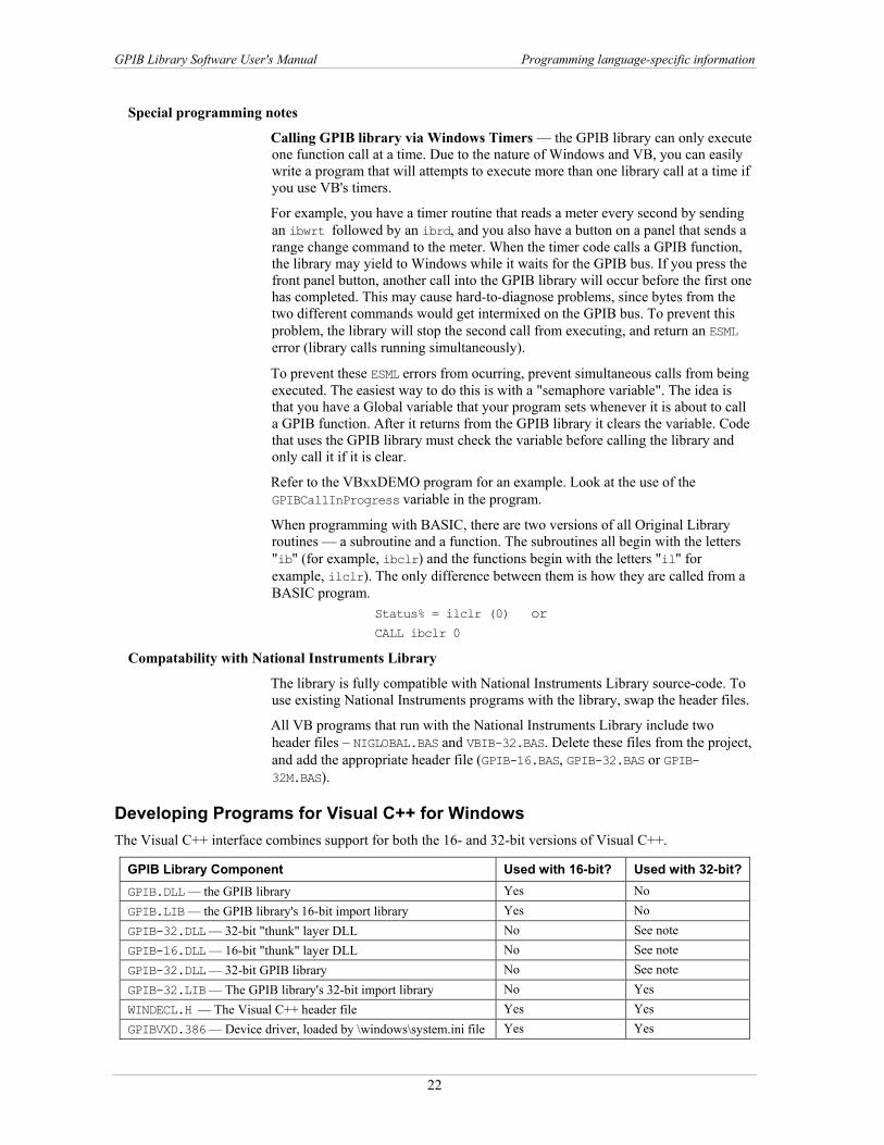
Special programming notes
Calling GPIB library via Windows Timers — the GPIB library can only execute one function call at a time. Due to the nature of Windows and VB, you can easily write a program that will attempts to execute more than one library call at a time if you use VB's timers.
For example, you have a timer routine that reads a meter every second by sending an ibwrt followed by an ibrd, and you also have a button on a panel that sends a range change command to the meter. When the timer code calls a GPIB function, the library may yield to Windows while it waits for the GPIB bus. If you press the front panel button, another call into the GPIB library will occur before the first one has completed. This may cause hard-to-diagnose problems, since bytes from the two different commands would get intermixed on the GPIB bus. To prevent this problem, the library will stop the second call from executing, and return an ESML error (library calls running simultaneously).
To prevent these ESML errors from ocurring, prevent simultaneous calls from being executed. The easiest way to do this is with a "semaphore variable". The idea is that you have a Global variable that your program sets whenever it is about to call a GPIB function. After it returns from the GPIB library it clears the variable. Code that uses the GPIB library must check the variable before calling the library and only call it if it is clear.
Refer to the VBxxDEMO program for an example. Look at the use of the GPIBCallInProgress variable in the program.
When programming with BASIC, there are two versions of all Original Library routines — a subroutine and a function. The subroutines all begin with the letters "ib" (for example, ibclr) and the functions begin with the letters "il" for example, ilclr). The only difference between them is how they are called from a BASIC program.
Status% = ilclr (0) or CALL ibclr 0
Compatability with National Instruments Library
The library is fully compatible with National Instruments Library source-code. To use existing National Instruments programs with the library, swap the header files.
All VB programs that run with the National Instruments Library include two header files – NIGLOBAL.BAS and VBIB-32.BAS. Delete these files from the project, and add the appropriate header file (GPIB-16.BAS, GPIB-32.BAS or GPIB-32M.BAS).
Developing Programs for Visual C++ for Windows The Visual C++ interface combines support for both the 16- and 32-bit versions of Visual C++.
GPIB Library Component Used with 16-bit? Used with 32-bit? GPIB.DLL — the GPIB library Yes No GPIB.LIB — the GPIB library's 16-bit import library Yes No GPIB-32.DLL — 32-bit "thunk" layer DLL No See note GPIB-16.DLL — 16-bit "thunk" layer DLL No See note GPIB-32.DLL — 32-bit GPIB library No See note GPIB-32.LIB — The GPIB library's 32-bit import library No Yes WINDECL.H — The Visual C++ header file Yes Yes GPIBVXD.386 — Device driver, loaded by \windows\system.ini file Yes Yes
22

GPIB Library Software User's Manual Programming language-specific information
GPIB Library Component Used with 16-bit? Used with 32-bit? NTGPIBDD.SYS — Device driver for Windows NT/2000/XP No Yes Note: If you are using the 32-bit GPIB library, the only DLL is GPIB-32.DLL. If you are using the 16-bit library with a 32-bit VC++ program, you can employ the 16-bit GPIB library together with the "thunk" layer DLLs GPIB-16.DLL and GPIB-32.DLL
Sample Programs The example program is installed by default in the C:\GPIB_32\C\ (32-bit) and C:\CBI_GPIB (16-bit) directories. Refer to the example program in the approriate directory.
Versions Supported Visual C++ for Windows — all versions
Header File All C or C++ programs that use the GPIB library must include the WINDECL.H file. Add the following line to the start of your program.
#include "windecl.h"
Adding the library to your project
Each program that uses the GPIB library must be linked to the appropriate Import Library file. There are two import libraries provided:
GPIB.LIB for the 16-bit Visual C++ GPIB-32.LIB for the 32-bit Visual C++
The details are not the same for different versions of Visual C++. It is beyond the scope of this document to try and cover all the different versions.
Note for Borland: To use the GPIB library with Borland C++, use the Borland IMPLIB tool to create a Borland-compatible import library. Also, depending on the particular Borland package (and version), you may need to make some small adjustments to the WINDECL.H include file.
Compatibility with National Instruments Library
The library is fully compatible with the National Instruments Library source code. To use existing National Instruments programs with the library, swap the header files and libraries.
All VC++ programs that run with the National Instruments Library include a header file - DECL-16.H or DECL-32.H. The "#include DECL-xx.H" in the C source code should be replaced with an include of the header file as described above.
All VC++ programs that run with the National Instruments NI-488.2M Library also include an OBJ file (GPIB-32.OBJ) in their project. Follow the instructions above for adding the library but before adding it, delete the National Instruments OBJ file from the project.
Developing Programs in QuickBASIC/BASIC (DOS) These files form the QuickBASIC/BASIC Interface:
GPIBQB.QLB A library of GPIB routines to be used with QuickBASIC
GPIBQB.LIB A library file linked to compiled programs to create stand-alone executable files.
DECL.BAS BASIC header file
Versions Supported QuickBASIC 4.0 and Higher
23

GPIB Library Software User's Manual Programming language-specific information
Preparing the Environment
Before you begin to write your programs, copy the following files from the GPIB install directory to your working directory.
GPIBQB.QLB
GPIBQB.LIB
GPIB.CFG
DECL.BAS
Header File Be sure to include the following line within your program: ‘$INCLUDE: ‘decl.bas’
Including this file allows QuickBASIC/BASIC to check that the correct number and type of parameters are specified for each routine called.
Using the GPIB library from within QuickBASIC
To Load the GPIB library, be sure that the file GPIBQB.QLB is located where QuickBASIC can find it. Then, invoke QuickBASIC by typing:
qb /Lgpibqb yourprog
where:
yourprog is the name of your program.
After you have entered the QuickBASIC environment, compile the program as you normally would.
Compiling with the Command Line Compiler
This process compiles the BASIC source code and links it to the BASIC and GPIB library files. Compile the code by typing:
bc /o /d yourprog.bas link yourprog,,,bcom45+gpibqb; where: yourprog is the name of your program.
bcom45 is the QuickBASIC Runtime library name.
gpbiqb is the linkable BASIC library file.
Also refer to the MAKEQB.BAT file in the \DOS_BAS subdirectory of your install directory.
Special Programming Notes
Parameters can be passed as either variables or constants. For example: DevName$ = "VoltMeter"
CALL ibfind (DevName$, Dev%)
is the same as: CALL ibfind ("VoltMeter", Dev%)
When programming with Quick BASIC, there are two versions of all Original Library routines - A subroutine and a function. The subroutines all begin with the letters "ib" (for example, ibclr) and the functions begin with the letters "il" (for example, ilclr). The only difference between them is how they are called from a BASIC program.
24
GPIB Library Software User's Manual Programming language-specific information
Status% = ilclr (0)
or CALL ibclr 0
SAMPLE.BAS illustrates the use of several of the GPIB library routines.
Developing GPIB Programs with HP VEE HP VEE is a graphic programming environment from Hewlett Packard that works with the GPIB library. HP Vee comes with hundreds of Instrument drivers that simplify the programming of most common GPIB instruments.
Enabling GPIB Support Within HP VEE
HP VEE automatically recognizes that the GPIB library has been installed on your system. However, if you also have a National Instruments GPIB library on your system, HP VEE may recognize the wrong library. In that case, you should rename or remove the following National Instruments files from your system.
\windows\system\gpib.dll
\windows\system\gpib-16.dll
\windows\system\gpib-32.dll
Earlier than HP Ver 4.0
If you are using a HP VEE version less than 4.0, GPIB support is automatically enabled. The GPIB board is installed as GPIB interface 14. All GPIB devices within HP VEE have a 4 digit address property - 14xx, where xx is the GPIB address of the device. For example if you have a signal generator set to GPIB address 7, then the address field for this device is set to 1407. This address (1407) should be used throughout VEE whenever you want to access that device.
Ver 4.00 If you are using version 4.0 (or greater) of HP VEE, first copy the GPIB DLL files from the C\gpib_32 directory into the \windows\system directory.
Run HP Vee. Select I/O from VEE's main menu bar, then select Instrument Manager to display the Instrument Manager dialog box. Press the refresh button on the right. The panel on the left updates with a new driver called HP-IB0. This is the GPIB library.
Select HP-IB0 on the left panel, then press the Edit.. button. A small Interface Configuration dialog box appears. Change the address field to 14, then select OK to close the dialog.
The HP-IB0 in the left pane has changed to HP-IB14. Select HP-IB14 and press the refresh button again. All devices that connected to the GPIB boards appear beneath the HP-IB14 icon in the left pane. Each device icon has a "?" superimposed on it to indicate that the system does not yet know what type of device it is.
Select one of the unknown devices and press "refresh" again. A small dialog box appears that says "OK to Send '*IDN?' to NewDevice. If you select OK, the system sends this command to the instrument. "*IDN?" is a standard (SCPI) command which instructs the device to send back an identification string. Many GPIB instruments respond to this command, and the system automatically recognizes which type of device it is.
25

GPIB Library Software User's Manual Programming language-specific information
Select one of the devices and press the Edit button. The address field should be set to a 4 digit number - 14xx, where xx is the GPIB address of the device. For example if you have a signal generator set to GPIB address 7, then the address field for this device is set to 1407. This address (1407) should be used throughout VEE to access that device.
Developing Programs in Professional Basic (DOS) These files form the Professional BASIC Interface:
GPIBPB.QLB A library GPIB routine to use within a Professional BASIC development environment.
GPIBPB.LIB A library file which is linked to compiled programs to create stand-alone executable files.
DECL.BAS BASIC header file Versions Supported Professional BASIC 4.0 and higher Preparing the Environment Before you begin to write your programs, copy the following files from the GPIB
install directory to your working directory: GPIBQB.QLB
GPIBQB.LIB
GPIB.CFG
DECL.BAS
Header File Be sure to include the following line within your program: '$INCLUDE:'decl.bas'
Including this file allows Professional BASIC to check that the correct number and type of parameters are specified for each routine called.
Compliling Your Program This process compiles the BASIC source code and links it to the BASIC and GPIB
library files. Compile the code by typing: bc /Fs yourprog.bas
link yourprog,,,gpibpb;
where:
yourprog is the name of your program.
gpbiqb is the linkable BASIC library file.
Refer also to the MAKEQB.BAT file in the \DOS_BAS subdirectory of your install directory.
Special Programming Notes Parameters can be passed as either variables or constants. For example: DevName$ = "VoltMeter"
CALL IBFIND (DevName$, Dev%)
is the same as: CALL IBFIND ("VoltMeter", Dev%)
26

GPIB Library Software User's Manual Programming language-specific information
When programming with BASIC, there are two versions of all Original Library routines - A subroutine and a function. The subroutines all begin with the letters "ib" (for example, ibclr) and the functions begin with the letters "il" (for example, ilclr). The only difference between them is how they are called from a BASIC program.
Status% = ilclr (0) or CALL ibclr 0
Sample Program SAMPLE.BAS illustrates the use of several of the GPIB library routines.
Developing Programs in Microsoft C/Turbo C/ Borland C/C++ (DOS)
There are several files which comprise this interface:
GPIBCL.LIB Library File for Microsoft C Large Model.
GPIBCM.LIB Library File for Microsoft C Medium Model.
GPIBCS.LIB Library File for Microsoft C Small Model.
DECL.H C Header file.
Versions Supported Microsoft C version 3.0 and later
Preparing the Environment Before you begin to write your programs, copy the following files to your working
directory:
GPIBCS.LIB (depending on memory model) GPIBCM.LIB
GPIBCL.LIB
DECL.H
GPIB.CFG
Header File When you write your program, make sure to include the line: #include <decl.h>
The DECL.H file is a header file which defines the GPIB library routines. In particular, it defines the type and number of parameters associated with each routine.
Compiling Your Program When the source code is compiled, it is linked to the appropriate GPIB.LIB file.
This process forms a stand-alone executable (.exe) file.
Compile your program in the normal manner and link it with the correct library.
For example, at the DOS prompt, you might type either: cl yourprog.c /link gpibcs.lib
or cl /c yourprog.c;
link yourprog,,,gpibcs/lib;
This assumes you are using the small memory model. Also refer to the MAKEMC.BAT (Microsoft C) and MAKETC.BAT (Turbo C) files.
27

GPIB Library Software User's Manual Programming language-specific information
Special Programming Notes Parameters which are not pointers to int's or unsigned's may be passed as constants
rather than variables.
It is very important that the number of bytes allocated for storage within a character array is at least one greater than the maximum byte count passed into the routine. This extra byte is necessary so to accommodate the NULL which marks the end of the received data. If a routine attempts to receive more bytes than have been allocated for storage into that variable, your program may crash.
Note that the routine descriptions in Chapter 4 GPIB 488.1 Library Reference use "int" in the syntax of most of the 488.1 library routine arguments. However, the DECL.H header file shows the routine declarations as using ":short". This is not a contradiction for the 16-bit world since "short" and "int" are the same.
28
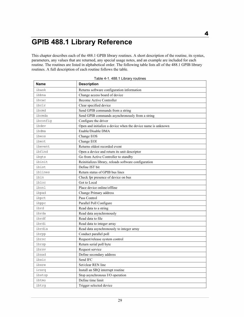
4GPIB 488.1 Library Reference This chapter describes each of the 488.1 GPIB library routines. A short description of the routine, its syntax, parameters, any values that are returned, any special usage notes, and an example are included for each routine. The routines are listed in alphabetical order. The following table lists all of the 488.1 GPIB library routines. A full description of each routine follows the table.
Table 4-1. 488.1 Library routines Name Description ibask Returns software configuration information ibbna Change access board of device ibcac Become Active Controller ibclr Clear specified device ibcmd Send GPIB commands from a string ibcmda Send GPIB commands asynchronously from a string ibconfig Configure the driver ibdev Open and initialize a device when the device name is unknown ibdma Enable/Disable DMA ibeos Change EOS ibeot Change EOI ibevent Returns oldest recorded event ibfind Open a device and return its unit descriptor ibgts Go from Active Controller to standby ibinit Reinitializes library, reloads software configuration ibist Define IST bit iblines Return status of GPIB bus lines ibln Check fpr presence of device on bus ibloc Got to Local ibonl Place device online/offline ibpad Change Primary address ibpct Pass Control ibppc Parallel Poll Configure ibrd Read data to a string ibrda Read data asynchronously ibrdf Read data to file ibrdi Read data to integer array ibrdia Read data asynchronously to integer array ibrpp Conduct parallel poll ibrsc Request/release system control ibrsp Return serial poll byte ibrsv Request service ibsad Define secondary address ibsic Send IFC ibsre Set/clear REN line irsrq Install an SRQ interrupt routine ibstop Stop asynchronous I/O operation ibtmo Define time limit ibtrg Trigger selected device
29

GPIB Library Software User's Manual GPIB 488.1 Library Reference
Name Description ibwait Wait for event ibwrt Write data from a string ibwrta Write data asynchronously from a string ibwrtf Write data from file ibwrti Write data from integer array ibwrtia Write data asynchronously
30

GPIB Library Software User's Manual IBASK
IBASK Returns software configuration information.
Syntax BASIC CALL ibask (boarddev%, option%, value%)
C ibask (int boarddev, int option, unsigned int *value)
PASCAL ibask (boarddev:integer; option:integer; var value: integer)
Parameters boarddev A board handle or device handle
option Specifies which configuration item to return; see . Table 4-2
Table 4-2. ibask options
value Current value of specified item returned here
Option Valid for Information returned IbaPAD bd/dev Primary address of board or device IbaSAD bd/dev Secondary address of board or dev IbaTMO bd/dev The current timeout value for I/O commands (refer to ibtmo for a list of
possible values) IbaEOT bd/dev 0 = EOI asserted at end of write
non zero = EOI is not asserted at end of write IbaPPC bd The current parallel poll configuration of the board IbaREADDR dev 0 = Forced re-addressing is disabled
non zero = Forced re-addressing is enabled. Refer to Force re-addressing on page 9.
IbaAUTOPOLL bd 0 = automatic at end of write non zero = automatic serial poll is disabled
IbaCICPROT bd 0 = CIC protocol is disabled non zero = CIC protocol is enabled
IbaIRQ bd IRQ used for interrupts or 0 if disabled IbaSC bd 0 = board is not system controller
non zero = board is system controller IbaSRE bd 0 = do not automatically assert REN line when system controller
non zero = automatically assert REN line when system controller IbaEOSrd bd/dev 0 = ignore EOS char during reads
non zero = terminate read when EOS char is received IbaEOSwrt bd/dev 0 = don’t assert EOI line when EOS char is sent
non zero = assert EOI line whenever EOS char is sent IbaEOScmp bd/dev 0 = 7 bit compare is used when checking for EOS char
non zero = 8 bit compare is used when checking for EOS char IbaEOSchar bd/dev 0 = The current EOS char of board or device IbaPP2 bd 0 = board is in remote parallel poll configuration
non zero = board is in local parallel poll configuration IbaTiming bd Current T1 timing delay 1 = Normal (2 us), 2 = High Speed (500 ns),
3 = Very High Speed (350 ns) IbaDMA bd Low byte = DMA channel, hex 8000 bit indicates DMA enabled
Examples: 0x003 = DMA disabled, set for DMA chan 3 0x8001 = DMA enabled, set for DMA chan 1
IbaSendLLO bd 0 = LLO command is not sent when device is put online non zero = LLO command is sent
31
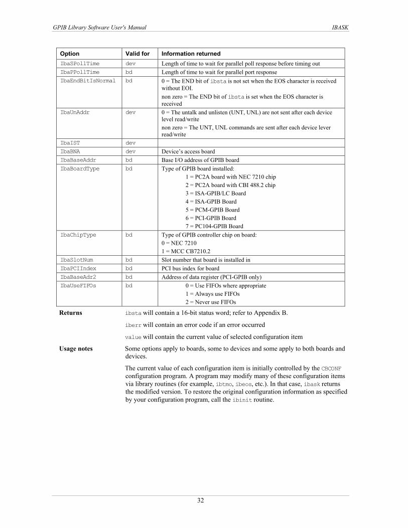
GPIB Library Software User's Manual IBASK
Option Valid for Information returned IbaSPollTime dev Length of time to wait for parallel poll response before timing out IbaPPollTime bd Length of time to wait for parallel port response IbaEndBitIsNormal bd 0 = The END bit of ibsta is not set when the EOS character is received
without EOI. non zero = The END bit of ibsta is set when the EOS character is received
IbaUnAddr dev 0 = The untalk and unlisten (UNT, UNL) are not sent after each device level read/write non zero = The UNT, UNL commands are sent after each device lever read/write
IbaIST dev IbaBNA dev Device’s access board IbaBaseAddr bd Base I/O address of GPIB board IbaBoardType bd Type of GPIB board installed:
1 = PC2A board with NEC 7210 chip 2 = PC2A board with CBI 488.2 chip 3 = ISA-GPIB/LC Board 4 = ISA-GPIB Board 5 = PCM-GPIB Board 6 = PCI-GPIB Board 7 = PC104-GPIB Board
IbaChipType bd Type of GPIB controller chip on board: 0 = NEC 7210 1 = MCC CB7210.2
IbaSlotNum bd Slot number that board is installed in IbaPCIIndex bd PCI bus index for board IbaBaseAdr2 bd Address of data register (PCI-GPIB only) IbaUseFIFOs bd 0 = Use FIFOs where appropriate
1 = Always use FIFOs 2 = Never use FIFOs
Returns ibsta will contain a 16-bit status word; refer to Appendix B.
iberr will contain an error code if an error occurred
value will contain the current value of selected configuration item
Usage notes Some options apply to boards, some to devices and some apply to both boards and devices.
The current value of each configuration item is initially controlled by the CBCONF configuration program. A program may modify many of these configuration items via library routines (for example, ibtmo, ibeos, etc.). In that case, ibask returns the modified version. To restore the original configuration information as specified by your configuration program, call the ibinit routine.
32

GPIB Library Software User's Manual IBASK
Example Returns the primary address of the device named "VoltMeter".
BASIC CALL ibfind (“VoltMeter”, dev%)
CALL ibask (dev%, IbaPAD, address%)
C int dev, address;
dev = ibfind (“Voltmeter”);
ibask (dev, IbaPAD, &address);
PASCAL var dev: integer;
address: integer;
begin
dev := ibfind (“Voltmeter”);
ibask (dev, IbaPAD, address);
33

GPIB Library Software User's Manual IBBNA
IBBNA Purpose Allows you to re-assign a device to another GPIB interface board.
Syntax BASIC CALL ibbna (device%, boardname$)
C ibbna (int device, char boardname[])
PASCAL ibbna (device:integer; varboardname:string)
Parameters device is an integer containing the device handle
boardname is the name of the new board to be assigned the device
Returns ibsta will contain a 16-bit status word; refer to Appendix B.
iberr will contain an error code if an error occurred
Usage Notes This routine changes the board assignment made during the configuration process. The assigned board is used for all subsequent operations involving the specified device until:
ibbna is called again ibonl or ibinit is called the sytem is restarted
Example Use ibfind to return the unit descriptor 5 ("DEV5"), a DMM, into the variable dmm. The DMM is then associated with the GPIB board "GPIB1."
BASIC CALL ibfind(“DEV5”), dmm%)
CALL ibbna (dmm%, “GPIB1”)
C int dmm;
dmm = ibfind (“DEV5”);
ibbna (dmm, “GPIB1”);
PASCAL var
dmm: integer;
begin
dmm := ibfind(‘DEV5’);
ibbna (dmm, ‘GPIB1’);
34
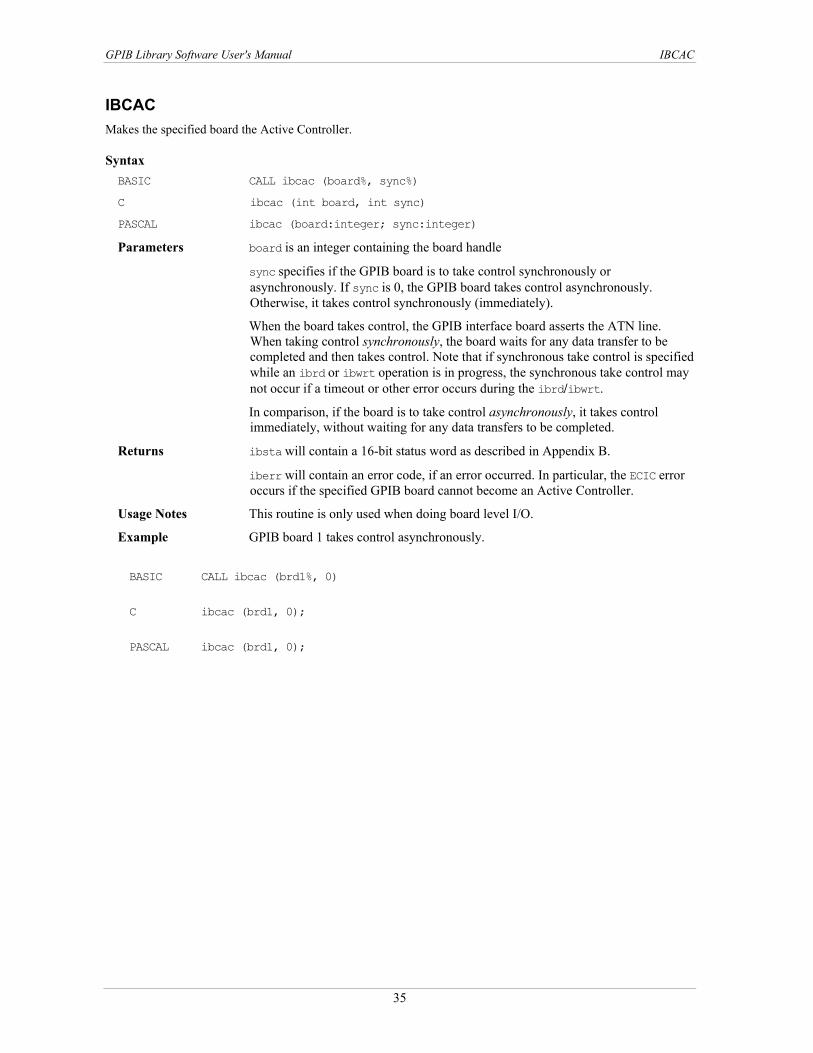
GPIB Library Software User's Manual IBCAC
IBCAC Makes the specified board the Active Controller.
Syntax BASIC CALL ibcac (board%, sync%)
C ibcac (int board, int sync)
PASCAL ibcac (board:integer; sync:integer)
Parameters board is an integer containing the board handle
sync specifies if the GPIB board is to take control synchronously or asynchronously. If sync is 0, the GPIB board takes control asynchronously. Otherwise, it takes control synchronously (immediately).
When the board takes control, the GPIB interface board asserts the ATN line. When taking control synchronously, the board waits for any data transfer to be completed and then takes control. Note that if synchronous take control is specified while an ibrd or ibwrt operation is in progress, the synchronous take control may not occur if a timeout or other error occurs during the ibrd/ibwrt.
In comparison, if the board is to take control asynchronously, it takes control immediately, without waiting for any data transfers to be completed.
Returns ibsta will contain a 16-bit status word as described in Appendix B.
iberr will contain an error code, if an error occurred. In particular, the ECIC error occurs if the specified GPIB board cannot become an Active Controller.
Usage Notes This routine is only used when doing board level I/O.
Example GPIB board 1 takes control asynchronously.
BASIC CALL ibcac (brd1%, 0)
C ibcac (brd1, 0);
PASCAL ibcac (brd1, 0);
35
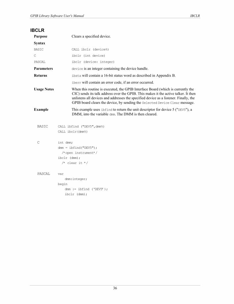
GPIB Library Software User's Manual IBCLR
IBCLR Purpose Clears a specified device.
Syntax BASIC CALL ibclr (device%)
C ibclr (int device)
PASCAL ibclr (device: integer)
Parameters device is an integer containing the device handle.
Returns ibsta will contain a 16-bit status word as described in Appendix B.
iberr will contain an error code, if an error occurred.
Usage Notes When this routine is executed, the GPIB Interface Board (which is currently the CIC) sends its talk address over the GPIB. This makes it the active talker. It then unlistens all devices and addresses the specified device as a listener. Finally, the GPIB board clears the device, by sending the Selected Device Clear message.
Example This example uses ibfind to return the unit descriptor for device 5 ("DEV5"), a DMM, into the variable dmm. The DMM is then cleared.
BASIC CALL ibfind ("DEV5",dmm%)
CALL ibclr(dmm%)
C int dmm;
dmm = ibfind("DEV5");
/*open instrument*/
ibclr (dmm);
/* clear it */
PASCAL var
dmm:integer;
begin
dmm := ibfind (‘DEV5’);
ibclr (dmm);
36

GPIB Library Software User's Manual IBCMD
IBCMD Purpose Sends GPIB commands.
Syntax BASIC CALL ibcmd (board%, cmnd$)
C ibcmd (int board, char cmnd[], long bytecount)
PASCAL ibcmd (board:integer; command:string; bytecount:Longint)
Parameters board is an integer containing the board handle.
cmnd is the command string to be sent. This string is comprised of GPIB multiline commands. These commands are listed in Appendix A.
bytecount is the number of command bytes to be transferred.
Returns ibsta will contain a 16-bit status word as described in Appendix B. iberr will contain an error code, if an error occurred. ibcnt, ibcntl will contain the number of bytes that were read. ibcnt is a 16-bit integer. ibcntl is a 32-bit integer. If the requested count was greater than 64 K, use ibcntl instead of ibcnt.
Usage Notes This routine passes only GPIB commands. It cannot be used to transmit programming instructions (data) to devices. Use the ibrd and ibwrt routines for this purpose.
This routine terminates when any one of the following takes place: Commands transfer is successfully completed. An error occurs A timeout occurs A Take Control (TCT) command is sent The system controller asserts the IFC (Interface Clear) line.
If your application must perform other functions while processing the GPIB command(s), use ibcmda.
Example This example prepares the board to talk and addresses three devices (at addresses 8, 9, and 10) to listen.
BASIC command$ = "?_@()*" 'UNL UNT MTA0 MLA8 MLA9 MLA10
CALL ibcmd (board%, command$)
C char *command;
command = "\0x3f\0x5f\0x40\0x28\0x29\0x2a"
ibcmd (board, command, 6);
PASCAL var
board:integer;
command: string;
bytecount: Longint;
begin
command := ‘#63#95#64#40#41#42’
ibcmd (board, command, 6);
37

GPIB Library Software User's Manual IBCMDA
IBCMDA Purpose Transfers GPIB commands asynchronously from a string.
Syntax BASIC CALL ibcmda (board%, cmnd$)
C ibcmda (int board, char cmnd[], long bytecount)
PASCAL ibcmda (board:integer; command:string; bytecount:Longint)
Parameters board is an integer containing the board handle.
cmnd is thecommand string to be sent. This string is comprised of GPIB multiline commands.These commands are listed in Appendix A.
bytecount is the number of command bytes to be transferred. Note that in C, although this parameter is of type long, integer values and variables can also be passed.
Returns ibsta will contain a 16-bit status word as described in Appendix B.
iberr will contain an error code, if an error occurred. An ECIC error is generated if the GPIB Interface Board specified is not the Active Controller. If no listening devices are found, the ENOL error is returned.
ibcnt, ibcntl will contain the number of bytes tht were read. ibcnt is a 16-bit integer. ibcntl is a 32-bit integer. If the requested count was greater than 64 K, use ibcntl instead of ibcnt.
Usage Notes This routine is seldom used in typical GPIB applications. The only reason to use asynchronous commands is to free up the machine during lengthy operations. GPIB commands are rarely longer then a half dozen bytes; thus, in most cases, you can use ibcmd instead of ibcmda.
This routine passes only commands. It is not used to transmit programming instructions (data) to devices. Use the ibrd/ibwrt routines for this purpose.
This routine terminates when any one of the following takes place: Commands transfer is successfully completed An error occurs A timeout occurs A Take Control (TCT) command is sent The system controller asserts the IFC (Interface Clear) line.
The specified GPIB Interface Board remains the Active Controller of the GPIB bus after this routine has completed, even if it was not the Active Controller before the routine was called.
Remember that once an asynchronous I/O call has begun, any further calls to a library routine (except for ibwait and those functions which do not specify a device or GPIB Interface Board) cannot be executed until the I/O has finished and the GPIB driver and the application have been re-synchronized. This is accomplished by calling one of the following:
ibwait (include CMPL in the mask) The driver and application are synchronized.
ibstop The asynchronous I/O is canceled, and the driver and application are synchronized.
ibonl The asynchronous I/O is canceled, the interface has been reset, and the driver and application are synchronized.
Re-synchronization is successful if a CMPL is returned to ibsta. See Appendix B for further information.
38

GPIB Library Software User's Manual IBCMDA
Example This example prepares the board to talk and addresses three devices (at addresses 8, 9, and 10) to listen. ibcmda executes in the background and the program continues into the WHILE loop. This loop calls ibwait to update ibsta and checks ibsta to see if ibcmda has completed or an error has occurred. The program may do anything within the WHILE loop except make other GPIB I/O calls.
BASIC Command$ = "?_@()*" 'UNL UNT MTA0 MLA8 MLA9 MLA10
CALL ibcmda (board%, command$)
WHILE (ibsta% AND CMPL+EERR) = 0
' Check for complete or error
CALL ibwait (board%, 0) ' This updates ibsta
WEND
C char command[] = "\0x3f\0x5f\0x40\0x28\0x29\0x2a"
ibcmda (board, command, 6);
while ( (ibsta & CMPL+EERR) == 0)
ibwait (board, 0);
PASCAL var
command:string;
begin
command := ‘#63#95#64#40#41#42’;
ibcmda (board, command, 6);
while ( (ibsta & CMPL+EERR) = 0)
ibwait (board, 0);
39

GPIB Library Software User's Manual IBCONFIG
IBCONFIG Purpose Changes configuration parameters.
Syntax BASIC CALL ibconfig (boarddev%, option%, value%)
C ibconfig (int boarddev, unsigned int option, unsigned int value)
PASCAL ibconfig (boarddev:integer; option:integer; value:integer)
Parameters boarddev is an integer containing either a board handle or device handle
option is a number which represents the configuration option to be changed. See . Table 4-3
Table 4-3. ibconfig options
value is the new configuration option value. Allowed values differ according to the option being programmed.
Option Valid for Description IbcPAD bd or
dev New Primary Address. Available primary addresses range from 0 to 30. value can be from 0 to 30 decimal. (See ibpad.)
IbcSAD bd or dev
New Secondary Address. There are 31 secondary addresses available. value can be 0 or from 96 to 126 decimal. (See ibsad.)
IbcTMO bd or dev
Timeout Value. The approximate time that I/O functions take before a timeout occurs. value is a number from 0 to 15 which corresponds to timeout values ranging from 10 usec to 100 sec. (See ibtmo)
IbcEOT bd or dev
Enable/disable END message. If this option is enabled, the EOI line is asserted when the last byte of data is sent. If value = 0, then the EOI line is not asserted. If value is non zero, the EOI line is asserted.
IbcPPC Parallel Poll Configure. Redefines the parallel poll configuration bytes. value can be 0, or from 96 to 126 decimal.
IbcREADDR dev Forced re-addressing. If value = 0, forced re-addressing is disabled non zero = Forced re-addressing is enabled. Refer to the device option "Force re-addressing" on page 9.
IbcAUTOPOLL bd Enable/Disable Automatic Serial Polling. If value is 0, then Automatic Serial Polling is disabled. Otherwise, it is enabled.
IbcCICPROT CIC Protocol. If value is 0, then CIC Protocol is not used. Otherwise, CIC Protocol is used.
IbcIRQ bd Enable/Disable Hardware Interrupts. If value is 0, then hardware interrupts are disabled, otherwise value specifies the IRQ level the board uses to generate interrupts.
IbcSC bd Request/Release System Control. If value is 0, the board is not able to support routines requiring system controller capability. If value is non-zero, the board can support routines requiring system controller capability.
IbcSRE bd Assert/Unassert REN. If value is 0, the REN line is unasserted. Otherwise, the REN line is asserted.
IbcEOSrd bd or dev
Recognize EOS. If value is non-zero, a read is terminated when the End-Of-String (EOS) character is detected. Otherwise, EOS detection is disabled.
IbcEOSwrt bd or dev
Assert EOI. If value is non-zero, then EOI is asserted when the EOS character is sent. Otherwise, EOI is not asserted.
IbcEOScmp bd or dev
7/8-bit Comparison. If value is zero, compare the low-order 7 bits of the EOS character. Otherwise, compare 8-bits.
40

GPIB Library Software User's Manual IBCONFIG
Option Valid for Description IbcEOSchar bd or
dev End-Of-String (EOS) Character. value is the new EOS character. value can be any 8-bit value
IbcPP2 Parallel Poll Remote/Local. If value is zero, then the GPIB Interface Board is remotely configured for a parallel poll by an external Controller. Otherwise, the GPIB interface board accepts parallel poll configuration commands from your application program.
IbcTIMING bd Handshake Timing. If value is 1, normal timing (> 2 *sec.) is used. If value is 2, high-speed timing (> 500 nsec.) is used. If value is 3, very high-speed timing (> 350 nsec.) is used.
IbcDMA bd Enable/Disable DMA. If value is zero, DMA transfers are disabled, otherwise value specifies the DMA channel that the board uses.
IbcSendLLO bd Send Local Lockout. If value is 0, LLO command is not sent when device is put online; non zero = LLO command is sent
IbcBaseAddress bd Base address that board is configured for IbcBoardType bd Type of GPIB Board being used. value =
1: PC2A with NEC 7210 2: PC2A board with the MCC CB7210.2 chip 3: ISA-GPIB/LC 4: ISA-GPIB 5: PCM-GPIB 6: PCI-GPIB 7: PC104-GPIB
IbcSPollTime bd or dev
Serial Poll Timeout. value ranges from 0 to 17 specify timeouts of 10 µsecs to 1000 secs. Refer to "Timeout codes" on page 77.
IbcEndBitIsNormal bd or dev
If set, causes END status to be set on receipt of EOS.
IbcPPollTime bd Parallel Poll Timeout. values ranges from 0 to 17 specify timeouts of 10 µsecs to 1000 secs. Refer to "Timeout codes" on page 77.
IbcUnAddr dev If value is 0, the untalk and unlisten (UNT, UNL) are not sent after each device level read/write; non zero = the UNT, UNL commands are sent after each device lever read/write
Table 4-5
Table 4-5
Returns ibsta will contain a 16-bit status word as described in Appendix B.
iberr will contain an error code, if an error occurred.
Usage Notes None.
Example This example illustrates how to change the timeout value for GPIB Interface Board 1 to 300 msec.
BASIC CALL ibfind ("gpib1", device%)
CALL ibconfig (device%, IbcTMO, 10)
C int device;
device = ibfind ("gpib1");
ibconfig (device, IbcTMO, 10);
PASCAL var
device:integer;
begin
device := ibfind (‘gpib1’);
ibconfig (device, IbcTMO, 10);
41

GPIB Library Software User's Manual IBDEV
IBDEV Purpose Obtains a device handle for a device whose name is unknown. It opens and
initializes the device with the configuration given.
Syntax BASIC CALL ibdev (boardindex%, pad%, sad%, timeout%, eot%, eos%, device%)
C device = ibdev (int boardindex, int pad, int sad, int timeout, int eot, int eos)
PASCAL device:= bdev(boardindex:Integer;pad:Integer; sad:Integer;timeout:Integer;eot:Integer;eos:Integer)
Parameters boardindex identifies the GPIB Interface Board the device descriptor is associated with - index in the range 0 to (total number of boards - 1 ).
pad is the primary address of the device. Available addresses range from 0 to 30.
sad is the secondary address of the device. There are 31 secondary addresses available. value can be 0, or from 96 to 126 decimal; see Appendix A. If 0 is selected, the driver will not expect the device to require a secondary address.
timeout is the tmeout of the device. This is a value from 0 to 17 which corresponds to timeout value ranging from 10 usec to 1000 sec. See Tabl "Timeout codes" on page 77 for a list of timeouts and corresponding values.
e 4-5
eot when writing to a device, eot specifies whether or not to assert EOI with the last data byte. If eot is non-zero, EOI is asserted. If eot is 0, EOI is not asserted.
eos specifies the End-Of-String termination mode to be used when communicating with the device. See "Selecting EOS" on page 45 for a description of special formatting features of this argument.
Table 4-4
Returns device will contain the assigned descriptor or a negative number. If device is a negative number, then an error occurred. Two types of errors can occur:
An EDVR or ENEB error is returned if a device is not available or the board index specifies a non-existent board.
An EARG error is returned if illegal values are given for pad, sad, timeout, eot, eos.
iberr will contain an error code, if an error occurred.
Usage Notes This routine returns the device handle of the first available user-configurable device it finds in the device list. (See the IBCONF program description for more information.) Be sure to open all of the devices (with ibfind) you plan to use before calling ibdev. This guarantees that ibdev will not open a device that you intend to open with ibfind.
It is very important that you disable the device descriptor (use ibonl) when you have finished all operations associated with that device. Otherwise, the device handle is not available for further use with ibdev.
If you use ibdev and ibfind in the same program, you should do the ibfinds on all pre-defined devices prior to calling ibdev.
Example This example opens an available device, associates it with GPIB interface board 1, and assigns it the following device configuration parameters.
primary address = 3 secondary address = 19 (115 decimal, 73 hex) timeout = 10 sec Assert EOI EOS Disabled The new device handle is returned.
42

GPIB Library Software User's Manual IBDEV
BASIC CALL ibdev(1, 3, &H73, 13, 1, 0, device%)
C int device;
device = ibdev(1, 3, 0x73, 13, 1, 0);
PASCAL var
device: integer;
begin
device := ibdev(1, 3, $73, 13, 1, 0);
43

GPIB Library Software User's Manual IBDMA
IBDMA Purpose Enables/Disables DMA.
Syntax BASIC CALL ibdma (board%, dma%)
C ibdma (int board, int dma)
PASCAL ibdma (board:integer; dma:integer)
Parameters board is an integer containing the board handle.
dma is an integer which indicates whether DMA is to be enabled or disabled for the specified GPIB board. If dma is non-zero, all read and write operations between the GPIB board and memory are performed using DMA. Otherwise, programmed I/O is used.
Returns ibsta will contain a 16-bit status word as described in Appendix B.
iberr will contain an error code, if an error occurred. An ECAP error results if you tried to enable DMA operations for a board which does not support DMA operation. If no error occured, the previous value of dma is stored in iberr.
Usage Notes The GPIB Interface Board must have been configured for DMA operations in order for this routine to be executed successfully. (Refer to the IBCONF program.) This routine is useful for alternating between programmed I/O and DMA operations. This call remains in effect until one of the following occurs:
Another ibdma call is made. ibonl or ibfind is called. The program is re-started. The maximum DMA transfer length in Windows is 64 K bytes.
Example This example enables DMA transfers for GPIB Interface Board 1. It assumes that the DMA channel was previously selected in your configuration program.
BASIC CALL ibfind ("gpib1", board%
CALL ibdma (board%, 1)
C int board, ibsta;
board = ibfind ("gpib1");
ibsta = ibdma (board, 1);
PASCAL var board:integer; begin board := ibfind (‘gpib1’); ibsta := ibdma(board, 1);
44
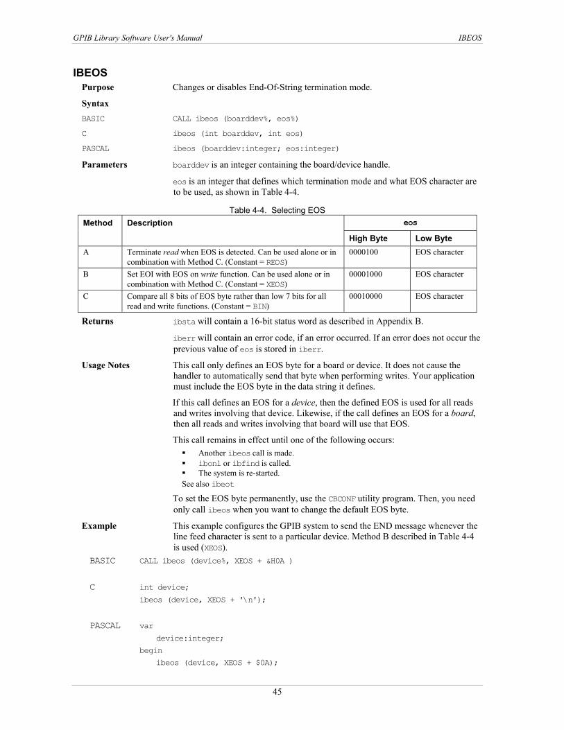
GPIB Library Software User's Manual IBEOS
IBEOS Purpose Changes or disables End-Of-String termination mode.
Syntax BASIC CALL ibeos (boarddev%, eos%)
C ibeos (int boarddev, int eos)
PASCAL ibeos (boarddev:integer; eos:integer)
Parameters boarddev is an integer containing the board/device handle.
eos is an integer that defines which termination mode and what EOS character are to be used, as shown in . Table 4-4
Table 4-4. Selecting EOS
Table 4-4
eos Method Description
High Byte Low Byte A Terminate read when EOS is detected. Can be used alone or in
combination with Method C. (Constant = REOS) 0000100 EOS character
B Set EOI with EOS on write function. Can be used alone or in combination with Method C. (Constant = XEOS)
00001000 EOS character
C Compare all 8 bits of EOS byte rather than low 7 bits for all read and write functions. (Constant = BIN)
00010000 EOS character
Returns ibsta will contain a 16-bit status word as described in Appendix B.
iberr will contain an error code, if an error occurred. If an error does not occur the previous value of eos is stored in iberr.
Usage Notes This call only defines an EOS byte for a board or device. It does not cause the handler to automatically send that byte when performing writes. Your application must include the EOS byte in the data string it defines.
If this call defines an EOS for a device, then the defined EOS is used for all reads and writes involving that device. Likewise, if the call defines an EOS for a board, then all reads and writes involving that board will use that EOS.
This call remains in effect until one of the following occurs: Another ibeos call is made. ibonl or ibfind is called. The system is re-started.
See also ibeot
To set the EOS byte permanently, use the CBCONF utility program. Then, you need only call ibeos when you want to change the default EOS byte.
Example This example configures the GPIB system to send the END message whenever the line feed character is sent to a particular device. Method B described in is used (XEOS).
BASIC CALL ibeos (device%, XEOS + &H0A )
C int device;
ibeos (device, XEOS + '\n');
PASCAL var
device:integer;
begin
ibeos (device, XEOS + $0A);
45

GPIB Library Software User's Manual IBEOT
IBEOT Purpose Enables/Disables assertion of EOI on write operations.
Syntax BASIC CALL ibeot (boarddev%, eot%)
C ibeot (int boarddev, int eot)
PASCAL ibeot (boarddev: integer, eot: integer)
Parameters boarddev is an integer containing the unit descriptor. Here it represents a GPIB Interface Board or a device. This value is obtained by calling the ibfind routine.
eot is an integer which defines whether or not EOI is to be asserted. If eot is non-zero then EOI is asserted automatically when the last byte of the message is sent. If eot is 0, then EOI is not asserted.
Returns ibsta will contain a 16-bit status word as described in Appendix B.
iberr will contain an error code, if an error occurred.
Usage Notes This call is used to temporarily change the default EOT setting.
It is useful to automatically send EOI with the last data byte in situations where variable length data is being sent. When EOI is enabled, you do not need to send an EOS character.
If this call specifies a device, then EOI is asserted/unasserted on all writes to that device. Likewise, if the call specifies a board, then EOI is asserted/unasserted on all writes from that board. To assert EOI with an EOS, use the ibeos routine. This call remains in effect until one of the following occurs:
Another ibeotcall is made. ibonl or ibfind is called. The system is re-started.
See also ibeos Example Assert EOI with last byte of all write operations from GPIB board 1. BASIC CALL ibfind ("gpib1", device%)
CALL ibeot (device%, 1)
C int device;
device = ibfind ("gpib1");
ibeot (device,1);
PASCAL var device:integer; Begin device := ibfind (‘gpib1’); ibeot (device, 1);
46

GPIB Library Software User's Manual IBEVENT
IBEVENT Purpose Returns the oldest recorded event
Syntax BASIC CALL ibevent (board%, event%)
C ibevent (short board, unsigned short *event)
PASCAL ibevent (board:integer; var:event:integer)
Parameters Board is the board handle
Event is the event is returned here.
Returns Ibsta will contain a 16-bit status word described in Appendix B.
Iberr will contain an error code if an error occurred.
Ibcnt will contain the number of events remaining in queue.
event will contain zero.
Usage Notes This function is included for compatibility reasons — the GPIB library does not support an event queue. The return value is always zero.
Example This example returns the next event in the board’s queue
BASIC CALL ibfind (“GPIB0”, board%)
IF (ibsta% AND EEVENT) <> 0 THEN
CALL ibevent (board%, event%)
END IF
C int board, event;
board = ibfind (“GPIB0”);
if (ibsta & EVENT)
ibevent(board, &event);
PASCAL var
board: integer;
event: integer;
begin
board := ibfind (“GPIB0”);
if (ibsta and EVENT) <> 0 then
ibevent (board, event);
47

GPIB Library Software User's Manual IBFIND
IBFIND Purpose Opens a board or device and returns the handle associated with a given name.
Syntax BASIC CALL ibfind (name$, boarddev%)
C boarddev = ibfind (char name[])
PASCAL boarddev := ibfind (var name:nbuf)
Parameters name is the string specifying the board or device name. It must match the configured board or device name specified in your configuration program.
Returns boarddev will contain the device handle associated with the given name. If a negative number is returned, this indicates that the call has failed. This most often happens when the specified name is does not match the default/configured board or device name.
ibsta will contain a 16-bit status word as described in Appendix B.
iberr will contain an error code, if an error occurred.
Usage Notes This call is also opens the device/board and initializes the software parameters to their default configuration settings. See ibonl.
Example This example returns the device handle associated with the device named "DEV5" to the variable dmm. If the device name is not found, the program will jump to an error routine.
BASIC dmm% = ilfind ("DEV5)
If dmm% < 0 Then PrintError C dmm = ibfind("DEV5");
if (dmm < 0) error()
PASCAL dmm := ibfind(‘DEV5’);
if (dmm < 0) error();
48

GPIB Library Software User's Manual IBGTS
IBGTS Purpose Puts an Active Controller in Standby mode.
Syntax BASIC CALL ibgts (board%, handshake%)
C ibgts (int board, int handshake)
PASCAL ibgts (board:integer; handshake : integer)
Parameters board is an integer containing the board handle.
handshake determines whether or not the shadow handshake option is to be activated. If handshake is non-zero, then the GPIB shadow handshake option is activated. This means that the GPIB board shadow handshakes the data transfer as an acceptor and when the END message is detected, the GPIB board enters a Not Ready For Data (NRFD) handshake hold-off state on the GPIB. Thus, the GPIB board participates in the data handshake as an Acceptor without actually reading the data. It monitors the transfers for the END message and holds off subsequent transfers. Using this mechanism, the GPIB board can take control synchronously on a subsequent operation like ibcmd or ibrpp.
If handshake is 0, then no shadow handshake or holdoff is done.
Returns ibsta will contain a 16-bit status word as described in Appendix B.
iberr will contain an error code, if an error occurred. The ECIC error occurs if the board is not an Active Controller.
Usage Notes This call makes the GPIB board go to Controller Standby state and unasserts the ATN line if it is initially the Active Controller. This allows transfers between GPIB devices to occur without the GPIB board's intervention.
Before performing an ibgts with a shadow handshake, use the ibeos function to define/disable EOS character detection.
Example This example uses the ibcmd routine to instruct GPIB board 1 to unlisten all devices (ASCII ?, hex 3F), and then to address a Talker at MTA26 (ASCII Z, hex 5) and a Listener at MLA11 (ASCII +, hex 2B). ibgts is then called to unassert the ATN line and place the GPIB board in Standby mode. This action allows the Talker to send messages to the Listener. Note that the GPIB commands/addresses are coded using printable ASCII characters, for example, "?Z+".
BASIC CALL ibfind ("GPIB1", gpib1%)
CALL ibcmd (gpib1%, "?Z+")
CALL ibgts(gpib1%, 1)
C int gpib1;
gpib1 = ibfind ("GPIB1");
ibcmd (gpib1, "?Z+", 3);
ibgts (gpib1, 1); PASCAL var
gpib1: integer;
begin
gpib1 := ibfind (‘GPIB1’);
ibcmd (gpib1, ‘?Z+’, 3);
ibgts (gpib1, 1);
49

GPIB Library Software User's Manual IBINIT
IBINIT Purpose Re-initialize board, reload configuration information.
Syntax BASIC CALL ibinit (board%)
C ibinit (short board)
PASCAL ibinit (board:integer)
Parameters Board is a board handle.
Returns Ibsta will contain 16-bit status word described in Appendix B.
Iberr will contain an error code if an error occurred.
Usage Notes This routine is useful if you change the configuration (with CBCONF) while a GPIB program is running. If the program calls ibinit, the new configuration is loaded.
This routine can also work around a potentially confusing problem when using the library from Windows. The Windows library is a DLL which is shared between all programs that use it. When the DLL is first called, the system loads it into memory, and the DLL loads configuration information. Normally, when the GPIB program terminates the DLL is unloaded. If the program is run again the whole process is repeated. If more than one program is using the DLL, or when running from some programming environments, the DLL may not be unloaded when the program terminates. In that case, a call to ibinit at the start of the program will force the configuration info to be reloaded.
Example This example reloads the configuration information.
BASIC CALL ibfind (“GPIB0”, board%)
CALL ibinit (board%) C int board;
board = ibfind (“GPIB0”);
ibinit (board); PASCAL var
board: integer;
begin
board := ibfind (‘GPIB0’);
ibinit (board);
50

GPIB Library Software User's Manual IBIST
IBIST Purpose Sets/Clears the IST (Individual Status) Bit of the GPIB board for parallel polls.
Syntax BASIC CALL ibist(board%, statusbit%)
C ibist (int board, int statusbit)
PASCAL ibist (board:integer; statusbit:integer)
Parameters board is an integer containing the board handle.
statusbit indicates whether the IST bit is to be cleared or set. If statusbit is non-zero, then the IST bit is set. Otherwise, if statusbit = 0, the IST bit is cleared.
Returns ibsta will contain a 16-bit status word as described in Appendix B.
iberr will contain an error code, if an error occurred. If an error does not occur, the previous IST value is stored in iberr.
Usage Notes This routine is used when the GPIB Interface is not the Active Controller.
IST should be SET to indicate to the controller that service is required.
Example This example clears GPIB Board 1's IST bit.
BASIC gpib1% = ilfind ("GPIB1")
ibsta% = ilist (gpib1%, 0) C int gpib1;
gpib1 = ibfind ("GPIB1");
ibist (gpib1, 0);
PASCAL var
gpib: integer;
begin
gpib1 = ibfind (‘GPIB1’);
ibist (gpib1, 0);
51

GPIB Library Software User's Manual IBLINES
IBLINES Purpose Returns the status of the GPIB control lines.
Syntax BASIC CALL iblines (board%, clines%)
C iblines (int board, short *clines)
PASCAL iblines (board:integer; clines:integer)
Parameters board is an integer containing the board handle.
Returns clines contain a valid mask and GPIB control line state data. Low-order bytes (bits 0 through 7) contain the mask indicating the capability of the GPIB interface board to sense the status of each GPIB control line. Upper bytes (bits 8 through 15) contain the GPIB control line state information. The pattern of each byte is as follows:
High 15 14 13 12 11 10 9 8 EOI ATN SRQ REN IFC NRFD NDAC DAV Low (Mask) 7 6 5 4 3 2 1 0
To determine if a GPIB control line is asserted, first check the appropriate bit in the lower byte to determine if the line can be monitored (indicated by a 1 in the proper bit position), then check the corresponding bit in the upper byte. If the bit is set (1), the corresponding control line is asserted. If the bit is clear (0), the control line is unasserted.
ibsta will contain a 16-bit status word as described in Appendix B.
iberr will contain an error code, if an error occurred.
Handshake Information: NRFD = Not Ready for Data NDAC = Not Data Accepted DAV = Data Valid
Interface Management: ATN = Attention IFC = Interface Clear REN = Remote Enable SRQ = Service Request EOI = End or Identify
Usage Notes In order for this call to function properly, all devices attached to the GPIB bus must adhere to IEEE-488 specification.
Different Measurement Computing GPIB boards have more or less ability to monitor individual GPIB control lines. The mask bits in clines (bits 0-7) indicate which lines the installed board is capable of monitoring.
Example This example tests the state of the ATN line.
BASIC CONST ATNline% = &H40
CALL iblines (board%, lines%)
IF lines% AND ATNline% = 0 THEN
PRINT "ATN line cannot be monitored by this GPIB board"
ELSE IF (lines% / 256) AND ATNline% = 0 THEN
PRINT "ATN line is not asserted"
ELSE
PRINT "ATN line is asserted"
END IF
52

GPIB Library Software User's Manual IBLINES
C #define ATNLINE = 0x40
int lines;
iblines (board, &lines);
if (lines & ATNLINE == 0)
printf "ATN line can not be monitored by this GPIB board";
else if ( (lines >> 8) & ATNLINE ) == 0)
printf "ATN line is not asserted";
else PASCAL const
ATNLINE := $40
var
lines:integer;
begin
iblines(board, lines);
if lines and ATNLINE = 0 then
writeln ('ATN line can not be monitored by this GPIB board');
else if (lines/256) and ATNLINE = 0 then
writeln ('ATN line not asserted');
else
writeln ('ATN line is asserted');
53
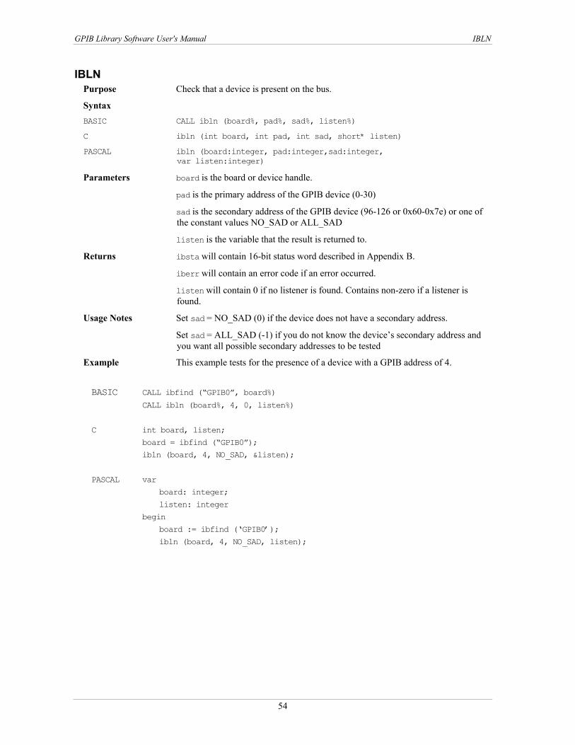
GPIB Library Software User's Manual IBLN
IBLN Purpose Check that a device is present on the bus.
Syntax BASIC CALL ibln (board%, pad%, sad%, listen%)
C ibln (int board, int pad, int sad, short* listen)
PASCAL ibln (board:integer, pad:integer,sad:integer, var listen:integer)
Parameters board is the board or device handle.
pad is the primary address of the GPIB device (0-30)
sad is the secondary address of the GPIB device (96-126 or 0x60-0x7e) or one of the constant values NO_SAD or ALL_SAD
listen is the variable that the result is returned to.
Returns ibsta will contain 16-bit status word described in Appendix B.
iberr will contain an error code if an error occurred.
listen will contain 0 if no listener is found. Contains non-zero if a listener is found.
Usage Notes Set sad = NO_SAD (0) if the device does not have a secondary address.
Set sad = ALL_SAD (-1) if you do not know the device’s secondary address and you want all possible secondary addresses to be tested
Example This example tests for the presence of a device with a GPIB address of 4.
BASIC CALL ibfind (“GPIB0”, board%)
CALL ibln (board%, 4, 0, listen%)
C int board, listen;
board = ibfind (“GPIB0”);
ibln (board, 4, NO_SAD, &listen);
PASCAL var
board: integer;
listen: integer
begin
board := ibfind (‘GPIB0’);
ibln (board, 4, NO_SAD, listen);
54

GPIB Library Software User's Manual IBLOC
IBLOC Purpose Forces the specified board/device to go to local program mode.
Syntax BASIC CALL ibloc (boarddev%)
C ibloc (int boarddev)
PASCAL ibloc (boarddev:integer)
Parameters boarddev is an integer containing the device or board handle.
Returns ibsta will contain a 16-bit status word as described in Appendix B.
iberr will contain an error code, if an error occurred.
Usage Notes This routine is used to place boards or devices temporarily in local mode. If this routine specifies a device, the following GPIB commands are sent:
Talk address of the access board Secondary address of the access board Unlisten (UNL) Listen address of the device Secondary address of the device (as necessary) Go to Local (GTL)
If this routine specifies a board, the board is placed in a local state by sending the Return to Local (RTL) message, if it is not locked in remote mode. The LOK bit of the status word indicates whether the board is in a lockout state. The IBLOC function is used to simulate a front panel RTL switch if the computer is used as an instrument.
Example Return GPIB board 1 to local state.
BASIC CALL ibfind ("GPIB1", gpib1%)
CALL ibloc (gpib1%)
C int gpib1;
gpib1 = ibfind("GPIB1");
ibloc (gpib1);
PASCAL var
gpib: integer;
begin
gpib1 := ibfind(‘GPIB1’);
ibloc (gpib1);
55

GPIB Library Software User's Manual IBONL
IBONL Purpose Enables/Disables a device/interface board for operation.
Syntax BASIC CALL ibonl(boarddev%, online%)
C ibonl (int boarddev, int online)
PASCAL ibonl (boarddev:integer; online:integer)
Parameters boarddev is an integer containing the device/board handle.
online defines whether the device/board is to be enabled/disabled. If online is non-zero, the device/board is enabled for operation (placed on-line). This restores the board/device to its default settings. Otherwise, the board/device is placed off-line.
Returns ibsta will contain a 16-bit status word as described in Appendix B.
iberr will contain an error code, if an error occurred.
Usage Notes When a device is placed off-line, it is in essence "closed". This means that in order to perform any other operations with this device, you will need to re-open it by calling the ibfind or ibdev routine.
Example This example restores the configuration of device 0.
BASIC CALL ibfind ("DEV0", dev0%)
CALL ibonl (dev0%, 1) C int dev0;
dev0 = ibfind ("DEV0");
ibonl (dev0, 1); PASCAL var
dev0: integer;
begin
dev0 := ibfind (‘DEV0’);
ibonl (dev0, 1);
56

GPIB Library Software User's Manual IBPAD
IBPAD Purpose Changes the primary address assigned to a device or interface board.
Syntax BASIC CALL ibpad (boarddev%, address%)
C ibpad (int boarddev, int address)
PASCAL ibpad(boarddev:integer; address:integer)
Parameters boarddev is an integer containing the board or device handle.
address specifies the new primary GPIB address. Valid primary addresses range from 0 to 30 (0 to 1E hex).
Returns ibsta will contain a 16-bit status word as described in Appendix B.
iberr will contain an error code if an error occurred. Contains the previous primary address if no error occurred. EARG error occurs if address is out of range.
Usage Notes This routine temporarily changes the configuration setting. It remains in effect until ibonl or ibfind is called, ibpad is called again, or the system is re-started.
If a device is specified, its talk and listen addresses are assigned on the basis of address. Its Listen Address equals address + 20 hex. Its Talk Address equals address + 40 hex. Thus, if a primary address of 0D hex was specified, the corresponding Listen Address would be 2D hex (MLA 13) and Talk Address would be 4D hex (MTA 13). If a board is specified, the board is assigned the primary addressed defined by address. Refer also to ibsad and ibonl.
Be sure that the address specified agrees with the GPIB address of the device. (Set with hardware switches or by a software program. Refer to the device's documentation for more information.)
Example This example changes the primary GPIB address associated with DVM ("DEV4") to 1C hex.
BASIC CALL ibfind ("DEV4", dvm%) CALL ibpad (dvm%, &H1C) C int dvm; dvm = ibfind ("DEV4"); ibpad (dvm, 0x1C); PASCAL var dvm: integer; begin dvm := ibfind (‘DEV4’); ibpad (dvm, 0x1C);
57

GPIB Library Software User's Manual IBPCT
IBPCT Purpose Passes control to another device.
Syntax BASIC CALL ibpct (device%)
C ibpct (int device)
PASCAL ibpct (device:integer)
Parameters device an integer containing the device handle.
Returns ibsta will contain a 16-bit status word as described in Appendix B.
iberr will contain an error code, if an error occurred.
Usage Notes This makes the specified device the Controller-In-Charge (CIC). The GPIB board goes to the Controller Idle state and releases the ATN line.
The device that control is passed to must have Controller capability.
Example This example makes Device ABCD the Controller-In-Charge.
BASIC CALL ibfind ("ABCD", abcd%)
CALL ibpct(abcd%)
C int abcd;
abcd = ibfind ("ABCD");
ibpct(abcd);
PASCAL var abcd: integer;
begin
abcd := ibfind (‘ABCD’);
ibpct (abcd);
58

GPIB Library Software User's Manual IBPPC
IBPPC Purpose Enables/Disables parallel polling of the specified device.
BASIC CALL ibppc (boarddev%, command%)
C ibppc (int boarddev, int command)
PASCAL ibppc(boarddev:integer; command:integer)
Syntax
Parameters boarddev is the device’s handle. This value is obtained by calling the ibfind routine.
command is a valid parallel poll enable/disable message or 0. If command represents a PPE message, then the device will use that message to respond to a parallel poll. Valid PPE messages range from 60 to 6F hex. The PPE specifies the GPIB data line (DIO through DIO ) on which the device is to respond and whether that line is to be asserted or unasserted.
1 8
7 6 5 4 3 2
The PPE byte is of the format: 1 0
0 1 0 SENSE 1 P2 P1 P0
SENSE indicates the condition under which the data line is to be asserted. The device compares the value of the sense bit to its IST (individual status) bit and responds appropriately. For example, if SENSE = 1, the device will drive the line TRUE if its IST = 1 or FALSE if IST = 0.
P2 - P0 specify which GPIB data line should be used to respond to a parallel poll, as shown below:
Where:
P2 P1 P0 GPIB Data Line 1 1 1 DIO8 1 1 0 DIO7 1 0 1 DIO6 1 0 0 DIO5 0 1 1 DIO4 0 1 0 DIO3 0 0 1 DIO2 0 0 0 DIO1
For example, if the PPE byte 01101011 (hex 6B) is sent, the device will drive DIO4 true if its IST bit = 1, or false if its IST bit = 0.
If command is 0 or represents a PPD (Parallel Poll Disable) message, the current PPE (Parallel Poll Enable) configuration is cancelled. Valid PPD messages range from 70 to 7F hex. The PPD is of a similar format to the PPE byte, for example:
7 6 5 4 3 2 1 0 0 1 1 0 SENSE P2 P1 P0
Returns ibsta will contain a 16-bit status word as described in Appendix B.
iberr will contain an error code, if an error occurred. Contains the previous value of command if no error occurs.
Usage Notes If boarddev specifies a GPIB interface board, this routine sets the board's Local Poll Enable (LPE) message to command.
59

GPIB Library Software User's Manual IBPPC
If boarddev specifies a device, the GPIB Interface Board associated with the device addresses itself as a Talker, unlistens all devices (sends a UNL), addresses the specifed device as a Listener, and sends the PPC command followed by a PPE or PPD command.
Example This example configures device 29 to send DIO7 true if its IST bit = 1.
BASIC dev29% = ilfind ("DEV29")
ibsta% = ilppc (dev29%, &H6B)
C int dev29;
dev29 = ibfind ("DEV29");
ibppc (dev29, 0x6B);
PASCAL var
dev29: integer;
begin
dev29 := ibfind (‘DEV29’);
ibppc (dev29, $6B);
60

GPIB Library Software User's Manual IBRD
IBRD Purpose Reads data from a device/interface board into a string.
Syntax BASIC CALL ibrd (boarddev%, buf$)
C ibrd (int boarddev, char buf[], unsigned long bytecount)
PASCAL ibrd (boarddev:integer, var buf; bytecount: longint)
Parameters boarddev is an integer containing the board or device handle.
buf is the storage buffer for the data. Up to 4 gigabytes-1 (232-1 bytes) can be stored. String size may be limited by the language you are using. Check documentation for your language.
bytecount specifies the maximum number of bytes to read.
Returns ibsta will contain a 16-bit status word as described in Appendix B.
iberr will contain an error code of the first error detected, if an error occurred. An EADR results if the specified GPIB Interface Board is an Active Controller but has not been addressed to listen. An EABO error results if a timeout occurs.
Ibcnt, ibcntl will contain the number of bytes that were read. ibcnt is a 16-bit integer. ibcntl is a 32-bit integer. If the requested count was greater than 64 K, use ibcntl instead of ibcnt.
Usage Notes A read will terminate when one of the following occurs: The allocated buffer becomes full. An error is detected. The time limit is exceeded. A terminator (or EOI) is detected.
If boarddev specifies a device, the specified device is addressed to talk and its associated access board is addressed to listen.
If boarddev specifies a GPIB Interface board, you must have already addressed a device as a talker and the board as a listener. If the board is the Active Controller, it will unassert ATN in order to receive data. This routine leaves the board in that state.
Example This example reads 90 characters of data from DEV5.
BASIC dev5% = ilfind ("DEV5")
rd$ = space$(90)
ibsta% = ilrd (DEV5%, rd$)
C int dev5;
char rd [90];
dev5 = ibfind ("DEV5");
ibrd (dev5, rd, 90); PASCAL var
dev5: integer;
begin
dev5 := ibfind (‘DEV5’);
ibrd (dev5, rd, 90);
61
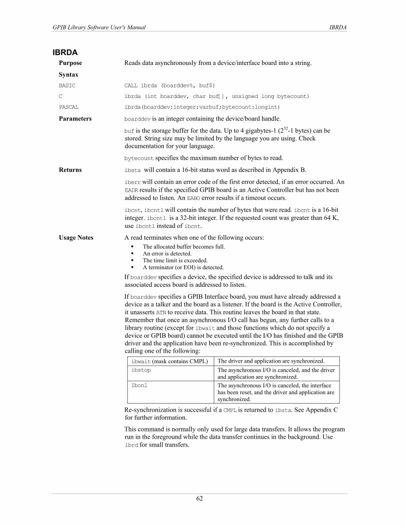
GPIB Library Software User's Manual IBRDA
IBRDA Purpose Reads data asynchronously from a device/interface board into a string.
Syntax BASIC CALL ibrda (boarddev%, buf$)
C ibrda (int boarddev, char buf[], unsigned long bytecount)
PASCAL ibrda(boarddev:integer;varbuf;bytecount:longint)
Parameters boarddev is an integer containing the device/board handle.
buf is the storage buffer for the data. Up to 4 gigabytes-1 (232-1 bytes) can be stored. String size may be limited by the language you are using. Check documentation for your language.
bytecount specifies the maximum number of bytes to read.
Returns ibsta will contain a 16-bit status word as described in Appendix B.
iberr will contain an error code of the first error detected, if an error occurred. An EADR results if the specified GPIB board is an Active Controller but has not been addressed to listen. An EABO error results if a timeout occurs.
ibcnt, ibcntl will contain the number of bytes that were read. ibcnt is a 16-bit integer. ibcntl is a 32-bit integer. If the requested count was greater than 64 K, use ibcntl instead of ibcnt.
Usage Notes A read terminates when one of the following occurs: The allocated buffer becomes full. An error is detected. The time limit is exceeded. A terminator (or EOI) is detected.
If boarddev specifies a device, the specified device is addressed to talk and its associated access board is addressed to listen.
If boarddev specifies a GPIB Interface board, you must have already addressed a device as a talker and the board as a listener. If the board is the Active Controller, it unasserts ATN to receive data. This routine leaves the board in that state. Remember that once an asynchronous I/O call has begun, any further calls to a library routine (except for ibwait and those functions which do not specify a device or GPIB board) cannot be executed until the I/O has finished and the GPIB driver and the application have been re-synchronized. This is accomplished by calling one of the following: ibwait (mask contains CMPL) The driver and application are synchronized. ibstop The asynchronous I/O is canceled, and the driver
and application are synchronized. Ibonl The asynchronous I/O is canceled, the interface
has been reset, and the driver and application are synchronized.
Re-synchronization is successful if a CMPL is returned to ibsta. See Appendix C for further information.
This command is normally only used for large data transfers. It allows the program run in the foreground while the data transfer continues in the background. Use ibrd for small transfers.
62

GPIB Library Software User's Manual IBRDA
Example In this example, ibwrt sends the command "DUMP" to a device. The device responds by sending back a large block of data. ibrda begins a transfer of 5000 bytes in the background and the program continues on into the WHILE loop. The WHILE loop calls ibwait with MASK set to 0 to update IBSTA. The WHILE loop checks IBSTA to see if ibrda has completed, or if an error has occurred. The program may do anything else within the WHILE loop except make other GPIB I/O calls.
BASIC readbuffer = space$(5000)
CALL ibwrt (device%, "DUMP")
CALL ibrda (device%, readbuffer$)
WHILE (ibsta% AND CMPL+EERR) = 0
' Check for complete or error
ibwait (device%, 0)
' Other code may be inserted here
WEND
Note for Basic You cannot read into a zero length string because the library determines the read length from the string length – pre-allocate the string by filling with characters such as spaces.
C char *readbuffer[5000]; ibwrt (device, "DUMP"); ibrda (device, readbuffer, 5000); while ( (ibsta & CMPL+EERR) == 0) ibwait (device, 0) PASCAL type buf = array[1...5000] of char; var readbuffer:buf; begin ibwrt(device, ‘DUMP’); ibrda(device, readbuffer, 5000); while ibsta and (CMPL + EERR) = 0 do IBWAIT (device, 0);
63

GPIB Library Software User's Manual IBRDF
IBRDF Purpose Reads data from the GPIB into a file.
Syntax BASIC CALL ibrdf(boarddev%, filename$)
C ibrdf (int boarddev, char filename [])
PASCAL ibrdf (boarddev:integer; var filename:flbuf)
Parameters boarddev is an integer containing the device/board handle.
filename is the name of the file (up to 250 characters, including drive/path) in which the data is to be stored. Be certain to specify a drive and path if necessary. This file is automatically opened as a binary file. It is created if it does not already exist.
Returns ibsta will contain a 16-bit status word as described in Appendix B.
iberr will contain an error code, if an error occurred. An EFSO error is generated if the file can not be opened, created, found, written to, or closed.
ibcnt, ibcntl will contain the number of bytes that were read. ibcnt is a 16-bit integer. ibcntl is a 32-bit integer. If the requested count was greater than 64 K, use ibcntl instead of ibcnt
Usage Notes A read terminates when one of the following occurs: The allocated buffer becomes full. An error is detected. The time limit is exceeded. A terminator (or EOI) is detected. A DCL or SDC command is received from the Active Controller.
If boarddev specifies a device, the specified device is addressed to talk and its associated access board is addressed to listen.
If boarddev specifies a GPIB Interface board, you must have already addressed a device as a talker and the board as a listener. If the board is the Active Controller, it unasserts ATN in order to receive data. This routine leaves the board in that state.
Example This program sends the command "DUMP" to a device. The device responds by sending data back. ibrdf reads the incoming data and stores it in the file called gpib.dat on the C drive.
BASIC CALL ibwrt (boarddev%, "DUMP")
CALL ibrdf (boarddev%, "c:gpib.dat")
C ibwrt (boarddev, "DUMP");
ibrdf (boarddev, "c:gpib.dat");
PASCAL var boarddev: integer;
begin
ibwrt (boarddev, ’DUMP’)
ibrdf (boarddev, ‘c:gpib.dat’);
64

GPIB Library Software User's Manual IBRDI (QuickBASIC, BASIC only)
IBRDI (QuickBASIC, BASIC only) Purpose Reads data into an integer array.
Syntax BASIC CALL ibrdi(boarddev%, iarr%(), bytecount&)
C Not Supported
PASCAL Not Supported
Parameters boarddev is an integer containing the device/board handle.
iarr is the integer array into which data is to be read.
bytecount specifies the maximum number of bytes to be read.
Returns ibsta will contain a 16-bit status word as described in Appendix B.
iberr will contain an error code of the first error detected, if an error occurred. An EADR results if the specified GPIB Interface Board is and Active Controller but has not been addressed to listen. An EABO errror results if a timeout occurs.
ibcnt, ibcntl will contain the number of bytes that were read. ibcnt is a 16-bit integer. ibcntl is a 32-bit integer. If the requested count was greater than 64 K, use ibcntl instead of ibcnt
Usage Notes As data is read, each byte pair is treated as an integer. In C and PASCAL, ibrd can be used to read both strings and integers.
Example This example reads 90 bytes of data from a device address at MTA 15 (hex 4F, ASCII 0) to GPIB Board 1. The GPIB board's listen address is MLA 1. (hex 21, ASCII !).
BASIC DIM iarr%(45) 'dimension array as 1/2 of byte count
brd1% = ilfind("GPIB1")
ibsta% = ilcmd (brd1%, "?0!", 3)
ibsta% = ilrdi (brd1%, iarr%(), 90)
C Not supported PASCAL Not supported
65
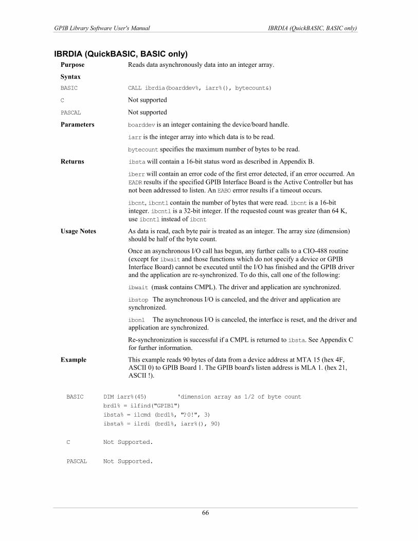
GPIB Library Software User's Manual IBRDIA (QuickBASIC, BASIC only)
IBRDIA (QuickBASIC, BASIC only) Purpose Reads data asynchronously data into an integer array.
Syntax BASIC CALL ibrdia(boarddev%, iarr%(), bytecount&)
C Not supported
PASCAL Not supported
Parameters boarddev is an integer containing the device/board handle.
iarr is the integer array into which data is to be read.
bytecount specifies the maximum number of bytes to be read.
Returns ibsta will contain a 16-bit status word as described in Appendix B.
iberr will contain an error code of the first error detected, if an error occurred. An EADR results if the specified GPIB Interface Board is the Active Controller but has not been addressed to listen. An EABO errror results if a timeout occurs.
ibcnt, ibcntl contain the number of bytes that were read. ibcnt is a 16-bit integer. ibcntl is a 32-bit integer. If the requested count was greater than 64 K, use ibcntl instead of ibcnt
Usage Notes As data is read, each byte pair is treated as an integer. The array size (dimension) should be half of the byte count.
Once an asynchronous I/O call has begun, any further calls to a CIO-488 routine (except for ibwait and those functions which do not specify a device or GPIB Interface Board) cannot be executed until the I/O has finished and the GPIB driver and the application are re-synchronized. To do this, call one of the following:
ibwait (mask contains CMPL). The driver and application are synchronized.
ibstop The asynchronous I/O is canceled, and the driver and application are synchronized.
ibonl The asynchronous I/O is canceled, the interface is reset, and the driver and application are synchronized.
Re-synchronization is successful if a CMPL is returned to ibsta. See Appendix C for further information.
Example This example reads 90 bytes of data from a device address at MTA 15 (hex 4F, ASCII 0) to GPIB Board 1. The GPIB board's listen address is MLA 1. (hex 21, ASCII !).
BASIC DIM iarr%(45) 'dimension array as 1/2 of byte count
brd1% = ilfind("GPIB1")
ibsta% = ilcmd (brd1%, "?0!", 3)
ibsta% = ilrdi (brd1%, iarr%(), 90)
C Not Supported.
PASCAL Not Supported.
66

GPIB Library Software User's Manual IBRPP
IBRPP Purpose Initiates a parallel poll.
Syntax BASIC CALL ibrpp(boarddev%, command%)
C ibrpp (int boarddev, char *command) PASCAL ibrpp (boarddev:integer, var command:byte)
Parameters device an integer containing device or board handle.
Returns command will contain the response to the parallel poll.
ibsta will contain a 16-bit status word as described in Appendix B.
iberr will contain an error code, if an error occurred.
Usage Notes If this routine is called specifying a GPIB Interface Board, the board parallel polls all previously configured devices. If the routine is called specifying a device, the GPIB Interface board associated with the device conducts the parallel poll. Note that if the GPIB Interface Board to conduct the parallel poll is not the Controller-In-Charge, an ECIC error is generated.
Before executing a parallel poll, the ibppc function should configure the connected devices with ibppc to specify how they should respond to the poll.
Example This program configures two devices for a parallel poll. It then conducts the poll. It is assumed that voltmeter and scope have already been set by opening the devices with an ibfind and board has been set by opening the board with an ibfind.
Both devices indicate that they want service by setting their first bit to 1. The first ibppc specifies that the first device (voltmeter%) should drive the DIO1 line high when its first line goes high. The second ibppc specifies that the second device (scope%) should drive the DIO2 line high when its first bit goes high. The ibrpp conducts the poll and checks DIO1 and DIO2 to see if either device is requesting service.
BASIC CALL ibppc (voltmeter%, &H68)
CALL ibppc (scope%, &H69)
CALL ibrpp (board%, pollbyte%)
IF pollbyte% AND 1 <> 0 THEN
PRINT "Volt meter is requesting service"
IF pollbyte% AND 2 <> 0 THEN
PRINT "Oscilloscope is requesting service"
C int voltmeter, scope, board, pollbyte;
ibppc (voltmeter, 0x68)
ibppc (scope, 0x69)
ibrpp (board, &pollbyte)
if (pollbyte & 1)
printf "Volt meter is requesting service"
if (pollbyte & 2)
printf "Oscilloscope is requesting service"
67
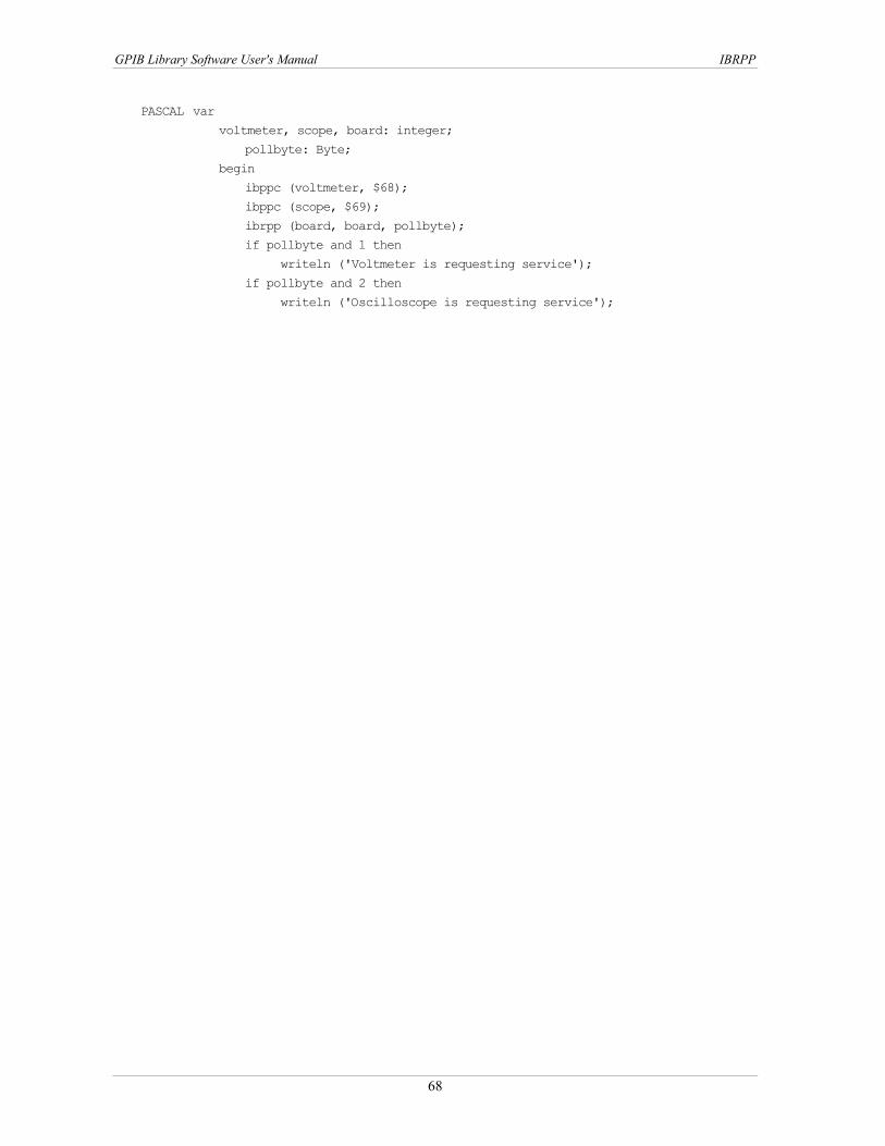
GPIB Library Software User's Manual IBRPP
PASCAL var voltmeter, scope, board: integer;
pollbyte: Byte;
begin
ibppc (voltmeter, $68);
ibppc (scope, $69);
ibrpp (board, board, pollbyte);
if pollbyte and 1 then
writeln ('Voltmeter is requesting service');
if pollbyte and 2 then
writeln ('Oscilloscope is requesting service');
68
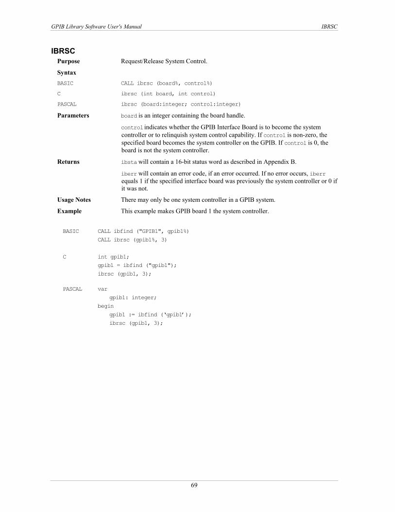
GPIB Library Software User's Manual IBRSC
IBRSC Purpose Request/Release System Control.
Syntax BASIC CALL ibrsc (board%, control%)
C ibrsc (int board, int control) PASCAL ibrsc (board:integer; control:integer)
Parameters board is an integer containing the board handle.
control indicates whether the GPIB Interface Board is to become the system controller or to relinquish system control capability. If control is non-zero, the specified board becomes the system controller on the GPIB. If control is 0, the board is not the system controller.
Returns ibsta will contain a 16-bit status word as described in Appendix B.
iberr will contain an error code, if an error occurred. If no error occurs, iberr equals 1 if the specified interface board was previously the system controller or 0 if it was not.
Usage Notes There may only be one system controller in a GPIB system.
Example This example makes GPIB board 1 the system controller.
BASIC CALL ibfind ("GPIB1", gpib1%)
CALL ibrsc (gpib1%, 3)
C int gpib1;
gpib1 = ibfind ("gpib1");
ibrsc (gpib1, 3);
PASCAL var
gpib1: integer;
begin
gpib1 := ibfind (‘gpib1’);
ibrsc (gpib1, 3);
69

GPIB Library Software User's Manual IBRSP
IBRSP Purpose Serial polls a device.
Syntax BASIC CALL ibrsp(device%, serialpollbyte%)
C ibrsp (int device, char *serialpollbyte) PASCAL ibrsp (device:integer; var:serialpollbyte:byte)
Parameters device is an integer containing the device handle.
Returns serialpollbyte will contain the serial poll response byte of the device. The serial poll response byte is device-specific with the exception of bit 6. If bit 6 (hex 40) is set, then the device is requesting service. Consult the device's documentation for more information.
ibsta will contain a 16-bit status word as described in Appendix B.
iberr will contain an error code, if an error occurred.
Usage Notes If the automatic serial polling feature is enabled, the specified device may have been automatically polled previously. If it has been polled and a positive response was obtained, the RQS bit of ibsta is set on that device. In this case ibrsp returns the previously acquired status byte. If the RQS bit of ibsta is not set during an automatic poll, it serial polls the device. This routine is used to serial poll one device, and obtain its status byte or to obtain a previously stored status byte. If bit 6 (the hex 40 bit) of the response is set, the device is requesting service.
When a serial poll occurs, the following sequence of events happens. The board sends an UNL (unlisten) command. It then addresses itself as a listener and sends a SPE (Serial Poll Enable) Byte. It then addresses a device as a talker. The board then reads the serial poll response byte from the device. The board then sends a serial poll disable (SPD) and untalks and unlistens all devices.
Example Returns the serial response byte (into serialpollbyte) of device 1.
BASIC CALL ibfind ("DEVICE1", dev1%) CALL ibrsp (dev1%, serialpollbyte%) C int dev1; char serialpollbyte; dev1 = ibfind ("device1"); ibrsp (dev1, &serialpollbyte); PASCAL var dev1: integer; serialpollbyte: Byte; begin dev1 := ibfind (‘device1’); ibrsp (dev1, serialpollbyte);
70

GPIB Library Software User's Manual IBRSV
IBRSV Purpose Changes the serial poll response byte of the GPIB board or device.
Syntax BASIC CALL ibrsv (boarddev%, statusbyte%)
C ibrsv (int boarddev, int statusbyte) PASCAL ibrsv (boarddev:integer; statusbyte:integer)
Parameters boarddev is an integer containing the board handle.
statusbyte represents the serial poll response byte of the GPIB Interface Board. The serial poll response byte is system-specific, with the exception of bit 6 (hex 40). If bit 6 (hex 40) is set, then the SRQ line is asserted to indicate to the Controller-In-Charge that the board is requesting service.
Returns ibsta will contain a 16-bit status word as described in Appendix B.
iberr will contain an error code, if an error occurred. If no error occurs, iberr will contain the previous value of statusbyte.
Usage Notes This routine is used when the specified GPIB Interface Board is not the Controller-In-Charge. It can be used to request service (set bit 6 of the serial response byte) from the Controller-In-Charge or to change the value of GPIB Interface Board's serial poll response byte.
Example This example sets the GPIB Interface Board 1 serial poll status byte to 41 hex (assert SRQ) which indicates that the board requires service.
BASIC CALL ibfind ("GPIB1", gpib1%)
CALL ibrsv (gpib1%, &H41)
C int gpib1;
gpib1 = ibfind ("gpib1");
ibrsv (gpib1, 0x41);
PASCAL var
gpib1: integer;
begin
gpib1 = ibfind (‘gpbi1’); ibrsv (gpib1, $41);
71
GPIB Library Software User's Manual IBSAD
IBSAD Purpose Assigns/unassigns a secondary address to a board or device.
Syntax BASIC CALL ibsad (boarddev%, address%)
C ibsad (int boarddev, int address) PASCAL ibsad(boarddev:integer; address:integer)
Parameters boarddev is an integer containing device or board handle.
address represents the secondary address. If address = 0 or address = 7F hex, secondary addressing is disabled. If address is a legal secondary address (60 to 7E hex), the new secondary address is temporarily assigned to the board/device. The new secondary address is used until it is either redefined by calling ibsad again, the device/board is re-initialized by callling ibfind or ibonl, or the program is restarted.
Returns ibsta will contain a 16-bit status word as described in Appendix B.
iberr will contain an error code, if an error occurs. Contains the previously assigned secondary address if no error occurs.
Usage Notes See also ibpad.
Example This example assigns the secondary address 7 (MSA7, hex 67) to device 5.
BASIC CALL ibfind ("DEVICE5", dev5%)
CALL ibsad (dev5%, &H67)
C int dev5;
dev5 = ibfind ("DEVICE5");
ibsad (dev5, 0x67);
PASCAL var
dev5: integer;
begin
dev5 := ibfind (‘DEVICE5’);
ibsad (dev5, $67);
72
GPIB Library Software User's Manual IBSIC
IBSIC Purpose Asserts IFC (Interface Clear) signal. This re-initializes the GPIB system.
Syntax BASIC CALL ibsic (board%)
C ibsic (int board) PASCAL ibsic (board:integer)
Parameters board is an integer containing the board handle.
Returns ibsta will contain a 16-bit status word as described in Appendix B.
iberr will contain an error code, if an error occurred. The ESAC error is generated if the specified GPIB Interface Board is not the system controller.
Usage Notes This routine can only be used if the specified GPIB board is the system controller. When the routine is executed, the GPIB interface board asserts the IFC (Interface Clear) signal for at least 100 µsec. This action results in the system controller regaining control of the GPIB (for example, becoming the Controller-In-Charge). When IFC line is asserted, all GPIB interface functions of the bus devices are reset.
Example This example resets the GPIB bus associated with the specified GPIB Interface Board and makes that board Controller-In-Charge.
BASIC CALL ibfind ("GPIB1", gpib1%)
CALL ibsic (gpib1%)
C int gpib1;
gpib1 = ibfind("GPIB1");
ibsic (gpib1);
PASCAL var
gpib1: integer;
begin
gpib1 := ibfind (‘GPIB1’);
ibsic (gpib1);
73

GPIB Library Software User's Manual IBSRE
IBSRE Purpose Asserts/Unasserts the REN (Remote Enable) line.
Syntax BASIC CALL ibsre (board%, ren%)
C ibsre (int board, int ren) PASCAL ibsre (board:integer; ren:integer)
Parameters board is an integer containing the board handle.
ren specifies whether the REN line is to be asserted or unasserted. If ren is zero, the REN line is unasserted. Otherwise, the REN line is asserted.
Returns ibsta will contain a 16-bit status word as described in Appendix B.
iberr will contain an error code, if an error occurred. The ESAC error is generated if the specified GPIB interface board is not the system controller. Contains the previous REN state if no error occurs.
Usage Notes This routine can only be used if the specified GPIB interface board is the system controller.
Even though the REN line is asserted, the device(s) is not put into remote state until is addressed to listen by the Active Controller. When the REN line is unasserted, all devices return to local control.
Example This example puts the device at MLA 12 (2C hex, ASCII ,) and associated with GPIB Interface Board 1 in remote mode.
BASIC CALL ibfind ("GPIB1", gpib%)
CALL ibsre (gpib1%, 2) ' You can use any non-zero value
CALL ibcmd (gpib1%, ",") C int gpib1:
gpib1 = ibfind ("GPIB1");
ibsre (gpib1, 2); /* Use any non-zero value */
ibcmd (gpib1,",", 1);
PASCAL var
gpib1: integer;
begin
gpib1 := ibfind (‘GPIB1’); ibsre (gpib1, 2); ibcmd (gpib1, ",", 1);
74

GPIB Library Software User's Manual IBSRQ (C only)
IBSRQ (C only) Purpose Defines the user-written service routine to be executed upon detection of SRQ.
Syntax
BASIC Not applicable C ibsrq (void (far *func) (void) )
PASCAL Not applicable
Parameters func is the procedure to call whenever the SRQI bit is set (= 1) in ibsta. If func = NULL, then SRQ servicing is disabled.
Returns ibsta will contain a 16-bit status word as described in Appendix B.
iberr will contain an error code, if an error occurred.
Usage Notes Automatic serial polling must be disabled in order to use this routine.
The SRQI bit in ibsta is checked after each call to the handler is made. If the SRQI bit = 1, then the func routine is called before control is returned to the application program.
Example Define the routine to be called when SRQI is set (=1).
BASIC Not Applicable C int plotter;
main () { int gpib1 = ibfind ("gpib1"); /*disable autopolling */ ibconfig (gpib1, ibcAUTOPOLL, 0); plotter = ibfind ("DEVICE5"); ibsrq (srqroutine); }
void far srqroutine () { char spr; ibrsp (plotter, &spr); /* analyze spr here */ }
PASCAL Not Applicable
75

GPIB Library Software User's Manual IBSTOP
IBSTOP Purpose Terminate an asynchronous operation.
Syntax BASIC CALL ibstop (boarddev%) C ibstop (int boarddev)
PASCAL ibstop (boarddev:integer)
Parameters boarddev is an integer containing the device or board handle.
Returns ibsta will contain a 16-bit status word as described in "Appendix B. If an operation is terminated, the EERR bit is set.
iberr will contain an error code, if an error occurred. If an operation is terminated, an EABO error is returned.
Usage Notes If a device is specified, all unfinished asynchronous operations (read, write, or command) associated with that device is stopped. If a GPIB Interface Board is specified, all unfinished asynchronous operations associated with that board is stopped. Once the operation(s) have been terminated, the application is resynchronized with the driver.
Example This example starts a background write command and then immediately stops it.
BASIC CALL ibfind ("DEV2", dev%)
CALL ibwrta (dev%, "datafile") CALL ibstop (dev%)
C int dev; dev = ibfind ("DEV2"); ibwrta(dev, "datafile"); ibstop (dev);
PASCAL var
dev: integer; begin dev:= ibfind (‘DEV2’); ibwrta (dev, 'datafile'); ibstop (dev);
76

GPIB Library Software User's Manual IBTMO
IBTMO Purpose Changes timeout value.
Syntax BASIC CALL ibtmo (boarddev%, timeout%) C int ibtmo (int boarddev, int timeout)
PASCAL ibtmo (boarddev:integer; timeout:integer)
Parameters boarddev is an integer containing device/board handle.
timeout specifies the timeout. The timeout value determines how long I/O routines wait for a response from a device. When the timeout period expires during an I/O operation, the I/O function returns an EABO error. Valid timeout codes are shown in
. Table 4-5
Table 4-5. Timeout codes Code Value Minimum timeout Code Value Minimum timeout TNONE 0 Disabled T100ms 9 100 msec T10us 1 10 µsec T300ms 10 300 msec T30us 2 30 µsec T1s 11 1 sec T100us 3 100 µsec T3s 12 3 sec T300us 4 300 µsec T10s 13 10 sec T1ms 5 1 msec T30s 14 30 sec T3ms 6 3msec T100s 15 100 sec T10ms 7 10msec T300s 16 300 sec T30ms 8 30 msec T1000s 17 1000 sec
Returns ibsta will contain a 16-bit status word as described in Appendix B.
iberr will contain an error code, if an error occurred. Contains the previous timeout code if no error occurs.
Usage Notes This routine is used to temporarily change the default timeout value assigned to the device/GPIB Interface board.
The new timeout is used until it is redefined (by calling ibtmo again) the device/board is re-initialized (by calling ibfind or ibonl); or the system is restarted.
Example This example changes the timeout (to 30 sec) for all calls specifying the "plotter" device.
BASIC CALL ibfind("PLOTTER", plotter%)
CALL ibtmo (plotter%, T30us)
C int plotter; plotter = ibfind ("PLOTTER"); ibtmo(plotter, T30us);
PASCAL var plotter: integer; begin plotter := ibfind (‘PLOTTER’); ibtmo(plotter, T30us);
77
GPIB Library Software User's Manual IBTRG
IBTRG Purpose Triggers the specified device.
Syntax BASIC CALL ibtrg (device%) C ibtrg (int device)
PASCAL ibtrg (device:integer)
Parameters device is an integer containing device handle.
Returns ibsta will contain a 16-bit status word as described in Appendix B.
iberr will contain an error code, if an error occurred.
Usage Notes When this routine is executed, the GPIB Interface Board associated with the device is addressed to talk and all devices are unlistened. The specified device is then addressed to listen and a GET (Group Execute Trigger) command is sent.
Example This example triggers the specified device.
BASIC CALL ibfind ("DEVICE6", plotter%)
CALL ibtrg (plotter%)
C int plotter;
plotter = ibfind ("DEVICE6");
ibtrg (plotter);
PASCAL var
plotter: integer;
begin
plotter := ibfind (‘DEVICE6’);
ibtrg (plotter);
78

GPIB Library Software User's Manual IBWAIT
IBWAIT Purpose Forces application program to wait for a specified event(s) to occur.
Syntax BASIC CALL ibwait (boarddev%, mask%) C ibwait (int boarddev, int mask)
PASCAL ibwait (boarddev:integer; mask:word)
Parameters boarddev is an integer containing the device/board handle.
mask specifies the events that ibwait will wait for. Each bit in mask represents a different event. These bits are the same as the bits in ibsta positions.
Bit 15 14 13 12 11 10 9 8 TIMO EEND SRQI RQS SPOLL EEVENT CMPL
Bit 7 6 5 4 3 2 1 0 LOK RREM CIC AATN TACS LACS DTAS DCAS
For more information regarding ibsta, see Appendix C.
Returns ibsta will contain a 16-bit status word as described in Appendix B.
iberr will contain an error code, if an error occurred.
Usage Notes Because the mnemonic for each bit of ibsta is defined as a constant within the header file, you can elect to use the mnemonic rather than the hex value. For example, these two BASIC/QuickBASIC calls are equivalent:
IF IBSTA% AND TIMO THEN PRINT "TIMEOUT"
or IF IBSTA% AND &H4000 THEN PRINT "TIMEOUT"
This routine also updates ibsta. If mask=0, the routine returns immediately with an update of ibsta.
If the TIMO bit is 0 or a previous ibtmo specifies a time limit of 0, timeouts are disabled. This should only be done when setting mask = 0 , or when it is certain the selected event will occur. Otherwise, the processor may wait indefinitely for the event to occur.
If a device is specified, only TIMO, EEND, RQS, and CMPL are applicable.
If automatic polling is enabled, and RQS is specified by ibwait, each time the SRQ line is asserted the GPIB Interface Board associated with the specified device will serial poll all devices on its bus and save the responses. This continues until the status byte returned by the device specified by ibwait, indicates that it was the device requesting service.
If TIMO is set, ibwait returns if the event does not occur withn the timeout period of the device.
If a GPIB interface board is specified, the RQS bit is not applicable.
79

GPIB Library Software User's Manual IBWAIT
Example This example forces your program to wait indefinitely for the specified device to request service.
BASIC CALL ibfind ("DEVICE7", plotter%)
CALL ibwait (plotter%, RQS)
C int plotter; plotter = ibfind ("DEVICE7"); ibwait (plotter, RQS);
PASCAL var plotter: integer; begin plotter := ibfind (‘DEVICE7’); ibwait (plotter, RQS);
80
GPIB Library Software User's Manual IBWRT
IBWRT Purpose Writes data from a string to the specified device or GPIB Interface Board.
Syntax BASIC CALL ibwrt (boarddev%, buf$) C ibwrt (int boarddev, char buf[], unsigned long bytecount)
PASCAL ibwrt(boarddev:integer;varbuf;bytecount:longint)
Parameters boarddev is an integer containing the device/board handle.
buf is the string containing the data to be written. buf can contain up to 4 gigabytes-1 (232-1 bytes). String size may be limited by the language you are using. Check documentation for your language.
bytecount specifies the number of bytes to be written from the string.
Returns ibsta will contain a 16-bit status word as described in Appendix B.
iberr will contain an error code of the first error detected, if an error occurred. An EADR results if boarddev specifies a board and the board has not already been addressed to talk.
ibcnt, ibcntl will contain the number of bytes that were written. ibcnt is a 16-bit integer. ibcntl is a 32-bit integer. If the requested count was greater than 64 K, use ibcntl instead of ibcnt.
Usage Notes This routine is used to send device-specific commands. A write terminates when one of the following occurs:
All bytes are transferred. An error is detected. The time limit is exceeded. A DCL (Device Clear) or SDC (Selected DC) is received from the CIC. All data is sent.
If boarddev specifies a device, the specified device is addressed to listen and its associated access board is addressed to talk. If boarddev specifies a GPIB Interface Board, the Controller-In-Charge must have already addressed a device as a listener and the board as a talker. If the board is the Active Controller, it unasserts ATN in order to send data. This routine leaves the board in that state.
If you want to send an EOS character at the end of the data string, you must include it in the string.
Example This example sends five bytes terminated by a carriage return and line feed to the specified device.
BASIC CALL ibfind ("DEVICE7", ptr%)
wrt$ = "IP2X5" + chr$(&H0D) + chr$(&H0A) CALL ibwrt(ptr%, wrt$)
C int ptr; ptr = ibfind ("DEVICE7"); ibwrt (ptr,"IP2X5\r\n", 7);
PASCAL var ptr: integer; begin ptr := ibfind (‘DEVICE7’); ibwrt (ptr, 'IP2X5#13#10', 7);
81

GPIB Library Software User's Manual IBWRTA
IBWRTA Purpose Writes data asynchronously from a string to the specified device or GPIB interface
board.
Syntax BASIC CALL ibwrta (boarddev%, buf$) C ibwrta (int boarddev, char buf[], unsigned long bytecount)
PASCAL ibwrta (boarddev:integer; var buf; bytecount: longint)
Parameters boarddev is an integer containing the device/board handle.
buf is the storage buffer for the data. Up to 4 gigabytes-1 (232-1 bytes) can be stored. String size may be limited by the language you are using. Check documentation for your language.
bytecount specifies the number of bytes to be written.
Returns ibsta will contain a 16-bit status word as described in Appendix B.
iberr will contain an error code of the first error detected, if an error occurred. An EADR results if boarddev specifies a board and the board has not already been addressed to talk.
ibcnt, ibcntl will contain the number of bytes that were written. ibcnt is a 16-bit integer. ibcntl is a 32-bit integer. If the requested count was greater than 64 K, use ibcntl instead of ibcnt.
Usage Notes A write terminates when one of the following occurs: An error is detected. The time limit is exceeded. A DCL (Device Clear) or SDC (Selected DC) is received from the CIC. All data is sent.
If boarddev specifies a device, the specified device is addressed to talk and its associated access board is addressed to listen.
If boarddev specifies a GPIB Interface board, you must have already addressed a device as a listener and the board as a talker. If the board is the Active Controller, it unasserts ATN in order to send data. This routine leaves the board in that state.
This command is normally only used for very large data transfers. It allows the program to continue running in the foreground while the data transfer continues in the background. For small data transfers, use ibwrt.
Small data transfers are very quick. In those cases it is simpler to use ibwrt instead of ibwrta.
Example In this example, ibwrt sends a command ("UPLOAD") to a device. The device expects a block of data to be sent immediately. ibwrta begins a transfer of 5000 bytes in the background and program continues on into the WHILE loop. The WHILE loop calls ibwait with MASK set to 0 to update ibsta. The WHILE loop checks ibsta to see if ibwrta has completed or any error have occurred. The program may do anything else within the WHILE loop except make other GPIB I/O calls.
BASIC writebuffer$ = space(5000) CALL ibwrt (device%, "UPLOAD") CALL ibwrta (device%, writebuffer$) WHILE (ibsta% AND CMPL+EERR) = 0 ' Check for complete or error ibwait (device%, 0) ' Other code may be inserted here WEND
82
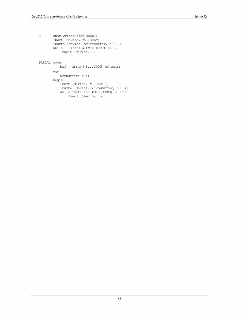
GPIB Library Software User's Manual IBWRTA
C char writebuffer[5000]; ibwrt (device, "UPLOAD") ibwrta (device, writebuffer, 5000); while ( (ibsta & CMPL+EERR) == 0) ibwait (device, 0)
PASCAL type buf = array [1...5000] of char;
var wrtbuffer: buf; begin ibwrt (device, 'UPLOAD'); ibwrta (device, writebuffer, 5000); while ibsta and (CMPL+EERR) = 0 do ibwait (device, 0);
83
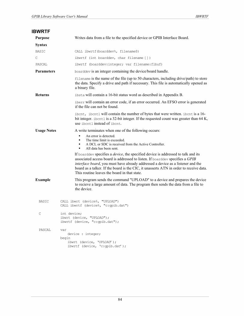
GPIB Library Software User's Manual IBWRTF
IBWRTF Purpose Writes data from a file to the specified device or GPIB Interface Board.
Syntax BASIC CALL ibwrtf(boarddev%, filename$) C ibwrtf (int boarddev, char filename [])
PASCAL ibwrtf (boarddev:integer; var filename:flbuf)
Parameters boarddev is an integer containing the device/board handle.
filename is the name of the file (up to 50 characters, including drive/path) to store the data. Specify a drive and path if necessary. This file is automatically opened as a binary file.
Returns ibsta will contain a 16-bit status word as described in Appendix B.
iberr will contain an error code, if an error occurred. An EFSO error is generated if the file can not be found.
ibcnt, ibcntl will contain the number of bytes that were written. ibcnt is a 16-bit integer. ibcntl is a 32-bit integer. If the requested count was greater than 64 K, use ibcntl instead of ibcnt.
Usage Notes A write terminates when one of the following occurs: An error is detected. The time limit is exceeded. A DCL or SDC is received from the Active Controller. All data has been sent.
If boarddev specifies a device, the specified device is addressed to talk and its associated access board is addressed to listen. If boarddev specifies a GPIB interface board, you must have already addressed a device as a listener and the board as a talker. If the board is the CIC, it unasserts ATN in order to receive data. This routine leaves the board in that state.
Example This program sends the command "UPLOAD" to a device and prepares the device to recieve a large amount of data. The program then sends the data from a file to the device.
BASIC CALL ibwrt (device%, "UPLOAD")
CALL ibwrtf (device%, "c:gpib.dat") C int device;
ibwrt (device, "UPLOAD"); ibwrtf (device, "c:gpib.dat");
PASCAL var
device : integer; begin ibwrt (device, ‘UPLOAD’); ibwrtf (device, ‘c:gpib.dat’);
84

GPIB Library Software User's Manual IBWRTI (QuickBASIC, BASIC only)
IBWRTI (QuickBASIC, BASIC only) Purpose Writes data from an integer array.
Syntax BASIC CALL ibwrti(boarddev%, iarr%(), bytecount&) C Not Supported
PASCAL Not Supported
Parameters boarddev is an integer containing the device/board handle.
iarr is the integer array that is written to the device.
bytecount specifies the number of bytes to be written.
Returns ibsta will contain a 16-bit status word as described in Appendix B.
ibcnt, ibcntl will contain the number of bytes that were written. ibcnt is a 16-bit integer. ibcntl is a 32-bit integer. If the requested count was greater than 64 K, use ibcntl instead of ibcnt.
iberr will contain an error code of the first error detected, if an error occurred. An EADR results if the boarddev specifies a board and the board has not already been addressed to talk.
Usage Notes As data is written, each byte pair is treated as an integer.
C and PASCAL users should use ibwrt for both strings and integers.
Example This example writes 90 bytes of data from a device address at MTA 15 (hex 4F, ASCII 0) to GPIB Board 1. The GPIB board's listen address is MLA 1. (hex 21, ASCII !).
BASIC DIM iarr%(90)
CALL ibfind ("GPIB1", brd1%) CALL ibcmd (brd1%, "?0!") CALL ibwrti (brd1%, iarr%(), 90)
C Not Supported
PASCAL Not Supported
85

GPIB Library Software User's Manual IBWRTIA (QuickBASIC, BASIC only)
IBWRTIA (QuickBASIC, BASIC only) Purpose Writes data asynchronously data from an integer array.
Syntax BASIC CALL ibwrtia(boarddev%, iarr%(), bytecount&) C Not Supported
PASCAL Not Supported
Parameters boarddev is an integer containing the device/board handle.
iarr is the integer array which is written to the device. The array can be of type single, double, or long. iarr can not be a dynamic array.
bytecount specifies the maximum number of bytes to be written.
Returns ibsta will contain a 16-bit status word as described in Appendix B.
ibcnt, ibcntl will contain the number of bytes that were written. ibcnt is a 16-bit integer. ibcntl is a 32-bit integer. If the requested count was greater than 64 K, use ibcntl instead of ibcnt.
iberr will contain an error code of the first error detected, if an error occurred. An EADR results if boarddev specifies a board and the board has not already been addressed to talk.
Usage Notes As data is written, each byte pair is treated as an integer.
Once an asynchronous I/O call has begun, any further calls to a GPIB library routine, except for ibwrt and those functions which do not specify a device or GPIB Interface Board, cannot be executed until the I/O has finished and the GPIB driver and the application have been re-synchronized. This is accomplished by calling one of the following:
ibwait The driver and applications are synchronized (mask contains CMPL).
ibstop The asynchronous I/O is canceled, and the driver and application are synchronized.
ibonl The asynchronous I/O is canceled, the interface has been reset and the driver and application are synchronized.
Re-synchronization is successful if a CMPL is returned to ibsta. See Appendix C.
C and Pascal users should use ibwrta.
Example This example writes 90 bytes of data from a device address at MTA 15 (hex 4F, ASCII 0) to GPIB Board 1. The GPIB board's listen address is MLA 1. (hex 21, ASCII !).
BASIC DIM iarr%(90)
CALL ibfind("GPIB1", brd1%) CALL ibcmd (brd1%, "?0!") CALL ibwrtia (brd1%, iarr%(), 90)
C Not Supported
PASCAL Not Supported
86

5GPIB-488.2 Library Reference This chapter describes each of the GPIB-488.2 routines. Each description provides a brief definition of the routine, its syntax, parameters, and any values which are returned. Any special usage notes and an example of are also given. The routines are listed in alphabetical order. lists the GPIB-488.2 routines. Table 5-1
Table 5-1. GPIB-488.2 routines Name Description AllSpoll Serial polls all devices DevClear Clears a single device DevClearList Clears multiple devices EnableLocal Enables local programming of a device EnableRemote Enables remote programming of a device FindLstn Find all Listeners FindRQS Find device requesting service PassControl Make another device the Active Controller PPoll Conduct a parallel poll PPollConfig Configure a device for parallel polls PPollUnconfig Unconfigure devices for parallel polls RcvRespMsg Read data from a previuosly addressed GPIB device ReadStatusByte Serial poll a single device Receive Read data from a GPIB device ReceiveSetup Address device as talker and GPIB Interface Board as Listener ResetSys Initialize a GPIB system Send Send data to one device SendCmds Send GPIB commands SendDataBytes Send data to previously addressed GPIB devices SendIFC Assert the IFC line SendList Send data to multiple GPIB devices SendLLO Send Local Lockout (LLO) to all devices SendSetup Prepare devices to receive data SetRWLS Put devices in Remote with Lockout state TestSRQ Determine status of SRQ line TestSys Force devices to conduct self-tests Trigger Trigger a single device TriggerList Trigger multiple devices WaitSRQ Wait until a device asserts SRQ
Note 488.2 addresses contain two bytes packed into a word – the low byte is the primary address and the high byte is the secondary address. If secondary addressing is not used, the high byte should be zero.
Table 5-2. 488.2 Address word HIGH BYTE LOW BYTE Secondary Address (0 or 96-126) Primary Address (0-30)
488.2 routines use a board index as the first argument (typically zero) – not a handle.
87

GPIB Library Software User's Manual AllSpoll
AllSpoll Purpose Performs a serial poll on specified devices.
Syntax BASIC Call AllSpoll (board%, addresslist%(), resultlist%())
C AllSpoll (int board, short addresslist[], short resultlist[])
Parameters board is an integer which identifies the GPIB board to be used for this operation. In most applications, this value is 0.
addresslist is an array of GPIB addresses, terminated by the value NOADDR. These addresses identify the devices to be serial polled.
Returns resultlist is an arraywhich contains the results of the serial poll. Once a device has been serial polled, the results of the serial poll are stored in the corresponding element of resultlist.
ibsta will contain a 16-bit status word as described in Appendix B.
iberr will contain an error code, if an error occurred. If a device times out, iberr contains Error 6 – EABO (see Appendix C), and ibcnt contains the isndex of the timed-out device.
Usage Notes To poll only one GPIB device, use ReadStatusByte.
Example This example serial polls two devices (GPIB address 6 and 7) connected to GPIB board 0.
BASIC DIM addresslist%(3)
DIM resultlist%(2) addresslist% (0) = 6 addresslist% (1) = 7 addresslist% (2) = NOADDR CALL AllSpoll(0,addresslist%(),resultlist%())
C short addresslist[3] = {6,7,NOADDR}; short resultlist[2]; AllSpoll (0, addresslist, resultlist);
88

GPIB Library Software User's Manual DevClear
DevClear Purpose Clears one device.
Syntax BASIC CALL DevClear(board%, address%)
C DevClear(int board, short address)
Parameters board is an integer which identifies the GPIB board to be used for this operation. In most applications, this value is 0.
address is the GPIB address of the device to clear.
Returns ibsta will contain a 16-bit status word as described in Appendix B.
iberr will contain an error code, if an error occurred.
Usage Notes This routine sends the GPIB Selected Device Clear (SDC) message to the specified device.
To clear multiple devices, use the DevClearList routine.
If address is set to NOADDR, then all connected devices on the GPIB is cleared via the Universal Device Clear (UDC) message.
Example This example clears the device at GPIB primary address 4, secondary address 30 connected to GPIB board 0.
BASIC address% = 4 + 256*30
`CALL DevClear (0, address%)
C DevClear(0, MakeAddr (4,30)); /* Use MakeAddr macro (in WINDECL.H) to pack primary and secondary address */
89

GPIB Library Software User's Manual DevClearList
DevClearList Purpose Clears specified devices.
Syntax BASIC CALL DevClearList(board%, addresslist%())
C DevClearList(int board, short addresslist[])
Parameters board is an integer which identifies the GPIB board to be used for this operation. In most applications, this value is 0.
addresslist is an array of GPIB addresses, terminated by the value NOADDR. These addresses identify the devices to be cleared.
Returns ibsta will contain a 16-bit status word as described in Appendix B.
iberr will contain an error code, if an error occurred.
Usage Notes This routine sends the GPIB Selected Device Clear (SDC) to the devices specified by addresslist.
To clear all devices in BASIC/QuickBASIC, use an array containing only the NOADDR value. To clear all devices in C, pass a NULL value. This sends the GPIB the Universal Device Clear (DCL) message.
To clear only one device, use DevClear.
Example This clears the devices at GPIB addresses 6 and 7, connected to GPIB board 0.
BASIC DIM addresslist%(3)
addresslist% (0) = 6 addresslist% (1) = 7 addresslist% (2) = NOADDR CALL DevClearList(0, addresslist% ())
C short addresslist[3] = {6,7,NOADDR}; DevClearList(0, addresslist);
90
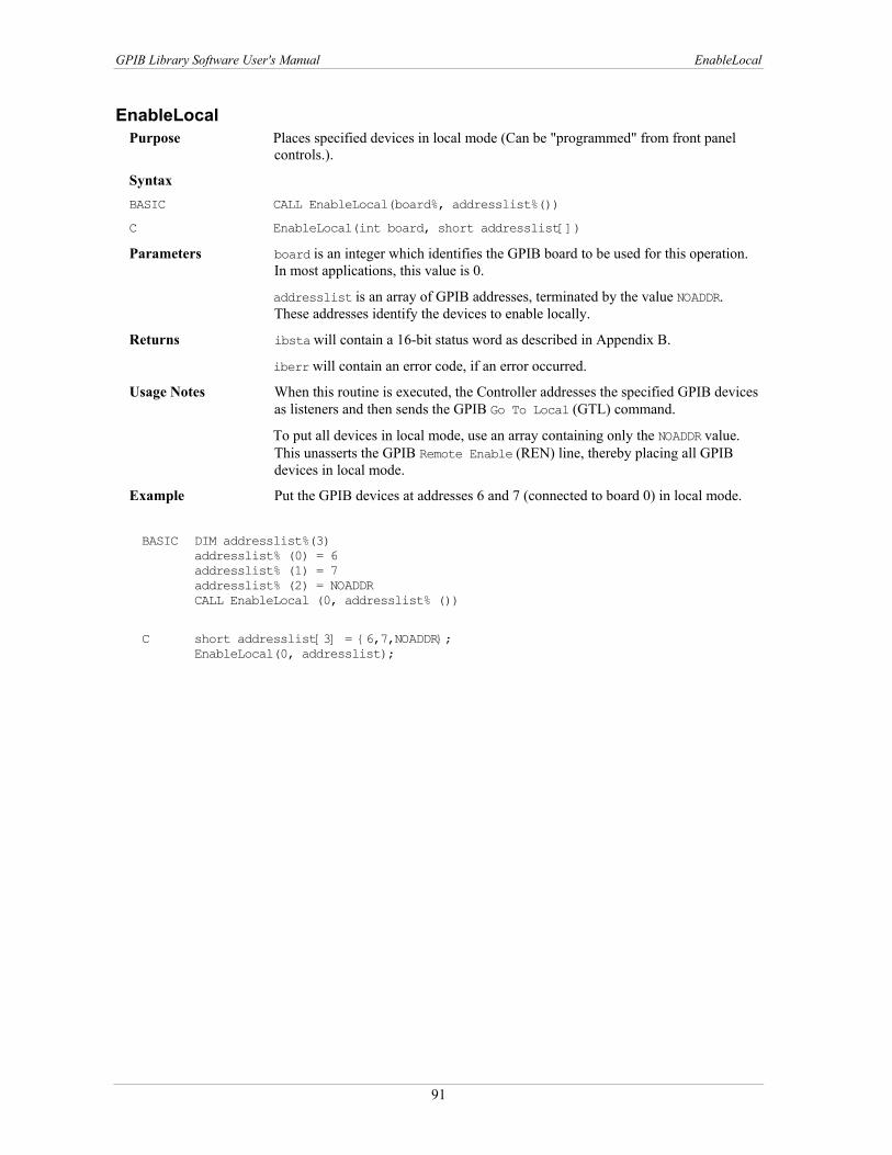
GPIB Library Software User's Manual EnableLocal
EnableLocal Purpose Places specified devices in local mode (Can be "programmed" from front panel
controls.).
Syntax BASIC CALL EnableLocal(board%, addresslist%())
C EnableLocal(int board, short addresslist[])
Parameters board is an integer which identifies the GPIB board to be used for this operation. In most applications, this value is 0.
addresslist is an array of GPIB addresses, terminated by the value NOADDR. These addresses identify the devices to enable locally.
Returns ibsta will contain a 16-bit status word as described in Appendix B.
iberr will contain an error code, if an error occurred.
Usage Notes When this routine is executed, the Controller addresses the specified GPIB devices as listeners and then sends the GPIB Go To Local (GTL) command.
To put all devices in local mode, use an array containing only the NOADDR value. This unasserts the GPIB Remote Enable (REN) line, thereby placing all GPIB devices in local mode.
Example Put the GPIB devices at addresses 6 and 7 (connected to board 0) in local mode.
BASIC DIM addresslist%(3)
addresslist% (0) = 6 addresslist% (1) = 7 addresslist% (2) = NOADDR CALL EnableLocal (0, addresslist% ())
C short addresslist[3] = {6,7,NOADDR}; EnableLocal(0, addresslist);
91
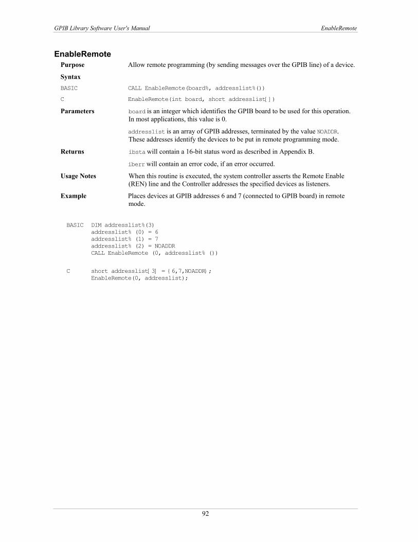
GPIB Library Software User's Manual EnableRemote
EnableRemote Purpose Allow remote programming (by sending messages over the GPIB line) of a device.
Syntax BASIC CALL EnableRemote(board%, addresslist%())
C EnableRemote(int board, short addresslist[])
Parameters board is an integer which identifies the GPIB board to be used for this operation. In most applications, this value is 0.
addresslist is an array of GPIB addresses, terminated by the value NOADDR. These addresses identify the devices to be put in remote programming mode.
Returns ibsta will contain a 16-bit status word as described in Appendix B.
iberr will contain an error code, if an error occurred.
Usage Notes When this routine is executed, the system controller asserts the Remote Enable (REN) line and the Controller addresses the specified devices as listeners.
Example Places devices at GPIB addresses 6 and 7 (connected to GPIB board) in remote mode.
BASIC DIM addresslist%(3)
addresslist% (0) = 6 addresslist% (1) = 7 addresslist% (2) = NOADDR CALL EnableRemote (0, addresslist% ())
C short addresslist[3] = {6,7,NOADDR}; EnableRemote(0, addresslist);
92

GPIB Library Software User's Manual FindLstn
FindLstn Purpose Finds all listeners on the GPIB.
Syntax BASIC CALL FindLstn(board%,addresslist%(),resultlist%(), limit%)
C FindLstn(int board, short addresslist[], short resultlist[], int limit)
Parameters board is an integer which identifies the GPIB board to be used for this operation. In most applications, this value is 0.
addresslist is an array of GPIB addresses, terminated by the value NOADDR.
limit is an integer which specifies how many address entries can be placed into the resultlist array. Set to the size of the resultlist array.
Returns resultlist will contain the addresses of all detected listeners. This array must be large enough to hold all possible addresses.
ibsta will contain a 16-bit status word as described in Appendix B.
iberr will contain an error code, if an error occurred. An ETAB (20) error indicates that more listeners are present on the GPIB bus than limit will allow to be placed in resultlist. In this case, ibcnt contains the number of addresses actually placed in resultlist.
Usage Notes The addresses specified by addresslist are tested to see if a listening device is present. If a listener is found at a primary address, its address is placed in resultlist. If no listeners are detected at a primary address, then all secondary addresses associated with that primary address are tested. If any listeners are detected, their addresses are placed in resultlist. You can use this routine to determine how many devices on the network are capable of listening. Once these devices are detected, they can be identified by their response to identification request messages.
Example This example verifies if listening devices are present at GPIB primary addresses 6 and 7 on Board 0.
BASIC DIM addresslist%(3)
DIM resultlist%(4)addresslist% (0) = 6
addresslist% (1) = 7
addresslist% (2) = NOADDR limit% = 4 CALL FindLstn(0,addresslist%(),resultlist%(), limit%)
C short addresslist[3] = {6,7,NOADDR}; short resultlist[4]; FindLstn(0, addresslist, resultlist, 4);
93

GPIB Library Software User's Manual FindRQS
FindRQS Purpose Identify the device requesting service.
Syntax BASIC CALL FindRQS(board%, addresslist%(), result%)
C FindRQS(int board, short addresslist[], short *result)
Parameters board is an integer which identifies the GPIB board to be used for this operation. In most applications, this value is 0.
addresslist is an array of GPIB addresses, terminated by the value NOADDR. The devices located at these addresses are serial polled until the one asserting SRQ is located.
Returns result will contain the returned status byte of the device asserting SRQ.
ibcnt will contain the index ( in addresslist) identifying the device's address.
ibsta will contain a 16-bit status word as described in Appendix B.
iberr will contain an error code, if an error occurred. iberr contains the error code ETAB, if no device is requesting service. In this case, ibcnt contains NOADDR's index.
iberr will contain the error code EABO, if a device times out while responding to its serial poll. In this case, ibcnt contains the index of the timed-out device.
Usage Notes None.
Example Identifies which of the devices at GPIB addresses 6 and 7 (connected to board 0) is requesting service.
BASIC DIM addresslist%(3)
addresslist% (0) = 6 addresslist% (1) = 7 addresslist% (2) = NOADDR CALL FindRQS(0, addresslist% (), result%)
C short addresslist[3] = {6,7,NOADDR}; short result; FindRQS (0, addresslist, &result);
94

GPIB Library Software User's Manual PassControl
PassControl Purpose Makes another device the Active Controller.
Syntax BASIC CALL PassControl(board%, address%)
C PassControl(int board, short address)
Parameters board is an integer which identifies the GPIB board to be used for this operation. In most applications, this value is 0.
address is an integer representing the GPIB address of the device that is to become the controller. The low byte of the integer contains the device's primary GPIB address. The high byte of the address contains the device's secondary GPIB address. If the device has no secondary address, the high byte of address is 0.
Returns ibsta will contain a 16-bit status word as described in Appendix B.
iberr will contain an error code, if an error occurred.
Usage Notes When this routine is executed, the GPIB Take Control (TCT) command is issued. This forces the Active Controller to pass control to the device at the specified address. This device must have Controller capability.
Example This example would make the device connected to Board 0 and whose GPIB address is 6 the Active Controller.
BASIC address% = 6
CALL PassControl(0, address%)
C PassControl(0, 6);
95

GPIB Library Software User's Manual Ppoll
Ppoll Purpose Performs a parallel poll.
Syntax BASIC CALL PPoll(board%, result)
C PPoll(int board, short *result)
Parameters board is an integer which identifies the GPIB board to be used for this operation. In most applications, this value is 0.
Returns result will contain the eight-bit result of the parallel poll. Each bit of the poll result contains one bit of status information from each device which has been configured for parallel polls. The value of each bit is dependent on the latest parallel poll configuration sent to the devices via PPollConfig and the individual status of the devices.
ibsta will contain a 16-bit status word as described in Appendix B.
iberr will contain an error code, if an error occurred.
Usage notes None.
Example Parallel polls devices connected to board 0.
BASIC CALL PPoll(0, result%)
C short result;
PPoll(0, &result);
96

GPIB Library Software User's Manual PPollConfig
PPollConfig Purpose Configures a device for parallel polls.
Syntax BASIC CALL PPollConfig(board%, address%, dataline%, sense%)
C PPollConfig(int board, short address, int dataline, int sense)
Parameters board is an integer which identifies the GPIB board to be used for this operation. In most applications, this value is 0.
address is the address of the GPIB device to be configured for a parallel poll.
dataline specifies which data line (1-8) the device uses to respond to a parallel poll.
sense can be 1 or 0, specifying the condition under which the data line is to be asserted/unasserted. The device compares this value to its Individual Status Bit (IST) and then responds accordingly. For example, if sense = 0 and the device asserts the specified data line if its IST bit = 0 and unassert the data line if its IST bit = 1.
Returns ibsta will contain a 16-bit status word as described in Appendix B.
iberr will contain an error code, if an error occurred.
Usage notes Remember that if a device is locally configured for a parallel poll, the Controller's parallel poll configuration instruction is ignored.
Example Configures the device connected to board 0 at address 6 to respond to parallel polls on line 7 with sense 1. The device asserts line 7 if its IST bit = 1, and unasserts line 7 if IST = 0.
BASIC Call PpollConfig(0, 6, 7, 1)
C PPollConfig(0, 6, 7, 1)
97

GPIB Library Software User's Manual PPollUnconfig
PPollUnconfig Purpose Unconfigures devices for parallel polls.
Syntax BASIC CALL PPollUnconfig(board%, addresslist%())
C PPollUnconfig(int board, short addresslist[])
Parameters board is an integer which identifies the GPIB board to be used for this operation. In most applications, this value is 0.
addresslist is an array of GPIB addresses, terminated by the value NOADDR. These addresses identify the devices that do not respond to a parallel poll.
Returns ibsta will contain a 16-bit status word as described in Appendix B.
iberr will contain an error code, if an error occurred.
Usage Notes To unconfigure all devices, in BASIC use an array containing only the NOADDR value. This sends the GPIB Parallel Poll Unconfigure (PPU) command.
Example Unconfigure the devices connected to board 0 and located at GPIB addresses 6 and 7.
BASIC DIM addresslist%(3)
addresslist% (0) = 6 addresslist% (1) = 7 addresslist% (2) = NOADDR CALL PPollUnconfig(0, addresslist% ())
C short addresslist[3] = {6, 7, NOADDR}; PPollUnconfig(0, addresslist);
98

GPIB Library Software User's Manual RcvRespMsg
RcvRespMsg Purpose Reads data from a previously addressed device.
Syntax BASIC CALL RcvRespMsg(board%, data$, termination%)
C RcvRespMsg(int board, char data[], long count, int termination)
Parameters board is an integer which identifies the GPIB board to be used for this operation. In most applications, this value is 0.
count specifies the maximum number of data bytes which are to be read. This parameter is not required in BASIC, since count is set to the length of the data string.
termination is the flag used to signal the end of data. If termination equals a value between 0 and 00FF hex, the corresponding ASCII character is the termination character. The read is stopped when this character is detected. If termination = STOPend (A constant defined in the header file.), then the read is stopped when EOI is detected.
Returns data is the string that receives the data. In BASIC, it is important that you allocate a large enough string to accomodate all of the data.
ibsta will contain a 16-bit status word as described in Appendix B.
iberr will contain an error code, if an error occurred.
Usage Notes You must address the appropriate devices as Listeners/Talkers prior to calling this routine. The input data string is not terminated with a zero byte.
Example A previously addressed Listener receives 50 bytes of data from a previously addressed Talker. The transmission is terminated when EOI is detected.
BASIC DIM data AS STRING*50
CALL RcvMsgResp(0, data, STOPend)
C char data[50]; RcvRespMsg(0, data, 50, STOPend)
99
GPIB Library Software User's Manual ReadStatusByte
ReadStatusByte Purpose Serial poll a single device and read its status byte.
Syntax BASIC CALL ReadStatusByte(board%, address%, result%)
C ReadStatusByte(int board, int address, short *result)
Parameters board is an integer which identifies the GPIB board to be used for this operation. In most applications, this value is 0.
address is an integer representing the GPIB address of the device that is to be serial polled.
Returns result will contain the status byte. The high byte of result is always 0.
ibsta will contain a 16-bit status word as described in Appendix B.
iberr will contain an error code, if an error occurred.
Usage Notes None.
Example This example serial polls the device at address 2 and retrieves its status byte.
BASIC CALL ReadStatusByte (0, 2, result%)
C short result;
ReadStatusByte (0, 2, &result);
100

GPIB Library Software User's Manual Receive
Receive Purpose Reads data from a GPIB device.
Syntax BASIC CALL Receive(board%, address%, data$, termination%)
C Receive(int board, int address,char data[], unsigned long count, int termination)
Parameters board is an integer which identifies the GPIB board to be used for this operation. In most applications, this value is 0.
address is an integer representing the GPIB address of the device that is to be read from.
count specifies the maximum number of data bytes which are to be read. This parameter is not required in BASIC, since count is set to the string length of the data.
termination is the flag used to signal the end of data. If termination equals a value between 0 and 00FF hex, the corresponding ASCII character is the termination character. The read is stopped when this character is detected. If termination = STOPend (constant defined in the header file), then the read is stopped when EOI is detected.
Returns data is the string that receives the data. In BASIC, it is important that you allocate a large enough string to accomodate all of the data.
ibsta will contain a 16-bit status word as described in Appendix B.
iberr will contain an error code, if an error occurred.
Usage Notes The input data string is not terminated with a zero byte.
Example Receive 50 bytes of data from the specified talker (device at address 2, connected to board). EOI signals the end of the message.
BASIC data$ = space$(50) CALL Receive (0, 2, data$, STOPend)
C char data[50]; Receive (0, 2, data, 50, STOPend);
101

GPIB Library Software User's Manual ReceiveSetup
ReceiveSetup Purpose Address a GPIB Interface Board as a Listener and a GPIB device as a Talker, in
preparation for data transmission.
Syntax BASIC CALL ReceiveSetup(board%, address%)
C ReceiveSetup(int board, short address)
Parameters board An integer which identifies the GPIB board to be used for this operation. In most applications, this value is 0.
address is an integer representing the GPIB address of the device to send the data.
Returns ibsta will contain a 16-bit status word as described in Appendix B.
iberr will contain an error code, if an error occurred.
Usage Notes In order to actually transfer any data, you must call a routine such as RcvRespMsg following this routine.
This routine is useful in instances where you need to transfer multiple blocks of data between devices. For example, you could initially address the devices using ReceiveSetup, then make multiple calls of RcvRespMsg to transfer the data.
For typical cases, Receive is simpler to use, since it takes care of both the setup and the data transfer.
Example This example instructs a GPIB device at address 5 to send data to GPIB Board 0. Up to 50 bytes of data is received and then stored in a string. The message is terminated with an EOI.
BASIC DIM message AS STRING*50
CALL ReceiveSetup(0, 5) CALL RcvRespMsg(0, message, STOPend)
C char message[100]; ReceiveSetup(0, 5); RcvRespMsg (0, message, 50, STOPend);
102

GPIB Library Software User's Manual ResetSys
ResetSys Purpose Initializes GPIB System.
Syntax BASIC CALL ResetSys(board%, addresslist%())
C ResetSys(int board, short addresslist[])
Parameters board is an integer which identifies the GPIB board to be used for this operation. In most applications, this value is 0.
addresslist is an array of GPIB addresses, terminated by the value NOADDR. These addresses identify the devices on the system to be reset.
Returns ibsta will contain a 16-bit status word as described in Appendix B.
iberr will contain an error code, if an error occurred.
Usage Notes This routine initializes the GPIB bus and all specified devices. First, the system controller asserts the REN (Remote Enable) line and then the IFC (Interface Clear) line. This action unlistens and untalks all of the attached GPIB devices and causes the system controller to become the Controller-In-Charge (CIC).
The Device Clear (DCL) message is then sent to all of the connected devices. This forces the devices to return to their default states and ensures that they can receive the Reset (RST) message. A reset message (RST) is then sent to all of the devices specified by addresslist. This resets the devices to specific parameters.
Example This example resets the GPIB devices connected to GPIB board 0 and assigned GPIB bus addresses of 6 and 7.
BASIC DIM addresslist%(3)
addresslist% (0) = 6 addresslist% (1) = 7 addresslist% (2) = NOADDR CALL ResetSys (0, addresslist%())
C short addresslist[3] = {6, 7, NOADDR}; ResetSys(0, addresslist);
103

GPIB Library Software User's Manual Send
Send Purpose Sends data to one GPIB device.
Syntax BASIC CALL Send(board%, address%, data$, eotmode%)
C Send (int board, short address,char data[], long count, int eotmode)
Parameters board is an integer which identifies the GPIB board to be used for this operation. In most applications, this value is 0.
address is an integer representing the GPIB address of the device to receive the data.
data is the string of data which is sent to the device.
count specifies the maximum number of data bytes which are to be sent to the device. This parameter is not required in BASIC, since count is set to the string length of the data.
eotmode is the flag used to signal the end of data.
Returns ibsta will contain a 16-bit status word as described in Appendix B.
iberr will contain an error code, if an error occurred.
Usage Notes When this routine is executed, the specified GPIB board is addressed as a Talker, the designated GPIB device is addressed as a Listener and the number of bytes (specified by count) in data is sent. Values for eotmode are:
NLend - Send NL (Line Feed) with EOI after last data byte. DABend - Send EOI with the last data byte in the string. NULLend - Do not mark the end of the transfer.
These constants are defined in the header file.
Example In this example, GPIB board 0 sends an identification query to the GPIB device at address 3. End of data is signalled by an EOI.
BASIC Call Send (0, 3, "*IDN?", DABend)
C Send (0, 3, "*IDN?", DABend)
104

GPIB Library Software User's Manual SendCmds
SendCmds Purpose Send GPIB commands.
Syntax BASIC CALL SendCmds (board%, commands$)
C SendCmds (int board, char commands[], unsigned long count)
Parameters board is an integer which identifies the GPIB board to be used for this operation. In most applications, this value is 0.
commands is a string containing the GPIB command bytes to be sent.
count specifies the maximum number of command bytes which are to be sent. This parameter is not required in BASIC, since count is set to the string length of the data.
Returns ibsta will contain a 16-bit status word as described in Appendix B.
iberr will contain an error code, if an error occurred.
Usage Notes This routine is useful in situations where specialized GPIB command sequences are called for.
Example The GPIB board (at 0) simultaneously triggers the GPIB devices at addresses 8 and 9 and quickly puts them in local mode.
BASIC CALL SendCmds(0, chr$(&3F)+chr$(&40)+chr$(&H2 8)
C SendCmds0, "\x3F\x40\x28\x29\x04\x01",6);
105

GPIB Library Software User's Manual SendDataBytes
SendDataBytes Purpose Sends data to previously addressed devices.
Syntax BASIC CALL SendDataBytes (board%, data$, eotmode%)
C SendDataBytes(int board, char data[], long count, int eotmode)
Parameters board An integer which identifies the GPIB board to be used for this operation. In most applications, this value is 0.
data is the string that contains the data which is sent to the device.
count specifies the maximum number of data bytes which are to be sent to the device. This parameter is not required in BASIC, since count is set to the string length of the data.
Eotmode is the flag used to signal the end of data.
Returns ibsta will contain a 16-bit status word as described in Appendix B.
iberr will contain an error code, if an error occurred.
Usage Notes This routine assumes that the desired GPIB listeners have already been addressed (by using SendSetup, for example).
Values for eotmode are as follows: NLend - Send NL (Line Feed) with EOI after last data byte. DABend - Send EOI with the last data byte in the string. NULLend - Do not mark the end of the transfer.
These constants are defined in the header files.
Example In this example, GPIB board 0 sends an identification query to all previously addressed listeners. End of data is signaled by an EOI.
BASIC Call SendDataBytes (0,"*IDN?", DABend)
C SendDataBytes (0, "*IDN?", 5, DABend)
106
GPIB Library Software User's Manual SendIFC
SendIFC Purpose Clears the GPIB bus by asserting the IFC (Interface Clear) line.
Syntax BASIC CALL SendIFC(board%)
C SendIFC(int board)
Parameters board is an integer which identifies the GPIB board to be used for this operation. In most applications, this value is 0.
Returns ibsta will contain a 16-bit status word as described in Appendix B.
iberr will contain an error code, if an error occurred.
Usage Notes This routine is used as part of the GPIB initialization procedure. When the system controller asserts the IFC line, it unlistens and untalks all GPIB devices, forcing them to an idle state. The system controller also becomes the Controller-In-Charge (CIC).
Example Clears the GPIB bus from Board 0.
BASIC CALL SendIFC(0)
C SendIFC(0);
107
GPIB Library Software User's Manual SendList
SendList Purpose Sends data to multiple GPIB devices.
Syntax BASIC CALL SendList(board%, addresslist(), data$, eotmode%)
C SendList(int board, short addresslist[], char data[], long count, int eotmode)
Parameters board is an integer which identifies the GPIB board to use for this operation. In most applications, this value is 0.
addresslist is an array of GPIB addresses, terminated by the value NOADDR. These addresses identify the devices on the system to reset.
data is the string containing the data to send.
count specifies the maximum number of data bytes to send to the device. This parameter is not required in BASIC, since count is set to the string length of the data.
eotmode is the flag used to signal the end of data.
Returns ibsta will contain a 16-bit status word as described in Appendix B.
iberr will contain an error code, if an error occurred.
Usage Notes When this routine is executed, the specified GPIB board is addressed as a Talker and the designated GPIB devices as Listeners. The board then sends the given number of bytes of data from the data string to the listening GPIB devices.
Values for eotmode are as follows: NLend - Send NL (Line Feed) with EOI after last data byte. DABend - Send EOI with the last data byte in the string. NULLend - Do not mark the end of the transfer.
These constants are defined in the header files.
Example In this example, GPIB board 0 sends an identification query to the GPIB devices at addresses 6 and 7. End of data is signalled by an EOI.
BASIC DIM addresslist%(3)
addresslist% (0) = 6
addresslist% (1) = 7
addresslist% (2) = NOADDR
Call SendList0, addresslist%(), "*IDN?", DABend)
C short addresslist%[3] = {6, 7, NOADDR};
SendList (0, addresslist, "*IDN?", 5, DABend)
108

GPIB Library Software User's Manual SendLLO
SendLLO Purpose Sends Local Lockout (LLO) message to all GPIB devices.
Syntax BASIC CALL SendLLO(board%)
C SendLLO(int board)
Parameters board is an integer which identifies the GPIB board to be used for this operation. In most applications, this value is 0.
Returns ibsta will contain a 16-bit status word as described in Appendix B.
iberr will contain an error code, if an error occurred.
Usage Notes When this routine is executed, the specified GPIB board sends the GPIB Local Lockout (LLO) message to all devices. This means that once they have been addressed as listeners, the devices respond only to messages sent over the GPIB by the Controller. (In other words, they can not be locally programmed from front panel controls.) Only the Controller can return them to a local programming state.
Example In this example, GPIB board 0 sends a Local Lockout to its connected GPIB devices.
BASIC CALL SendLLO (0)
C SendLLO (0);
109

GPIB Library Software User's Manual SendSetup
SendSetup Purpose Addresses a GPIB board as a Talker and the specified GPIB devices as Listeners.
Syntax BASIC CALL SendSetup (board%, addresslist% ())
C SendSetup(int board, short addresslist [])
Parameters board is an integer which identifies the GPIB board to be used for this operation. In most applications, this value is 0.
addresslist is an array of GPIB addresses, terminated by the value NOADDR. These addresses identify the devices to address as Listeners.
Returns ibsta will contain a 16-bit status word as described in Appendix B.
iberr will contain an error code, if an error occurred.
Usage Notes Following this routine, you should call a routine such as SendDataBytes to actually transfer the data.
Example This example prepares GPIB board 0 to send data to GPIB devices 6 and 7.
BASIC DIM addresslist%(3)
addresslist%(0) = 6
addresslist%(1) = 7
addresslist%(2) = NOADDR
CALL SendSetup(0, addresslist())
C short addresslist[3] = {6, 7, NOADDR};
SendSetup(0, addresslist);
110

GPIB Library Software User's Manual SetRWLS
SetRWLS Purpose Puts all devices in Remote state with Local Lockout and addresses specified
devices as Listeners.
Syntax BASIC CALL SetRWLS (board%, addresslist% ())
C SetRWLS(int board, short addresslist [])
Parameters board is an integer which identifies the GPIB board to be used for this operation. In most applications, this value is 0.
addresslist is an array of GPIB addresses, terminated by the value NOADDR. These addresses identify the devices to be put in remote mode.
Returns ibsta will contain a 16-bit status word as described in Appendix B.
iberr will contain an error code, if an error occurred.
Usage Notes This routine puts the specified devices in remote mode with local lockout. The system controller asserts the REN (Remote Enable) line and addresses the specified devices as listeners. These devices can then be programmed by messages sent over the GPIB bus. (In other words, they can not be locally programmed from front panel controls.)
Example This example puts all devices controlled by GPIB board 0 into Remote mode. Devices 6 and 7 are then addressed as Listeners by the Controller.
BASIC DIM addresslist%(3)
addresslist%(0) = 6 addresslist%(1) = 7 addresslist%(2) = NOADDR CALL SetRWLS(0, addresslist())
C short addresslist[3] = {6, 7, NOADDR}; SetRWLS(0, addresslist);
111

GPIB Library Software User's Manual TestSRQ
TestSRQ Purpose Evaluate state of SRQ line.
Syntax BASIC CALL TestSRQ (board%, result%)
C TestSRQ(int board, short *result)
Parameters board is an integer which identifies the GPIB board to be used for this operation. In most applications, this value is 0.
Returns result is equal to 1 if the GPIB SRQ line is asserted. result = 0 if the GPIB SRQ line is unasserted.
ibsta will contain a 16-bit status word as described in Appendix B.
iberr will contain an error code, if an error occurred.
Usage Notes TestSRQ will not alter the state of the SRQ line.
Example This example tests to see if SRQ is asserted.
BASIC CALL TestSRQ (0, result%)
IF result% = 1 then
'SRQ is asserted
ELSE
'No SRQ at this time
END IF
C Short result;
TestSRQ (0, &result);
if (result == 1)
{ /* SRQ is asserted */}
else
{ /* No SRQ at this time */}
112

GPIB Library Software User's Manual TestSys
TestSys Purpose Activate self-test procedures of specified devices.
Syntax BASIC CALL TestSys (board%, addresslist% (), resultlist%())
C SendSetup(int board, short addresslist [], short resultlist[])
Parameters board is an integer which identifies the GPIB board to use for this operation. In most applications, this value is 0.
addresslist is an array of GPIB addresses, terminated by the value NOADDR. These addresses identify the devices to perform self-tests.
Returns resultlist is an array which contaisn the results of each device's self-test procedure. According to the IEEE-488.2 standard, a result code of 0 indicates the device passed its test. Any other value indicates an error.
ibcnt will contain the number of devices which failed their tests.
ibsta will contain a 16-bit status word as described in Appendix B.
iberr will contain an error code, if an error occurred.
Usage Notes When this routine is executed, all of the devices identified within the addresslist array are concurrently sent a message which directs them to perform their self-test procedures. Each device returns an integer code indicating the results of its tests. This code is placed into the corresponding element of the resultlist array.
Example This example tells the devices at addresses 6 and 7 (from Board 0) to perform thier self-test procedures.
BASIC DIM resultlist%(2)
DIM addresslist%(3) addresslist%(0) = 6 addresslist%(1) = 7 addresslist%(2) = NOADDR CALL TestSys(0, addresslist(), resultlist())
C short addresslist[3] = {6, 7, NOADDR}; short resultlist[2]; TestSys(0, addresslist, resultlist);
113

GPIB Library Software User's Manual Trigger
Trigger Purpose Triggers one device.
Syntax BASIC CALL Trigger (board%, address%)
C Trigger(int board, short address)
Parameters board is an integer which identifies the GPIB board to used for this operation. In most applications, this value is 0.
address is an integer representing the GPIB address of the device to trigger. If address = NOADDR then all Listeners already addressed are triggered.
Returns ibsta will contain a 16-bit status word as described in Appendix B.
iberr will contain an error code, if an error occurred.
Usage Notes When this call is executed, the GPIB GET (Group Execute Trigger) message is sent to the specified device.
To trigger several GPIB devices, use TriggerList.
Example This example triggers a device connected to board 0 whose primary GPIB address is 6 and secondary address is 12.
BASIC CALL Trigger (0, 6 + 256*12)
C Trigger (0, MakeAddr (6, 12));
114
GPIB Library Software User's Manual TriggerList
TriggerList Purpose Triggers multiple GPIB devices
Syntax BASIC CALL TriggerList (board%, addresslist%())
C void TriggerList(int board, int addresslist[])
Parameters board is an integer which identifies the GPIB board to be used for this operation. In most applications, this value is 0.
addresslist is an array of GPIB addresses, terminated by the value NOADDR. These addresses identify the devices to be triggered. If this array contains only NOADDR (in C a NULL value is passed), all previously addressed listeners are triggered.
Returns ibsta will contain a 16-bit status word as described in Appendix B.
iberr will contain an error code, if an error occurred.
Usage Notes Use Trigger to trigger only one device.
Example This example triggers two devices simultanously. The devices are connected to board 0 and are at GPIB addresses 6 and 7.
BASIC DIM addresslist%(3)
addresslist%(0) = 6 addresslist%(1) = 7 addresslist%(2) = NOADDR CALL TriggerList(0, addresslist())
C short addresslist[3] = {6, 7, NOADDR}; TriggerList(0, addresslist);
115

GPIB Library Software User's Manual WaitSRQ
WaitSRQ Purpose Wait until a device asserts SRQ.
Syntax BASIC CALL WaitSRQ (board%, result%)
C WaitSRQ(int board, short *result)
Parameters board is an integer which identifies the GPIB board to use for this operation. In most applications, this value is 0.
Returns result indicates whether or not an SRQ occurred. If an SRQ occurs before the timeout expires, result = 1. Otherwise, result = 0.
ibsta will contain a 16-bit status word as described in Appendix B.
iberr will contain an error code, if an error occurred.
Usage Notes This call suspends operation until a device requests service or a timeout occurs. Follow this call with a FindRQS call to determine which device needs service.
Example Wait for a GPIB device to request service and then ascertain if device 6 or 7 requires service.
BASIC DIM addresslist%(3), resultlist(2)
addresslist%(0) = 6
addresslist%(1) = 7
addresslist%(2) = NOADDR
CALL WaitSRQ(0, result%)
IF result% = 1 then
CALL FindSRQ(0, addresslist%(),resultlist%())
END IF
C Short addresslist[3] = {6,7,NOADDR};
short resultlist[3];
short result;
WaitSRQ (0,&result);
if (result == 1)
{FindSRQ (0, addresslist, resultlist}
116
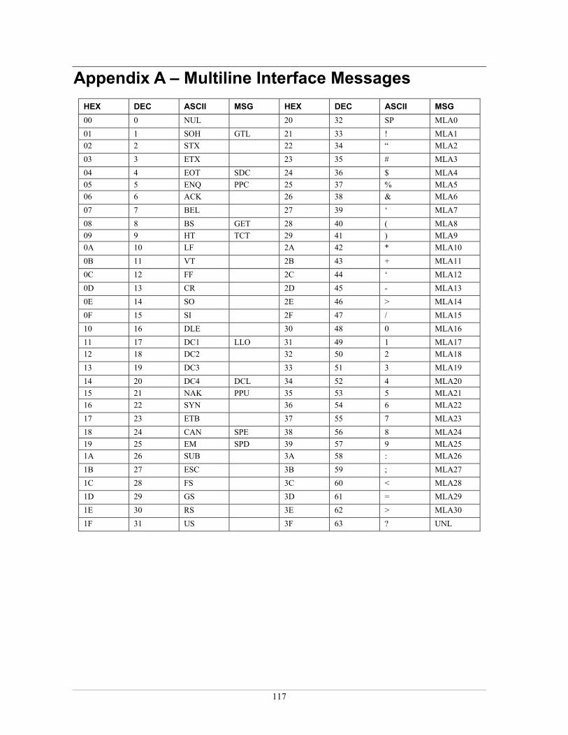
Appendix A – Multiline Interface Messages HEX DEC ASCII MSG HEX DEC ASCII MSG 00 0 NUL 20 32 SP MLA0 01 1 SOH GTL 21 33 ! MLA1 02 2 STX 22 34 “ MLA2 03 3 ETX 23 35 # MLA3 04 4 EOT SDC 24 36 $ MLA4 05 5 ENQ PPC 25 37 % MLA5 06 6 ACK 26 38 & MLA6 07 7 BEL 27 39 ‘ MLA7 08 8 BS GET 28 40 ( MLA8 09 9 HT TCT 29 41 ) MLA9 0A 10 LF 2A 42 * MLA10 0B 11 VT 2B 43 + MLA11 0C 12 FF 2C 44 ‘ MLA12 0D 13 CR 2D 45 - MLA13 0E 14 SO 2E 46 > MLA14 0F 15 SI 2F 47 / MLA15 10 16 DLE 30 48 0 MLA16 11 17 DC1 LLO 31 49 1 MLA17 12 18 DC2 32 50 2 MLA18 13 19 DC3 33 51 3 MLA19 14 20 DC4 DCL 34 52 4 MLA20 15 21 NAK PPU 35 53 5 MLA21 16 22 SYN 36 54 6 MLA22 17 23 ETB 37 55 7 MLA23 18 24 CAN SPE 38 56 8 MLA24 19 25 EM SPD 39 57 9 MLA25 1A 26 SUB 3A 58 : MLA26 1B 27 ESC 3B 59 ; MLA27 1C 28 FS 3C 60 < MLA28 1D 29 GS 3D 61 = MLA29 1E 30 RS 3E 62 > MLA30 1F 31 US 3F 63 ? UNL
117

GPIB Library Software User's Manual Appendix A – Multiline Interface Messages
HEX DEC ASCII MSG HEX DEC ASCII MSG 40 64 @ MTA0 60 96 ‘ MSA0,PPE 41 65 A MTA1 61 97 a MSA1,PPE 42 66 B MTA2 62 98 b MSA2,PPE 43 67 C MTA3 63 99 c MSA3,PPE 44 68 D MTA4 64 100 d MSA4,PPE 45 69 E MTA5 65 101 e MSA5,PPE 46 70 F MTA6 66 102 f MSA6,PPE 47 71 G MTA7 67 103 g MSA7,PPE 48 72 H MTA8 68 104 h MSA8,PPE 49 73 I MTA9 69 105 i MSA9,PPE 4A 74 J MTA10 6A 106 j MSA10,PPE 4B 75 K MTA11 6B 107 k MSA11,PPE 4C 76 L MTA12 6C 108 l MSA12,PPE 4D 77 M MTA13 6D 109 m MSA13,PPE 4E 78 N MTA14 6E 110 n MSA14,PPE 4F 79 O MTA15 6F 111 o MSA15,PPE 50 80 P MTA16 70 112 p MSA16,PPD 51 81 Q MTA17 71 113 q MSA17,PPD 52 82 R MTA18 72 114 r MSA18,PPD 53 83 S MTA19 73 115 s MSA19,PPD 54 84 T MTA20 74 116 t MSA20,PPD 55 85 U MTA21 75 117 u MSA21,PPD 56 86 V MTA22 76 118 v MSA22,PPD 57 87 W MTA23 77 119 w MSA23,PPD 58 88 X MTA24 78 120 x MSA24,PPD 59 89 Y MTA25 79 121 y MSA25,PPD 5A 90 Z MTA26 7A 122 z MSA26,PPD 5B 91 [ MTA27 7B 123 { MSA27,PPD 5C 92 \ MTA28 7C 124 | MSA28,PPD 5D 93 ] MTA29 7D 125 } MSA29,PPD 5E 94 ^ MTA30 7E 126 ~ MSA30 5F 95 _ UNT 7F 127 DEL MSA0
Message definitions (MSG column):
DCL Device Clear MTAn My Talk Address SPD Serial Poll Disable GET Group Execute Trigger PPC Parallel Port Configure SPE Serial Port Enable GTL Go To Local PPD Parallel Poll Disable TCT Take Control LLO Local Lockout PPE Parallel Port Enable UNL UnListen MLA My Listen Address n PPU Parallel Port Unconfigure UNT UnTalk MSA My Secondary Address SDC Selected Device Clear
118
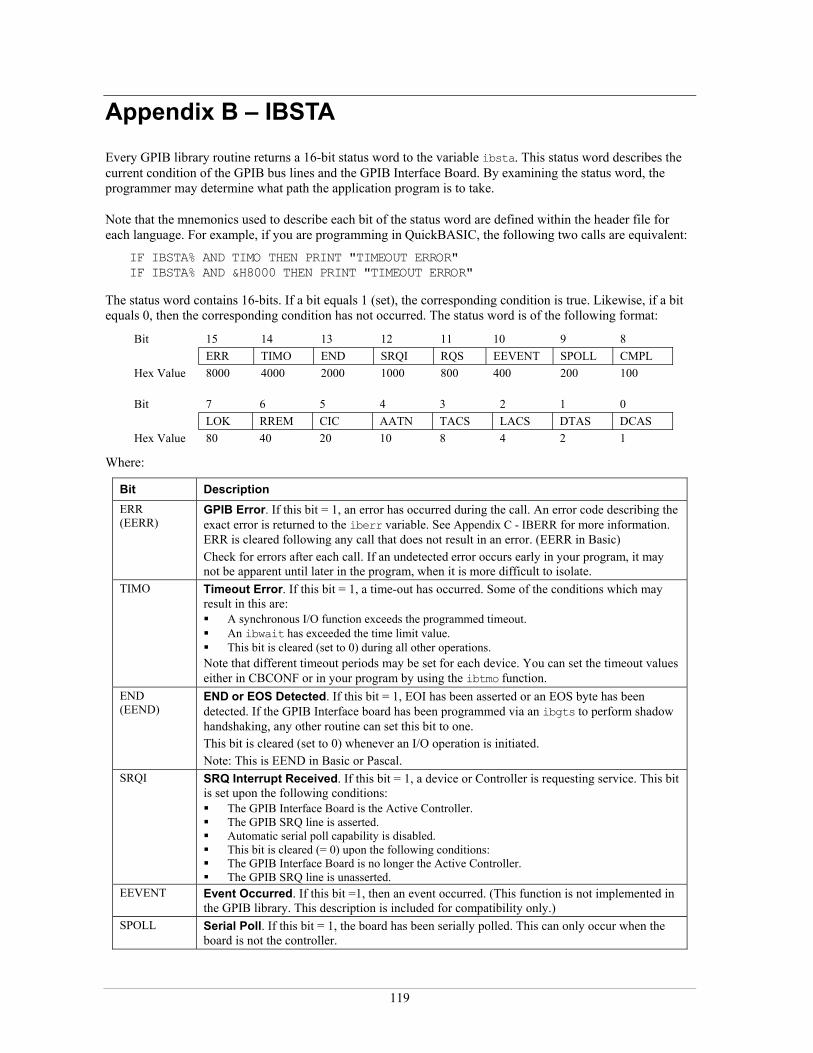
Appendix B – IBSTA
Every GPIB library routine returns a 16-bit status word to the variable ibsta. This status word describes the current condition of the GPIB bus lines and the GPIB Interface Board. By examining the status word, the programmer may determine what path the application program is to take.
Note that the mnemonics used to describe each bit of the status word are defined within the header file for each language. For example, if you are programming in QuickBASIC, the following two calls are equivalent:
IF IBSTA% AND TIMO THEN PRINT "TIMEOUT ERROR" IF IBSTA% AND &H8000 THEN PRINT "TIMEOUT ERROR"
The status word contains 16-bits. If a bit equals 1 (set), the corresponding condition is true. Likewise, if a bit equals 0, then the corresponding condition has not occurred. The status word is of the following format:
Bit 15 14 13 12 11 10 9 8 ERR TIMO END SRQI RQS EEVENT SPOLL CMPL Hex Value 8000 4000 2000 1000 800 400 200 100
Bit 7 6 5 4 3 2 1 0 LOK RREM CIC AATN TACS LACS DTAS DCAS Hex Value 80 40 20 10 8 4 2 1
Where:
Bit Description ERR (EERR)
GPIB Error. If this bit = 1, an error has occurred during the call. An error code describing the exact error is returned to the iberr variable. See Appendix C - IBERR for more information. ERR is cleared following any call that does not result in an error. (EERR in Basic) Check for errors after each call. If an undetected error occurs early in your program, it may not be apparent until later in the program, when it is more difficult to isolate.
TIMO Timeout Error. If this bit = 1, a time-out has occurred. Some of the conditions which may result in this are: A synchronous I/O function exceeds the programmed timeout. An ibwait has exceeded the time limit value. This bit is cleared (set to 0) during all other operations.
Note that different timeout periods may be set for each device. You can set the timeout values either in CBCONF or in your program by using the ibtmo function.
END (EEND)
END or EOS Detected. If this bit = 1, EOI has been asserted or an EOS byte has been detected. If the GPIB Interface board has been programmed via an ibgts to perform shadow handshaking, any other routine can set this bit to one. This bit is cleared (set to 0) whenever an I/O operation is initiated. Note: This is EEND in Basic or Pascal.
SRQI SRQ Interrupt Received. If this bit = 1, a device or Controller is requesting service. This bit is set upon the following conditions: The GPIB Interface Board is the Active Controller. The GPIB SRQ line is asserted. Automatic serial poll capability is disabled. This bit is cleared (= 0) upon the following conditions: The GPIB Interface Board is no longer the Active Controller. The GPIB SRQ line is unasserted.
EEVENT Event Occurred. If this bit =1, then an event occurred. (This function is not implemented in the GPIB library. This description is included for compatibility only.)
SPOLL Serial Poll. If this bit = 1, the board has been serially polled. This can only occur when the board is not the controller.
119
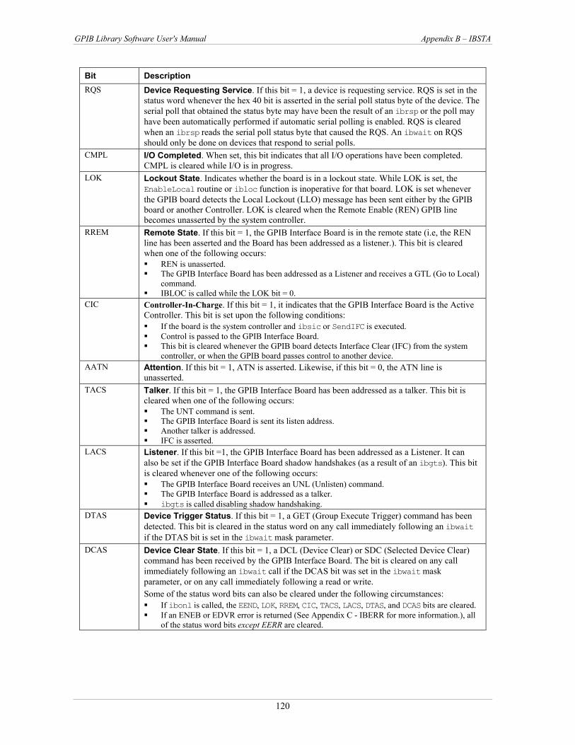
GPIB Library Software User's Manual Appendix B – IBSTA
Bit Description RQS Device Requesting Service. If this bit = 1, a device is requesting service. RQS is set in the
status word whenever the hex 40 bit is asserted in the serial poll status byte of the device. The serial poll that obtained the status byte may have been the result of an ibrsp or the poll may have been automatically performed if automatic serial polling is enabled. RQS is cleared when an ibrsp reads the serial poll status byte that caused the RQS. An ibwait on RQS should only be done on devices that respond to serial polls.
CMPL I/O Completed. When set, this bit indicates that all I/O operations have been completed. CMPL is cleared while I/O is in progress.
LOK Lockout State. Indicates whether the board is in a lockout state. While LOK is set, the EnableLocal routine or ibloc function is inoperative for that board. LOK is set whenever the GPIB board detects the Local Lockout (LLO) message has been sent either by the GPIB board or another Controller. LOK is cleared when the Remote Enable (REN) GPIB line becomes unasserted by the system controller.
RREM Remote State. If this bit = 1, the GPIB Interface Board is in the remote state (i.e, the REN line has been asserted and the Board has been addressed as a listener.). This bit is cleared when one of the following occurs: REN is unasserted. The GPIB Interface Board has been addressed as a Listener and receives a GTL (Go to Local)
command. IBLOC is called while the LOK bit = 0.
CIC Controller-In-Charge. If this bit = 1, it indicates that the GPIB Interface Board is the Active Controller. This bit is set upon the following conditions: If the board is the system controller and ibsic or SendIFC is executed. Control is passed to the GPIB Interface Board. This bit is cleared whenever the GPIB board detects Interface Clear (IFC) from the system
controller, or when the GPIB board passes control to another device. AATN Attention. If this bit = 1, ATN is asserted. Likewise, if this bit = 0, the ATN line is
unasserted. TACS Talker. If this bit = 1, the GPIB Interface Board has been addressed as a talker. This bit is
cleared when one of the following occurs: The UNT command is sent. The GPIB Interface Board is sent its listen address. Another talker is addressed. IFC is asserted.
LACS Listener. If this bit =1, the GPIB Interface Board has been addressed as a Listener. It can also be set if the GPIB Interface Board shadow handshakes (as a result of an ibgts). This bit is cleared whenever one of the following occurs: The GPIB Interface Board receives an UNL (Unlisten) command. The GPIB Interface Board is addressed as a talker. ibgts is called disabling shadow handshaking.
DTAS Device Trigger Status. If this bit = 1, a GET (Group Execute Trigger) command has been detected. This bit is cleared in the status word on any call immediately following an ibwait if the DTAS bit is set in the ibwait mask parameter.
DCAS Device Clear State. If this bit = 1, a DCL (Device Clear) or SDC (Selected Device Clear) command has been received by the GPIB Interface Board. The bit is cleared on any call immediately following an ibwait call if the DCAS bit was set in the ibwait mask parameter, or on any call immediately following a read or write. Some of the status word bits can also be cleared under the following circumstances: If ibonl is called, the EEND, LOK, RREM, CIC, TACS, LACS, DTAS, and DCAS bits are cleared. If an ENEB or EDVR error is returned (See Appendix C - IBERR for more information.), all
of the status word bits except EERR are cleared.
120

Appendix C – IBERR
If the EERR bit in the status word (ibsta) has been set (= 1), an error code describing the exact error is returned to the iberr variable. lists the possible GPIB error codes, the corresponding mnemonic, and a brief explanation. Note that the mnemonics are defined within the header files for each language. This allows you to use the mnemonic in place of the error code value. Detailed explanations of each error and possible solutions are listed after the table.
Table C-1
Table C-1. Error codes Error Code
Decimal Mnemonic
Description
0 EDVR Driver Error 1 ECIC Specified GPIB Interface Board is not the Active Controller 2 ENOL No present listening devices 3 EADR GPIB Interface Board has not been addressed properly 4 EARG Invalid argument specified 5 ESAC Specified GPIB interface board is not the system controller 6 EABO I/O operation aborted (time-out) 7 ENEB Non-existent GPIB board specified 10 EOIP Routine not allowed during asynchronous I/O operation 11 ECAP No capability for operation 12 EFSO File System error 14 EBUS Command byte transfer error 15 ESTB Serial poll status byte lost 16 ESRQ SRQ stuck in ON position 20 ETAB Table problem 247 EINT No interrupt configured on board 248 EWMD (16-bit only) Windows is not in Enhanced mode 249 EVDD (16-bit only) CBGPIB.386 is not installed 250 EOVR (16-bit only) Buffer overflow 251 ESML (16-bit only) Two library calls running simultaneously 252 ECFG Board type does not match GPIB.CFG 253 ETMR (16-bit only) No Windows timers available 254 ESLC (16-bit only) No Windows selectors available 255 EBRK (16-bit only) Ctrl-Break pressed, exiting program
EDVR — Driver error Cause: A board or device is not installed or configured properly. This error is returned when a device or
board that is passed to ibfind cannot be found, or when a board index passed to ibdev cannot be found. ibcntl will contain an error code to help further identify the problem.
Solution: Call ibdev to open a device without using its symbolic name. Configure each board and device using CBCONF before using them as parameters to ibfind. Include the unit descriptor that is returned from ibfind or ibdev as the first parameter in the
function. Verify that the value of the variable before the failing function is not corrupted. ECIC — specified GPIB interface board is not CIC
Cause: Many routines require that the GPIB interface board is the Controller-In-Charge. These include: ibcmd, ibln, ibrpp, Send, Receive, for example. Any routines which manipulate the GPIB ATN, EOI, or REN lines
Solution: Make sure that the GPIB interface board is the Controller-In-Charge
121

GPIB Library Software User's Manual Appendix C – IBERR
ENOL — no listening device(s) Cause: The routine detected no listeners. Solution: Verify the following:
Make sure that a device has been addressed properly. Check that at least two-thirds of the devices on the GPIB bus are turned on, including the
specified device. Make sure that all connections are secure. Verify the device(s) GPIB address. Make sure that the device was properly configured with the CBCONF configuration program.
EADR — GPIB interface board not addressed Cause: The GPIB interface board has not been addressed. Solution: Call ibcmd and address the board.
If you are calling ibgts, with shadow handshaking enabled, call ibcac.
EARG — invalid argument Cause: An invalid parameter has been provided to a routine. Solution: Check syntax and range of parameters. See Chapter 4 GPIB 488.1 Library Reference and Chapter 5
GPIB 488.2 Library Reference. ESAC — board is not the system controller
Cause: Routine requires that the GPIB interface board is the system controller. Solution: Configure the board to be the system controller. Run your configuration utility (CBCONF) or call
ibrsc.
EABO — I/O operation aborted Cause: I/O operation aborted. (time-out) Solution: Check that the device is powered on.
Verify proper cable connections. ENEB — non-existent GPIB board
Cause: GPIB board is not recognized. Solution: Make sure that GPIB board settings and configuration setup parameters agree.
EOIP — function not allowed while I/O is in progress Cause: An illegal call is made during an asynchronous I/O operation. Solution: Only ibstop, ibwait, and ibonl calls are allowed during asynchronous I/O operations. The
driver must be resynchronized by calling one of the following: ibwait (mask contains CMPL) - The driver and application are synchronized. ibstop - The asynchronous I/O is canceled, and the driver and application are synchronized. ibonl - The asynchronous I/O is canceled, the interface is reset, and the driver and application
are synchronized. Re-synchronization is successful if a CMPL is returned to ibsta.
ECAP — no capability for operation Cause: A call attempts to use a capability which is not supported by the GPIB board. Solution: Don't use the call; upgrade your GPIB board
EFSO — file system error Cause: A problem was encountered while performing a file operation. Solution: Verify the following:
Make sure that you specified the correct filename. Check the spelling and the path. If you need more room on the disk, delete some files. Verify that you did not assign a name to a device which is already used by a file (using your
CBCONF configuration program).
122

GPIB Library Software User's Manual Appendix C – IBERR
EBUS — command byte transfer error Cause: A GPIB bus error occurs during a device function. Solution: Determine which device, if any, is abnormally slow to accept commands and fix the problem with
the device. Lengthen the assigned time limit using ibtmo or IBCONF.
ESTB — serial poll status byte(s) lost Cause: One or more serial poll status bytes received during an automatic serial poll was lost. Solution: Call ibrsp more frequently to read the status bytes. Ignore the ESTB error.
Note: This error occurs only during ibrsp functions.
ESRQ — SRQ in "ON" position Cause: A wait for an RQS can not occur because the GPIB SRQ line is ON. Solution: Verify the following:
Ignore the ESRQ until all devices are found. Make sure an ibfind is called to open all devices on the bus capable of asserting SRQ. Test that each device is unasserting SRQ. Check the cabling. Make sure that all devices are attached and the connectors are seated
properly. ETAB — table problem
Cause: There was a problem with a table used in a FindLstn or FindRQS. Solution: If the error occurs during a FindLstn, this is a warning and not an error. Ignore the warning or
make the buffer larger. If the error occurs during a FindRQS, then none of the specified devices are requesting services. Verify that the device list contains the addresses of all on line devices.
EINT — no interrupt level configured Cause: Your routine requires an interrupt and no interrupt level is configured for the board. Solution: Use a routine that doesn’t require an interrupt, or configure an interrupt level.
EWMD — Windows not in enhanced mode (16-bit only) Cause: The Windows GPIB Library can only run in Windows Enhanced Mode, and Windows is currently
running in a different mode. Solution: Restart Windows in enhanced mode, or upgrade to a newer version of Windows.
EVDD — CBGPIB.386 is not installed (16-bit only) The Windows GPIB library requires the CBGPIB.386 device driver to be installed, and it isn't.
Solution: Edit your Windows SYSTEM.INI file. It is normally located in the \windows directory. Add the following entry to the section that begins with [386Enh]
If your software was not installed in the default \gpib directory, change that line to the appropriate directory.
EOVR — Buffer overflow (16-bit only) Cause: Solution: Increase the size of the buffer.
Cause: The GPIB library can only execute one function at a time, and an attempt was made to call a GPIB routine while another routine was still executing. The most common causes are that more than one GPIB program is being executed or that GPIB routines are being called from timer event handlers.
Solution:
A common solution is to use a semaphore variable. In your main code set a variable to some known value before you begin executing GPIB routines, and clear it when you finish. In your timer event handler, only call the GPIB routine if the semaphore is cleared. Refer to the VBDEMO example program's use of the GPIBCallInProgress variable for a demonstration of how to use this technique.
Cause:
device=\gpib\cbgpib.386
A buffer was not large enough to hold the data.
ESML — Library calls running simultaneously (16-bit only)
If more than one GPIB program is running, then stop one of them. If you are calling GPIB routines from within Windows timer event handlers, add code to detect and prevent the problem.
123

GPIB Library Software User's Manual Appendix C – IBERR
ECFG — board type does not match GPIB.cfg Cause: The board type specified in the GPIB.CFG file is different than the installed board. Solution: Run the CBCONF configuration program and set the Board Type to the correct board type.
ETMR — No Windows timers available (16-bit only) Cause: Windows has a limited number of system timers. The GPIB library requested a timer and Windows
reported that there were none left. Solution: Stop any running Windows programs that you are not using.
ESLC — No Windows selectors available (16-bit only) Cause: No memory selectors are available. Solution: Close any open programs to free up more memory.
EBRK — Ctrl-Break pressed, exiting program (16-bit only) Cause: The program was terminated by the user pressing the Control-Break key. Solution: --
124

Measurement Computing Corporation 16 Commerce Blvd.
Middleboro, MA 02346 (508) 946-5100
Fax: (508) 946-9500 E-mail: [email protected]
www. mccdaq.com