gp1/dl6 gsm modem system - delta t … · user manual for the gp1/dl6 gsm modem system gsm-um-1.1...
TRANSCRIPT

User Manual for the
GP1/DL6 GSM Modem System
GSM-UM-1.1
Delta-T Devices

Notices Copyright Copyright © Delta-T Devices 2006 All parts of the GSM System design and documentation are the exclusive copyright of Delta-T Devices Ltd.
CE Conformity Meets the intent of the EMC Directive 89/336/EEC. See GSM-BX1 & GP1-DL6 Network Regulatory Information. PDF in the Product Documentation folder of the Delta-T Software and Manuals CD.
Design Changes Delta-T Devices Ltd reserves the right to change the designs and specifications of its products at any time without prior notice.
User Manual Version: GSM-UM-1.1 Dec 4 2006
Delta-T Devices Ltd Tel: +44 1638 742922 130 Low Road, Burwell Fax: +44 1638 743155
© 2006 Delta-T Devices Ltd Page 2
Cambridge CB25 0EJ email: [email protected] web: www.delta-t.co.uk

© 2006 Delta-T Devices Ltd Page 3
Contents Layout........................................................................................ 4
External connectors and cable glands....................................................................... 5 Introduction............................................................................... 6
Antenna ..................................................................................................................... 6 Logger cabling........................................................................................................... 6 Software .................................................................................................................... 6
Unpacking ................................................................................. 7 Basic GSM Modem Box ............................................................................................ 7 GSM Modem Box (solar power) type GSM-BX1/SP.................................................. 7 GSM Modem Box (internal battery) type GSM-BX1/IB ............................................. 7 GSM Modem Box (without battery) type GSM-BX1/EB ............................................ 7 Accessories ............................................................................................................... 8 Also required for all systems ..................................................................................... 9
Getting started ........................................................................ 10 Set up at your bench first!........................................................................................ 10 Fit a SIM card .......................................................................................................... 10 Install the antenna ................................................................................................... 11 Supply power to the modem.................................................................................... 12 Use of the Timer ...................................................................................................... 12 Configure, Test or Add Text Message to modem .................................................... 13 Create a modem connection in DeltaLINK .............................................................. 16 Install Modem Box ................................................................................................... 17 Install Solar Panel (option) ...................................................................................... 18 Install logger(s) ........................................................................................................ 19 Battery life Considerations....................................................................................... 20
Wiring Diagrams ..................................................................... 21 Wiring scheme for GSM-BX1/SP… Solar Power..................................................... 21 Wiring scheme for Solar Power and Timer .............................................................. 21 Wiring scheme for GSM-BX1EB… External Battery................................................ 22 Wiring scheme for GSM-BX1/ IB…Internal Battery ................................................. 22
Other Documents.................................................................... 23 Specifications ......................................................................... 24
Environmental specifications ................................................................................... 26 Electromagnetic Compatibility (EMC) ...................................................................... 26
Care and Safety....................................................................... 27 Technical Support .................................................................. 27
Terms and Conditions of sale.................................................................................. 27 Service and Spares ................................................................................................. 28 Technical Support.................................................................................................... 28
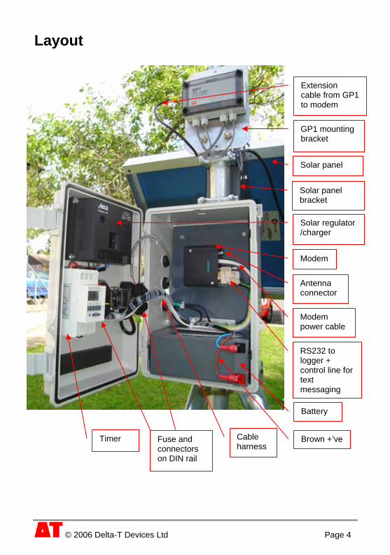
Layout
Extension cable from GP1 to modem
GP1 mounting bracket
Solar panel
Solar panel bracket
Modem
Antenna connector
Modem power cable
RS232 to logger + control line for text messaging
Battery
Brown +’veCable harness
Fuse and connectors on DIN rail
Timer
Solar regulator /charger
© 2006 Delta-T Devices Ltd Page 4

External connectors and cable glands
Cable glands for 1) external antenna, 2) external battery or solar panel and/or 3) control line from logger for triggering text messages
Breather
M8 socket for connecting to
logger(s) via GP1 Network Cabling
© 2006 Delta-T Devices Ltd Page 5
© 2006 Delta-T Devices Ltd Page 6
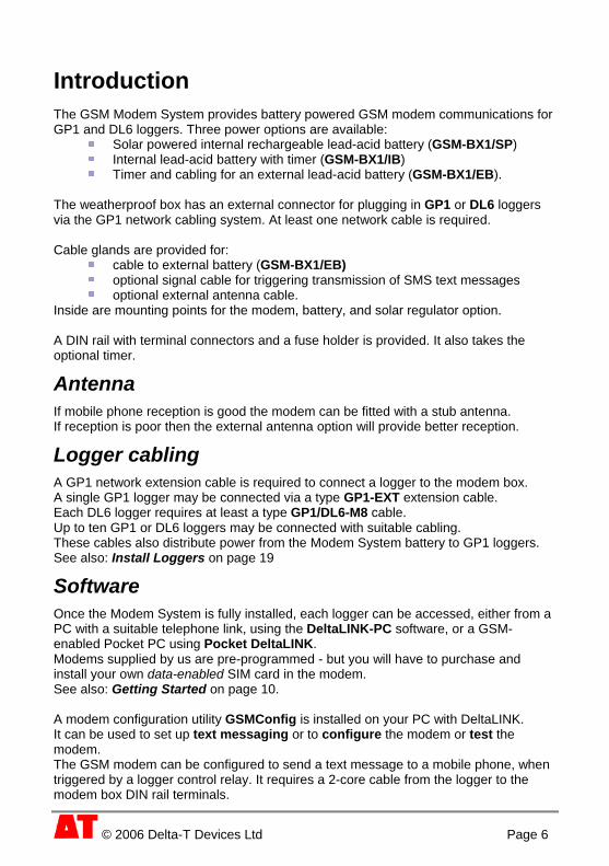
Introduction The GSM Modem System provides battery powered GSM modem communications for GP1 and DL6 loggers. Three power options are available:
Solar powered internal rechargeable lead-acid battery (GSM-BX1/SP) Internal lead-acid battery with timer (GSM-BX1/IB) Timer and cabling for an external lead-acid battery (GSM-BX1/EB).
The weatherproof box has an external connector for plugging in GP1 or DL6 loggers via the GP1 network cabling system. At least one network cable is required. Cable glands are provided for:
cable to external battery (GSM-BX1/EB) optional signal cable for triggering transmission of SMS text messages optional external antenna cable.
Inside are mounting points for the modem, battery, and solar regulator option. A DIN rail with terminal connectors and a fuse holder is provided. It also takes the optional timer.
Antenna If mobile phone reception is good the modem can be fitted with a stub antenna. If reception is poor then the external antenna option will provide better reception.
Logger cabling A GP1 network extension cable is required to connect a logger to the modem box. A single GP1 logger may be connected via a type GP1-EXT extension cable. Each DL6 logger requires at least a type GP1/DL6-M8 cable. Up to ten GP1 or DL6 loggers may be connected with suitable cabling. These cables also distribute power from the Modem System battery to GP1 loggers. See also: Install Loggers on page 19
Software Once the Modem System is fully installed, each logger can be accessed, either from a PC with a suitable telephone link, using the DeltaLINK-PC software, or a GSM-enabled Pocket PC using Pocket DeltaLINK. Modems supplied by us are pre-programmed - but you will have to purchase and install your own data-enabled SIM card in the modem. See also: Getting Started on page 10. A modem configuration utility GSMConfig is installed on your PC with DeltaLINK. It can be used to set up text messaging or to configure the modem or test the modem. The GSM modem can be configured to send a text message to a mobile phone, when triggered by a logger control relay. It requires a 2-core cable from the logger to the modem box DIN rail terminals.

Unpacking Check your contents against your order and any packing lists. All GSM Modem Box Systems include the Basic GSM Modem Box:
Basic GSM Modem Box Siemens TC35i modem Plastic Modem Box, sealed to IP66, fitted with:
GP1 network cable connector (5 pole M8 female), 3 cable glands for: external battery or solar power cable, optional signal cable for triggering transmission of SMS text messages, and optional external antenna cable, PTFE breather, DIN rail with terminals and 3A fuse holder, Desiccant bag.
PC-modem serial cable GSM-RS-DB9 to configure the modem from a PC.
GSM Modem Box (solar power) type GSM-BX1/SP In addition to the Basic GSM Modem Box, this includes:
30W solar panel Solar Panel Mounting Bracket and U-bolts Solar regulator/charger 10Ah sealed lead acid battery. 2 m power cable with flying leads
GSM Modem Box (internal battery) type GSM-BX1/IB In addition to the Basic Modem Box, this includes:
10Ah sealed lead acid battery. Timer
GSM Modem Box (without battery) type GSM-BX1/EB In addition to the Basic Box and Modem, this includes:
Timer does not includeThis a battery or external battery cable.
© 2006 Delta-T Devices Ltd Page 7
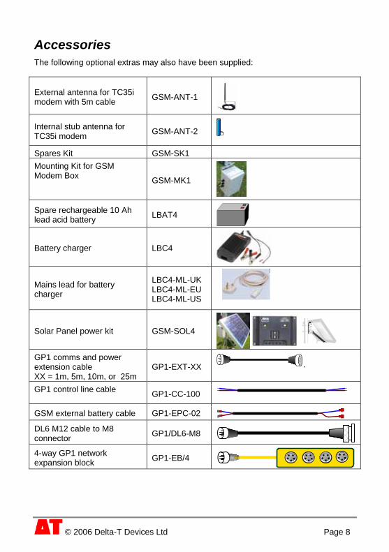
Accessories The following optional extras may also have been supplied:
External antenna for TC35i modem with 5m cable GSM-ANT-1
© 2006 Delta-T Devices Ltd Page 8
Internal stub antenna for TC35i modem GSM-ANT-2
Spares Kit GSM-SK1 Mounting Kit for GSM Modem Box
GSM-MK1
Spare rechargeable 10 Ah lead acid battery LBAT4
Battery charger LBC4
Mains lead for battery charger
LBC4-ML-UK LBC4-ML-EU LBC4-ML-US
Solar Panel power kit GSM-SOL4
GP1 comms and power extension cable . XX = 1m, 5m, 10m, or 25m
GP1-EXT-XX
GP1 control line cable GP1-CC-100
GSM external battery cable GP1-EPC-02 DL6 M12 cable to M8 connector GP1/DL6-M8
4-way GP1 network expansion block GP1-EB/4
© 2006 Delta-T Devices Ltd Page 9
Also required for all systems You will also need to provide:
Data enabled SIM card from a local mobile phone service provider GP1/DL6 extension and/or network cable(s) for your logger(s) GP1 and/or DL6 logger(s) running firmware v1.30 or later PC with a telephone modem, running DeltaLINK-PC v2.2 or later
See also the Accessories on page 8.
To obtain the latest DeltaLINK version Link to http://delta-t.co.uk/software-download.html.
To Upgrade DeltaLINK-PC firmware To upgrade your firmware, from the PC Start menu select Programs, DeltaLINK-PC, Firmware Upgrade, and follow the on-screen instructions.
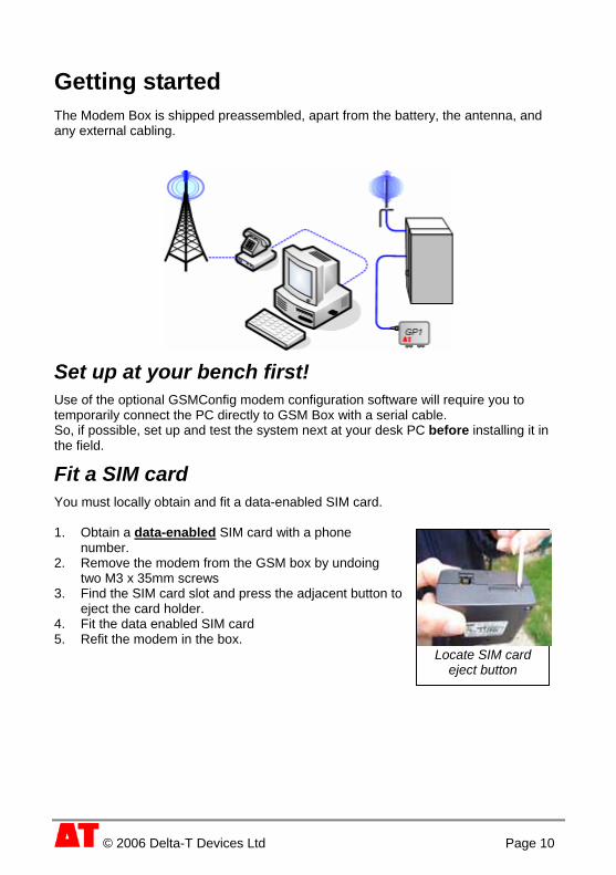
Getting started The Modem Box is shipped preassembled, apart from the battery, the antenna, and any external cabling.
Set up at your bench first! Use of the optional GSMConfig modem configuration software will require you to temporarily connect the PC directly to GSM Box with a serial cable. So, if possible, set up and test the system next at your desk PC before installing it in the field.
Fit a SIM card You must locally obtain and fit a data-enabled SIM card. 1. Obtain a data-enabled
© 2006 Delta-T Devices Ltd Page 10
SIM card with a phone number.
2. Remove the modem from the GSM box by undoing two M3 x 35mm screws
3. Find the SIM card slot and press the adjacent button to eject the card holder.
4. Fit the data enabled SIM card 5. Refit the modem in the box. Locate SIM card eject button
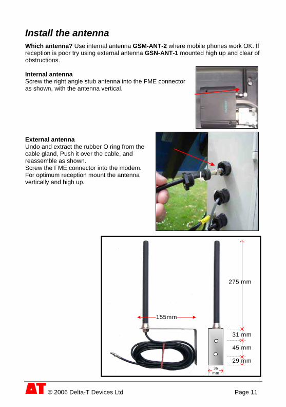
Install the antenna Which antenna? Use internal antenna GSM-ANT-2 where mobile phones work OK. If reception is poor try using external antenna GSN-ANT-1 mounted high up and clear of obstructions. Internal antenna Screw the right angle stub antenna into the FME connector as shown, with the antenna vertical. External antenna Undo and extract the rubber O ring from the cable gland, Push it over the cable, and reassemble as shown. Screw the FME connector into the modem. For optimum reception mount the antenna vertically and high up.
155mm
31 mm
45 mm
29 mm36
mm
275 mm
© 2006 Delta-T Devices Ltd Page 11

Supply power to the modem The modem will need power before you can configure, test or use it. Unpack and fit the internal battery or your own external battery. For wiring schematics - see Wiring Diagrams on page 21
Use of the Timer If using the Timer, temporarily set it ON, to provide continuous power when setting up or testing the Siemens GSM modem. To turn the power on, toggle the Manual button on the Timer until the red LED lights.
About the Timer Battery power is wired via the Timer to provide intermittent power to the modem. Chose when and for how long you would like to communicate with loggers, e.g. once per day for one hour from 14:00. See also Battery Life Considerations on page 20 For wiring instructions see the diagram on the side of the Timer. For programming instructions see the separate DIN rail Timer Instruction Manual. Notes: The timer may also be used with the solar panel – possibly of value in regions where sunlight is insufficient for your needs. Text messaging cannot occur when modem power is off. The timer is itself powered from the GSM modem battery but also has its own battery back-up. The power distribution at the DIN rail is also configured to provide continuous external power for GP1 loggers. You may disable this if you like. See: How to disconnect the external power supply to GP1 loggers on page 19
© 2006 Delta-T Devices Ltd Page 12

Configure, Test or Add Text Message to modem This section describes how to use the GSM modem configuration software GSMConfig to:
Configure the modem Test your modem connection Add a text message for sending to a mobile phone
Note: If your modems is supplied by Delta-T it will be preconfigured and ready to use. If you have no need for the text messaging option then you may skip this section and go to “Create a modem connection in DeltaLINK” on page 16.
To configure the modem: You will need a PC with RS232 serial port or USB RS232 adapter. 1. Disconnect the modem from serial cable in the GSM System box and connect it
directly to your PC serial port using PC-modem serial cable GSM-RS-DB9.
2. From the PC Start menu select Programs, DeltaLINK-PC, GSMConfig util . ity
GSM Modem will be used with to DL6/GP1. ort that you are using.
3. Set 4. Set GSM modem is connected to the PC serial p5. Click Configure modem now.
en instructions. Click Help for additional on-scre
© 2006 Delta-T Devices Ltd Page 13
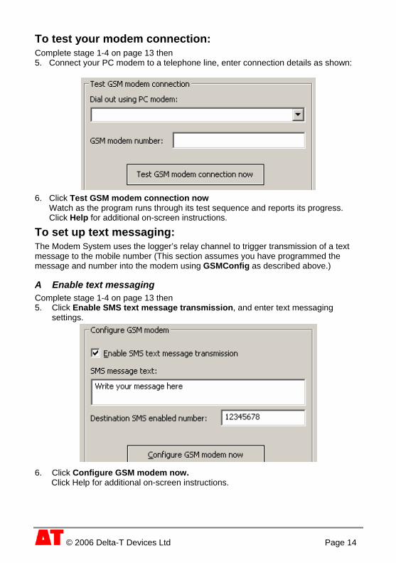
To test your modem connection: Complete stage 1-4 on page 13 then 5. Connect your PC modem to a telephone line, enter connection details as shown:
6. Click Test GSM modem connection now Watch as the program runs through its test sequence and reports its progress. Click Help for additional on-screen instructions.
To set up text messaging: The Modem System uses the logger’s relay channel to trigger transmission of a text message to the mobile number (This section assumes you have programmed the message and number into the modem using GSMConfig as described above.)
A Enable text messaging Complete stage 1-4 on page 13 then 5. Click Enable SMS text message transmission, and enter text messaging
settings.
6. Click Configure GSM modem now. Click Help for additional on-screen instructions.
© 2006 Delta-T Devices Ltd Page 14

B Test the text message configuration 1. Reconnect the GSM modem to the Modem System cable,
and ensure it’s powered up. 2. Briefly connect together the two DIN rail terminals (green and yellow wires)
e.g. with a piece of bent wire. This simulates a contact closure in the logger relay. Within a minute or two you should receive a text message at your mobile number.
C Program the logger’s relay Refer to the GP1 or DL6 Quick Start Guide and DeltaLINK online Help for information about programming the logger. In a Standard GP1 or DL6 program, enable the Alarm relay or Advanced control relay option, and enter details in the Alarm or Control tab, and click on Apply to send the program to the logger.
D Connect the logger’s relay Connect the logger relay channel to the text message control lines (green and yellow) in the modem box via 2 black DIN rail terminals as shown, using a 2-core signal cable.
Modem
Text message control
Battery
Logger relay
2-wire control line from logger - signals modem to send text message
lid box
Extension cable (RS232 + power)
E Test the program and relay connection: Before starting logging: 1. Connect the logger to your PC, start DeltaLINK and select the Sensors window 2. Connect up and place sensors in conditions which should cause a text message
transmission. You should hear the relay click and receive a text message shortly after.
© 2006 Delta-T Devices Ltd Page 15
© 2006 Delta-T Devices Ltd Page 16
Notes on Text Messaging behaviour • The modem will not send text messages if it is not powered!
e.g. if using the Timer and the Timer is off.
• GP1 and DL6 logger’s have one relay only, so if you use the relay to trigger text messaging you will not be able to use it for other control purposes – unless you wish to receive a text message each time the relay switches.
• When logging, the logger only checks the condition that controls the relay when a logging interval arrives. Normally, this system sends a single text message each time the condition becomes true. To send the same message repeatedly for as long as the condition remains true, select the Advanced control relay option and select the Enable pulsing option in the Control tab.
• You can’t send different messages for different alarm conditions.
Create a modem connection in DeltaLINK Create a connection in DeltaLINK for each logger connected to the Modem System. 1. Connect a logger to the Modem System using a suitable extension cable.
See also page 19 2. Start DeltaLINK and click Cancel when it tries to connect to a logger. 3. Select File, New, Connection. 4. In the Connection dialog, click New… 5. In the Connection Properties dialog, enter a descriptive name for your
connection, e.g. “GP1 logger on 07890 123456” and select Telephone modem in the Connect to logger using list.
6. If you are intending to network more than one logger to the Modem System, enable Networked, and enter the logger’s type and serial number.
7. In the Details tab, select the name of your PC modem, enter the telephone number of your Modem System, and click OK.
8. DeltaLINK will now dial and connect to your logger. You can later select the connection that you have just created to connect to the same logger again.
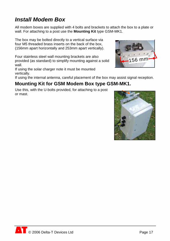
Install Modem Box All modem boxes are supplied with 4 bolts and brackets to attach the box to a plate or wall. For attaching to a post use the Mounting Kit type GSM-MK1. The box may be bolted directly to a vertical surface via
156 mm
four M5 threaded brass inserts on the back of the box, (156mm apart horizontally and 253mm apart vertically). Four stainless steel wall mounting brackets are also provided (as standard) to simplify mounting against a solid wall. If using the solar charger note it must be mounted vertically. If using the internal antenna, careful placement of the box may assist signal reception.
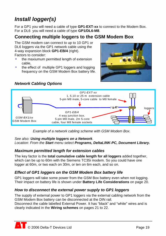
Mounting Kit for GSM Modem Box type GSM-MK1. Use this, with the U-bolts provided, for attaching to a post or mast.
© 2006 Delta-T Devices Ltd Page 17

Install Solar Panel (option) Warnings Observe the warnings given in the solar panel guide and the Solsum solar charge controller. Cover the panel before wiring it up to prevent electric shocks from bare wires. Observe the polarity requirement of both the solar panel and the Solsum regulator. Note the Solsum regulator provides diode and fuse protection for the panel but is not protected from the wrong polarity. Showing a GP1 logger (at top), solar panel
and GSM Modem Box, each fixed to a post using U-bolts and mounting brackets.
Mount the Solsum solar charge controller vertically. This usually means ensure the Modem Box is vertical.
Considerations when mounting solar panels
Equator
Observe the warnings above, of course. Tilt it to the angle of latitude, or in high latitudes up to 10 degrees more, to capture more light early in the day. You may wish to place the panel to shield your GSM Modem Box and or logger from the sun. Do not site an air temperature or RH sensor directly above the panel, rising hot air may distort ambient readings.
Assembly Mounting bracket, bolts, cabling and U bolts are provided
Assemble the two halves of the solar panel bracket with the bolts provided. See also: SX20-40 Single Module Mounting Kit
Attach that to a mast (not provided) Add the solar panel,
See also: Solar panel Instruction Sheet and a separate Appendix and Wiring diagram and Warnings on back of Solar Panel.
Cover it to exclude light. Attach the power cable from the Solsum solar charger/regulator to the screw
terminals on the back of the solar panel, as indicated in the wiring diagram on the back of the solar panel. (Brown=positive, blue=negative) See also: Solar Charge Controllers Instructions for the Solsum 6.6c
© 2006 Delta-T Devices Ltd Page 18
Install logger(s) For a GP1 you will need a cable of type GP1-EXT-xx to connect to the Modem Box. For a DL6 you will need a cable of type GP1/DL6-M8.
Connecting multiple loggers to the GSM Modem Box The GSM modem can connect to up to 10 GP1 or DL6 loggers via the GP1 network cable using the 4-way expansion block GP1-EB/4 (right). Factors to consider:
the maxiumum permitted length of extension cable,
the effect of multiple GP1 loggers and logging frequency on the GSM Modem Box battery life.
Network Cabling Options
Example of a network cabling scheme with GSM Modem Box.
GSM-BX1/xxGSM Modem Box
GP1-EXT-xx1, 5,10 or 25 m extension cable
5-pin M8 male, 5-core cable to M8 female
GP1-EB/44 way junction box.
5-pin M8 male, 2m 5-core cable, four M8 female sockets
loggers
See also: Using multiple loggers on a Network. Location: From the Start menu select Programs, DeltaLINK-PC, Document Library.
Maximum permitted length for extension cables The key factor is the total cumulative cable length for all loggers added together, which can be up to 60m with the Siemens TC35i modem. So you could have one logger at 60m, or two each on 30m, or ten on 6m each, and so on.
Effect of GP1 loggers on the GSM Modem Box battery life GP1 loggers will take some power from the GSM Box battery even when not logging. Their impact on battery life is shown under Battery Life Considerations on page 20.
How to disconnect the external power supply to GP1 loggers The supply of external power to GP1 loggers via the external cabling network from the GSM Modem Box battery can be disconnected at the DIN rail. Disconnect the cable labelled External Power. It has “black” and “white” wires and is clearly indicated in the Wiring schemes on pages 21 to 22.
© 2006 Delta-T Devices Ltd Page 19

Battery life Considerations
modem acitivity/day4 10 min 20 min 10 min 20 min
Loggers5 logging
frequency0 n/a 21 19 97 571 1/hr 21 18 89 551 1/min 20 17 71 47
10 1/hr 18 16 53 3910 1/min 12 11 21 19
Data on demand2 2/24hr access slot3
Days Without Sun1
This table may help you judge how frequently to log readings and download data. These are approximate figures; performance will depend on local factors. Notes 1: Number of days the 10Ahr battery in the GSM Modem Box may last before it needs recharging.
2It assumes 0.7 sun-hours (kilowatt-hrs/m /day) typical for mid Scotland See also http://www.solar4power.com/map11-global-solar-power.html for maps of solar insolation. Each logger is assumed connected to 2 ML2 sensors each taking 20 mA when read. 2: Modem and GP1 external cabling network continuously powered i.e. not using a timer. 3: Assumes timer is configured so that the modem is powered for 2 hours in every 24. External GP1 cabling network is powered continuously. 4: One day's worth of GP1 data (logged every 1sec) should download via GSM (i.e. at 9600 baud) in under 7 minutes. A full GP1 may take 26 minutes. 5: Number of GP1 loggers connected to the GSM Modem Box which are taking external power from the GSM Modem battery. GP1 loggers take their power from the highest available voltage source. An external 12V battery will always be higher than their internal battery. DL6 loggers cannot take external power and so have no impact. External power to the GP1 loggers via the extension cabling may be disabled at the DIN rail in the Modem Box, leaving the loggers to rely on their internal batteries
© 2006 Delta-T Devices Ltd Page 20

Wiring Diagrams Wiring scheme for GSM-BX1/SP… Solar Power
Modem
GP1
yello
wgr
een
Battery
brow
nbl
uebr
own
blue
brow
nbl
ue
whi
te
blac
k
blue
an d
bla
ck
oran
ge
Modem power
3A Fuse
7.5A Fuse
Text message controlExternal power
Wiring scheme for Solar Power and Timer
Modem
GP1
Battery
Modem power
yello
wgr
een
blac
kre
d
blue
blac
k
3A Fuse
blac
k
whi
tered
brow
nbr
own
blue
red
oran
ge
brow
n
bluered
blue
and
bla
ck
Timer
7.5A Fuse
Text message controlExternal power
© 2006 Delta-T Devices Ltd Page 21

Wiring scheme for GSM-BX1/EB… External Battery
ModemModem
GP1-EPC-02External battery cable
Text message control
Modem power
Battery
red
red
red
red
oran
ge
blac
k an
d bl
ue
yello
wgr
een
blac
kre
d
whi
te
blac
k
brow
nre
d
Blue
and
bla
ck
Timer
External power
Wiring scheme for GSM-BX1/ IB…Internal Battery
© 2006 Delta-T Devices Ltd Page 22
Modem
Text message control
Battery
Modem power
yello
wgr
een
blac
kre
d
whi
te
blac
k
brow
nre
d
Blue
and
bla
ck
red
red
red
red
oran
ge
blac
k an
d bl
ue
3A Fuse
Timer
External power

Other Documents
DeltaLINK Library Documents
In DeltaLINK-PC Document Library In particular see: GP1 Network Quick Start Guide See also the Delta-T Software and Manuals CD Other manufacturers The following documents and instructions are supplied with individual system components by the respective manufacturers (and may change without notice). Solar Charge Controllers supplied with Solsum 6.6c SX20-40 Single Module Mounting Kit Instructions SM-421A Issued with solar panel bracket. Instruction Sheet and a separate Appendix issued with Solar Panel Wiring diagram on back of Solar Panel. DIN Rail Timer Instruction Manual supplied with digital Timer.
© 2006 Delta-T Devices Ltd Page 23

© 2006 Delta-T Devices Ltd Page 24
Specifications GSM Modem Box (solar power) GSM-BX1/SP
Solar powered Siemens TC35i terminal modem + in box with battery. 30W solar panel with mounting bracket, 2 m cable via solar regulator to 10Ah sealed lead acid battery, mounted with modem in plastic box (sealed to IP66, flame resistant to UL94-5VA, UV stabilised), fitted with 5 pin M8 female connector and cable harness for GP1 and DL6 loggers, 3 cable glands for (1) optional GP1 relay-modem control signal for text messages, (2) external solar panel (3) optional external modem antenna, and breather for battery outgassing. DIN rail and terminals. Desiccant bag. 2m modem configuration cable GSM-RS-DB9. NB Antenna, type GSM-ANT-1 (external) or GSM-ANT-2 (internal) must be ordered separately. Does not include mounting post or mast for solar panel
GSM Modem Box (int battery) GSM-BX1/IB
Siemens TC35i terminal modem in box with 10Ah sealed lead acid battery with timer (note 2) to preserve battery life. Mounted in plastic box (sealed to IP66, flame resistant to UL94-5VA, UV stabilised), fitted with 5 pin M8 female connector and cable harness for GP1 and DL6 loggers, 3 cable glands for (1) optional GP1 relay-modem control signal for text messages, (2) optional external solar panel (3) optional external modem antenna, and breather disc for battery outgassing. DIN rail with terminals and 3A fuse. Desiccant bag. 2m modem configuration cable GSM-RS-DB9. NB Antenna, type GSM-ANT-1 (external) or GSM-ANT-2 (internal) must be ordered separately.
GSM Modem Box (without batt) GSM-BX1/EB
Siemens TC35i terminal modem in box with timer (note 2) to preserve external battery life. Mounted in plastic box (sealed to IP66, flame resistant to UL94-5VA, UV stabilised), fitted with 5 pin M8 female connector and cable harness for GP1 and DL6 loggers, 3 cable glands for (1) optional GP1 relay-modem control signal for text messages, (2) external battery (3) optional external modem antenna, and breather for battery outgassing. DIN rail with terminals and 3A fuse. Desiccant bag. 2m modem configuration cable GSM-RS-DB9. NB Antenna, type GSM-ANT-1 (external) or GSM-ANT-2 (internal) must be ordered separately. See also: External battery cable (optional accessory)
Note 1: Antennae
NB Antenna, type GSM-ANT-1 (external) or GSM-ANT-2 (internal) must be ordered separately - for Siemens TC35i modem, FME connector. For use in areas where mobile phones work OK. If reception is poor try using external antenna with ground plane mounted high up and clear of obstructions

© 2006 Delta-T Devices Ltd Page 25
Note2: Timer
Programmable digital 7-day timer with LCD. Prolongs battery life by only turning on modem when needed. Turn on modem just once a week or up to 8 times a day, and for durations of 1 minute to 24 hours. Lithium battery for internal backup. Operates from -10 to +55C.
Note 3: GP1 Extension Cabling
GP1 cabling extension system connects to the modem box. It permits serial comms with multiple GP1 and DL6 loggers, and also supplies power but ONLY to GP1 loggers, not DL6s. Minimum cable requirement for GP1 is 1m extension cable. Minimum cable requirement for DL6 is 1.5m M8 to M12 DL6 comms cable type GP1/DL6-M8
Note 4: Modem Configuration Software
All modem systems, GP1 and DL6 loggers are supplied with modem configuration software on CD, (also available from our website). To configure your modem you will need modem configuration cable GSM-RS-DB9.
Note 5: Text messaging
The cable harness includes 2 leads, green and yellow, connected to DIN rail terminals for triggering GSM modem text messaging via a logger relay. To use it the user needs to supply an external 2-core signal cable from logger to modem box.
Note 6 Mounting
The box may be bolted directly to a vertical surface via four M5 threaded brass inserts on the back of the box, (156mm apart horizontally and 253mm apart vertically). In addition four stainless steel wall mounting brackets & bolts are provided to simplify mounting against a solid wall. For attaching to a post you need the Mast Mounting Accessory.
Internal antenna for TC35i modem GSM-ANT-2
Quad band right angle stub mount antenna for Siemens TC35i terminal modem, FME connector. For use in areas where mobile phones work OK.
External antenna for TC35i modem GSM-ANT-1
External quad band GSM modem aerial with wall mounting bracket and 5m coaxial cable, for remote mounting of antenna, FME female connector on cable for TC35i modem. For use in areas where mobile phone reception may be more difficult.
Mounting kit for GSM Modem Box GSM-MK1
Fixings for mounting GSM Modem Box onto tubular masts or poles.
Spares kit for GSM Modem Box GSM-SK1
3 off 3A fuses for DIN rail. 3 off 7.5A fuses for charger/regulator. 2x 25 gm activated clay desiccant bags, 50cm spiral wrap, 5 cable ties. Spare DIN rail cable, 3 blanking plugs for cable glands.

© 2006 Delta-T Devices Ltd Page 26
Rechargeable battery LBAT4
12V 10Ah sealed lead acid battery with spade terminals. Supplied as standard with GSM-BX1/IB and GSM-BX1/SP Modem Box.
Battery charger for LBAT4 LBC4
Mains battery charger for 10Ah lead acid battery. Input voltage range 100 -240V AC 3A. For indoor use only. NB Suitable mains connection lead must be ordered separately.
Solar panel for GSM modem box GSM-SOL4
30W solar panel with mounting kit including U-clamps, regulator/charger and cabling for connection to GSM Modem Box. Supplied as standard with GSM-BX1/SP Modem Box. NB Does not include mounting post or mast.
Environmental specifications
Min °C
Max °C
IP rating Notes
GSM Box PBT/PC blend, UV stabilised
-40 70 IP66 Protected against dust and temporary flooding
TC35i modem -20 55 IP40 5-80% RH non condensing Lead acid battery
Charge 0 40 Discharge -15 50
Storage -15 40
25-85%RH
Timer -10 55 None Indoor use only Solar Panel -40 85 IP54 Junction box IP54 Solar charger/regulator -25 50 IP22 Extension Cabling
Static -30 90 IP68 Black PUR cable when flexing -5 90 IP68
Electromagnetic Compatibility (EMC) This product meets the intent of the EMC Directive 89/336/EEC. For a certificate of conformity see: GSM-BX1 & GP1-DL6 Network Regulatory Information.pdf in the Product Documentation folder of the Delta-T Software and Manuals CD.
© 2006 Delta-T Devices Ltd Page 27
Care and Safety Batteries Any external lead acid batteries (i.e. external to any data logger) should have an in-line 3A fuse to protect the GP1 network extension cables. Only use one external battery. The GSM modem, including any GP1 network should never have more than one battery connected (one may be present in the GSM modem box!) Only use our approved lead acid batteries (which minimise outgassing) in the GSM box. Other lead acid batteries should be mounted together with the regulator/charger in a separate well-ventilated enclosure provided by the user. Do not charge any external battery (including one in the GSM modem box) via any of the M8 to M8 5-core extension cables (to protect them from any accidental short circuit currents). Do not power the GSM modem via any M8 to M8 5-core extension cable (The modem may use 2-3A on start up).
Solar power To prevent shocks cover the solar panel before connecting or disconnecting wiring. The solar regulator/charger must be installed vertically for correct operation. The solar panel wires MUST have the correct polarity (brown + and blue -)
Desiccant A desiccant bag is provided with the GSM box to buffer humidity changes inside the box and prevent condensation. Replace or regenerate this annually.
Technical Support Terms and Conditions of sale Our Conditions of Sale (ref: COND: 1/00) set out Delta-T's legal obligations on these matters. The following paragraphs summarise Delta-T's position but reference should always be made to the exact terms of our Conditions of Sale, which will prevail over the following explanation. Delta-T warrants that the goods will be free from defects arising out of the materials used or poor workmanship for a period of twelve months from the date of delivery. Delta-T shall be under no liability in respect of any defect arising from fair wear and tear and the warranty does not cover damage through misuse or inexpert servicing, or other circumstances beyond our control. If the buyer experiences problems with the goods they shall notify Delta-T (or Delta-T’s local distributor) as soon as they become aware of such problem. Delta-T may rectify the problem by supplying replacement parts free of charge, or by repairing the goods free of charge at Delta-T's premises in the UK, during the warranty period. If Delta-T requires that goods under warranty be returned to them from overseas for repair, Delta-T shall not be liable for the cost of carriage or for customs clearance in

© 2006 Delta-T Devices Ltd Page 28
respect of such goods. However, we much prefer to have such returns discussed with us in advance and we may, at our discretion, waive these charges. Delta-T shall not be liable to supply products free of charge or repair any goods where the products or goods in question have been discontinued or have become obsolete, although Delta-T will endeavour to remedy the buyer’s problem. Delta-T shall not be liable to the buyer for any consequential loss, damage or compensation whatsoever (whether caused by the negligence of the Delta-T, our employees or distributors or otherwise) which arise from the supply of the goods and/or services, or their use or resale by the buyer. Delta-T shall not be liable to the buyer by reason of any delay or failure to perform our obligations in relation to the goods and/or services, if the delay or failure was due to any cause beyond the Delta-T’s reasonable control.
Service and Spares Users in countries that have a Delta-T Distributor or Technical Representative should contact them in the first instance. Spare parts for our own instruments can be supplied from our works. These can normally be despatched within a few working days of receiving an order. Spare parts and accessories for sensors or other products not manufactured by Delta-T may have to be obtained from our supplier and a certain amount of additional delay is inevitable. No goods or equipment should be returned to Delta-T without first obtaining the agreement of Delta-T or our distributor. On receipt at Delta-T, the goods will be inspected and the user informed of the likely cost and delay. We normally expect to complete repairs within a few working days of receiving the equipment. However, if the equipment has to be forwarded to our original supplier for specialist repairs or recalibration, additional delays of a few weeks may be expected.
Technical Support Technical Support is available on Delta-T products and systems. Users in countries that have a Delta-T Distributor or Technical Representative should contact them in the first instance. Technical Support questions received by Delta-T will be handled by our Tech Support team. Your initial enquiry will be acknowledged immediately with a “T number” and an estimate of time for a detailed reply. Make sure to quote our T number subsequently so that we can easily trace any earlier correspondence. In your enquiry, always quote instrument serial numbers, software version numbers, and the approximate date and source of purchase where these are relevant.
Contact DetailsTech Support Team Delta-T Devices Ltd 130 Low Road, Burwell, Cambridge CB25 0EJ, U.K.
Tel: +44 (0) 1638 742922 Fax: +44 (0) 1638 743155 email: [email protected]: www.delta-t.co.uk

© 2006 Delta-T Devices Ltd Page 29
Index antenna, 9, 13 Antenna, 6 Batteries, 30 battery, 9 Battery charger, 9 battery life, 21 Battery life, 23 cable glands, 5 Cable glands, 6 CE, 2 connectors, 5 Contact, 31 control line cable, 9 Copyright, 2 DeltaLINK, 18 DeltaLINK-PC, 6, 11 Desiccant, 30 DIN, 6 DL6 M12 cable, 9 EMC, 29 Environmental, 29 expansion block, 10 extension cable, 6, 9 External antenna, 13 external battery cable, 9 Firmware Upgrade, 11 GP1 network cable, 21 GP1/DL6-M8, 6, 21 GP1-CC-100, 9 GP1-EB/4, 10, 21 GP1-EPC-02, 9 GP1-EXT, 6 GP1-EXT-xx, 21 GP1-EXT-XX, 9 GSM-ANT, 9 GSM-ANT-1, 9 GSM-BX1/EB, 8 GSM-BX1/IB, 8 GSM-BX1/SP, 8 GSMConfi, 15 GSMConfig, 6, 15
GSM-MK1, 9, 19 GSM-RS-DB9, 15 GSM-SK1, 9 GSM-SOL4, 9 Internal antenna, 13 Layout, 4 LBAT4, 9 LBC4, 9 logger
install, 21 modem, 14, 15
how to configure, 15 Modem Box, 8 Mounting Kit, 9, 19 Network Cabling Options, 21 PC-modem serial cable, 15 Pocket DeltaLINK, 6 power, 14 relay, 17 Service and Spares, 31 Siemens TC35i, 8 SIM, 12 SIM card, 11 Solar Charge Controllers, 26 solar panel, 8 Solar Panel
installation, 20 Solar Panel power kit, 9 Solar power, 30 Solsum regulator, 20 Spares Kit, 9 Technical Support, 30 test modem connection, 16 text messaging, 6, 16 Text Messaging behaviour, 18 Timer, 14 Timer Instruction Manual, 26 Upgrade DeltaLINK, 11 USB RS232, 15 Using multiple loggers, 21