governor ppt
DESCRIPTION
governor ppt by faizTRANSCRIPT

GOVERNOR
PRESENTED BY:- FAIZ AKRAM
ROLL NO:-120106096
GOVERNOR
The function of a governor is to regulate the mean speed of an engine, when there are variations in the load .when the load on an engine increases its speed decreases. And when the load on the engine decreases its speed increases when the load decreases, and the governor decreases the supply of working.
There are two types of governor
1. Centrifugal governor 2. Inertia governor

INERTIA GOVERNOR
This works on a different principle. The governor balls are arranged so that the inertia forces caused by angular acceleration or retardation of the governor shaft tend to alter their positions. The amount of the displacement of the balls is controlled by springs. The advantage of this type of governor is that the positions of the balls are affected by the rate of change of speed of the governor shaft
CENTRIFUGAL GOVERNER
The centrifugal governors are based on the balancing of centrifugal force on the rotating balls by an equal and opposite radial force known as the controlling force. It consists of two balls of equal mass, which are attached to the arms as shown in Fig. 1.1 These balls are known as governor balls or fly balls. The upper ends of the arms are pivoted to the spindle, so that the balls may rise up or fall down as they revolve about the vertical axis.
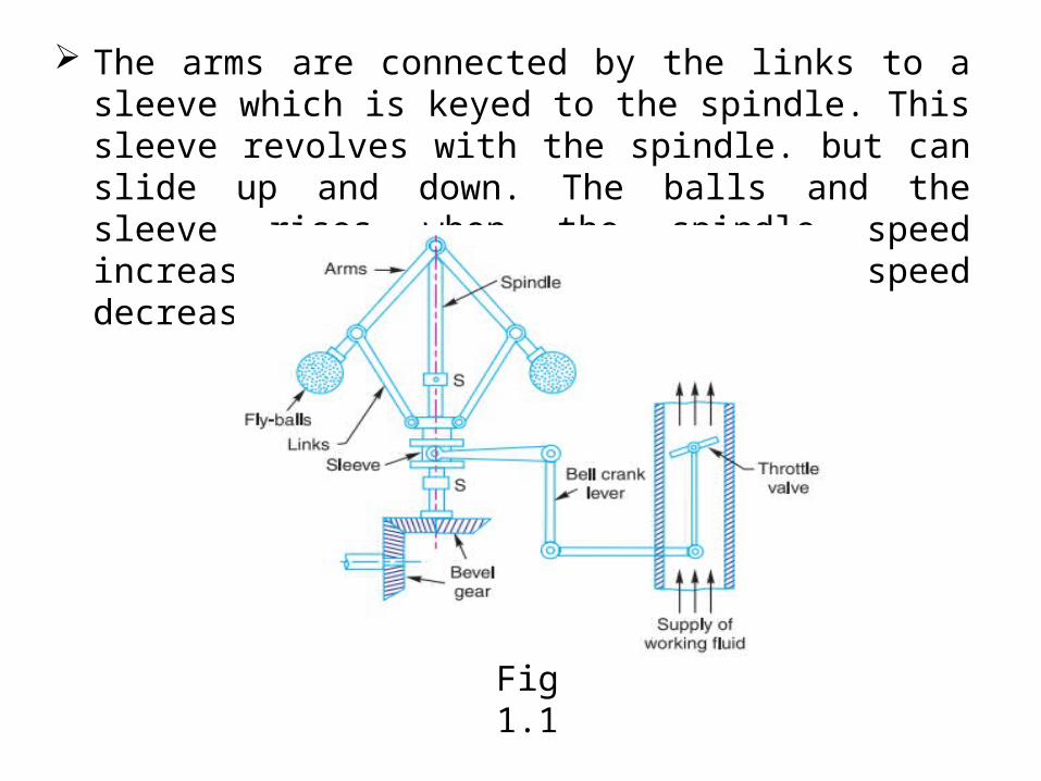
The arms are connected by the links to a sleeve which is keyed to the spindle. This sleeve revolves with the spindle. but can slide up and down. The balls and the sleeve rises when the spindle speed increases and falls when the speed decreases.
Fig 1.1

WATT GOVERNOR
The simplest form of a centrifugal governor is a watt governor, as shown in Fig. 1.2. It is basically a conical pendulum with links attached to a sleeve of negligible mass.
H=895/ N2
where H is the height of the governor
N is the speed of the balls
Fig 1.2
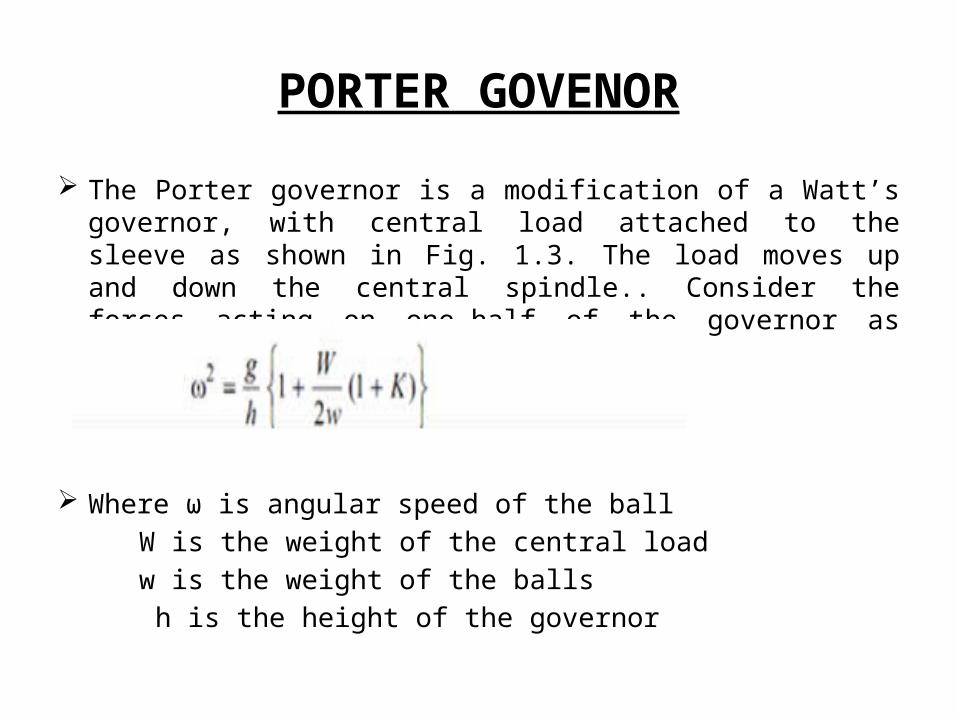
PORTER GOVENOR
The Porter governor is a modification of a Watt’s governor, with central load attached to the sleeve as shown in Fig. 1.3. The load moves up and down the central spindle.. Consider the forces acting on one-half of the governor as shown in Fig. 1.3
Where ω is angular speed of the ball
W is the weight of the central load
w is the weight of the balls
h is the height of the governor
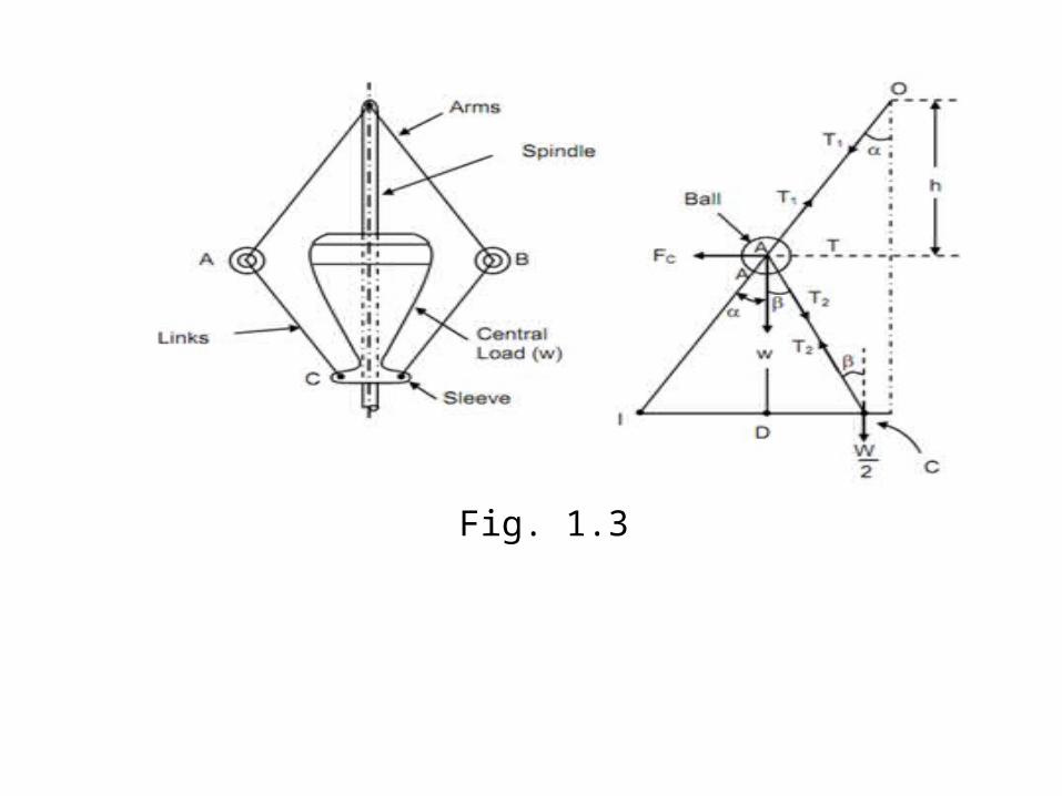
Fig. 1.3
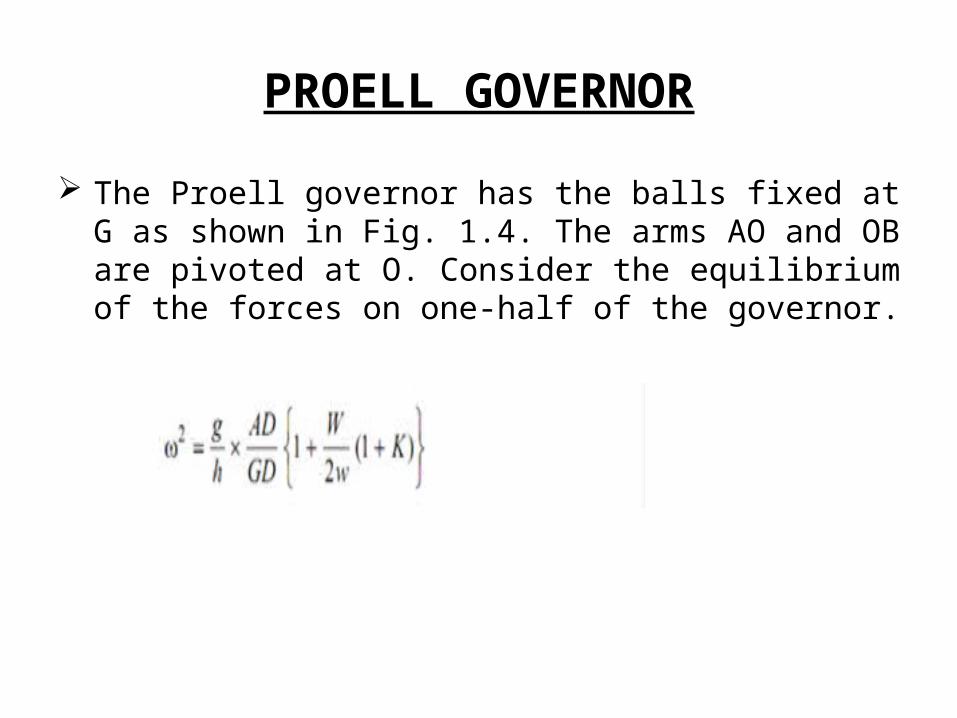
PROELL GOVERNOR
The Proell governor has the balls fixed at G as shown in Fig. 1.4. The arms AO and OB are pivoted at O. Consider the equilibrium of the forces on one-half of the governor.
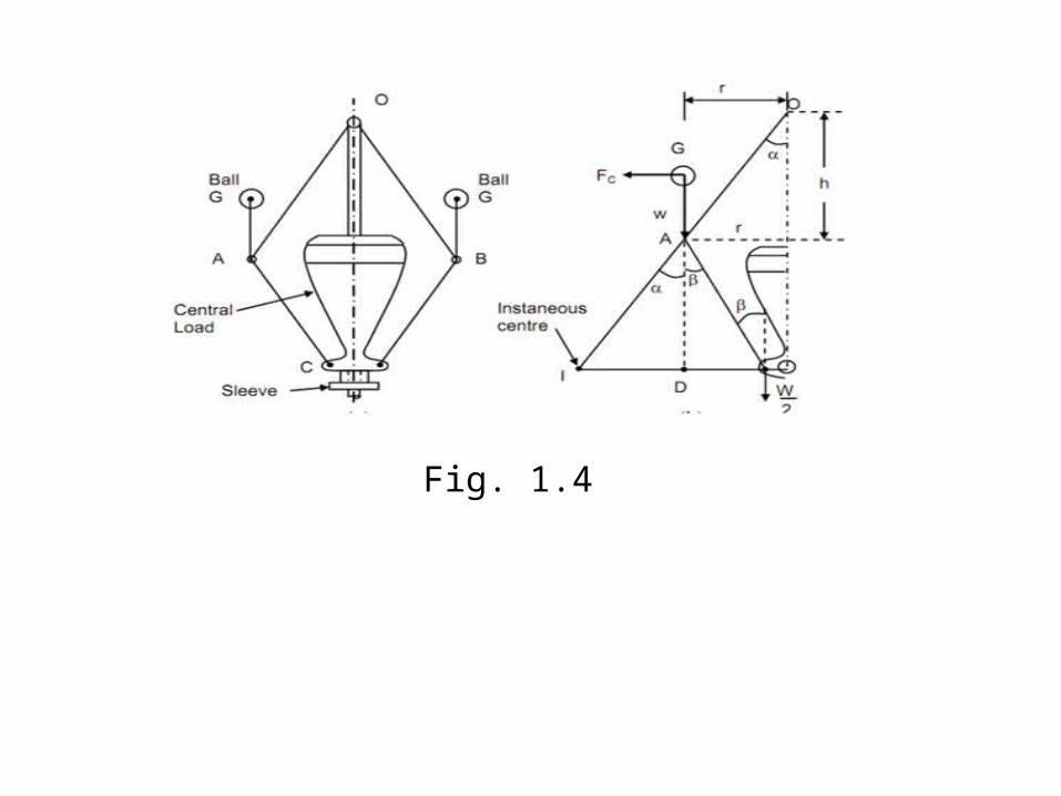
Fig. 1.4
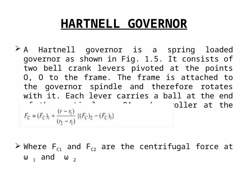
HARTNELL GOVERNOR
A Hartnell governor is a spring loaded governor as shown in Fig. 1.5. It consists of two bell crank levers pivoted at the points O, O to the frame. The frame is attached to the governor spindle and therefore rotates with it. Each lever carries a ball at the end of the vertical arm OA and a roller at the end of the horizontal arm OC.
Where FC1 and FC2 are the centrifugal force at ω 1 and ω 2
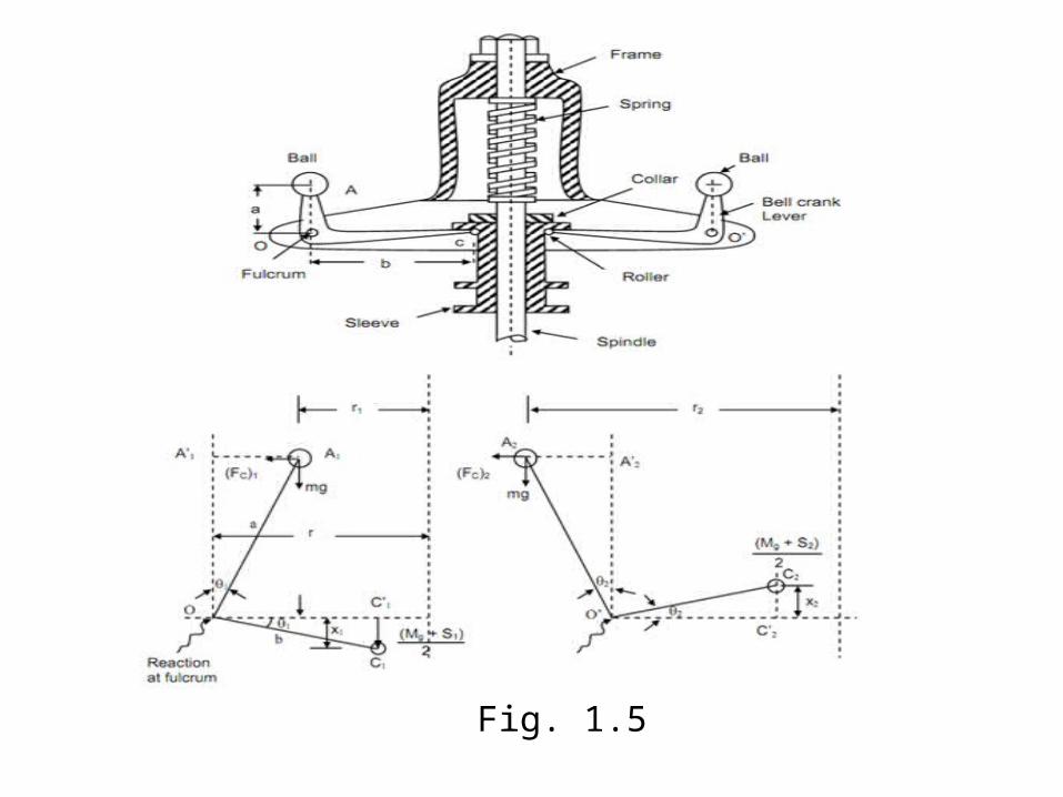
Fig. 1.5
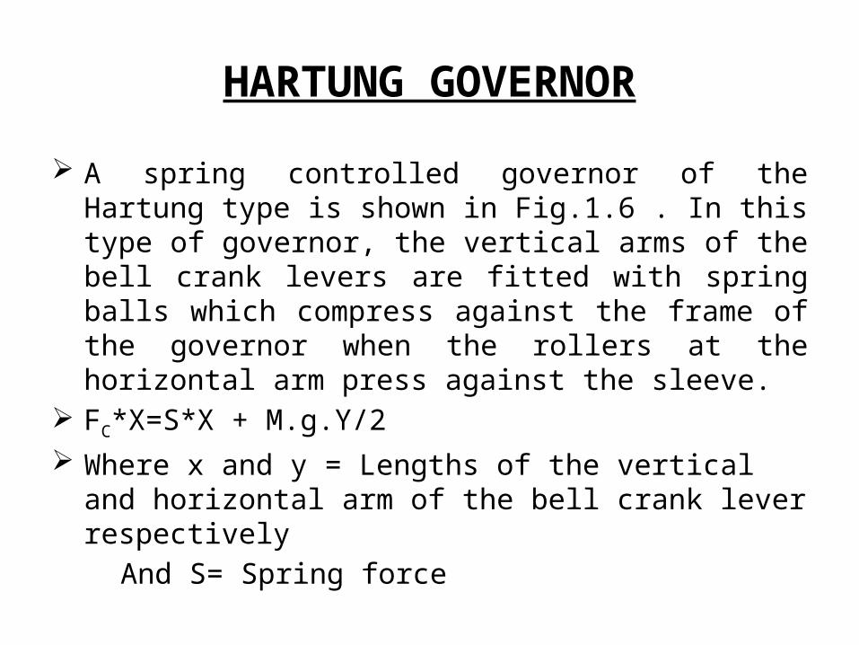
HARTUNG GOVERNOR
A spring controlled governor of the Hartung type is shown in Fig.1.6 . In this type of governor, the vertical arms of the bell crank levers are fitted with spring balls which compress against the frame of the governor when the rollers at the horizontal arm press against the sleeve.
FC*X=S*X + M.g.Y/2
Where x and y = Lengths of the vertical and horizontal arm of the bell crank lever respectively
And S= Spring force
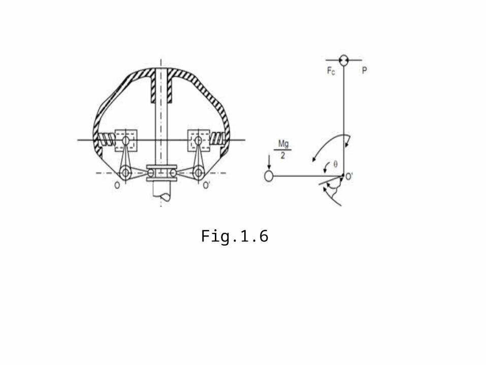
Fig.1.6

WILSON-HARTNELL GOVERNOR
A Wilson-Hartnell governor is a governor in which the balls are connected by a spring in tension. An auxiliary spring is attached to the sleeve mechanism through a lever by means of which the equilibrium speed for a given radius may be adjusted. The main spring may be considered of two equal parts each belonging to both the balls. The line diagram of a Wilson-Hartnell governor is shown in Fig 1.7
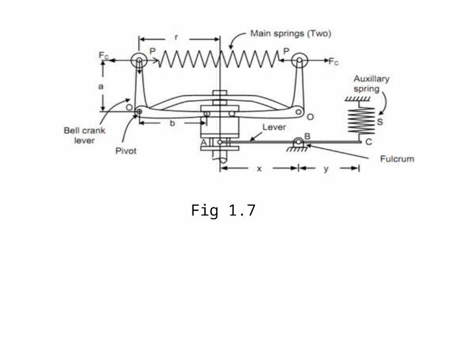
Fig 1.7

SENSITIVENESS OF GOVERNOR
The sensitiveness is defined as the ratio of the difference between the maximum and minimum equilibrium speeds to
the mean equilibrium speed. N1 = Minimum equilibrium speed,
N2 = Maximum equilibrium speed, and
N = Mean equilibrium speed =(N1+N2 )/2
Sensitiveness of the governor=(N2-N1)/N
STABILITY OF GOVERNOR
A governor is said to be stable when for every speed within the working range there is a definite configuration i.e. there is only one radius of rotation of the governor balls at which the governor is in equilibrium. For a stable governor, if the equilibrium speed increases, the radius of governor balls must also increase.
EFFORT AND POWER OF GOVERNOR
The effort of a governor is the mean force exerted at the sleeve for a given percentage change of speed. It may be noted that when the governor is running steadily, there is no force at the sleeve. But, when the speed changes, there is a resistance at the sleeve which opposes its motion. It is assumed that this resistance which is equal to the effort, varies uniformly from a maximum value to zero while the governor moves into its new position of equilibrium.
The power of a governor is the work done at the sleeve for a given percentage change of speed. It is the product of the mean value of the effort and the distance through which the sleeve moves.
Mathematically, Power = Mean effort × lift of sleeve
