government of india ministry of railways on... · widely used on indian railways for detecting...
TRANSCRIPT

GOVERNMENT OF INDIA
MINISTRY OF RAILWAYS
Centre
for
Advanced
Maintenance
TECHnology
Maharajpur, Gwalior - 474 020 (INDIA)
: 0751 - 2470869 & Fax : 0751 - 2470841
BBOOOOKKLLEETT OONN
UULLTTRRAASSOONNIICC TTEESSTTIINNGG
OOFF RRAAIILL (Need Based Concept)
CAMTECH/C/2005/USFD/1.0
August - 2005
EXECELLENCE IN MAINTENANCE
(For Official Use Only)

UULLTTRRAASSOONNIICC TTEESSTTIINNGG
OOFF
RRAAIILL
(Need Based Concept)

Foreword
Ultrasonic flaw detection (USFD) technique is
widely used on Indian Railways for detecting flaws in
rails for safety consideration of the track. This booklet
gives correct knowledge for detecting flaws in the rail.
This booklet mainly focuses on procedure,
calibration of machine, flaw marking and action to be
taken during USFD testing of rail (need-based concept),
for ensuring reliable testing and optimum output of
machines.
Civil Engineering branch of CAMTECH has
made excellent effort to bring out this booklet. I am sure
that this booklet would be useful as reference book for
USFD machine officials & field staff of engineering
branch.
CAMTECH/Gwalior R.N.Misra
Date : 01 .08.2005 Executive Director

Preface
Detection of flaws in rails and their timely
replacement is an ongoing process. Timely detection &
replacement of flaws is required to avoid fracture in track,
which at times can have dangerous consequences.
The objective of this booklet is to provide basic
information and technical details regarding USFD testing of
rail (Need based concept) for the USFD testing staff and
inspecting official. It covers frequency of testing, calibration
and sensitivity setting of machine, interpretation of oscillogram
pattern, and marking of flaws with action to be taken.
This booklet is not statutory & contents are for the
purpose of guidance only. It also does not supersede any
existing instructions from Railway Board, RDSO, Zonal
Railways and provisions of IRPWM, USFD manual (CS upto
15) on the subject.
I am grateful for the assistance given by Shri Neeraj
Shrivastava, STA/Civil/CAMTECH, who went through the
complete text, collected information, data etc. Nice data entry
has done by Shri Ramesh Bhojwani, Console Operator,
CAMTECH.
We welcome valuable suggestions from our readers
for further improvements.
CAMTECH/Gwalior Manoj K. Agarwal
Date : 01.08.2005 Director/Civil

CONTENTS
Sr. No. Description/Topic Page Nos.
Foreword i
Preface ii
Content iii
Correction Slip iv
1.0 General 01
2.0 Equipment 02
3.0 Probes 03
4.0 Periodicity of rail testing 04
5.0 Classification of flaws 06
6.0 Competency of testing 07
7.0 Procedure of ultrasonic testing
of rails
07
8.0 Action to be taken 17
Notes 18
***

ISSUE OF CORRECTION SLIPS
The correction slips to be issued in future for
this handbook will be numbered as follows:
CAMTECH/2005/C/USFD/1.0/CS. # XX
date ……
Where “XX” is the serial number of the
concerned correction slip (starting from 01 onwards).
CORRECTION SLIPS ISSUED
Sr. No.
of
C.Slip
Date
of
issue
Page no. and
Item No.
modified
Remarks

CAMTECH/C/2005/USFD/1.0
Booklet on Ultrasonic Testing of Rail August - 2005
1
Go to index
Ultrasonic Testing of Rail (Need based concept)
1.0 General
Rails are periodically inspected for detecting flaws and
their timely replacement to avoid fracture in track, which
at times can have dangerous consequences. Detection of
flaws is carried out either by visual examination of rails
or by ultrasonic flaw detection (USFD) technique.
In USFD, flaws are detected by using ultrasonic waves
i.e. sound waves of 2-4 MHz. These waves are
generated, transmitted to the rail and received back from
the rail by small piece of electric crystal fitted in the
probe which moves over the rail. Reflection received
back is displayed on the oscilloscope screen.
Ultrasonic waves transmitted from the probe get
reflected backward whenever they encounter any change
in medium. On flawless rail, the waves are reflected
from the rail table and later from the rail bottom. On the
oscilloscope screen these reflections appears in the form
of two peaks at the distance corresponding to rail height.
On defective rail, the waves are reflected from the rail
table and then from the flaw surface seldom reaching rail

CAMTECH/C/2005/USFD/1.0
Booklet on Ultrasonic Testing of Rail August - 2005
2
bottom. In this case second peak is nearer and the
distance indicates the depth of flaw.
With correct calibration and correct interpretation of
oscilloscope pattern, it is possible to detect type of flaw,
its magnitude and location.
2.0 Equipment
For USFD testing, RDSO approved, portable machine
based on scan pulse-echo technique with ultrasonic flaw
detectors are used. These machines are fully
transistorised and battery operated. Machines are of two
types viz. single rail tester (SRT) and double rail tester
(DRT).
Single rail tester (SRT)
Single rail tester is capable of testing only one of the rails
at a time and is provided with five probes i.e. 00, 70
0
Forward (F), 700 Backward (B), 37
0 Forward (F) and 37
0
Backward (B).
The signal received from the defects by any of the above
probes is indicated on the cathode ray tube (CRT) screen.
In order to find out the origin of detection i.e. which
probe has picked up the defect, process of eliminating
the individual probe operation is utilised.

CAMTECH/C/2005/USFD/1.0
Booklet on Ultrasonic Testing of Rail August - 2005
3
Double rail tester (DRT)
The double rail tester is capable of testing both the rails
at a time. However, for each rail, only three probes have
been provided i.e. 00, 70
0 Forward and 70
0 Backward.
This equipment, unlike the single rail tester, has multi-
channel facility i.e. the signal received from each probe
can be instantaneously distinguished without taking
recourse to process of elimination. This equipment has
also been provided with a threshold arrangement, LED
display and audio alarm in addition to the CRT screen.
Thus there are three modes of defect indication i.e., CRT,
audio alarm and LED display.
Total life of the USFD machines is eight-year.
3.0 Probes
For rail testing double crystal probes are used as
under :
Probe
Type
Freq. Crystal
/size
Remarks
00 Normal
probe
4 MHz 18 mm
circular/ 18
x 18 mm
square
For detecting
horizontal
defects in
head, web or
foot.

CAMTECH/C/2005/USFD/1.0
Booklet on Ultrasonic Testing of Rail August - 2005
4
70
0 Probe 2 MHz 20 mm
circular/ 20
x 20 mm
square
For detecting
transverse
defects in
head.
370 Probes 2 MHz 20 mm
circular/ 20
x 20 mm
square
For detecting
defects
originating
from the bolt
hole (star
crack). (with
SRT only)
For detection of bolthole defects, the DRT works on the
principle of back wall drop, which in the event of a
bolthole crack shows reduction in echo-amplitude of the
back wall.
4.0 Periodicity of rail testing
There are two systems of USFD testing based on
inspection frequency and permissible defect size viz.
conventional and need based system. In need based
system, frequency of rail testing is as under :
Initial testing
Rails are tested at steel manufacturing plant with on line
ultrasonic testing equipment. In case initial testing of

CAMTECH/C/2005/USFD/1.0
Booklet on Ultrasonic Testing of Rail August - 2005
5
rails has not been done in the rail manufacturing plant,
the rail shall be tested either at flash butt welding plant or
at site. In no case rail should be laid in track without
USFD testing.
Subsequent testing
After the initial testing of rails, in rail manufacturing
plant the first retesting is carried out after the test free
period i.e. after passage of 15 % stipulated service life in
GMT or after passage of 25 % stipulated service life in
GMT for rails rolled in April 1999 and onward.
After retesting, subsequent testing on all BG routes is
carried out after passage of 8 GMT subject to maximum
interval of 1 year as under:
Route Annual GMT Testing frequency
BG Up to 8 12 months
>8≤12 9 months
>12≤16 6 months
>16≤24 4 months
>24≤40 3 months
>40 2 months
* For other sections, Chief Engineer may adopt a
frequency at his discretion.

CAMTECH/C/2005/USFD/1.0
Booklet on Ultrasonic Testing of Rail August - 2005
6
Whenever rails are not tested in rail manufacturing
plants, the test free period is not applicable and the rail
testing shall be done at the periodicity given above right
from the day of its laying in field.
5.0 Classification of flaws
Depending on the nature and extent of internal flaws and
the traffic density and speed on the section, the defects
are classified as under (As per Annexure VII of USFD
Manual -1998) :
I.M.R. (immediate removal): The flaw which is
serious in nature and can lead to sudden failure is
classified as I.M.R. Immediately after detection,
such portions shall be marked with red paint (three
cross) on the web of the rail on both faces.
O.B.S. (under observation): If the defect is such
that it is not expected to result in fracture till re-
scanning is done, it is classified as O.B.S. Such
defects shall be marked by red paint (one cross) on
both faces of the web.
IMRW/OBSW: These are the defects at weld
location detected during through rail testing
requiring similar action as rail.

CAMTECH/C/2005/USFD/1.0
Booklet on Ultrasonic Testing of Rail August - 2005
7
Go to index
6.0 Competency for testing
Inspector carrying out the ultrasonic testing of rail shall
be RDSO trained, in the techniques of USFD testing.
7.0 Procedure of ultrasonic testing of rails
The procedure for ultrasonic testing of rails is divided in
the following steps:
a. Visual inspection of equipment and accessories
b. Calibration of the equipment
c. Sensitivity (gain) setting of the equipment and
probes
d. Checking of the equipment and probes
e. Testing and interpretation
a. Visual inspection of equipment and accessories
(daily check)
Ultrasonic equipment is to be inspected daily before start
of work for proper functioning of plugs, holders, cables,
etc. In addition battery condition, proper functioning of
echo-control, proper control and smooth movement of
control wheel and alignment of the probe shall be
checked by the USFD operator before commencement of
the tests.

CAMTECH/C/2005/USFD/1.0
Booklet on Ultrasonic Testing of Rail August - 2005
8
b. Calibration of the equipment
The ultrasonic rail tester is to be calibrated for 300 mm
depth range (longitudinal wave) with the help of 60 X 50
X50 mm block of steel to grade 45C8 of IS : 1875-1992.
Procedure of calibration
Switch on normal probe
Adjust the on set of the surface echo from the
Perspex of normal probe to zero by using horizontal
shift control knob/delay knob, provided in the
electronic unit.
Place the calibration block below normal probe
using water as couplant.
Adjust the range by H-shift/Delay and range control
knob simultaneously so that following signals
appear on the screen.
The location of signals for 300 mm has been
indicated below.
On set of the surface echo from the perspex at 0
main scale div.
60 mm signal at 1 main scale Horizontal Division.
120 mm signal at 2 main scale Horizontal Division.
180 mm signal at 3 main scale Horizontal Division.
240 mm signal at 4 main scale Horizontal Division.
300 mm signal at 5 main scale Horizontal Division.

CAMTECH/C/2005/USFD/1.0
Booklet on Ultrasonic Testing of Rail August - 2005
9
The equipment is now calibrated for 60 mm of steel
per main scale horizontal div. for longitudinal wave.
c. Sensitivity (gain) setting of the equipment and
probes (weekly check)
The sensitivity of the USFD equipment shall be set up
once in a week with the help of standard rail pieces as
mentioned below:
(i) Place the testing trolley on the standard rail
piece having artificial flaws. Check the
alignment of probes to make sure that they
travel centrally in line with the axis of the rail
head and web.
(ii) Set the acoustic barrier of the normal probe at
right angle to the longitudinal direction of rail.
(iii) Adjust the gap of 0.2 mm approx. in between
the contact face of the normal probe and the
delay probe shoe. Check the gap by keeping the
straight edge of a 150 mm steel scale on the sole
using a feeler gauge or a stainless steel blade.
(iv) Adjust the gap of the angle probes as in (iii)
above.
(v) Open the water nozzle and regulate water flow
on the probes at an optimum speed.
(vi) The function of various probes is checked and
the sensitivity adjusted as under :

CAMTECH/C/2005/USFD/1.0
Booklet on Ultrasonic Testing of Rail August - 2005
10
Normal probe: The equipment shall be able to
detect 5 mm dia. hole at the web-foot junction of the
standard rail. The amplitude of the flaw echo shall
be adjusted to 60% of full screen height by the
adjustment of gain knob of USFD. (position of
potentiometer knobs in the junction box should be
set at 50% rotation)
Angle probe 700 (forward & backward): The
equipment shall be able to detect 12 mm dia. hole in
the head portion of the standard rail respectively by
both forward and backward probes. The amplitude
of the flaw shall be set to 60% of screen height.
When the probe is in the reflecting range, a pulse
appears on the screen which during travel source
higher amplitude. The equipment should be
progressively moved till maximum height of the
pulse is obtained. At this location the height of the
pulse shall be adjusted to 60% of full screen height
by adjusting individual potentiometer provided in
the junction box.
Once the sensitivity/gain setting has been done it
should not be disturbed during testing.

CAMTECH/C/2005/USFD/1.0
Booklet on Ultrasonic Testing of Rail August - 2005
11
d. Checking the equipment characteristics (monthly
check)
The characteristics of the equipment shall be
checked at least once in a month according to
IS:12666 - 88.
Following characteristics are checked -
Linearity of time base of flaw detector
Linearity of amplification of flaw defector
Penetrative power
Resolving power
Probe index
Beam angle
e. Testing and interpretation of Oscillogram
pattern
After sensitivity setting actual testing of rails is to be
carried out by moving the equipment over the rail and
the oscillogram pattern is interpreted for detecting flaws
and their classifications as under :

CAMTECH/C/2005/USFD/1.0
Booklet on Ultrasonic Testing of Rail August - 2005
12
Go to index
(a) Rail defects
By Normal probe
Nature of defect Oscillogram
pattern
Classifi
-cation
1. Within fishplated
area
(i) Any defect
connected with rail end
in any location (head,
web, foot junctions) of
the rails end covering
both the bolt hole length
or covering first bolt
hole.
(ii) Any defect
connecting both bolt
holes.
(iii) Any defect
originating from bolt
holes and extended up
the head web junctions
or web/foot junctions.
For (i) & (ii)
No back echo,
Flaw echo with/
without multiples
Or
Drop in back echo
with flaw echo
with/ without
multiple
For (iii)
No back echo
with/ without flaw
echo
IMR
IMR
CAMTECH/C/2005/USFD/1.0
Booklet on Ultrasonic Testing of Rail August - 2005
13
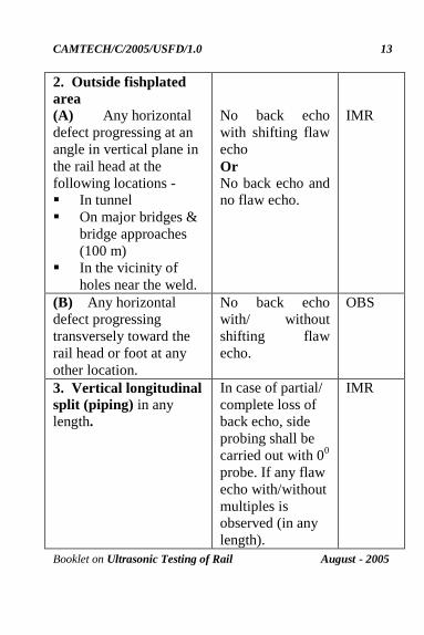
2. Outside fishplated
area (A) Any horizontal
defect progressing at an
angle in vertical plane in
the rail head at the
following locations -
In tunnel
On major bridges &
bridge approaches
(100 m)
In the vicinity of
holes near the weld.
No back echo
with shifting flaw
echo
Or
No back echo and
no flaw echo.
IMR
(B) Any horizontal
defect progressing
transversely toward the
rail head or foot at any
other location.
No back echo
with/ without
shifting flaw
echo.
OBS
3. Vertical longitudinal
split (piping) in any
length.
In case of partial/
complete loss of
back echo, side
probing shall be
carried out with 00
probe. If any flaw
echo with/without
multiples is
observed (in any
length).
IMR

CAMTECH/C/2005/USFD/1.0
Booklet on Ultrasonic Testing of Rail August - 2005
14
By 700 Probe
Any transverse defect in
the rail head.
Flaw echo of 50%
horizontal scale
movement and
60% of full scale
height or more.
IMR
Any transverse defect in
the rail head at the
following locations-
In tunnel
On major bridges &
bridge approaches
(100 m).
In the vicinity of
holes near the weld.
Flaw echo of 30%
horizontal scale
movement and
20% of full scale
height or more.
IMR
Any transverse defect in
the rail head at any other
location.
Flaw echo of 30%
to 50% horizontal
scale movement
and 20% to 60% of
full-scale height.
OBS

CAMTECH/C/2005/USFD/1.0
Booklet on Ultrasonic Testing of Rail August - 2005
15
(b) Defects at weld location (AT+FBW)
By Normal probe
Nature of defect Oscillogram
pattern
Classifi
- cation
A) Any horizontal defect
progressing at an angle
in vertical plane in the
rail head at the following
locations-
In tunnel
On major bridges &
bridge approaches
(100m)
No back echo
with Shifting
flaw echo.
IMRW
B) Any horizontal defect
progressing transversely
in the rail head at any
other location
No back echo
with Shifting
flaw echo.
OBSW

CAMTECH/C/2005/USFD/1.0
Booklet on Ultrasonic Testing of Rail August - 2005
16
Go to index
By 700 probe
Any transverse defect in
the rail head
Flaw echo of
50% horizontal
scale movement
and 60% of full-
scale height or
more.
IMRW
Any transverse defect in
the rail head at the
following locations -
In tunnel
On major bridges &
bridge approaches
(100m).
Flaw echo of
30% horizontal
scale movement
and 20% of full-
scale height or
more.
IMRW
Any transverse defect in
the rail head at any other
location.
Flaw echo of
30% to 50%
horizontal scale
movement and
20% to 60% of
full-scale height
or more.
OBSW

CAMTECH/C/2005/USFD/1.0
Booklet on Ultrasonic Testing of Rail August - 2005
17
8.0 Action to be taken
Classif
ication
Painting
on both
faces of
web
Action to be
taken
Interim Action
IMR/
IMRW
Three
cross with red paint
Replacement by
a sound tested rail piece of not
less than 6 m.
within 3 days of detection.
PWI / USFD shall
impose speed restriction of 30 kmph
immediately. He should
communicate to section PWI about the flaw
location who shall
ensure that clamped joggled fishplate is
provided within 24
hours.
OBS/ OBSW
One cross with red
paint.
Rail/weld to be provided with
clamped joggled
fishplate within three days.
PWI/USFD to specially record
the observations
of the locations in his register in
subsequent
rounds of testing.
PWI/USFD to advise sectional PWI within 24
hours about the flaw
location. Keyman to watch
during daily patrolling till it is joggled fish-
plated.
***

CAMTECH/C/2005/USFD/1.0
Booklet on Ultrasonic Testing of Rail August - 2005
18
Go to index
NOTES
1.
2.
3.
4.
5.
6.
7.
8.
9.
10.
11.
12.
13.
14.
15.

CAMTECH/C/2005/USFD/1.0
Booklet on Ultrasonic Testing of Rail August - 2005
19
OUR OBJECTIVE
The contents of this booklet are for guidance only
& are not statutory. It also does not supersede any
existing instructions from Railway Board, RDSO
and zonal Railways & the provisions of IRPWM,
USFD Manual on the subject.
Contact person : Director (Civil)
Postal Address : Centre for Advanced
Maintenance Technology,
Maharajpur, Gwalior (M.P.)
Pin code – 474 020
Phone : (0751) - 2470869, 2470803
Fax : (0751) - 2470841
To upgrade Maintenance
Technologies and Methodologies and
achieve improvement in productivity and
performance of all Railway assets and
manpower which inter-alia would cover
Reliability, Availability, and Utilisation. ________________________________