government of india - directorate general of civil · pdf file1.18.1.1 standard operating...
TRANSCRIPT

GOVERNMENT OF INDIA
REPORT ON ACCIDENT TO M/s PAWAN HANS DAUPHIN N3 HELICOPTER
VT-PWF AT BOMBAY HIGH
ON 04/11/2015
AIRCRAFT ACCIDENT INVESTIGATION BUREAU MINISTRY OF CIVIL AVIATION
NEW DELHI

Foreword
This document has been prepared based on the evidences collected during the investigation, discussions held with the post holders and involved personnel, replay of recorders and opinion from the experts. The investigation has been carried out in accordance with Annex 13 to the convention on International Civil Aviation and under Rule 11 of the Aircraft (Investigation of Accidents and Incidents) Rules 2012 of India This investigation is conducted not to apportion blame or to assess individual or collective responsibility. The sole objective is to draw lessons from this accident which may help to prevent such accidents in future.
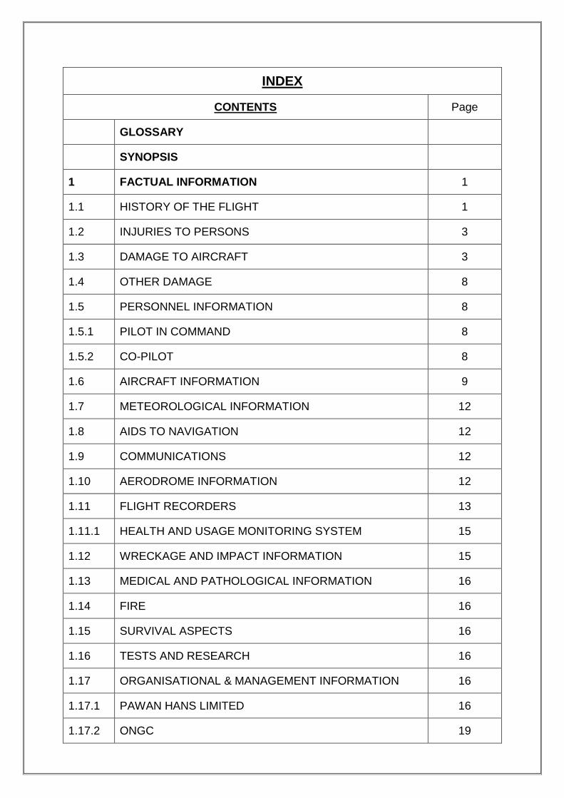
INDEX
CONTENTS Page
GLOSSARY
SYNOPSIS
1 FACTUAL INFORMATION 1
1.1 HISTORY OF THE FLIGHT 1
1.2 INJURIES TO PERSONS 3
1.3 DAMAGE TO AIRCRAFT 3
1.4 OTHER DAMAGE 8
1.5 PERSONNEL INFORMATION 8
1.5.1 PILOT IN COMMAND 8
1.5.2 CO-PILOT 8
1.6 AIRCRAFT INFORMATION 9
1.7 METEOROLOGICAL INFORMATION 12
1.8 AIDS TO NAVIGATION 12
1.9 COMMUNICATIONS 12
1.10 AERODROME INFORMATION 12
1.11 FLIGHT RECORDERS 13
1.11.1 HEALTH AND USAGE MONITORING SYSTEM 15
1.12 WRECKAGE AND IMPACT INFORMATION 15
1.13 MEDICAL AND PATHOLOGICAL INFORMATION 16
1.14 FIRE 16
1.15 SURVIVAL ASPECTS 16
1.16 TESTS AND RESEARCH 16
1.17 ORGANISATIONAL & MANAGEMENT INFORMATION 16
1.17.1 PAWAN HANS LIMITED 16
1.17.2 ONGC 19

1.17.2.1 ONGC RADIO OFFICER (MARINE) 21
1.18 ADDITIONAL INFORMATION 21
1.18.1 OFFSHORE OPERATING ENVIRONMENT 21
1.18.1.1 STANDARD OPERATING PROCEDURES 22
1.18.1.2 HELIDECK SAFETY -WORLDWIDE 24
1.18.2 HELICOPTER NIGHT VFR OPERATIONS 24
1.18.3 DGCA CAR ON SUBJECT 25
1.18.4 HELICOPTER ROUTING MUMBAI/JUHU 26
1.18.5 AIS(AUTOMATIC IDENTIFICATION SYSTEM) - TRACKING
28
1.18.6 SPATIAL DISORIENTATION 29
1.18.7 BLACK HOLE ILLUSION 30
1.18.8 SALIENT OBSERVATION FROM WRECKAGE EXAMINATION
31
1.18.9 HUMAN FACTOR AND CRM 55
1.19 USEFUL AND EFFECTIVE TECHNIQUES 56
2 ANALYSIS
2.1 HELICOPTER AND ITS MAINTENANCE 57
2.2 CREW QUALIFICATION 57
2.3 TRAINING 58
2.4 HELIDECK SAFETY 59
2.5 WEATHER 60
2.6 WRECKAGE EXAMINATION 61
2.7 FLIGHT RECORDER AND SPECTRUM ANALYSIS 62
2.7.1 CVR 62
2.7.2 SPECTRAL ANALYSIS 63
2.7.3 FDR 64

2.8 CRM 66
2.9 SAFETY MANAGEMENT SYSTEM (PHL AND ONGC) 66
2.10 CIRCUMSTANCES LEADING TO THE ACCIDENT 67
3 CONCLUSIONS
3.1 FINDINGS 69
3.1.1 GENERAL 69
3.1.2 ORGANISATIONAL INFLUENCES 70
3.1.3 UNSAFE SUPERVISION 71
3.1.4 PRECONDITIONS FOR UNSAFE ACTS 72
3.1.5 ACCIDENT SEQUENCE 72
3.2 PROBABLE CAUSE OF THE ACCIDENT 72
4 SAFETY RECOMMENDATIONS 74

GLOSSARY
AIP Aeronautical Information Publication
AME Aircraft Maintenance Engineer
AMM Aircraft Maintenance Manual
ATC Air Traffic Control
BEA Bureau ďenquêtes et ďAnalysis
CAP Civil Aviation Publication
CAR Civil Aviation Requirement
CPL Commercial Pilot License
CVR Cockpit Voice Recorder
DGCA Directorate General of Civil Aviation
EASA European Aviation Safety Agency
ELT Emergency Locator Transmitter
FDR Flight Data Recorder
FIR Flight Information Region
GPS Global Positioning System
HUMS Health and Usage Monitoring System
IFR Instrument Flying Rules
ISO International Organisation for Standardisation
MGB Main Gear Box
NDB Non Directional Beacon
NTSB National Transport Safety Board
NSOP Non-Schedule Operator Permit
ONGC Oil and Natural Gas Corporation
PIC Pilot In Command
QNH Query: Nautical Height
QHSE Quality Health Safety and Environment
OHSAS Occupational Health and Safety Assessment Series
ROC Rate of Climb
ROD Rate of Descent
SOP Standard Operating Procedures
TRE Type Rated Examiner
TRI Type Rated Instructor

UTC Co-ordinated Universal Time
VFR Visual Flight Rules
VHF Very High Frequency
VOR VHF Omnidirectional Range

Synopsis
Pawan Hans Limited Dauphin AS 365 N3 helicopter VT-PWF was
involved in an accident while operating a night training flight on 4th November
2015 from WIS platform to a rig (RonTappmeyer). The pilot flying was a CHPL
holder occupying the right hand seat and undergoing night off-shore training
with an instructor PIC occupying the left hand seat. There were no
passengers on board.
The helicopter departed from Juhu at 1703 IST with 05 persons and
700 kgs of fuel on board and was to be designated as standby for Casualty
Evacuation (Night Ambulance). It was supposed to be parked in Bombay high
(WIS platform) for the night.
The flight from Juhu to WIS platform was uneventful and the helicopter
landed at 1804 IST. No snag was reported by the flight crew to the
engineering person (AME). As planned the crew after landing discussed
among themselves and decided for the training flight (night training) at 1900
hrs IST.
The helicopter took off from WIS helipad at 1910 hrs.The helicopter
was planned to land first at Ron Tappmeyer Rig attached to EE platform in
South Field and then to floating platform Sewak. The helicopter made an
approach to land on Ron Tappmeyer but as the helicopter was high on
approach, it made a go around and banked to the left. Simultaneously it
descended and few seconds later the helicopter crashed into the sea and was
destroyed. Both the flight crew members received fatal injuries.
Government of India vide notification no AV-15029/115/2015-DG
ordered investigation of the subject accident by a Committee of Inquiry. (The
intimation of the accident was provided to ICAO, TSB Canada, BEA France
and NTSB USA as per the requirements of ICAO Annexure 13).
1
1.0 FACTUAL INFORMATION
1.1 History of Flight
Pawan Hans Limited Dauphin AS 365 N3 helicopter VT-PWF was
involved in an accident while operating a night training flight on 4th November
2015 from WIS platform to a rig (Ron Tappmeyer). The pilot flying was a
CHPL holder occupying the right hand seat and undergoing night off-shore
training with an instructor PIC occupying the left hand seat. There were no
passengers on board. The helicopter crashed into sea and was destroyed.
Both the flight crew members received fatal injuries.
On 3rd November 2015, the involved flight crew was informed about
roster of the flight which was as per the published flight schedule. The flight
crew prior to operating the flight from Juhu had undergone Pre-Flight Medical
Examination (PFME) including the breath analyser test at the PHL facilities.
The weather at Juhu at the time of departure was, visibility 3 km in haze and
at offshore location visibility of 5000 m, temperature 29 degree centigrade,
wind direction 250°, wind speed 28 knots & QNH as 1005.
The flight plan from Juhu was filed to fly the route under VFR
conditions at 3000 feet AGL with endurance of 02.15 hours. The helicopter
departed from Juhu at 1703 IST with 05 persons and 700 kgs of fuel on
board. The helicopter was flown from Juhu helipad (ONGC base) to the
offshore WIS platform SLQ and the helicopter was designated as standby for
Casualty Evacuation (Night Ambulance). It was parked in Bombay high (WIS
platform) for the night.
The route followed by the helicopter was VAJJ – SCA – ICD – WIS.
The flight from Juhu to WIS platform was uneventful and the helicopter landed
at 1804 IST. No snag was reported by the flight crew to the engineering
person (AME).
PHL had requested ONGC for permission regarding carrying out night
training flight (recency) of one of the crew members on the night of 4th of

2
November 2015. The crew after landing discussed among themselves and
decided for the training flight at 1900 hrs IST.
Refueling was carried out after landing at WIS platform and total fuel
on board prior to the training flight was 790 kgs as per the gauge. Fuel sample
was also taken and checked. There was no abnormality. Both the flight crew
members after carrying out check and obtaining clearance from the SLQ radio
officer started the engines. The clearance to start the engines was also given
by the AME. However as per the AME he was not having any flight plan/
schedule of the night flying to be carried out. The AME was verbally informed
by the flight crew that they will be landing back at WIS within 30-45 minutes.
No flight acceptance certificate is given/ taken or retained at platforms or
offshore.
Radio Officer (ONGC), SLQ platform on duty was aware that medevac
helicopter will do night flying and practice landings. Accordingly he had
informed vessel Samudra-Sevak (location east of SCA) and rig Ron
Tappmeyer (location EE platform) that the helicopter will carry out night
practice landings. Samudra Sevak was in open location and without any
obstructions for landing. The flight crew was also informed about readiness of
SEVAK and Ron Tappmeyer.
The helicopter took off from WIS helipad at 1910 hrs. At the time of
take-off, the weather information (winds) communicated to the flight crew was
015°/10 knots. The information was copied by the flight crew.
The helicopter was planned to land first at Ron Tappmeyer Rig
attached to EE platform in South Field and then to Sewak. While clearing the
helicopter to land at Ron Tappmeyer, winds communicated to the flight crew
were 10 to 12 knots with a direction of 020°.
The helicopter made an approach to land on Ron Tappmeyer but as
the helicopter was high on approach, it made a go around and banked to the
left. Simultaneously it descended and few seconds later the helicopter
crashed into the sea.

3
Search and Rescue operation was launched under the control of Coast
Guard. The debris of the helicopter was located on 09th of November 2015.
While body of trainee flight crew was found strapped up with the Captain seat
when the helicopter was winched out of the Sea, body of the instructor was
missing and is yet to be located. His seat belt was found to be in locked
position and the shoulder straps were free.
Government of India vide notification no AV-15029/115/2015-DG
ordered investigation of the subject accident by a Committee of Inquiry. (The
intimation of the accident was provided to ICAO, TSB Canada, BEA France
and NTSB USA by AAIB India as per the requirements of ICAO Annexure 13).
1.2 Injuries to Persons
INJURIES CREW PASSENGERS OTHERS
FATAL 2 Nil Nil
SERIOUS Nil Nil Nil
MINOR/ NONE Nil Nil
1.3 Damage to Helicopter
The helicopter was totally destroyed as a result of the impact with the
water. The wreckage was self contained & the main parts/ components were
recovered in one go from deep sea on 9th November 2015.
The retrieved wreckage contained front lower structure including the
instrument panel and the centre console; Main Rotor Hub (MRH) and Main
Gear Box (MGB) installed on the transmission deck; the engines; aft structure
including tail boom assembly; and tail rotor with fenestron. The wreckage after
retrieval was transported to Juhu by road. It was laid down at the PHL facility
for analysis of damages in detail. The wreckage was examined at Juhu and a
team of experts through BEA France who has appointed an accredited
representative to associate with the investigation as per ICAO Annex 13 was

4
requested to associate in the wreckage examination from the investigation
point of view. Committee along with BEA carried out examination of the
wreckage. Experts from the Manufacturer were also associated to pin point
the pattern of breakage of the structure and analyse tell tale signs if any from
the wreckage.
BEA had submitted a wreckage examination report which has been
used in this report and extracts have been incorporated. Observations
received from BEA on main rotor drive system, main rotor including blades,
tail rotor drive system, tail rotor, tail rotor controls, flight control, engines
including magnetic plugs, filters and BSI etc. are detailed in additional
information.
MAIN ROTOR BLADES
Observations from wreckage at Juhu
In the area of the front lower structure, the components like Radome
and lower panels are destroyed. Nose landing gear, co-pilot‘s door and

5
passenger‘s doors are disconnected. The maximum damage occurred on the
left side indicating impact from outside. The structure behind the centre
console is totally destroyed with floor totally broken and deformed.
1. DAMAGED RADOME
2. INSTRUMENT PANEL
(REAR)
3. DAMAGED PILOT DOOR
The instrument panel had shifted backwards during impact though
complete console is in position. The co-pilot‘s door is totally destroyed and the
damage matches with that on the left side of the structure. The front right
passenger‘s door is though available in full with some deformations but its
window is missing. Both the rear passenger‘s doors are available with left
passenger‘s door broken in its lower part.
1 2
3

6
When the wreckage was recovered from the sea, the main rotor was
connected to the main gear box. All the four blade root ends were connected
though only portion of blades were available. Three blades (red, blue and
yellow blades) had almost similar length available and the fourth blade (black
blade) portion available was of shorter length. The main gear box was
attached to the transmission deck with all the linkages in place.
The rear area of the aft structure and the tail boom is complete though
has deformations whereas the lower part of front area of the aft structure is
totally destroyed and deformed. The upper fairings are complete with little
deformation. The tail rotor drive shaft is connected to the aft structure by its
bearing supports. The shaft is complete though with a little bending
deformation. The front part of the tail rotor control shaft is not in position on
the tail boom. The flight recorder is in position in the tail boom. The area of the
tail boom located in front of the recorder was cut for removing the flight data
recorder.
The ―left side of the horizontal stabilizer and left outboard fin‖ assembly
is broken. On the right side, the lower outboard fin is broken. The right
horizontal stabilizer and the rest of the outboard fin are in position without
deformation. The rear part of the fenestron housing is broken. The rest of the
fenestron is complete with the blades in position without visible deformation.
The rear part of the tail rotor control shaft is connected at its rear end.

7
The right horizontal stabilizer in Position
The left horizontal stabilizer was broken
The two engines were near the main gear box (on retrieval of wreckage
from sea).
ENGINES
8
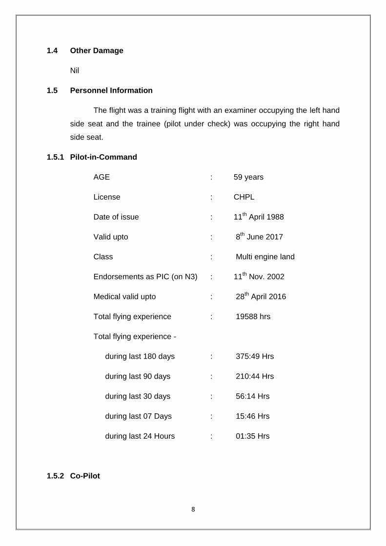
1.4 Other Damage
Nil
1.5 Personnel Information
The flight was a training flight with an examiner occupying the left hand
side seat and the trainee (pilot under check) was occupying the right hand
side seat.
1.5.1 Pilot-in-Command
AGE : 59 years
License : CHPL
Date of issue : 11th April 1988
Valid upto : 8th June 2017
Class : Multi engine land
Endorsements as PIC (on N3) : 11th Nov. 2002
Medical valid upto : 28th April 2016
Total flying experience : 19588 hrs
Total flying experience -
during last 180 days : 375:49 Hrs
during last 90 days : 210:44 Hrs
during last 30 days : 56:14 Hrs
during last 07 Days : 15:46 Hrs
during last 24 Hours : 01:35 Hrs
1.5.2 Co-Pilot

9
AGE : 59 years
License : CHPL
Date of Issue : 10th May 2012
Valid upto : 9th May 2017
Class : Multi engine land
Endorsements as PIC : 25th June 2012
Date of Med. Exam : 20th August 2015
Med. Exam valid upto : 19th February 2016
Total flying experience : 6700 hrs
Experience on type : 4115:25 hrs
Experience as PIC on type : 862 hrs
Total flying experience -
during last 180 days : 251:50 Hrs.
during last 90 days : 155:55 Hrs.
during last 30 days : 67:47 Hrs.
during last 07 Days : 14:15 Hrs.
during last 24 Hours : 1:35 Hrs.
1.6 Aircraft Information
The helicopter was operated under Non scheduled operator‘s Permit
No. 02/1998 which is valid up to 15th March 2017. Dauphin N3 helicopter is a
twin engine helicopter and the involved helicopter bearing serial number 6946
was manufactured by Euro copter in the year 2011. It is ONGC AS4 compliant
helicopter and has flown about 3255 hrs (approx) since new. The helicopter
was fitted with all the equipment required for IFR and offshore flying as per
DGCA requirements e.g. CVR/FDR, ELT, autopilot, weather radar, automatic

10
flotation gear inflation mechanism etc. It was also fully equipped for night
ambulance task.
The helicopter has undergone 5T (3000 hours/ 06 years) inspection at
Mumbai on 14-09-2015 at 3057.50 airframe hours. Subsequent to 5T
inspection there was no major defect reported on the helicopter. Subsequently
all lower inspections, after last flight inspection and pre-flight checks were
carried out as and when due before the accident. It is approved in the
―Normal‖ category under Sub-division ―Passenger Aircraft‖ and there is no
restriction of service life.
Certificate of Registration No. 4310, under Category ―A‖ was issued on
26.03.2012. The certificate of Airworthiness Number 6419 was issued by
DGCA on 26.03.2012 specifying minimum number of flight crew as two. The
helicopter was issued an Airworthiness Review Certificate by the DGCA on
19-03-2015 at Mumbai.
In Medevac configuration, the middle rows of seats and RH forward
twin seats are removed to facilitate installation of medical equipment
comprising of oxygen cylinder, suction unit, multipurpose monitor, emergency
ventilator, infusion pump, de-fibrillator, housekeeping kit, accessary kit and a
stretcher.
The maximum operating height under IFR conditions is 15000 feet and
maximum takeoff weight is 4300 kgs. Fuselage length is 12.808 meter. Width
of the helicopter is 3.255 meter and height is 3.808 meters (fin).
The helicopter and the engines were being maintained under
continuous maintenance program consisting of calendar period based
maintenance and Flying Hours/Cycles based maintenance.
The helicopter was last weighed on 03.10.2011 at Eurocopter, France
by manufacturers and was recomputed at Mumbai on 30/03/2012. As per the
approved weight schedule the Empty weight is 2808.31 kgs. Maximum Fuel
capacity is 915 kgs. Maximum permissible load with 2 Pilots, Fuel and Oil tank
full is 425.69 kgs.

11
Empty weight CG is 4.127 meters aft of reference in off-shore
configuration. As there has not been any major modification affecting weight &
balance since last weighing, hence the next weighing would have fallen due
on 02.10.2016.
Turn around Inspections are carried out as per approved ―Turn Around
Inspection schedules‖ and all the higher inspection including checks/
inspection as per the manufacturer‘s guidelines as specified in ―MSM‖ (Master
Servicing Manual). The last fuel microbiological test was done on 17.08.2015
at DGCA approved facility and the colony count was within acceptable limits.
LH Engine S.No. 24524 had logged 4325:50 Engine Hrs, 6944.10 Ng
cycles and 2202.50 FT cycles respectively. The RH Engine S. No. 24540 had
logged 4100:25 Hrs with 7188.70 Ng cycles and 2057.90 FT cycles
respectively.
Details of four main rotor blades are
S/No. PART NO SERIAL NO COMPONENT HOURS
1. 365A11-0050-09 11483 3384:14
2. 365A11-0050-08 9932 5191:35
3. 365A11-0050-08 9111 6311:12
4. 365A11-0050-08 9565 6418:37
The emergency floatation gear used for ditching purposes includes four
inflatable floats forming two assemblies located on each side of the helicopter.
Each assembly consists of one spherical float and one cylindrical float. There
is one inflation system for each assembly, including one cylinder fitted with a
pressure gauge visible from outside of the helicopter, a two frangible disks
electrical head and two flexible hoses connected to the floats.
There is an immersion detection system that provides the automatic
percussion of the floating when the helicopter is laid down on water. For
inflation of the float system, emergency float switch should be in ARM
position.

12
1.7 Meteorological Information
Weather at Mumbai and crash site was reported ‗good‘ with good
visibility. The winds were 10 knots / 020 degrees. QNH was 1010. There was
no clouding in the area.
1.8 Aids to Navigation
The helicopter was equipped with VHF, VOR, NDB, ATC transponder,
Radio altimeter, weather radar and GPS. There was no snag reported on any
of the above equipments and were serviceable. In addition the helicopter was
equipped with AIS for monitoring purposes as per the requirements of ONGC.
The rig ron tappmeyer, SLQ and vessel Sevak are having NDB with
317 Khz, 348 Khz and 350 Khz respectively. All these beacons were
functioning satisfactorily.
1.9 Communications
There was always two way communications between the helicopter
and ground station(s). Neither the CVR replay nor the AIS replay has
indicated any problems faced by the flight crew regarding communication.
1.10 Aerodrome Information
The helicopter had crashed into sea in the Mumbai offshore area
where ONGC oil platforms are located.
These fields are located 180 kms from Mumbai in the direction of about
285 degrees approx. In South Field there are four major processing plants
SCA, SLQ, ICD and SHQ. There are various small unmanned oil platforms
and four to five rigs are stationed on these platforms for repair of oil wells.
The helicopter was tasked to carry out five practice circuit and landings
on Ron Tappmeyer rig which is stationed on oil platform EE adjacent to SHQ.
The particular area is called the South Field area and the chart
depiction of the various platforms is given below:

13
1.11 Flight Recorders
The helicopter was equipped with a Honeywell 6021 combined flight
recorder bearing part number as 980-6021-066 & Serial Number 706. As the
recorder was in sea for a prolonged period it was decided to take the opinion
of BEA France regarding its readout. In association with the experts from BEA
France, it was decided to make an attempt to first open the unit at DGCA
India, CVR/FDR lab.
On external examination, no damage was observed on the unit. It was
decided to remove the CSMU from the chassis and to extract the memory
support. On opening CSMU, the white thermal protective powder inside the
unit was found wet. The electronic boards were separated to check the status

14
of the memory components between the boards. The memory support was
found exposed to water. The memory components were in a good physical
condition but were also exposed to water. As the connector was broken (two
pins), it was decided to explore the further options in BEA laboratory to
perform the download of the data.
The further actions were taken at BEA avionics laboratory and BEA
has submitted a report to the Committee. As per the report, the memory
boards were first cleaned with demineralized water and then with alcohol. The
boards were dried in an oven. After drying, electrical tests were performed to
check the electrical continuity of the boards. The tests values were consistent
with reference values provided by the manufacturer.
A download was attempted on a golden chassis with the manufacturer
ground station (RPGSE), using BEA interconnection board and BEA
customizable connector. The connection of the two broken pins was made by
using two micro clips on the base of the pins. Four CVR files and a .dlu file
was downloaded containing FDR data.
CVR tape transcript was prepared for the relevant portion of the
recording. The information was used for investigation and has been discussed
in the analysis portion.
Spectrum analysis of the recording was carried out by BEA to evaluate
the condition of the VT-PWF propulsion system and identify any acoustic

15
anomalies that might have been recorded. The gist of the report of BEA is
given at ―1.18 Additional Information‖.
The .dru file containing the parameters was synchronized to have the
engineering values. As the time parameter was not available on the FDR
data, in order to establish the flight chronology, the end of the recording T0
was taken as reference time and events described compared to that reference
T0. The findings of the report are at ―1.18 Additional Information‖.
1.11.1 Health & Usage Monitoring System (HUMS)
The helicopter was installed with the HUMS to monitor the health of the
engines. The system gathers USAGE and HEALTH data of the engines
including MGB over torque, engines exceedance (T4, NG, NF…), NR
exceedance for different flight configurations which is stored on PCMCIA
cards. Recording of flight starts when either NG1 or NG2 increase over 11%
and ends when both NG1 & NG2 decreases below 11% and NR decreases
below 30%. However, if the flight is not closed properly, the data of the flight is
not transferred and recorded in the HUMS card.
Externally, the three HUMS cards appeared to be in good condition.
They were heavily exposed to salty water following the accident. The
Committee decided to explore the possibility of extracting data from these
cards at BEA facilities.
BEA after drying the three HUMS cards for more than 48 hours
connected these to a manufacturer Ground Station (Computer) using a
PCMCIA card reader. None of them was detected by the computer. On Linux
and Windows OS, attempts to retrieve the data were also unsuccessful.
1.12 Wreckage and Impact Information
When the wreckage was recovered from the sea, the main rotor was
connected to the main gear box and was equipped with four blade fragments.
The main gear box was complete with the rods and the servo-controls in
position. The suspension bars and the two laminated elastomer stops were
destroyed. The four blades were broken with several fragments missing

16
especially the end of each blade. The main rotor controls were continuous
before the impact.
1.13 Medical and Pathological Information
Pre-flight Medical examination of both the cockpit crew members
alongwith the breath-analyzer test was carried out. They were found fit to fly
and the breath-analyzer test was negative.
One of the bodies was retrieved and post mortem examination was
carried out. As per the report, ―most probable opinion as to cause of death is
asphyxia due to drowning‖.
The other body is still not traceable.
1.14 Fire
There was no fire.
1.15 Survival Aspects
The accident was not survivable.
1.16 Tests and Research
Nil
1.17 Organizational and Management Information
1.17.1 Pawan Hans Limited
PHL was incorporated in October, 1985. It is a non-scheduled air
transport operator with valid NSOP and is engaged in helicopter charter
operations. It gives support to petroleum sector mainly ONGC, connecting
difficult areas in the North and North East, travel tourism and intra city
transportation. The company carries out operations and maintenance contract
of helicopters across the country. The Board of Directors is the apex body and
its normal operations are overseen by the CMD. The Accountable Manager of
PHL as per the various Manuals and documents is a person with finance
background and is positioned in Delhi.

17
The helicopters based at Juhu, Mumbai undertake crew change
service of ONGC and production sorties in Mumbai off-shore. In addition, PHL
also provides helicopter for medical causality evacuation for which one
helicopter is parked at SLQ processing plant as Night Ambulance.
Chief pilot:
PHL, being a large organization, is working with three Regions namely
western Region (WR, Juhu), Northern Region (NR, Safdarjung Airport)
and Eastern Region (ER, Guwahati). In the approved organization of WR
and NR, (ER is under raising), there is a JGM (joint General Manager)
level appointee who is a senior (Supervisor) pilot of at least one of the
helicopters of the fleet and performs all the duties of HOD (operations). He
is responsible for the overall operations related aspects of the Region. He
is assisted by other Managerial level pilots who are appointed for training,
safety, planning and Co-ordinations etc.
The HOD Operations of the region is looking after all the aspects that
are looked after by the Chief pilot.
Training Manual
PHL (WR) has provided a photocopy of the training Manual (volume 4
of the operations Manual, old format) which was not having any date of
issue and as per PHL the Manual was approved by the DGCA in as it is
condition. This was the only version available with them. It was also
informed that there were no amendments made to the Manual but a
revised Operations Manual (part IV – Training Manual) in the new format
has been submitted to DGCA for approval. Northern and Western region
has training captains.
As per the existing training manual on the date of accident, the DGM
(trg) / DGM (ops) of WR & NR respectively would be responsible for their
respective type training. As a general instruction to the training personnel it
is mentioned that they must,
―Ensure that where weakness is identified these are
concentrated upon. The purpose is not to fail a candidate

18
but to teach and correct him, avoiding over criticism and
the undermining his self confidence. However where
serious weaknesses are revealed and the candidate‘s
ability is in doubt, then there must be no hesitation in
recording a fail. ―
Training Records
PHL pilots undergo recurrent training at HATSOFF Training (P) Limited
as per the service agreement dated July 2014. Last night flying was
carried out by the co-pilot on 30.11.2014 and by the PIC on 31.8.2015.
Total night flying by the co-pilot was 190 hrs approximately.
Flight Safety Department & Safety Management System
The Flight Safety Manual and the Safety Management System
Manuals have been prepared as per the DGCA requirements. The SMS
Manual has been accepted by DGCA in October 2014. The Safety Policy
has been signed and issued by the Accountable Manager.
Attrition of flight crew
In one of the regulatory audits, it has been noted that there has been
an attrition of 46 pilots since 1st January 2014 in PHL. This is over 30% of
the average strength of pilots in the company. As on 21.12.2015, the
company also has a shortfall of 34 pilots as per their internal planning
parameters of the company with a shortfall of 21 pilots in the western
region alone. The operations management staff at both the Northern &
Western regions has also undergone major turnover in the period.
During discussions, it was informed that probable cause for attrition of
pilots is better opportunities/ emoluments being offered by other
Operators. In order to curtail attrition and bench-mark emoluments with
industry, several measures are being introduced. These cover proposed
increase in the license related allowances, narrowing the gap in
emoluments between regular and contract Pilots through regularisation of
contract Pilots after completion of 5 years with overall good performance,
proposed increase in the minimum assured flying to cater to pilots with
lower flying hours task, review of the promotion policy of pilots, increased
19
insurance coverage and review of the overall emoluments structure
comprising of fixed salary and variable allowances.
1.17.2 Oil & Natural Gas Commission (ONGC)
ONGC is the largest producer of crude oil and natural gas in India. It
has an in-house service capability in all areas of Exploration and Production
of oil & gas and related oil-field services. The Company operates with 27
Seismic crews, manages 250 onshore production installations, 215 offshore
installations, 77 drilling (plus 31 hired) and 57 work-over rigs (plus 25 hired),
owns and operates more than 28,139 kilometers of pipeline in India, including
4,500 kilometers of sub-sea pipelines.
As per their website, ONGC has implemented globally recognized
QHSE management systems conforming to requirements of ISO 9001,
OHSAS 18001 and ISO 14001 at ONGC facilities and certified by reputed
certification agencies at all its operational units. Further website also claims
that corporate guidelines on incident reporting, investigation and monitoring of
recommendations has been developed and implemented for maintaining
uniformity throughout the organization in line with international practice.
Coming to helicopter operations and aviation safety, ONGC had
appointed DGM (AS) to look after Aviation Safety. Besides, aviation Safety,
he is also responsible as HSE incharge at helibase. As per the organogram
he reports to the Head (Air Logistics), helibase. He is not involved with day to
day Operations and ONGC has a DGM (operations) who controls helicopter
operation and interacts with operations (including pilot) of operator. Though
he is not trained on any of the helicopters or on helidecks inspection, he is
carrying out the following functions:
Ensuring that pilots/ helicopters deployed by operators are as per
ONGC AS 4 standard.
Monitoring helicopter performance standards.
Inspecting and auditing document of helicopter and carrying out
physical check when helicopters are offered to ONGC for operation.
20
Carrying out investigations whenever any incident/accident takes
place.
Ensuring continuous airworthiness of helicopters whenever helicopters
are offered to ONGC after snags.
To ensure compliance of instructions of DGCA India.
To audit the documents of pilots and verify the suitability of pilots for
adherence to ONGC Aviation policy and DGCA.
To monitor and liaise with various Assets & Services and operators for
implementations of observations received through Hazard Alert Cards.
Inspect helidecks for its condition and safe operation of helicopters.
Another person who is acting as CM (logistics) has joined safety
section recently (after the crash). In addition he is also responsible to DGM
(ops.) for certain tasks and Head air logistics for additional tasks. There is
nobody else in the Aviation Safety.
Helicopter operation between ONGC and helicopter operator is
governed by terms and condition of written contract signed between them.
ONGC has aviation standard AS4 for offshore helicopter operation and safety.
Medevac is though defined in the contract signed between ONGC and PHL
and PHL is also providing the helicopter for medevac purposes but is not one
of the explicit requirements of the contract.
It was given to understand that ONGC has a system where in
helicopter operators forward Hazard Alert cards (HAC) regarding the
environment pertaining to safe helicopter operations. HACs and internal
helideck inspection reports are then forwarded to various Asset Managers/
Installation Managers for complying those observations. HACs are forwarded
to ONGC installation managers, compliance reports are received and then
forwarded to respective operators.
ONGC had engaged a third party for carrying out audit of helicopter
auditors (after the accident) which was completed in Mar 2016.
21
1.17.2.1 ONGC Radio Officer (Marine)
Duties of marine radio officer concerning aviation are not defined in any
of the documents. Helicopter programme is made for in field flying (VFR).
Traffic advisory is given when asked and also as and when required. If the
helicopters are in the conflicting path, they are cautioned. Radio Officer is not
in a position to ensure separation. No specific training for handling
communication and traffic of helicopters is given to the radio officers.
There is no document indicating procedure of taking weather (off
shore) and transmitting the same to flight crew. Instantaneous weather
condition is displayed in the weather monitor which includes wind speed in
knots, direction in degrees, barometric pressure in mili-bars and temperature
in degree Celsius. Visibility and Cloud base are not included in the existing
system.
Display from the weather monitor is read and as a practice is
transmitted on the VHF radio to pilots. All the radio transmission and
receptions are automatically recorded in the VOX computer with date and
time stamp.
1.18 Additional Information
1.18.1 Offshore Operating Environment
In comparison to the operations from onshore airfields, offshore flight
operations are a highly complex and specialised process. It requires high
levels of training, competence and skill to plan a flight, to land and take off
from an offshore installation and to consistently execute the task safely and
efficiently under ‗normal‘, good weather flying conditions. The skills of flight
crew can be stretched, when an operation is carried out in adverse weather
(e.g. poor visibility), during night flying or when any other predictable and/or
unpredictable factor exists in and around the offshore installation or vessel.
Despite the many advances in aircraft technology, navigation, landing
and communications aids in recent years, offshore helicopter crew have
relatively little ground-based technology and fairly limited information to assist
22
them as they commence their final approach for landing on an offshore
helidecks. Similar is the situation when the helicopter is taking off.
Therefore, offshore helicopter crew has to rely heavily on their acquired
skills and experience. Besides adherence to SOP is a must, when
approaching, landing and taking off from offshore Installations.
1.18.1.1 Standard Operating Procedures
The offshore helicopter operate under non-scheduled operations and
flies passengers and freight to a variety of fixed and mobile installations and
vessels that are normally anchored on station or are moving. Normally
standard procedures are to be followed by flight crew when approaching,
landing and taking off from offshore helidecks/ platforms/ vessels. These
procedures vary from helicopter to helicopter taking into consideration the
handling characteristics, performance etc. The standard procedures should be
finalized with the approval of chief Pilot of an organisation and it is to be seen
during the Pilot‘s routine checks that these procedures are followed and are
used for everyday operational flying.
In practice due to the large number of environmental variables likely to
be encountered around offshore installations and vessels, individual Pilots
tend to fly the approach, execute a landing and take-off, by slightly deviating
from standard procedures. These deviations to standard procedures occur in
response to sometimes extremely difficult flying conditions and are required to
control the risks. For normal operations, such deviations are accepted practice
and fall within the ultimate responsibility of flying crew for ensuring the safety
of his helicopter and passengers.
Pawan Hans has issued an SOP for night ambulance operation
wherein the aspects of requirements of helicopter, crew, training requirements
for first officer and PIC and Medevac operations are as follows:
Co-pilot training and Clearance
a) A total of 4 sorties of one hour each on fixed deck, rigs, floaters and
Night let down, cross country, followed by one clearance sortie of one
hr (total 05:00hrs).

23
b) After this training, a pilot is to be cleared for co-pilot duties for Night
Ambulance.
Requirements for PIC training
a) He should have flown for one year/monsoon as a co-pilot.
b) He should have done at least 4 actual/simulated night med evac from
Bombay High to Juhu.
Training Night Flying at Bombay High
Night flying for training and night currency including dark phase may be
carried out on as required basis. However, it is to be planned in advance
by including it in flying programme and ONGC informed accordingly,
before the departure of the flight from Juhu.
Special points during Night Flying
In addition to the standard Night Flying Procedures the following points
are to be kept in mind while carrying out night ambulance sortie:
a) Before landing on a Rig/Floater, a dummy circuit must be carried out.
b) During approach, pilot should not hesitate to go around, should he feel
that speed/ROD in high.
c) Co-pilot must call out bank during turns and speed and ROD during
approach for proceeding to pick up a casualty.
d) The Minimum aid, i.e. NDB must be available on the destination.
e) Any time during night flying if Captain feels disoriented. He should call
it out and co-pilot to take over and bring the helicopter to the nearest
landing place.
On the previous day i.e. 3rd Nov. 2015, night ambulance flight was
operated by an instructor/ examiner as PIC. After reaching WIS at around
1745 hrs IST, night currency sortie for the co-pilot was carried out. The
helicopter took off from WIS at 1850 hrs and proceeded to North field.
Instrument flying was practiced for 15 minutes. The helicopter thereafter
proceeded to rig Ron Tappmeyer (located at unmanned platform EE) and
24
carried out 3 circuits / landings including one go around. Thereafter course
was set for WIS and after carrying out 2 circuits the helicopter landed at WIS.
1.18.1.2 Helideck Safety - world-wide
CAP 437 re-named Standards for Offshore Helicopter Landing Areas
has become an accepted world-wide source of reference on the subject. As
per this periodic surveys are to be carried out during which minimum safety
issues should be examined to confirm that there has been no deterioration in
the condition of helicopter landing area.
In UK, guided by CAP 437, the helicopter operators have chosen to
discharge the legal responsibility placed on them by accepting Helicopter
Landing Area Certificates (HLACs) as a product of helideck inspections
completed by the Helideck Certification Agency (HCA) in UK.
1.18.2 Helicopter Night VFR Operations (Effect of Lighting (on Seeing)) in Night
VFR Helicopter Operations
The principles of lighting and seeing conditions are useful in any night
VFR operation. While ceiling and visibility significantly affect safety in night
VFR operations, lighting conditions also have a profound effect on safety.
Even in conditions in which visibility and ceiling are determined to be visual
meteorological conditions, the ability to discern unlighted or low contrast
objects and terrain at night may be compromised. The ability to discern these
objects and terrain is the seeing condition, and is related to the amount of
natural and manmade lighting available.
In order to conduct operations safely, seeing conditions must be
accounted for in the planning and execution of night VFR operations. Night
VFR seeing conditions can be described by identifying ―high lighting
conditions‖ and ―low lighting conditions.‖
Some areas may be considered a high lighting environment only in
specific circumstances. As a general good aviation practice and with the
accumulation of night flying experience in a particular area, the crew/ operator
develops the ability to determine, prior to departure, that which areas can be
considered supporting high or low lighting conditions. Without that operational
25
experience, low lighting considerations should be applied by operators for
both pre-flight planning and operations until high lighting conditions are
observed or determined to be regularly available.
1.18.3 DGCA Civil Aviation Requirements (CAR) on the subject
The DGCA CAR Section 8 Series H Part I dated 28 July 2014 on
helicopter Operations covers Offshore Operations. It states the following
(relevant to the subject accident):-
a) Offshore flying is undertaken in all weather conditions – by day as well
as by night.
b) Offshore operations shall normally be restricted to VFR only.
c) Casualty evacuation operations from offshore facilities may be
undertaken by night provided the helicopter is IFR cleared and the
crew is specially cleared to undertake these operations.
d) The SOPs should clearly lay down entry and exit procedure, routing,
RT / communications procedures.
e) Helideck information.
f) Sources for Weather Information.
g) Emergency Procedures.
h) Crew composition, qualification and currency.
i) The requirements for Offshore (Co-pilot and Command) training.
The operator shall ensure that the pilot engaged in offshore operations
has a thorough knowledge of the operating procedures and
peculiarities concerning off shore operations.
The Crew.
Qualification
The crew should have successfully completed training and flown the
release check as specified in Part 4 Subpart B for Offshore Operations
(of the same CAR).
Currency
All pilots, in addition to the currency requirements for flying
commensurate with their experience, have completed in the last six
months at least five hours of offshore flying including minimum three

26
helideck landings. In case the currency has lapsed, the pilot will need
to undergo a check sortie with a check pilot/ instructor/ examiner on
type.
Night Currency Check (General)
Pilots engaged in carriage of passengers by night shall carry out at
least one route-flying check sortie by night including five take offs and
landings in the preceding six months with an Examiner on type. The
Performa for the check and guidelines to examiner are given in Part 5
of the said CAR.
REFRESHER TRAINING
--------- Helicopter Underwater Escape Training (HUET). All aircrew
undertaking offshore operations shall undergo HUET once every three
years.
Night Flying Break Period More Than 180 Days But Less Than One
Year (for pilots undertaking night casualty evacuation/ training/ regular
passenger flying)
Undertake a sortie to include three take-offs and landings with TRE/
TRI before flying with passengers on board. OR Undertake one
FFS sessions of not less than 0:45hrs successfully.
Applicable for pilots current on type by day but not current for night
flying. If not current by day, he/ she would be required to undergo
recency by ‗day‘ first.
Should hold current IR on type for night casualty evacuation and
passenger flying.
1.18.4 Helicopter Routing Mumbai/Juhu
The helicopter operators flying in the offshore as per the CAR Section
8, Series H, Part I should meet the following requirements:
Offshore operations are normally restricted to VFR only. In addition,
casualty evacuation operations from offshore facilities may be undertaken

27
by night provided the helicopter is IFR cleared and the crew is specially
cleared to undertake these operations.
All helicopter operators wishing to operate in any offshore sector will liaise
with other existing operators regularly operating in that sector, to formulate
Sector SOPs in consonance with the SOPs being followed by these other
operators. These SOPs should clearly lay down the following: -
Entry/ exit procedures;
Routing;
RT/ communications procedures;
Details of all helidecks/ landing platforms in the sector including
dimensions, obstructions, facilities etc;
Sources for weather information;
Procedures to be followed in an emergency including
communications failure; and
Any other relevant information.
AAI has issued an AIP Supplement 09/2010 regarding helicopter
routing Mumbai/Juhu. In this AIP, helicopter VFR rules were established to
streamline the flow of helicopter movement within Mumbai control zone to
various helipads and Bombay High.
Bombay High helicopter routes
As per the available documents it appears that procedures for offshore
flying (beyond 30 nm in the offshore and in the uncontrolled airspace), were

28
formulated in April 2010, after mutual agreement by the helicopter operators
at Juhu and operating offshore. These procedures covered the altitude, radial,
ROC, ROD etc. to be followed while flying inter/intra field traffic (north, south
field). These procedures were integrated with the routings given in AIP from
Juhu.
1.18.5 AIS (Automatic Identification System) – tracking
Automatic Identification System (AIS) is used by ONGC for tracking of
ships in real time. ONGC has made it mandatory to have the equipments on
helicopters serving offshore oilfield. The same system is also incorporated on
helicopter flying over oceans engaged in search & rescue operations.
The system normally called AIS vessel tracking works in conjunction
with radar and is the most significant from mariner‘s navigation safety point of
view. It was originally used as a collision avoidance tool as it enables
commercial ships to ‗see‘ each other more clearly in any conditions and to
improve the helmsman‘s information about the surrounding environment. AIS
does this by continuously transmitting vessels‘ position, identity, speed and
course, along with other relevant information, to all other AIS equipped
vessels within range. Combined with a shore station, this system also offers
port authorities and maritime safety bodies the ability to manage maritime
traffic and reduce the hazards of marine navigation.
An AIS transceiver normally works in an autonomous and continuous
mode, regardless of whether it is operating in the open seas or coastal or
inland areas. AIS transceivers use two different frequencies, VHF maritime
channels 87B (161.975 MHz) and 88B (162.025 MHz), and use
9.6 kbit/s Gaussian minimum shift keying (GMSK) modulation over 25 or
12.5 kHz channels using the High-level Data Link Control (HDLC) packet
protocol.
Although only one radio channel is necessary, each station transmits
and receives over two radio channels to avoid interference problems, and to
allow channels to be shifted without communications loss from other ships.
The system provides for automatic contention resolution between itself and

29
other stations, and communications integrity is maintained even in overload
situations.
Using suitable AIS receiver and plotting software it is possible to
monitor & track all ships and helicopter equipped with AIS system in real time.
Presently, ONGC is using software ―Ship Plotter‖. It displays Ships &
helicopters operating in the oil field on a 2-dimensional map on the screen of
computer. A screenshot showing the pictorial output is shown below:
1.18.6 Spatial Disorientation
Spatial orientation is defined as our natural ability to maintain our body
orientation and/or posture in relation to the surrounding environment (physical
space in three dimensions) at rest and during motion. Spatial disorientation
or spatial unawareness is the inability of a person to correctly determine
his/her body position in space. The three dimensional environment of flight is
unfamiliar to the human body, creating sensory conflicts and illusions that
causes spatial disorientation. Statistic shows that 5 to 10% of all general
aviation accidents can be attributed to spatial disorientation, 90% of which are
fatal.
Vicious spiral is a dangerous spiral dive entered into accidentally by a
pilot who is in instrument flight when flying in instrument meteorological
conditions (IMC). Such spirals are most common during night time or poor

30
weather conditions where no horizon exists to provide visual correction for
misleading inner-ear cues. This type of spiral consists of both physiological
and physical components. Mechanical failure is often a result but generally
not a causal factor, as it is the pilot‘s sense of equilibrium which leads to the
spiral dive.
Another type of illusion is repeating pattern illusion. This occurs when
an aircraft is moving at very low altitude over a surface that has a regular
repeating pattern, for example ripples on water. The pilot's eyes can
misinterpret the altitude if each eye lines up different parts of the pattern
rather than both eyes lining up on the same part. This leads to a large error in
altitude perception, and any descent can result in impact with the surface.
This illusion is of particular danger to helicopter pilots operating at a few
metres altitude over calm water.
The vicious spiral is more common than the spin and it is associated
with the return to the level flight following an intentional or unintentional
prolonged bank turn. A pilot who enters the banking turn to the left will initially
have a sensation of turn in the same direction. If the left turn continues for
more than 20 seconds or more, the pilot will experience the sensation that the
helicopter is turning and banking in the opposite direction (to the right). If the
pilot believes the illusion of right turn (which can be very compelling), he will
re-enter the original left turn in an attempt to counter act the sensation of a
right turn. Unfortunately while this is happening the helicopter is still turning to
the left and losing altitude. Pulling the control stick and applying the power
while turning will make the left turn tighter. If the pilot fails to recognize this
illusion and does not level the horizon the helicopter will continue turning left
and losing altitude until it impacts the ground/sea.
1.18.7 Black Hole Illusion.
A Black-Hole Approach Illusion can happen during a final approach at
night (no stars or moonlight) over water beyond which the horizon is not
visible. When peripheral visual cues are not available to orient oneself relative
to the earth, one may have the illusion of being upright and may perceive the
surface to be tilted and upsloping. However, with the horizon visible one can
easily orient correctly using ones central vision.

31
A particularly hazardous black-hole illusion involves approaching under
conditions with no lights before the landing surface and with city lights or rising
terrain beyond. Those conditions may produce the visual illusion of a high-
approach perspective. If one believes this illusion he may respond by lowering
the approach slope. One of the most difficult things to do under instrument
conditions is to maintain a constant turn rate. One has to stop the disbelief and
disregard what the brain is telling and focus on the instrument panel as what
you see and feel is in conflict.
1.18.8 Salient Observations from Wreckage Examination (reference BEA
report)
Committee along with BEA carried out examination of the wreckage.
Experts from the Manufacturer were also associated to pin point the pattern of
breakage of the structure and analyse tell tale signs if any from the wreckage.
Observations received from BEA on main rotor drive system, main rotor
including blades, tail rotor drive system, tail rotor, tail rotor controls, flight
control, engines including magnetic plugs, filters and BSI etc. are as follows:
Main Rotor Drive System
The main gearbox was complete without perforation.
Note: This gearbox was not dismantled in the context of the investigation
because of the findings made at the end of the wreckage initial
examination and the flight data analysis.
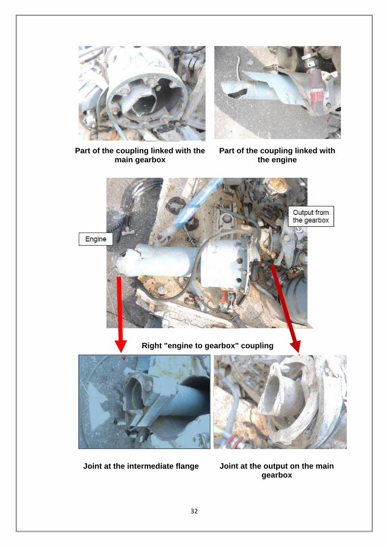
The two ―engine to main gearbox‖ couplings were broken:
The left coupling was broken in the intermediate part of the coupling shaft.
The fracture was static without damage prior to the accident. This was a
consequence of the accident.
Rotational interference was identified on the outer surface of the
coupling shaft. This observation showed that the left engine was running
during the fracture sequence. This observation is consistent with parameters
recorded on the FDR.
32
Part of the coupling linked with the main gearbox
Part of the coupling linked with the engine
Right "engine to gearbox" coupling
Joint at the intermediate flange Joint at the output on the main gearbox

33
The right coupling was broken at the MGB input flexible coupling and at
the intermediate coupling flange. The fractures were static without damage
prior to the accident.
Rotational interference was observed on the inner surface of the front
fairing. This shows that the right engine was running during the fracture of the
coupling. This observation is consistent with parameters recorded on the
FDR.
The front left suspension bar was complete without distortion. The
three other suspension bars were fractured statically without damage prior to
the accident. This damage was a consequence of the accident.
Each suspension bar had its lower and upper joints in position.
The two laminated elastomer stops were fractured and the main
gearbox had turned clockwise in relation to the structure. This damage was a
consequence of the crash when the powered main rotor stopped suddenly
due to impact with water.
Front laminated elastomer stop Rear laminated elastomer stop

34
Mast rotor
Main rotor
The components of the mast rotor were in position. The rotating and
non-rotating swash-plates were in the lower position with a tilt to the right.
The star arm attached to the fractured black blade
35
The star arm associated to the black blade was fractured with an angle
representative of load in the inertia direction.
The three other star arms were externally complete.
The star was nominally attached to the mast.
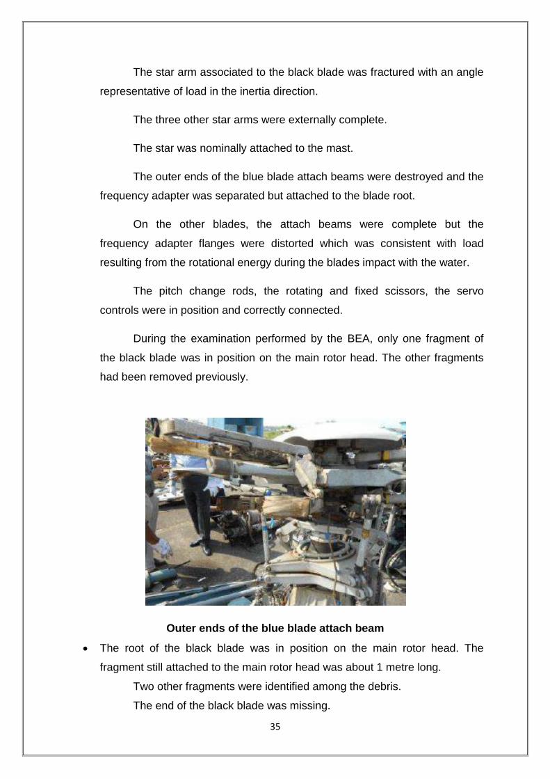
The outer ends of the blue blade attach beams were destroyed and the
frequency adapter was separated but attached to the blade root.
On the other blades, the attach beams were complete but the
frequency adapter flanges were distorted which was consistent with load
resulting from the rotational energy during the blades impact with the water.
The pitch change rods, the rotating and fixed scissors, the servo
controls were in position and correctly connected.
During the examination performed by the BEA, only one fragment of
the black blade was in position on the main rotor head. The other fragments
had been removed previously.
Outer ends of the blue blade attach beam
The root of the black blade was in position on the main rotor head. The
fragment still attached to the main rotor head was about 1 metre long.
Two other fragments were identified among the debris.
The end of the black blade was missing.

36
On these fragments of the black blade, no impact was identified on the
leading edge. The profile of this blade was destroyed from the root toward the
end.
The fragment of the black
blade attached to the rotor head
Others fragments of the black blade
Only one fragment of the blue blade was identified. This fragment was
composed of the root of the blade and was about 2.4-2.5 metres long. On this
fragment, the profile was complete and no impact marks were identified on
the leading edge.
Blue blade – lower surface
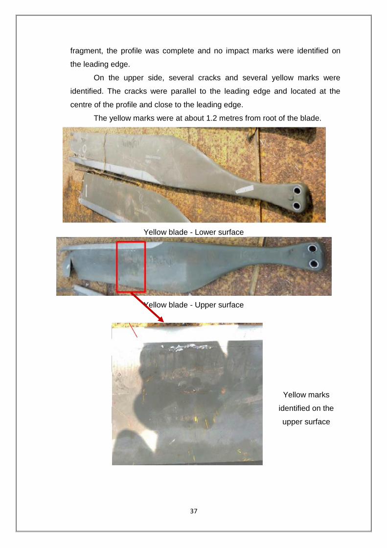
Only one fragment of the yellow blade was identified. This fragment was
composed of the root of the blade and was about 2.6-2.7 metres long. On this
37
fragment, the profile was complete and no impact marks were identified on
the leading edge.
On the upper side, several cracks and several yellow marks were
identified. The cracks were parallel to the leading edge and located at the
centre of the profile and close to the leading edge.
The yellow marks were at about 1.2 metres from root of the blade.
Yellow blade - Lower surface
Yellow blade - Upper surface
Yellow marks
identified on the
upper surface

38
Two fragments of the red blade were identified. The main fragment was
composed of the blade root and was about 2.4-2.5 metres long. The other
fragment was about 1.2 metres long.
On the main fragment, the profile was complete and no impact was
identified on the leading edge.
On the other fragment, the profile was destroyed but no impact was
identified on the rest of the leading edge.
Red blade - Lower surface
Red blade - Upper surface
Yellow marks identified on the upper surface

39
On the upper side, several cracks and several yellow marks were
identified. The cracks were parallel to the leading edge and located at the
centre of the profile and close to the leading edge.
The yellow traces were located about 1.6 metres from the blade root.
Note: On one picture taken by the Indian Authority, several yellow
deposits are visible on a leading edge. During examinations made by the
BEA, these deposits were not identified.
The condition of the blade fragments shows that the main rotor had
significant energy (rotation and torque) during the impact with the sea.
Tail rotor drive system
The flexible coupling located at the tail rotor drive shaft output flange
on the main gearbox was complete. The internal splines were not damaged.
Exit of the main gearbox toward the tail
rotor drive
Internal splines
The front drive shaft was broken and its front part was missing. The
shaft fracture was static without damage prior to the accident.

40
FORWARD
Broken front drive shaft
The flexible coupling between the front drive shaft and the centre drive
shaft was destroyed by overload.
Flexible coupling between the front drive shaft and the centre drive shaft
The rear drive shaft was broken in its centre area and bent. The fact
that the shaft was complete on recovery from the sea indicated that the shaft
fracture identified by the BEA was a consequence of transportation of the
debris.
The splined end fitting was either not damaged or only superficially.
All bearings were extracted from their clamps. The bearings were
corroded due to contact with salt water.

41
Splined end fitting
The TGB forward attachment coupling shaft was in position and
complete.
The input housing of the TGB was disconnected from the main housing
and had been pushed toward the rear.
Tail rotor
All of the tail rotor blades were in position on the hub. One blade was
fractured by bending close to its root.

42
Left side of the tail rotor Picture The rear side of the tail rotor
Scuffing identified on the fenestron
duct
Scuffing identified on the fenestron
duct
Several rotational interferences were identified on the fenestron duct
due to contact with the blades. This observation showed that the fenestron
was rotating when the structure of the tail rotor began to be damaged and
deformed.
Flight controls
Main rotor controls
For easier understanding, the rods and the bellcranks are identified
arbitrarily in the diagram below (rods identified from R1 to R18 / bellcranks
identified from B1 to B10) with the position of damage.

43
The pilot‘s and copilot‘s cyclic pitch control sticks were in position and
complete. These sticks were connected to each other.
The pilot‘s collective pitch lever was in position and complete whereas
the copilot‘s lever on the left was disconnected from the structure.
Diagram of the flight controls
In the right side, damage identified was as follows; the other
components were complete and connected to the structure. All fractures
identified were the consequence of an overload (static fractures) without
damage prior to the accident.
rod R4 broken
RH mixing unit disconnected from the structure and the bellcrank was
broken
rod R2 broken;
rod R1 broken close to the rod end and the bellcrank B1;
rod end R17 broken on the collective lever torque shaft

44
FRACTURE
Broken rod R4
Broken bellcrank B3
Broken rod R17 and RH mixing unit disconnected from the structure
On the left side, damage identified was as follows, the other
components were complete and connected to the structure. All fractures
identified were the consequence of overload (static fractures) without damage
prior to the accident.
rod R13 broken twice after the LH roll control actuator and close to the
bellcrank B10;
rod R8 broken twice after the pitch control actuator and close to the bellcrank
B6;

45
LH mixing unit totally destroyed and disconnected from the structure;
Bellcranks B5 and B9 connected to a fragment of the structure.
(On each bellcrank, two fragments of rod were connected; R7, R8, R12 and
R13.)
rod R6 broken twice;
rod R5 broken close to the lower rod end;
rods R10 and R11 broken.
Fragments of rods R6, R8 and R13 were missing.
Front controls on the left side
Rod R8 equipped
with the pitch
control actuator
Rod
R 16 Rod R 15
Rod R13 equipped with
the LH roll control
actuator

46
Parts of controls probably on the left side
Part of controls on the left side
To conclude, the main rotor controls were clearly continuous before the
impact. This observation was consistent with parameters recorded on the
FDR.

47
Tail rotor controls
The parts of the tail rotor controls checked in the wreckage are
indicated on the diagram below. The other parts were not examined because
access was too difficult or the area had been totally destroyed during the
accident.
Several fractures were identified on the controls. All fractures observed
were the consequence of overload (static fractures) without damage prior to
the accident.
The end of the tail rotor control was cut previously by the Indian
Authority.
Diagram of the tail rotor controls

48
Part of the tail rotor control
Part of the tail rotor control

49
Engines
The helicopter was equipped with two Turbomeca Arriel 2C engines
identified below:
Left engine : S/N 24524;
Right engine : S/N 24540.
The examinations consisted of an external review, a check on the
magnetic plugs and filters and a boroscopic examination. These investigations
were performed with the manufacturer‘s expert. The manufacturer‘s technical
document is referenced RA2015-300. Turned by hand, the engines could not
rotate. This blockage was due to seizing of the bearings after being in the sea.
External review:
Left engine Right engine
The front support: see under ―main
rotor drive system‖
The rear engine support was
deformed with the elastomer shock
The front support: see under ―main
rotor drive system‖
The rear engine support was deformed
with the elastomer shock mounts

50
mounts broken.
The air intake was attached to the
engine.
The air intake was deformed during
the impact.
The engine casings and the
transmission
shaft casing were neither deformed
nor perforated.
The exhaust pipe was deformed but it
kept its initial form.
On the front of the engine, the starter
generator was in position and
connected to the engine.
The shaft of the pump and metering
unit assembly was outside of the
engine. The clamp of this shaft was
found deformed and was found under
the joint area.
On the top of the engine, the fuel
valves assembly and the bleed valve
unit were in position.
The bleed valve was open, this
position is normal with the engine
stopped.
On the pump and metering unit
assembly, the fuel supply pipe was
connected but broken about 0.1
metres from the engine.
The external pipes were connected
and complete. Some deformations
were identified; these deformations
were a consequence of the impact.
broken.
The air intake was attached to the
engine.
The air intake was deformed during the
impact.
The engine casings and the
transmission shaft casing were neither
deformed nor perforated.
The exhaust pipe was deformed but it
kept its initial form.
On the front of the engine, the pump
and metering unit assembly and the
starter generator were in position and
connected to the engine.
On the top of the engine, the fuel
valves assembly and the bleed valve
unit were in position.
The link was broken at the entry to the
start electro-valve. The fracture was a
consequence of the impact during the
accident.
The bleed valve was open, this position
is normal with the engine stopped.
On the pump and metering unit
assembly, the fuel supply pipe was
connected but broken about 0.4 metres
from the engine.
The external pipes were connected
and complete. Some deformations
were identified, these deformations
were a consequence of the impact.

51
The left side of the left engine
Pump shaft of the and metering unit assembly disconnected from the engine
Magnetic plugs
The electrical magnetic plugs and the front mechanical magnetic plugs
were checked. The rear mechanical magnetic plugs had been ripped off from
the engines and checks were impossible.
One metallic chip was identified on the front mechanical magnetic plug
of the right engine. This chip is not representative of an internal mechanical

52
damage. No metallic chip was identified on the other plugs. There were just oil
residues mixed with water.
LEFT ENGINE RIGHT ENGINE
Front mechanical magnetic plug
Front mechanical magnetic plug
Electrical magnetic plug Electrical magnetic plug
Filters:
On the oil filter covers and the fuel filter covers, the blockage indicators
were not activated. The filters were clean.

53
Boroscopic examinations:
Both engines had a similar internal condition. The description below is
valid for both engines.
The axial compressor blades were damaged on the leading edge. This
observation shows that some debris passed through the compressor whilst
the engines were rotating, most probably due to the consequences of the
impact with the water.
Left engine Right engine
Axial compressor Axial compressor
The centrifugal compressor blades also showed some damage on the
leading edge.
No damage was identified in the combustion chamber and on the
turbine blades.
Some residues were identified on the leading edge of the gas
generator turbine blades.
These residues probably came from the damaged compressor blades.
Inview of this, we can say that there was combustion in the combustion
chamber and so fuel was being supplied to the engine at the moment of the
impact.
54
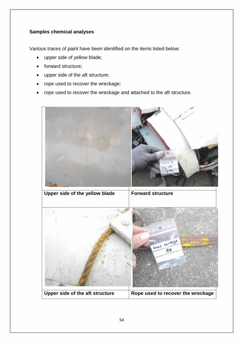
Samples chemical analyses
Various traces of paint have been identified on the items listed below:
upper side of yellow blade;
forward structure;
upper side of the aft structure;
rope used to recover the wreckage;
rope used to recover the wreckage and attached to the aft structure.
Upper side of the yellow blade
Forward structure
Upper side of the aft structure Rope used to recover the wreckage

55
During the examination of the wreckage by the BEA, samples were
taken on these elements.
The analyses carried out on these samples have been limited by the
very small amount of material. It has not been possible to identify precisely all
the chemical components of these samples. Nevertheless analyses show that
these various samples are composed of an epoxy resin, commonly used in
paint composition.
Concerning the traces identified on the upper side of the yellow blade,
we note that there is neither modification of the helicopter vibration nor main
rotor behavior on the FDR parameters. In addition, no damage was identified
below these traces.
Under these conditions, the yellow traces cannot be associated with
the accident.
1.18.9 Human Factor and CRM
Human Factors include human behaviour and performance; decision-
making and other cognitive processes; communication and documentation; as
well as the refinement of staff selection and training. Each of these aspects
demands skilled and effective human performance.
Human Error is, by far, the most pervasive cause of accidents and
incidents in aviation. Also, what could be considered perfect performance in
one set of circumstances might well be unacceptable in another. Studies of
worldwide aviation accidents indicates that for the approach and landing
phase of flights, which accounts for 4 per cent of total flight exposure time and
49 per cent of all accidents, flight crew error is cited in 80 per cent as a factor.
Similar studies indicate that between 80 and 90 per cent of all aviation
accidents are attributable to human error in one form or another. It is
abundantly clear from such data that human performance is critical to
preventing accidents.
CRM training encompasses a wide range of knowledge, skills, and
attitudes including communications, situational awareness, problem solving,
decision-making, and teamwork; together with all the attendant sub-disciplines

56
which each of these areas entails. CRM can be defined as a management
system, which makes optimum use of all available resources—equipment,
procedures and people—to promote safety and enhance the efficiency of
operations. CRM is concerned with the cognitive and interpersonal skills for
making decisions.
1.19 Useful or Effective Investigation Techniques
Nil

57
2.0 ANALYSIS
2.1 Helicopter & Its Maintenance
The Helicopter had flown for 3255 airframe hrs before the date of
accident flight. The Certificate of Airworthiness of helicopter remains valid until
or unless it is suspended/ cancelled subject to valid Airworthiness Review
Certificate (ARC) and the last was ARC issued on 19.3.2015.
The last major inspection done on helicopter was 3000 hrs/ 6 year
inspection at 3057.50 Airframe Hours in September 2015. Subsequently all
lower inspections and pre-flight checks were carried out as and when due
before the accident. The helicopter was loaded within the limit and C.G was
within approved range.
The helicopter was equipped with two Turboshaft Arriel 2C engines
manufactured by Turbomeca, France. The helicopter and the engines were
being maintained under continuous maintenance program consisting of
calendar period based maintenance and Flying Hours/Cycles based
maintenance. LH Engine had logged 4325:50 Engine Hrs, 6944.10 Ng cycles
and 2202.50 FT cycles. The RH Engine had logged 4100:25 Hrs with 7188.70
Ng cycles and 2057.90 FT cycles.
All modifications and Service Bulletins were complied with before
undertaking the flight. No snag was pending for rectification before the
accident flight. The emergency floatation gear switch was not armed as the
crew was not planning to carry out ditching so the floatation gears have not
inflated.
It can be concluded that the helicopter was maintained properly and it
was airworthy to take the flight. Maintenance aspects of the helicopter have
not contributed as cause of the accident.
2.2 Crew Qualifications
Both the crew held valid licenses and were qualified on type. Their
ratings were current. The PIC had a total flying experience of 19588 hrs and
the co-pilot had a total flying experience of around 6700 hrs. Last night flying

58
was carried out by the co-pilot on 30.11.2014 and by the PIC on 31.8.2015.
Total night flying by the co-pilot was 190 hrs approximately.
Both had valid class I medical and have undergone proficiency checks
as per the requirements. The crew had undergone pre flight medical including
breath-analyser test before taking off for the first flight of the day and they
were not under influence of alcohol.
2.3 Training
In any operational organisation training records are very vital and is
one of the indicator to provide the health of operations. Earlier investigation
reports have emphasized on the issue and gave recommendations not only
on the conduct of training but also on upkeep of documentation.
The training of Dauphin N3 pilots is under the head of training, Western
Region which is under the overall control of GM (WR). From last one and a
half year, an officer (Capt.) is holding the post of both head of training as well
as the head of operations. Both the crew fulfills the training and currency
requirements for flying in the six months including offshore currency.
One of the crew was cleared for night offshore as co-pilot and as per
records provided his night currency had lapsed as he had last flown offshore
by night on 30 Nov 2014. The night training flight was undertaken to enable
him to regain his currency
For clearance as PIC the SOP only stipulates the followings:-
a) Pilot should have flown for one year/monsoon as a co-pilot.
b) Pilot should have at least 4 actual / simulated night medevac
from Bombay high to Juhu. The SOP does not specify the
aspects such as the detailed sortie profile, phase of moon for
ambient lighting or the selection of deck for night training.
All flying by day and night within offshore fields and landing back at
offshore helidecks is conducted under ONGC radio officer without prior
intimation to Mumbai FIC or the operator.

59
Offshore training is being carried out without a written programme.
There is no procedure or control on conduct of training and PIC is left to
decide all aspects of the flight. In this particular flight the marine radio officer/
AME were not aware of the flight profile. As per the CVR the radio officer
enquired about the flight profile when flight crew was preparing to start up.
Further as one of the crew had a break in night currency it would have been
prudent to carry out some amount (0:15 minutes) of dusk flying prior to night
flying including a few approach/ landing at WIS platform before proceeding to
Ron tappmeyer.
As per the CVR, the helidecks selected for night training were rig Ron
tappmeyer and floater vessel Samudra Sevak. These were not ideal platform
for initial night training due to poor surrounding ambient lighting and Sevak
being a floater is an unstable deck.
Review of the files of the individual revealed that there is no system of
review of the training report/ record received for the pilot and nor is there any
procedure through which the progress of the pilot on any weak areas
indicated in the simulator training can be monitored. It is more of a filing the
records in a file with index.
2.4 Helideck Safety
ONGC has more than 300 helidecks in entire Mumbai flight field
extending from 40 nm to 120 nm on the west coast. Some of these decks are
living platforms with refueling facilities while others are production platforms or
floating vessel or drilling rigs.
As per para 8 of ONGC Aviation standard 4 (AS: 4) inspection of
helidecks should be carried out prior to conducting passenger operations to
any offshore facility operated by ONGC. Further para 8.4 of CAR Section 4
Series B Part V on minimum safety requirements for helicopter landing areas
used on regular basis stipulates that ― operator shall carry out periodic audit/
inspections to ensure compliance of minimum facility during the period of
operation as part of SMS.

60
In practice only prior to starting operations to any helidecks, the
operator satisfies himself on the minimum operating and safety facilities
through a trial landing report.
The committee was not provided any other requirement either from
DGCA or from ONGC wherein requirement of helidecks safety audit/
surveillance/ inspection are laid down. The committee during course of
investigation visited SLQ and EE production platform to which Ron tappmeyer
was attached on the night of accident. The condition of the both the helidecks
surfaces were found rusted with rust flakes coming out at a number of places.
The matter was discussed with DGM (Aviation safety) who, as per him carries
out inspection of helidecks for their condition and safe operation of
helicopters, though there is no system/ procedure developed for the purpose.
Pawan Hans also have not carried out any inspection/ audit of the
helidecks, though it should have been carried out under SMS. The system of
HAC is not effective as there was no close loop mechanism for taking action
on the hazards raised.
From the regulatory point of view there are no laid down requirements
of periodicity of the safety audits of helidecks or system of action taken
reports to ensure compliance on the deterioration observed on the safety
standards. There is an urgent need to have formal regulation on the subject,
similar to CAP 437 with inbuilt check & balance provisions between the
helicopter operators and the installation (rigs etc.) owners.
2.5 Weather - Obtaining & transmission procedure/ documentation
Helidecks are regarded as ‗unlicensed landing areas‘ and offshore
helicopter operators are required to satisfy themselves that each helideck to
which they operate is fit for purpose. Up-to-date, accurate meteorological
information is critical for helicopter operators for flight planning purposes and
by crew to facilitate the safe operation of helicopters in the take-off and
landing phases of flight. Meteorological reports of the concerned platform are
desirable than those of the neighbouring platforms.
61
The criteria have to be described for such operations including the
meteorological requirements and these requirements should be accounted for
in the Operations Manuals of the operators. In the present case though the
QNH, wind direction and velocity was provided to the flight crew, the cloud
base and visibility was neither available with the marine radio officer nor it
could be ascertained.
2.6 Wreckage Examination
The condition of the wreckage and the deformations indicated that the
helicopter impacted water with significant energy level. The area in front left
side has taken maximum loads indicating that helicopter hit the water in a left
bank and pitch down attitude. These observations are consistent with the
airspeed and attitude parameters recorded on the FDR during the impact. On
the tail rotor, the blades of the fenestron were in position without visible
deformation. There were rubbing marks on the fenestron duct from blade. The
rear drive shaft was continuous and complete on recovery from the sea but
bent. The splines were not damaged.
As mentioned earlier, the wreckage was examined at Juhu followed by
further analysis by investigators in association with BEA France. Following
have been concluded:
The helicopter was destroyed and five main fragments were identified:
front lower structure including the instrument panel and the centre
console;
main rotor installed on the transmission desk;
both engines;
assembly with the aft structure and the tail boom;
tail rotor.
When the wreckage was recovered from the sea, the main rotor was
connected to the main gear box and was equipped with four blade fragments.
The main gear box was complete with the rods and the servo-controls in
position.

62
The suspension bars and the two laminated elastomer stops were
destroyed and show that there was energy (rotation and torque) when the
blades impacted the sea.
The four blades were broken with several fragments missing especially
the end of each blade. On the fragments analysed, no impact was identified
on the leading edge.
The main rotor controls were obviously complete before the impact.
This observation is consistent with parameters recorded on the FDR which
showed that the helicopter was most probably controllable until the end.
On the tail rotor, the blades of the fenestron were in position without
visible deformation.
Several rotational interferences were identified on the fenestron duct
due to contact with the blades which shows that the fenestron was turning
when the structure of the tail rotor began to be damaged and deformed.
The rear drive shaft was complete on recovery from the sea and bent.
At the forward and the rear, the splines were not damaged.
The tail rotor controls were fractured in several areas during the impact
with associated deformations. Fractures located at each end of the control
system were all static and due to the accident. The tail rotor control was
obviously complete before the impact.
The two engines had a similar internal condition. The only damage was
to the axial compressors with grabbing, which showed that wreckages were
passed through the compressor whilst the engines were rotating. The engines
were running at the moment of impact which is consistent with FDR recorded
parameters.
63
2.7 Flight Recorders & Spectrum Analysis
2.7.1 CVR
The flight time between the take off and the end of the recording was
05 min & 19 secs. The audio data analysis of the period did not show any
abnormality in the cockpit. The transmissions with ground were loud and
clear. It was observed that normal check list was not carried out by following
challenge and response procedure.
No audio warnings were recorded on the audio data except the
―Decision Height‖ warning which triggered 4 seconds before the end of the
recording and is consistent with the height of the helicopter at that moment
(200 ft).
2.7.2 Spectral Analysis
A spectral analysis was performed to evaluate the condition of the
propulsion system and identify any acoustic anomalies that might have been
recorded. The spectrum view showed acoustic signatures (harmonic families)
typical of the helicopter propulsion system spectrum, i.e. Main Rotor blade
rotation with a fundamental frequency of 23.66 Hz (BR – Blade Rate), Tail
Rotor drive shaft with a fundamental frequency of 1083 Hz and MGB input
meshing rotation with a fundamental frequency of 2740 Hz.
The signatures were consistent with nominal acoustic signature
normally observed on AS365 family of helicopters. These fundamental
frequency values indicate that the propulsion system was at 100% of its
nominal rate and is in consonance with FDR data.
No abnormality was observed from beginning until the end as per the
recording. Two acoustic events were detected as given below:
(a) Blades-Vortex Interaction (BVI) occurrences before the end of the flight
48 secs before the end of recordings, a ―flapping‖ sound related to the
blades was recorded on the audio file. This sound is typical of a
blades-vortex interaction (BVI) phenomenon and is generated by the
interaction between blades and vortex. The BVI phenomenon occurs

64
when a blade strikes on or passes closely to the shed tip vortices of
preceding blades. It mainly occurs during descent flight or sharp turn.
(b) Unknown unstable frequency
An unknown unstable frequency was present in the spectrum. This
frequency can be found on other DAUPHIN‘s CAM recordings. Its
sharp value changes are usual on this helicopter family. The origin of
this frequency has not been identified yet but is not related to a failure
in the propulsion system.
Neither the audio data analysis nor the spectrum analysis showed any
sound of blades contacting with an external object.
2.7.3 FDR (END of the Recording is depicted as time T0)
The flight was a night training flight. 56 secs after takeoff from SLQ
platform, the autopilot was engaged in ALT and HDG modes. In these modes,
the pilot adjust power by the movement of collective stick. The helicopter was
in cruise for about 3 minutes. The cruise altitude was between 550ft and 650ft
AMSL with Auto-Pilot engaged. About 98 secs prior to the crash, the autopilot
(upper modes ALT and HDG) was disengaged.
At that point the pilot slightly moved the cyclic stick backward and the
collective stick downward. Consequently, the pitch increased and the power
decreased. This maneuver looks like a standard approach procedure to
decrease the speed. Thereafter, the pilot moved the cyclic stick slightly to the
left and began a left turn. For about 38 seconds from T0, the roll attitude was
always more than 12° left and the altitude continued to decrease. The
collective pitch was slightly moving upward. At 34 seconds from T0, the roll
attitude was 24.26° left. At 4 seconds from T0, the FDR recorded a maximum
left roll of 46.76 °.The pitch attitude was 8.79 ° down.
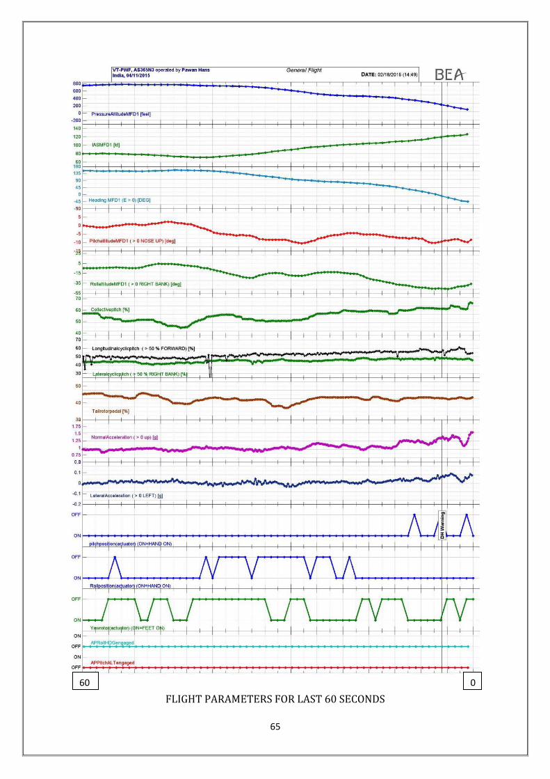
65
FLIGHT PARAMETERS FOR LAST 60 SECONDS
0 60

66
During the last ½ to 1 second the collective pitch significantly increased
from 61.25% to 66.84%. At that moment, when the recording stopped, the
recorded attitude of the helicopter was 8.44° pitch down and 36.58° left for the
roll. The lateral cyclic stick was 4.41% left.
2.8 CRM
The primary goal of CRM is enhanced situational awareness,
leadership, assertiveness, decision making, flexibility, adaptability, and
communication. Having decided to go around, the flying pilot needed to get on
to instruments and if he was disoriented, should call out so that the non-flying
pilot can take over. This aspect is also emphasised in special points in the
Medevac SOP.
The CVR readout brings out a lack of adherence to standardized
checks and procedures and communication protocol between the crew. While
the pilot on controls decided to go around, both pilots, perhaps, continued to
fly VFR. Pilot monitoring displayed lack of situational awareness by not taking
over controls. The crew thereby failed to engage in the important process of
CRM.
2.9 Safety Management System (PHL & ONGC)
The SMS manual has not been revised since initial issue in 2014,
inspite of the fact that various changes in organisation setup have taken
place. Neither there was any Risk Assessment carried out for any of these
changes. Safety Communication through meetings, seminars and bulletin etc
along with Safety Training has been stated as a major way to achieve the goal
of Safety Promotion. No safety circular or bulletin has however been issued
during last 2 years.
Safety training is required to be provided to all staff with refresher each
year, but it was found that even initial training has not been completed for all
the employees as mentioned in the Manual.
Pawan Hans has defined 18 key performance indicators as part of
Safety Assurance, though no values were indicated for any year to assess the

67
level of safety. Data pertaining to Safety Performance Parameters are also
required to be communicated to all concerned, but in absence of any
monitoring system, no such data is shared. There is no record to indicate that
consultation with all personnel regarding changes in work environment,
procedures, practices etc. is being carried out.
The SMS Manual further requires that the Flight Safety Document
system shall be reviewed at least once a year but it was not carried out even
once. It was informed that for a period of almost a year prior to the accident,
actions such as review of Flight Safety Manual, Safety Management System
Manual and record keeping on key performance indicators, training of PHL
executives, pilots, AMEs and other staff were not conducted though it was
required as per regulations. There was no key performance indicator specific
to the offshore operations.
2.10 Circumstances Leading to the Accident
In the present case the helicopter started up and took off from SLQ
platform and turned right towards Ron Tappmeyer Rig stationed on oil
Platform EE. Once it reached in the vicinity of Rig it started reducing speed.
There after it has initiated a left turn as seen in the AIS recordings on the
platform. The helicopter had turned towards the Rig but did not land and
crossed helideck. Simultaneously it started losing height while turning left.
As discussed earlier, disorientation or black hole approach Illusion can
happen during a final approach at dark night over water beyond which the
horizon is not visible. These conditions may produce the visual illusion of a
high-approach perspective.
The position of Ron tappmeyer was to the south extremity of the
South field with no other rigs nearby to provide ambient lighting. As per the
AIS and FDR the tail wind approach was made with speed of approximately
79 kts. This high speed approach would have caused an abrupt loss of
visual reference.

68
The pilot on controls was flying during night after break of nearly a
year. The fact that it was a dark phase of moon made this even more
challenging. Some amount of dusk flying on instruments would have
prepared the pilot flying for undertaking the night flying profile/ maneuvers.
As soon as he got airborne and set course for Ron tappmeyer, the pilot
flying has probably entered conditions ideal for black hole phenomenon
because of loss of horizon as is corroborated by CVR replay. Under such
conditions he was not aware about the direction he was proceeding to i.e.
up or down / turning right or left.
The pilot flying probably continued to fly visually instead of getting on
to instruments. Therefore on initiating the go around after realizing that he
was high he entered into spatial disorientation extremely quickly.
The instructor was not disoriented and was aware that the helicopter
was low. He had cautioned, (though delayed), the pilot flying twice. He
however did not realize that the pilot flying was in total state of spatial
disorientation and was unable to react to his caution. Nor did he take over
controls. The helicopter as a result crashed into the sea with a speed of
approximately 116 kts. The high impact velocity caused substantial damage
to the helicopter and fatal; injuries to the occupants.

69
3. Conclusion
3.1 Findings
3.1.1 General
The operator was carrying out operation of helicopter under NSOP and
the maintenance of helicopter under CAR 145.
The Certificate of Airworthiness, Certificate of Registration and
Certificate of Release to Service of the helicopter was valid on the date
of the accident.
The defect records were scrutinized and there was no defect pending
on the helicopter prior to the flight which could have contributed to the
accident.
All major modifications and Service Bulletins were complied with. There
was no snag pending for rectification before the accident flight.
There was no abnormality reported on the navigational or
communication equipments prior to the accident.
The PIC & the co-pilot were holding a valid license on the type of
helicopter. Both the crew members held valid medical certificates as
per the requirement.
The crew had undergone pre-flight medical examination and nothing
abnormal was observed. The BA test was negative.
The quantum of training as required by the relevant regulations on the
subject was imparted to both the flight crew members.
The Helicopter Underwater Escape Training (HUET) for the PIC was
not current on the date of accident.
As per the existing SOP, in addition to the standard Night Flying
Procedures, before landing on a Rig/Floater, a dummy circuit must be
carried out and pilot monitoring must call out bank during turns; and
speed & ROD during approach.
The emergency floatation gear switch was not armed as the crew was
not planning to carry out ditching so the floatation gears have not
inflated.
70
3.1.2 Organizational influences
The training manual available with the WR was not having any date of
issue though it was approved by the DGCA in as it is condition.
In WR the same flight crew personnel (DGM Level) was holding the
posts of DGM Training and DGM Ops.
The SMS manual though accepted by DGCA does not contain ‗How to
do‘ the various functions mentioned therein. The Manual just remains a
document without performance of any function at working level.
There is no SOP for carrying out night offshore training. There are
some references in the SOP issued for Night Ambulance Operation.
There is no document indicating procedure of taking weather (off
shore) and transmitting the same to flight crew. The flight crew
operating in offshore is not provided with accurate information on the
visibility, cloud ceiling and cloud base.
Earlier Committees of Inquiry have recommended ―establishment of
strong safety department‖ but it was observed that the operator has not
established the safety department in true letter and spirit. It is still
continuing on ad-hoc basis and full fledged department is yet to be
established.
There is a shortage of pilots and situation is aggravated due higher
attrition rate of flight crew.
Paras 3 & 4 of Subpart D – Special Helicopter Operations under PART
2 - OPERATIONS of CAR - Section 8, Series 'H' Part I on Commercial
Helicopter Operations regarding flight rules, night offshore operations
and corresponding training / recency requirements are ambiguous.
The cross-country requirement of ―route flying check sortie by night‖ in
para 4.5 (Page 4-B-3) of DGCA CAR Section 8, Series H, Part I is not
being complied by offshore operators as required.
Last night flying was carried out by the co-pilot on 30.11.2014 and by
the PIC on 31.8.2015. Total night flying by the co-pilot was 190 hrs
approximately.

71
Aviation Safety aspects covering systems and procedures of
operations have not been covered in the ONGC QHSE Implementation
though the off shore installation are with ONGC.
There is no documented safety system or procedure with ONGC to
ensure Safety Assurance particularly for helidecks audits, certification
and periodic inspections.
Medevac is defined in the contract signed between ONGC and PHL,
and PHL is providing the helicopter for medevac purposes but, it is not
one of the explicit requirements of the contract.
System of HACs is not a formal one and devoid of transparency and
closed loop procedures.
No specific training for handling communication and traffic of
helicopters is given to the marine radio officers.
3.1.3 Unsafe Supervision
The decision to undertake the flights in offshore field rested with the
pilot. There was no monitoring/ supervision to check if unsafe
decisions were not taken.
The training records of the flight crew is just a record keeping exercise
without any system or procedure in place to review the observation of
the instructor / examiner for monitoring the progress of the flight crew.
There is no system to identify the observations made by the SFIs in
their reports and depute the crew members accordingly for the various
special operations being conducted by PHL.
Flight Plans are filed with Bombay FIC only for flights taking off/landing
back at Juhu from Bombay High. The major portion of Bombay High
Oil field is class G airspace and no flight plans are filed for flights within
this region.
The Marine Radio officers provide information of position of Helicopters
and Transmit wind direction/velocity to the flight crew. They are neither
authorised nor competent to ensure requisite separation between the
helicopters

72
The deficiency existing on the Helidecks were reported by the operator
however no closed loop system exists to make these good in a timely
effective manner.
DGM (AS) ONGC is supposed to carry out all the proactive safety
oversight activities including inspection of flight decks and physical
inspection of helicopters but is not trained on any of the aspects.
3.1.4 Preconditions for Unsafe Acts
Many recommendations made by the earlier courts / committees of
inquiry having operational safety implications are yet to be
implemented by PHL in true spirit. Even the actions taken on the
recommendations have withered away with passage of time due
complacency and non supervision.
Due to non availability of senior level operational personnel and
adhocism, there is no supervision of operational activity.
Since the promulgation of the air routes in Bombay High in year 2010
new installations have been erected by ONGC wherein helicopter land
resulting in criss-crossing the existing routes.
Routine Cockpit Checks (Challenge and Response) for various phases
of flight were not thoroughly carried out. While the pilot on controls
decided to go around, both pilots, perhaps, continued to fly VFR. Pilot
monitoring displayed lack of situational awareness by not taking over
controls.
PHL is positioning a helicopter in Bombay High for the purposes of
night medevac, however no SOP has been developed for undertaking
night offshore operations at helidecks, particularly in the absence of
night landing aids.
Marine Radio Officer is not in a position to ensure separation.
3.1.5 The Accident Sequence
The pilot on controls was flying during dark phase of moon at night
after break of nearly a year.

73
Some amount of dusk flying on instruments would have prepared the
pilot flying for undertaking the night flying profile/ manoeuvres.
Before the descent and until the autopilot disconnection, the recorded
parameters were nominal.
The helicopter made a tail wind approach with speed of
approximately 79 kts for Ron tappmeyer which is to the south
extremity of the South field with no other rigs nearby to provide
ambient lighting which caused an abrupt loss of visual reference.
During the descent and before the helicopter started to turn left, the
parameters were consistent with a standard approach procedure
associated with a speed decrease by pushing slightly down the
collective stick and nose up the helicopter
The left turn was 50 seconds long with slight variations in roll attitude.
The lateral acceleration remains between -0.03 and +0.09. The
corrections did not lead to a roll attitude less than 12° to left
After the Autopilot disconnection, the pilot was ―hands on‖ and the
attitude of the helicopter was consistent with the inputs on the flight
commands.
No specific pilot inputs were recorded, except actions on the collective
pitch in the last second of the recording.
The pilot flying has probably entered conditions ideal for black hole
phenomenon because of loss of horizon wherein he was not aware
about the direction he was proceeding to i.e. up or down / turning
right or left.
The pilot flying probably continued to fly visually instead of getting on
to instruments, therefore on initiating the go around after realizing
that he was high he entered into spatial disorientation extremely
quickly.

74
The engines were delivering power until the end of the recording. The
engines parameters NG, NR, TRQ and T4 were consistent with each
other and with the power demand on the collective pitch.
The instructor cautioned, (though delayed), the pilot flying twice but
did not realize that the pilot flying was in total state of spatial
disorientation and was unable to react to his caution.
The PIC did not take over controls when the helicopter descended
below critical height.
No warnings were recorded in the flight data during the flight of the
event.
3.2. Probable Cause
The helicopter impacted into the sea at high velocity, as
The pilot on controls, who had a long break in night offshore
flying, got into complete spatial disorientation, as a result of
black hole phenomenon, while approaching a helideck at high
speed in tail winds on a dark night, and
The PIC did not take over controls when the helicopter
descended below critical height
4. Recommendations
For Offshore Flying
The Helidecks from where night currency training are to be carried out
may be identified by ONGC in association with the Helicopter operators
and these helidecks should be provided with minimum landing aids for
night offshore operations. DGCA may develop procedures for landing
and takeoff utilizing these aids.
As far as practicable night flying to/from the floating vessels should not
be carried out.
The existing SOP on off shore departure and arrival for Bombay High
should be immediately reviewed covering following aspects.

75
Existing routing and separation
Planning, Authorisation, Post Flight documentation of the flying
undertaken within off shore fields including intimation to FIC
Duties and responsibilities of a competent person to ensure
separation.
Accurate weather information including visibility, cloud base and
ceiling. The procedure of obtaining and transmitting this
information to the flight crew should be developed.
DGCA may review the requirements regarding flight rules for off shore
night operations and corresponding training and recency requirement.
ONGC should develop system and procedure for carrying out periodic
audit of the helidecks from safety point of view. This audit should be
linked to continued certification of the helidecks for operational
purposes. A copy of audit report should be provided to the operator for
verification and continuance of operations.
In addition to the automated means of ascertaining the meteorological
information, a manual means of verifying and updating the visual
elements of observation, i.e. cloud amount and height of base, visibility
and present weather, may be developed. The latest weather report
from each installation should be made available to the helicopter
operator one hour before take-off.
General - PHL
Documentation is a weak area throughout the organisation be it
operations or safety including SMS. The importance of timely updation
of documents and the dissemination of information needs no emphasis.
As one time exercise all the Manuals, procedures, processes be
reviewed and amended to have cohesion of content. System of
periodic review should be put in place and strictly followed.
PHL should immediately undertake the implementation of safety
management system across the whole organisation by completion of
training, reviewing the manual by including the procedures for the
actions to be carried out under SMS, appointing key safety personnel

76