gore microwave/rf assemblies...figure 1: the anatomy of gore® microwave/rf assemblies for general...
TRANSCRIPT

GORE® MICROWAVE/RF ASSEMBLIESGeneral Purpose Test and Interconnect Applications

For test applications that require consistent and highly repeatable measurements, GORE® Microwave/RF Assemblies for general purpose test applications provide reliable electrical performance with proven phase and amplitude stability. The smaller diameter and highly flexible, yet durable construction simplify the routing process while ensuring long-lasting electrical performance after installation, particularly in board-to-board and inside-the-box applications. GORE® Microwave/RF Assemblies provide electrical and mechanical integrity for long service life in a lightweight cable assembly.
Greater Flexibility
GORE® Microwave/RF Assemblies are extremely flexible and withstand the rigors of handling and installation. Unlike traditionally designed flexible cables that are more stiff and difficult to handle, Gore’s assemblies have a small bend radius that makes routing easy even in tight spaces. Their smaller size and flexibility enable these cables to maintain signal integrity for a longer service life.
Precise and Repeatable Measurements
GORE® Microwave/RF Assemblies offer excellent electrical performance in applications from DC through 70 GHz. The assemblies’ proven phase and amplitude stability ensures accurate and repeatable measurements. Gore tests each assembly after manufacturing to ensure that its insertion loss and VSWR meet performance criteria.
The construction of GORE® Microwave/RF Assemblies enables consistent electrical performance (Figure 1). Gore’s expanded polytetrafluoroethylene (ePTFE) insulation has a dielectric constant of 1.4, which translates to low relative loss, high velocity of propagation (85 percent speed of light), low capacitive loading, and high cut-off frequencies. Protected by the inner braid and jacket, the outer conductor delivers
Maximum flexibility, excellent electrical stability
a minimum of 100 dB/ft of shielding effectiveness through 18 GHz. A specific assembly’s shielding effectiveness is determined by the choice of connector.
Gore provides a variety of standard connectors designed specifically for GORE® Microwave/RF Assemblies. These connectors are engineered to complement the performance of each cable, minimizing loss and reflection for optimized signal transmission.
Benefits of GORE® Microwave/RF Test Assemblies
▪ Reliable signal integrity over longer distances with low loss up to 70 GHz
▪ Reliable, repeatable electrical performance with consistent phase and amplitude stability
▪ Easy installation with flexible construction and small bend radius
▪ Decreased weight with smaller diameter for higher density applications
▪ Design flexibility with a variety of interconnect options
2 GORE® Microwave/RF Assemblies

Figure 1: The Anatomy of GORE® Microwave/RF Assemblies for General Purpose Applications
Typical Applications ▪ Board-to-board ▪ Inside-the-box ▪ ATE systems (automated test equipment) ▪ Load boards ▪ Environmental test chambers ▪ Thermal vacuum chambers ▪ Telecommunication systems ▪ Optical modules ▪ Evaluation boards ▪ Antenna arrays ▪ Test bench systems ▪ Module-to-module interconnect ▪ Backplane interconnects ▪ Clock distribution ▪ 5G test and interconnection
Phase Matching
Upon request, phase or time delay matching can be specified for GORE® Microwave/RF Assemblies with frequencies of DC through 70 GHz. According to the performance requirements of the application, cable assemblies can be specified to meet absolute or relative matching values:
▪ Absolute match: One or more assemblies having a specific time delay or phase length target value ± some tolerance value. This type of specification allows replacement or addition of individual cables in a matched set.
▪ Relative match: Two or more assemblies whose time delay or phase length fall within a specified match window. Relative matching ensures consistent matching within a set of cables, but an assembly from one set may not necessarily be matched with cable assemblies in another set.
Gore can provide absolute and relative time delay matching to sub-picosecond tolerances.
High-Density Interconnects
Gore offers several extremely small interconnects that deliver consistent electrical performance with maximum flexibility (Table 1). These assemblies enable you to achieve high density for applications such as printed circuit boards and load boards. The combination of low loss, small diameter and minimum bend radius facilitate easier routing and durable installation, making them an ideal replacement for semi-rigid assemblies (Figure 2). A variety of push-on connectors are available (Table 2). For cable/connector combinations specifically designed for load board applications, contact a Gore representative at [email protected].
Figure 2: Typical Insertion Loss (dB) for High-Density Interconnects1
1 The electrical specifications in this table are based on a 0.3 m (12 in) assembly length and maximum frequency with straight connectors.
-3.0
-2.5
-2.0
-1.5
-1.0
-0.5
0.0
0 10 20 30 40 50 60 70
Inse
rtio
n lo
ss (d
B)
Frequency (GHz)
G4G189
55
5453
4L
GORE® Microwave/RF Assemblies 3

Mechanical/Environment Properties
1The electrical specifications in this table are based on a 0.3 m (12 in) assembly length and maximum frequency with straight connectors.
Gore Cable Type 4L 53 G1 G4 54 89 55
Center Conductor Solid Solid Stranded Solid Solid Solid Solid
Overall Diameter [mm (in)] 1.2 (0.047)
1.8 (0.070)
3.0 (0.120)
3.0 (0.120)
1.8 (0.070)
2.2 (0.085)
1.8 (0.070)
Nominal Weight [g/m (g/ft)] 6.6 (2) 13.1 (4) 26.2 (8) 26.2 (8) 13.1 (4) 16.4 (5) 13.1 (4)
Minimum Bend Radius [mm (in)] 6.4 (0.25)
10.2 (0.4)
12.7 (0.5)
12.7 (0.5)
10.2(0.4)
12.7 (0.5)
10.2 (0.4)
Temperature Range (°C) -55 to 125
Gore Cable Type 4L 53 G1 G4 54 89 55
Maximum Frequency (GHz) 18 18 18 18 40 40 70
Typical VSWR 1.33:1 1.32:1 1.30:1 1.30:1 1.33:1 1.40:1 1.40:1
Typical Insertion Loss (dB) 1.58 1.26 0.73 0.75 1.93 1.60 2.69
Impedance (Nominal) (Ohms) 50
Attenuation at Maximum Frequency [dB/m (dB/ft)]
5.04 (1.54)
3.69 (1.13)
2.33 (0.71)
2.08 (0.63)
5.45 (1.66)
4.46 (1.36)
7.34 (2.24)
Dielectric Constant (Nominal) 1.4
Velocity of Propagation (Nominal) (%) 85
Shielding Effectiveness (dB through 18GHz) > 100
Time Delay (Nominal) [ns/m (ns/ft)] 4 (1.22)
Table 1: High-Density Interconnect Specifications1
Electrical Properties
4 GORE® Microwave/RF Assemblies

Table 2: Connector Options for High-Density Interconnects
Gore Cable Type
4L 53 G1 G4 54 89 55
Connector Type Max. Freq. (GHz)2 18 18 18 18 40 40 70
SMA Male 18 S01 S01 R01 R01 S01 S01
SMA Box Right-Angle Male 18 R71 R71 S71
SMA Female 18 S02 S02 R02 S02
SMA Bulkhead Female 18 R42 R42 R42
SMP Bulkhead Full Detent Male 26.5 ZT4
SMP Bulkhead Smooth Bore Male 26.5 ZKT ZKT ZKT
SMP Bulkhead Ultra Smooth Bore Male 26.5 ZUJ ZUJ ZUJ
SMP Float Mount Modified Full Detent Male 26.5 ZQF ZQF ZQF
SMP Female 26.5 ZEM ZT8 ZEM ZEM ZT8 ZT8
SMP Box Right-Angle Female 26.5 ZF6 ZF6 ZF6 ZF6 ZF6
SMPM Full Detent Male 40 ZU2
SMPM Smooth Bore Male 40 ZUK ZUK
SMPM Female 65 ZST ZST ZST ZST ZST
SMPM Box Right-Angle Female 65 ZVY ZVY ZVY ZVY ZVY
SMPM Bulkhead Female 40 ZW7 ZW7 ZW7
TNCA Male 18 C01 C01
2.92 mm Male 40 0CX 0CQ
2.92 mm Female 40 0C2 0C2 0C2
2.4 mm Male 50 0CY 0CY
1.85 mm Male 70 0CZ 0CZ
2 The maximum operating frequency of a test assembly is determined as the lowest frequency of either the connectors or the cable.
GORE® Microwave/RF Assemblies 5

Multi-Purpose Assemblies These multi-purpose GORE® Microwave/RF Cable Assemblies deliver a combination of excellent electrical and mechanical performance that ensures reliable measurement accuracy after repeated use (Table 3). The flexibility and consistent phase and amplitude stability enable these assemblies to maintain low loss and withstand the motion common in applications such as bench test systems (Figure 3). They also maintain phase and amplitude stability over temperature. These assemblies are available with a variety of connectors (Table 4).
3The electrical specifications in this table are based on a 0.9 m (36 in) assembly length and maximum frequency with straight connectors.
Gore Cable Type G5 G2 G9 G7 5H 4Y 2Z 4F
Center Conductor Solid Stranded Solid Stranded Solid Solid Solid Solid
Overall Diameter [mm (in)] 4.8 (0.190)
4.8 (0.190)
4.8 (0.190)
4.8 (0.190)
4.3(0.170)
3.8 (0.150)
3.6 (0.140)
3.0 (0.120)
Nominal Weight [g/m (g/ft)] 52.5 (16) 52.5 (16) 52.5 (16) 52.5 (16) 42 (13) 36.1 (11) 29.5 (9) 29.5 (9)
Minimum Bend Radius [mm (in)] 25.4 (1.0)
25.4 (1.0)
25.4 (1.0)
25.4 (1.0)
25.4(1.0)
25.4 (1.0)
25.4 (1.0)
12.7 (0.5)
Temperature Range (°C) -55 to 125
Gore Cable Type G5 G2 G9 G7 5H 4Y 2Z 4F
Maximum Frequency (GHz) 18 18 26.5 26.5 32 40 50 70
Typical VSWR 1.19:1 1.19:1 1.17:1 1.17:1 1.30:1 1.30:1 1.26:1 1.30:1
Typical Insertion Loss (dB) 1.13 1.36 1.43 1.71 1.81 2.65 3.80 5.99
Impedance (Nominal) (Ohms) 50
Attenuation at Maximum Frequency [dB/m (dB/ft)]
1.06 (0.32)
1.30 (0.40)
1.30 (0.40)
1.62 (0.50)
1.54(0.47)
2.57 (0.78)
4.13 (1.26)
6.13 (1.87)
Typical Phase Stability (degree) +/- 2.0 +/- 2.0 +/- 3.0 +/- 3.0 +/- 5.0 +/- 5.0 +/- 6.0 +/- 8.0
Typical Amplitude Stability (dB) <+/- 0.05
Dielectric Constant (Nominal) 1.4
Velocity of Propagation (Nominal) (%) 85
Shielding Effectiveness (dB through 18GHz) > 100
Time Delay (Nominal) [ns/m (ns/ft)] 4 (1.22)
Figure 3: Typical Insertion Loss (dB) for Multi-Purpose Assemblies3
3 The electrical specifications in this table are based on a 0.9 m (36 in) assembly length and maximum frequency with straight connectors.
0.0
-1.0
-2.0
-3.0
-4.0
-5.0
-6.0
-7.0 0 10 20 30 40 50 60 70
Inse
rtio
n lo
ss (d
B)
Frequency (GHz)
4F2Z4Y
G7
G9G2
G5
Table 3: Multi-Purpose Assembly specifications3
Electrical Properties
Mechanical/Environment Properties
6 GORE® Microwave/RF Assemblies
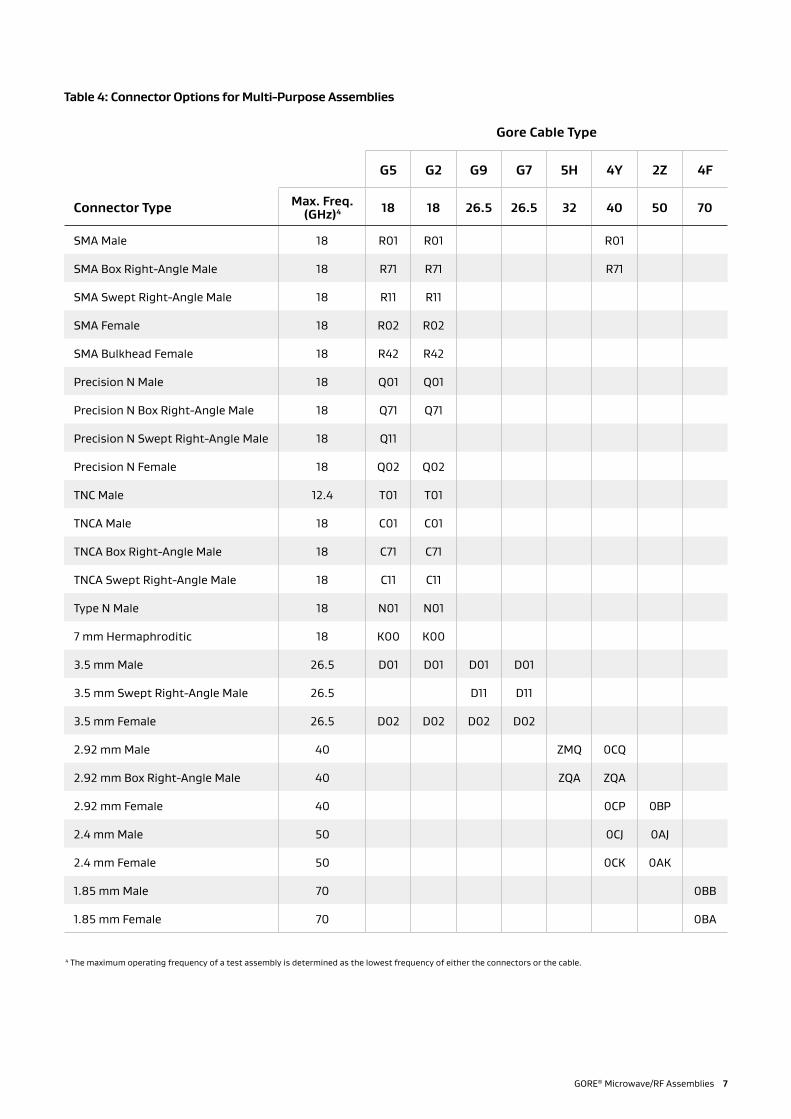
4 The maximum operating frequency of a test assembly is determined as the lowest frequency of either the connectors or the cable.
Table 4: Connector Options for Multi-Purpose Assemblies
Gore Cable Type
G5 G2 G9 G7 5H 4Y 2Z 4F
Connector Type Max. Freq. (GHz)4 18 18 26.5 26.5 32 40 50 70
SMA Male 18 R01 R01 R01
SMA Box Right-Angle Male 18 R71 R71 R71
SMA Swept Right-Angle Male 18 R11 R11
SMA Female 18 R02 R02
SMA Bulkhead Female 18 R42 R42
Precision N Male 18 Q01 Q01
Precision N Box Right-Angle Male 18 Q71 Q71
Precision N Swept Right-Angle Male 18 Q11
Precision N Female 18 Q02 Q02
TNC Male 12.4 T01 T01
TNCA Male 18 C01 C01
TNCA Box Right-Angle Male 18 C71 C71
TNCA Swept Right-Angle Male 18 C11 C11
Type N Male 18 N01 N01
7 mm Hermaphroditic 18 K00 K00
3.5 mm Male 26.5 D01 D01 D01 D01
3.5 mm Swept Right-Angle Male 26.5 D11 D11
3.5 mm Female 26.5 D02 D02 D02 D02
2.92 mm Male 40 ZMQ 0CQ
2.92 mm Box Right-Angle Male 40 ZQA ZQA
2.92 mm Female 40 0CP 0BP
2.4 mm Male 50 0CJ 0AJ
2.4 mm Female 50 0CK 0AK
1.85 mm Male 70 0BB
1.85 mm Female 70 0BA
GORE® Microwave/RF Assemblies 7

High Power/Low Loss Assemblies
Traditionally, applications that need high power/low loss assemblies must compromise on flexibility and size. Several highly flexible GORE® Microwave/RF Assemblies deliver low loss and high power-handling capability in a smaller package (Table 5). Delivering reliable performance up to 18 GHz (Figure 4), these assemblies have smaller diameters, making them more flexible and easier to handle. These cables are available with a variety of connectors (Table 6).
Figure 4: Typical Insertion Loss (dB) for High Power/Low Loss Assemblies5
5 The electrical specifications in this table are based on a 0.9 m (36 in) assembly length and maximum frequency with straight connectors.
6 The maximum operating frequency of a test assembly is determined as the lowest frequency of either the connectors or the cable.
Gore Cable Type G6 G3 8W
Maximum Frequency (GHz) 18 18 18
Typical VSWR 1.22:1 1.24:1 1.28:1
Typical Insertion Loss (dB) 0.80 1.00 0.75
Impedance (Nominal) (Ohms) 50
Attenuation at Maximum Frequency [dB/m (dB/ft)]
0.68 (0.21)
0.84 (0.26)
0.63 (0.19)
Typical Phase Stability (degree) +/- 8.0 +/- 6.0 +/- 15.0
Typical Amplitude Stability (dB) <+/- 0.05
Dielectric Constant (Nominal) 1.4
Velocity of Propagation (Nominal) (%) 85
Shielding Effectiveness (dB through 18GHz) > 100
Time Delay (Nominal) [ns/m (ns/ft)] 4 (1.22)
Table 6: Connector Options for High Power/Low Loss Assemblies
Gore Cable Type
G6 G3 8W
Connector Type Max. Freq. (GHz)6 18 18 18
SMA Male 18 R01 R01 R01
SMA Male (Vented) 18 ZN1 ZN1
SMA Box Right-Angle Male 18 R71 R71 R71
SMA Box Right-Angle Male (Vented) 18 ZSK
SMA Female 18 R02 R02 R02
SMA Bulkhead Female 18 R42 R42 R42
Precision N Male 18 Q01 Q01 Q01
TNC Male 12.4 T01 T01 T01
TNC Male (High Power, Vented) 5 ZLK
TNCA Male 18 C01 C01 C01
TNCA Box Right-Angle Male 18 C71 C71
TNCA Female 18 C02 C02 C02
Type N Male 18 N01 N01 N01
5 The electrical specifications in this table are based on a 0.9 m (36 in) assembly length and maximum frequency with straight connectors.
0.0
-0.2
-0.4
-0.6
-0.8
-1.0
-1.2 0 2 4 6 8 10 12 14 16 18 20
Inse
rtio
n lo
ss (d
B)
Frequency (GHz)
G6
G3
8W
8 GORE® Microwave/RF Assemblies
Table 5: High Power/Low Loss Assembly Specifications5
Electrical Properties
Mechanical/Environment Properties
Gore Cable Type G6 G3 8W
Center Conductor Solid Stranded Solid
Overall Diameter [mm (in)] 7.4 (0.290)
7.4 (0.290)
8.1 (0.320)
Nominal Weight [g/m (g/ft)]
124.6 (38)
118.1 (36)
144.3 (44)
Minimum Bend Radius [mm (in)]
38.1 (1.5)
38.1 (1.5)
50.8 (2.0)
Temperature Range (°C) -55 to 125

GORE® Microwave/RF Assemblies 9
Thermal Vacuum AssembliesGORE® Microwave/RF Assemblies are available for thermal vacumm (TVac) applications.
The cable and connector options listed in this data sheet are all available for TVac applications by configuring the part number with T/V at the end highlighted in table 7.
These assemblies will be manufactured using low outgassing materials having a TML of 1.0% or less and CVCM of 0.10% or less when tested per ASTM-595.
Integrity of critical hardware ▪ Gore’s focus on fitness for use ▪ Over 40 years of TVac applications experience
Successful test execution ▪ Repeatable and reliable products ▪ Broad range of thermal vacuum solutions proven over time
Ensure program schedule ▪ Access to Gore’s global experience and regional support
▪ Gore’s application engineering support will help you determine the right cable solutions
▪ Reduce risk of delays/test idle time for troubleshooting and addressing test anomalies
Save total cost ▪ Gore’s portfolio offers best total value with performance over time
▪ Solutions to fit testing budget ▪ Reduce risk of cost creep due to troubleshooting and replacement of faulty/unstable test equipment
Credit: NASAThermal-vacuum chamber

10 GORE® Microwave/RF Assemblies
Ordering Information
GORE® Microwave/RF Assemblies are identified by a 12-character part number that designates the cable type, connector types, and assembly length (Table 7):
Positions 1–2: The two-character identifier of the cable Positions 3–5 and 6–8: Connector codes A and B in alphanumeric order Positions 9–12: The length of the assembly expressed in inches to the nearest tenth, including zeroes to fill positions if the length is less than three digits Position 13: Identifier included only for an assembly that has been prepared for thermal vacuum chamber use.Example part number (positions 1–12): 4LS01S01010Example part number (positions 1–13): 4LS01S010120-T/V
7 Additional lengths available upon request
Table 7: Part Configuration for Ordering
Ordering Identifier (Part Number Positions)
Assembly Type Frequency(GHz)
Center Conductor
Cable Type (Pos 1-2)
Connectors(Pos 3-5 and 6-8)
Lengths7
(Pos 9-12)
Thermal Vacuum Identifier (Pos 13)
High-Density Interconnects (Table 1)
18 Solid 4L
See Table 2 012.0 12 in (0.30 m)
024.0 24 in (0.61 m)
036.0 36 in (0.91 m)
048.0 48 in (1.22 m)
060.0 60 in (1.52 m)
- T/V
18 Solid 53 - T/V
18 Stranded G1 - T/V
18 Solid G4 - T/V
40 Solid 54 - T/V
40 Solid 89 - T/V
70 Solid 55 - T/V
Multi-Purpose Assemblies(Table 3)
18 Solid G5
See Table 4
- T/V
18 Stranded G2 - T/V
26.5 Solid G9 - T/V
26.5 Stranded G7 - T/V
40 Solid 4Y - T/V
50 Solid 2Z - T/V
70 Solid 4F - T/V
High Power/Low Loss Assemblies (Table 5)
18 Solid G6
See Table 6
- T/V
18 Stranded G3 - T/V
18 Solid 8W - T/V
The GORE™ Microwave/RF Assembly Builder is a step-by-step tool that allows you to configure and request a quote for a test assembly with different connector options, assembly lengths, and frequencies. For more information, visit www.gore.com/rfcablebuilder.
The GORE™ Microwave/RF Assembly Calculator is an online tool that calculates and compares the insertion loss, VSWR, and other parameters for various cable types. For more information, visit tools.gore.com/gmcacalc.
1 2 3 4 5 6 7 8 9 10 11 12 13Cable Type Connector A Connector B Assembly Length -T/V

RF Jumper Assemblies up to 18 GHz
RF Jumper Assemblies provide a reliable solution for microwave interconnect applications that do not require traceability (Table 8). These 50 Ohm cable assemblies do not have serial numbers, but are 100-percent electrically verified to 18 GHz. They use low-profile SMA pins on both ends for compatibility with most standard systems. The SMA pin connector mates with SMA, 3.5 mm, and 2.92 mm socket connectors. These low-profile connectors allow easy access to system components, making them ideal for systems with multiple assemblies and limited space.
Table 8: Ordering Information
Length (in)
0.145 diameter 0.195 diameter
Gore Part Number
Minimum Typical
Insertion Loss (dB)
Gore Part Number
Minimum Typical
Insertion Loss (dB)
6 145-006.0 0.41 195-006.0 0.33
12 145-012.0 0.66 195-012.0 0.49
18 145-018.0 0.91 195-018.0 0.65
24 145-024.0 1.16 195-024.0 0.81
36 145-036.0 1.67 195-036.0 1.13
48 145-048.0 2.17 195-048.0 1.45
60 145-060.0 2.68 195-060.0 1.78
72 145-072.0 3.18 195-072.0 2.10
96 145-096.0 4.18 195-096.0 2.74
120 145-120.0 5.20 195-120.0 3.39
GORE® Microwave/RF Assemblies 11

W. L. Gore & Associates, Inc. 555 Paper Mill Road, Newark, DE 19711 UNITED STATES T +1 302 738 4880 F +1 302 738 7710 gore.com
NOTICE — USE RESTRICTIONS APPLY
Not for use in food, drug, cosmetic or medical device manufacturing, processing, or packaging operations.
GORE, Together, improving life, the purple cable and designs are trademarks of W. L. Gore & Associates. ©2020 W. L. Gore & Associates, Inc.
GM
CA-0
117-
R3-
DAT
-US-
JAN
20