good practice brochure on co/tri-generation · good practice brochure on co/tri- generation ......
TRANSCRIPT

Sanedi | 1
ENERGY INNOVATION FOR LIFE
GOOD PRACTICE BROCHURE ONCO/TRI-GENERATIONSTATUS QUO OF THE SOUTH AFRICAN MARKET
www.sanedi.org.za

ENERGY INNOVATION FOR LIFE Sanedi | 2
eneRGY innOVaTiOn FOR LiFe
ContentsIntroduction ........................
What is Cogeneration?......... ...
Technology .............................................................................. 6
Topping Cycle vs Bottoming Cycle ............................................ 6
Sizing Cogeneration ................................................................. 7
Heat Producing Plants with electricity as By-Product ............... 7
electricity Producing Plants with Heat as a By-Product ........... 7
Flexible Plants Meeting the demand of Heat andelectricity Consumers .............................................................. 7
electrical Load Matching ......................................................... 8
Thermal Load Matching ........................................................... 8
Cogeneration Systems.......... ....
Cogeneration Based on Steam Turbines ..................................11
Cogeneration Based on Gas Turbines ..................................... 13
Cogeneration Based on Combined Gas Turbine andSteam Turbine ....................................................................... 13
Cogeneration in Reciprocating internal Combustionengines ................................................................................. 13
Benefits of Cogeneration.......
Greenhouse Gas (GHG) emissions ................................. 15
dependency on electricity from the Grid ...................... 15
investments in electricity distribution networks .......... 15
Transmission Losses ...................................................... 15
Grid Capacity ................................................................15
Fuel Savings ................................................................ 15
eneRGY innOVaTiOn FOR LiFe
Sanedi | 3
ENERGY INNOVATION FOR LIFE
Performance ofCogeneration Systems..................Heat-to-Power Ratio ................................................... 18
Quality of Thermal energy ........................................... 18
Overall efficiency ........................................................ 18
Cogeneration Business Case .................... .....an example: Cogeneration with Gas engine ................. 19
annotation to Trigeneration ......................................... 20
Good Practice Examples .........
South african Case Studies ........................................... 24
German Case Studies ..................................................... 29
appendix ...............................
appendix a: Cogen Questionnaire ............................... 34
appendix B: abbreviations ........ ................................... 37
appendix C: Works Cited ............................................38
Sanedi | 4
ENERGY INNOVATION FOR LIFE
Good Practice Brochure onCo/Tri- GenerationStatus Quo for theSouth african MarketintroductionThe combined generation of heat and power in a generation facility can save more than 30% of primary energy and CO2 emissions. To date only a few Cogeneration plants have been constructed in South africa. information about these and their contribution to sustainable economics is scarce. This brochure aims to provide information on how a wide range of South african industries and companies can benefit by implementing Co/Tri-Generation strategies in their energy mix, thereby not only benefitting economically, but also significantly contributing to climate conservation. One of the main barriers to the widespread installation of Cogeneration plants is the perception of high start-up costs and the partly ambiguous or otherwise complex policy regulations regarding grid access, power purchase agreements and the claiming of carbon credits. an urgent need for further policy and regulatory frameworks exists to provide a conducive environment to enable the common use of Co/Tri-Generation. This area falls outside the scope of this guide. The good practice examples listed in this brochure prove that, even in the context of South africa’s current energy policy situation, considering the upgrade of existing boilers to Cogeneration plants or even the new build of Cogeneration systems can be economically and environmentally feasible. it needs to be emphasized that especially with a view to further policy support of Cogeneration, as a form of energy efficient energy generation, Co/Tri-Generation has the potential to contribute meaningfully to South africa´s energy policy objectives in terms of energy efficiency and climate protection. Cogeneration plants operate with significantly higher efficiencies and thus contribute positively to environmental requirements. Related to this, Cogeneration plants contribute significantly to saving of CO2 emissions. at the same time Cogeneration has the potential to strengthen companies’ power independence and competitiveness. The South african-German energy Programme (SaGen) which is funded by the German Government and implemented by the deutsche Gesellschaft für internationale Zusammenarbeit (GiZ) GmbH has identified a lack of know-how on Cogeneration as an energy efficient technology in South africa. as a result of this SaGen has supported the set up of a Facilitator for energy Service Companies (eSCo) and Cogeneration at the South african national energy development institute (Sanedi) to inform stakeholders on cogeneration technology and related policies, to establish networks, to carry out workshops and to develop this good practice brochure. The aim of this brochure is to gain a better understanding of Cogeneration in South africa and to highlight already existing good practices so that investments in one of the most promising energy efficiency technologies will increase.

Sanedi | 5
ENERGY INNOVATION FOR LIFE
1What isCogeneration?

ENERGY INNOVATION FOR LIFE Sanedi | 6
Absorption
chiller
Heat Chilled water
SupplyCHP heat
“Top up”heat
CHWFuel Electricity
CHP
Cooling
HVAC system
BoilersHeatload
TRIGENERATION
TechnologyCo/Tri-Generation is defined as the simultaneous production of more than one type of energy from a single fuel source. The production of heat and power at the same time is also known as Combined Heat and Power (CHP). When additionally producing cold next to electricity and heat, the process is called Trigeneration or Combined Cooling, Heat and Power (CCHP). Heating and cooling output may operate concurrently or alternately depending on need and system design. During the production of electrical or mechanical energy from a fuel, part of it is always lost in the form of thermal energy, called waste heat. Co/Tri-Generation processes the waste energy in form of thermal energy which is then used as process steam or steam for residential heating/cooling systems. In total, a higher percentage of the energy source (fuel) is used to generate energy on different quality levels (e.g. electricity, heat at a relatively low temperature for heating processes or heat at relatively high temperature for industrial processes).
When producing thermal energy and electrical and/or mechanical energy at the same time in one process the overall efficiency (η) of the process can be increased from about 40% - 60% up to 85% - 90%.
Topping cycle vs Bottoming Cycle Regarding the sequence of energy types generated, Cogeneration systems are characterized as topping or bottoming cycles. In a topping cycle, the fuel supplied is used to first produce power and then thermal energy, which is the by-product of the cycle and is used to satisfy process heat or other thermal requirements. Topping cycle Cogeneration is widely used and is the most popular method of Cogeneration, see Figure below:
Figure1: Trigeneration Cycle, Jonnathan McForlan
SEPARATE PRODUCTION OF ElECTRICITy AND HEAT
CogenerationSeparate Production of Electricity and Heat
Figure 2: efficiency Gains Through Cogeneration
Power Plant
Boiler
Fuel 100 Electricity 36
Heat 80Fuel 100
36 + 80ηseperate = =0,58200
CHIP PlantFuel 100Electricity 36
Heat 80
36 + 80ηseperate = =0,85200

Sanedi | 7
ENERGY INNOVATION FOR LIFE
In bottoming cycles in comparison, the primary energy production is thermal energy, while only the waste heat is used to generate power. Bottoming cycles are mainly used in industrial companies that require a large amount of process steam, e.g. cement and petrochemical industry. As the rejected waste heat still has a relatively high temperature after usage it can easily generate electricity in recovery boilers and/or turbines.
Sizing Cogeneration Cogeneration plants can range in size from as small as 1kW up to 1,000MW. The smallest plants, called micro-Cogeneration plants, are based on sterling motors. Used in domestic heating applications they have an electrical output of 1-3kW and a thermal output of approximately 20kW. Motor-operated Cogeneration plants range from 5kWel/30kWth up to 10MWel/10MWth. Here a variety of heat sources of piston engines are used including exhaust air recovery and motor oil waste heat. Gas turbine plants and combined-cycle plants offer a large number of alternatives for Cogeneration. Simple processes come with a gas turbine and a Heat Recovery Steam Generator (HRSG) see Figure 5 below:
TOPPING CyClE SySTEM
Figure 3: Topping Cycle System
Compressor
Combustor
Turbine
Supplemental Fuel
From feed water system Steam toProcess
Generator
BOTTOMING CyClE SySTEM
Figure 4: Bottoming Cycle System
Process
Fuel
Generator
To Stock
SteamTurbine
Waste heatRecoveryBoiler
Supplemental Fuel
From feed water system

Sanedi | 8
ENERGY INNOVATION FOR LIFE
More sophisticated systems comprise gas turbines, HRSG and the full variety of steam turbines available in the market. State of the art systems are 1,000MWel combined-cycle plants with 61% efficiency and fuel efficiency of up to 93%. For solid fuels the various boilers can come with the full set of steam turbines. Typical plants start at 1MW; large plants are 1,000MW super-critical units with heat extractions. Cogeneration plants can be divided into different groups:
Heat Producing Plants with electricity as By-Productin this instance the heat output of the plant is controlled and following demand of heat consumers. depending on the type of plant, electricity is produced proportional to the heat demand (Type 1) or electricity production is reduced or increased to follow varying heat demand (Type 2). Type 1 is typical for gas turbines with HRSG. Heat output is controlled by fuel input to the gas turbine. Electricity production is proportional to heat demand. Type 2 is typical for a condensing turbine in parallel to the heat consumers. Rising heat demand will reduce electricity production and vice versa.
electricity Producing Plants with Heat as a By-ProductUnder this scenario the electricity output is controlled and follows the electricity demand of the electric grid. Depending on the type of plant, heat is produced proportional to the electricity demand (equal to Type 1 above) or heat production is reduced or increased to follow electricity demand (Type 2). Type 2 is typical for an uncontrolled heat source, e.g. solar-thermal field or waste heat from a process, feeding a steam turbine with controlled heat extraction. At constant heat production, varying electricity demand will yield varying heat supply.
Flexible Plants Meeting the Demand of Heat and Electricity ConsumersThese systems need to be designed to consumer requirements. a typical plant comprises one or several steam boilers, often with different fuels capable of meeting steam and electricity demand. The steam boilers usually supply a steam header feeding a cascade of back-pressure steam turbines and condensing turbines. Heat and electricity demand will be met by changing heat production from the boilers utilizing steam storage properties of the steam headers. A special case is a single boiler with an extraction condensing type turbine. This indicates that the selection and operating scheme of a Cogeneration system is able to adjust to site-specific requirements. There are several factors which need to be considered, as described below:
Figure 5: Combined Cycle with HRSG, Flowserve industries
COMBINED CyClE PROCESS DIAGRAM
GeneratorGas Turbine
Superheater
Heat RecoverySteam Generator
High PressureSteam Drum
High Pressure Feedwater Pump
Low PressureSteam Drum
Deaerator
Superheater
Generator
Condenser
CondensatePump
Condenser Cooling Water Pump Cooling Tower
Main StreamStop Valve
Low PressureSteam High Pressure
Steam Turbine
High Pressure Steam Turbine
High PressureSteam
Stack
Economizer
Sanedi | 9
ENERGY INNOVATION FOR LIFE
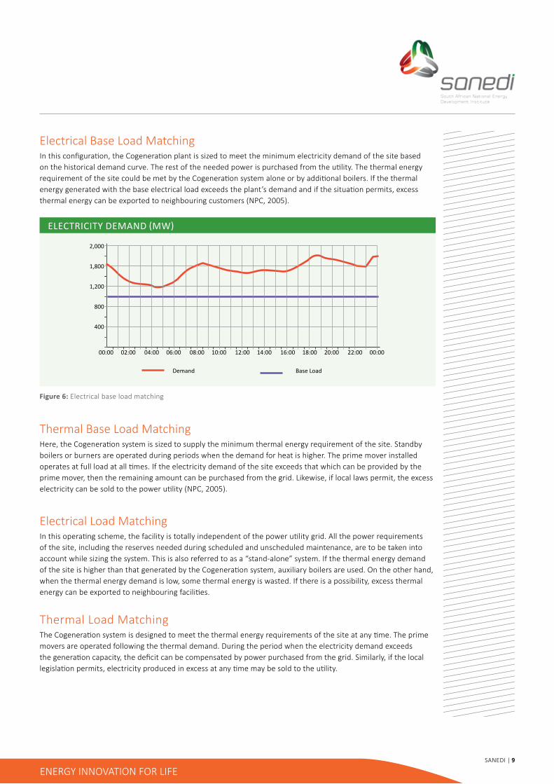
ElECtRICIty DEmanD (mW)
Figure 6: electrical base load matching
2,000
1,800
1,200
800
400
00:00 02:00 04:00 06:00 08:00 10:00 12:00 14:00 16:00 18:00 20:00 22:00 00:00
Demand Base Load
electrical Base Load MatchingIn this configuration, the Cogeneration plant is sized to meet the minimum electricity demand of the site based on the historical demand curve. The rest of the needed power is purchased from the utility. The thermal energy requirement of the site could be met by the Cogeneration system alone or by additional boilers. If the thermal energy generated with the base electrical load exceeds the plant’s demand and if the situation permits, excess thermal energy can be exported to neighbouring customers (nPC, 2005).
Thermal Base Load MatchingHere, the Cogeneration system is sized to supply the minimum thermal energy requirement of the site. Standby boilers or burners are operated during periods when the demand for heat is higher. The prime mover installed operates at full load at all times. If the electricity demand of the site exceeds that which can be provided by the prime mover, then the remaining amount can be purchased from the grid. Likewise, if local laws permit, the excess electricity can be sold to the power utility (NPC, 2005).
electrical Load MatchingIn this operating scheme, the facility is totally independent of the power utility grid. All the power requirements of the site, including the reserves needed during scheduled and unscheduled maintenance, are to be taken into account while sizing the system. This is also referred to as a “stand-alone” system. if the thermal energy demand of the site is higher than that generated by the Cogeneration system, auxiliary boilers are used. On the other hand, when the thermal energy demand is low, some thermal energy is wasted. if there is a possibility, excess thermal energy can be exported to neighbouring facilities.
Thermal Load MatchingThe Cogeneration system is designed to meet the thermal energy requirements of the site at any time. The prime movers are operated following the thermal demand. during the period when the electricity demand exceeds the generation capacity, the deficit can be compensated by power purchased from the grid. Similarly, if the local legislation permits, electricity produced in excess at any time may be sold to the utility.

Sanedi | 10
ENERGY INNOVATION FOR LIFE
Cogeneration Systems2

Sanedi | 11
ENERGY INNOVATION FOR LIFE
Co/Tri-Generation units can be based on steam turbines, gas turbines, combined cycle steam/gas turbines or reciprocating internal combustion engines. The most common way of producing electricity is using a Rankine cycle. in a Rankine cycle fuel is burned in a boiler to produce thermal energy and to heat up a working fluid (often water or gas). As the working fluid is pressurized it can take up more energy as it becomes “superheated”. When the superheated working fluid expands through a turbine, electrical power can be generated. in a regular power plant that produces solely electricity, the gaseous working fluid is condensed into a liquid after exiting the turbine and the Rankine cycle starts again. Only a certain part of the primary energy burned in the boiler can be converted into electricity. After exiting the turbine the working fluid is existent in a gaseous aggregate state, which implies that it still contains a lot of energy, saved in the form of thermal and chemical energy. The process of condensing the fuel e.g. in a cooling tower leads to immense losses of energy.
Cogeneration Based on Steam Turbines
The main benefit of using steam turbines for Combined Heat and Power production is that any fuel can be used. Steam turbines are very flexible because the steam that drives the turbine is produced in a typical industrial boiler which is easily modified to burn virtually any type of fuel, including waste fuels such as pulping liquor, landfill gas, forest residue and other biomass. Steam turbines are the only technology that can use energy from by-products like process heat from heat recovery boilers. The efficiency of steam turbines varies depending on how much heat compared to electricity is being produced and what technology is used for the extraction process. As CHP plants based on steam turbines have a relatively high heat to power ratio, they are mainly used at sites where the requirement for heat is higher than that of electricity.
There exist four different technologies of extracting steam for on-site usage of thermal energy:
Backpressure TurbineThe steam flows completely through the turbine and expands until it reaches the required steam pressure. During this expansion electricity is generated. Afterwards the whole amount of steam is used in the form of thermal energy at the required pressure.
BACK PRESSURE TURBINE
Figure 7: Back Pressure Steam Turbine, efficiency Guide for industry in asia
Boiler Turbine
Pump
Steam
Fuel
Process
Sanedi | 12
ENERGY INNOVATION FOR LIFE
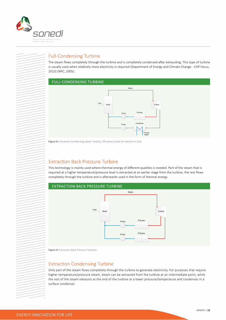
Full-Condensing TurbineThe steam flows completely through the turbine and is completely condensed after exhausting. This type of turbine is usually used when relatively more electricity is required (Department of Energy and Climate Change - CHP Focus, 2013) (nPC, 2005).
Full-ConDEnSIng tuRBInE
ExTRACTION BACK PRESSURE TURBINE
Extraction Back Pressure TurbineThis technology is mainly used where thermal energy of different qualities is needed. Part of the steam that is required at a higher temperature/pressure level is extracted at an earlier stage from the turbine, the rest flows completely through the turbine and is afterwards used in the form of thermal energy.
Extraction Condensing TurbineOnly part of the steam flows completely through the turbine to generate electricity. For purposes that require higher temperature/pressure steam, steam can be extracted from the turbine at an intermediate point, while the rest of the steam exhausts at the end of the turbine at a lower pressure/temperature and condenses in a surface condenser.
Figure 8: extraction Condensing Steam Turbine, efficiency Guide for industry in asia
Figure 9: extraction Back Pressure Turbines
Boiler Turbine
CondenserPump
Steam
CoolingWater
Fuel
Pump Process
Boiler Turbine
Pump
Steam
Fuel
Pump Process
Process

Sanedi | 13
ENERGY INNOVATION FOR LIFE
Boiler Turbine
CondenserPump
Steam
CoolingWater
Fuel
Pump Process
Cogeneration Based on Gas TurbinesGas turbines are usually fed with natural gas that is burned in a pressurized combustion chamber. The energy fuel serves at the same time as the working fluid. In gas turbines the exhaust gases have a temperature between 400°C and 550°C and can be used to heat water or as process steam by using the gases in a heat recovery boiler. in the boiler thermal energy embodied in the exhaust gas is transferred to water via heat exchangers. The main advantage compared to steam turbines is that gas turbines can be used in intermittent operation (NPC, 2005).
Cogeneration Based on Combined Gas Turbine & Steam TurbineThe benefit of combining a steam cycle with a gas cycle is that more power can be produced compared to the single cycle solution. The exiting gas of the gas turbine is used in a recovery boiler to heat up water and generate steam. Afterwards the steam is fed into a steam turbine and additional power is produced. The exhaust gas of the steam turbine can then be used for meeting the thermal energy requirements (NPC, 2005) (Department of Energy & Climate Change - CHP Focus, 2013).
Cogeneration in Reciprocating Internal Combustion EnginesAs combined cycle solutions, reciprocating internal combustion engines also have a high electricity output. Heat can be recovered from exhaust gas or the engine’s cooling water. The recovered heat is usually of low power, i.e. low-pressure steam or hot water. Reciprocating engines are usually used at smaller sites with a higher demand for electricity than thermal energy. As gas turbine systems, reciprocating engine systems can also operate
intermittently (NPC, 2005) (Department of Energy & Climate Change - CHP Focus, 2013).
ExTRACTION CONDENSING STEAM TURBINE
RECIPROCATING ENGINE COGENERATION SySTEM
Figure 10: extraction Condensing Steam Turbine
Figure 11: Reciprocating Engine Cogeneration System, UNES-CAP
Pump
Steam orHot Water
Fuel
Process
Oil Air Water
ExhaustHeat
ReciprocatingEngine
Coolers
~ 200°C
~ 450°C

Sanedi | 14
ENERGY INNOVATION FOR LIFE
Benefits ofCogeneration3
Sanedi | 15
ENERGY INNOVATION FOR LIFE
Apart from the improvement of the industrial efficiency there are various additional reasons for the on-site installation of Co/Tri-Generation plants:
Greenhouse Gas (GHG) emissionsOn-site Co/Tri-Generation plants or captive power plants displace grid electricity. Eskom is part of the Southern African Power Pool (SAPP), whose electricity is mainly generated in coal power plants. Therefore Co/Tri-Generation can make a big contribution in reducing GHG emissions as less NOx, CO2 and particulate emissions that are emitted.
dependency on electricity From the GridThe impact of electricity prices on a company´s operational cost can be reduced or even elimated through the implementation of Cogeneration strategies. On-site generation of electricity reduces the dependency on electricity from the national grid. The extent of the reduction in operational costs depends on the type and configuration of the process plant, the type and amount of by-product and/or waste heat available for power generation. On-site Co/Tri-Generation plants can reduce the impact of power shortages from the national grid in connecting essential equipment to the own electricity production with back-up from the grid.
Investments in Electricity Distribution NetworksWhen using Cogeneration on-site, investment costs in the electricity network can be reduced and even isolated areas can be supplied with electricity.
Transmission LossesIn South Africa electric power transmission and distribution losses were about 10% of the total power output between 2008 and 2012. Transmission losses can be reduced as Cogeneration plants are usually placed close to the place of consumption.
Grid CapacityIn the case of a feed-in into the national electricity grid, the capacity of the grid can be increased in the short run and the process is faster than the building of new power plants. eskom is supplying about 95% of South africa’s total electricity demand. according to the annual report 2013 eskom’s total nominal capacity was 41.919 GW while the peak demand was 35.25 GW with further rises expected. an increase of South africa´s grid capacity will help lower the risk of power shortages.
Fuel SavingsAs Cogeneration increases the overall efficiency of heat and power production, there is less fuel input that is needed to produce a certain amount of energy as compared to the separate generation. The benefits of fuel savings will be described in the example below:
in the baseline, electricity (24 units required) and heat (34 units required) is generated separately. The fuel input when applying an efficiency of 40% for a power station and 85% for the heating boiler is 100 units in total (60 for power, 40 for heat). When applying Cogeneration instead, the fuel input can be reduced to 68 units, when applying efficiencyof 85% to the CHP plant it leads to reduced losses of 10 compared to 42 units thereby improving fuel useefficiency by more than 30 %, refer to Figure 12 on the next page (European Commision, 2002) (The World Bank)(PretorVG, 2012) (Böhmer, 2012).

Sanedi | 16
ENERGY INNOVATION FOR LIFE
ENERGy USE EFFICIENCy By COGENERATION
These benefits translate into project economics depending primarily on the load patterns and design of the Co/Tri-Generation plant. The plant design should maximise the hours of use of these capital intensive investments.
Figure 12: Improvement in Energy Use Efficiency by Cogeneration, GIZ training manual
Power station 6040% efficiency
Heating boiler 4085% efficiency
CHP plant85% efficiency
Fuel = 68
Electricity 24
Electricity 24
Heat 34
Heat 34
Loss 42
Loss 10

Sanedi | 17
ENERGY INNOVATION FOR LIFE
4Performance ofCogeneration
Systems

Sanedi | 18
ENERGY INNOVATION FOR LIFE
Heat-to-Power RatioHeat-to-power ratio is one of the most important technical parameters influencing the selection of the type of Cogeneration system. The heat-to-power ratio of a facility should match with the characteristics of the Cogeneration system to be installed. Heat-to-power ratio is defined as the ratio of thermal energy to electricity required by the energy consuming facility. Though it can be expressed in different units such as Btu/kWh, kcal/kWh, lb./hr/kW, etc., here it is presented on the basis of the same energy unit (kW). Basic heat-to-power ratios of the different Cogeneration systems are shown in table below along with some technical parameters. The steam turbine Cogeneration system can offer a large range of heat-to-power ratios (nPC, 2005).
HEAT TO POWER RATIOS FOR DIFFERENT COGENERATION SySTEMS
Cogeneration system Heat-to-power ratio (kWth/kWe)
Power output (% of fuel input)
overall efficiency(%)
Back-pressure steam turbine 4.0 - 14.3 14 - 28 84 - 92
Extraction-condensing steam turbine
2.0 - 10.0 22 - 40 60 - 80
Gas turbine 1.3 - 2.0 24 - 35 70 - 85
Combined cycle 1.0 - 1.7 34 - 40 69 - 83
Reciprocating engine 1.1 - 2.5 33 - 53 75 - 85
Quality of Thermal energyIn addition to the quantities of power and heat demanded, the required quality of thermal energy, i.e. temperature and pressure, is an important aspect influencing the decision between different Cogeneration system options. The required quality determines whether a bottoming or a topping cycle is more suitable. For a sugar mill needing thermal energy at about 120°C, a topping cycle Cogeneration system can meet the heat demand. On the other hand, for a cement plant requiring thermal energy at about 1,450°C, a bottoming cycle Cogeneration system can meet both high quality thermal energy and electricity demands of the plant (nPC, 2005).
Overall EfficiencyThe overall efficiency of Cogeneration systems is the total amount of net useful electricity and thermal heat output relative to the total fuel input (NPC, 2005). It is often used to determine the performance of Cogeneration systems. This performance indicator does not distinguish between thermal energy and electricity, although the quality of these types of energy differs.
Table 1: Heat to Power Ratios for different Cogeneration Systems

Sanedi | 19
ENERGY INNOVATION FOR LIFE
5CogenerationBusiness Case

Sanedi | 20
ENERGY INNOVATION FOR LIFE
ENERGy SUPPly CONTRACTING
The optimal way to consider the business case for Cogeneration is to take into account all costs and all benefits over the entire lifetime of the project. For a Cogeneration project the following needs to be considered:
• The capital costs of the Cogeneration unit and corresponding equipment,
• The costs of operation and maintenance (O&M) of the system,
• The benefits associated with the project, including the savings achieved in comparison to an existing or an alternative heat and power supply,
• Other benefits, such as incentives and carbon credits for Cogeneration (if available and applicable).
apart from the option of owning and operating their own Cogeneration plant, companies can also consider partnering with 3rd parties, for example, energy Service Companies (eSCos) through models such as energy Supply Contracting (eSC). The main participants involved in an eSC arrangement are the eSCo, the customer and a financing institution. The eSCo supplies the customer or the tenant directly with use energy such as heating, cooling, light, electricity, steam or compressed air and charges the customer for the quantity (e.g. in kWh). For this purpose, the eSCo converts primary energy (e.g. gas received from a gas supplier) into the specifically required use energy, doing this directly on the basis of customer use of pre-installed decentralised energy supply systems (e.g. a small-scale Cogeneration unit). The eSCo owns the plant and will be responsible for acquiring the necessary funding to construct, operate and maintain the plant.
An Example: Cogeneration with Gas EngineFor an implementation of a Cogeneration process in a facility the electrical and heat/cooling demand (hot water, process steam, cooling) should be evenly spread over the year. a heat/cooling base demand of approx. 4,000 - 6,000 h per year is necessary or ideal for an economic application. The easiest way to define the heat/cooling capacity of the Cogeneration unit is to plot the annual load duration curve and determine the heat/cooling demand at the desired operation hours. The base heat/cooling demand is supplied by the new Cogeneration unit at full load operation.Depending on the heat capacity chosen, a gas engine or micro turbine can be selected. Due to the fixed ratio between electrical capacity and heat capacity the installed electrical power is set. in general, the electricity generated at full load operation is completely consumed internally by the facility at any time. in appendix a there is an example for a start up questionnaire that facilitates the required data collection to enable the economic calculation. an economic calculation will be performed for the defined Cogeneration unit with the following steps included:
Figure 13: Schematic of energy Supply Contracting
BankSecurity (e.g surety, land charge)
Financing
Provides heat/electricity
Payment for servicesrendered Heat/electricity cost
Pass-through
Client
Tenant
Contractor/ESCo

Sanedi | 21
ENERGY INNOVATION FOR LIFE
STATIC AMORTIzATION CAlCUlATION
• determination of revenues based on the amounts of electricity and heat respectively saved, multiplied by the prices of electricity and heat fuel
• determination of capital expenditure based on specific investment costs per kW installed electrical power,
• determination of debt service considering different financing sources, interest rates and loan maturities,
• determination of operation and maintenance costs, considering:
͵ Personnel (fixed),
͵ insurance (fixed),
͵ Maintenance (fixed and variable), and
͵ Fuel costs (variable).
• The fuel costs are calculated equivalent to the revenues and is based on the consumed fuel to operate the Cogeneration unit multiplied by the price of fuel.
• determination of net income and cash flow based on the results of the previous steps and income tax.
• determination of economical key indicators like amortization and internal rate of return (iRR). The iRR can be calculated for equity and total capital (project iRR).
The following example illustrates the aspects highlighted above with an investment of R10,2m and earnings before interest, taxes and depreciation of R3.9m; design electric output of 637 kW, design heat output of 766 kW at an electric and gas price of 203 ct/kWh and 41 ct/kWh (HHV) respectively.
Figure 14: Static amortization Calculation (electricity price: 203 ct/kWh; gas price: 41 ct/kWh (HHV))
Annotation to TrigenerationCooling demand can be partly supplied by an absorption chiller, which leads to an additional heat demand. as a consequence of this, a bigger Cogeneration unit can be selected. To check whether this is economical, a separate evaluation is necessary comparing energy concepts including compression and absorption chillers.
40
35
30
25
20
15
10
5
00 2 4 6 8 10
Investment
ebItd
Amortization
electricity: 637 kWHeating: 766 kWOperation: 5000 h/a
time in years
Inve
stm
ent/
Earn
ings
in m
illio
n ZA
R

Sanedi | 22
ENERGY INNOVATION FOR LIFE
Full-Condensing turbine
good Practice Examples6

Sanedi | 23
ENERGY INNOVATION FOR LIFE
South african Case StudiesBiomass Cogeneration Jan Kempdorp Nothern Cape: 100 kW
General InformationThe construction for the Biomass Cogeneration Plant for the Abattoir Jan Kempdorp has been completed in November 2012. After successful commissioning it started to produce power and heat in December of the same year. Initially there were challenges with formation of crusts in the digester which negatively impacted the operation. After a period of continuous optimization this problem is now under control and the plant produces biogas of good quality with Methane (CH4) content beyond 55%.
The plant is highly automated. The process steps shredding, mixing and fermentation are running fully automated. iBert did design the Biomass Cogeneration Plant, was responsible for the construction of it and is now responsible for Operation & Maintenance.

Sanedi | 24
ENERGY INNOVATION FOR LIFE
TechnologyThe iBERT600 Plant runs exclusively on the bio waste generated at the abattoir where it is situated, the system runs on the waste streams produced at the abattoir (Bovine Blood, Bovine Stomage Content, Bovine Slaughter Waste, dung).
The system has allowed the abattoir to generate much needed cheap energy from previously costly wastes. In the past the abattoir had a rather high waste management cost for removal of wastes and energy intensive processing of the blood with the iBERT Reactor. Consequently, the abattoir now generates savings of about R60,000 of waste costs and R45,000 of diesel per month and has very high degree of energy independence which provides a safeguard against unplanned power blackouts. These blackouts do not affect the business and operations of the abattoir anymore and gives this business a definite edge in the market place.
ElECTRICITy Internal Combustion Engines (MAN) 115 kWel
ηel 37.5 %
ηoverall 84.6 %
Fuel consumption (Abattoir waste) 45,500 m3/year
Methane 195,000 m3/year
electricity consumed 639 MWh/year
COOlINGn/a
HEATINGHot water supply
ENERGy SAvINGSGrid electricity displaced 247 MWh/year
Replaced diesel heating 991 MWh/year
EMISSIONSAnnual reductions 2,000 t CO2-equ
CONTACT | Name: ishkus Bio 4 Gas | Email: [email protected]
Table 2: Jan Kempdorp Nothern Cape Energy Data

Sanedi | 25
ENERGY INNOVATION FOR LIFE
Gas Turbine Tri-generation at MTN, JohannesburgGeneral informationin the West Rand of Johannesburg, the multinational communications company MTn runs an off grid Trigeneration plant together with City of Joburg. it is located at MTn´s head-office and produces electricity, heat and chilled water at the same time to partially meet MTn´s energy requirements. Construction of the plant started in October 2008 and in 2012 the Trigeneration plant was registered as a carbon credit project under the United Nation’s Clean Development Mechanism Programme. The French energy company EDF bought all carbon credits the plant will earn over ten years.
MTn´s building complex consists of offices, data centres and telecommunication switch facilities. Before the installation of the on-site Trigeneration plant, the commercial site was provided with electricity from City of Joburg through the national grid, heat from conventional electric heaters and cooling was provided through conventional electric vapour compression chillers.
The 2MW Trigeneration plant will be supplemented by the already existing cooling and heating systems and the national electricity grid to fully meet the energy demand of MTN. The fuel used by the plant is methane-rich natural gas from the Temane gas field in Mozambique and is supplied via Sasol´s pipeline to Egoli Gas in Johannesburg.
TechnologyFor the generation of electricity that is used in MTN´s data and switching centres, the off-grid plant burns natural gas in two internal combustion engines. The waste heat flow from the engines is led through heat exchangers to transfer lost thermal energy to water. For the cooling of the electronic equipment and for the air-conditioning in the offices, three Lithium bromide absorption chillers are used, to convert the hot water to chilled water that can be used in the air-handling units. For heating needs a second heat exchanger is in usage. Both, the cooling and the heating are controlled automatically. The wastewater from the heating and cooling processes is first cooled down in the cooling tower and then it is deployed in the bathroom facilities of the office-complex.

Sanedi | 26
ENERGY INNOVATION FOR LIFE
ElECTRICITy2 internal combustion engines (spark ignition) Ge Jenbacher austria (J320 gas-powered)
1,063 1,200
kWel
kWth each
ηel ≈ 35 %
Fuel consumption 4945.16 m3/year
electricity consumed internally 18,623 GWh/year
COOlINGAbsorption chiller 1 & 2 (by Carrier) 550 kW
Absorption chiller 3 (by Carrier) 450 kW
Refrigerant Lithium bromide (ZERO global warming potential)
HEATINGHeat exchanger 100 kW
ENERGy SAvINGSTotal ≈ 26 GWh/year
Grid electricity displaced 18.6 GWh/year
Replaced electricity cooling 5.4 GWh/year
Replaced electricity heating 876 MWh/year
EMISSIONSAnnual reductions 2,000 t CO2-equ
Table 3: MTn’s energy data

Sanedi | 27
ENERGY INNOVATION FOR LIFE
Capital expenditureThe investment costs for the Trigeneration plant were R50 million ZAR. Incorporating an electricity price increase the anticipated payback period of the project is less than 5 years. For the future MTN is even planning to extend the project. An additional data centre is going to be built in Centurion between Pretoria and Johannesburg that shall compliment the electricity grid. For that reason a 4MW gas-power plant is planned at these sites.
CONTACT | Name: Willem Weber | Email: [email protected]
Cogeneration from Natural Gas at Sasol Synfuels LtdGeneral InformationSasol is an international energy and chemical company based in Johannesburg, South africa and the world´s biggest producer of synthetic fuels from coal and gas (CTL and GTL). One of Sasol’s subsidiaries, Sasol Synfuels, located near Secunda, Mpumalanga, uses coal for 95% of its feedstock to synthesise fuels and chemicals through the High Temperature Fischer Tropsch process. This energy intensive process purchases typically 50 to 70% of its electricity from the national electricity grid (eskom), with the rest being internally generated from onsite 17 x 540t/h coal fired steam boilers and 10 x 60MW steam turbine generators.
In 2010 Sasol Synfuels installed two gas turbine generators running on natural gas to substitute some of the electricity supplied from the national grid. The natural gas is supplied from the Sasol Mozambique pipeline. Two years later, in 2012, two heat recovery steam generators were installed to recover the waste heat from the gas turbines.
The project forms part of eskom’s Medium Term Power Purchase Programme (MTPPP) process and the Power Purchase agreement will expire at the end of March 2014.
TechnologyThe core business of Sasol Synfuels is the production of liquid fuels and chemicals, not power generation. Therefore steam generated in the boilers is primarily for process purposes, and surplus steam, after process requirements have been met, is available for power generation. Growth in process steam demand over the years resulted in significant idle capacity on the steam turbine generators.
The two gas turbine generators generate 200MW electricity from natural gas as feedstock, while the exhaust gas from the gas turbines is captured and fed into two heat recovery steam generators (HRSGs). The HRSG steam is not used in a dedicated steam turbine generator (as is normally the case), but routed to the existing steam turbine generators where under-utilised capacity exists. in total, the effective capacity of the combined gas and steam cycle is 268MW.
ElECTRICITyTwo gas turbine generators, Ge PG9171 (e) 100 MWel each
Operating Capacity 140 MW
Steam turbine generators (unused capacity) from 10 x 60MW existing plants)
68 MW
Effective capacity 268 MW
Gas supply 2,200 GJ/hour
HEATINGTwo heat recovery steam generators 145 t/h each (40 bar)
Exhaust flow gas turbine 1,200 t/h per turbine
EMISSIONSAnnual average reductions ≈1,051,316 t CO2-equ
Table 4: Sasol Synfuel energy data
Sanedi | 28
ENERGY INNOVATION FOR LIFE
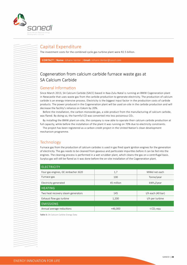
Capital expenditureThe investment costs for the combined cycle gas turbine plant were R2.5 billion.
CONTACT | Name: Johann Venter | Email: [email protected]
Cogeneration from calcium carbide furnace waste gas atSa Calcium Carbide
General InformationSince March 2013, SA Calcium Carbide (SACC) based in Kwa-Zulu-Natal is running an 8MW Cogeneration plant in newcastle that uses waste gas from the carbide production to generate electricity. The production of calcium carbide is an energy-intensive process. electricity is the biggest input factor in the production costs of carbide products. The power produced in the Cogeneration plant will be used on-site in the carbide production and will decrease the facility’s reliance on eskom by 20%. Before the installation, the carbon monoxide gas, a side-product from the manufacturing of calcium carbide, was flared. By doing so, the harmful CO was converted into less poisonous CO2.
By installing the 8MW plant on-site, the company is now able to operate their calcium carbide production at full capacity, while before the installation of the plant it was running on 70% due to electricity constraints. The project has been registered as a carbon credit project in the United Nation’s clean development mechanism programme.
TechnologyFurnace gas from the production of calcium carbides is used in gas fired spark ignition engines for the generation of electricity. The gas needs to be cleaned from gaseous and particulate impurities before it can be fed into the engines. The cleaning process is performed in a wet scrubber plant, which cleans the gas on a centrifugal basis. Surplus gas will still be flared as it was done before the on-site installation of the Cogeneration plant.
ElECTRICITyFour gas engines, Ge Jenbacher J620 1,7 MWel net each
Furnace gas 100 Tonne/year
electricity generated 45 million kWhel/year
HEATINGTwo heat recovery steam generators 145 t/h each (40 bar)
Exhaust flow gas turbine 1,200 t/h per turbine
EMISSIONSAnnual average reductions ≈46,000 t CO2-equ
Table 5: Sa Calcium Carbite energy data

Sanedi | 29
ENERGY INNOVATION FOR LIFE
CONTACT | Name: Mike Rycroft | Email: [email protected]
Capital expenditureThe investment costs for the project is R115 million that is sourced from the idC (industrial development Corporation). The loan was partly provided by the Green Energy Efficiency Fund (GEEF), supported by the German Development Bank (KfW). SACC calculated a pay-back period of 3.2 years, including the electricity cost savings from grid supply. The revenues from the carbon credits will be used to repay the loan. The yearly O&M costs are estimated to be R10.3 million. The main reason for the project was a measure to reduce the impact of increasing electricity prices. in total the electricity bill of the company could be cut down by about 20%.
German Good PracticeEnergy Saving Partnership LVR- Klinik Bonn
General informationProject History:
1996/97: design of the energy Saving Program
Closure of framework agreement between LVR – Clinic and imtech
1998: Start of construction phase
Realization of energy efficiency measures
Installations during the normal operations of the clinic
1999: Start of operations and energy supply by Imtech
Since 2000: Successive refurbishment of the clinic
2010: Extension of the energy service contract until 2020
2011: Reinvestment in CHP and Building Management System (BMS)
Project Partners: LVK- Kinik Bonn, Energy Agency North Rhine Westphalia- Consultant, Imtech Contracting- energy Service Company (eSCo)
Target of the energy Saving Program• development of an energy Saving Program for Heat and steam supply
• Power supply
• Ventilation and aircondition
• Objectives of the realization
• Reduction of costs and energy consumption
• Protection of the environment
Technology• 21MW high-pressure steam boiler system
• Heat and steam supply via steam distributor network
• Power supply from the puplic grid
• 1.9MW absorption chiller
• 320,000 m³/h HVaC systems
• 45 GWh/a primary energy consumption
• 9,400 t/a CO2 emissions

Sanedi | 30
ENERGY INNOVATION FOR LIFE
Implementation of the energy saving program measures:
• Conversion of the heat supply from inefficient high-pressure steam to warm water
• Establishment of a new energy centre located near the clinic’s main energy consumption areas
• Highly efficient energy production by means of power, heat and refrigeration coupling
• Reduction of the installed heat output from 21MW to 10MW
• Partial modernization of the ventilation and air-conditioning systems
• Building Management System, energy controlling
RESultS - REDuCtIon oF Co2 EMISSIONS
RESultS - CoSt REDuCtIon
Figure 18: Reduction of CO2 emisions From Facility
Figure 19: Cost reduction from facility, LVK- Klinik
12.000
10.000
8.000
6.000
4.000
2.000
098 99 00 01 02 03 04 05 06 07 08 09 10 11 12
Reduction > 50%or > 4,600 to/a
100 2
/a
120%
100%
80%
60%
40%
20%
0%98 00 01 02 03 04 05 06 07 08 09 10 11 12
Energy and O&M costsRefinancing costs

Sanedi | 31
ENERGY INNOVATION FOR LIFE
ElECTRICITyηel 36 %
ηoverall 92 %
Fuel consumption (Abbotoir waste) 1,275,000 m3/year
electricity consumed internally 20 MWh/year
HEATINGHeat exchanger 1,040 kW
ENERGy SAvINGSTotal 4.5 GWh/year
Grid electricity displaced 3,900 MWh/year
Replaced electricity cooling 6,000 MWh/year
Replaced electricity heating 300 MWh/year
COOlINGAbsorption chiller 1,000 kW
Refrigerant -
EMISSIONSAnnual reductions 1,400 t CO2-equ
*compared to separate production of heat and electricity. German electricity mix 601g CO2/kWhel
Table 6: LVK-Klinik energy data
CONTACT | Name: Till Tomann, imtech | Email: [email protected]
Heideblume dairy in elsdorf-Rotenburg
General information• Project duration: January 2006 until December 2015
• Steam, iced water, space cooling, compressed air and drinking water
• Final energy consumption before: 2.9MWh/year after: 2.2MWh/year
• energy saving of 19%
• CO2-emission 2009 reduced by over 3,700 t
• Staff of 6 => energy delivery 365 days a year, 24 hours a day
• extension of contract for 15 years, 5 years before end of contract (november 2010)
• In 2011 construction and operation of a new power plant
CHCP: electricity, steam and cooling - high technology absorption chiller
• Innovative solutions in cooperation ESCo/client
• Reduction of 5,000 t CO2/year (appr. 60%)

Sanedi | 32
ENERGY INNOVATION FOR LIFE
TechnologyEnergy efficiency measures:
• Optimization of boiler operation by switching to multi-boiler regulation and control
• Use of the heat energy of the hot gas for the ammonia feed water
• improved performance (COP) of the ice water and the space cooling system
• Use of efficient piston compressor chiller for optimized control load
• Speed control of the fan of the wastewater treatment plant
• demand control of the compressed air system
EnERgy SavIng 19%Reduction of energy consumption 12.6 GWh/a
C02 reduction 3,623 t/a
Reduction of energy cost 500,910 €/a
investment 600,000 €/a
Return on equity in first year 83%
www.pgn-architekten.de
Figure 21: energy Savings

Sanedi | 33
ENERGY INNOVATION FOR LIFE
CONTACT | Name: Thomas Müller, Heideblume Molkerei, | Email: [email protected]
Figure 22: indicators of energy Optimisation
INDICATORS OF ENERGy OPTIMISATION
Before opti misati on Aft er opti misati on
4,2
4,1
4,0
3,9
3,8
3,7
3,6
Energy costsmill. €/a
4,2 0,5
3,7
70
65
60
55
50
45
40
Energy consumpti onGWh/a
65,4 12,6
52,8
26
25
24
23
22
21
20
CO2 reducti onTsd. t/a
25,9 3,6
22,3
Saving
Sanedi | 34
ENERGY INNOVATION FOR LIFE
Appendix A: Cogen Questionnaire
1. General and Contact Information
date: .......................................................................................................................................................................................
Company name: .......................................................................................................................................................................
Business sector: ......................................................................................................................................................................
Main Products: .......................................................................................................................................................................
Staff, ca.: ..................................................................................................................................................................................
Revenues in million ZaR: ........................................................................................................................................................
notes: ......................................................................................................................................................................................
address: ..................................................................................................................................................................................
Contact Person: ............................................................................................. Tel: ..................................................................
Position: .....................................................................................................Mobile:.................................................................
Fax:.............................................. email: .................................................................................................................................
2. Operational Information
Operating hours per day :.......................................................................................................................................................
Operating days per week :.....................................................................................................................................................
Operating weeks per year :...................................................................................................................................................
Operating hours per year :.....................................................................................................................................................
Operation time:
regular Monday :....................................................... o’clock until Friday :........................................... o’clock
extra .......................................................................o’clock .............................................................. o’clock
Appendices7

ENERGY INNOVATION FOR LIFE Sanedi | 35
3. General Questions yES NO to ClARIFy until (date)
3.1 Do you have an energy management system? If yes, which one?............................................................ ........................................................................................
3.2 does documentation exist about energy systems/components?
3.3 Are single consumer measured? If yes, how many?............................................................ ........................................................................................
3.4 Are monthly values available for electric consumption?
3.5 are hourly values/load curves available for electric consumption?
3.6 Are monthly values available for heat consumption?
3.7 are hourly values/load curves available for heat consumption?
3.8 Are monthly values available for chill consumption?
3.9 are hourly values/load curves available for chill consumption?
3.10 Is a chill storage installed?
3.11 Is a heat storage installed?
3.12 Were efficiency activities conducted in the last years?
If yes, which? ..................................................................
........................................................................................
3.13 Which different energy consuming processes are established?
3.13.1 Process 1:...................................................................
....................................................................................
Which hot water temperature is needed?
Which cold water temperature is needed?
Which process steam conditions (pressure/temperature)are needed?
Process 2: ............................................................................
.............................................................................................
3.13.2 Which hot water temperature is needed?
Which cold water temperature is needed?
Which process steam conditions (pressure/temperature) are needed?
°C ..............................................................................................
°C ..............................................................................................
bar°C ..............................................................................................
°C ..............................................................................................
°C ..............................................................................................
bar°C ..............................................................................................
3.14 Planned investments (changes) in energy efficiency and energy supply system: ...................................................................
........................................................................................................................................................................................................
........................................................................................................................................................................................................
........................................................................................................................................................................................................
........................................................................................................................................................................................................
...................................
...................................
...................................
...................................
...................................
...................................
...................................
...................................
...................................
...................................
...................................
...................................
...................................

ENERGY INNOVATION FOR LIFE
4. e
neR
GY
iMPO
RT
Yea
R:
En
ergy
Sou
rce
Amou
ntEn
ergy
con
tent
Ener
gyPe
ak D
eman
dEn
ergy
Cos
tsN
otes
--
(1)
MW
h/a
kW; t
/h; l
/h; n
m3/
hZa
R/a
-
1el
ectr
icity
MW
h/a
-
2n
atur
al G
asM
Wh(
HH
V)/a
3LP
Gl/a
4Li
ght f
uel o
ill/a
5H
eavy
fuel
oil
t/a
6H
ard
coal
t/a
7Li
gnite
t/a
8Pr
oces
s st
eam
t/a
9D
istr
ict h
eatin
gM
Wh/
a-
10H
ot w
ater
MW
h/a
-
11Co
ld w
ater
MW
h/a
-
12 13 14 15
5. E
NER
Gy
PRO
DU
CTI
ON
Ener
gy S
ourc
eAm
ount
Ener
gy C
onte
ntEn
ergy
Peak
Dem
and
Not
es
--
1)M
Wh/
akW
; t/h
; l/h
; nm
3/h
-
1M
Wh/
a
2t/
a
3M
Wh/
a
4M
Wh/
a
5M
Wh/
a
6 7 8 9 6. C
omm
ents
, add
ition
al in
form
ation
:.....
......
......
......
......
......
......
......
......
......
......
......
......
......
......
......
......
......
......
......
......
......
......
......
......
......
......
......
......
......
......
......
......
......
......
......
......
......
......
......
......
......
......
......
......
......
......
......
......
......
......
......
......
......
......
......
......
......
......
......
......
......
......
......
......
......
......
......
......
......
......
......
......
......
......
......
......
......
......
......
......
......
......
......
......
......
......
......
......
......
......
......
......
......
......
......
......
......
......
......
......
......
......
......
......
......
......
......
......
......
......
......
......
......
......
......
......
......
......
......
......
......
......
......
......
......
......
......
......
......
......
......
......
......
......
......
......
......
......
......
......
......
......
......
......
......
......
......
......
......
......
......
......
......
......
......
......
......
......
...
1)
Low
er h
eatin
g va
lue
(LH
V), s
peci
fic h
eat-
/ en
ergy
con
tent
(e.g
.: kW
h/kg
; kW
h/l;
kWh/
Nm
3; k
Wh/
t)
Coge
n Q
uest
iona
ire
Com
pany
......
......
......
......
......
......
......
......
......
......
......
......
......
......
......
......
......
......
......
......
......
......
......

Sanedi | 37
ENERGY INNOVATION FOR LIFE
Appendix B: AbbreviationsBMS - Building Management System
BMZ - German Federal Ministry for economic Cooperation and development
CCHP - Combined Cooling, Heat and Power
CDM - Clean development Mechanism
CER - Certified emission Reduction
CHCP - Combined Heat, Cooling and Power
CHP - Combined Heat and Power
CHPDH - Combined Heat and Power district Heating
COP - Co-efficient of Performance
CH4 - Methane
CO2 - Carbon dioxide
DDC - direct digital Control
DoE - department of energy
EBITD - earning Before interest, Tax and depreciation
ESCo- energy Service Company
GEEF - Green energy efficiency Fund
GHG - Green House Gases
GIZ - The deutsche Gesellschaft für internationale Zusammenarbeit
HRSG - Heat Recovery Steam Generator
HVAC - Heating, Ventilation and air Conditioning
IRR - internal Rate of Return
KfW - German development Bank
kWel - Connected electrical Load
kWh - Kilowatt Hour
kWth - Connected Thermal Load expressed in kW
LTHW - Low Temperature Hot Water
MTN - Mobile Telephone networks
MTPPP - Medium-Term Power Purchase Programme
NOx - Generic Term for Mono-nitrogen Oxides (nitric Oxide and nitrogen dioxide)
O&M - Operation & Maintenance
PAFC - Phosphoric acid Fuel Cell
SACC - Sa Calcium Carbide
SAGEN - South african – German energy Programme
SANEDI - South african national energy development institute
SAPP - Southern african Power Pool
SO2 - Sulphure dioxide
Sanedi | 38
ENERGY INNOVATION FOR LIFE
appendix C: Works CitedBöhmer, W. (2012, March 2). Facilitating the connection of renewable energy generation to the grid. april 25,2013http://www.updea-africa.org/updea/archiv/cong2012/
COGen europe (2012). The European Association for the Promotion of Cogeneration. COGen europe. Consulté le april 22, 2012, sur http://www. cogeneurope.eu
COGen europe (2013). European Cogeneration Review - Germany. Brussels.
CHP Focus (2013). Department of Energy & Climate Change april 19, 2013http://chp.decc.gov.uk/cms/gas-turbines-
CHP Focus (2013). Department of Energy and Climate Change. april 19, 2013http://chp.decc.gov.uk/cms/steam-turbines/
european Commision (2002, July). Promotion of Cogeneration. april 24, 2013http://ec.europa.eu/energy/library/chpslidesdirectiveen.pdf
idC industrial development Corporation (s.d.) Green Energy Efficiency Fund. april 23, 2013http://www.idc.co.za/development-funds/geef/faq
nPC (2005, February 17). april 19, 2013http://www.em-ea.org/guide%20books/book-2/2.7%20cogeneration%20.pd
PretorVG. (2012, September 10). Eskom Fact Sheet - Generation Plant Mix. april 25, 2013http://www.eskom.co.za/content/GX_0001GenPlantMixRev13.pdf
The World Bank. (s.d.). Electric Power Transmission and Distribution Losses (% of Output). april 25, 2013http://data.worldbank.org/indicator/eG.eLC.LOSS.ZS
United Nations. (s.d.). Framework Convention on Climate Change. april 23, 2013, http://unfccc.inthttp://en.wikipedia.org/wiki/Cogeneration
McForlan, J (01-01-1999). Trigeneration Cyclehttp://en.wikipedia.org/w/index.php?title=File%3ATrigeneration_Cycle.jpg
dFiC Consulting (2011). Dissemination of Climate Technologies, Cogeneration Training Manual. © deutsche Gesellschaft für internationale Zusammenarbeit (GiZ) GmbH, 2011
http://www.flowserve.com/industries/Power-Generation/Combined-Cycle
http://setis.ec.europa.eu/setis-deliverables/info-graphics-library/cogeneration-plant-chp-combined-heat-and-power
Thermal Energy Equipment: Cogeneration Energy, Efficiency Guide for Industry in Asiaww.energyefficiencyasia.org ©UNEP 4
www.retscreen.net
http://www.localpower.org/deb_tech_st.html
United Nations Economic and Social Commission for Asia and the Pacific (UNESCAP) (2000), Environment and Sustainable development division. Part 1: Overview of Cogeneration and its Status in Asia. in: Guidebook on Cogeneration as a Means of Pollution Control and energy efficiency in asia. 2000.
Brochure cover picture: STeaG, Biomass Cogeneration Facility in illmenauPage 5: Shutterstock_7598419.jpgPage 10, Cogeneration Systems; STeaG, Turbine BladesPage 14, Benefits of Cogeneration; STeaG, Cogeneration Plant HernePage 16; STeaG, Cogeneration Plant LunenPage 19: Cogeneration Business case; STeaG, Biomass Cogeneration Plant illmenauPage 25: dSC 9868Page 25: dSC 9828Page 33: Shutterstock_143443168.jpg
The deutsche Gesellschaft für internationale Zusammenarbeit (GiZ) GmbH commissioned this good practice guide on behalf of the German Federal Ministry for economic Cooperation and development (BMZ) and would like to thank everyone who contributed to the publication.
Sanedi | 39
ENERGY INNOVATION FOR LIFE
authors:Michael Goth, STeaG energy Services GmbHPatience Sekwambane, STeaG energy Services GmbHderik Coetzer, dFiCdr. Jörg Fromme, dFiCJasmin Sewenig, GiZChristian Borchard, GiZ
Tel.: +27 (0) 12 423 6335e-mail: [email protected]
South african – German energy Programme (SaGen)deutsche Gesellschaft für internationale Zusammenarbeit (GiZ) GmbHMay 2014
GiZ Office PretoriaP.O. Box 13732, Hatfield 0028Hatfield Gardens, Block C, First Floor,333 Grosvenor StreetPretoriaSouth africa
Published by
