good morning everyone, my name is andy and i would like to
TRANSCRIPT


Contents
• Introduction to Airfield Lighting
• Taxiway Guidance Signs
• Electrical Supply for Airfield Lighting Systems
• Airfield Ground Lighting Control and Monitoring System (AGLCMS)
• Runway, Taxiway & AFLCC Inspection & Maintenance
• Airfield Lighting Projects

4
Why is there a need for Airfield Lighting
System ?
Ans: help guide planes using the runways and taxiways at night or in bad weather condition

5
Video on landing in CAT IIIa Condition in Oslo Gardermoen Airport, Norway

6
International Standards & References:
(i) International Civil Aviation Organization (ICAO)
(ii) Federal Aviation Administration (FAA)
(iii) NATO & other military requirements

7
References pertaining to Airfield Lighting System:
• ICAO Annex 14 - Aerodromes
(International Standards & Recommended Practices)
• ICAO Aerodrome Design Manual Part 4 - Visual Aids
• ICAO Aerodrome Design Manual Part 5 - Electrical Systems
• ICAO Airport Services Manual Part 9 - Airport Maintenance
Practices
• ICAO Manual of Surface Movement Guidance and Control Systems
• FAA Advisory Circulars AC 150/5340, 5345 covering approach
lighting, approach slope indicator systems, runway and taxiway
centre line and edge lighting, touch-down zone lighting,
specifications for light fixtures, power and control equipment, and
other accessories

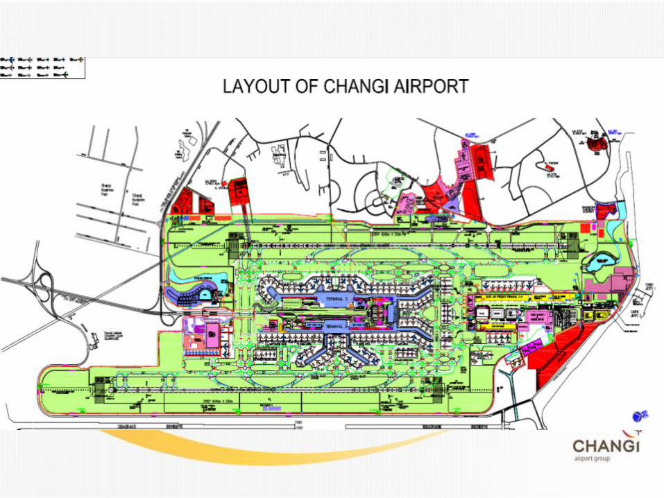
Changi Airport Layout
Runway 02L (
Runway 02C
T2
BT
Runway 20R
Runway 20C
T3 T1
02L AFLCC
20R AFLCC
NA AFLCC
02C AFLCC
20C AFLCC

9
RUNWAY 1
RUNWAY 2
02L
approach
20C
approach 02C
approach
20R
approach
4000 X 60 metres
4000 X 60 metres
(CAT II)
(CAT II)
(CAT I)
(CAT I)
Control Tower

2. Runway Lighting System
1. Approach Lighting System
3. Taxiway Lighting System
Types of Airfield Lighting Systems

1. Approach Lighting System

20R - Distance Coded Approach (Cat 1)

20R - Distance Coded Approach (Cat 1)

02C - Barrette Approach (CAT 1)
30m
CIRCULAR GUIDANCE LIGHT
SEQUENTIAL STROBE LIGHT
THR
ESHO
LD
600m
CROSS BAR
4m
CENTRE LINE BARRETTE LIGHTS
30m
300m

02L and 20C -Barrette Approach (Cat II & Cat III)
30m
CIRCULAR GUIDANCE LIGHT
SEQUENTIAL STROBE LIGHT
THR
ESHO
LD
600m 300m
150m
CROSS BAR CROSS BAR
4m
4m
30m
SIDE ROW BARRETTE LIGHTS
CENTRE LINE BARRETTE LIGHTS
30m
7m
7m


17
Approach Lighting System

2. Runway Lighting System
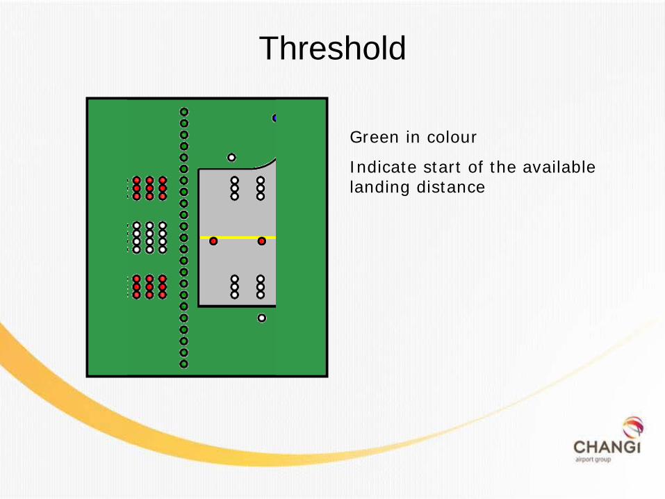
Threshold
Green in colour
Indicate start of the available landing distance
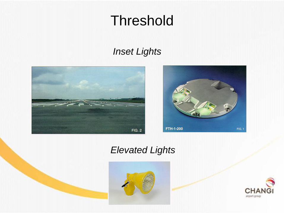
Threshold
Inset Lights
Elevated Lights

Touch Down Zone
•Turn on only during Cat II •900m from the threshold •30m apart

Runway Centre Light
•Bi-directional inset lights •Fitted 30m apart •Landing : using white lights •Take off : alternate between red/white for the initial 600m and red for the last 300m from the end of runway

23
Runway Centre Line & Touchdown Zone
Touchdown zone lights
Runway centre line light

24
Precision Approach Path Indicator (PAPI)
Provides visual guidance to pilots to achieve correct approach slope of 3° during landing

PAPI

Runway Edge
• Elevated Light • Placed 60m apart • White lights • Yellow lights for the last 600m from runway • Two rows of lights equidistant from runway centreline

27
Elevated Runway Edge
Elevated runway edge lights

Runway End
Red in colour
Indicates end of runway

1
2
3
4
5


3. Taxiway Lighting System

32
TAXIWAY INSET LEAD-IN
Taxiway inset lead-in lights

33
TAXIWAY EDGE LIGHTS / REFLECTIVE MARKERS
Taxiway edge lights
Taxiway Reflective Markers

34
Taxiway directional guidance sign – Black on yellow background
Taxiway location sign – Yellow on black background
Guidance Signs Runway Sign – White on red background

Video on Introduction of the Airfield Lighting System

36
Electrical Supply for Airfield Lighting
Systems

37
• Power Distribution Utilities Supply (with redundant feed)
Generator Supply
UPS
Constant Current Regulators
Series Circuits in the field (may be interleaved)
Lamp
Other Ancillary Lights not running on series circuits (e.g. Aerodrome and Identification Beacons, Traffic Lights)
Electrical Supply
CAT I – require switch over time of 15 second CAT II – require switch over time of 1 second

38
• Provide constant current throughout the entire airfield lighting circuit
• Provide uniform lamp brightness throughout even in long distance
circuit
• Enable ease of brilliancy control for airfield lights
Constant Current Regulator

Electrical Supply (Changi)
standby generator
Mobile generator
40
Airfield Ground Lighting Control and Monitoring System
(AGLCMS)

Introduction to AGLCMS
Primary Purpose: • Remote control of taxiway & runway airfield lights at Control Tower
• Monitoring of airfield lights and related equipment at Control Tower
• Features include: • Taxiway lighting control • Individual lamp control and monitoring
for runway lights • Aircraft position display on the lighting
control panel
Operations in the Control Tower
Control panels installed in the Control tower

LEGEND ALCMS – Airfield Lighting Control & Monitoring System CU – Controller Unit SCM – Series Circuit Mode PLC – Programmable Logical Controller CCR – Constant Current Regulator
Runway Lighting Circuits
CCR CU
SCM
PLC
ALCMS
Airfield primary cables
Airfield lights
Airfield lights

AGLCMS GUI Display
Screenshot of a full airport display on the AGLCMS monitors.
Radar Tracks
Repositioned and zoomed to area of interest
UTC Time
Landing and takeoff directions
Alarm list

Manual route creation by selecting the starting and ending nodes
Select 1st Node
Select 2nd Node
Execute selected route

User Panel for Control of Brilliancy Level of AFL
Control of the brilliancy level of the airfield lighting can be stepped up/down via the AGLCMS.
46
Runway Inspections and Maintenance


Runways Inspection and Maintenance – 5 inspection closure per day per runway
• 3 slots of 5 minutes • 1 slot of 10 minutes • 1 slot of 15 minutes • Inspect runway lightings, pavement & marking condition and FOD • Replace faulty light fittings if time permit, otherwise mark out and
replace during daily night maintenance closure
– 1 night maintenance closure per night per runway • Closure duration- 1.5hrs/runway • Carry out faulty lights replacement, minor AFL fault rectification,
runway marking painting and minor pavement defect rectification

CCR calibration
Fire protection
Cable ducting works Transformer pit servicing
Runway light replacement
Airfield sign maintenance Traffic light inspection Pavement marking
Runway pothole repair Localised resurfacing Tyre carcass FOD Bird strike handling
Maintenance Activities AFLCC works Airfield lighting cabling and pit servicing
Airfield lighting installation, taxiway sign and traffic light works
Aircraft pavement maintenance Airside inspection and FOD handling

50
UPS
switchboard
AFLCC Inspection
standby generator
Meggar primary cables

Challenges faced • Once a system has been installed, its usefulness is dependent on:
o Its Serviceability o Effectiveness of the maintenance work carried out
• A light is deemed to be unserviceable when the main beam average intensity is less, than 50% of the value specified for that of a new light
• The Total degradation of light output can be attributed to:
o Contaminants inside and outside the fittings o Degradation of optical components
• Limited access time to runways

Airfield Lighting Maintenance Cycle
2. Generate Condition
Report
3. Conduct Maintenance as identified
in report
1. Airfield Lighting cleaning
and testing conducted
monthly
4. Servicing of light fitting
6. Return tested and compliant fittings to
stock
5. test fittings in
light laboratory

• Carry out scheduled AFL and Civil PM, BM and IM works • Cleaning and tightening of runway inset lights • Runway lights photometric testing
1. Airfield Lighting cleaning
and testing conducted
monthly

Photometric Airfield Calibration (PAC) The system is designed to mount on maintenance vehicle As airport runway access time is limited, photometric measurement runs need to be completed as quickly as possible and can be conducted at speeds up to 60 km/hr without affecting accuracy 2 man operation – 1 Driver , 1 operator
2. Generate Condition
Report

Servicing of Light fitting • Light fitting(s) is removed from service due to serviceability levels • The fitting undergoes an overhaul where any faulty or worn
components are replaced. The lamp is also changed and the fitting fully cleaned
• Undergo water tightness test
3. Conduct Maintenance as identified
in report
4. Light fitting
overhaul

Servicing of Light Fitting

Photometric Test • The photometric laboratory enables to prove light fittings
compliance to regulatory requirements • Conducted in ‘Darkroom’ • A report will be generated containing results for that particular fitting
along with that are prescribed by the relevant requirements
5. test fittings in
light laboratory
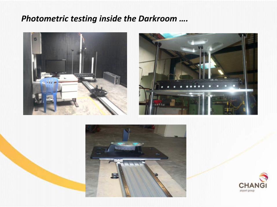
Photometric testing inside the Darkroom ….
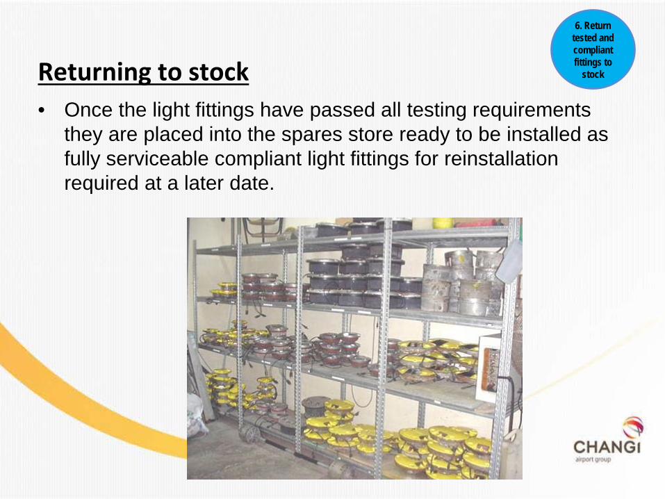
Returning to stock • Once the light fittings have passed all testing requirements
they are placed into the spares store ready to be installed as fully serviceable compliant light fittings for reinstallation required at a later date.
6. Return tested and compliant fittings to
stock
