goldsworth road energy assessment for planning 11-05-2020
TRANSCRIPT

ENERGY STRATEGY
By Couch Perry Wilkes
For Goldsworth Road
Development LLPJune 2020

Appraisal of Energy Options Birmingham | Nottingham | Huntingdon | Leeds | Bristol | Leicester | London | Cambridge City | Manchester cpwp.com 2
Executive Summary Couch Perry and Wilkes LLP has undertaken an Energy Assessment of the proposed Goldsworth Road development in Woking. This report details the performance of the development against the Carbon Dioxide (CO2) emissions and overheating criteria set out in the Building Regulations Part L, and the Woking local planning requirements. It is shown that the building improves upon building regulation CO2 emission targets through fabric and building service efficiencies alone. The addition of CHP(combined heat and power) led District heating technologies further reduce the development’s CO2 emissions to 40.5% over Part L 2013 regulations. The building emission rate is compared to a Target Emission rate below to demonstrate the savings achieved. Note 1. CO2 emission factors of 0.216 for Gas and 0.519 for Electricity have been used to calculate the above and are taken from Building Regulations Approved Documents. Regulated carbon dioxide savings Target Emission Rate Building Emission Rate Reduction (Tonnes CO2 per annum) (%) improvement Non-Domestic Buildings 104.4 83.6 25.1 20.0% Domestic Buildings 983.17 581.78 401.39 40.8% Total Cumulative Savings 1,087.57 665.38 426.49 39.2% As seen above, the scheme is in compliance with the planning requirement of achieving 19% betterment on Part L 2013, by surpassing this, and providing a betterment of 39.2%. This also constitutes to a saving of 426.49 Tonnes of CO2 per annum for the entire site.

Appraisal of Energy Options Birmingham | Nottingham | Huntingdon | Leeds | Bristol | Leicester | London | Cambridge City | Manchester cpwp.com 3
Contents Section Description Page 1.0 Introduction 4 2.0 Energy Benchmarking – Estimated Energy Demands and CO2 Emissions 5 2.1 Assumed Utility Costs 6 2.2 BREEAM 6 3.0 Energy Efficiency – Be Lean 10 3.1 Site Location 10 3.2 Site weather and microclimate 11 3.3 Building Orientation, layout and form 11 3.4 Building Design – Energy Efficiency 13 4.0 Decentralised Energy – Be Clean 18 4.1 Existing Heat Networks 18 4.2 Cooling and Overheating 19 4.2.1 The Cooling Hierarchy 19 4.2.2 Overheating Analysis 19 5.0 Appraisal of Renewable and Low Carbon Technology Energy Options – Be Green 23 5.1 Heat Pump Technologies 25 5.2 Solar Photovoltaic (PV) Panels 25 5.3 Solar Thermal 28 5.3.1 Ground Source Heating and Cooling 30 5.3.2 Wind Turbines 32 5.3.3 Bio-fuel CHP 33 5.3.4 Bio-Renewable Energy Sources – Wood-fuel Boiler Plant 35 5.3.5 Fuel Cells and Fuel Cell Combined Heat and Power 36 5.4 Combined Heat and Power (CHP) 37 5.5 Energy production from LZC 37 6.0 Energy Strategy Results 38 7.0 Appendices 39 7.1 Appendix A - BRUKL Documents (see supplementary Data) 39 7.2 Appendix B – sample SAP data sheets (See supplementary Data) 39

Appraisal of Energy Options Birmingham | Nottingham | Huntingdon | Leeds | Bristol | Leicester | London | Cambridge City | Manchester cpwp.com 4
1.0 Introduction Couch Perry Wilkes (CPW) has produced an Energy Statement for the proposed Goldsworth Road development in Woking. This is to demonstrate how the scheme will incorporate energy efficiency measures, decentralised energy sources and Low and Zero Carbon (LZC) technology solutions to reduce the predicted regulated CO2 emissions of the development by at least 19.0% (CO2 reduction on 2013 building regulations) in accordance with Woking Borough Council Core strategy policy, specifically but not limited to: CS21: Sustainable design CS22: Sustainable construction CS23: incorporation of Low and Zero carbon technologies Description of development: Demolition of the existing buildings and erection of a phased, mixed-use development comprising residential (Class C3), ground floor retail/commercial uses (Class A1-A4, B1, D1-D2), homeless shelter (sui generis) along with public realm and highways alterations to Goldsworth Road, associated car parking and landscaping. The following sets out an Energy Hierarchy for reducing CO2 emissions in the form: Be Lean: use less energy Be Clean: supply energy efficiently Be Green: use renewable energy This report outlines how the proposed development meets the targets set out in the planning policy and through the use of the hierarchy outlined above. The Energy and Sustainability Targets which are examined within this report are the following: Compliance with Building regulations Part L 2013
o Part L1A for Domestic buildings o Part L2A for non-Domestic buildings
Local planning requirement to achieve 19% betterment on Part L 2013 targets Achieve BREEAM rating of ‘VERY GOOD’ (applicable only to non-domestic buildings) Meet TM52 overheating criteria for all non-residential areas. Meet TM59 overheating criteria for all Residential accommodation.

Appraisal of Energy Options Birmingham | Nottingham | Huntingdon | Leeds | Bristol | Leicester | London | Cambridge City | Manchester cpwp.com 5
The Energy and thermal modelling has been broken down into the following packages and analysed as follows: Homeless Shelter – Communal areas – BRUKL report generated using IES Virtual Environment 2019 software. 11 Retail units - BRUKL report generated using IES Virtual Environment 2019 software. Tenant amenity space - BRUKL report generated using IES Virtual Environment 2019 software. 965 Residential units – Simulated under SAP 2012 (10% overall tested) 2.0 Energy Benchmarking – Estimated Energy Demands and CO2 Emissions In order to benchmark the proposed new development, estimated energy demands and CO2 emissions data have been calculated. These estimated energy consumptions are indicative only at this stage. They will, however, be used as a guideline to assess the percentage of the building’s total energy consumption and CO2 emissions that could be reduced or offset in accordance with the Energy Hierarchy. In accordance with energy assessment guidance, it is prudent for this report to reflect the benchmark data derived from approved Dynamic Simulation Model (DSM) software which use government and industry agreed National Calculation Methodology (NCM) room templates containing standard operating conditions.

Appraisal of Energy Options Birmingham | Nottingham | Huntingdon | Leeds | Bristol | Leicester | London | Cambridge City | Manchester cpwp.com 6
The modelling confirms the predicted notional regulated CO2 emissions are as follows: Building Regulations 2013 Part L Compliant Development Notional Carbon Dioxide Emissions (Tonnes CO2 per annum) Regulated Unregulated* Homeless Shelter – communal areas 28.4 23.9 Commercial / Retail units 47.8 148 Tenant Amenity space 28.2 23.1 SAP results 983.17 - Total 1,087.57 195 *unregulated load calculated using Part L software Table 1 – Notional CO2 Emissions Note 1. CO2 emission factors of 0.216 for Gas and 0.519 for Electricity have been used to calculate the above and are taken from Building Regulations Approved Documents. 2.1 Assumed Utility Costs The following utility costs have been assumed in order to assess payback periods only: Gas = £0.03/kWhr Electricity = £0.09/kWhr 2.2 BREEAM BREEAM or Building Research Establishment’s Environmental Assessment Method is a voluntary scheme that aims to quantify and reduce the environmental burdens of buildings by rewarding those designs that take positive steps to minimise their environmental impacts. Projects are assessed using a system of credits. The credits are grouped within the following categories: Management Health and Wellbeing Energy Transport Water Materials Waste Land Use and Ecology Pollution

Appraisal of Energy Options Birmingham | Nottingham | Huntingdon | Leeds | Bristol | Leicester | London | Cambridge City | Manchester cpwp.com 7
The assessment process results in a report covering the issues assessed together with a formal certification giving a rating on a scale of UNCLASSIFIED, PASS, GOOD, VERY GOOD, EXCELLENT and OUTSTANDING. The diagram and text below describes how BREEAM scores and rates an assessed building: The BREEAM categories contain a number of environmental issues, which reflect the options available when designing, procuring and constructing a building. Tradable Credits Each environmental issue has a set number of ‘credits’ available and these credits are awarded where the building demonstrates that it complies with the requirements of that issue. Minimum Standards A number of issues within a category have set minimum standards, i.e. a minimum number of credits that must be achieved in order for a particular BREEAM rating level to be met. Innovation Credits Innovation credits provide additional recognition for a building that innovates in the field of sustainable performance, above and beyond the level that is currently recognised and rewarded by standard BREEAM issues. Innovation credits are awarded for either complying with pre-defined BREEAM issue exemplary level requirements, or via application to BRE Global to have a particular building feature, system or process recognised as ‘innovative’.
Figure 1 - Process for awarding a BREEAM rating

Appraisal of Energy Options Birmingham | Nottingham | Huntingdon | Leeds | Bristol | Leicester | London | Cambridge City | Manchester cpwp.com 8
Within each of the BREEAM categories outlined above, there are a number of credit requirements that reflect the options available to designers and managers of buildings. An environmental weighting is applied to the scores achieved under each category, as shown below, in order to calculate the final BREEAM score. The weighting factors have been derived from consensus based research with various groups such as government, material suppliers and lobbyists. This research was carried out by BRE Global to establish the relative importance of each environmental issue. The environmental weightings are as follows: The BREEAM rating bands are as follows: BREEAM Rating Score (%) UNCLASSIFIED <30 PASS ≥30 GOOD ≥45 VERY GOOD ≥55 EXCELLENT ≥70 OUTSTANDING ≥85 Table 2 - BREEAM rating bands Although, at this stage, it is very difficult to predict exactly the number of BREEAM credits likely to be achieved by each LZC technology when applied to the current development, it is worth noting that these technologies have an influence over the following: Figure 2 - BREEAM 2014 New Construction section weighting

Appraisal of Energy Options Birmingham | Nottingham | Huntingdon | Leeds | Bristol | Leicester | London | Cambridge City | Manchester cpwp.com 9
Ene 1 Reduction of CO2 Emissions – Up to 12 (+5 Innovation) credits are available. Ene 4 Low Carbon Design – One credit is available. Pol 2 NOx Emissions – Up to 3 credits are available

Appraisal of Energy Options Birmingham | Nottingham | Huntingdon | Leeds | Bristol | Leicester | London | Cambridge City | Manchester cpwp.com 10
3.0 Energy Efficiency – Be Lean In order to deliver an environmentally responsible building, an exemplar approach is being proposed based on low energy design principles. In summary, this approach involves energy demand minimisation through effective building form and orientation, good envelope design and proficient use of services; such that the building itself is being used as the primary environmental modifier. Long term energy benefits are best realised by reducing the inherent energy demand of the building in the first instance. These benefits are described and quantified in the following sections. 3.1 Site Location The proposed site is located in the heart of Woking city Centre, South-West of London along the main artery of Goldsworth Road. A number of low-rise building are currently located here which are due to be demolished. The majority of the surrounding buildings are generally quite low lying with the exception to the Victoria road development across the street to the North East of the site, which features a tower block comparable in size to Tower 3 of Goldsworth Road; a 34 storey residential block.

Appraisal of Energy Options Birmingham | Nottingham | Huntingdon | Leeds | Bristol | Leicester | London | Cambridge City | Manchester cpwp.com 11
3.2 Site weather and microclimate The local weather and any microclimate will also influence energy usage. A development on the coast may have a maritime climate, experiencing milder winters and cooler summers than those further inland, particularly on the west coast where they are subject to the jet stream influence. Inland buildings will have a continental climate, suffering more extremes in temperature and therefore more likely to require heating and cooling. The climate in Woking city centre is warm and temperate with annual average temperatures of approx. 10.0C. Woking lies 33m above sea level and there is significant rainfall throughout the year. Maximum temperatures can reach up to 22C in July and August, and minimum temperatures are unlikely to drop below 0-1C in the winter months. The buildings in this area generally low rise to one side, but being a city centre with high rise buildings to the North-East, the area might suffer from any Urban Heat Island effects, which could generate temperatures of up to 25C in the summer months. The nearest weather station is in Heathrow (approx. 12 miles away), and this will be used for any thermal simulations. The site’s landscape also affects the energy demand of a building. Vegetation, land form and any existing buildings can provide shade to a new development. For example, if located to the south of the building, deciduous trees can be advantageous, providing shade in the summer but allowing sunshine through in the winter when they lose their leaves. However, any tree used for energy conservation should be considered as part of a much larger landscape. As part of the regeneration and pedestrianisation of Goldsworth road, the landscape strategy aims to see the planting many trees and green spaces around this are, which are expected to have a positive effect on the site’s environmental conditions; providing shade, and a cooler environment. 3.3 Building Orientation, layout and form Building layout, orientation and form can influence many key features of the development. The design should provide for an effective use of space and appealing layout, with opportunities to benefit from natural daylight balanced with achieving solar gain without overheating. In general, a higher thermal performance can be achieved by limiting the surface area to volume ratio as this minimises heat loss through the wall area. By orientating the building, so that the long sides of the building face north and south, glare arising from the low early morning and evening sun is designed out. It should be noted that where the building footprint is extremely tight, for example in a city centre location, then the building form and orientation may have to be dictated by the available space and not by implementation of best practice measures. Invariably, planning constraints and/or the functional relationships of specific areas will result in some measure of deep planning, thus reducing the opportunity for natural ventilation. Solar heating or solar gain is often welcome in winter months, helping to heat up the building. However, careful design and attention to building orientation is essential to avoid summertime overheating, as on a clear day in summer an unshaded window in the UK can admit 3kWhr of energy per m2 of glass. Overheating is likely to be more of a problem if the windows face the southern half of the sky (east or west facing windows can also be a problem in some types of building), there are horizontal or near-horizontal rooflights, the building has high internal heat gains or the building needs to be kept cooler than normal.

Appraisal of Energy Options Birmingham | Nottingham | Huntingdon | Leeds | Bristol | Leicester | London | Cambridge City | Manchester cpwp.com 12
Planning the internal layout of buildings and rooms to maximise the benefits of solar gain and minimise the disadvantages is essential. Spaces where overheating would be critical can be placed on the north side of the building or overhangs used to protect from excessive solar gain. The Majority of Commercial spaces face North to North-West and are for the most part protected from the effects of extreme solar irradiation. All occupied spaces have access to the external envelope and hence access to a form of natural daylight and ventilation. All retail accommodation is located on the ground floor of the development within the podium. The Tenant amenity space is located on Level 3 at the base of the Residential accommodation. The Tenant amenity space accommodation is located to the north side of the podium making the location ideal as this limits solar gains within Gyms, Studios and Sauna / Steam room spaces where internal gains are already high. The residential accommodation is contained within each residential tower from Levels 3 to Level 39 on the tallest Tower 3. Where balconies are provided to Living room areas, these provide solar shading to window openings on floors directly below. This is increasingly important in the case of the South and West facing apartments. The Podium building form factor is approximately 0.2 which means that we have good floor area to heat loss surface area ratio. This assists the commercial building element in minimising heat losses and improving the likelihood of achieving a good air tightness.

Appraisal of Energy Options Birmingham | Nottingham | Huntingdon | Leeds | Bristol | Leicester | London | Cambridge City | Manchester cpwp.com 13
3.4 Building Design – Energy Efficiency The general construction design standards to be adopted must exceed the requirements of the current (2013 Edition) Part L Building Regulations. To this end, the proposed design shall promote reduced CO2 emissions from delivered energy consumption by minimising operational energy demand through passive and best-practice measures. The LZC technology energy options presented herein will potentially provide a further CO2 reduction over and above the measures included as an integral part of the project design. Be Lean – use less energy Being lean is all about utilising passive, often simple measures to help reduce the energy consumption to a sensible minimum level. For this project we started with the thermal envelope. Using traditional construction methods, we have been able to engineer the building envelope to minimise heat loss in winter and minimise unwanted heat gain in summer. This has been achieved by:- Enhanced envelope U-values - to reduce the building’s heating requirements; Providing a well-sealed envelope to minimise the infiltration of cold winter air - to reduce the building’s heating requirement; Minimising thermal bridging by careful structural and architectural detailing - to reduce the building’s heating requirement; Adopting a window design that optimises daylight but controls solar gain and glare – to reduce electric lighting energy consumption; Providing exposed thermal mass where possible to provide passive cooling – supresses summertime overheating to acceptable levels without the need for high energy consuming and expensive to run and maintain mechanical cooling systems. Considering the layout and orientation of the building - to minimise summertime overheating and the need for high energy consuming and expensive to run and maintain mechanical cooling systems.

Appraisal of Energy Options Birmingham | Nottingham | Huntingdon | Leeds | Bristol | Leicester | London | Cambridge City | Manchester cpwp.com 14
The following diagram illustrates the approach we have adopted: The application of exposed thermal mass to provide passive cooling is well understood and is an excellent method of supressing the fluctuations of internal temperature without resorting to mechanical cooling systems, which are both expensive to install, consume significant amounts of energy in summer and have high maintenance costs. In occupied spaces and where possible, this passive cooling will be provided by exposing the concrete floor. The exposed thermal mass will absorb room heat gains during the day allowing the spaces to remain comfortable and compliant with the overheating criteria. Stored heat will be released at night by means of the mixed mode ventilation philosophy. This will regenerate the exposed concrete’s ability to absorb heat the following day. The process is described in more detail later in the report. Ceilings will be finished with a high reflective coating to optimise daylight, especially towards the back corners of the rooms. It will also improve the artificial light uniformity and improve its energy efficiency. The window design has been carefully considered to enable optimum daylight transmission while still affording natural ventilation with or without the blinds down. Importantly the structural engineering solution for the building allows the window head height to be maximised so they finish immediately below the soffit. This, together with the generous ceiling height has allowed us to meet and exceed the daylighting criteria. The development’s thermal envelope performance will be better than that required by the Building Regulations to minimise heat loss and therefore minimise the heating energy consumed. This will be achieved by improving the U-Values and by having a very tight thermal envelope to minimise the opportunity for heat to escape. We propose to design the building envelope to deliver an air leakage rate better than 3m³/hr/m² at 50 Pa, considerably better than the Building Regulation minimum of 10m3/hr/m² at 50 Pa. Fabric First Energy Strategy – Thermal Envelope Aligned with our Energy Strategy we promote a thermally efficient building fabric specification in order to inherently reduce the energy consumption of the building. This strategy designs out the need for Renewables (LZC) solutions that are disproportionally expensive and ensures the construction budget is put into the building.

Appraisal of Energy Options Birmingham | Nottingham | Huntingdon | Leeds | Bristol | Leicester | London | Cambridge City | Manchester cpwp.com 15
The table below shows the proposed building fabric thermal performance for the non-residential areas: Element Criteria U-Value (W/m2K) Notes U-Value Improvement over Part L 2013 regulations General Glazing U = 1.3 Glass to achieve a total light transmission of 0.69 G-Value of 0.4 to South and West facing windows G-value 0.6 to North and East facing windows 41% Wall U = 0.15 Thermal mass to inner leaf 40% Roof U = 0.1 Light weight construction. 45% Ground/ Basement Floor U = 0.12 - 60% Internal Glass Partitions - Glass to achieve a total light transmission of 0.69 - Ceiling / Soffit - To achieve a minimum reflectance of 80%. Painted concrete and false ceilings. - Internal Wall - To achieve a minimum reflectance of 60%. Internal partitions and internal surfaces of external walls. - Floor - To achieve a minimum reflectance of 25 - 30% - Thermal Bridging Ψ value 0.09 w/mK or better Thermal bridging elements will be either designed out completely or their specification will be carefully detailed to minimise heat transmission through the envelope. -

Appraisal of Energy Options Birmingham | Nottingham | Huntingdon | Leeds | Bristol | Leicester | London | Cambridge City | Manchester cpwp.com 16
The table below shows the proposed building fabric thermal performance for the residential areas: Element Criteria U-Value (W/m2K) Notes U-Value Improvement over Part L 2013 regulations General Glazing U = 1.5 Glass to achieve a total light transmission of 0.69 G-Value of 0.4 to South and West facing windows G-value 0.6 to North and East facing windows 30% Wall U = 0.20 Thermal mass to inner leaf 30% Roof U = 0.1 Light weight construction. 45% Ground/ Basement Floor U = 0.12 - 60% Internal Glass Partitions - Glass to achieve a total light transmission of 0.69 - Ceiling / Soffit - To achieve a minimum reflectance of 80%. Painted concrete and false ceilings. - Internal Wall - To achieve a minimum reflectance of 60%. Internal partitions and internal surfaces of external walls. - Floor - To achieve a minimum reflectance of 25 - 30% - Thermal Bridging Ψ value 0.09 w/mK or better Thermal bridging elements will be either designed out completely or their specification will be carefully detailed to minimise heat transmission through the envelope. -
Appraisal of Energy Options Birmingham | Nottingham | Huntingdon | Leeds | Bristol | Leicester | London | Cambridge City | Manchester cpwp.com 17
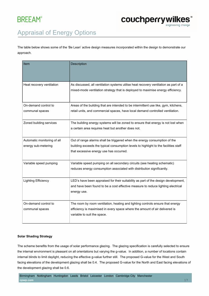
The table below shows some of the ‘Be Lean’ active design measures incorporated within the design to demonstrate our approach. Item Description Heat recovery ventilation As discussed, all ventilation systems utilise heat recovery ventilation as part of a mixed-mode ventilation strategy that is deployed to maximise energy efficiency. On-demand control to communal spaces Areas of the building that are intended to be intermittent use like, gym, kitchens, retail units, and commercial spaces, have local demand controlled ventilation. Zoned building services The building energy systems will be zoned to ensure that energy is not lost when a certain area requires heat but another does not. Automatic monitoring of all energy sub-metering Out of range alarms shall be triggered when the energy consumption of the building exceeds the typical consumption levels to highlight to the facilities staff that excessive energy use has occurred. Variable speed pumping Variable speed pumping on all secondary circuits (see heating schematic) reduces energy consumption associated with distribution significantly. Lighting Efficiency LED’s have been appraised for their suitability as part of the design development, and have been found to be a cost effective measure to reduce lighting electrical energy use. On-demand control to communal spaces The room by room ventilation, heating and lighting controls ensure that energy efficiency is maximised in every space where the amount of air delivered is variable to suit the space. Solar Shading Strategy The scheme benefits from the usage of solar performance glazing. The glazing specification is carefully selected to ensure the internal environment is pleasant on all orientations but varying the g-value. In addition, a number of locations contain internal blinds to limit daylight, reducing the effective g-value further still. The proposed G-value for the West and South facing elevations of the development glazing shall be 0.4. The proposed G-value for the North and East facing elevations of the development glazing shall be 0.6.

Appraisal of Energy Options Birmingham | Nottingham | Huntingdon | Leeds | Bristol | Leicester | London | Cambridge City | Manchester cpwp.com 18
4.0 Decentralised Energy – Be Clean 4.1 Existing Heat Networks Opportunities to connect the planned development to existing or future decentralised heat distribution networks, including those featuring Combined Heat and Power (CHP) plant, have been investigated. Woking Borough Council Core strategy policy CS 23 outlines a requirement for connection to decentralised heat networks. Investigations have been carried out into the viability of connection into a local district heating network. It was found that, currently, Thameswey LTD have a proposed Energy centre development underway that is being created specifically to accommodate the surrounding region by supplying all required district heating and cooling requirements. The Goldsworth road development intends to connect to these systems for both heating and cooling. Based on the information shared by Thameswey, the following criteria have been assumed in this case, and for the purposes of the Energy and SAP modelling: District heating Energy generated at the Energy centre shall be provided by a 66/33 split between Combined heat & Power / Boiler systems, offering a system carbon factor of approximately 0.169kgCo2/kWh District cooling Energy is generated by heat pump systems at the Energy centre providing an SEER of approximately 3.64 Connecting to the district heating systems which are powered by CHP and heat pumps provides a considerably saving on carbon for the development, as demonstrated in the results later in this report. The district heating and cooling systems shall serve the heating and cooling requirements of the residential elements specifically. All commercial units shall be served by local decentralised heat pump systems either via VRF or DX heating and cooling systems, to satisfy internal comfort criteria.

Appraisal of Energy Options Birmingham | Nottingham | Huntingdon | Leeds | Bristol | Leicester | London | Cambridge City | Manchester cpwp.com 19
4.2 Cooling and Overheating 4.2.1 The Cooling Hierarchy Based on Good practice procedures, a hierarchy of measures should be followed in order to reduce the demand for cooling within a development. These have been included in the Goldsworth Road development as follows: 1. Minimising Internal Heat Gains – DHW pipe work will be designed and insulated to minimise heat loss into the building. For residential accommodation, Danish standards DS439 have been used in order to provide a good level of diversification when sizing heating and hot water systems. In Commercial accommodation, kitchens and high heat spaces shall be situated away from areas of high solar gains. 2. Reducing Solar Gains – As stated in the Be Lean section, a low G-Value has been targeted in order to minimise solar gains. Solar shading will also be considered on the southern façade to combat overheating in certain rooms. 3. Thermal Mass – Thermal mass is being incorporated though the floor slabs and roof, which will comprise concrete planks. Suspended ceilings are likely to be required for acoustic reasons, however further investigation will be undertaken as to the design of these and the floor finishes to try to utilise and expose the thermal mass of the concrete floors wherever possible, so as to help regulate the internal temperature. 4. Passive Ventilation – Where natural ventilation is not applicable, mechanical ventilation will be carefully specified, to reduce energy demand to a minimum. 5. Mechanical Ventilation – Supply and extract systems will be specified with heat recovery and heater batteries to minimise energy use of the system. 4.2.2 Overheating Analysis A detailed analysis has being undertaken to determine whether or not rooms will overheat during the summer. The areas have been thermally modelled to comply with CIBSE TM52 (for non-residential spaces) and CIBSE TM59 (for residential accommodation) Overheating Criteria using CIBSE certified Level 5 approved Dynamic Simulation Modelling software. The software conducts a Dynamic Thermal analysis of the space based upon a weather file derived from CIBSE calculations (Summer Design Year). The weather data files used by the modelling software are provided based on recorded data for the nearest geographical location, these provide details on temperature, solar irradiation, wind speed, wind direction etc. The data has been interpreted by the issuing authority such that it gives the anticipated maximum loads for a current design summer year. The results confirm the thermal comfort within a particular room throughout the summer months. The TM52 Adaptive Comfort analysis tool within IES is capable of assessing overheating of buildings based on the criteria defined by BS EN15251 and BREEAM requirements.

Appraisal of Energy Options Birmingham | Nottingham | Huntingdon | Leeds | Bristol | Leicester | London | Cambridge City | Manchester cpwp.com 20
Commercial accommodation: All commercial accommodation is proposed to be fully comfort cooled and hence is considered to be in compliance with all TM52 overheating limitations. This includes the following areas: Homeless shelter communal areas Retail units Tenants amenity space Residential accommodation The residential spaces have been tested under TM59 for overheating compliance and the following critical assumptions have been made at this point in order achieve the targets : The overheating strategy relies on natural ventilation and opening windows within each room Windows shall have opening restrictors allowing for 17% free area Internal doors within apartments require to be opened at times to achieve overheating compliance. Blinds have been included in all apartments Top floor balconies on the South and west elevations will require solar shading. The below weather files have been tested from the London Gatwick weather station data: Weather File: London_LGW_DYS1_2020 (50th Percentile Range) Results displayed below:

Appraisal of Energy Options Birmingham | Nottingham | Huntingdon | Leeds | Bristol | Leicester | London | Cambridge City | Manchester cpwp.com 21 The results of our analysis demonstrate that the selected rooms tested under the current DSY 1 weather scenario, are in full compliance with the perceived industry design standard stated above, with each room passing at least one criterion out of three defined by TM52 & TM59. Noise Pollution and Active cooling As a result of the acoustic consultant’s report it has been determined that there are high levels of noise pollution being generated towards the Southern side of the side of the site, as a result of the operations of the railway and noise from Day aggregates. The effect of this means that a number of apartments predominantly located towards the South elevations and

Appraisal of Energy Options Birmingham | Nottingham | Huntingdon | Leeds | Bristol | Leicester | London | Cambridge City | Manchester cpwp.com 22
the majority of the west elevations of Towers 1,2&3, are unable to rely on opening windows to deal with the effects of overheating. This is due to the duration of window opening required throughout the year, and the levels of noise experienced within the apartments. At this point a high level analysis identifies approximately 290 units are affected by this noise issue and hence are not able to rely on natural ventilation to deal with overheating issues. Further detailed assessments by the acoustician will confirm the precise extent of this in the following stages of design. In this instance, the effected units shall be provided with active cooling systems to achieve this compliance. The development seeks to connect to Thameswey’s district cooling network and distribute cooling through the residential blocks via a central cooling plate exchanger. Each effected apartment will additionally include a cooling interface unit within the utility cupboard that has the ability to provide cooling to the spaces via local fan convectors in bedrooms and living areas.

Appraisal of Energy Options Birmingham | Nottingham | Huntingdon | Leeds | Bristol | Leicester | London | Cambridge City | Manchester cpwp.com 23
5.0 Appraisal of Renewable and Low Carbon Technology Energy Options – Be Green In accordance with BREEAM requirements, the technical feasibility and economic viability of installing each LZC technology at the development have been assessed, so as to discount any unsuitable options at an early stage. A summary of the feasibility process is tabulated below and an overview of each viable technology is given subsequently. Technology Brief Description Benefits Issues/Limitations Feasible for Site? Solar Photovoltaic Solar photovoltaic panels convert solar radiation into electrical energy through semiconductor cells. They are not to be confused with solar panels which use the sun’s energy to heat water (or air) for water and space heating. Low maintenance/no moving parts Easily integrated into building design No ongoing costs Income generated from Feed-in Tariff (FIT) Any overshadowing reduces panel performance Panels ideally inclined at 30º to the horizontal facing a southerly direction Yes, but limited unshaded roof space available Solar Thermal Solar thermal energy can be used to contribute towards space heating and hot water requirements. The two most common forms of collector are panel and evacuated tube. Low maintenance Little/no ongoing costs Income generated from Renewable Heat Incentive (RHI) scheme Must be sized for the building hot water requirements Panels ideally inclined at 30º to the horizontal facing a southerly direction No, not suitable on this site. Limited available roof space to make this viable. Ground Source Heat Pump (GSHP) GSHP systems tap into the earth’s considerable energy store to provide both heating and cooling to buildings. A number of installation methods are possible including horizontal trench, vertical boreholes, piled foundations (energy piles) or plates/pipe work submerged in a large body of water. The design, installation and operation of GSHPs is well established. Minimal maintenance Unobtrusive technology Flexible installation options to meet available site footprint Income generated from Renewable Heat Incentive (RHI) scheme Large area required for horizontal pipes Full ground survey required to determine geology More beneficial to the development if cooling is required Integration with piled foundations must be done at an early stage No, not suitable on this site, expensive Air Source Heat Pump Electric or gas driven air source heat pumps extract thermal energy from the surrounding air and transfer it to the working fluid (air or water). Efficient use of fuel Relatively low capital costs Specialist maintenance More beneficial to the development if cooling is required Requires defrost cycle in extreme conditions Some additional plant space required No, not suitable on this site
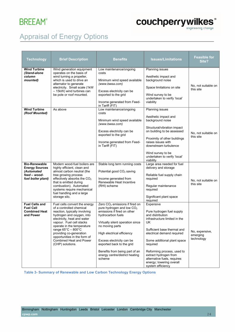
Appraisal of Energy Options Birmingham | Nottingham | Huntingdon | Leeds | Bristol | Leicester | London | Cambridge City | Manchester cpwp.com 24
Technology Brief Description Benefits Issues/Limitations Feasible for Site? Wind Turbine (Stand-alone column mounted) Wind generation equipment operates on the basis of wind turning a propeller, which is used to drive an alternator to generate electricity. Small scale (1kW – 15kW) wind turbines can be pole or roof mounted. Low maintenance/ongoing costs Minimum wind speed available (www.bwea.com) Excess electricity can be exported to the grid Income generated from Feed-in Tariff (FIT) Planning issues Aesthetic impact and background noise Space limitations on site Wind survey to be undertaken to verify ‘local’ viability No, not suitable on this site Wind Turbine (Roof Mounted) As above Low maintenance/ongoing costs Minimum wind speed available (www.bwea.com) Excess electricity can be exported to the grid Income generated from Feed-in Tariff (FIT) Planning issues Aesthetic impact and background noise Structural/vibration impact on building to be assessed Proximity of other buildings raises issues with downstream turbulence Wind survey to be undertaken to verify ‘local’ viability No, not suitable on this site Bio-Renewable Energy Sources (Automated feed – wood-fuel boiler plant) Modern wood-fuel boilers are highly efficient, clean and almost carbon neutral (the tree growing process effectively absorbs the CO2 that is emitted during combustion). Automated systems require mechanical fuel handling and a large storage silo. Stable long term running costs Potential good CO2 saving Income generated from Renewable Heat Incentive (RHI) scheme Large area needed for fuel delivery and storage Reliable fuel supply chain required Regular maintenance required Significant plant space required No, not suitable on this site Fuel Cells and Fuel Cell Combined Heat and Power Fuel cells convert the energy of a controlled chemical reaction, typically involving hydrogen and oxygen, into electricity, heat and water vapour. Fuel cell stacks operate in the temperature range 65°C – 800°C providing co-generation opportunities in the form of Combined Heat and Power (CHP) solutions. Zero CO2 emissions if fired on pure hydrogen and low CO2 emissions if fired on other hydrocarbon fuels Virtually silent operation since no moving parts High electrical efficiency Excess electricity can be exported back to the grid Benefits from being part of an energy centre/district heating scheme Expensive Pure hydrogen fuel supply and distribution infrastructure limited in the UK Sufficient base thermal and electrical demand required Some additional plant space required Reforming process, used to extract hydrogen from alternative fuels, requires energy; lowering overall system efficiency No, expensive, emerging technology Table 3- Summary of Renewable and Low Carbon Technology Energy Options
Appraisal of Energy Options Birmingham | Nottingham | Huntingdon | Leeds | Bristol | Leicester | London | Cambridge City | Manchester cpwp.com 25
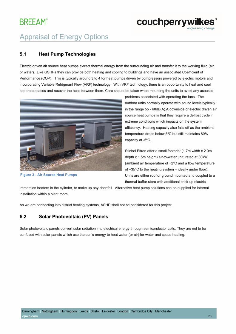
5.1 Heat Pump Technologies Electric driven air source heat pumps extract thermal energy from the surrounding air and transfer it to the working fluid (air or water). Like GSHPs they can provide both heating and cooling to buildings and have an associated Coefficient of Performance (COP). This is typically around 3 to 4 for heat pumps driven by compressors powered by electric motors and incorporating Variable Refrigerant Flow (VRF) technology. With VRF technology, there is an opportunity to heat and cool separate spaces and recover the heat between them. Care should be taken when mounting the units to avoid any acoustic problems associated with operating the fans. The outdoor units normally operate with sound levels typically in the range 55 - 60dB(A).A downside of electric driven air source heat pumps is that they require a defrost cycle in extreme conditions which impacts on the system efficiency. Heating capacity also falls off as the ambient temperature drops below 5ºC but still maintains 80% capacity at -5ºC. Stiebel Eltron offer a small footprint (1.7m width x 2.0m depth x 1.5m height) air-to-water unit, rated at 30kW (ambient air temperature of +2ºC and a flow temperature of +35ºC to the heating system – ideally under floor). Units are either roof or ground mounted and coupled to a thermal buffer store with additional back-up electric immersion heaters in the cylinder, to make up any shortfall. Alternative heat pump solutions can be supplied for internal installation within a plant room. As we are connecting into district heating systems, ASHP shall not be considered for this project. 5.2 Solar Photovoltaic (PV) Panels Solar photovoltaic panels convert solar radiation into electrical energy through semiconductor cells. They are not to be confused with solar panels which use the sun’s energy to heat water (or air) for water and space heating. Figure 3 - Air Source Heat Pumps

Appraisal of Energy Options Birmingham | Nottingham | Huntingdon | Leeds | Bristol | Leicester | London | Cambridge City | Manchester cpwp.com 26
Photovoltaic panels are available in a number of forms including mono-crystalline, polycrystalline, amorphous silicon (thin film) or hybrid panels (discussed later). They are fixed or integrated into a building’s un-shaded south facing façade or pitched roof ideally at an incline of 30º to the horizontal for maximum energy yield. It is essential that the panels remain un-shaded, as even a small shadow can significantly reduce output. The individual modules are connected to an inverter to convert their direct current (DC) into alternating current (AC) which is usable in buildings. Although sloping rooftops provide an ideal site for fixing PV panels using traditional mounting frames, there are a number of alternative solutions whereby PV panels can be incorporated into the actual building fabric of the development. Solar louvres use PV panels to provide solar shading on the south façade of buildings as part of the brise soleil (see above), and this can be a highly effective way of controlling overheating and help reduce glare. Figure 4 - CPW Photovoltaic Installations: Project Epic (BREEAM Excellent Office – above left) and Castle Wood (BREEAM Excellent School – above right) Figure 5 - Solar PV Louvres on the South Facade

Appraisal of Energy Options Birmingham | Nottingham | Huntingdon | Leeds | Bristol | Leicester | London | Cambridge City | Manchester cpwp.com 27 Solar glazing uses a combination of solar PV and glass, where the PV cells are laminated between two panes of specialised glazing (see above). The resulting glass laminate serves the dual function of creating energy and shade at the same time, reducing the risk of overheating. Solar glazing can be used wherever conventional glass would be specified, especially in atria. Bespoke designs allow for varying light penetration by changing the spacing between individual cells. Typically, a combination of 50% PV and 50% translucent glazing is used. Vertical solar facades can be used to directly replace conventional rain screen cladding materials providing a smooth, flat facade surface for the building. Where circumstances allow, the PV panels can be tilted towards the sun to maximize the energy yield. As mentioned earlier, there are a number of types of PV cell: Mono-crystalline Silicon Cells: These are made using cells saw–cut from a single cylindrical crystal of silicon. The principle advantage of mono-crystalline cells is their high efficiency, typically around 15 – 20%, although the manufacturing process required to produce mono-crystalline silicon is complicated, resulting in slightly higher costs than other competing technologies. Polycrystalline Silicon Cells: These are made from cells cut from an ingot of melted and re-crystallised silicon. In the manufacturing process, molten silicon is cast into ingots of polycrystalline silicon. The ingots are then saw-cut into very thin wafers and assembled into complete cells giving a granular textured finish. Polycrystalline cells are cheaper to produce than mono-crystalline types, due to the simpler manufacturing process but tend to be slightly less efficient, with average efficiencies of circa 12 – 15%.
Figure 6 - CPW Solar Glazing Installation, University of Warwick - Materials and Analytical Sciences Building

Appraisal of Energy Options Birmingham | Nottingham | Huntingdon | Leeds | Bristol | Leicester | London | Cambridge City | Manchester cpwp.com 28
Thick-Film Silicon: This is another polycrystalline technology where the silicon is deposited in a continuous process onto a base material giving a fine grained, sparkling appearance. Like all crystalline PV, this is encapsulated in a transparent insulating polymer with a tempered glass cover and usually bound into a strong aluminium frame. Thin-Film Amorphous Silicon: Amorphous silicon cells are composed of silicon atoms in a thin homogenous layer rather than a crystalline structure. Amorphous silicon absorbs light more effectively than crystalline silicon, so the cells can be thinner. For this reason, amorphous silicon is also known as a ‘thin film’ PV technology. Amorphous silicon can be deposited on a wide range of substrates, both rigid and flexible, which makes it ideal for curved surfaces and ‘fold-away’ modules. Amorphous cells are, however, less efficient than crystalline based cells, with typical efficiencies of around 6%, but they are easier and, therefore, cheaper to produce. Other Thin Films: A number of other promising materials such as cadmium telluride (CdTe) and copper indium diselenide (CIS) are now being used for PV modules. The attraction of these technologies is that they can be manufactured by relatively inexpensive industrial processes, certainly in comparison to crystalline silicon technologies, yet they typically offer higher module efficiencies than amorphous silicon. New technologies based on the photosynthesis process are at early stages of commercialisation. Photovoltaic technology is not considered feasible on this project as there are limited unshaded spaces where this can be located, due to the roof containing a number of large-scale plant, and tall buildings causing overshadowing that will greatly reduce the efficiency and yield of a PV system. 5.3 Solar Thermal Solar thermal energy can be used to contribute towards space heating and hot water requirements. In the UK, most applications focus on hot water installation as the solar availability during the space heating season is limited. Figure 7 - CPW Solar Thermal Evacuated Tube Systems: William Brookes School (above left) and

Appraisal of Energy Options Birmingham | Nottingham | Huntingdon | Leeds | Bristol | Leicester | London | Cambridge City | Manchester cpwp.com 29
The use of solar water heating installations is widespread throughout Europe. The systems use a heat collector, generally located at roof level on support frames, orientated in a southerly direction to maximise solar heat absorption. A working fluid is used to heat water that is stored in either a separate hot water cylinder or more commonly a twin coil hot water cylinder with the second coil providing top-up heating from a conventional boiler. The two most common forms of collector are panel and evacuated tube. The panel type collectors are generally more robust and reliable while manufacturers claim that the evacuated tube versions offer better winter all-round performance. The design of the flat plate panels is relatively straightforward; consisting of water tubes arranged behind solar glass and an absorber plate. The absorber plate absorbs the sun’s rays and transfers energy to the water flowing through the tubes. In contrast, the evacuated tube type collectors are more complicated consisting of double wall glass tubes with a space in the centre containing a heat pipe and a liquid. Coatings on the inner glass ensure that around 93% of the absorbed heat is retained within the system and the vacuum prevents loss of heat through conduction and convection. The circular design helps maximise the potential to collect solar energy all year round when the sun is at different angles. Figure 9 - Schematic Diagram of Solar Thermal Energy Transfer and System Operation
Figure 8 - Evacuated Tube Type Collectors

Appraisal of Energy Options Birmingham | Nottingham | Huntingdon | Leeds | Bristol | Leicester | London | Cambridge City | Manchester cpwp.com 30
The heat pipes are connected to a manifold containing circulating water (see Figure 6 above). The liquid in the heat pipe is evaporated by the suns energy and rises to a heat exchanger within the manifold where it condenses and gives up its latent heat energy to the water. This heated water is then pumped to a coil in the hot water cylinder sized to meet the demand of the installation. Evacuated tube systems deliver higher temperature water than flat plate types, with little decrease in efficiency, making them more effective with thermal storage solutions. As a general rule, the evacuated tube collectors can deliver around 700kWhr/m2/yr when in optimum orientation (inclined at 30º to the horizontal facing a southerly direction). This compares to around 580kWhr/m2/yr for the flat plate collectors under similar conditions. Solar thermal installations can be designed to fit the available roof space and/or building façade. Each evacuated tube is approximately 2m in length with an external diameter of 58mm. They weigh around 2kg each and can be spaced from 10mm to 500mm apart in an array. A typical panel array, 2.1m x 1.0m, will provide around 1.33m2 of absorber area and weigh approximately 45kg. Bespoke mounting frames can be fashioned to provide the ideal inclination of 30º to the horizontal facing a southerly direction. Access to the roof mounted solar collectors will be necessary for occasional cleaning of the active tubes. As we are connecting into district heating systems, Solar thermal shall not be considered for this project.. 5.3.1 Ground Source Heating and Cooling The design, installation and operation of Ground Source Heat Pumps (GSHPs) is well established. These geothermal systems tap into the earth’s considerable energy store to provide both heating and cooling to buildings. They take advantage of the fact that at a depth of a few metres, the temperature of the ground remains at a constant 12ºC throughout the year.

Appraisal of Energy Options Birmingham | Nottingham | Huntingdon | Leeds | Bristol | Leicester | London | Cambridge City | Manchester cpwp.com 31
In heating mode, GSHPs absorb energy from the earth and transfer it into the building using highly efficient heat pumps. The effectiveness of heat pumps is measured by the ratio of the heating capacity to the power input, referred to as the Coefficient of Performance (COP). Typically, manufacturers state that for every 1 unit of electrical energy used to drive the pump, around 4 to 5 units of thermal energy can be produced. When operating in cooling mode, during the summer months, the system reverses its cycle and heat is extracted from the building and dissipated into the earth. The ground loops can be installed either vertically in boreholes (typically 50m – 100m deep), or horizontally in trenches at a depth of 1.5m – 2.0m. Either method is dependent upon local geology conditions and space available. The system also benefits from the fact that most of the components are hidden below ground or in plant room enclosures. Costs for drilling vary according to the location and ground conditions. A preliminary site investigation, by means of a desktop study, can usually determine the viability of a ground source heating and cooling system. Fine tuning of the design may be required once actual site ground conditions are established. It should be noted that GSHPs generally deliver water at a temperature approaching 50ºC (which would be ideal for under floor heating). Additional heat sources would be needed to satisfy the requirements for domestic hot water to raise the temperature well above 60ºC. As we are connecting into district heating systems, GSHP shall not be considered for this project. Figure 10 - Ground Source Heat Pump Schematic

Appraisal of Energy Options Birmingham | Nottingham | Huntingdon | Leeds | Bristol | Leicester | London | Cambridge City | Manchester cpwp.com 32
5.3.2 Wind Turbines Wind generation equipment operates on the basis of wind turning a propeller, which is used to drive an alternator to generate electricity. Small scale wind turbines are typically in the range of 1kW – 15kW, with rotor diameters of 2.5m – 9.0m respectively. These systems can be stand-alone or, in some cases, building mounted. The efficiency and effectiveness of wind turbines depends on many factors, not least the average wind speed and wind pattern of the proposed site. Exposed sites, free from obstacles such as buildings and greenery, are more viable than sheltered sites. Column mounted (stand-alone) wind turbines installed at a suitable height above the building line are more effective than wind turbines located at roof level. There are often some planning difficulties associated with the use of wind turbines. Background noise and a phenomenon known as shadow flicker are also potential issues. Typical noise levels measured 20m from the base of an operating 5kW wind turbine (both upstream and downstream) in the range 4m/s to 8m/s are 48 – 50dB(A). At 100m, the predicted noise level would be below 35dB(A). The use of wind turbines is often seen as an obvious statement of a development’s dedication to the use of sustainable technologies. The proposed development does not lend itself to small-scale stand-alone or roof mounted wind turbines due to the high density of multi-storey buildings, obstacles and greenery causing problems with downstream turbulence. The tallest tower locations that can provide unimpeded access to wind are occupied by fire and safety operational plant. For the reasons outlined above, the installation of wind turbines on the site is not practical and will not be considered further. Figure 11 - CPW Designed Helical Roof Mounted

Appraisal of Energy Options Birmingham | Nottingham | Huntingdon | Leeds | Bristol | Leicester | London | Cambridge City | Manchester cpwp.com 33
5.3.3 Bio-fuel CHP Consideration has been given to the possibility of utilising a bio-gas, bio-diesel or dual fuel CHP engine. A dual fuel engine (normally based on field-proven diesel engine technology) can run on oil alone, or a mixture of gas and oil. It should be noted that the engine cannot run on gas alone because it doesn’t have a spark ignition system. Schnell (Germany) supply a range of dual fuel 6 cylinder Scania turbo CHP engines that can be driven on diesel oil, vegetable oil or a mixture of biogas and oil. ENER-G supply a series of 6 to 20-cylinder turbo charged reciprocating CHP engines for biogas applications. As an option, natural gas can be connected into the system, albeit via a separate unit, to provide back-up electrical and heat energy, if required. Dual fuel engine options (biogas and natural gas) are available, but this requires a special upgrade on the engine management system. Fleetsolve Ltd supply a range of 8-cylinder turbo charged reciprocating CHP engines with power options from 18kWe to 2,500kWe. The engines run on a wide range of liquid biomass fuels including a version produced by Fleetsolve from waste vegetable oil and fish oils. This fuel is accredited by Ofgem as a renewable source and is supplied at £0.76 per litre. Due to the nature of the source fuel, the electricity generated qualifies for double ROCs at approximately £94 per MWhr produced. The Fleetsolve CHP unit is housed in its own plant enclosure measuring approximately 4.5m long by 2.0m wide and 2.4m high. The engine is fuelled via a 2,500 heated fuel tank, held at 40⁰C, providing 30 days run time between fill-ups from a road tanker. An exhaust particulate filter and a De-NOx catalytic converter are fitted in the exhaust system. Dry air coolers provide a means of dumping heat energy during periods of over production. The engine is optimised at 1,500rpm with 100% modulation, and operates with a noise level of 45dBA at 10m. Hot water is supplied at 95⁰C with a return temperature of 80⁰C. Figure 12 - Schnell Dual-Fuel Biomass CHP System

Appraisal of Energy Options Birmingham | Nottingham | Huntingdon | Leeds | Bristol | Leicester | London | Cambridge City | Manchester cpwp.com 34
An initial evaluation indicates that the space available on site is too restricting to install a bio fuel CHP system. Furthermore, the site energy requirements are obtained via a CHP led district heating system. Figure 13 - Fleetsolve Liquid Biomass CHP System
Appraisal of Energy Options Birmingham | Nottingham | Huntingdon | Leeds | Bristol | Leicester | London | Cambridge City | Manchester cpwp.com 35
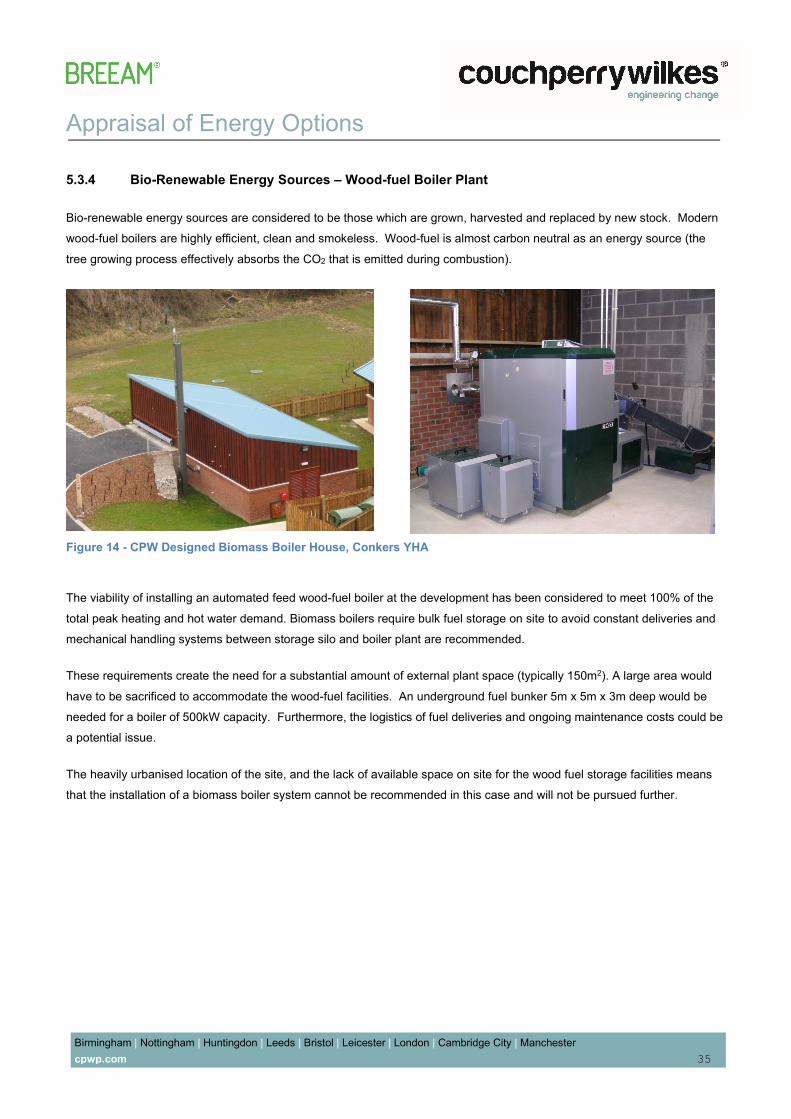
5.3.4 Bio-Renewable Energy Sources – Wood-fuel Boiler Plant Bio-renewable energy sources are considered to be those which are grown, harvested and replaced by new stock. Modern wood-fuel boilers are highly efficient, clean and smokeless. Wood-fuel is almost carbon neutral as an energy source (the tree growing process effectively absorbs the CO2 that is emitted during combustion). The viability of installing an automated feed wood-fuel boiler at the development has been considered to meet 100% of the total peak heating and hot water demand. Biomass boilers require bulk fuel storage on site to avoid constant deliveries and mechanical handling systems between storage silo and boiler plant are recommended. These requirements create the need for a substantial amount of external plant space (typically 150m2). A large area would have to be sacrificed to accommodate the wood-fuel facilities. An underground fuel bunker 5m x 5m x 3m deep would be needed for a boiler of 500kW capacity. Furthermore, the logistics of fuel deliveries and ongoing maintenance costs could be a potential issue. The heavily urbanised location of the site, and the lack of available space on site for the wood fuel storage facilities means that the installation of a biomass boiler system cannot be recommended in this case and will not be pursued further. Figure 14 - CPW Designed Biomass Boiler House, Conkers YHA
Appraisal of Energy Options Birmingham | Nottingham | Huntingdon | Leeds | Bristol | Leicester | London | Cambridge City | Manchester cpwp.com 36
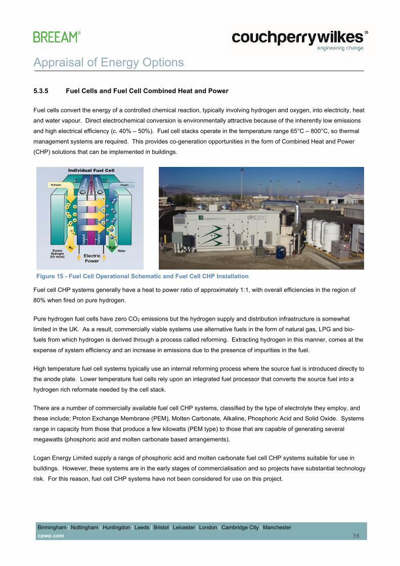
5.3.5 Fuel Cells and Fuel Cell Combined Heat and Power Fuel cells convert the energy of a controlled chemical reaction, typically involving hydrogen and oxygen, into electricity, heat and water vapour. Direct electrochemical conversion is environmentally attractive because of the inherently low emissions and high electrical efficiency (c. 40% – 50%). Fuel cell stacks operate in the temperature range 65°C – 800°C, so thermal management systems are required. This provides co-generation opportunities in the form of Combined Heat and Power (CHP) solutions that can be implemented in buildings. Fuel cell CHP systems generally have a heat to power ratio of approximately 1:1, with overall efficiencies in the region of 80% when fired on pure hydrogen. Pure hydrogen fuel cells have zero CO2 emissions but the hydrogen supply and distribution infrastructure is somewhat limited in the UK. As a result, commercially viable systems use alternative fuels in the form of natural gas, LPG and bio-fuels from which hydrogen is derived through a process called reforming. Extracting hydrogen in this manner, comes at the expense of system efficiency and an increase in emissions due to the presence of impurities in the fuel. High temperature fuel cell systems typically use an internal reforming process where the source fuel is introduced directly to the anode plate. Lower temperature fuel cells rely upon an integrated fuel processor that converts the source fuel into a hydrogen rich reformate needed by the cell stack. There are a number of commercially available fuel cell CHP systems, classified by the type of electrolyte they employ, and these include; Proton Exchange Membrane (PEM), Molten Carbonate, Alkaline, Phosphoric Acid and Solid Oxide. Systems range in capacity from those that produce a few kilowatts (PEM type) to those that are capable of generating several megawatts (phosphoric acid and molten carbonate based arrangements). Logan Energy Limited supply a range of phosphoric acid and molten carbonate fuel cell CHP systems suitable for use in buildings. However, these systems are in the early stages of commercialisation and so projects have substantial technology risk. For this reason, fuel cell CHP systems have not been considered for use on this project. Figure 15 - Fuel Cell Operational Schematic and Fuel Cell CHP Installation

Appraisal of Energy Options Birmingham | Nottingham | Huntingdon | Leeds | Bristol | Leicester | London | Cambridge City | Manchester cpwp.com 37
5.4 Combined Heat and Power (CHP) A CHP installation is effectively an on-site mini power plant providing both electrical power and thermal heat. CHP is strictly an energy efficiency measure rather than a renewable energy technology. A CHP system operates by burning a primary fuel (normally natural gas) by use of either a reciprocating engine or turbine, which in turn drive an alternator to generate electrical power. The heat emitted by the engine and exhaust gases is recovered and used to heat the building or to provide hot water. The viability of CHP is dependent upon the building base load requirements for both heat and power. 24 hour buildings with high heat demands and constant power demands lend themselves to CHP. The noise levels associated with a CHP installation should not be overlooked. Typically, acoustic enclosures and upgraded low noise attenuators are employed to ensure noise levels don’t exceed 65dBA when 1m from the unit. On confined sites, the plant room structure can be enhanced and attenuators fitted to the mechanical ventilation to prevent any noise issues. Noise emissions are of the order of 52dBA – 56dBA. Additional CHP plant can be easily (1 day) retrofitted and connected to the existing buffer store if capacity dictates and plant room space allows. This scheme is deemed viable for the application of CHP. However, as the energy centre that provides the site with District heating, already incorporates 66% heat production via CHP, this offers a considerable carbon saving for the site. Hence no on-site local CHP systems have been proposed. 5.5 Energy production from LZC As described above the No LZC’s have been adopted within this scheme. Figure 16 - Gas Fired CHP System

Energy Statement
Birmingham | Nottingham | Huntingdon | Leeds | Bristol | Leicester | London | Cambridge City | Manchester cpwp.com 38
6.0 Energy Strategy Results It is shown that the building improves upon building regulation CO2 emission targets through fabric and building service efficiencies alone. The addition of CHP led district heating technologies further reduces the development’s CO2 emissions to 40.5% over Part L 2013 regulations. The modelling confirms the predicted actual regulated CO2 emissions are as follows: Building Regulations 2013 Part L Compliant Development Actual Carbon Dioxide Emissions (Tonnes CO2 per annum) Improvement against notional Regulated Unregulated* Homeless Shelter – communal areas 26.6 28.9 6.3% Retail units 31.5 102.2 34.1% Tenant amenity space 25.5 20.6 9.6% SAP results 581.78 - 40.8% Total 665.38 - *unregulated load calculated using Part L software Table 4 – Notional CO2 Emissions The building emission rate is compared to a Target Emission rate below to demonstrate the savings achieved. Note 1. CO2 emission factors of 0.216 for Gas and 0.519 for Electricity have been used to calculate the above and are taken from Building Regulations Approved Documents. Regulated carbon dioxide savings Target Emission Rate Building Emission Rate Reduction (Tonnes CO2 per annum) (%) improvement Non-Domestic Buildings 104.4 83.6 25.1 20.0% Domestic Buildings 983.17 581.78 401.39 40.8% Total Cumulative Savings 1,087.57 665.38 426.49 39.2%

Energy Statement
Birmingham | Nottingham | Huntingdon | Leeds | Bristol | Leicester | London | Cambridge City | Manchester cpwp.com 39
As seen above, the scheme is in compliance with the planning requirement of achieving 19% betterment on Part L 2013, by surpassing this, and providing a betterment of 39.2%. This also constitutes to a saving of 426.49 Tonnes of CO2 per annum for the entire site. 7.0 Appendices 7.1 Appendix A - BRUKL Documents (see supplementary Data) 7.2 Appendix B – sample SAP data sheets (See supplementary Data)