go power! manual
TRANSCRIPT

Owner’s Manual | GP-PWM-25 Regulator
1
© 2010 Carmanah Technologies Corporation Last revised March 2010
Go Power! Manual GP-PWM-25 Regulator

Owner’s Manual | GP-PWM-25 Regulator
2
© 2010 Carmanah Technologies Corporation Last revised March 2010

Owner’s Manual | GP-PWM-25 Regulator
3
© 2010 Carmanah Technologies Corporation Last revised: March 2010
CONTENTS 1.0 Installation Overview 5
1.1 Introduction 5 1.2 Specifications 6
2.0 Warnings 7 3.0 Tools and Materials Needed 8 4.0 Choosing a Location 8 5.0 Installation Instructions 9 6.0 Operating Instructions 11 7.0 Before You Read Troubleshooting 14 8.0 Troubleshooting Problems 15
8.1 Problems with the Display 15 8.2 Problems with Voltage 15 8.3 Problems with Current 16
9.0 Limited Warranty 17
9.1 General Warranty Issues 18 9.2 Repair and Return Information 19
10.0 Glossary 20 11.0 Installation Template 21 12.0 Wiring Diagram 22
Owner’s Manual | GP-PWM-25 Regulator
4
© 2010 Carmanah Technologies Corporation Last revised March 2010

Owner’s Manual | GP-PWM-25 Regulator
5
© 2010 Carmanah Technologies Corporation Last revised: March 2010
1.0 Installation Overview
1.1 Introduction A Charge Regulator is an essential component of your photovoltaic (PV) system. The Regulator maintains the life of the battery by protecting it from overcharging. When your battery has reached a 100% state of charge, the Regulator prevents overcharging by limiting the current flowing into the batteries from your solar array. The GP-PWM-25 is an automatic selecting 12 or 24 volt flush mounted photovoltaic (PV) charge controller rated for a continuous solar current input of 25 amps. The GP-PWM-25 uses pulse width modulation technology and a unique four stage charging system and optional equalize setting to charge and protect your battery bank. The GP-PWM-25 features an LCD digital display that shows solar array charge current, system battery voltage and battery capacity.
Owner’s Manual | GP-PWM-25 Regulator
6
© 2010 Carmanah Technologies Corporation Last revised March 2010
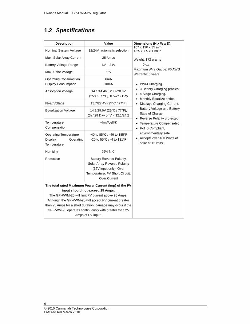
1.2 Specifications
Description Value
Nominal System Voltage 12/24V, automatic selection
Max. Solar Array Current 25 Amps
Battery Voltage Range 6V – 31V
Max. Solar Voltage 56V
Operating Consumption
Display Consumption
6mA
10mA
Absorption Voltage 14.1/14.4V 28.2/28.8V
(25°C / 77°F), 0.5-2h / Day
Float Voltage 13.7/27.4V (25°C / 77°F)
Equalization Voltage 14.8/29.6V (25°C / 77°F),
2h / 28 Day or V < 12.1/24.2
Temperature
Compensation
-4mV/cell*K
Operating Temperature
Display Operating
Temperature
-40 to 85°C / -40 to 185°F
-20 to 55°C / -4 to 131°F
Humidity 99% N.C.
Protection Battery Reverse Polarity,
Solar Array Reverse Polarity
(12V input only), Over
Temperature, PV Short Circuit,
Over Current
The total rated Maximum Power Current (Imp) of the PV
input should not exceed 25 Amps.
The GP-PWM-25 will limit PV current above 25 Amps.
Although the GP-PWM-25 will accept PV current greater
than 25 Amps for a short duration, damage may occur if the
GP-PWM-25 operates continuously with greater than 25
Amps of PV input.
Dimensions (H x W x D): 107 x 190 x 35 mm 4.25 x 7.5 x 1.38 in
Weight: 172 grams
6 oz
Maximum Wire Gauge: #6 AWG
Warranty: 5 years
PWM Charging.
3 Battery Charging profiles.
4 Stage Charging.
Monthly Equalize option.
Displays Charging Current,
Battery Voltage and Battery
State of Charge.
Reverse Polarity protected.
Temperature Compensated.
RoHS Compliant,
environmentally safe
Accepts over 400 Watts of
solar at 12 volts.
Owner’s Manual | GP-PWM-25 Regulator
7
© 2010 Carmanah Technologies Corporation Last revised March 2010
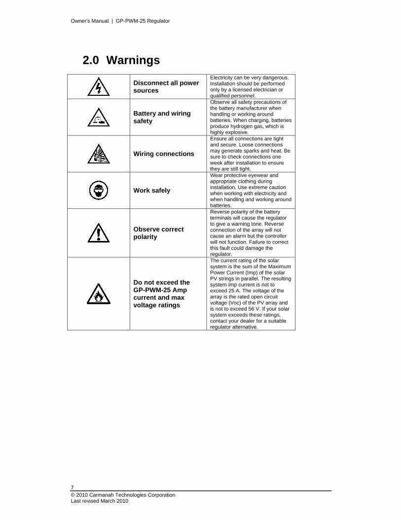
2.0 Warnings
Disconnect all power sources
Electricity can be very dangerous. Installation should be performed only by a licensed electrician or qualified personnel.
Battery and wiring safety
Observe all safety precautions of the battery manufacturer when handling or working around batteries. When charging, batteries produce hydrogen gas, which is highly explosive.
Wiring connections
Ensure all connections are tight and secure. Loose connections may generate sparks and heat. Be sure to check connections one week after installation to ensure they are still tight.
Work safely
Wear protective eyewear and appropriate clothing during installation. Use extreme caution when working with electricity and when handling and working around batteries.
Observe correct polarity
Reverse polarity of the battery terminals will cause the regulator to give a warning tone. Reverse connection of the array will not cause an alarm but the controller will not function. Failure to correct this fault could damage the regulator.
Do not exceed the GP-PWM-25 Amp current and max voltage ratings
The current rating of the solar system is the sum of the Maximum Power Current (Imp) of the solar PV strings in parallel. The resulting system Imp current is not to exceed 25 A. The voltage of the array is the rated open circuit voltage (Voc) of the PV array and is not to exceed 56 V. If your solar system exceeds these ratings, contact your dealer for a suitable regulator alternative.
Owner’s Manual | GP-PWM-25 Regulator
8
© 2010 Carmanah Technologies Corporation Last revised March 2010
3.0 Tools and Materials Needed
Drill with 3/32” and 3/8 bits UV Wire (Solar Array) to GP-PWM-25)*
Keyhole or Jigsaw Battery Wire (GP-PWM-25 to Battery)*
Phillips Screwdriver Wire Cutters Pencil or Marking Implement Wire Strippers Torque wrench (optional) Electrical Tape
If the GP-PWM-25 Regulator was purchased with a Go Power! RV Solar Power Kit then UV resistant wire is included. For instructions regarding the Go Power! RV Solar Power Kit installation, please refer to the Installation Guide provided with the Kit.
4.0 Choosing a Location The GP-PWM-25 is designed to be mounted flush against a wall, out of the way but easily visible. The GP-PWM-25 should be:
mounted as close to the battery as possible. mounted on a vertical surface to optimize cooling of the unit. indoors, protected from the weather.
In a RV, the most common regulator location is above the refrigerator. The wire from the solar array most commonly enters the RV through the fridge vent on the roof. PV connections should connect directly to the regulator. Positive and negative battery connections must connect directly from the regulator to the batteries. Use of a positive or negative distribution bus is allowed between the regulator and battery as long as it is properly sized, electrically safe and an adequate wire size is maintained.

Owner’s Manual | GP-PWM-25 Regulator
9
© 2010 Carmanah Technologies Corporation Last revised: March 2010
5.0 Installation Instructions
1. Prepare for mounting. Use the template provided at the end of the manual to mark the four mounting holes and the “cutting line for flush mounting.”
2. Complete the installation of the solar modules. If this GP-PWM-25 was
purchased as part of a Go Power! Solar Power Kit, follow the Installation Guide provided. Otherwise follow manufacturer’s instructions for solar module mounting and wiring.
3. Select wire type and gauge. If this GP-PWM-25 was purchased as part of a Go
Power! Solar Power Kit, appropriate wire type, gauge, and length is provided. Please continue to Section 6, “Operating Instructions.” If the GP-PWM-25 was purchased separately, follow the instructions included here.
Wire type is recommended to be a stranded copper UV resistant wire. Wire fatigue and the likelihood of a loose connection are greatly reduced in stranded wire compared to solid wire. Wire gauge should be able to sustain rated current as well as minimizing voltage drop. Suggested Minimum Wire Gauge (Cable length 25 ft max. from solar array to battery bank) 50 Watt #14 Wire Gauge 80 Watt #12 Wire Gauge 95 Watt #10 Wire Gauge 115 Watt #10 Wire Gauge 160 Watt #10 Wire Gauge 240 Watt #10 Wire Gauge Terminal Screw Torque 16 inch pounds (1.8N.m)
IMPORTANT: Identify the polarity (positive and negative) on the cable used for the battery and solar module. Use colored wires or mark the wire ends with tags. Although the GP-PWM-25 is protected, a reverse polarity contact may damage the unit.

Owner’s Manual | GP-PWM-25 Regulator
10
© 2010 Carmanah Technologies Corporation Last revised March 2010
4. Wiring the GP-PWM-25. Wire the GP-PWM-25 according to the wiring schematic in Section 11. Run wires from the solar array and the batteries to the location of the GP-PWM-25. Keep the solar array covered with an opaque material until all wiring is completed. Torque all terminal screws to 16 inch pounds (1.8N.m) Connect the battery wiring to the regulator first and then connect the battery wiring to the battery.
IMPORTANT: Always use appropriate circuit protection on any conductor attached to a battery.
With battery power attached, the regulator should power up and display information. Connect the solar wiring to the regulator and remove the opaque material from the solar array. The negative solar array and battery wiring must be connected directly to the regulator for proper operation. Do not connect the negative solar array or negative battery regulator wiring to the chassis of the vehicle.
5. Mounting the GP-PWM-25. Mount the GP-PWM-25 to the wall using the
included four mounting screws. Congratulations, your GP-PWM-25 should now be operational. If the battery power is low and the solar array is producing power, your battery should begin to charge.
6. Re-torque: After 30 days of operation re torque all terminal screws to ensure the wires are properly secured to the controller.

Owner’s Manual | GP-PWM-25 Regulator
11
© 2010 Carmanah Technologies Corporation Last revised: March 2010
6.0 Operating Instructions Power Up
When the GP-PWM-25 is connected to the battery, the GP-PWM-25 will go into Power Up mode. The controller will select the battery voltage automatically. If the battery voltage is above 20 Volts the controller assumes a 24 Volt battery system. Icons Displayed: Three horizontal dashes
Setting the Battery Type / Charging Profile
Set the Battery Type / Charging Profile by holding down the B Button for 10 seconds. When the display begins blinking you may set the Battery Type by toggling through the Charging Profile numbers 1, 2 or 3 by pressing the B Button.
Refer to the Battery Charge Profile Chart on the following page for details on each profile.

Owner’s Manual | GP-PWM-25 Regulator
12
© 2010 Carmanah Technologies Corporation Last revised March 2010
Confirm the Battery Type / Charging Profile selection by pressing the A Button.
Depending on the battery voltage when the GP-PWM-25 Power Up occurs, the GP-PWM-25 may do a Boost Charge or quickly go into Float Charge. The Charging Profile selected will commence the following day after a Power Up.
Battery Charge Profile Chart
Auto Equalize: The GP-WWM-25 has an automatic equalize feature that will charge and recondition your batteries once a month at a higher voltage to ensure that any excess sulfation is removed. This feature is recommended for Flooded batteries only. Check with
your battery manufacturer. NOTE: This feature is only available for Charging Profile 1.
Battery Type FLOODED AGM GEL
Charging Profile # 1 2 3
Float Charge @ 25°C: 13.7 / 27.4V
Bulk/Absorption Charge @ 25°C:
Applied for 30 min each morning 14.4 / 28.8V
14.1 / 28.2V
Boost Charge
Applied for 2 hours if the battery voltage drops below 12.3 volts.
14.4 / 28.8V 14.1 / 28.2V
Equalization Charge
Applied for 2 hours every 28 days and if the battery voltage drops below 12.1 volts.
14.8 / 29.6V N/A N/A
The Boost Charge will occur in addition to the Bulk Charge. The Equalization Charge will occur in addition to the Boost Charge.
If a charging cycle is unable to complete in a single day, it will continue the following day.
The terms FLOODED, AGM and GEL are generic battery designations. Choose the charging profile that works best with your battery manufacturer’s recommendations.

Owner’s Manual | GP-PWM-25 Regulator
13
© 2010 Carmanah Technologies Corporation Last revised: March 2010
Viewing the Regulator display information
To toggle between State of Charge (SOC), Battery Voltage and PV Charging Current, press the B Button.
The battery state of charge is shown as a percentage.
Icons Displayed: Battery, Percent Symbol
Push the B Button to show the battery voltage.
Icons Displayed: Battery, Volt Symbol (V)
Push the B Button to show the PV charging current. The GP-PWM-25 will begin to limit the current as the battery reaches a full charge.
Icons Displayed: Sun, Battery, Current Symbol (A)
Non volatile memory: Any settings made on the GP-PWM-25 will be saved even when the power has been disconnected from the regulator.
Errors Over Voltage
If the GP-PWM-25 experiences a battery over voltage (15.5 / 31V), the controller will stop operating and the display will begin to flash. The controller will resume operating when the error is cleared. Icons Displayed: Battery, Volt Symbol,
Lightning Bolt
Low Voltage
If the GP-PWM-25 experiences the battery state of charge reaching zero, a lightning bolt symbol will begin to flash in the lower right corner of the display. The regulator will continue operating. The regulator will only stop operating if the voltage drops below 6 volts.
Icons Displayed: Battery, Percent Symbol, Lightning Bolt

Owner’s Manual | GP-PWM-25 Regulator
14
© 2010 Carmanah Technologies Corporation Last revised March 2010
7.0 Before You Read Troubleshooting Before a problem is suspected with the system, read this section. There are numerous events that may appear as problems but are in fact perfectly normal. It seems like my flooded batteries are losing water over time. Flooded batteries may need to have distilled water added periodically to replace fluid loss during charging. Excessive water loss during a short period of time indicates the possibility of overcharging or aging batteries. When charging, my flooded batteries are emitting gas. During charging, hydrogen gas is generated within the battery. The gas bubbles stir the battery acid allowing it to receive a more full state of charge. Ensure they are in a well ventilated space. My voltmeter shows a different reading than the GP-PWM-25 display The meter value on the GP-PWM-25 display is an approximate reading intended for indication purposes only. There is an approximate 0.1 volt inherent error present that may be accentuated when compared with readings from another voltmeter. There may be a slight difference between the battery voltage displayed on the GP-PWM-25 display and the battery voltage measured at the battery terminals. When troubleshooting using a voltmeter, check both the battery voltage at the GP-PWM-25 battery terminals and battery voltage at the battery terminals. If a difference of more than 0.5 Volts is noted, this indicates a large voltage drop possibly caused by loose connections, long wire runs, small wire gauge, faulty wiring, a faulty voltmeter or all the above. Consult the Suggested Minimum Wire Gauge chart in Section 5 for wiring suggestions and check all connections.

Owner’s Manual | GP-PWM-25 Regulator
15
© 2010 Carmanah Technologies Corporation Last revised: March 2010
8.0 Troubleshooting Problems How to read this section Troubleshooting Problems is split into three sub-sections, grouped by symptoms involving key components. Components considered irrelevant in a diagnosis are denoted ‘Not Applicable’ (N/A). A multimeter or voltmeter may be required for some procedures listed. It is imperative all electrical precautions stated in the Warning Section and outlined in the Installation Section are followed. Even if it appears the system is not functioning, it should be treated as a fully functioning system generating live power.
8.1 Problems with the Display Display Reading: Blank Time of Day: Daytime/Nighttime Possible Cause: (1) Battery or fuse connection and/or solar array connection (Daytime only). (2) Battery or fuse connection (Nighttime only). How to tell: (1) Wake up the unit by pushing the A Button. (2) & (3) Check the voltage at the regulator battery terminals with a voltmeter and compare with a voltage reading at the battery terminals. If there is no voltage reading at the regulator battery terminals, the problem is in the wiring between the battery and the regulator. If the battery voltage is lower than 6 volts the regulator will not function. For the solar array, repeat steps 2 and 3 substituting all battery terminals with solar array terminals. Remedy: (2) & (3) Check all connections from the regulator to the battery including checking for correct wire polarity. Check that all connections are clean, tight, and secure. Ensure the battery voltage is above 6 volts.
8.2 Problems with Voltage Voltage Reading: Inaccurate Time of Day: Daytime/Nighttime Possible Cause: (1) Excessive voltage drop from batteries to regulator due to loose connections, small wire gauge or both. How to tell: (1) Check the voltage at the regulator battery terminals with a voltmeter and compare with the voltage reading
at the battery terminals. If there is a voltage discrepancy of more than 0.5 V, there is an excessive voltage drop.
Remedy: (1) Check all connections from the regulator to the battery including checking for correct wire polarity. Check
that all connections are clean, tight, and secure. Shorten the distance from the regulator to battery or obtain larger gauge wire. It is also possible to double up the existing gauge wire (i.e. two wire runs) to simulate a larger gauge wire.
Owner’s Manual | GP-PWM-25 Regulator
16
© 2010 Carmanah Technologies Corporation Last revised March 2010
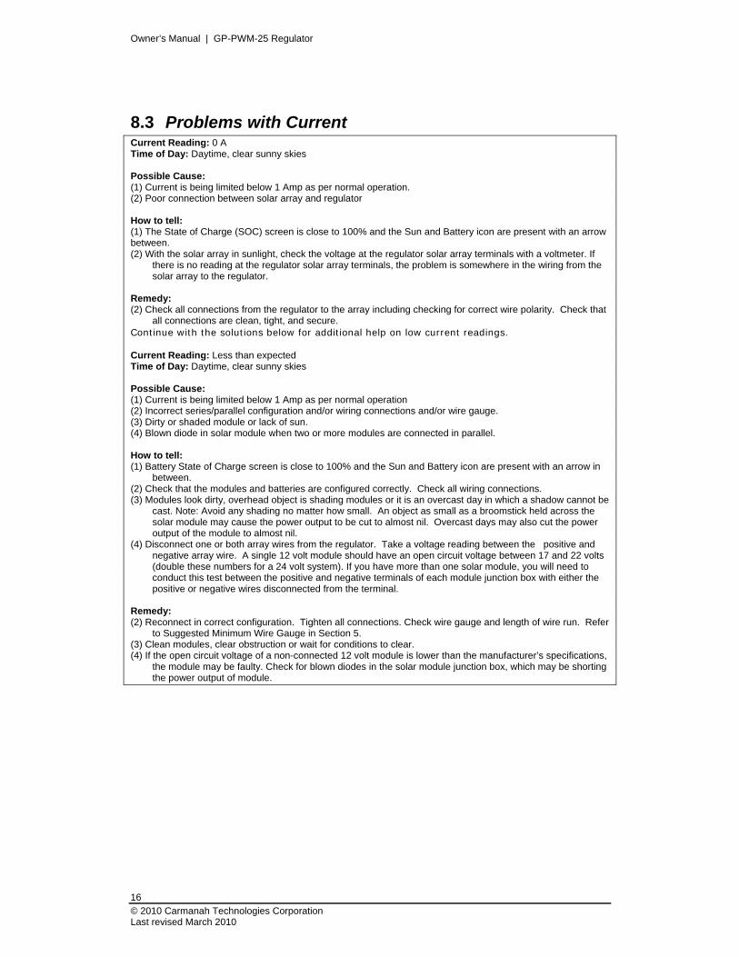
8.3 Problems with Current Current Reading: 0 A Time of Day: Daytime, clear sunny skies Possible Cause: (1) Current is being limited below 1 Amp as per normal operation. (2) Poor connection between solar array and regulator How to tell: (1) The State of Charge (SOC) screen is close to 100% and the Sun and Battery icon are present with an arrow between. (2) With the solar array in sunlight, check the voltage at the regulator solar array terminals with a voltmeter. If
there is no reading at the regulator solar array terminals, the problem is somewhere in the wiring from the solar array to the regulator.
Remedy: (2) Check all connections from the regulator to the array including checking for correct wire polarity. Check that
all connections are clean, tight, and secure. Continue with the solutions below for additional help on low current readings. Current Reading: Less than expected Time of Day: Daytime, clear sunny skies Possible Cause: (1) Current is being limited below 1 Amp as per normal operation (2) Incorrect series/parallel configuration and/or wiring connections and/or wire gauge. (3) Dirty or shaded module or lack of sun. (4) Blown diode in solar module when two or more modules are connected in parallel. How to tell: (1) Battery State of Charge screen is close to 100% and the Sun and Battery icon are present with an arrow in
between. (2) Check that the modules and batteries are configured correctly. Check all wiring connections. (3) Modules look dirty, overhead object is shading modules or it is an overcast day in which a shadow cannot be
cast. Note: Avoid any shading no matter how small. An object as small as a broomstick held across the solar module may cause the power output to be cut to almost nil. Overcast days may also cut the power output of the module to almost nil.
(4) Disconnect one or both array wires from the regulator. Take a voltage reading between the positive and negative array wire. A single 12 volt module should have an open circuit voltage between 17 and 22 volts (double these numbers for a 24 volt system). If you have more than one solar module, you will need to conduct this test between the positive and negative terminals of each module junction box with either the positive or negative wires disconnected from the terminal.
Remedy: (2) Reconnect in correct configuration. Tighten all connections. Check wire gauge and length of wire run. Refer
to Suggested Minimum Wire Gauge in Section 5. (3) Clean modules, clear obstruction or wait for conditions to clear. (4) If the open circuit voltage of a non-connected 12 volt module is lower than the manufacturer’s specifications,
the module may be faulty. Check for blown diodes in the solar module junction box, which may be shorting the power output of module.
Owner’s Manual | GP-PWM-25 Regulator
17
© 2010 Carmanah Technologies Corporation Last revised: March 2010
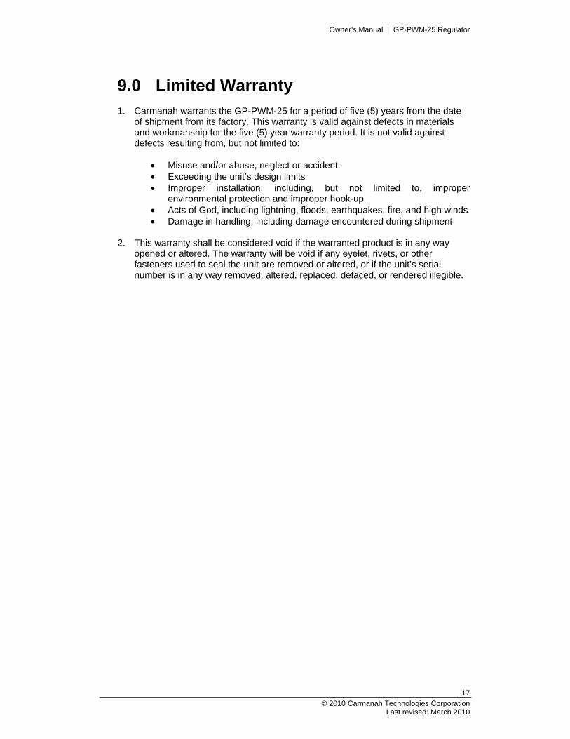
9.0 Limited Warranty
1. Carmanah warrants the GP-PWM-25 for a period of five (5) years from the date of shipment from its factory. This warranty is valid against defects in materials and workmanship for the five (5) year warranty period. It is not valid against defects resulting from, but not limited to:
Misuse and/or abuse, neglect or accident. Exceeding the unit’s design limits Improper installation, including, but not limited to, improper
environmental protection and improper hook-up Acts of God, including lightning, floods, earthquakes, fire, and high winds Damage in handling, including damage encountered during shipment
2. This warranty shall be considered void if the warranted product is in any way
opened or altered. The warranty will be void if any eyelet, rivets, or other fasteners used to seal the unit are removed or altered, or if the unit’s serial number is in any way removed, altered, replaced, defaced, or rendered illegible.

Owner’s Manual | GP-PWM-25 Regulator
18
© 2010 Carmanah Technologies Corporation Last revised March 2010
9.1 General Warranty Issues Please refer to the manufacturers’ warranty sheet(s).
1. Carmanah cannot assume responsibility for any damages to any system components used in conjunction with Carmanah products nor for claims for personal injury or property damage resulting from the use of Carmanah products or the improper operation thereof or consequential damages arising from the products or use of the products.
2. Carmanah cannot guarantee compatibility of its products with other components
used in conjunction with Carmanah products, including, but not limited to, solar modules, batteries, and system interconnects, and such loads as inverters, transmitters, and other loads which produce “noise” or electromagnetic interference, in excess of the levels to which Carmanah products are compatible.
3. Warranty repair and/or evaluation will be provided only at the Victoria, British
Columbia facility of Carmanah. Units for such repair and/or evaluation must be returned freight prepaid to Carmanah with a written description of any apparent defects. Carmanah will not be required at any time to visit the installation site wherein Carmanah products are subject to warranty repair and/or evaluation.
4. Only Carmanah is authorized to repair any of its products, and they reserve the
right to repair or replace any unit returned for warranty repair. The party returning a unit for repair is responsible for proper packaging and for shipping and insurance charges, as well as any other charges encountered, in shipping to and from Carmanah.
5. The purchaser’s exclusive remedy for any and all losses or damages resulting
from the date of sale of this product including, but not limited to, any allegations of breach of warranty, breach of contract, negligence or strict liability, shall be limited, at Carmanah option, to either the return of the purchase price or the replacement of the particular product for which claim is made and proved. In no event shall Carmanah be liable to purchaser or purchaser’s customers or to anyone else for any punitive, special, consequential, incidental or indirect losses or damages resulting from the sale of the product, whether based upon loss of goodwill, lost profits, work stoppages, impairments of other goods, breach of contract, or otherwise.
6. This warranty supersedes all other warranties and may only be modified by
statement in writing, signed by Carmanah.
7. Warranty terms effective as of January, 2009.
Owner’s Manual | GP-PWM-25 Regulator
19
© 2010 Carmanah Technologies Corporation Last revised: March 2010
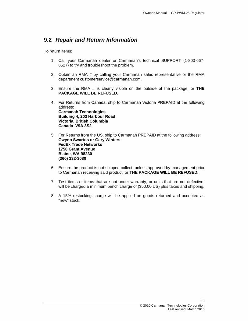
9.2 Repair and Return Information To return items:
1. Call your Carmanah dealer or Carmanah’s technical SUPPORT (1-800-667-6527) to try and troubleshoot the problem.
2. Obtain an RMA # by calling your Carmanah sales representative or the RMA
department [email protected].
3. Ensure the RMA # is clearly visible on the outside of the package, or THE PACKAGE WILL BE REFUSED.
4. For Returns from Canada, ship to Carmanah Victoria PREPAID at the following
address: Carmanah Technologies Building 4, 203 Harbour Road Victoria, British Columbia Canada V9A 3S2
5. For Returns from the US, ship to Carmanah PREPAID at the following address:
Gwynn Swartos or Gary Winters FedEx Trade Networks 1750 Grant Avenue Blaine, WA 98230 (360) 332-3080
6. Ensure the product is not shipped collect, unless approved by management prior
to Carmanah receiving said product, or THE PACKAGE WILL BE REFUSED. 7. Test items or items that are not under warranty, or units that are not defective,
will be charged a minimum bench charge of ($50.00 US) plus taxes and shipping. 8. A 15% restocking charge will be applied on goods returned and accepted as
“new” stock.
Owner’s Manual | GP-PWM-25 Regulator
20
© 2010 Carmanah Technologies Corporation Last revised March 2010
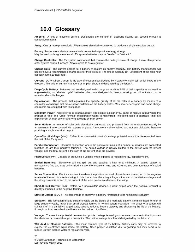
10.0 Glossary Ampere: A unit of electrical current. Designates the number of electrons flowing per second through a conductive material. Array: One or more photovoltaic (PV) modules electrically connected to produce a single electrical output. Battery: Two or more electrochemical cells connected to provide energy storage. May be used to designate one cell. PV system batteries may be “sealed” or “wet acid”. Charge Controller: The PV system component that controls the battery’s state of charge. It may also provide other system control functions. Also referred to as a regulator. Charge Rate: The current applied to a battery to restore its energy capacity. The battery manufacturer will usually have a recommended charge rate for their product. The rate is typically 10 –20 percent of the amp hour capacity at the 20-hour rate. Current: DC or Direct Current is the type of electron flow provided by a battery or solar cell, which flows in one direction. The unit for current is ampere or amp for short and designated by the letter A. Deep Cycle Battery: Batteries that are designed to discharge as much as 80% of their capacity as opposed to engine-starting or “shallow cycle” batteries which are designed for heavy cranking but will not stand up to repeated deep discharges. Equalization: The process that equalizes the specific gravity of all the cells in a battery by means of a controlled overcharge that breaks down sulfation on the battery plates. Most inverter/chargers and some charge controllers are equipped with this feature. Maximum Power: Also referred to as peak power. The point of a solar array, panel or module output where the product of “Imp” and “Vmp” (“Pmax”, measured in watts) is maximized. The points used to calculate Pmax are Imp (current @ max power) and Vmp (voltage @ max power). Solar Module: A number of solar cells electrically connected, and protected from the environment usually by an aluminum frame covered with a pane of glass. A module is self-contained and not sub dividable, therefore providing a single electrical output. Open-Circuit Voltage (Voc): Refers to a photovoltaic device’s voltage potential when it is disconnected from the rest of the PV system. Parallel Connection: Electrical connection where the positive terminals of a number of devices are connected together, as are their negative terminals. The output voltage is usually limited to the device with the lowest voltage, and the total current is the sum of the current of all the devices. Photovoltaic (PV): Capable of producing a voltage when exposed to radiant energy, especially light. Sealed Batteries: Electrolyte will not spill out and gassing is kept to a minimum. A sealed battery is maintenance free and may be installed in several orientations. GEL and AGM are two common types of sealed batteries. Series Connection: Electrical connection where the positive terminal of one device is attached to the negative terminal of the next in a series string; in this connection, the string voltage is the sum of the device voltages and the string current is limited to the current of the least productive device in the string. Short-Circuit Current (Isc): Refers to a photovoltaic device’s current output when the positive terminal is directly connected to the negative terminal. State of Charge (SOC): The percentage of energy in a battery referenced to its nominal full capacity. Sulfation: The formation of lead sulfate crystals on the plates of a lead-acid battery. Normally used to refer to large sulfate crystals, rather than small crystals formed in normal battery operation. The plates of a battery will sulfate if left in a partially charged state, causing reduced battery capacity and shortening the life of the battery. If caught in time, equalization will remove the buildup of sulfation. Voltage: The electrical potential between two points. Voltage is analogous to water pressure in that it pushes the electrons or current through a conductor. The unit for voltage is volt and designated by the letter V. Wet Acid or Flooded Batteries: The most common type of PV battery. Battery caps may be removed to expose the electrolyte liquid inside the battery. Need proper ventilation due to gassing and may need to be topped up with distilled water at regular intervals.

Owner’s Manual | GP-PWM-25 Regulator
21
© 2010 Carmanah Technologies Corporation Last revised: March 2010
11.0 Installation Template
Owner’s Manual | GP-PWM-25 Regulator
22
© 2010 Carmanah Technologies Corporation Last revised March 2010
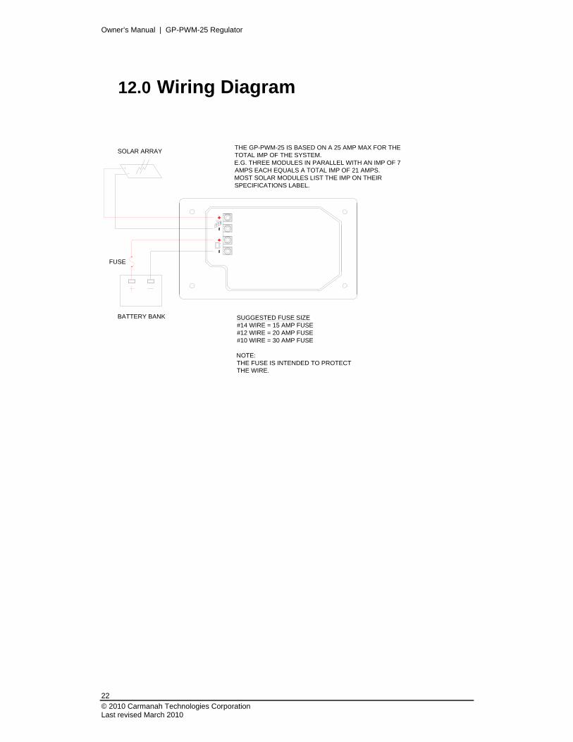
12.0 Wiring Diagram
SUGGESTED FUSE SIZE#14 WIRE = 15 AMP FUSE#12 WIRE = 20 AMP FUSE#10 WIRE = 30 AMP FUSE
NOTE:THE FUSE IS INTENDED TO PROTECTTHE WIRE.
THE GP-PWM-25 IS BASED ON A 25 AMP MAX FOR THETOTAL IMP OF THE SYSTEM.E.G. THREE MODULES IN PARALLEL WITH AN IMP OF 7AMPS EACH EQUALS A TOTAL IMP OF 21 AMPS.MOST SOLAR MODULES LIST THE IMP ON THEIRSPECIFICATIONS LABEL.
SOLAR ARRAY
BATTERY BANK
FUSE

Owner’s Manual | GP-PWM-25 Regulator
23
© 2010 Carmanah Technologies Corporation Last revised: March 2010
© 2010 Carmanah Technologies Corporation carmanah.com
Technical Support: [email protected]
Toll Free (US and Canada): 1-800-667-6527 Worldwide: 1-250-652-5233
Toll Free Fax (US and Canada): 1-866-607-6527
Number: 57175_MAN_GP-PWM-25 Regulator_RevE 8.5x11
57175