go-baby-go wild thing! abdulla almutairi aa3272@nau
TRANSCRIPT

1
Go-Baby-Go wild thing!
Prepared by:
Team Members: NAU Emails:
Ali Mohammad [email protected]
Abdulla Almutairi [email protected]
Ali Albaloushi [email protected]
Hakem Almutairi [email protected]
Project Sponsor:
● Electrical Engineering (EE) department.
● School of informatics, Computing & Cyber Systems(SICCS).
Project Clients:
● Dr. James "Cole" Galloway”
○ Professor, Dept. of Physical Therapy.
○ University of Delaware.
○ Founder of the project.
● Dr. Kyle Winfree
○ Assistant Professor
○ PhD,Biomechanics and Movement Science, University of Delaware.
○ MSE,Robotics, University of Pennsylvania.
○ BS,Physics, Northern Arizona University.
Project Mentor:
● Ashwija Korenda
○ PhD Student
○ Wireless Networking and Information Processing (WiNIP) laboratory.

2
Table of Content: Page Number
1. Introduction:…………………………………………………………………………3
2. Installation of
widget:………………………………………………………………………………..5
3. Maintenance:…………………………………………………………………………14
4. Troubleshooting
operation:……………………………………………………………………………..17
5. Conclusion:…………………………………………………………………………...19
6. Appendices with schematic or Journal
papers:………………………………………………………………………………...20
Table of Figures: Page Number
1. Figure 1…………………………………………………………………………….. 7
2. Figure 2…………………………………………………………………………….. 8
3. Figure 3……………………………………………………………………………...9
4. Figure 4……………………………………………………………………………...10
5. Figure 5……………………………………………………………………………...11
6. Figure 6……………………………………………………………………………...12
7. Figure 7……………………………………………………………………………...13
8. Figure 8……………………………………………………………………………...13
9. Figure 9……………………………………………………………………………...14
10. Figure 10…………………………………………………………………………….14
11. Figure 11…………………………………………………………………………….18
12. Figure 12…………………………………………………………………………….20
13. Figure 13…………………………………………………………………………….21
14. Figure 14…………………………………………………………………………….22
15. Figure 15…………………………………………………………………………….23

3
Introduction:
“GoBabyGo” is a an international movement to assist children with disabilities and
restricted movements that began in 2012 by Dr. James Cole Galloway at University of
Delaware. In addition, the project is about a car that helps children in various activities.
Furthermore, it’s mentioned in the project description that Children with limited mobility often
do not receive the much needed exposure to socialization to appropriately cognitively develop.
Existing research shows that enabling young children with self control of their own
environment can have meaningful impacts on the long term outcomes given such impairments as
cerebral palsy or muscular dystrophy. The GoBabyGo (GBG) project at the University of
Delaware has developed a set of Do it yourself (DIY) cars for families with children with
mobility restrictions. These cars have been designed on commercially available ride on toy car
platforms (like Power Wheels) and have been deployed worldwide by the the (GBG) team.
As for our main goal it was to design a gaming platform on top of the wild thing thus
allowing children with mobility issues to socialize and interact with their peers. Children with
mobility issues deserve the right to be equal with other kids, which means, equal opportunities.
As a result, our team got the inspiration for the project from Mario Kart, rocket league and the
function of the pinball flippers The Mario Kart and rocket league gave us the idea of allowing
the children with mobility issues to play kickball/soccer games by using the car. As for the
pinball inspiration, it allowed us to add the flippers to the car which are attached to the motor
thus being controlled accordingly by a switch.
The wild thing has a unique set of subsystems and each one serves a unique task. So as
mentioned before we got the inspiration from the pinball flipper function and video games such
as Mario Kart and Rocket league. In order to allow them to play kickball/soccer, we have the
following subsystems:
Pinball design subsystem:
● Linear Motor
○ It has back and forward movement
○ It will act as a force thus pushing the flippers
● Flippers
○ Paddles
○ It will kick the ball
Mechanical part:
● Screws/Washers

4
○ Type of fastener made from metal plate used to distributed the load
○ It will allow connections between all parts and subsystems
● Punched Square tube zink plated
○ It’s a square hollow tube made of steel with holes punched in regular
intervals.
○ It can telescoped inside other sizes to add adjustable height put the 1 in
● Drilling
○ It’s a machine that drill holes to allow screws to be attached accordingly
○ To make holes on the provided PVC pipes to connect everything together
with screws.
Software Part:
● Arduino Microprocessor.
○ Allowing the connection between the hardware.
● L298 H-Bridge.
○ It controls the direction of the motor as desired.
● Switch:
○ It gives the signal to power the linear motor.
As mentioned before the goal of the project was to implement a real world game on the
wild thing car. Also, the team wanted to allow children with mobility issues to interact and play
with their peers thus our solution was to implement the pinball flipper on the wild thing to allow
them to play kickball/soccer. Since the team did multiple designs and had backup designs but
some of them were not at the required level that the team wanted to meet. For example,
implementing the brushless motors into the wild thing car didn’t work because the tires to kick
the ball were either small or big compared to the ball. As for the shovel design it didn’t work as
expected since the shovel didn’t provide much force. However, the team went back to the
flippers design but this time the team implemented a solid mechanical structure thus keeping the
flippers and the two motors attached firmly. This solid structure will allow the flippers to kick
the ball without risking damage to the structure or the motors.
The team believes that this design is innovative and complete since it delivered the
required goal of kicking the ball and it looks like it was taken from a video game. Finally, this
design allowed the team to understand that the problem of how children with mobility issues
can’t do simple things such as running or kicking but with this design it will allow them to do
such things.

5
Installation of widget:
The team considered these parts for the installation of the widget.
● 12V Battery:
○ to run the linear motor which will be connected to the L298 H-Bridge.
○ Two batteries with 12V connected in series in order to approach 24V, because we
couldn’t find a battery with 24V itself.
● L298 Dual H-Bridge:
○ Will be used to control the direction of the motor which will be adjusted by the
Arduino Code.
○ Maximum operating voltage of 46V.
○ Peak output current per channel
■ 2A.
○ Minimum logic voltage
■ 4.5V.
○ Maximum logic voltage
■ 7V.
● 4 Metal bars to attach the linear motor, and the flippers:
○ We used 2 metal bars that are connected from the car itself and it’s extended to
the front of the car to allow some space.
○ Punched Square tube zinc plated
■ Are attached to the extended bars to hold the flippers and the linear
motor.
● Linear motor:
○ We have two linear motors that are attached in the sides of the car.
○ Linear motor is heavy, for that we are holding it with the metal bars attached to
give it stability.
○ Maximum operating voltage
■ 24 V.
○ Minimum operating voltage
■ 12 V.
○ Maximum operating power
■ 1.8 W.
○ Minimum operating power
■ 33.6 W.

6
○ Maximum rated torque
■ 12.5 kg.cm.
○ Minimum rated torque
■ 0.06 kg.cm.
○ Continues working time
■ 24 hours.
○ Stroke: 30mm, 50mm and 70mm.
○ Maximum load current
■ 1.7A.
○ Minimum load current
■ 0.07A.
○ Maximum no-load speed
■ 470 rpm.
○ Minimum no-load speed
■ 3 rpm.
● Flippers
○ We made two flippers using PVC pipes and we filled the center of the flippers
with two pieces of wood in each flipper to allow the attachment of the linear
motor thus pushing the flippers and kick the ball.
● Set and reset switches
○ We have two switches, one switch is to turn on the linear motor thus kicking the
ball and this switch will be attached on the right controller of the car to make it
easy for the kid to use.
○ The second switch will be held on the linear motor so when the the flippers turn
back to its original position it will hit the reset switch and the linear motor will
stop working.
● Screws, washers, and nuts
○ Used 2 long screws for the flippers to allow the movement for kicking.
○ Used 10 medium long screws to hold the metal bars. And
○ Used 8 small screws to hold the linear motor into the metal bars.
○ Washers and nuts are used for all the screws to tighten all parts together and make
it strong.
The team have installed two switches one is to operate the motors while the second
switch is to reset the motor to its original position. One switch will be on the control paddle of
the wild thing; meanwhile, the other switch will be attached below on one of the motors. When
7
the switch goes backward it will hit the switch thus triggering the restart operation; as a result,
the motor will not go forward until the user hits the on switch which is on the controlling paddle.
The two switches are connected to the arduino and through the use of the L298 H-Bridge we can
control the position of the motor accordingly. Finally, in order to make the car to work the user
must sit on the car thus activating the sensors that are built in the wild thing itself under the seat
thus going to the direction that is desired by the user.
Steps for installation:
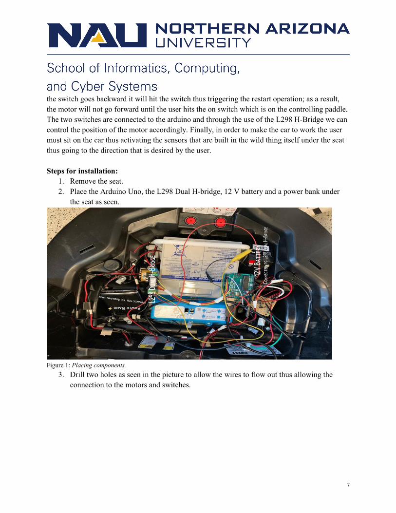
1. Remove the seat.
2. Place the Arduino Uno, the L298 Dual H-bridge, 12 V battery and a power bank under
the seat as seen.
Figure 1: Placing components.
3. Drill two holes as seen in the picture to allow the wires to flow out thus allowing the
connection to the motors and switches.

8
Figure 2 : Drilling on the Wild Thing from the front.
4. Drill three holes as seen in the picture to allow metal bars to be attached and attach
screws on them.

9
Figure 3 : Drilling on the Wild Thing from the bottom.
5. Drill holes on metal bars to allow the connection between the metal bars and punched
square tube zinc plated bar then attach screws as seen in the picture.

10
Figure 4 : Drilling on metal bars & attaching them on punched square tube zinc plated.
6. Attach flippers on to the punched square tube zinc plated as seen in the picture.

11
Figure 5 : Placement of Flippers.
7. Attach motors on to the punched square tube zinc plated as seen in the picture.

12
Figure 6 : Placement of Linear Motor.
8. Attach one switch on the control panel and the other on one of the motors and use glue to
make it firmly attached.

13
Figure 7 : Switch placement on control panel.
Figure 8 : Switch Placement on Linear Motor.
9. Attach a screw on the motor to allow the switch to be pressed when the motor return to its
original position as seen in the picture in above.
10. Connect the Arduino Uno to the battery power bank.

14
Figure 9 : Connecting Arduino Uno to a power supply.
11. Connect the L298 Dual H-bridge with the motors and the 12 V battery.
Figure 10: Connection on L298 Dual H-Bridge, Linear Motor wires &
battery.
12. Finally place the seat back.
Maintenance:
As for maintenance we believe that this product needs to be checked once every 5 months.
● Flippers:

15
○ PVC update.
○ Wood update.
● Seat cushion:
○ needs to be updated as soon as a rupture appears.
● DIY Reciprocating motor:
○ Needs to be updated if one of the connecting wires got seperated due to:
■ The ball hitting the wires.
■ The wires went below the tires of the car.
■ When a rupture appears on the wire it self.
○ If 24V is exceeded the motor will burn out and needs to be changed immediately.
● Tires:
○ Needs oil change to lubricate moving parts.
○ Change screws if needed.
● Punched Square tube zinc plated:
○ If the metal is exposed to water, rain and extreme weather the zinc coating will
corrode thus a replacement is needed.
○ Replace by removing the screws and washers and adding the new one.
● Switches: ○ Should be checked for corrosion at terminals which can be seen visually.
Part Image Market(Retail) Price
Flippers
1. PVC
2. Wood
Home Depot 1. $3.97
2. $1.67

16
Portable Child seat
Amazon $39.96
DIY Reciprocating
motor package
Aliexpress $126.79
L298 Dual H-Bridge
SparkFun Electronics $34.95
Arduino Uno
Microcontroller
Arduino Uno website $22.0
Momentary-On
Push Button Switch
Home Depot $3.00
Punched Square
tube zinc plated
Home Depot $17.98
17
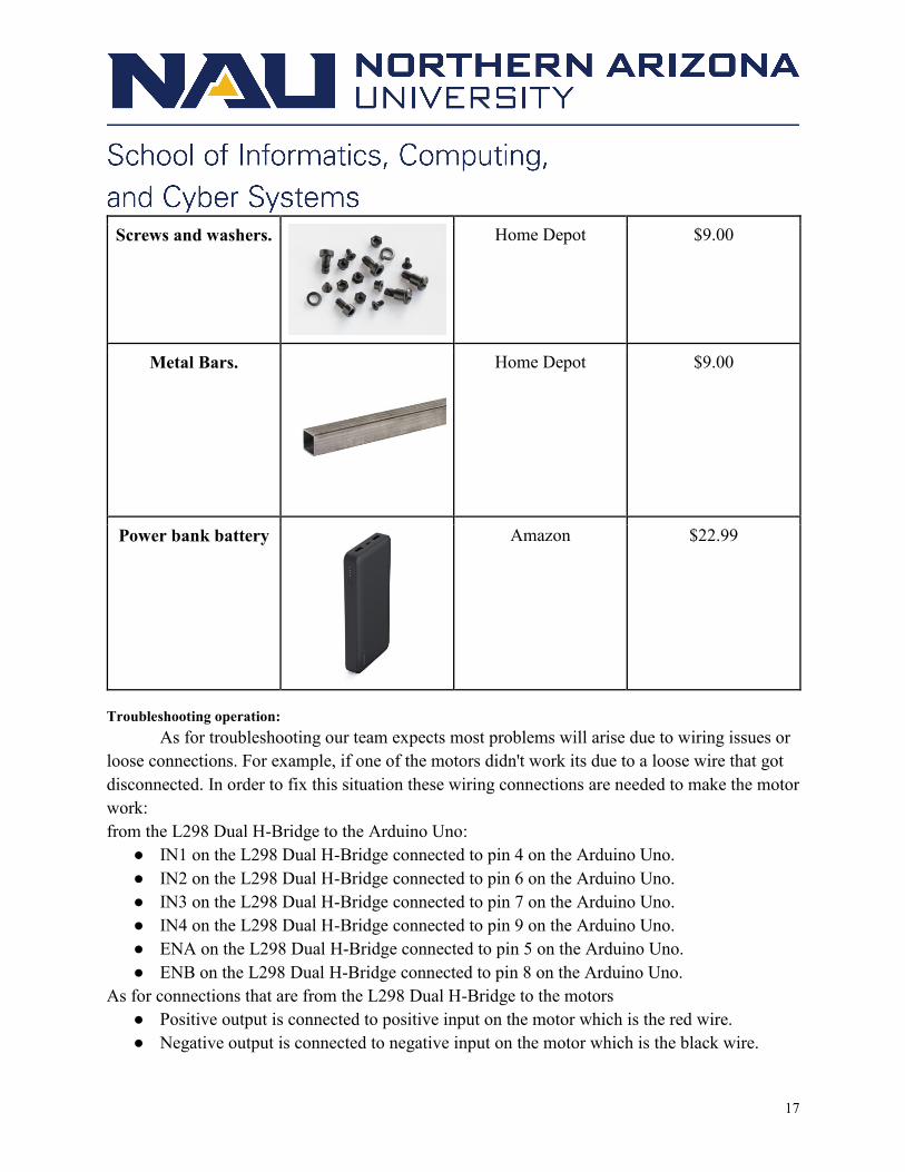
Screws and washers.
Home Depot $9.00
Metal Bars.
Home Depot $9.00
Power bank battery
Amazon $22.99
Troubleshooting operation:
As for troubleshooting our team expects most problems will arise due to wiring issues or
loose connections. For example, if one of the motors didn't work its due to a loose wire that got
disconnected. In order to fix this situation these wiring connections are needed to make the motor
work:
from the L298 Dual H-Bridge to the Arduino Uno:
● IN1 on the L298 Dual H-Bridge connected to pin 4 on the Arduino Uno.
● IN2 on the L298 Dual H-Bridge connected to pin 6 on the Arduino Uno.
● IN3 on the L298 Dual H-Bridge connected to pin 7 on the Arduino Uno.
● IN4 on the L298 Dual H-Bridge connected to pin 9 on the Arduino Uno.
● ENA on the L298 Dual H-Bridge connected to pin 5 on the Arduino Uno.
● ENB on the L298 Dual H-Bridge connected to pin 8 on the Arduino Uno.
As for connections that are from the L298 Dual H-Bridge to the motors
● Positive output is connected to positive input on the motor which is the red wire.
● Negative output is connected to negative input on the motor which is the black wire.

18
Figure 11 : L298 Dual H-Bridge output/input scheme.
Another problem the user might face which is the reset of the Arduino Uno for this case
the user need to connect the Arduino Uno to a computer and upload the code (which can be seen
in figure 15) on the Arduino Uno microcontroller and follow the wiring connection that are
mentioned earlier.
● (Needs Arduino software which can be downloaded from there website for free:
○ https://www.arduino.cc/en/Main/Software)
Finally, the last problems that needs troubleshooting that the user might face are the
power bank and the 12 battery running out of power. As a result the user can either recharge
them or replace them.
Conclusion:

19
In conclusion, this project allowed us to learn many different aspects about teamwork and
how to divide the workload equally. Furthermore, the main idea of the project was to design a
gaming platform on top of the existing car; as a result, we chose kickball/soccer. Thus allowing
children with mobility issues to play and interact with their peers. This project also allowed us to
learn more about the Arduino Uno and the L298 H-Bridge which was crucial to make our project
succeed.
Finally, we wish our clients to have wonderful years to come. We really enjoyed working
on this project because we would like to see children with mobility issues to take control of their
domain. Also, it would be nice to see the joy of their faces while they are interacting with their
peers. The Go Baby Go(GBG) team:
● Ali Mohammad ([email protected]).
● Ali Albaloushi ([email protected])
● Abdulla Almutairi ([email protected])
● Hakem Almutairi ([email protected]),
would like to thank the clients for allowing us to work on this project. While we are all
moving on to professional careers, we would be happy to answer short questions in the coming
months to help you get the product deployed and operating optimally in your organization.

20
Appendices with schematic or Journal papers:
Figure 12 : Mind map.

21
Figure 13 : Project Flow chart

22
Figure 14 : Circuit Schematic between Arduino Uno & L298 Dual H-Bridge.

23
Figure 15 : The source code for the H-Bridge to function
accordingly with the switches.