gnss quick starts3.microsurvey.com.s3.amazonaws.com/support/knowledgebase/fieldgenius... · choose...
TRANSCRIPT

Contents
GNSS Quick Start
Reference Guide for FieldGenius GNSS Rover setup and workflows.
MicroSurvey
FieldGenius 9

Contents
Page 1 of 27
MicroSurvey and FieldGenius are registered with the U.S. Patent and Trademark Office by MicroSurvey Software Inc. © 2017 MicroSurvey Software Inc.
Contents Part 1 - Create a New Project ............................................................................................................................ 3
Project Settings .............................................................................................................................................. 3
Units and Scale .......................................................................................................................................... 4
Coordinate System ..................................................................................................................................... 5
Project Files ................................................................................................................................................ 7
Project Information ..................................................................................................................................... 8
Part 2 – First Time Rover Setup ........................................................................................................................ 9
Create Instrument Connection Profile (Rover) ................................................................................................ 9
Model and Communication ....................................................................................................................... 10
Tolerance Settings Concepts .................................................................................................................... 11
Tolerance Setting: [Autonomous] / [RTK Float] / [RTK Fixed] ................................................................... 11
Active Tolerance ....................................................................................................................................... 11
Antenna Height ......................................................................................................................................... 12
Auto Recording ......................................................................................................................................... 12
Part 3 - Connect and Configure Correction Link .............................................................................................. 13
Connect to Instrument .................................................................................................................................. 13
Configure Correction Link ............................................................................................................................ 13
Device Settings ........................................................................................................................................ 13
Correction Data Settings........................................................................................................................... 13
RTCM Transformation Settings ................................................................................................................ 13
Part 4 – Program Options and Interface .......................................................................................................... 14
Configuring Program Options ....................................................................................................................... 14
Interface Options ...................................................................................................................................... 14
User Input Options .................................................................................................................................... 14
Point Attributes Options ............................................................................................................................ 15
Map Configurations Options ..................................................................................................................... 16
GNSS Options .......................................................................................................................................... 17
Staking Options ........................................................................................................................................ 18
Toolbars ....................................................................................................................................................... 19
Display Toolbar ........................................................................................................................................ 19
Observation Toolbar ................................................................................................................................. 19
GNSS Instrument Toolbar ........................................................................................................................ 19
Topo Toolbar ............................................................................................................................................ 20
Mini Toolbar .............................................................................................................................................. 20

Contents
Page 2 of 27
MicroSurvey and FieldGenius are registered with the U.S. Patent and Trademark Office by MicroSurvey Software Inc. © 2017 MicroSurvey Software Inc.
Map Select Toolbar .................................................................................................................................. 20
Point Toolbar ............................................................................................................................................ 20
Line Toolbar ............................................................................................................................................. 20
Part 5 - Measure Modes and Workflows .......................................................................................................... 21
Standard Measurement ................................................................................................................................ 21
Measurement Procedure Overview .......................................................................................................... 22
Offset Measurement..................................................................................................................................... 23
Point Staking ................................................................................................................................................ 25
Selecting a Point to Stake ......................................................................................................................... 25
Point Staking Screen ................................................................................................................................ 26
Staking Interface ...................................................................................................................................... 26
Point Staking Results ............................................................................................................................... 26
Appendix ......................................................................................................................................................... 27
Online Manual .............................................................................................................................................. 27
Movies ......................................................................................................................................................... 27
Helpdesk ...................................................................................................................................................... 27
Geoid Models ............................................................................................................................................... 27
Grid Shift Files ............................................................................................................................................. 27
Tutorials ....................................................................................................................................................... 27
Automap Libraries ........................................................................................................................................ 27
Feature Files ................................................................................................................................................ 27

Part 1 – Create a New Project
Page 3 of 27
MicroSurvey and FieldGenius are registered with the U.S. Patent and Trademark Office by MicroSurvey Software Inc. © 2017 MicroSurvey Software Inc.
Part 1 - Create a New Project The Project Manager in FieldGenius is used to open, create, and delete projects.
Create a New Project
• From the Project Manager choose “New
Project”
Configure New Project
• Enter a name for your project
• Review the Project Settings
• Modify the Project Settings if required
Project Settings A FieldGenius project is created with some default settings.
It is important to set the defaults to suit your most frequent
requirements. These defaults typically will only need to be
configured once.

Part 1 – Create a New Project
Page 4 of 27
MicroSurvey and FieldGenius are registered with the U.S. Patent and Trademark Office by MicroSurvey Software Inc. © 2017 MicroSurvey Software Inc.
Units and Scale The Distance and Angle Unit must be set when a project is
created, and cannot be modified once created.
Distance Unit Choose from Meters, International Feet, or US Survey Feet.
Distance Format
Choose from Decimal or Fractional format if the distance
unit is set to International Feet or US Survey Feet. Meters
are always decimal.
Distance Precision Choose distance precision for decimal format.
Angle Unit Choose from Degrees, Gons, or Radians.
Angle Format
Choose from DDD°MM’SSs”, DDD°MM.m’ or DDD.d° format if the angle unit is set to Degrees. Gons and
Radians are always decimal.
Angle Precision Choose angle display precision.
Direction Format Choose from North Azimuth, South Azimuth or Bearing for direction input/output format.
Scale Factor The Scale Factor value is applied to:
- Distances measured with a Total Station to compute scaled coordinates. Raw values are not affected.
- Distances entered for COGO calculations.
- Distances computed from COGO calculations, the inverse of the scale factor is applied.
Use the Save As Default option to permanently set the current settings as default values for future projects.

Part 1 – Create a New Project
Page 5 of 27
MicroSurvey and FieldGenius are registered with the U.S. Patent and Trademark Office by MicroSurvey Software Inc. © 2017 MicroSurvey Software Inc.
Coordinate System Coordinate system settings can be modified after a project
is created, however setting the most suitable default
eliminates the need to change it for each project.
Horizontal System Choose the horizontal projected coordinate system for your
project from a list of coordinate systems.
Use the Edit List option to add or remove coordinate
systems from the list of favourites. Use the steps outlined
below to add a coordinate system to the list.
Vertical System Choose the vertical datum for your project from a list of
available options. The list will always contain Ellipsoidal
(WGS84) and all available geoid models. See the Appendix for more information about Geoid Models.
Use the Save As Default option to permanently set the current settings as default values for future projects.
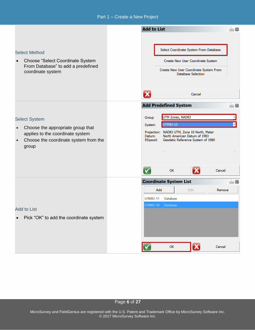
Add Coordinate System to List Pick Edit List to edit the Coordinate System list, then:
Add New Coordinate System
• From the Coordinate System List
choose “Add”
Part 1 – Create a New Project
Page 6 of 27
MicroSurvey and FieldGenius are registered with the U.S. Patent and Trademark Office by MicroSurvey Software Inc. © 2017 MicroSurvey Software Inc.
Select Method
• Choose “Select Coordinate System
From Database” to add a predefined
coordinate system
Select System
• Choose the appropriate group that
applies to the coordinate system
• Choose the coordinate system from the
group
Add to List
• Pick “OK” to add the coordinate system
Part 1 – Create a New Project
Page 7 of 27
MicroSurvey and FieldGenius are registered with the U.S. Patent and Trademark Office by MicroSurvey Software Inc. © 2017 MicroSurvey Software Inc.
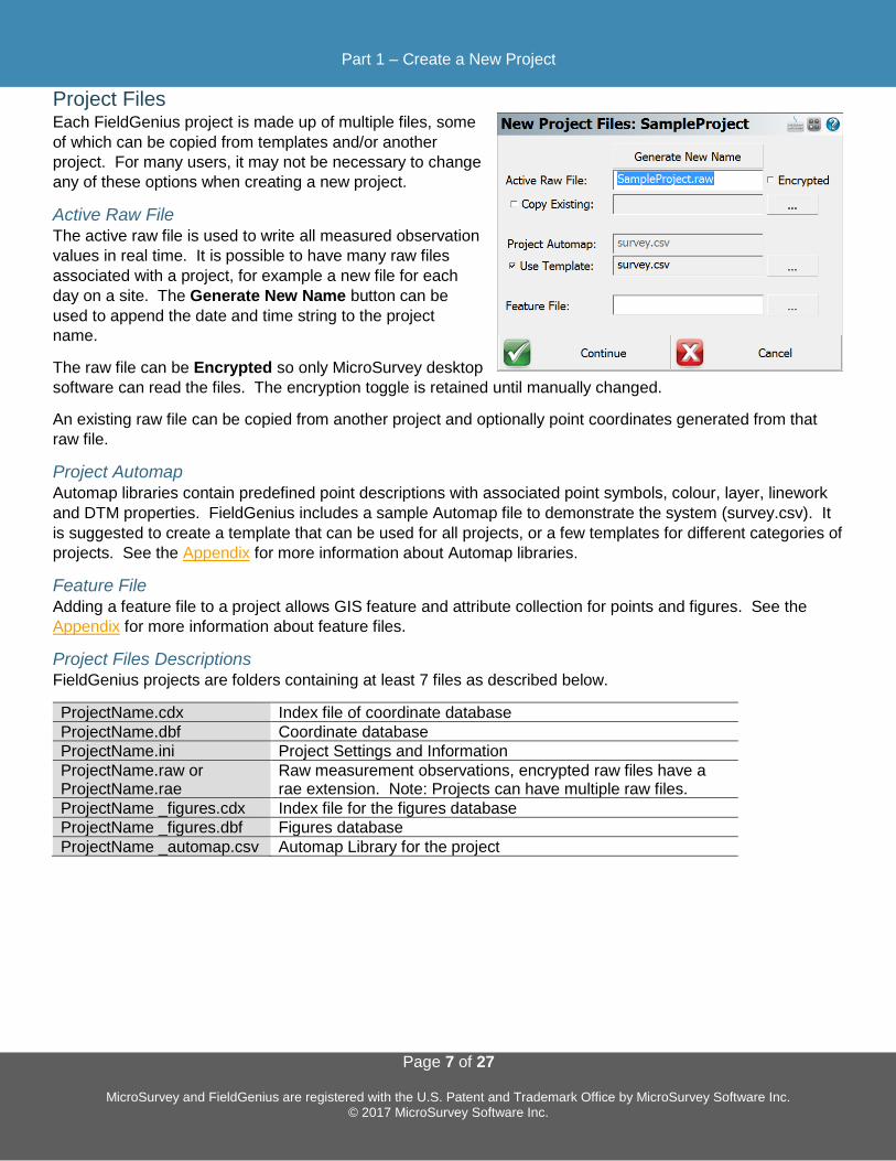
Project Files Each FieldGenius project is made up of multiple files, some
of which can be copied from templates and/or another
project. For many users, it may not be necessary to change
any of these options when creating a new project.
Active Raw File The active raw file is used to write all measured observation
values in real time. It is possible to have many raw files
associated with a project, for example a new file for each
day on a site. The Generate New Name button can be
used to append the date and time string to the project
name.
The raw file can be Encrypted so only MicroSurvey desktop
software can read the files. The encryption toggle is retained until manually changed.
An existing raw file can be copied from another project and optionally point coordinates generated from that
raw file.
Project Automap
Automap libraries contain predefined point descriptions with associated point symbols, colour, layer, linework
and DTM properties. FieldGenius includes a sample Automap file to demonstrate the system (survey.csv). It
is suggested to create a template that can be used for all projects, or a few templates for different categories of
projects. See the Appendix for more information about Automap libraries.
Feature File
Adding a feature file to a project allows GIS feature and attribute collection for points and figures. See the
Appendix for more information about feature files.
Project Files Descriptions FieldGenius projects are folders containing at least 7 files as described below.
ProjectName.cdx Index file of coordinate database
ProjectName.dbf Coordinate database
ProjectName.ini Project Settings and Information
ProjectName.raw or ProjectName.rae
Raw measurement observations, encrypted raw files have a rae extension. Note: Projects can have multiple raw files.
ProjectName _figures.cdx Index file for the figures database
ProjectName _figures.dbf Figures database
ProjectName _automap.csv Automap Library for the project
Part 1 – Create a New Project
Page 8 of 27
MicroSurvey and FieldGenius are registered with the U.S. Patent and Trademark Office by MicroSurvey Software Inc. © 2017 MicroSurvey Software Inc.
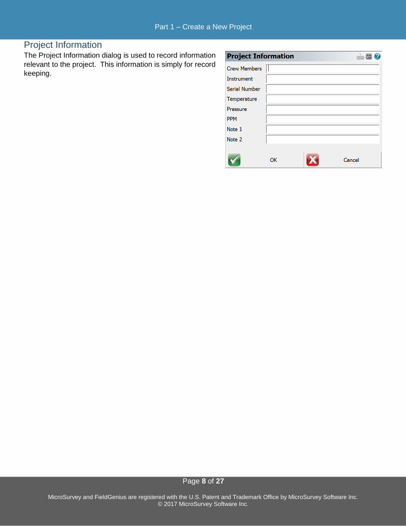
Project Information The Project Information dialog is used to record information
relevant to the project. This information is simply for record
keeping.

Part 2 – First Time Rover Setup
Page 9 of 27
MicroSurvey and FieldGenius are registered with the U.S. Patent and Trademark Office by MicroSurvey Software Inc. © 2017 MicroSurvey Software Inc.
Part 2 – First Time Rover Setup FieldGenius instrument profiles contain settings specific to each instrument. When selecting an instrument
profile and connecting to the instrument, all these settings are automatically inherited.
Create Instrument Connection Profile (Rover) To create a new GNSS Rover profile:
Add a New Profile
• From the Instrument Selection dialog
pick the GNSS Rover instrument type
• Pick “Add” to create a new profile
Enter Name and Save
• Enter a name for your profile
• Pick “Save”
Edit Profile
• With the new instrument profile
selected, pick “Edit” to edit the profile

Part 2 – First Time Rover Setup
Page 10 of 27
MicroSurvey and FieldGenius are registered with the U.S. Patent and Trademark Office by MicroSurvey Software Inc. © 2017 MicroSurvey Software Inc.
Profile Setup
• Choose the profile component to
configure
Model and Communication The main component of the instrument profile is the
instrument driver itself, which is specified by picking the
make and model of the device.
1. Pick the Make from the list
2. Pick the Model from the list
3. Choose the connection Port
4. Open the Bluetooth Device List and search for the
Bluetooth device
5. Ensure the new Device is selected
6. Pick Close to configure other components of the
profile, the selections will be saved on Close

Part 2 – First Time Rover Setup
Page 11 of 27
MicroSurvey and FieldGenius are registered with the U.S. Patent and Trademark Office by MicroSurvey Software Inc. © 2017 MicroSurvey Software Inc.
Tolerance Settings Concepts FieldGenius can be configured with three tolerance settings that determine the minimum requirements that
must be met for storing a position when the tolerance setting is active. The user can change the active
tolerance setting to suit the conditions and/or actions.
Tolerance Setting: [Autonomous] / [RTK Float] / [RTK Fixed] The three tolerance settings each have a default description
and various options configured for specific conditions. The
available options may vary between GNSS receivers.
Real Time Settings
Configure the minimum requirements for real time
positioning.
Post Process Settings
Configure Raw Data Logging settings based on satellite
availability.
Action Settings
Configure tolerance override ability, automatic skipping of
statistics screen, and automatic point storing.
Active Tolerance The active tolerance is used when measuring points to
determine if minimum requirements are met and which
actions will take place. It is a method of ensuring quality
standards are met.

Part 2 – First Time Rover Setup
Page 12 of 27
MicroSurvey and FieldGenius are registered with the U.S. Patent and Trademark Office by MicroSurvey Software Inc. © 2017 MicroSurvey Software Inc.
Antenna Height The antenna height dialog allows the user to change the
measured height of the receiver, and specifics about the
receiver:
Model The preconfigured offsets information of the receiver is
stored under the model name, pick “User Defined” to
manually enter the offset values.
Measure Point Available options vary between receivers.
Offsets Generally, the preconfigured or user-definable values are
displayed, for some receivers this information is provided by the firmware once connected.
Auto Recording Auto recording settings are stored for each instrument
profile.
Auto recording intervals can be set by distance or time.
These settings will automatically be used with the Auto
Record measure mode.

Part 3 – Connect and Configure Correction Link
Page 13 of 27
MicroSurvey and FieldGenius are registered with the U.S. Patent and Trademark Office by MicroSurvey Software Inc. © 2017 MicroSurvey Software Inc.
Part 3 - Connect and Configure Correction Link Connect to Instrument To connect to an instrument, pick the predefined profile and
choose “Connect”.
Configure Correction Link When connecting to a GNSS Rover device, the Link
Configure dialog will be displayed following successful
connection. Available options will vary depending on the
device type selected.
Device Settings
Device Type
Select the appropriate Correction Link device type, such as
GSM Module, UHF Radio Module, Data Collector Internet,
or Other Device.
Device Port Select the appropriate Port when multiple options exist.
Device Setup Setup the parameters for the Radio or Modem connection.
For radio corrections, choose the radio make and model from the pull-down and set the channel or frequency,
the radio will be programmed by FieldGenius to the channel or frequency selected (on some models).
For NTRIP or Network corrections, enter your internet and server credentials here.
Correction Data Settings
Message Type The message type is used in determining what data streams are sent from the reference station to the rover.
They can be RTCM, CMR or a proprietary format.
RTCM Transformation Settings To receive horizontal and vertical coordinate system information from your network, enable RTCM
Transformation messages.

Part 4 – Program Options and Interface
Page 14 of 27
MicroSurvey and FieldGenius are registered with the U.S. Patent and Trademark Office by MicroSurvey Software Inc. © 2017 MicroSurvey Software Inc.
Part 4 – Program Options and Interface Configuring Program Options Program options are designed to help the user get the most out of FieldGenius. Options relevant to GNSS
workflows are summarized. Program Options are accessed through:
MAIN MENU – Settings – Options
Interface Options
Map Colour Set the background of the map screen to white or black.
Map Orientation Set map orientation North or South.
Arc Resolution Set the number of segments for drawing arcs on the map.
Text Size (Info/Grid) Set the size of text displayed on information screens.
Show Scale Bar Toggle Scale Bar display on the map screen.
Scrollbar Width On some devices, it is possible to change the width of scrollbars to improve touch experience.
User Input Options
Keypad Text Colour Set the colour of the text on the virtual keypad.
KeyPad Background Colour Set the colour of the background on the virtual keypad.
Extended Edit Boxes
Set behaviour of the virtual keypad popping up.
Recommended settings are Single Click for devices without
a keyboard, Double Click for devices with a keyboard.
Menu Shortcuts
Toggle display of menu shortcuts for faster navigation with a
keyboard.
Instrument Toolbar Toggle which side of the screen the instrument toolbar will be displayed on. Left-handed users may prefer the
left side of the screen.
Part 4 – Program Options and Interface
Page 15 of 27
MicroSurvey and FieldGenius are registered with the U.S. Patent and Trademark Office by MicroSurvey Software Inc. © 2017 MicroSurvey Software Inc.
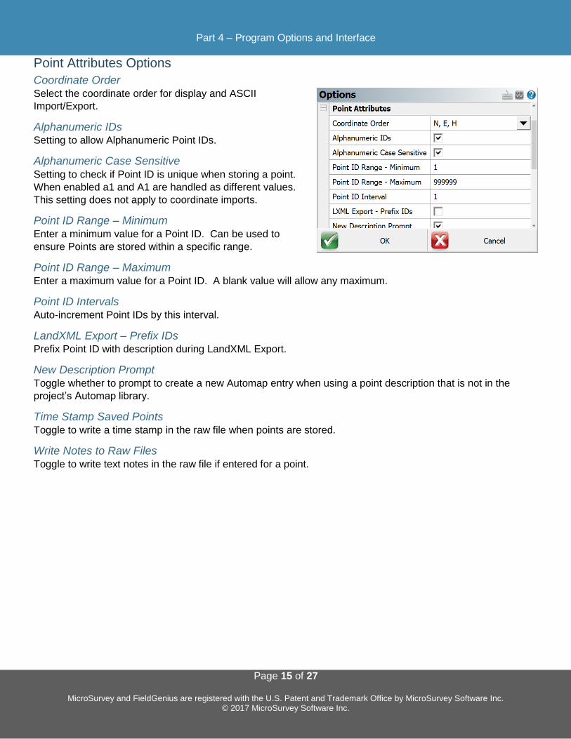
Point Attributes Options
Coordinate Order Select the coordinate order for display and ASCII
Import/Export.
Alphanumeric IDs Setting to allow Alphanumeric Point IDs.
Alphanumeric Case Sensitive
Setting to check if Point ID is unique when storing a point.
When enabled a1 and A1 are handled as different values.
This setting does not apply to coordinate imports.
Point ID Range – Minimum Enter a minimum value for a Point ID. Can be used to
ensure Points are stored within a specific range.
Point ID Range – Maximum Enter a maximum value for a Point ID. A blank value will allow any maximum.
Point ID Intervals Auto-increment Point IDs by this interval.
LandXML Export – Prefix IDs Prefix Point ID with description during LandXML Export.
New Description Prompt
Toggle whether to prompt to create a new Automap entry when using a point description that is not in the
project’s Automap library.
Time Stamp Saved Points
Toggle to write a time stamp in the raw file when points are stored.
Write Notes to Raw Files Toggle to write text notes in the raw file if entered for a point.

Part 4 – Program Options and Interface
Page 16 of 27
MicroSurvey and FieldGenius are registered with the U.S. Patent and Trademark Office by MicroSurvey Software Inc. © 2017 MicroSurvey Software Inc.
Map Configurations Options
Show ID / Description / Elevation Select the Point attributes to display on the map screen.
Level of Detail Toggle smart filter of Point information based on zoom level.
Text Size (Map View) Text size of Point information on the map screen.
Map Position Select Toggle ability to tap on the screen to store a point or other
options from the Map Select Toolbar.
Map Point / Line / DXF Select
Select which types of objects can be selected on the map
screen.

Part 4 – Program Options and Interface
Page 17 of 27
MicroSurvey and FieldGenius are registered with the U.S. Patent and Trademark Office by MicroSurvey Software Inc. © 2017 MicroSurvey Software Inc.
GNSS Options
EP+ Records Toggle the format of the EP record written to the raw file.
The standard EP record contains a combined horizontal
RMS value, while the EP+ record contains RMS values for
Northing and Easting. EP+ records are required when
seeding positions with regards to L-band correction
services.
Post Processing Tagging Start and End times of GNSS measurements can be written
to the raw file as comments. These values are required for
post processing raw data with Effigis OnPOZ (EZSurv)
software. NOTE: End times are captured when the user
picks the Store Position button on the GNSS Measurement
dialog.
Leap Seconds (GPS-UTC) Some receivers report UTC time instead of GPS time. When writing Start and End times for GNSS
measurements, the Leap Seconds value will be applied to the UTC time to ensure GPS time is recorded.
NOTE: This value will change over time and is the responsibility of the user to ensure it is current. This value
only applies to those receivers that report UTC time.
Prompt Raw Logging
Raw data logging on most receivers must be manually initialized. A prompt can be displayed at connection
time to remind the user to start raw data logging on the receiver.
Test Incoming Data Stream
Some GNSS receivers automatically connect to the previous correction link. FieldGenius can test for incoming
corrections at connection time to eliminate the Link Configure step.
Display GNSS Reference Setup
When connecting to a reference receiver, a prompt can be displayed to remind the user of the steps to take to
complete a reference setup.
Part 4 – Program Options and Interface
Page 18 of 27
MicroSurvey and FieldGenius are registered with the U.S. Patent and Trademark Office by MicroSurvey Software Inc. © 2017 MicroSurvey Software Inc.
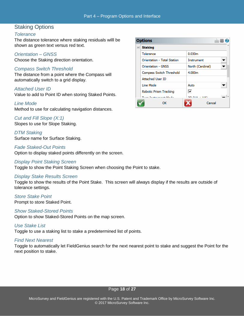
Staking Options
Tolerance The distance tolerance where staking residuals willl be
shown as green text versus red text.
Orientation – GNSS Choose the Staking direction orientation.
Compass Switch Threshold
The distance from a point where the Compass will
automatically switch to a grid display.
Attached User ID Value to add to Point ID when storing Staked Points.
Line Mode Method to use for calculating navigation distances.
Cut and Fill Slope (X:1) Slopes to use for Slope Staking.
DTM Staking Surface name for Surface Staking.
Fade Staked-Out Points Option to display staked points differently on the screen.
Display Point Staking Screen Toggle to show the Point Staking Screen when choosing the Point to stake.
Display Stake Results Screen Toggle to show the results of the Point Stake. This screen will always display if the results are outside of
tolerance settings.
Store Stake Point Prompt to store Staked Point.
Show Staked-Stored Points Option to show Staked-Stored Points on the map screen.
Use Stake List Toggle to use a staking list to stake a predetermined list of points.
Find Next Nearest
Toggle to automatically let FieldGenius search for the next nearest point to stake and suggest the Point for the
next position to stake.
Part 4 – Program Options and Interface
Page 19 of 27
MicroSurvey and FieldGenius are registered with the U.S. Patent and Trademark Office by MicroSurvey Software Inc. © 2017 MicroSurvey Software Inc.
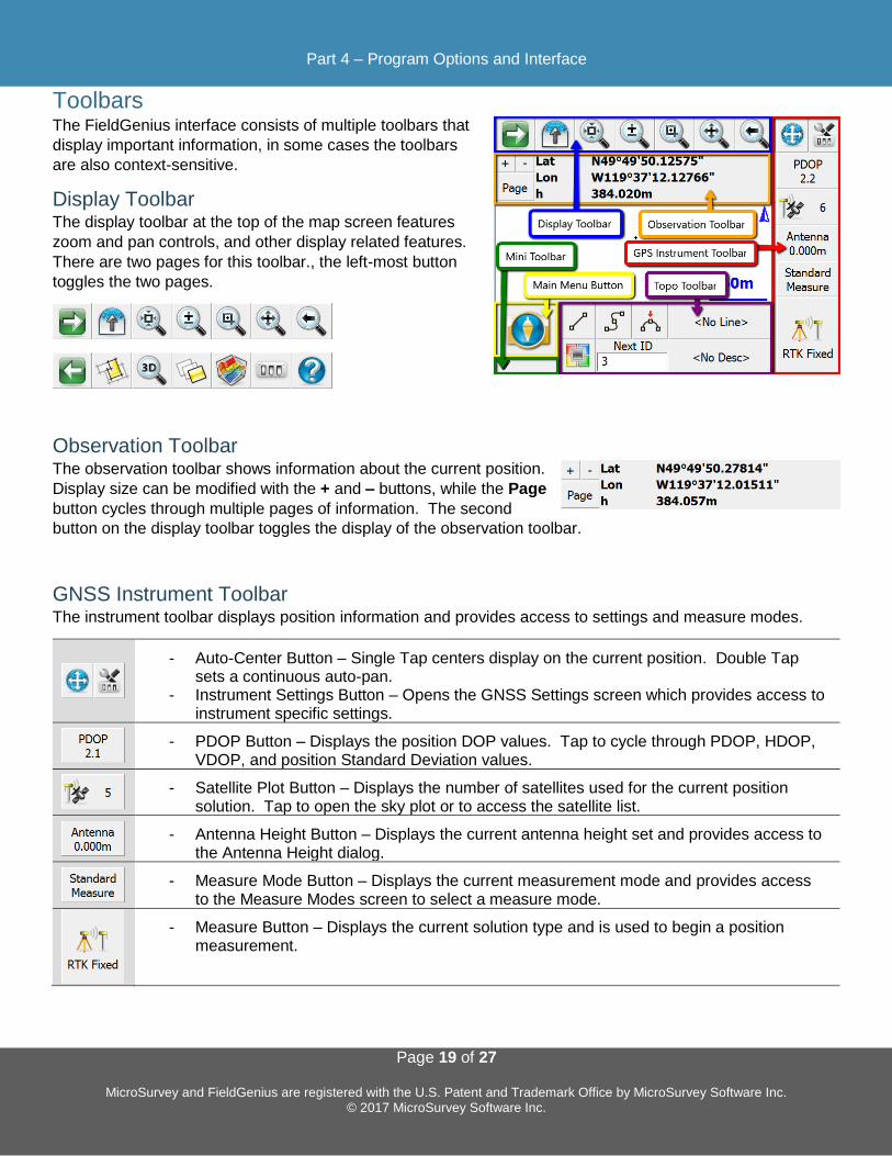
Toolbars The FieldGenius interface consists of multiple toolbars that
display important information, in some cases the toolbars
are also context-sensitive.
Display Toolbar The display toolbar at the top of the map screen features
zoom and pan controls, and other display related features.
There are two pages for this toolbar., the left-most button
toggles the two pages.
Observation Toolbar The observation toolbar shows information about the current position.
Display size can be modified with the + and – buttons, while the Page
button cycles through multiple pages of information. The second
button on the display toolbar toggles the display of the observation toolbar.
GNSS Instrument Toolbar The instrument toolbar displays position information and provides access to settings and measure modes.
- Auto-Center Button – Single Tap centers display on the current position. Double Tap sets a continuous auto-pan.
- Instrument Settings Button – Opens the GNSS Settings screen which provides access to instrument specific settings.
- PDOP Button – Displays the position DOP values. Tap to cycle through PDOP, HDOP,
VDOP, and position Standard Deviation values.
- Satellite Plot Button – Displays the number of satellites used for the current position
solution. Tap to open the sky plot or to access the satellite list.
- Antenna Height Button – Displays the current antenna height set and provides access to
the Antenna Height dialog.
- Measure Mode Button – Displays the current measurement mode and provides access
to the Measure Modes screen to select a measure mode.
- Measure Button – Displays the current solution type and is used to begin a position measurement.
Part 4 – Program Options and Interface
Page 20 of 27
MicroSurvey and FieldGenius are registered with the U.S. Patent and Trademark Office by MicroSurvey Software Inc. © 2017 MicroSurvey Software Inc.
Topo Toolbar The Topo Toolbar features figure toggles to draw linework, displays the active
figure name, the active description, the Next Point ID and features a user-
definable button which by default is mapped to the Point Coordinate
Database.
Mini Toolbar The Mini Toolbar can be used to maximize the map screen size by hiding any/all unwanted toolbars.
Map Select Toolbar The Map Select Toolbar is a context-sensitive toolbar that
can be used to Store a Point at a position picked on the
map, or measure a distance on the map between two
picked positions. The Map Configuration Options can be
accessed from the second page of the Display Toolbar to
turn ON/OFF the aiblity to select a posiition on the map.
Point Toolbar The Point Toolbar is displayed when a point is selected on
the map screen.
Shortcuts on the top row of this toolbar are: Points List,
Inverse Tool, Store New Point, Edit Point, Delete Point,
Offset Tool and Drawing Tool.
Shortcuts on the second row are: Zoom to Point, Stake Point, Previous Point ID, Next Point ID, and Close.
Line Toolbar The Line Toolbar is displayed when a line or arc figure is
selected on the map screen.
Shortcuts on the top row of this toolbar are: Set Figure
Current, End Figure, Reverse Direction, Partition Figure,
Delete Segment, Delete Figure, and Close Figure.
Shortcuts on the second row are: Open Figure List, Drawing Tool, Convert Line to Spline, Offset Tool, Stake
Figure, Figure Information, and Close.
Part 5 – Measure Modes and Workflows
Page 21 of 27
MicroSurvey and FieldGenius are registered with the U.S. Patent and Trademark Office by MicroSurvey Software Inc. © 2017 MicroSurvey Software Inc.
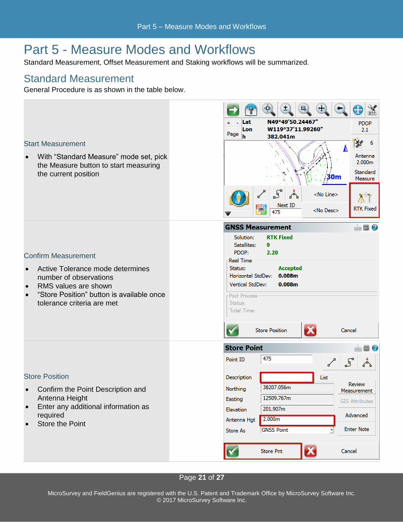
Part 5 - Measure Modes and Workflows Standard Measurement, Offset Measurement and Staking workflows will be summarized.
Standard Measurement General Procedure is as shown in the table below.
Start Measurement
• With “Standard Measure” mode set, pick
the Measure button to start measuring
the current position
Confirm Measurement
• Active Tolerance mode determines
number of observations
• RMS values are shown
• “Store Position” button is available once
tolerance criteria are met
Store Position
• Confirm the Point Description and
Antenna Height
• Enter any additional information as
required
• Store the Point

Part 5 – Measure Modes and Workflows
Page 22 of 27
MicroSurvey and FieldGenius are registered with the U.S. Patent and Trademark Office by MicroSurvey Software Inc. © 2017 MicroSurvey Software Inc.
Measurement Procedure Overview The measurement process works like this:
FieldGenius will only begin collecting measurement data if all your tolerances are met. During the
measurement process, you might see that certain tolerances are not being satisfied, which is normal.
FieldGenius will continue monitoring the measurement data and will accept measurements that pass the mask
criteria.
Once the tolerances have been met, the position status will change to an Accepted position. Prior to
accepting the position, the user can look at the RMS values for the computed position and determine if they
wish to accept or reject the measurement. Picking Cancel will exit the measure function without storing any
data. Picking Store Position will accept the position and store it in the database. The Antenna Height can be
changed on the Store Point screen.
Transformation parameters are applied to the GNSS position prior to storing the point.
If the current tolerance settings are not met, FieldGenius can switch from Real Time mode to Post Process
mode to collect static data for that point for later post processing back in the office. This switch from Real Time
mode to Post Process mode can occur automatically or manually, depending on the Post Process tolerance
settings. The duration of the Post Process measurement is specified in the tolerance settings, and depends on
the minimum number of satellites tracked during the entire Post Process session.
NOTE: The Action Settings of the active tolerance setting can be configured to skip over the GNSS
Measurement statistics screen and the Store Point screen.
Part 5 – Measure Modes and Workflows
Page 23 of 27
MicroSurvey and FieldGenius are registered with the U.S. Patent and Trademark Office by MicroSurvey Software Inc. © 2017 MicroSurvey Software Inc.
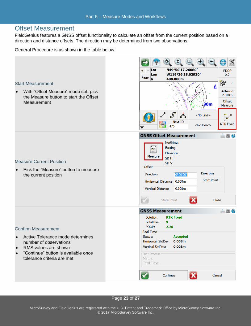
Offset Measurement FieldGenius features a GNSS offset functionality to calculate an offset from the current position based on a
direction and distance offsets. The direction may be determined from two observations.
General Procedure is as shown in the table below.
Start Measurement
• With “Offset Measure” mode set, pick
the Measure button to start the Offset
Measurement
Measure Current Position
• Pick the “Measure” button to measure
the current position
Confirm Measurement
• Active Tolerance mode determines
number of observations
• RMS values are shown
• “Continue” button is available once
tolerance criteria are met

Part 5 – Measure Modes and Workflows
Page 24 of 27
MicroSurvey and FieldGenius are registered with the U.S. Patent and Trademark Office by MicroSurvey Software Inc. © 2017 MicroSurvey Software Inc.
Enter Offset Values
• Enter Direction or use the “Start Point”
button to measure the first point of a
direction reference line. After
measuring the first reference point, the
button will change to “End Point” to
measure the second point.
• Enter Horizontal and Vertical Distance
Offsets
• Pick “Store Point”
Store Position
• Confirm the Point Description and
Antenna Height
• Enter any additional information as
required
• Store the Point

Part 5 – Measure Modes and Workflows
Page 25 of 27
MicroSurvey and FieldGenius are registered with the U.S. Patent and Trademark Office by MicroSurvey Software Inc. © 2017 MicroSurvey Software Inc.
Point Staking
Selecting a Point to Stake
Option 1
• Select the Point on the Map Screen
• Pick the Staking Button
Option 2
• Choose “Staking” from the
Measurement Modes menu
Option 2, Cont’d
• Choose “Stake Points”
NOTE: The Staking Menu is also available from the Main Menu.

Part 5 – Measure Modes and Workflows
Page 26 of 27
MicroSurvey and FieldGenius are registered with the U.S. Patent and Trademark Office by MicroSurvey Software Inc. © 2017 MicroSurvey Software Inc.
Point Staking Screen NOTE: This screen may not always be displayed,
depending on the Display Point Staking Screen setting.
On this screen:
1. The Point ID for the Point that will be staked.
2. Controls for selecting the next point to stake.
3. Offset values from the point coordinates. NOTE:
The Multi-Offset Mode will prevent the Point ID from
advancing when a point has been staked.
4. Stake the Point when ready.
Staking Interface The main Staking Interface provides a lot of
1. Pick this button to change the View Direction. The
default is stored as the Orientation – GNSS setting.
2. The Staking Toolbar provides access to:
a. Staking Method – Toggle between Grid,
Compass or Map View.
b. Staking Information – Displays the Point
Coordinates of the Point.
c. Observation Toolbar – Toggles the display of
the observation toolbar.
d. Next Point – Select the Next Point to stake,
from a variety of options.
e. Staking Options – Opens the Staking Options to configure any of the Staking options.
f. Close – Close the Staking Interface.
3. The Measure Button starts a measurement
Point Staking Results When a point has been measured, the Point Staking
Results screen is displayed if the Display Stake Results
Screen setting is enabled. If the tolerance settings are not
met, then the Staking Results are always displayed.
1. Save Point and Raw Data – Stores the staked point
in the coordinate database and writes the
measurement observation values to the raw file.
2. Save Raw Data – Only writes the measurement
observation values to the raw file.

Appendix
Page 27 of 27
MicroSurvey and FieldGenius are registered with the U.S. Patent and Trademark Office by MicroSurvey Software Inc. © 2017 MicroSurvey Software Inc.
Appendix Additional Resources for FieldGenius.
Online Manual A version of the complete FieldGenius manual is available online at:
http://s3.microsurvey.com/fieldgenius/Help/Default.htm
Movies A selection of instructional videos for FieldGenius are available online at:
http://helpdesk.microsurvey.com/index.php?/Knowledgebase/Article/View/149
Helpdesk Contact MicroSurvey Support through the MicroSurvey Helpdesk at:
http://helpdesk.microsurvey.com/
Geoid Models MicroSurvey provides a collection of geoid models for FieldGenius, files and instructions are available at:
http://helpdesk.microsurvey.com/index.php?/Knowledgebase/Article/View/479
Grid Shift Files MicroSurvey provides a collection of grid shift files for FieldGenius, files and instructions are available at:
http://helpdesk.microsurvey.com/index.php?/Knowledgebase/Article/View/499
Tutorials Base and Rover Setup
Line Staking
Area Calculations
Volume Calculations
Automap Libraries The Automap system is used in MicroSurvey field and office software:
http://helpdesk.microsurvey.com/index.php?/Knowledgebase/Article/View/1306
http://helpdesk.microsurvey.com/index.php?/Knowledgebase/Article/View/1350
Feature Files Feature List Editor Download http://s3.microsurvey.com/fieldgenius/Utilities/FeatureListEditor.exe
GIS Attributes Movies http://helpdesk.microsurvey.com/index.php?/Knowledgebase/Article/View/149#Attributes