glyn rhonwy pumped storage development consent order · glyn rhonwy pumped storage development...
TRANSCRIPT
Glyn Rhonwy Pumped Storage Development Consent Order
Deadline 3 – Excess Water Management Strategy
PINS Reference EN010072
Document Nos. SPH_GREX_DCOD3_04
Authors SPH/AECOM/GVA/BS
Revision Date Description
0 27th April 2016 Issued
Prepared by: Walter Robison .......................... Checked by: Dylan Huws Senior Engineer Associate Director
Approved by: Catherine AndersonAssociate Director
Glyn Rhonwy Pumped Storage – Excess Water Management Strategy
RevNo
Comments Checkedby
Approvedby
Date
0 Issued for DCO Deadline 3 DH CA Apr 2016
1 Tanfield, Edinburgh, EH3 5DATelephone: 0131 301 8600 Website: http://www.aecom.com
Job No 60484860 m001.004 April 2016
This document has been prepared by AECOM Limited for the sole use of our client (the “Client”) and inaccordance with generally accepted consultancy principles, the budget for fees and the terms of referenceagreed between AECOM Limited and the Client. Any information provided by third parties and referred toherein has not been checked or verified by AECOM Limited, unless otherwise expressly stated in thedocument. No third party may rely upon this document without the prior and express written agreement ofAECOM Limited.
Glyn Rhonwy PumpedStorage
Excess Water Management Strategy
TABLE OF CONTENTS
1 Introduction .................................................................................................................. 11.1 Introduction............................................................................................................. 11.2 the Development .................................................................................................... 11.3 Basic operation....................................................................................................... 21.4 Discharge locations ................................................................................................ 31.5 Abstraction location ................................................................................................ 4
2 Excess water management .......................................................................................... 52.1 Excess Water Management ................................................................................... 52.2 release of + excess water ....................................................................................... 52.3 abstraction for - excess water................................................................................. 62.4 Reservoir safety features and incidental release of water ...................................... 62.5 Environmental Management Systems .................................................................... 8
Appendix A: Drawings & Figures ..................................................................................... 10
Glyn Rhonwy PumpedStorage
Excess Water Management Strategy
Snowdonia Pumped Hydro Ltd. 1
1.1 INTRODUCTION
1.1.1 Optimum operation of the Development requires a constant volume of water within its closed
reservoir system. Rainfall on the reservoirs can cause additional or “excess water” within the system.
Whilst the reservoirs are designed to cope safely with the most severe rainfall that is expected to
occur, efficient operation of the Development is maintained by the management of excess water.
1.1.2 This Outline Excess Water Management Strategy is intended to set out the principles by which the
water within the Development is managed. This document sets out the strategy only; at the time of
writing the Development has not been subject to detailed design therefore a full operational algorithm
with precise values of each hydraulic element cannot be given. This strategy therefore cannot go into
detail on precise water levels, flows rates and volumes involved with specific movement of water
within the system.
1.1.3 For the background to the abstraction and discharge rates, together with the environmental and flood
risk appraisals, reference should be made to the Environmental Permitting applications to Natural
Resources Wales (NRW) and their supporting documentation.
1.2 THE DEVELOPMENT
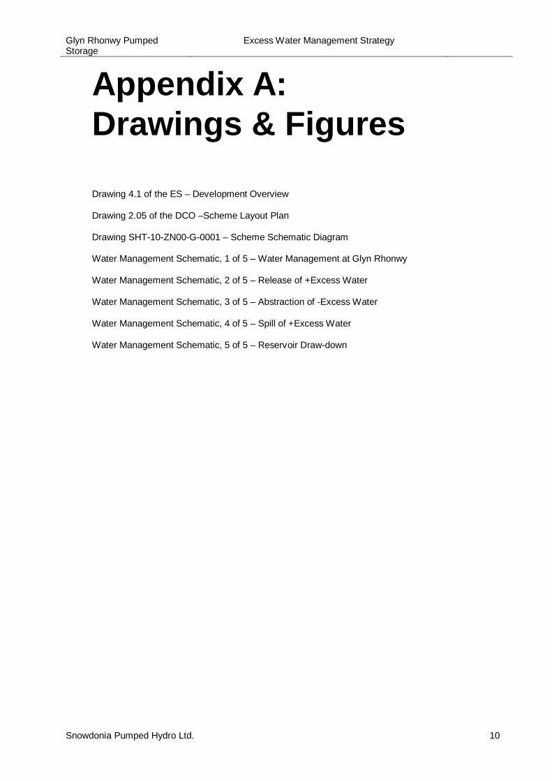
1.2.1 The Development at Glyn Rhonwy comprises a pumped storage hydro-electric scheme situated
within a series of disused slate quarries. The quarry system has been numbered from Q1 in the west
to Q8 in the east, which can be seen in Figure 2 in Appendix A. The quarries used in the
Development are:
· Quarry 1 (Q1) – Chwarel Fawr; Headpond
· Quarry 6 (Q6) – Glyn Rhonwy; Tailpond
1.2.2 The Development comprises of the following permanent features:
· Headpond reservoir (Q1), its dam, access shaft and spillway infrastructure to the Nant Y Betws;
· Tailpond reservoir (Q6), its dam, access shaft and spillway infrastructure to Llyn Padarn;
· Pumping station in close proximity to Llyn Padarn;
· Power house at Glyn Rhonwy Industrial Estate Platform 5 (south of Q6) with underground
turbine hall housing pump turbines;
· Penstock (connecting Q1 to the power house); and
· Tailrace (connecting the power house to Q6).
1INTRODUCTION
Glyn Rhonwy PumpedStorage
Excess Water Management Strategy
Snowdonia Pumped Hydro Ltd. 2
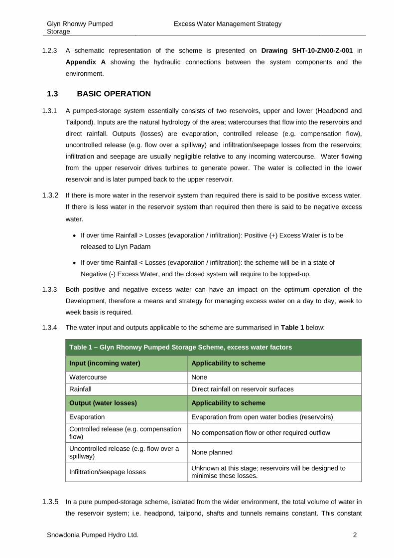
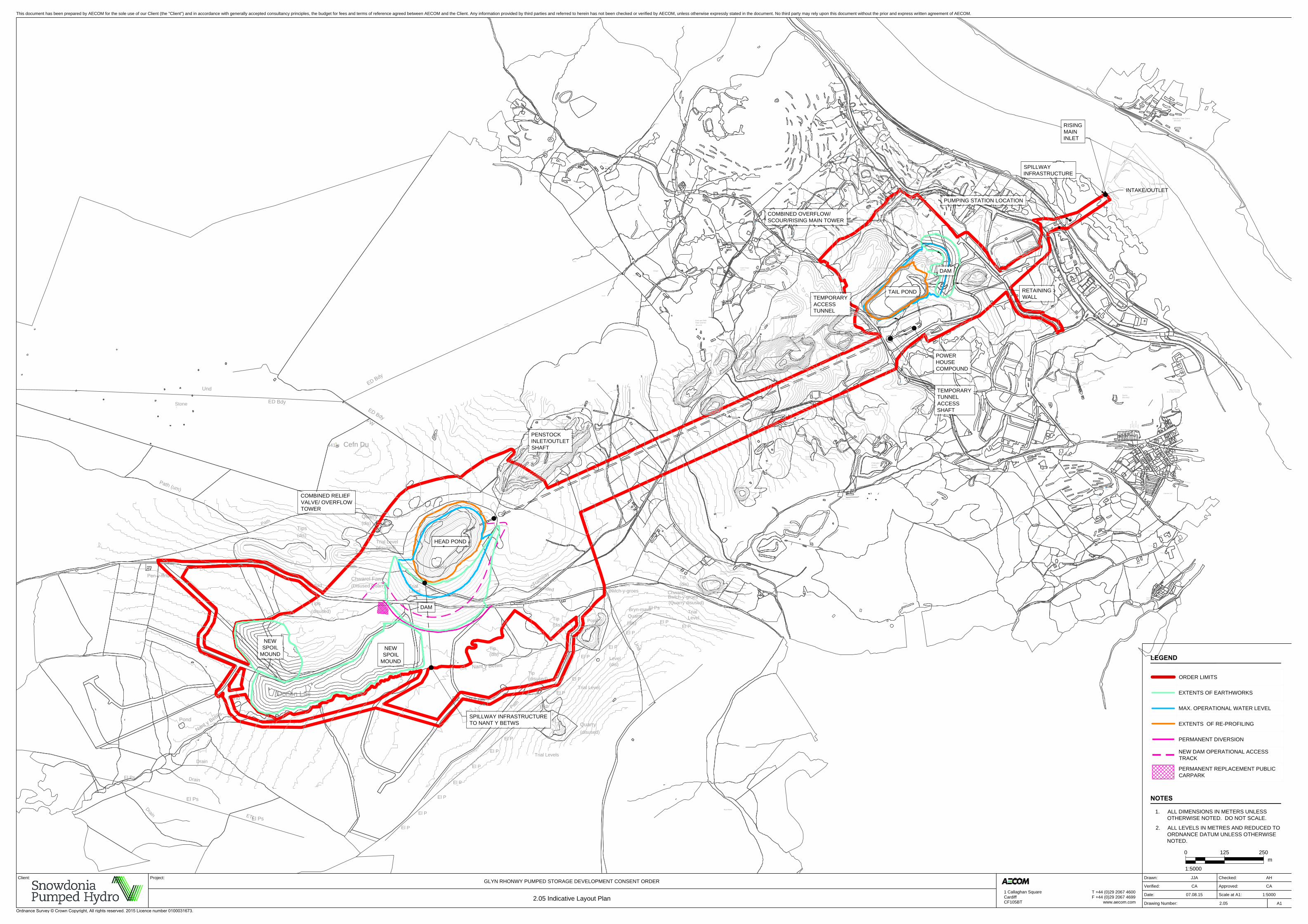
1.2.3 A schematic representation of the scheme is presented on Drawing SHT-10-ZN00-Z-001 in
Appendix A showing the hydraulic connections between the system components and the
environment.
1.3 BASIC OPERATION
1.3.1 A pumped-storage system essentially consists of two reservoirs, upper and lower (Headpond and
Tailpond). Inputs are the natural hydrology of the area; watercourses that flow into the reservoirs and
direct rainfall. Outputs (losses) are evaporation, controlled release (e.g. compensation flow),
uncontrolled release (e.g. flow over a spillway) and infiltration/seepage losses from the reservoirs;
infiltration and seepage are usually negligible relative to any incoming watercourse. Water flowing
from the upper reservoir drives turbines to generate power. The water is collected in the lower
reservoir and is later pumped back to the upper reservoir.
1.3.2 If there is more water in the reservoir system than required there is said to be positive excess water.
If there is less water in the reservoir system than required then there is said to be negative excess
water.
· If over time Rainfall > Losses (evaporation / infiltration): Positive (+) Excess Water is to be
released to Llyn Padarn
· If over time Rainfall < Losses (evaporation / infiltration): the scheme will be in a state of
Negative (-) Excess Water, and the closed system will require to be topped-up.
1.3.3 Both positive and negative excess water can have an impact on the optimum operation of the
Development, therefore a means and strategy for managing excess water on a day to day, week to
week basis is required.
1.3.4 The water input and outputs applicable to the scheme are summarised in Table 1 below:
Table 1 – Glyn Rhonwy Pumped Storage Scheme, excess water factors
Input (incoming water) Applicability to scheme
Watercourse None
Rainfall Direct rainfall on reservoir surfaces
Output (water losses) Applicability to scheme
Evaporation Evaporation from open water bodies (reservoirs)
Controlled release (e.g. compensationflow) No compensation flow or other required outflow
Uncontrolled release (e.g. flow over aspillway) None planned
Infiltration/seepage losses Unknown at this stage; reservoirs will be designed tominimise these losses.
1.3.5 In a pure pumped-storage scheme, isolated from the wider environment, the total volume of water in
the reservoir system; i.e. headpond, tailpond, shafts and tunnels remains constant. This constant
Glyn Rhonwy PumpedStorage
Excess Water Management Strategy
Snowdonia Pumped Hydro Ltd. 3
volume of water is simply moved between the upper and lower reservoirs during the
generating/pumping cycle.
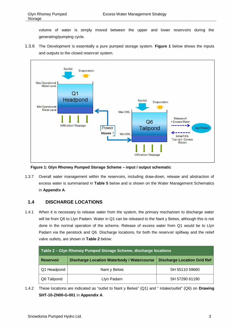
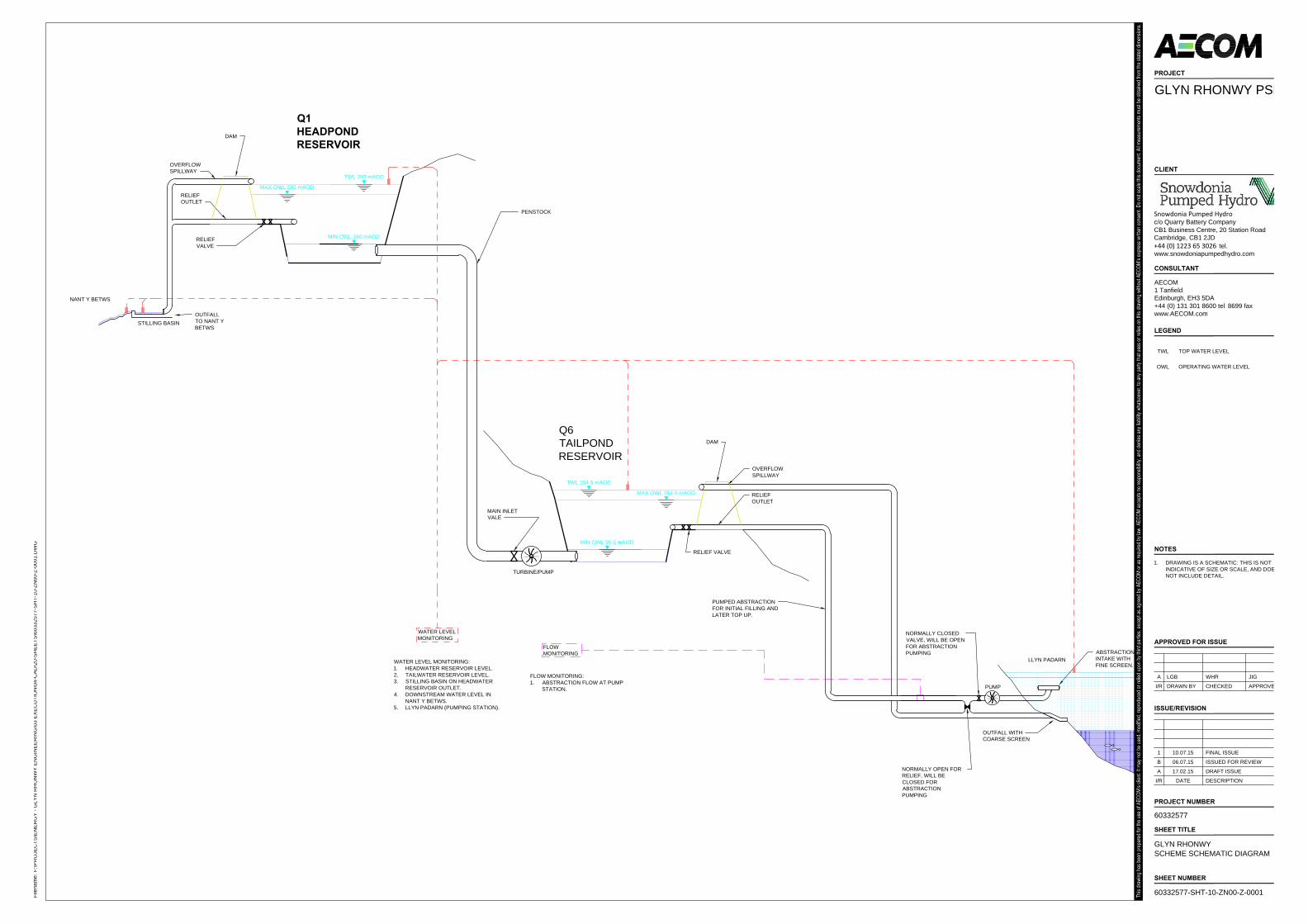
1.3.6 The Development is essentially a pure pumped storage system. Figure 1 below shows the inputs
and outputs to the closed reservoir system.
Figure 1: Glyn Rhonwy Pumped Storage Scheme – input / output schematic
1.3.7 Overall water management within the reservoirs, including draw-down, release and abstraction of
excess water is summarised in Table 5 below and is shown on the Water Management Schematics
in Appendix A.
1.4 DISCHARGE LOCATIONS
1.4.1 When it is necessary to release water from the system, the primary mechanism to discharge water
will be from Q6 to Llyn Padarn. Water in Q1 can be released to the Nant y Betws, although this is not
done in the normal operation of the scheme. Release of excess water from Q1 would be to Llyn
Padarn via the penstock and Q6. Discharge locations, for both the reservoir spillway and the relief
valve outlets, are shown in Table 2 below:
Table 2 – Glyn Rhonwy Pumped Storage Scheme, discharge locations
Reservoir Discharge Location Waterbody / Watercourse Discharge Location Grid Ref
Q1 Headpond Nant y Betws SH 55110 59660
Q6 Tailpond Llyn Padarn SH 57290 61190
1.4.2 These locations are indicated as “outlet to Nant y Betws” (Q1) and “ intake/outlet” (Q6) on DrawingSHT-10-ZN00-G-001 in Appendix A.
House
Glyn Rhonwy PumpedStorage
Excess Water Management Strategy
Snowdonia Pumped Hydro Ltd. 4
1.5 ABSTRACTION LOCATION
1.5.1 If it is necessary to abstract water to top up the closed reservoir system; water would be abstracted
from Llyn Padarn to the Tailpond (Q6). The abstraction location is the same as for the discharge
outlet to Llyn Padarn:
Table 3 – Glyn Rhonwy Pumped Storage Scheme, abstraction location
Reservoir Discharge Location Waterbody / Watercourse Discharge Location Grid Ref
Q6 Tailpond Llyn Padarn SH 57290 61190
Glyn Rhonwy PumpedStorage
Excess Water Management Strategy
Snowdonia Pumped Hydro Ltd. 5
2.1 EXCESS WATER MANAGEMENT
2.1.1 The hierarchy and logic diagram for operational discharges contained within Appendix A.
2.1.2 Positive “+” excess water is expected if over time rainfall exceeds evaporation and
infiltration/seepage from the reservoirs. During normal operation “+ Excess Water” is to be
released to Llyn Padarn from the tailpond Q6.
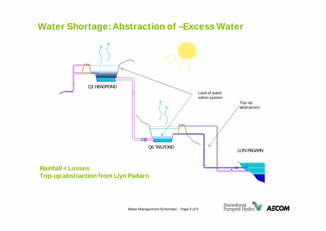
2.1.3 Negative “-” excess water may occur if over time losses from the system (evaporation,
infiltration/seepage) exceed the incoming rainfall falling on the surface of the reservoirs. In this
circumstance, the Development will require abstraction of water from Llyn Padarn to top up to
the required volume.
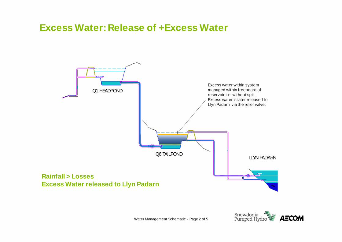
2.2 RELEASE OF + EXCESS WATER
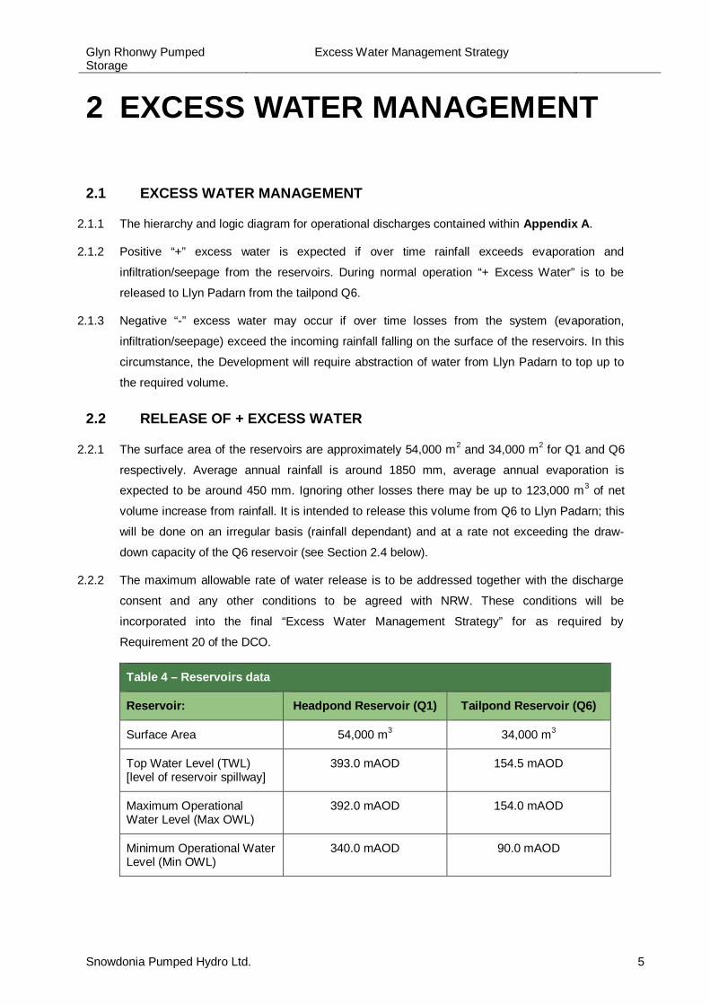
2.2.1 The surface area of the reservoirs are approximately 54,000 m2 and 34,000 m2 for Q1 and Q6
respectively. Average annual rainfall is around 1850 mm, average annual evaporation is
expected to be around 450 mm. Ignoring other losses there may be up to 123,000 m3 of net
volume increase from rainfall. It is intended to release this volume from Q6 to Llyn Padarn; this
will be done on an irregular basis (rainfall dependant) and at a rate not exceeding the draw-
down capacity of the Q6 reservoir (see Section 2.4 below).
2.2.2 The maximum allowable rate of water release is to be addressed together with the discharge
consent and any other conditions to be agreed with NRW. These conditions will be
incorporated into the final “Excess Water Management Strategy” for as required by
Requirement 20 of the DCO.
Table 4 – Reservoirs data
Reservoir: Headpond Reservoir (Q1) Tailpond Reservoir (Q6)
Surface Area 54,000 m3 34,000 m3
Top Water Level (TWL)[level of reservoir spillway]
393.0 mAOD 154.5 mAOD
Maximum OperationalWater Level (Max OWL)
392.0 mAOD 154.0 mAOD
Minimum Operational WaterLevel (Min OWL)
340.0 mAOD 90.0 mAOD
2 EXCESS WATER MANAGEMENT
Glyn Rhonwy PumpedStorage
Excess Water Management Strategy
Snowdonia Pumped Hydro Ltd. 6
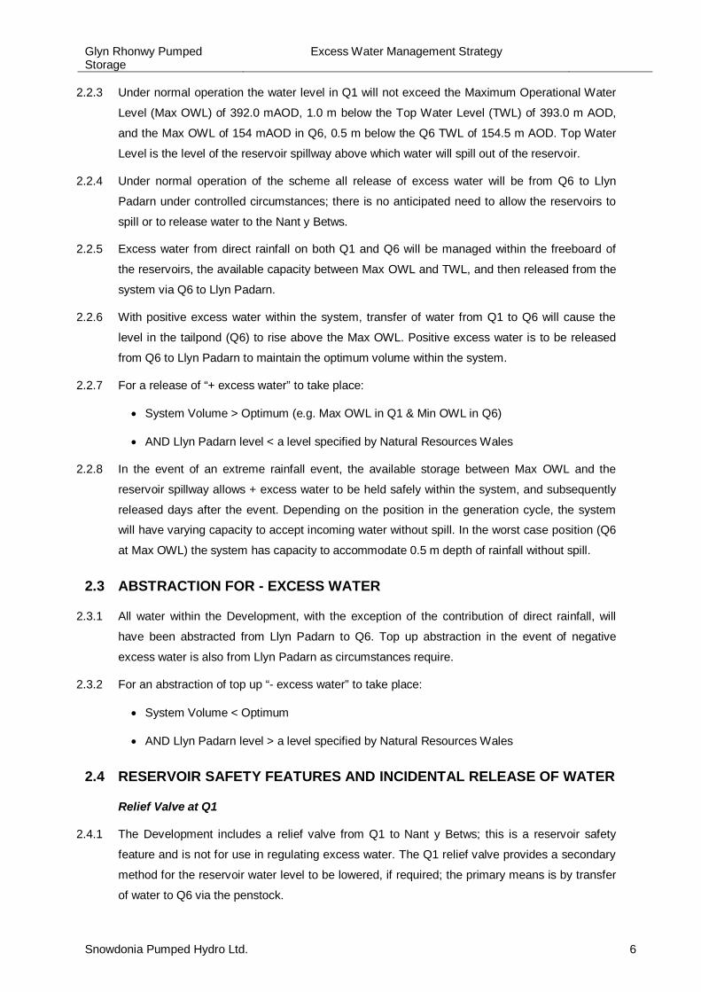
2.2.3 Under normal operation the water level in Q1 will not exceed the Maximum Operational Water
Level (Max OWL) of 392.0 mAOD, 1.0 m below the Top Water Level (TWL) of 393.0 m AOD,
and the Max OWL of 154 mAOD in Q6, 0.5 m below the Q6 TWL of 154.5 m AOD. Top Water
Level is the level of the reservoir spillway above which water will spill out of the reservoir.
2.2.4 Under normal operation of the scheme all release of excess water will be from Q6 to Llyn
Padarn under controlled circumstances; there is no anticipated need to allow the reservoirs to
spill or to release water to the Nant y Betws.
2.2.5 Excess water from direct rainfall on both Q1 and Q6 will be managed within the freeboard of
the reservoirs, the available capacity between Max OWL and TWL, and then released from the
system via Q6 to Llyn Padarn.
2.2.6 With positive excess water within the system, transfer of water from Q1 to Q6 will cause the
level in the tailpond (Q6) to rise above the Max OWL. Positive excess water is to be released
from Q6 to Llyn Padarn to maintain the optimum volume within the system.
2.2.7 For a release of “+ excess water” to take place:
· System Volume > Optimum (e.g. Max OWL in Q1 & Min OWL in Q6)
· AND Llyn Padarn level < a level specified by Natural Resources Wales
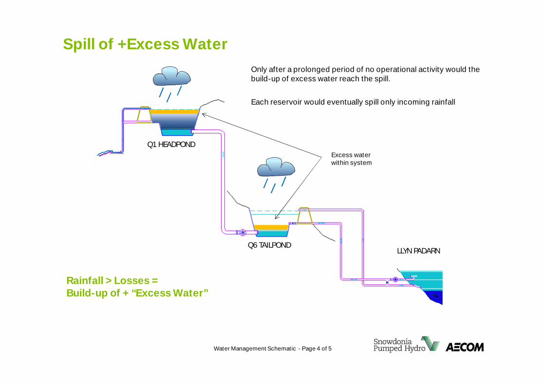
2.2.8 In the event of an extreme rainfall event, the available storage between Max OWL and the
reservoir spillway allows + excess water to be held safely within the system, and subsequently
released days after the event. Depending on the position in the generation cycle, the system
will have varying capacity to accept incoming water without spill. In the worst case position (Q6
at Max OWL) the system has capacity to accommodate 0.5 m depth of rainfall without spill.
2.3 ABSTRACTION FOR - EXCESS WATER
2.3.1 All water within the Development, with the exception of the contribution of direct rainfall, will
have been abstracted from Llyn Padarn to Q6. Top up abstraction in the event of negative
excess water is also from Llyn Padarn as circumstances require.
2.3.2 For an abstraction of top up “- excess water” to take place:
· System Volume < Optimum
· AND Llyn Padarn level > a level specified by Natural Resources Wales
2.4 RESERVOIR SAFETY FEATURES AND INCIDENTAL RELEASE OF WATER
Relief Valve at Q1
2.4.1 The Development includes a relief valve from Q1 to Nant y Betws; this is a reservoir safety
feature and is not for use in regulating excess water. The Q1 relief valve provides a secondary
method for the reservoir water level to be lowered, if required; the primary means is by transfer
of water to Q6 via the penstock.
Glyn Rhonwy PumpedStorage
Excess Water Management Strategy
Snowdonia Pumped Hydro Ltd. 7
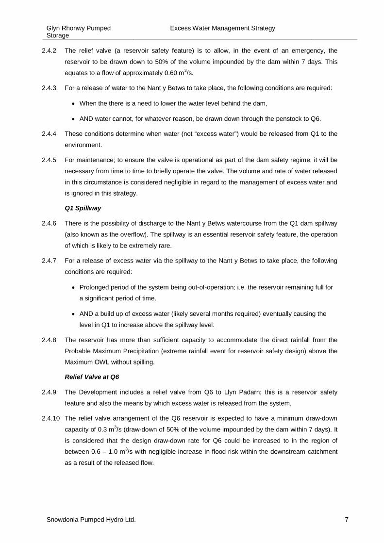
2.4.2 The relief valve (a reservoir safety feature) is to allow, in the event of an emergency, the
reservoir to be drawn down to 50% of the volume impounded by the dam within 7 days. This
equates to a flow of approximately 0.60 m3/s.
2.4.3 For a release of water to the Nant y Betws to take place, the following conditions are required:
· When the there is a need to lower the water level behind the dam,
· AND water cannot, for whatever reason, be drawn down through the penstock to Q6.
2.4.4 These conditions determine when water (not “excess water”) would be released from Q1 to the
environment.
2.4.5 For maintenance; to ensure the valve is operational as part of the dam safety regime, it will be
necessary from time to time to briefly operate the valve. The volume and rate of water released
in this circumstance is considered negligible in regard to the management of excess water and
is ignored in this strategy.
Q1 Spillway
2.4.6 There is the possibility of discharge to the Nant y Betws watercourse from the Q1 dam spillway
(also known as the overflow). The spillway is an essential reservoir safety feature, the operation
of which is likely to be extremely rare.
2.4.7 For a release of excess water via the spillway to the Nant y Betws to take place, the following
conditions are required:
· Prolonged period of the system being out-of-operation; i.e. the reservoir remaining full for
a significant period of time.
· AND a build up of excess water (likely several months required) eventually causing the
level in Q1 to increase above the spillway level.
2.4.8 The reservoir has more than sufficient capacity to accommodate the direct rainfall from the
Probable Maximum Precipitation (extreme rainfall event for reservoir safety design) above the
Maximum OWL without spilling.
Relief Valve at Q6
2.4.9 The Development includes a relief valve from Q6 to Llyn Padarn; this is a reservoir safety
feature and also the means by which excess water is released from the system.
2.4.10 The relief valve arrangement of the Q6 reservoir is expected to have a minimum draw-down
capacity of 0.3 m3/s (draw-down of 50% of the volume impounded by the dam within 7 days). It
is considered that the design draw-down rate for Q6 could be increased to in the region of
between 0.6 – 1.0 m3/s with negligible increase in flood risk within the downstream catchment
as a result of the released flow.
Glyn Rhonwy PumpedStorage
Excess Water Management Strategy
Snowdonia Pumped Hydro Ltd. 8
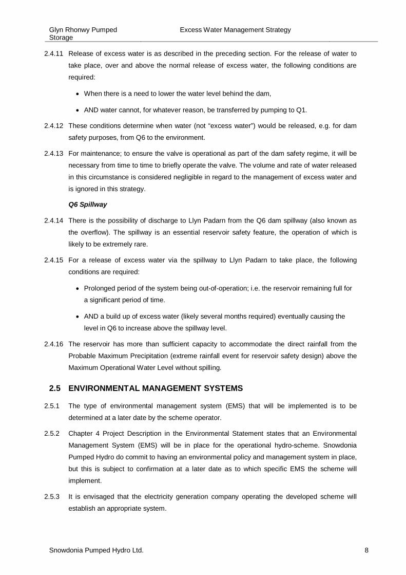
2.4.11 Release of excess water is as described in the preceding section. For the release of water to
take place, over and above the normal release of excess water, the following conditions are
required:
· When there is a need to lower the water level behind the dam,
· AND water cannot, for whatever reason, be transferred by pumping to Q1.
2.4.12 These conditions determine when water (not “excess water”) would be released, e.g. for dam
safety purposes, from Q6 to the environment.
2.4.13 For maintenance; to ensure the valve is operational as part of the dam safety regime, it will be
necessary from time to time to briefly operate the valve. The volume and rate of water released
in this circumstance is considered negligible in regard to the management of excess water and
is ignored in this strategy.
Q6 Spillway
2.4.14 There is the possibility of discharge to Llyn Padarn from the Q6 dam spillway (also known as
the overflow). The spillway is an essential reservoir safety feature, the operation of which is
likely to be extremely rare.
2.4.15 For a release of excess water via the spillway to Llyn Padarn to take place, the following
conditions are required:
· Prolonged period of the system being out-of-operation; i.e. the reservoir remaining full for
a significant period of time.
· AND a build up of excess water (likely several months required) eventually causing the
level in Q6 to increase above the spillway level.
2.4.16 The reservoir has more than sufficient capacity to accommodate the direct rainfall from the
Probable Maximum Precipitation (extreme rainfall event for reservoir safety design) above the
Maximum Operational Water Level without spilling.
2.5 ENVIRONMENTAL MANAGEMENT SYSTEMS
2.5.1 The type of environmental management system (EMS) that will be implemented is to be
determined at a later date by the scheme operator.
2.5.2 Chapter 4 Project Description in the Environmental Statement states that an Environmental
Management System (EMS) will be in place for the operational hydro-scheme. Snowdonia
Pumped Hydro do commit to having an environmental policy and management system in place,
but this is subject to confirmation at a later date as to which specific EMS the scheme will
implement.
2.5.3 It is envisaged that the electricity generation company operating the developed scheme will
establish an appropriate system.
Glyn Rhonwy PumpedStorage
Excess Water Management Strategy
Snowdonia Pumped Hydro Ltd. 9
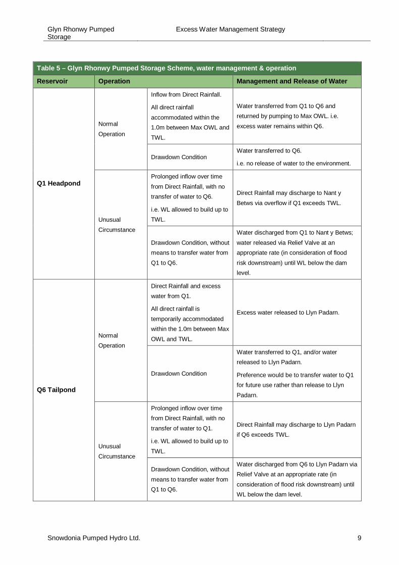
Table 5 – Glyn Rhonwy Pumped Storage Scheme, water management & operation
Reservoir Operation Management and Release of Water
Q1 Headpond
NormalOperation
Inflow from Direct Rainfall.
All direct rainfallaccommodated within the1.0m between Max OWL andTWL.
Water transferred from Q1 to Q6 andreturned by pumping to Max OWL. i.e.excess water remains within Q6.
Drawdown ConditionWater transferred to Q6.
i.e. no release of water to the environment.
UnusualCircumstance
Prolonged inflow over timefrom Direct Rainfall, with notransfer of water to Q6.
i.e. WL allowed to build up toTWL.
Direct Rainfall may discharge to Nant yBetws via overflow if Q1 exceeds TWL.
Drawdown Condition, withoutmeans to transfer water fromQ1 to Q6.
Water discharged from Q1 to Nant y Betws;water released via Relief Valve at anappropriate rate (in consideration of floodrisk downstream) until WL below the damlevel.
Q6 Tailpond
NormalOperation
Direct Rainfall and excesswater from Q1.
All direct rainfall istemporarily accommodatedwithin the 1.0m between MaxOWL and TWL.
Excess water released to Llyn Padarn.
Drawdown Condition
Water transferred to Q1, and/or waterreleased to Llyn Padarn.
Preference would be to transfer water to Q1for future use rather than release to LlynPadarn.
UnusualCircumstance
Prolonged inflow over timefrom Direct Rainfall, with notransfer of water to Q1.
i.e. WL allowed to build up toTWL.
Direct Rainfall may discharge to Llyn Padarnif Q6 exceeds TWL.
Drawdown Condition, withoutmeans to transfer water fromQ1 to Q6.
Water discharged from Q6 to Llyn Padarn viaRelief Valve at an appropriate rate (inconsideration of flood risk downstream) untilWL below the dam level.
Glyn Rhonwy PumpedStorage
Excess Water Management Strategy
Snowdonia Pumped Hydro Ltd. 10
Drawing 4.1 of the ES – Development Overview
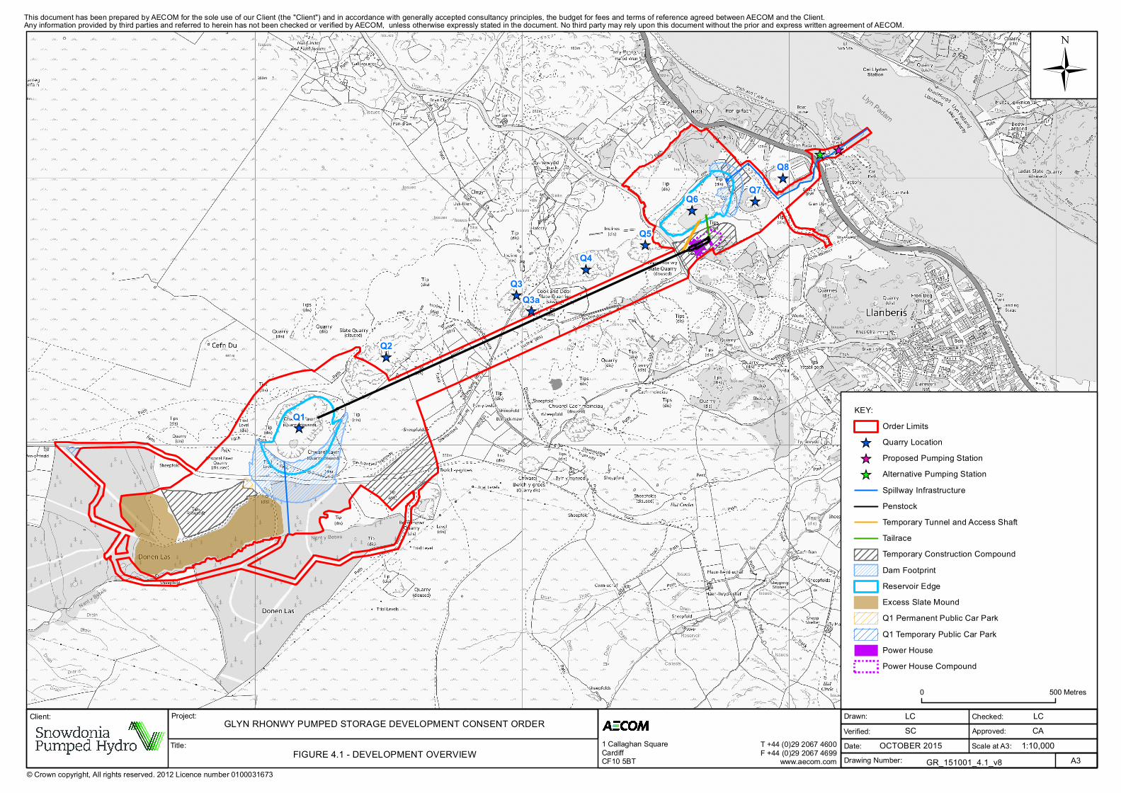
Drawing 2.05 of the DCO –Scheme Layout Plan
Drawing SHT-10-ZN00-G-0001 – Scheme Schematic Diagram
Water Management Schematic, 1 of 5 – Water Management at Glyn Rhonwy
Water Management Schematic, 2 of 5 – Release of +Excess Water
Water Management Schematic, 3 of 5 – Abstraction of -Excess Water
Water Management Schematic, 4 of 5 – Spill of +Excess Water
Water Management Schematic, 5 of 5 – Reservoir Draw-down
Appendix A:Drawings & Figures
_̂_̂
_̂
_̂
_̂_̂
_̂
_̂
_̂_̂
_̂Q8
Q7Q6
Q5
Q4
Q3
Q2
Q1
Q3a
© Crown copyright, All rights reserved. 2012 Licence number 0100031673
This document has been prepared by AECOM for the sole use of our Client (the "Client") and in accordance with generally accepted consultancy principles, the budget for fees and terms of reference agreed between AECOM and the Client.
Verified:Date:
Checked:Approved:Scale at A3:
Drawing Number:
Any information provided by third parties and referred to herein has not been checked or verified by AECOM, unless otherwise expressly stated in the document. No third party may rely upon this document without the prior and express written agreement of AECOM.
Ü
0 500 Metres
Drawn:
A3
LCSC
LCCA
OCTOBER 2015GR_151001_4.1_v8
KEY:Order Limits
_̂ Quarry Location_̂ Proposed Pumping Station_̂ Alternative Pumping Station
Spillway InfrastructurePenstockTemporary Tunnel and Access ShaftTailraceTemporary Construction CompoundDam FootprintReservoir EdgeExcess Slate MoundQ1 Permanent Public Car ParkQ1 Temporary Public Car ParkPower HousePower House Compound
1:10,000Title:
Project:Client: GLYN RHONWY PUMPED STORAGE DEVELOPMENT CONSENT ORDER
FIGURE 4.1 - DEVELOPMENT OVERVIEW1 Callaghan SquareCardiffCF10 5BT
T +44 (0)29 2067 4600F +44 (0)29 2067 4699
www.aecom.com
Issues
Stones
Drain
1
8
Stepping
'Rallt Goch
Drain
Path
(um
)
FB
Issues
FB
Ty Newydd
Silos
Ty-newydd
Pond
Groeslon
T
ra
c
k
Tan-hafotty
Spring
Padarn
Pen-gilfach
127.7m
132.7m
Glyn Peris
128.9m
Cottage
Lodge
Glyn
Glyn Peris
Water
122.4m
130.1m
D
r
a
in
Sinks
C
l
i
f
f
MS
P
a
t
h
(
u
m
)
W
e
l
l
Tan-y-ffynnon
Issues
Hafod Wen
Well
Gwel Llyn
(Hotel)
Issues
Tip
LB
Tip
Lay-b
y
Pond
Pond
T
r
a
c
k
FB
Mast
L
a
y
-
b
y
Tip
(disused)
Pond
Sheepfold
I
n
c
l
i
n
e
(
d
i
s
u
s
e
d
)
T
r
a
c
k
FB
Barrack-mawr
P
a
t
h
(
u
m
)
Issues
(
d
i
s
u
s
e
d
)
Issues
Sheepfolds
(disused)
(d
is
u
s
e
d
)
Tip
P
a
t
h
(
u
m
)
T
r
a
c
k
In
c
lin
e
F
W
(d
is
u
s
e
d
)
In
c
lin
e
Llys Ellen
Clegyr
I
n
c
l
i
n
e
Pen-y-bwlch
Pond
Issues
Issues
Sinks
Foot Bridge
C
S
P
a
th
(
u
m
)
Issues
(disused)
P
a
t
h
(
u
m
)
P
a
t
h
(
u
m
)
Pond
Water
Slate Quarry
U
n
d
E
D
B
d
y
E
D
B
d
y
F
W
U
n
d
Tra
ck
D
is
m
a
n
tle
d
T
r
a
m
w
a
y
(disused)
Slate Quarries
Cook and Ddôl
D
i
s
m
a
n
t
l
e
d
T
r
a
m
w
a
y
D
i
s
m
a
n
t
l
e
d
T
r
a
m
w
a
y
T
u
n
n
e
l
(
d
is
)
Workings (dis)
Chwarel Cefn-dû
(disused)
Cefn Du
(dis)
P
a
th
Trial Level
Quarry
F
W
E
D
B
d
y
E
D
B
d
y
(dis)
Tips
441m
ED Bdy
P
a
t
h
P
a
t
h
(
u
m
)
Stone
Und
El P
Trial
Tip
Level
(dis)
El P
Bwlch-y-groes
(Quarry disused)
Chwarel
El P
(dis)
Level
Bwlch-y-groes
El Ps
El P
El P
El P
(disused)
(dis)
Trial Level
Pond
Quarry
Tip
El P
El P
El P
El P
El P
El P
El P
(dis)
Nant y
Betw
s
Trial Levels
Tip
Tip
P
a
t
h
(disused)
P
a
t
h
Pond
(dis)
Tip
El P
El P
Trial
Level
El P
U
n
d
Bryn-mawr
Quarry
(dis)
E
T
L
T
r
a
m
w
a
y
D
ism
antle
d
Donen Lâs
Sarn
C
S
E
D
B
dy
Sinks
C
W
Issues
P
a
t
h
(
u
m
)
Pond
T
r
a
c
k
Bryn Clyd
Issues
D
r
a
in
Pen-draw
Pond
Issues
Gallt-y-celyn
Issues
T
r
a
c
k
Pond
Pond
CG
(Disused Quarry)
Path
Chwarel Fawr
(disused)
Sheepfold
Sheepfold
Tips
E
T
L
El Ps
El Ps
D
rain
D
r
a
i
n
N
a
n
t
y
B
e
t
w
s
Drain
Pond
Pond
El Ps
Donen Lâs
Pen-y-ffrîdd
Issues
Sheepfold
Hafotty
Path
(um
)
Issues
(disused)
Cliff
Capel Clegyr
Sheepfold
Pond
P
a
t
h
(
u
m
)
Sinks
Issues
Issues
Quarry
Inclin
e (dis
used)
Sinks
(disused)
In
c
lin
e
(disused)
(
d
is
u
s
e
d
)
Chwarel Cae'r-meinciau
P
a
t
h
(
u
m
)
Issues
Issues
Sheepfold
Quarry
T
r
a
c
k
(disused)
Path (um)
(disused)
Quarry
Quarry
(disused)
Cae'r-ty
Reservoir
P
o
n
d
Tip
(disused)
Incline (
dis
used)
Cae'r-meinciau
Issues
P
a
th
(u
m
)
Pond
Issues
Ffridd-glyn Slate
Quarry
Issues
A
f
o
n
G
ly
n
(disused)
D
r
a
i
n
Heap (dis)
Pond
Heap (dis)
D
i
s
m
a
n
t
l
e
d
T
r
a
m
w
a
y
D
i
s
m
a
n
t
l
e
d
T
r
a
m
w
a
y
Glyn-rhonwy Slate Quarry
(disused)
T
r
a
c
k
Workings (dis)
T
r
a
c
k
Heap (dis)
Heap (dis)
P
a
th
(
u
m
)
Ford
Ty-dû
Plas Garnedd
Bronallt
Spring
D
r
a
i
n
C
a
r
l
i
n
i
g
K
M
P
Bryn
1
2
0
1
Ty-newydd
P
a
t
h
(
u
m
)
S
T
R
Y
D
I
A
N
C
I
2
Car Park
(
C
o
m
m
u
n
i
t
y
W
o
r
k
s
h
o
p
s
)
104.7m
1
G
w
a
i
t
h
d
a
i
C
y
m
u
n
e
d
o
l
7
(disused)
2
Sheepfold
4
D
r
a
in
TCP
Henryd
E
l
A
f
o
n
G
i
y
n
Glyn
1
9
FB
S
u
b
S
t
a
Cave
Path (um)
Ynys-wen
Coed Mawr
Rhonwy
9
Llwyn Dyrus
1
2
3
5
1
(Fron Deg Terrace)
3
1
2
9
7
G
L
Y
N
R
H
O
N
W
Y
2
2
1
9
2
3
Gw
ynant
9
Hyfryd
1
52
C
a
m
b
r
ia
n
Spring
1
0
8
Bod W
enallt
Y
S
T
A
D
1
Path
(um
)
3
C
ra
ig
w
e
l
Issues
D
D
I
W
Y
D
I
A
N
N
O
L
El
1
1
D
r
a
i
n
1
4
3
0
GVC
2
2
Rhes Fron Deg
Pond
2
5
T
a
n
k
1
5
S
T
R
Y
D
W
A
R
D
E
N
/
W
A
R
D
E
N
S
T
R
E
E
T
Sub Sta
2
0
1
0
R
h
e
s
1
Llainwen Isaf
LB
Fron Oleu
Llainw
en
Quarry
5
Derw
yn D
eg
Rhes
Wells
Rhes Olra/Olgra Terrace
Sheepfold
2
U
c
h
a
f
Llyn
Ponds
4
49
9
1
7
3
9
Eilian
Y
G
L
Y
N
Ael-y-Glyn
(
P
a
t
h
a
n
d
C
y
c
l
e
P
a
t
h
)
105.1m
7
1
Well
P
a
t
h
(
u
m
)
F
F
O
R
D
D
T
Y
D
U
/T
Y
D
U
R
O
A
D
1
6
5
Tan Dinas
Hafan
P
a
th
(u
m
)
P
a
t
h
(
u
m
)
Frondeg
Uchaf
Coed Doctor
Glan Llyn
Issues
(disused)
F
F
O
R
D
D
C
L
E
G
IR
Gallt-y-glyn
L
o
n
L
a
s
P
e
r
i
s
T
r
a
c
k
Works
Sluice
P
a
t
h
(
u
m
)
CG
Ford
Quarries
Shelter
Ford
Ystabl-gôch
Lake)
Tomos / Lewis
Ty'n-y-mynydd
(disused)
Chwarel Bwlch-y-groes
Path (um
)
Tips
(disused)
Bryn Mawr
D
r
a
in
Sheepfold
Dinas
E
T
L
D
is
m
a
n
tle
d
T
r
a
m
w
a
y
(
L
l
a
n
b
e
r
i
s
L
a
k
e
R
a
i
l
w
a
y
)
Llyn Padarn
Boundary Slate Quarry
(disused)
Sinks
P
a
t
h
(
u
m
)
E
D
B
d
y
C
L
a
k
e
T
r
a
c
k
Slate Quarry
A
4
0
8
6
Y Glyn
Path (um
)
Glyn-rhonwy
Cei Llydan
S
M
(
P
a
t
h
&
C
y
c
l
e
T
r
a
c
k
)
Factory
L
o
n
L
a
s
P
e
r
i
s
PC
A
4
0
8
6
Glyn Padarn
L
o
n
L
a
s
P
e
r
i
s
Fn
Boat House
FB
(disused)
(
P
a
t
h
&
C
y
c
l
e
T
r
a
c
k
)
P
a
t
h
(
u
m
)
C
a
r
P
a
r
k
INTAKE/OUTLET
TEMPORARY
TUNNEL
ACCESS
SHAFT
POWER
HOUSE
COMPOUND
PUMPING STATION LOCATION
SPILLWAY
INFRASTRUCTURE
PENSTOCK
INLET/OUTLET
SHAFT
RISING
MAIN
INLET
COMBINED OVERFLOW/
SCOUR/RISING MAIN TOWER
TEMPORARY
ACCESS
TUNNEL
RETAINING
WALL
NEW
SPOIL
MOUND
HEAD POND
TAIL POND
DAM
DAM
SPILLWAY INFRASTRUCTURE
TO NANT Y BETWS
COMBINED RELIEF
VALVE/ OVERFLOW
TOWER
HEAD POND
NEW
SPOIL
MOUND
1 Callaghan Square
Cardiff
CF105BT
T +44 (0)29 2067 4600
F +44 (0)29 2067 4699
www.aecom.com
Drawn:
Verified:
Date:
Drawing Number:
Checked:
Approved:
Scale at A1:
Project:Client:
This document has been prepared by AECOM for the sole use of our Client (the "Client") and in accordance with generally accepted consultancy principles, the budget for fees and terms of reference agreed between AECOM and the Client. Any information provided by third parties and referred to herein has not been checked or verified by AECOM, unless otherwise expressly stated in the document. No third party may rely upon this document without the prior and express written agreement of AECOM.
A1
GLYN RHONWY PUMPED STORAGE DEVELOPMENT CONSENT ORDER
2.05 Indicative Layout Plan
2.05
JJA AH
CA CA
07.08.15 1:5000
Ordnance Survey © Crown Copyright, All rights reserved. 2015 Licence number 0100031673.
ORDER LIMITS
EXTENTS OF EARTHWORKS
MAX. OPERATIONAL WATER LEVEL
EXTENTS OF RE-PROFILING
PERMANENT DIVERSION
NEW DAM OPERATIONAL ACCESS
TRACK
PERMANENT REPLACEMENT PUBLIC
CARPARK
1. ALL DIMENSIONS IN METERS UNLESS
OTHERWISE NOTED. DO NOT SCALE.
2. ALL LEVELS IN METRES AND REDUCED TO
ORDNANCE DATUM UNLESS OTHERWISE
NOTED.
LEGEND
NOTES
0 125 250
1:5000
m
MAX OWL 392 mAOD
Q1
HEADPOND
RESERVOIR
RELIEF
OUTLET
OVERFLOW
SPILLWAY
STILLING BASIN
TURBINE/PUMP
LLYN PADARN
PUMP
OVERFLOW
SPILLWAY
OUTFALL WITH
COARSE SCREEN
ABSTRACTION
INTAKE WITH
FINE SCREEN.
FLOW
MONITORING
WATER LEVEL
MONITORING
NANT Y BETWS
FLOW MONITORING:
1. ABSTRACTION FLOW AT PUMP
STATION.
WATER LEVEL MONITORING:
1. HEADWATER RESERVOIR LEVEL.
2. TAILWATER RESERVOIR LEVEL.
3. STILLING BASIN ON HEADWATER
RESERVOIR OUTLET.
4. DOWNSTREAM WATER LEVEL IN
NANT Y BETWS.
5. LLYN PADARN (PUMPING STATION).
OUTFALL
TO NANT Y
BETWS
PUMPED ABSTRACTION
FOR INITIAL FILLING AND
LATER TOP UP.
MIN OWL 340 mAOD
TWL 393 mAOD
MIN OWL 90.0 mAOD
TWL 154.5 mAOD
DAM
MAIN INLET
VALE
PENSTOCK
NORMALLY OPEN FOR
RELIEF, WILL BE
CLOSED FOR
ABSTRACTION
PUMPING
NORMALLY CLOSED
VALVE, WILL BE OPEN
FOR ABSTRACTION
PUMPING
Q6
TAILPOND
RESERVOIR
RELIEF
OUTLET
MAX OWL 154.0 mAOD
DAM
RELIEF VALVE
RELIEF
VALVE
TWL TOP WATER LEVEL
OWL OPERATING WATER LEVEL
I/R DATE DESCRIPTION
ISSUE/REVISION
A 17.02.15 DRAFT ISSUE
B 06.07.15 ISSUED FOR REVIEW
1 10.07.15 FINAL ISSUE
Filenam
e: F
:\P
RO
JE
CT
S\E
NE
RG
Y - G
LY
N R
HO
NW
Y E
NG
IN
EE
RIN
G\03 E
XE
CU
TIO
N\04-C
AD
\20-S
HE
ET
S\60332577-S
HT
-10-Z
N00-Z
-0001.D
WG
PROJECT
GLYN RHONWY PSH
PROJECT NUMBER
60332577
SHEET TITLE
GLYN RHONWY
SCHEME SCHEMATIC DIAGRAM
SHEET NUMBER
60332577-SHT-10-ZN00-Z-0001
CONSULTANT
AECOM
1 Tanfield
Edinburgh, EH3 5DA
+44 (0) 131 301 8600 tel 8699 fax
www.AECOM.com
LEGEND
NOTES
1. DRAWING IS A SCHEMATIC: THIS IS NOT
INDICATIVE OF SIZE OR SCALE, AND DOES
NOT INCLUDE DETAIL.
Snowdonia Pumped Hydroc/o Quarry Battery Company
CB1 Business Centre, 20 Station Road
Cambridge, CB1 2JD
+44 (0) 1223 65 3026 tel.
www.snowdoniapumpedhydro.com
I/R DRAWN BY CHECKED
APPROVED FOR ISSUE
APPROVED
A LGB WHR JIG
CLIENT
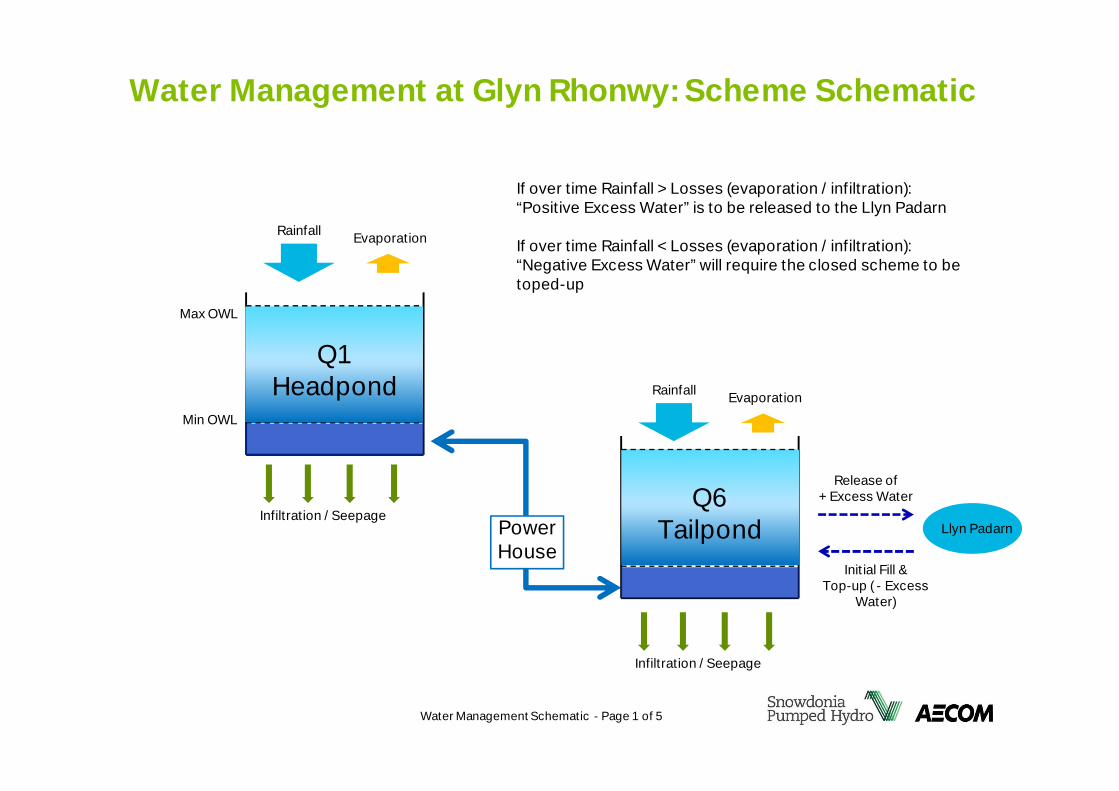
Water Management at Glyn Rhonwy: Scheme Schematic
Water Management Schematic - Page 1 of 5
Rainfall
Q1Headpond
PowerHouse
Infiltration / Seepage
Evaporation
Rainfall
Infiltration / Seepage
Evaporation
Max OWL
Min OWL
Q6Tailpond Llyn Padarn
Release of+ Excess Water
Initial Fill &Top-up ( - Excess
Water)
If over time Rainfall > Losses (evaporation / infiltration):“Positive Excess Water” is to be released to the Llyn Padarn
If over time Rainfall < Losses (evaporation / infiltration):“Negative Excess Water” will require the closed scheme to betoped-up
Q1 HEADPOND
Q6 TAILPONDLLYN PADARN
Excess Water: Release of +Excess Water
Rainfall > LossesExcess Water released to Llyn Padarn
Excess water within systemmanaged within freeboard ofreservoir; i.e. without spill.Excess water is later released toLlyn Padarn via the relief valve.
Water Management Schematic - Page 2 of 5
Q1 HEADPOND
Q6 TAILPONDLLYN PADARN
Water Shortage: Abstraction of –Excess Water
Rainfall < LossesTop-up abstraction from Llyn Padarn
Lack of waterwithin system
Top-upabstraction
Water Management Schematic - Page 3 of 5
Q1 HEADPOND
Q6 TAILPONDLLYN PADARN
Spill of +Excess Water
Rainfall > Losses =Build-up of + “Excess Water”
Excess waterwithin system
Only after a prolonged period of no operational activity would thebuild-up of excess water reach the spill.
Each reservoir would eventually spill only incoming rainfall
Water Management Schematic - Page 4 of 5
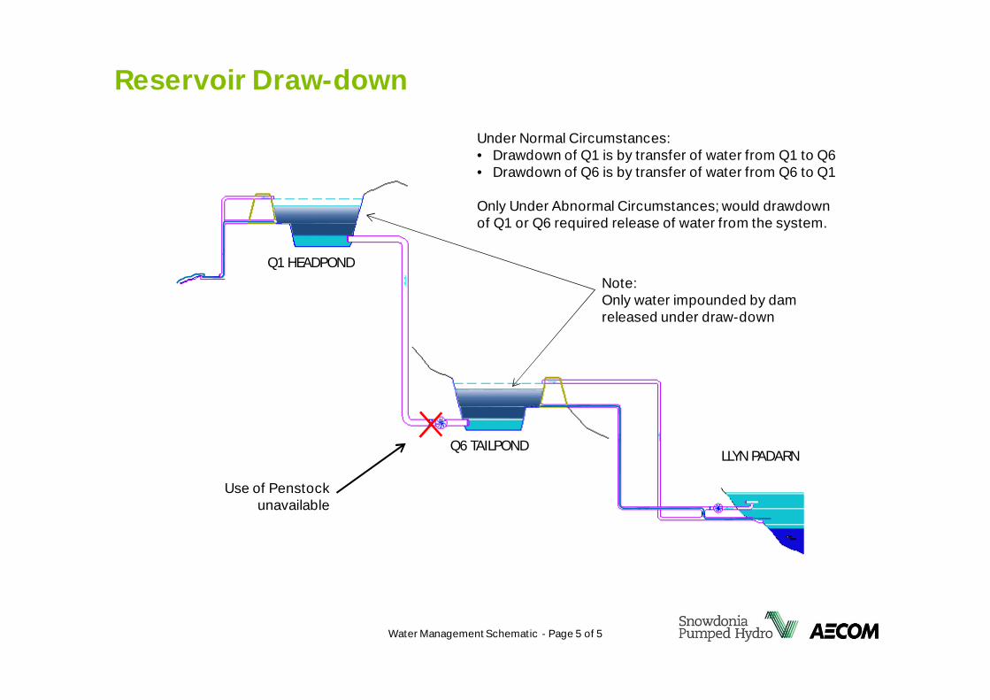
Reservoir Draw-down
Q1 HEADPOND
Q6 TAILPONDLLYN PADARN
Use of Penstockunavailable
Note:Only water impounded by damreleased under draw-down
Water Management Schematic - Page 5 of 5
Under Normal Circumstances:• Drawdown of Q1 is by transfer of water from Q1 to Q6• Drawdown of Q6 is by transfer of water from Q6 to Q1
Only Under Abnormal Circumstances; would drawdownof Q1 or Q6 required release of water from the system.