global vibration control of split stirling linear...
TRANSCRIPT
C19_064 1
Global Vibration Control of Split Stirling Linear Cryogenic Cooler
A. Veprik1, A. Tuito2
1 SemiConductor Devices, POB 2250, Haifa, 31021, Israel2 Israel Ministry of Defense, Kirya, Tel Aviv, 64734, Israel
ABSTRACTHigh operating temperature, low size, weight and power (SWAP) infrared imagers often rely on
miniature split Stirling linear cryocoolers composed of an electro-dynamically driven compressor and a pneumatically driven expander. For compactness, the two compoents are mounted side-by-
Vibration export produced by such a cryocooler may be thought of as a pair of tonal and coher-ent forces resulting from the almost sinusoidal imbalanced reciprocation of the moving assemblies inside the compressor and expander. The cooler-induced vibration of the infrared imager is, there-fore, comprised of a coupled angular and translational components manifesting themselves in the form of angular line of sight jitter and translational defocusing.
The authors present a Multimodal Tuned Dynamic Absorber, featuring translational and tilting
analysis shows that the dynamic reactions (force and moment) produced by such a dynamic absorber may simultaneously attenuate both translational and angular components of cryocooler-induced vibration, and improve the quality of the imagery.
INTRODUCTION
single-piston compressor offering lower SWAP and manufacturing expenses. This decision has been substantiated by the choice of a relatively high driving frequency (100 Hz
and above) leading to more compact design, smaller strokes and lower weight for the moving assem-blies, resulting in lower the vibration export magnitudes. Along with these lines, the visual effect of high-frequency interference is less harmful. This favorable combination makes SWAP single-piston
In the case of inherently more vibration sensitive lightweight hand-held and gyro-stabilized payloads, the magnitudes of the cooler-induced vibration may be reduced by a payload design. In
129Cryocoolers 19, edited by S.D. Miller and R.G. Ross, Jr.©¶International Cryocooler Conference, Inc., Boulder, CO, 2016
C19_064 2
gyro-stabilized applications, for example, the compressor and expander may be placed to minimize the moment about each gimbal axis.
When the design constraints prevent the prefered packaging or the payloads are sensitive to
using a Tuned Dynamic Absorber (TDA) mounted in-line with the compressor (major source of
the translational dynamic response at the attachment point. Usually, it is advised to make such a TDA in the form of an undamped “mass-spring” single degree of freedom (SDOF) translational system, where the frequencies of tilting, in-plane translations, rotation about the axis are well separated from the frequency of the axial translational mode, which needs to be tuned exactly to the driving frequency (or vice versa), see
Although the vibration export produced by the expander is relatively small, it cannot be disre-garded in the light-weight hand held and gyrostabilized electro-optic applications. In these cases, the in-line mounting of the compressor and the expander units is favorable. Single-axis consolidation of the exported vibration induced by the compressor and the expander allows for effective use of a single, inline mounted translational TDA. Unfortunately, this option is not always practical due to the packaging constraints. For compactness, the expander and compressor are usually packaged side-by-side. In this case, the expander-induced exported vibration may produce a moment about the payload center of gravity resulting in an angular line-of-sight jitter and a translational defocusing.
The authors present a patent pending tunable Multimodal Tuned Dynamic Absorber (MTDA) with the translational frequencies and the two tilting mode frequencies are essentially tuned to the driving frequency. Dynamic analysis shows that the dynamic reactions (force and moment) produced by such a dynamic absorber are capable of simultaneously attenuatiing the translational and angular components of cryocooler induced vibration.
DYNAMIC MODEL, EQUATIONS OF MOTION AND ANALYSIS
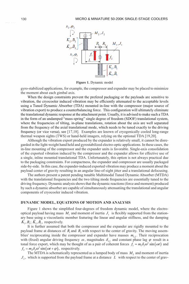
optical payload having mass 1M and moment of inertia 1J -ary base using a viscoelastic member featuring the linear and angular stiffness, and the damping
1 1 1 1, ; , ,B BK K respectively.It is further assumed that both the compressor and the expander are rigidly mounted to the
payload frame at distances of 1R and 2R with respect to the center of gravity. The moving assem-blies' reciprocating inside the compressor and expander have masses 1,2m . Their reciprocation
, magnitudes 1,2 and constant phase lag result in a tonal force export, which may be thought of as a pair of coherent forces 2
1 1 1 sinf m t and 2
2 2 2 sin ,f m t respectively. The MTDA is schematically represented as a lumped body of mass 2M and moment of inertia
2J , which is supported from the payload frame at a distance L with respect to the center of grav-
Figure 1. Dynamic model
MICRO & MINIATURE 50-200K SINGLE-STAGE COOLERS 130
C19_064 3ity using viscoelastic member featuring linear and angular stiffness and damping 2 2 2 2, ; ,B BK K , respectively. The translation and tilt responses are 1 1,x for the payload frame and 2 2,x for the MTDA, respectively.
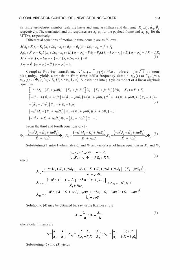
Differential equations of motion in time domain are as follows:
1 1 1 1 2 1 1 2 1 1 2 1 1 2 1 2
1 1 1 1 2 1 1 2 2 1 2 1 1 2 1 1 2 2 1 2 1 1 2 2
M x K x K x L x B x B x L x f f
J K K L x L x K B B L x L x B f R f R
2 2 2 1 1 2 2 1 1 2
2 2 2 1 2 2 1 2
0
0
M x K x L x B x L x
J K B
(1)
Complex Fourier transform, j tG j g t e dt , where 1j is com-
plex unity, yields a transition from time into a frequency domain 1,2 1,2 ,x t X j 1,2 1,2 1,2 1,2,t j f t F j . Substitution into (1) yields the set of 4 linear algebraic
equations: 2
1 1 1 2 2 1 2 2 1 2 1 2
2 21 1 1 2 2 2 2 1 2 2 1 2
2 2 2 1 1 2 2
22 2 2 2 2 2 1 1
22 2 2 2 2 2 1
0
0
M K j B K j B X K j B L X F F
J K j B K j B K j B L K j B L X X
K j B F R F R
M K j B X K j B X L
J K j B K j B
(2)
From the third and fourth equations of (2)
(3)
Substituting (3) into (1) eliminates 1 1andX and yields a set of linear equations in 2X and 2
(4)where
Solution to (4) may be obtained by, say, using Kramer’s rule
(5)
where determinants are
Substituting (5) into (3) yields
2 2 22 2 2 2 2 2 2 2 2
1 2 1 2 22 2 2 2 2 2
;J K j B M K j B J K j B
X X LK j B K j B K j B
GLOBAL VIBRATION CONTROL OF LINEAR STIRLING COOLER 131
C19_064 4 (6)
Assuming the case of ideally tuned, MTDA 2 22 2 2 2 2 2; ; 0; 0K M K J B B from
these are:2 1 2 2 2 1 1 2 2 1 2 2;X F F K F R F R L F F K (7)
From (7), the force of dynamic reaction exerted by MTDA upon the payload frame is 2 2 1 2K X F FQ , thus evidently counterbalancing aggregate force applied by the cryocooler.
Along with these lines, the moment of dynamic reaction exerted by MTDA upon the payload frame is 2 2 1 1 2 2 1 2K F R F R L F FT , thus evidently counterbalancing aggregate moment produced by the cryocooler along with the moment resulted from the MTDA translational motion.
Since 2 2andXto the driving frequency, we can use the below approximations
1 1 2 2 1 22 21 21 2 2 2 2 2 22 2
2 2
F R F R L F F LF FX M K j B J K j B
K K
1 0 and 1 0X at the driving frequency, provided 22 2K M , 2
2 2K J and 2 2 0B B -
calling that forces 1F and 2F are, generally speaking, complex numbers, we calculate the module of complex moment 1 1 2 2 1 2F R F R L F FT
(9)
which minimizes its magnitude, where notation means real part. It is worth noting that for
the split Stirling linear cryocooler, the magnitude ratio 2 1F F is almost constant over the wide range of working conditions typical of the temperature control operational mode. From (9), the op-timal position of MTDA will be, therefore, almost invariant over the range of working conditions.
For example, in the typical case 90deg and 2F , thus 2 2
1 1 2 22 2
2 1opt
F R F RL
F F; 2 2 2 22 1
min 1 1 2 2 1 22 22 1
F FF R R F R R
F FT (10)
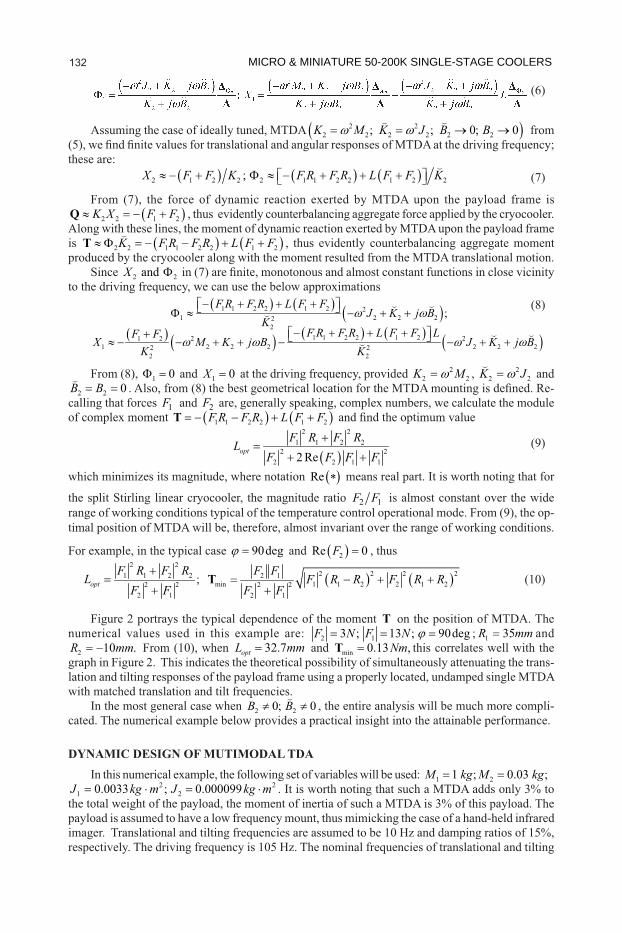
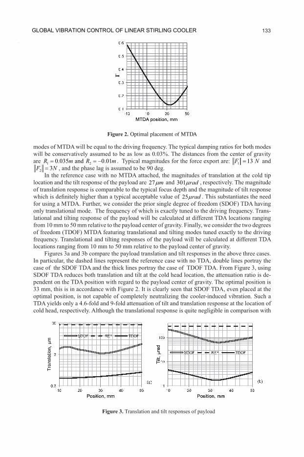
Figure 2 portrays the typical dependence of the moment T on the position of MTDA. The numerical values used in this example are: 2 13 ; 13 ; 90degF N F N ; 1 35R mm and
2 10 .R mm From (10), when 32.7optL mm and min 0.13 ,NmT this correlates well with the graph in Figure 2. This indicates the theoretical possibility of simultaneously attenuating the trans-lation and tilting responses of the payload frame using a properly located, undamped single MTDA with matched translation and tilt frequencies.
In the most general case when 2 20; 0B B , the entire analysis will be much more compli-cated. The numerical example below provides a practical insight into the attainable performance.
DYNAMIC DESIGN OF MUTIMODAL TDAIn this numerical example, the following set of variables will be used: 1 21 ; 0.03 ;M kg M kg
21 0.0033 ;J kg m 2
2 0.000099J kg m . It is worth noting that such a MTDA adds only 3% to the total weight of the payload, the moment of inertia of such a MTDA is 3% of this payload. The payload is assumed to have a low frequency mount, thus mimicking the case of a hand-held infrared imager. Translational and tilting frequencies are assumed to be 10 Hz and damping ratios of 15%, respectively. The driving frequency is 105 Hz. The nominal frequencies of translational and tilting
1 1 2 2 1 2 21 2 2 22
2
;F R F R L F F
J K j BK
2 21 1 2 2
2 22 2 1 1
optF R F R
LF F F F
MICRO & MINIATURE 50-200K SINGLE-STAGE COOLERS 132
C19_064 5
modes of MTDA will be equal to the driving frequency. The typical damping ratios for both modes will be conservatively assumed to be as low as 0.03%. The distances from the center of gravity are 1 20.035 and 0.01R m R m . Typical magnitudes for the force export are: 1 13F N and
2 3F N , and the phase lag is assumed to be 90 deg. In the reference case with no MTDA attached, the magnitudes of translation at the cold tip
location and the tilt response of the payload are 27 m and 301 rad , respectively. The magnitude of translation response is comparable to the typical focus depth and the magnitude of tilt response
25 rad . This substantiates the need for using a MTDA. Further, we consider the prior single degree of freedom (SDOF) TDA having only translational mode. The frequency of which is exactly tuned to the driving frequency. Trans-lational and tilting response of the payload will be calculated at different TDA locations ranging from 10 mm to 50 mm relative to the payload center of gravity. Finally, we consider the two degrees of freedom (TDOF) MTDA featuring translational and tilting modes tuned exactly to the driving frequency. Translational and tilting responses of the payload will be calculated at different TDA locations ranging from 10 mm to 50 mm relative to the payload center of gravity.
Figures 3a and 3b compare the payload translation and tilt responses in the above three cases. In particular, the dashed lines represent the reference case with no TDA, double lines portray the case of thr SDOF TDA and the thick lines portray the case of TDOF TDA. From Figure 3, using SDOF TDA reduces both translation and tilt at the cold head location, the attenuation ratio is de-pendent on the TDA position with regard to the payload center of gravity. The optimal position is 33 mm, this is in accordance with Figure 2. It is clearly seen that SDOF TDA, even placed at the optimal position, is not capable of completely neutralizing the cooler-induced vibration. Such a TDA yields only a 4.6-fold and 9-fold attenuation of tilt and translation response at the location of cold head, respectively. Although the translational response is quite negligible in comparison with
Figure 2. Optimal placement of MTDA
Figure 3. Translation and tilt responses of payload
GLOBAL VIBRATION CONTROL OF LINEAR STIRLING COOLER 133
C19_064 6the typical depth of focus, the achieved 65 rad magnitude of the payload tilt does not meet the requirement of 25 rad typical of a hand-held application.
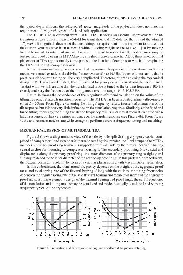
The TDOF TDA is different from SDOF TDA. It yields an essential improvement: the at-tenuation ratios are much higher: 45-fold for translation and 176-fold for the tilt and the attained 1.7 rad tilt magnitude does meet the most stringent requirements. It is important to notice, that these improvements have been achieved without adding weight to the MTDA – just by making favorable use of its rotational inertia. It is also important to notice that the performance may be further improved by using an MTDA having a higher moment of inertia. Along these lines, optimal placement of TDA approximately corresponds to the location of compressor which allows placing the TDA in-line with compressor axis.
In the previous reasoning, we assumed that the resonant frequencies of translational and tilting modes were tuned exactly to the driving frequency, namely to 105 Hz. It goes without saying that in practice such accurate tuning will be very complicated. Therefore, prior to advising the mechanical
To start with, we will assume that the translational mode is tuned to the driving frequency 105 Hz exactly and vary the frequency of the tilting mode over the range 104.5-105.5 Hz.
Figure 4a shows the dependences of the magnitude of tilt and translation on the value of the -
sor at 35L mm . From Figure 4a, tuning the tilting frequency results in essential attenuation of the
tuned tilting frequency, the tuning translation frequency results in essential attenuation of the trans-
4, the anti-resonant notches are wide enough to perform accurate frequency tuning and matching.
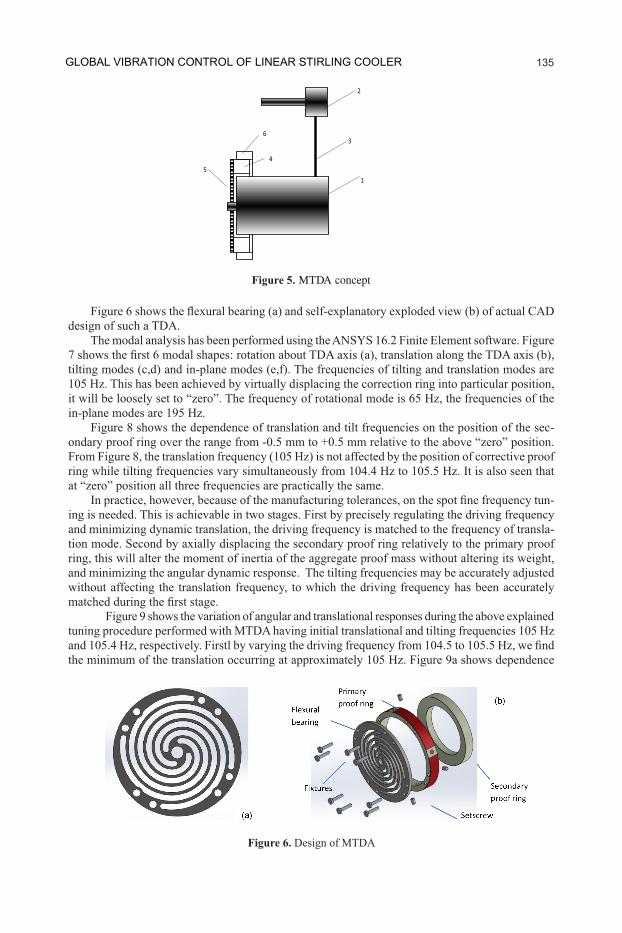
MECHANICAL DESIGN OF MUTIMODAL TDAFigure 5 shows a diagrammatic view of the side-by-side split Stirling cryogenic cooler com-
prised of compressor 1 and expander 2 interconnected by the transfer line 3, whereupon the MTDA
central anchor for mounting to compressor housing 1. The secondary proof ring 6 is coaxial and displaceable along the primary proof ring; the outer diameter of the primary ring is tightly and slidably matched to the inner diameter of the secondary proof ring. In this preferable embodiment,
In this embodiment, the translational frequency depends on the weight of the aggregate proof
frequency typical of the cryocooler.
Figure 4. Translation and tilt response of payload at different frequency detuning.
MICRO & MINIATURE 50-200K SINGLE-STAGE COOLERS 134
C19_064 7
design of such a TDA.
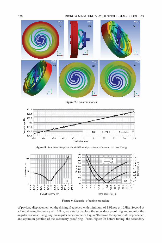
tilting modes (c,d) and in-plane modes (e,f). The frequencies of tilting and translation modes are 105 Hz. This has been achieved by virtually displacing the correction ring into particular position, it will be loosely set to “zero”. The frequency of rotational mode is 65 Hz, the frequencies of the in-plane modes are 195 Hz.
-ondary proof ring over the range from -0.5 mm to +0.5 mm relative to the above “zero” position.
ring while tilting frequencies vary simultaneously from 104.4 Hz to 105.5 Hz. It is also seen that at “zero” position all three frequencies are practically the same.
-ing is needed. This is achievable in two stages. First by precisely regulating the driving frequency and minimizing dynamic translation, the driving frequency is matched to the frequency of transla-tion mode. Second by axially displacing the secondary proof ring relatively to the primary proof ring, this will alter the moment of inertia of the aggregate proof mass without altering its weight, and minimizing the angular dynamic response. The tilting frequencies may be accurately adjusted without affecting the translation frequency, to which the driving frequency has been accurately
Figure 9 shows the variation of angular and translational responses during the above explained tuning procedure performed with MTDA having initial translational and tilting frequencies 105 Hz
the minimum of the translation occurring at approximately 105 Hz. Figure 9a shows dependence
Figure 6. Design of MTDA
1
6
45
2
3
Figure 5. MTDA concept
GLOBAL VIBRATION CONTROL OF LINEAR STIRLING COOLER 135
C19_064
of payload displacement on the driving frequency with minimum of 1.93mm at 105Hz. Second at
angular response using, say, an angular accelerometer. Figure 9b shows the appropriate dependence and optimum position of the secondary proof ring. From Figure 9b before tuning, the secondary
Figure 7. Dynamic modes
Figure 8.
Figure 9. Scenario of tuning procedure
MICRO & MINIATURE 50-200K SINGLE-STAGE COOLERS 136
C19_064 9
proof ring is displaced from the optimum position by -0.5 mm; the linear response is 1.93 mm and angular response is 51 mrad. In the optimum position the angular response is 1.2 mrad and linear response is 0.6 mm. It is interesting to note that linear response is practically independent on the axial position of the correction proof ring.
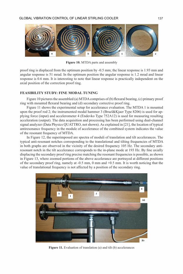
FEASIBILITY STUDY: FINE MODAL TUNING
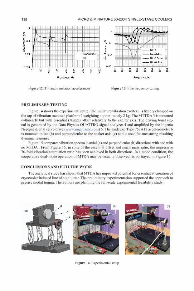
Figure 11 shows the experimental setup for accelerance evaluation. The MTDA 1 is mounted -
acceleration (output). The data acquisition and processing has been performed using dual-channel
antiresonance frequency in the module of accelerance of the combined system indicates the value of the resonant frequency of MTDA.
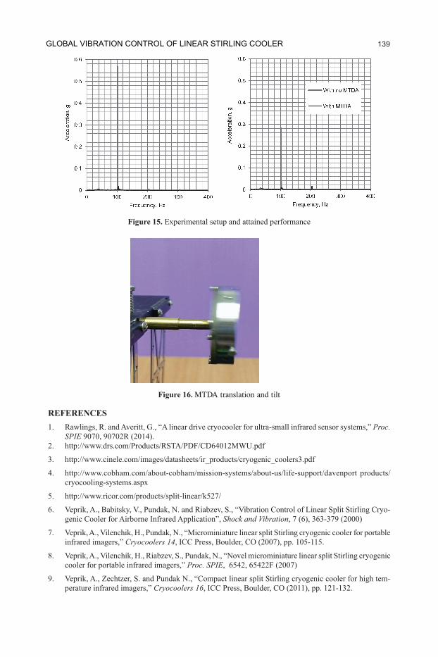
In Figure 12, the superimposed are spectra of moduli of translation and tilt accelerances. The typical anti-resonant notches corresponding to the translational and tilting frequencies of MTDA in both graphs are observed in the vicinity of the desired frequency 105 Hz. The secondary anti-
displacing the secondary proof ring precise matching the resonant frequencies is possible, as shown in Figure 13, where zoomed portions of the above accelerance are portrayed at different positions of the secondary proof ring, namely at -0.5 mm, 0 mm and +0.5 mm. It is worth noticing that the value of translational frequency is not affected by a position of the secondary ring.
Figure 10. MTDA parts and assembly
Figure 11.
GLOBAL VIBRATION CONTROL OF LINEAR STIRLING COOLER 137
C19_064 10
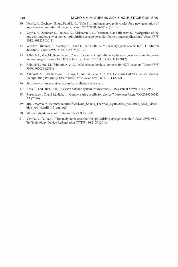
PRELIMINARY TESTING
the top of vibration mounted platform 2 weighting approximately 2 kg. The MTTDA 3 is mounted collinearly but with essential (30mm) offset relatively to the exciter axis. The driving tonal sig-
Neptune digital servo drive (www.ingeniamc.comis mounted inline (b) and perpendicular to the shaker axis (c) and is used for measuring resulting dynamic response.
Figure 15 compares vibration spectra in axial (a) and perpendicular (b) directions with and with no MTDA . From Figure 15, in spite of the essential offset and small mass ratio, the impressive 70-fold vibration attenuation ratio has been achieved in both directions. In a tuned condition, the cooperative dual-mode operation of MTDA may be visually observed, as portrayed in Figure 16.
CONCLUSIONS AND FUTUTRE WORKThe analytical study has shown that MTDA has improved potential for essential attenuation of
cryocooler induced line of sight jitter. The preliminary experimentation supported the approach to precise modal tuning. The authors are planning the full-scale experimental feasibility study.
Figure 12. Tilt and translation accelerances Figure 13. Fine frequency tuning
Figure 14.
MICRO & MINIATURE 50-200K SINGLE-STAGE COOLERS 138
C19_064 11
REFERENCESProc.
SPIE
3. http://www.cinele.com/images/datasheets/ir_products/cryogenic_coolers3.pdf
4. http://www.cobham.com/about-cobham/mission-systems/about-us/life-support/davenport products/cryocooling-systems.aspx
5. http://www.ricor.com/products/split-linear/k527/
-genic Cooler for Airborne Infrared Application”, Shock and Vibration, 7 (6), 363-379 (2000)
7. Veprik, A., Vilenchik, H., Pundak, N., “Microminiature linear split Stirling cryogenic cooler for portable infrared imagers,” Cryocoolers 14, ICC Press, Boulder, CO (2007), pp. 105-115.
cooler for portable infrared imagers,” Proc. SPIE, 6542, 65422F (2007)
9. Veprik, A., Zechtzer, S. and Pundak N., “Compact linear split Stirling cryogenic cooler for high tem-perature infrared imagers,” Cryocoolers 16, ICC Press, Boulder, CO (2011), pp. 121-132.
Figure 15.
Figure 16. MTDA translation and tilt
GLOBAL VIBRATION CONTROL OF LINEAR STIRLING COOLER 139
C19_064 1210. Veprik, A., Zechtzer, S. and Pundak N., “Split Stirling linear cryogenic cooler for a new generation of high temperature infrared imagers,” Proc. SPIE 7660, 76602K (2010).
low cost and low power tactical split Stirling cryogenic cooler for aerospace applications,” Proc. SPIE .
detectors,” Proc. SPIE
moving magnet design for HOT detectors,” Proc. SPIE
Proc. SPIE 9070, 90702P (2014)
Proc. SPIE
A1 (2014)
19. -
21. Veprik, A., Tuitto, A., "Tuned dynamic absorber for split Stirling cryogenic cooler," Proc. SPIE
MICRO & MINIATURE 50-200K SINGLE-STAGE COOLERS 140