global and local mechanical properties of autogenously...
TRANSCRIPT
Global and Local Mechanical Properties of Autogenously LaserWelded Ti-6Al-4V
XINJIN CAO, ABU SYED H. KABIR, PRITI WANJARA, JAVAD GHOLIPOUR,ANAND BIRUR, JONATHAN CUDDY, and MAMOUN MEDRAJ
Ti-6Al-4V sheets, 3.2-mm in thickness, were butt welded using a continuous wave 4 kWNd:YAG laser welding system. The effect of two main process parameters, laser power andwelding speed, on the joint integrity was characterized in terms of the joint geometry, defects,microstructure, hardness, and tensile properties. In particular, a digital image correlationtechnique was used to determine the local tensile properties of the welds. It was determined thata wide range of heat inputs can be used to fully penetrate the Ti-6Al-4V butt joints during laserwelding. At high laser power levels, however, significant defects such as underfill and porosity,can occur and cause marked degradation in the joint integrity and performance. At low weldingspeeds, however, significant porosity occurs due to its growth and the potential collapse ofinstable keyholes. Intermediate to relatively high levels of heat input allow maximization of thejoint integrity and performance by limiting the underfill and porosity defects. In considering theeffect of the two main defects on the joint integrity, the underfill defect was found to be moredamaging to the mechanical performance of the weldment than the porosity. Specifically, it wasdetermined that the maximum tolerable underfill depth for Ti-6Al-4V is approximately 6 pct ofthe workpiece thickness, which is slightly stricter than the value of 7 pct specified in AWS D17.1for fusion welding in aerospace applications. Hence, employing optimized laser processparameters allows the underfill depth to be maintained within the tolerable limit (6 pct), whichin turn prevents degradation in both the weld strength and ductility. To this end, the ability tomaintain weld ductility in Ti-6Al-4V by means of applying a high energy density laser weldingprocess presents a significant advantage over conventional arc welding for the assembly ofaerospace components.
DOI: 10.1007/s11661-013-2106-z� The Minerals, Metals & Materials Society and ASM International 2013
I. INTRODUCTION
TITANIUM alloys have been widely used in theaerospace industry due to their high specific strength andexcellent corrosion resistance.[1] As the workhorse grade of
the titanium industry, Ti-6Al-4V is an alpha–beta alloy thatis heat treatable and has a maximum service temperature of673 K (400 �C).[2] However, Ti-6Al-4V is difficult to welddue to the inherent high reactivity of titanium with atmo-spheric gases at elevated temperatures, especially in theliquid state.[3] Hence, expanding the application of Ti-6Al-4Vrequires an effective andcost-efficient joining technology.Ti-6Al-4V has been fusion welded using conventional
arc and electron beam welding technologies, and morerecently with laser welding, of which the latter offersconsiderable promise due to an interesting combinationof some characteristics, including manufacturing flexi-bility (e.g. non-vacuum, local shielding gas protection),high energy density, low heat input, high welding speed,narrow size of the fusion and heat affected zones (HAZ),and low weld distortion.[4] Similar to the electron beam,the laser beam is a line-shaped heating source throughthe joint thickness, as compared to a point heatingsource for conventional arc welding,[5] but without thedisadvantage of a confined environment for vacuumprotection. Laser welding also produces a fusion zone(FZ) microstructure that comprises of small prior-bgrains (due to the rapid solidification at low heat input)that are similar in size to that observed in electron beamweldments, but considerably finer than those in conven-tional arc welds.[6] In addition, laser welding has theflexibility for welding autogenously or with filler wire
XINJIN CAO, Senior Research Officer, is with the Structures,Materials and Manufacturing Laboratory, National Research CouncilCanada - Aerospace, 5145 Decelles Avenue, Montreal, QC H3T 2B2,Canada, and also Adjunct Professor, with the Department ofMechanical and Industrial Engineering, Concordia University, 1455De Maisonneuve Blvd. West, Montreal, QC H3G 1M8, Canada.Contact e-mail: [email protected] ABU SYED H. KABIR,formerly Master Graduate Student, with the Structures, Materials andManufacturing Laboratory, National Research Council Canada -Aerospace, also with the Department of Mechanical and IndustrialEngineering, Concordia University, is now Ph.D. Candidate with theMcGill University, Montreal, QC H3A 0C5, Canada. PRITIWANJARA, Team Leader, and JAVAD GHOLIPOUR, SeniorResearch Officer, are with the Structures, Materials and Manufactur-ing Laboratory, National Research Council Canada - Aerospace.ANAND BIRUR and JONATHAN CUDDY, Senior Engineers, arewith the StandardAero Limited, 33 Allen Dyne Road, Winnipeg, MBR3H 1A1, Canada. MAMOUN MEDRAJ, Professor, is with theDepartment of Mechanical and Industrial Engineering, ConcordiaUniversity.
The following statement pertains only to authors X. Cao, A.S.H.Kabir, and P. Wanjara: Published with permission of the Crown inRight of Canada, i.e., the Government of Canada.
Manuscript submitted June 13, 2013.
METALLURGICAL AND MATERIALS TRANSACTIONS A

addition.[7] Effective shielding gas protection remains animportant criterion for laser welding, but the lowerenergy and shorter welding time as compared to arcwelding mitigate contamination of the molten weld poolfrom atmospheric elements, allowing improved ductilityfor the joints assembled with the former process.[6]
To this end, as part of a larger program on theadvanced manufacturing of aerospace materials at theNational Research Council of Canada (NRC) theweldability of Ti-6Al-4V was investigated using acontinuous wave (CW) 4 kW Nd:YAG laser system,the findings of which were reported previously inReferences 8 through 11. Of importance to the under-standing of the joint integrity is characterization of themechanical response of the weldment. Although theglobal or overall mechanical properties provide usefulinformation for the welded assembly, the constitutivedata for the different microstructural zones that com-prise the ‘‘composite’’ structure of the weldment, i.e.,base metal (BM), HAZ and FZ, is important forevaluating whether the local mechanical response canmeet the stress requirements in the service environment.To date, the local mechanical properties of friction stirwelded aluminum alloys[12,13] and laser welded 304Lstainless steel[14] have been investigated using an optical,full-field displacement measurement or digital imagecorrelation (DIC) technique. Recently, the presentauthors have also evaluated the local mechanical prop-erties of laser welded Ti-6Al-4V using DIC.[8,11] In thiswork, the optimal parametric window for the laserwelding process was established through evaluating theglobal and local mechanical properties and response ofthe Ti-6Al-4V weldments to have a better insight on theprocessing-structure–property interrelationship.
II. EXPERIMENTAL PROCEDURE
The sheet material used in this study was mill-annealed Ti-6Al-4V (Grade 5 titanium) with a nominalthickness of 3.2 mm. The samples were machined andhad dimensions of 102 mm in length 9 63 mm in width.All welds were butt joints with no intentional gap andwere welded along the sample length, which wasperpendicular to the rolling direction. The faying andjoining surfaces of all the samples were brushed andthen cleaned with ethanol to remove any surface oxidesand contaminants prior to clamping and welding. Thewelding equipment used was a 4 kW CW solid-stateNd:YAG laser system equipped with an ABB robot anda magnetic holding fixture. A collimation lens of200 mm, a focal lens of 150 mm and a fiber diameterof 0.6 mm were employed to produce a focal spotdiameter of about 0.45 mm. The top surface of theworkpiece was shielded using high purity argon gas at aflow rate of 23.6 L/min (50 cfh), while the bottomsurface and the trail on the top surface were shieldedusing a mixture of argon and helium (50 to 50 in vol pct)gases at a total flow rate of 66.1 L/min (140 cfh). Thelaser beam was focused at 1 mm under the top surface ofthe workpiece. Table I gives the laser welding processparameters (laser power, welding speed, heat input, and
power density) used in this study. The experiments weredesigned in a way to have a specific heat input usingdifferent combinations of the two main parameters(laser power and welding speed). It is noteworthy thatthe upper limit of the welding speed at a given laserpower is bound by the presence of a lack-of-penetration(LOP) defect.Three specimens were taken from the stable middle
region of each joint for metallographic examination andmicrohardness evaluation. The specimens were thenmounted, ground, polished, and etched by immersion inKroll’s reagent (1 to 3 mL HF+2 to 6 mL HNO3+100 ml H2O) for 6 to 10 seconds. Microstructuralexamination was carried out using an inverted opticallight microscope (Olympus GX71) equipped with Ana-lySIS Five digital image analysis software that allowedquantitative measurements of the defect size and frac-tion. Vickers micro-indentation hardness was measuredat a load of 500 g, a dwell period of 15 seconds and, inaccordance with ASTM E384-05, an indent interval of0.2 mm[11] using a Struers Duramin A-300 machine.Four tensile coupons having a standard sub-size
geometry of 25 mm in gauge length, 6 mm in width,and 3.2 mm in thickness were machined in accordanceto ASTM E8M-04.[15] All the tensile coupons weretested at room temperature and a constant crossheadrate of 2 mm/min using a 250 kN MTS testing frameequipped with a laser video extensometer. To evaluatethe local tensile behavior for selected process conditions,an ARAMIS DIC system (GOM), as described inReference 11, was also utilized during tensile testing. Itis noteworthy that before executing the tensile tests, thefront side of each coupon was painted with a high-contrast random pattern of black speckles on a whitebackground, while on the back side two pieces of lasertape were attached to mark the gauge length for the laserextensometer during testing. To determine the localtensile properties, an iso-stress condition (e.g., the sameglobal tensile stress at all locations in the gauge length)was assumed for the analysis of tensile results as widelyused for different alloys.[12,13,16] The local strain datawere then extracted from the DIC system for regions ofinterest within the gauge length and plotted against thecorresponding global stress data to generate the localstress–strain response. Once the stress–strain diagramfor a given location was generated, the correspondinglocal tensile properties, including the yield stress andplastic strain at fracture were determined.
III. RESULTS AND DISCUSSION
A. Weld Bead Geometry
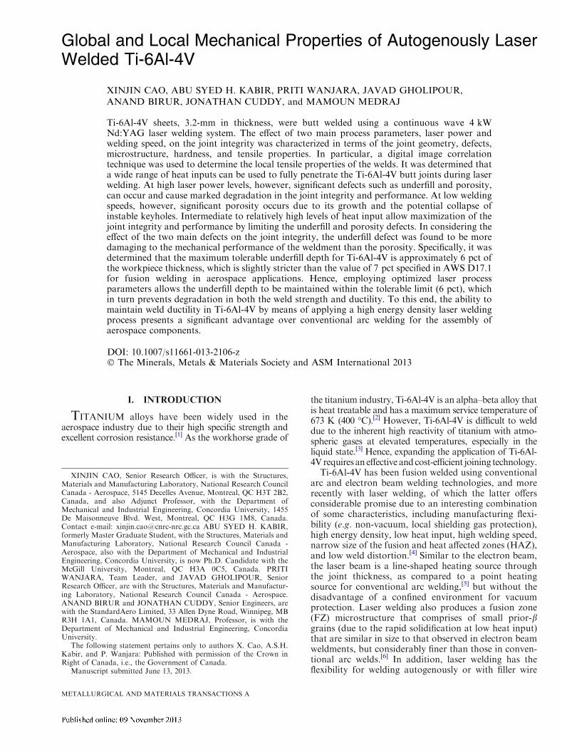
Figure 1 shows the transverse sections of all the jointsobtained using different laser process conditions withthe objective of achieving full penetration across thejoint thickness of 3.2 mm. The upper limit of thewelding speed at a given laser power is determined bythe presence of LOP defects. For example, at a laserpower of 3 kW, the maximum welding speed is 3.38 m/min, since a LOP defect was observed at 4.5 m/min
METALLURGICAL AND MATERIALS TRANSACTIONS A
(other welds with LOP defects obtained at 2 and 4 kWand their respective higher welding speeds are not shownhere). It is noteworthy that this weld (3 kW, 4.5 m/min)was then welded again from the opposite side using thesame processing parameters for full penetration; allresults related to this joint are taken from the single-sided weld with a LOP except for the global and localtensile properties that were obtained from the double-sided weld.
With increasing laser power, the range of weldingspeeds that permitted full penetration increased. Forexample, at laser powers of 2, 3, and 4 kW, fullypenetrated welds were obtained at welding speeds ofapproximately 0.75 to 1.50 m/min, 1.13 to 3.38 m/min,and 3.0 to 7.5 m/min, respectively. Therefore, a widerprocess window can be obtained at a higher laser power.Furthermore, it was determined that at a higher laserpower, a lower heat input is needed for full penetration.For instance, the minimum heat inputs for full penetra-tion with a single welding pass are about 80 J/mm at alaser power of 2 kW, 53 J/mm at 3 kW, and 32 J/mm at4 kW. Therefore, a higher laser power can reduce theminimum heat input required for full penetration acrossa specific thickness.
Although a range of process conditions can achievefull penetration across the joint thickness, the weld beadgeometry can vary considerably even when a similarheat input is used. For instance, at a heat input of 80 J/mm, full penetration across the joints was obtained forthree different laser power and welding speed combina-tions, i.e., at low (2 kW and 1.50 m/min), medium(3 kW and 2.25 m/min), and high (4 kW and 3.0 m/min) levels. However, as revealed in Figure 1, theintermediate process condition (3 kW, 2.25 m/min)results in a relatively better weld bead geometry andweld integrity, as remarked from the extent of theunderfill depth and the porosity level (as discussed indetail in the next section) in the welds assembled at 4and 2 kW, respectively. As apparent from Figure 1, withincreasing heat input (or decreasing welding speed at agiven laser power), both the FZ and HAZ sizes increase.Also with increasing heat input, the weld bead geometryevolves from a V-shape to an hourglass morphology andthen to a wide near-rectangular profile, which reflects
the evolution in welding mode from keyhole to ‘‘near-conduction’’ that imparts a marked increase in the heatinput and thus renders a large weld bead profile.
B. Weld Defects
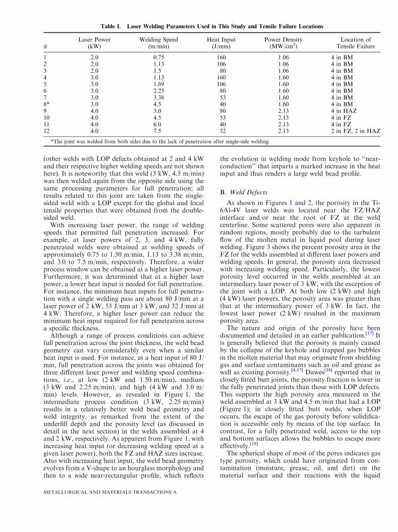
As shown in Figures 1 and 2, the porosity in the Ti-6Al-4V laser welds was located near the FZ/HAZinterface and/or near the root of FZ at the weldcenterline. Some scattered pores were also apparent inrandom regions, mostly probably due to the turbulentflow of the molten metal in liquid pool during laserwelding. Figure 3 shows the percent porosity area in theFZ for the welds assembled at different laser powers andwelding speeds. In general, the porosity area decreasedwith increasing welding speed. Particularly, the lowestporosity level occurred in the welds assembled at anintermediary laser power of 3 kW, with the exception ofthe joint with a LOP. At both low (2 kW) and high(4 kW) laser powers, the porosity area was greater thanthat at the intermediary power of 3 kW. In fact, thelowest laser power (2 kW) resulted in the maximumporosity area.The nature and origin of the porosity have been
documented and detailed in an earlier publication.[17] Itis generally believed that the porosity is mainly causedby the collapse of the keyhole and trapped gas bubblesin the molten material that may originate from shieldinggas and surface contaminants such as oil and grease aswell as existing porosity.[4,17] Dawes[18] reported that inclosely fitted butt joints, the porosity fraction is lower inthe fully penetrated joints than those with LOP defects.This supports the high porosity area measured in theweld assembled at 3 kW and 4.5 m/min that had a LOP(Figure 1); in closely fitted butt welds, when LOPoccurs, the escape of the gas porosity before solidifica-tion is accessible only by means of the top surface. Incontrast, for a fully penetrated weld, access to the topand bottom surfaces allows the bubbles to escape moreeffectively.[18]
The spherical shape of most of the pores indicates gastype porosity, which could have originated from con-tamination (moisture, grease, oil, and dirt) on thematerial surface and their reactions with the liquid
Table I. Laser Welding Parameters Used in This Study and Tensile Failure Locations
#Laser Power
(kW)Welding Speed
(m/min)Heat Input(J/mm)
Power Density(MW/cm2)
Location ofTensile Failure
1 2.0 0.75 160 1.06 4 in BM2 2.0 1.13 106 1.06 4 in BM3 2.0 1.5 80 1.06 4 in BM4 3.0 1.13 160 1.60 4 in BM5 3.0 1.69 106 1.60 4 in BM6 3.0 2.25 80 1.60 4 in BM7 3.0 3.38 53 1.60 4 in BM8* 3.0 4.5 40 1.60 4 in BM9 4.0 3.0 80 2.13 4 in HAZ10 4.0 4.5 53 2.13 4 in FZ11 4.0 6.0 40 2.13 4 in FZ12 4.0 7.5 32 2.13 2 in FZ, 2 in HAZ
*The joint was welded from both sides due to the lack of penetration after single-side welding.
METALLURGICAL AND MATERIALS TRANSACTIONS A

metal.[19,20] Hydrogen, adsorbed in the molten weld poolthat cannot escape before solidification, is considered tobe mainly responsible for the formation of gas pores intitanium alloys,[20] particularly because the solubility ofhydrogen increases with decreasing temperature inliquid titanium.[21] The molten metal near the immediatevicinity of the keyhole has the highest temperature
(evaporation point) and it decreases progressively to themelting point at the fusion boundary; the solubility ofhydrogen is thus more supersaturated at the weld centerand tends to diffuse towards the fusion boundary, whichexplains the presence of hydrogen porosity at the FZ/HAZ interface. Also as liquid titanium has a highersolubility for hydrogen than solid titanium at the
Heat input 2 kW 3 kW 4 kW
160 J/mm
0.75 m/min 1.13 m/min
106 J/mm
1.13 m/min 1.69 m/min
80 J/mm
1.50 m/min 2.25 m/min 3.0 m/min
53 J/mm
3.38 m/min 4.5 m/min
40 J/mm
4.5 m/min 6 m/min
32 J/mm
7.5 m/min
Fig. 1—Images of transverse weld sections obtained at various heat inputs.
METALLURGICAL AND MATERIALS TRANSACTIONS A
melting temperature,[22] the centerline region of the weldpool is usually enriched in hydrogen; hydrogen gas canthus accumulate at the weld centerline, which is the lastpart of liquid/solid interface to solidify. Without aneffective means for escape, due to the low temperaturesat this late stage of solidification, the accumulatedhydrogen gas is entrapped and leads to the higheramount of porosity at the centerline.[23] It is noteworthythat though the centerline porosity is formed due to theevolution of hydrogen at the liquid/solid interface, theporosity in the root area can also be related to theinstability of the keyhole.[24]
The evolved hydrogen can form porosity by nucle-ation or direct diffusion into discontinuities or existingpores. Then these pores can grow and coalesce.[22,25] Ata low welding speed, the weld pool remains in the liquidstate for a longer time, and thus the gas porosity caneffectively grow. As a consequence, the porosity areawould tend to decrease with increasing welding speedfor a given laser power, which validates the observationsin the present work (Figure 3). Specifically, both largerpores and higher porosity areas were apparent at higher
heat inputs due to the longer time available for thegrowth and coalescence of the voids. It was remarkedthat the porosity area was significantly greater for the2 kW laser power conditions, particularly at the lowestwelding speed of 0.75 m/min. These pores are mainlylocated in the lower part of the FZ (near weld root), asindicated in Figure 1. This is probably due to therelatively slow cooling rate associated with this lowestwelding speed and the potential instability of thekeyhole under such conditions. In particular, keyholestability can only be achieved at high welding speeds[26]
and, for laser welding of Ti-6Al-4V with filler wireaddition, the formation of significant porosity due to aninstable keyhole was reported at welding speeds lessthan 1 m/min.[17] In spite of the high welding speeds forthe 4 kW laser power conditions, high porosity areavalues were also observed, as shown in Figures 1 and 3.The use of a high laser power can slightly decrease thecooling rate and thus favor the growth of gas porosity,but the formation of evaporative porosity, caused bythe high power density, is probably the main reason forthe high porosity area as observed in this case.[17]
Hence, a reasonable combination of welding speed withan intermediate laser power (3 kW) can render mini-mized porosity, as illustrated in Figure 3. Though theexistence of the porosity in the Ti-6Al-4V laser weldscan reduce the load-bearing area and the mechanicalproperties of the joints, the total percent porosity wastypically less than 1 pct of the FZ area (Figure 3).Hence, the characteristics of the underfill defect, thatappears more prevalent in the images of the weld beads(Figure 1), may be more critical to the mechanicalperformance.As shown in Figure 1, the underfill defects appear in
all the Ti-6Al-4V laser welds, especially on the topsurface and, at low welding speeds on the root surfacealso. Figure 4 illustrates the effect of the welding speedand power density on the underfill depth and area.According to AWS D17.1,[27] the specification for fusionwelding for aerospace applications stipulates a maxi-mum underfill depth of 0.07T (where T is the thicknessor 3.2 mm in the present work) for Class A welds.Hence, over the range of welding conditions examined,
Fig. 2—Typical porosity or pore clusters obtained at a low laser power of 2 kW and welding speeds of (a) 0.75 m/min and (b) 1.13 m/min.
Fig. 3—Effect of laser power and welding speed on the porosity area(the arrow identifies the weld with a LOP that was then welded fromboth sides).
METALLURGICAL AND MATERIALS TRANSACTIONS A

the Ti-6Al-4V laser welds satisfy Class A requirements ifthe underfill discontinuity is below 0.22 mm, as indi-cated by the dashed line in Figure 4(a). At laser powersof 2 and 3 kW, all the welds remained within theacceptable specification. However, at a laser power of4 kW, the maximum underfill depth just meets theacceptable threshold at the lower welding speeds (higherheat inputs); with increasing welding speed (decreasingheat input) the maximum underfill depth rapidlyincreases to more than twice the acceptable thresholdvalue. For each laser power level, the maximumunderfill depth increases linearly with increasing weldingspeed for all fully penetrated joints (Figure 4(a)).
As the formation of underfill defects is mainly due tothe evaporation and expulsion of molten materials,[28]
the total underfill area increases with increasing laserpower density, as shown in Figure 4(b). Specifically, asthe laser power density increases, the total vaporizationlosses increase significantly.[29,30] At higher heat input(i.e. higher laser power or lower welding speed), theextent of evaporation is greater.[31] If the weld pooltemperature is very high, then the escaping vapor mayexert a large recoil force on the weld pool surface. Whenthe vapor recoil force exceeds the surface tension force
of the liquid metal at the periphery of the weld pool,liquid metal expulsion or ejection can occur.[29,30] Thehigher vapor pressure will cause greater expulsion of theliquid metal,[32] which will eject at an increasing velocitywith increasing laser power density. Both the size of theliquid droplets and size distributions of the expelledparticles have been reported to increase with increasingpower density.[29,30]
As a higher welding speed allows lesser interactiontime between the laser beam and the workpiece material,the weld pool temperature and recoil force pressureshould be lower, and, therefore, the material losses fromevaporation and expulsion are also lower. However, asillustrated in Figure 4(a), the maximum underfill depthincreases linearly with increasing welding speed for allfully penetrated welds; this suggests that the highercooling rates associated with the higher welding speedsplay a vital role in the formation of the underfill defects.This is probably related to the flow of the molten metal.In particular, at higher welding speeds and the associ-ated faster cooling rates, the molten metal has a shortertime to solidify and fill the surface grooves/cavities.[28]
Thus, the extremely large underfill depths, as observedat the high laser power of 4 kW and high welding speedsof 6.0 to 7.5 m/min, are due to the combined effects of(i) failure to fill the surface grooves at the high coolingrate conditions and (ii) significant evaporation andejection of the liquid metal at the high laser powerdensities. These underfill defects can reduce the thick-ness and thus the load-bearing capacity of the weldregion, thereby causing significant stress or strainconcentration and favoring the initiation of cracks,which can heavily degrade the mechanical properties.[17]
The influence of these underfill defects on the mechan-ical performance of the Ti-6Al-4V laser welds will bediscussed in greater detail in the section on the tensileproperties.In addition to the two main defects, underfill and
porosity, as discussed above, overlap defects were alsoobserved, but only at the high laser power of 4 kW, asshown in Figures 1 and 5. This is due to theoccurrence of high recoil force pressures at the highlaser power densities. The overlap defects also lead tothe formation of a lack of bonding (LOB) between theoverlapped liquid metal and the relatively cold work-piece surface. This defect can work as a stressconcentrator in the welded joints and thus should beavoided during manufacturing. Notwithstanding itsprospective for low heat inputs and high weldingspeeds, a laser power of 4 kW is a non-conduciveparametric condition for laser welding of 3.2-mm thickTi-6Al-4V as it results in overlap and inacceptableunderfill defects.
C. Micro-indentation Hardness and MicrostructuralEvolution
Figure 6 shows the typical hardness profiles measuredat the top, middle, and root regions of a welded jointassembled at 3 kW and 1.69 m/min. For each weld, thelowest and highest hardness values occurred in the BMand FZ, respectively. The average hardness in the BM
Fig. 4—Effect of (a) welding speed and (b) the power density on theunderfill dimensions (the arrow identifies the weld with a LOP thatwas then welded from both sides).
METALLURGICAL AND MATERIALS TRANSACTIONS A

was 312 ± 8 HV. In the FZ of the weld assembled at alaser power of 3 KW and a welding speed of 1.69 m/min, the average hardness was 360 ± 4 HV, roughly15 pct greater. The hardness evolution across theweldment can be related to the transformation of themicrostructural constituents, namely the a and b phasesin Ti-6Al-4V, which have transpired due to the thermalhistory imparted by the laser welding process, as shownin Figure 7. Specifically, the as-received microstructureof the mill annealed Grade 5 Ti-6Al-4V consisted ofequiaxed a with intergranular b, as revealed in Fig-ure 7(a). During laser welding, the temperature in theFZ exceeds the liquidus temperature of Ti-6Al-4V. Assuch, the FZ macrostructure of the Ti-6Al-4V laserwelds (Figure 1) consisted of columnar prior-b grainsthat epitaxially grow in a direction opposite to that ofthe heat flow,[17] i.e. from the semi-melted b grainsadjacent to the fusion boundary towards the weldcenterline where impingement occurs upon solidifica-tion. Within the prior-b grains, the microstructure of the
FZ appeared to consist of both diffusionless anddiffusional transformation structures. Specifically, theacicular microstructure in FZ (Figure 7(e)) appears topredominately consist of martensite (a¢), a supersatu-rated non-equilibrium hexagonal a phase produced fromthe diffusionless transformation of the high temperatureb phase[1,33] during rapid cooling associated with laserwelding. It is noteworthy that as vanadium suppressesthe start of the a¢ transformation to below ambienttemperature, the microstructure in the FZ may alsocontain evidence of remnant b.[1] It has been reportedthat cooling rates in excess of 683 K/s (410 �C/s) aretypically needed for the b phase of Ti-6Al-4V to fullytransform to a¢.[34] Though the high self-quench rateassociated with the laser welding process indubitablypromotes diffusionless transformation of the b phase toa¢, the presence of a along some of the prior-b grainboundaries (Figure 7(f)) indicates that the cooling rate isclose to the lower limit of the cooling rate for a¢formation, i.e., 683 K/s (410 �C/s). Previously, for laser
(a) (b)
Overlap
Fig. 5—Typical overlap and lack of bonding (a) 4 kW, 3.0 m/min, and (b) 4 kW, 6.0 m/min.
200
300
400
500
-8 -6 -4 -2 0 2 4 6 8
HV
500
gf
Distance from center (mm)
BM BMFZ HAZHAZ
Top
Middle
Root
Fig. 6—Typical hardness distribution obtained for the Ti-6Al-4V laser weld assembled at 3 kW and 1.69 m/min.
METALLURGICAL AND MATERIALS TRANSACTIONS A
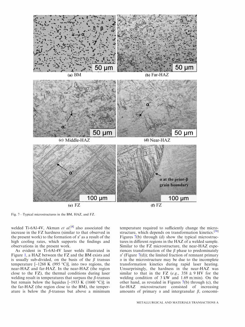
welded Ti-6Al-4V, Akman et al.[4] also associated theincrease in the FZ hardness (similar to that observed inthe present work) to the formation of a¢ as a result of thehigh cooling rates, which supports the findings andobservations in the present work.
As evident in Ti-6Al-4V laser welds illustrated inFigure 1, a HAZ between the FZ and the BM exists andis usually sub-divided, on the basis of the b transustemperature [~1268 K (995 �C)], into two regions, thenear-HAZ and far-HAZ. In the near-HAZ (the regionclose to the FZ), the thermal conditions during laserwelding result in temperatures that surpass the b-transusbut remain below the liquidus [~1933 K (1660 �C)]; inthe far-HAZ (the region close to the BM), the temper-ature is below the b-transus but above a minimum
temperature required to sufficiently change the micro-structure, which depends on transformation kinetics.[38]
Figures 7(b) through (d) show the typical microstruc-tures in different regions in the HAZ of a welded sample.Similar to the FZ microstructure, the near-HAZ expe-riences transformation of the b phase to predominatelya¢ (Figure 7(d)); the limited fraction of remnant primarya in the microstructure may be due to the incompletetransformation kinetics during rapid laser heating.Unsurprisingly, the hardness in the near-HAZ wassimilar to that in the FZ (e.g., 358 ± 9 HV for thewelding condition of 3 kW and 1.69 m/min). On theother hand, as revealed in Figures 7(b) through (c), thefar-HAZ microstructure consisted of increasingamounts of primary a and intergranular b, concomi-
Fig. 7—Typical microstructures in the BM, HAZ, and FZ.
METALLURGICAL AND MATERIALS TRANSACTIONS A
tantly with a decreasing fraction of a¢. Specifically,traversing from the near-HAZ to the BM, the fraction ofa¢ in the microstructure decreases rapidly from nearly100 pct to zero and, as a consequence, a sharp decreasein hardness transpires in this region.
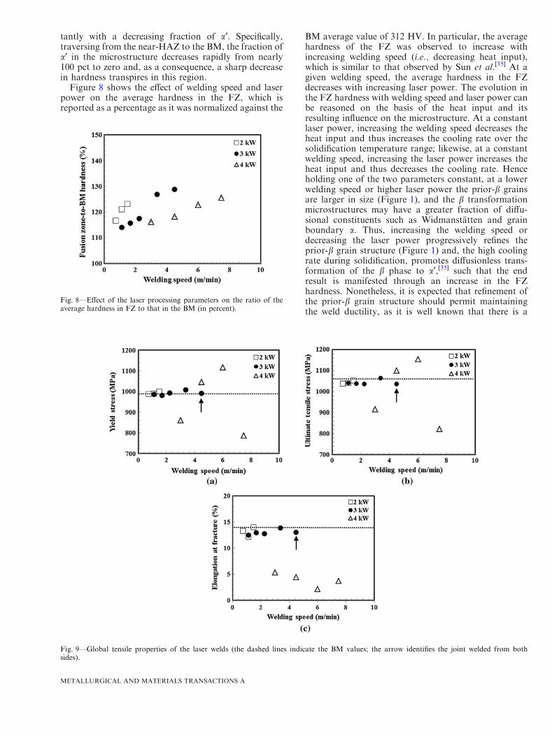
Figure 8 shows the effect of welding speed and laserpower on the average hardness in the FZ, which isreported as a percentage as it was normalized against the
BM average value of 312 HV. In particular, the averagehardness of the FZ was observed to increase withincreasing welding speed (i.e., decreasing heat input),which is similar to that observed by Sun et al.[35] At agiven welding speed, the average hardness in the FZdecreases with increasing laser power. The evolution inthe FZ hardness with welding speed and laser power canbe reasoned on the basis of the heat input and itsresulting influence on the microstructure. At a constantlaser power, increasing the welding speed decreases theheat input and thus increases the cooling rate over thesolidification temperature range; likewise, at a constantwelding speed, increasing the laser power increases theheat input and thus decreases the cooling rate. Henceholding one of the two parameters constant, at a lowerwelding speed or higher laser power the prior-b grainsare larger in size (Figure 1), and the b transformationmicrostructures may have a greater fraction of diffu-sional constituents such as Widmanstatten and grainboundary a. Thus, increasing the welding speed ordecreasing the laser power progressively refines theprior-b grain structure (Figure 1) and, the high coolingrate during solidification, promotes diffusionless trans-formation of the b phase to a¢,[35] such that the endresult is manifested through an increase in the FZhardness. Nonetheless, it is expected that refinement ofthe prior-b grain structure should permit maintainingthe weld ductility, as it is well known that there is a
Fig. 8—Effect of the laser processing parameters on the ratio of theaverage hardness in FZ to that in the BM (in percent).
Fig. 9—Global tensile properties of the laser welds (the dashed lines indicate the BM values; the arrow identifies the joint welded from bothsides).
METALLURGICAL AND MATERIALS TRANSACTIONS A
propensity for crack propagation along the prior-b grainboundaries.[6]
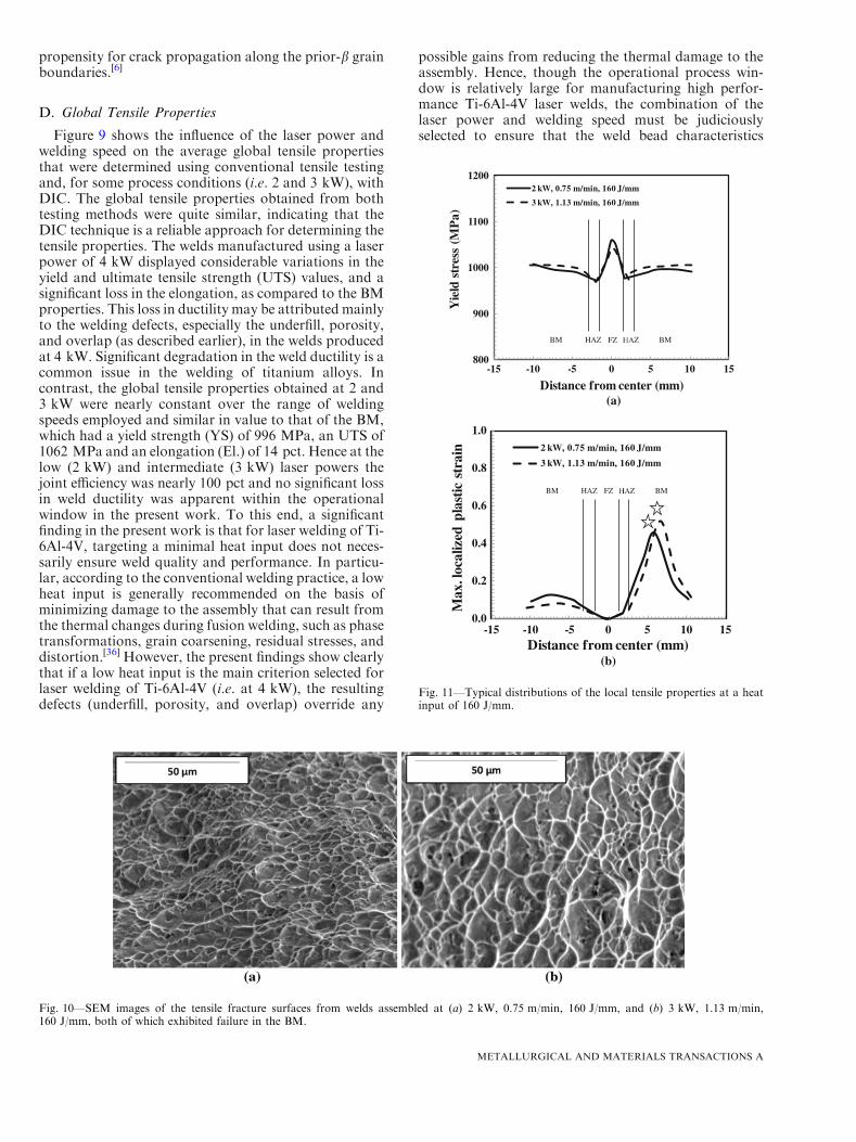
D. Global Tensile Properties
Figure 9 shows the influence of the laser power andwelding speed on the average global tensile propertiesthat were determined using conventional tensile testingand, for some process conditions (i.e. 2 and 3 kW), withDIC. The global tensile properties obtained from bothtesting methods were quite similar, indicating that theDIC technique is a reliable approach for determining thetensile properties. The welds manufactured using a laserpower of 4 kW displayed considerable variations in theyield and ultimate tensile strength (UTS) values, and asignificant loss in the elongation, as compared to the BMproperties. This loss in ductility may be attributed mainlyto the welding defects, especially the underfill, porosity,and overlap (as described earlier), in the welds producedat 4 kW. Significant degradation in the weld ductility is acommon issue in the welding of titanium alloys. Incontrast, the global tensile properties obtained at 2 and3 kW were nearly constant over the range of weldingspeeds employed and similar in value to that of the BM,which had a yield strength (YS) of 996 MPa, an UTS of1062 MPa and an elongation (El.) of 14 pct. Hence at thelow (2 kW) and intermediate (3 kW) laser powers thejoint efficiency was nearly 100 pct and no significant lossin weld ductility was apparent within the operationalwindow in the present work. To this end, a significantfinding in the present work is that for laser welding of Ti-6Al-4V, targeting a minimal heat input does not neces-sarily ensure weld quality and performance. In particu-lar, according to the conventional welding practice, a lowheat input is generally recommended on the basis ofminimizing damage to the assembly that can result fromthe thermal changes during fusion welding, such as phasetransformations, grain coarsening, residual stresses, anddistortion.[36] However, the present findings show clearlythat if a low heat input is the main criterion selected forlaser welding of Ti-6Al-4V (i.e. at 4 kW), the resultingdefects (underfill, porosity, and overlap) override any
possible gains from reducing the thermal damage to theassembly. Hence, though the operational process win-dow is relatively large for manufacturing high perfor-mance Ti-6Al-4V laser welds, the combination of thelaser power and welding speed must be judiciouslyselected to ensure that the weld bead characteristics
(a)
(b)
800
900
1000
1100
1200
-15 -10 -5 0 5 10 15
Yie
ld s
tres
s (M
Pa)
Distance from center (mm)
2 kW, 0.75 m/min, 160 J/mm
3 kW, 1.13 m/min, 160 J/mm
0.0
0.2
0.4
0.6
0.8
1.0
-15 -10 -5 0 5 10 15
Max
. loc
aliz
ed p
last
ic s
trai
n
Distance from center (mm)
2 kW, 0.75 m/min, 160 J/mm
3 kW, 1.13 m/min, 160 J/mm
BM BMHAZ HAZFZ
BM BMHAZ HAZFZ
Fig. 11—Typical distributions of the local tensile properties at a heatinput of 160 J/mm.
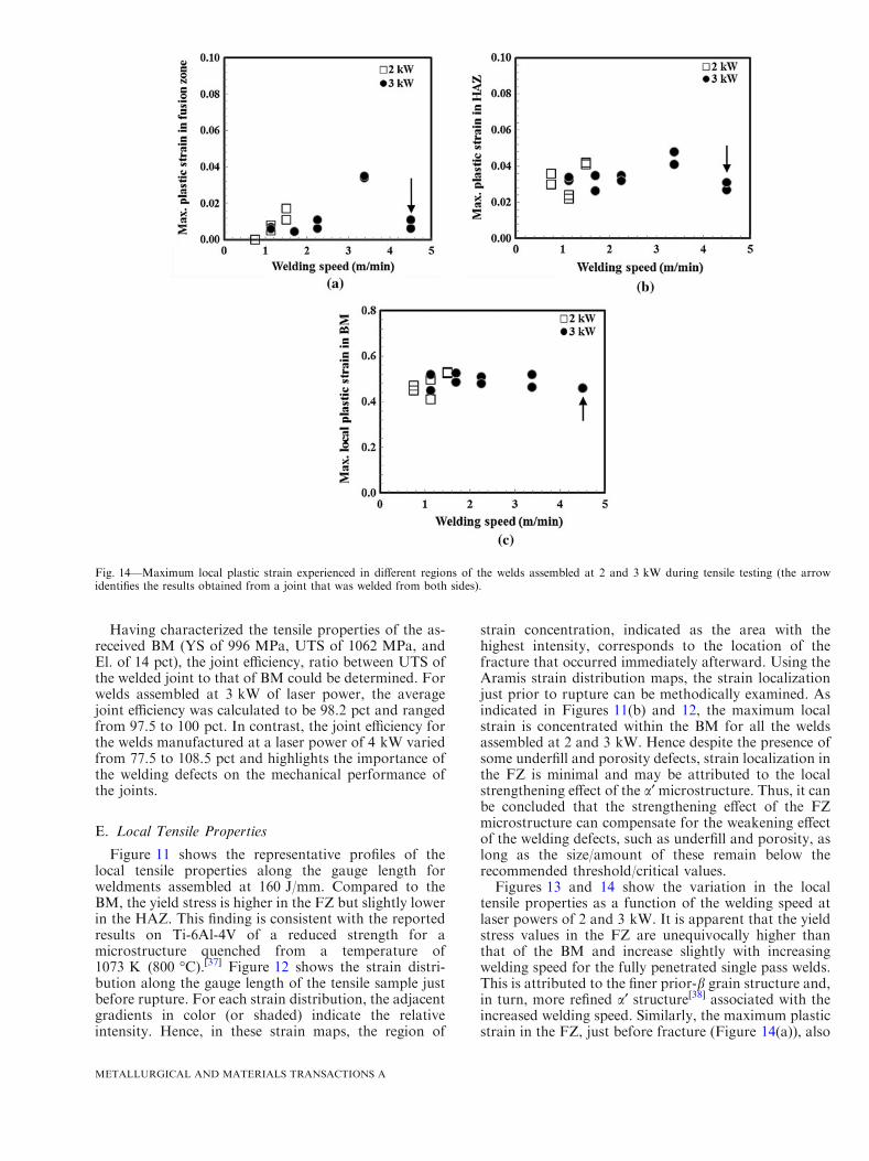
Fig. 10—SEM images of the tensile fracture surfaces from welds assembled at (a) 2 kW, 0.75 m/min, 160 J/mm, and (b) 3 kW, 1.13 m/min,160 J/mm, both of which exhibited failure in the BM.
METALLURGICAL AND MATERIALS TRANSACTIONS A

2 kW, 0.75 m/min, 160 J/mm
2 kW, 1.13 m/min, 106 J/mm
2 kW, 1.5 m/min, 80 J/mm
3 kW, 1.13 m/min, 160 J/mm
3 kW, 1.69 m/min, 106 J/mm
3 kW, 2.25 m/min, 80 J/mm
3 kW, 3.38 m/min, 53 J/mm
FZHAZHAZ
FZHAZHAZ
FZHAZHAZ
FZHAZHAZ
FZHAZHAZ
FZHAZHAZ
FZHAZHAZ
3 kW, 4.50 m/min, 40 J/mm
FZHAZHAZ
Fig. 12—Strain maps just before rupture of the tensile samples.
METALLURGICAL AND MATERIALS TRANSACTIONS A

exhibit minimum levels of welding defects such asunderfill and porosity. In the case of 3.2-mm-thick Ti-6Al-4V, low (2 kW) and intermediate (3 kW) laserpowers with the fastest welding speed that can allowcomplete penetration appear to result in the highmechanical performance with no loss in both strengthand ductility, as illustrated in Figure 9.
As shown in Table I, failure of all the weldsmanufactured at 2 and 3 kW occurred in the BM,while the welds joined at 4 kW failed in either theHAZ or FZ. It is interesting to note that this behaviorin the tensile failure for the 3.2-mm-thick welds, asobtained in the present work, is consistent with earlierresults on 5.1-mm-thick Ti-6Al-4V laser welds.[8] Inparticular, tensile failure is predominantly triggered bythe main welding defects, such as underfill and poros-ity. The initiation of cracking is controlled by theunderfill defect while its propagation is determined bythe porosity level. Cracks usually form at the underfilldefect if its depth exceeds the threshold value, which isapproximately 6 pct of the workpiece thickness. Thecracks can then propagate through the FZ at a highlevel of porosity, or through the HAZ at a low level ofporosity. If both the underfill depth and porosity levelare low, the weld region comprising the FZ and HAZappears to be stronger than the BM and thus failureusually appears in the latter.[8] This can be substanti-ated for the 3.2-mm-thick Ti-6Al-4V welds manufac-
tured at 2 and 3 kW, which exhibited tensile failure inthe BM and had underfill depth values (0.04 to0.19 mm) that were lower than the threshold (Fig-ure 4(a)). Failure in BM for these welds can bereasoned on the basis of a high weld integrity (smallunderfill depth and low porosity) and a strong FZ (e.g.,high hardness) microstructure (a¢). The typical tensilefracture surfaces, as shown in Figure 10, reveal cupand cone shape configurations with copious dimples ormicrovoids, which are indicative of ductile failure. It isalso noteworthy that the appearance of some pores inFZ especially for the 2 kW welds does not lead to anydegradation in the global tensile properties, includingductility, and may be attributed to the low porositylevel (less than 1 pct of the FZ area) and the relativelyround shape of the pores. In contrast, for the weldsmanufactured at a laser power of 4 kW, the underfilldepth was at or above the threshold value of 0.22 mmand, for some welds, the porosity in the FZ (Figure 3)was also relatively high (e.g. 0.5 pct). Hence, the effectof the strong FZ microstructure (a¢) is overridden bythe welding defects that control the fracture duringtensile loading. This present study also reinforces theuse of a lower maximum tolerable underfill depth ofabout 6 pct of the workpiece thickness, which isslightly stricter than the existing 7 pct thresholdaccording to the aerospace specification for fusionwelding (AWS D17.1).[27]
Fig. 13—Yield stress values in the different regions of the welds assembled at laser powers of 2 and 3 kW (the arrow identifies the results ob-tained from a joint that was welded from both sides).
METALLURGICAL AND MATERIALS TRANSACTIONS A
Having characterized the tensile properties of the as-received BM (YS of 996 MPa, UTS of 1062 MPa, andEl. of 14 pct), the joint efficiency, ratio between UTS ofthe welded joint to that of BM could be determined. Forwelds assembled at 3 kW of laser power, the averagejoint efficiency was calculated to be 98.2 pct and rangedfrom 97.5 to 100 pct. In contrast, the joint efficiency forthe welds manufactured at a laser power of 4 kW variedfrom 77.5 to 108.5 pct and highlights the importance ofthe welding defects on the mechanical performance ofthe joints.
E. Local Tensile Properties
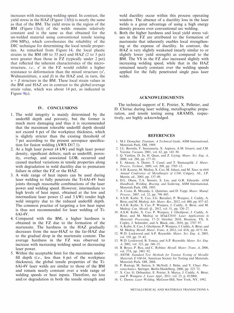
Figure 11 shows the representative profiles of thelocal tensile properties along the gauge length forweldments assembled at 160 J/mm. Compared to theBM, the yield stress is higher in the FZ but slightly lowerin the HAZ. This finding is consistent with the reportedresults on Ti-6Al-4V of a reduced strength for amicrostructure quenched from a temperature of1073 K (800 �C).[37] Figure 12 shows the strain distri-bution along the gauge length of the tensile sample justbefore rupture. For each strain distribution, the adjacentgradients in color (or shaded) indicate the relativeintensity. Hence, in these strain maps, the region of
strain concentration, indicated as the area with thehighest intensity, corresponds to the location of thefracture that occurred immediately afterward. Using theAramis strain distribution maps, the strain localizationjust prior to rupture can be methodically examined. Asindicated in Figures 11(b) and 12, the maximum localstrain is concentrated within the BM for all the weldsassembled at 2 and 3 kW. Hence despite the presence ofsome underfill and porosity defects, strain localization inthe FZ is minimal and may be attributed to the localstrengthening effect of the a¢ microstructure. Thus, it canbe concluded that the strengthening effect of the FZmicrostructure can compensate for the weakening effectof the welding defects, such as underfill and porosity, aslong as the size/amount of these remain below therecommended threshold/critical values.Figures 13 and 14 show the variation in the local
tensile properties as a function of the welding speed atlaser powers of 2 and 3 kW. It is apparent that the yieldstress values in the FZ are unequivocally higher thanthat of the BM and increase slightly with increasingwelding speed for the fully penetrated single pass welds.This is attributed to the finer prior-b grain structure and,in turn, more refined a¢ structure[38] associated with theincreased welding speed. Similarly, the maximum plasticstrain in the FZ, just before fracture (Figure 14(a)), also
Fig. 14—Maximum local plastic strain experienced in different regions of the welds assembled at 2 and 3 kW during tensile testing (the arrowidentifies the results obtained from a joint that was welded from both sides).
METALLURGICAL AND MATERIALS TRANSACTIONS A
increases with increasing welding speed. In contrast, theyield stress in the HAZ (Figure 13(b)) is nearly the sameas that of the BM. The yield stress in the region of theBM (Figure 13(c)) of the welds remains relativelyconstant and is the same as that obtained for theun-welded material using conventional tensile testing(996 MPa), which corroborates the reliability of theDIC technique for determining the local tensile proper-ties. As remarked from Figure 14, the local plasticstrains in the BM (40 to 55 pct) and HAZ (2 to 5 pct)were greater than those in FZ (typically under 2 pct)that reflected the inherent characteristics of the micro-structure, i.e., a¢ in the FZ would exhibit a higherresistance to deformation than the mixed structure (a¢,Widmanstatten, a and b) in the HAZ and, in turn, thea+ b structure in the BM. These local strain values inthe BM and HAZ are in contrast to the global/averagestrain value, which was about 14 pct, as indicated inFigure 9(c).
IV. CONCLUSIONS
1. The weld integrity is mainly determined by theunderfill depth and porosity, but the former ismuch more damaging and thus it is recommendedthat the maximum tolerable underfill depth shouldnot exceed 6 pct of the workpiece thickness, whichis slightly stricter than the existing threshold of7 pct according to the present aerospace specifica-tion for fusion welding (AWS D17.1).
2. At a high laser power (4 kW) and high laser powerdensity, significant defects, such as underfill, poros-ity, overlap, and associated LOB, occurred andcaused marked variations in tensile properties alongwith degradation in weld ductility due to prematurefailure in either the FZ or the HAZ.
3. A wide range of heat inputs can be used duringlaser welding to fully penetrate the Ti-6Al-4V buttjoints through reasonable combinations of the laserpower and welding speed. However, intermediate tohigh levels of heat input, obtained at the low andintermediate laser power (2 and 3 kW) render highweld integrity due to the reduced underfill depth.The common practice of targeting a low heat inputis thus not recommended for laser welding of Ti-6Al-4V.
4. Compared with the BM, a higher hardness isobtained in the FZ due to the formation of themartensite. The hardness in the HAZ graduallydecreases from the near-HAZ to the far-HAZ dueto the gradual drop in the martensite content. Theaverage hardness in the FZ was observed toincrease with increasing welding speed or decreasinglaser power.
5. Within the acceptable limit for the maximum under-fill depth (i.e., less than 6 pct of the workpiecethickness), the global tensile properties of the Ti-6Al-4V laser welds are similar to those of the BMand remain nearly constant over a wide range ofwelding speeds or heat inputs. Therefore, no lossand/or degradation in both the tensile strength and
weld ductility occur within this process operatingwindow. The absence of a ductility loss in the laserwelds is a great advantage of using a high energydensity process over conventional arc welding.
6. Both the higher hardness and local yield stress val-ues in the FZ are attributed to the formation ofmartensite that inherently enables local strengthen-ing at the expense of ductility. In contrast, theHAZ is very slightly weakened (nearly similar to orslightly lower yield strength) as compared to theBM. The YS in the FZ also increased slightly withincreasing welding speed, while that in the HAZremained nearly constant over the welding speedsapplied for the fully penetrated single pass laserwelds.
ACKNOWLEDGMENTS
The technical support of E. Poirier, X. Pelletier, andD. Chiriac during laser welding, metallographic prepa-ration, and tensile testing using ARAMIS, respec-tively, are highly acknowledged.
REFERENCES1. M.J. Donachie: Titanium: A Technical Guide, ASM International,
Materials Park, OH, 1989.2. J.L. Barreda, F. Santamarıa, X. Azpiroz, A.M. Irisarri, and J.M.
Varona: Vacuum, 2001, vol. 62, pp. 143–50.3. Q. Yunlian, D. Ju, H. Quan, and Z. Liying: Mater. Sci. Eng. A,
2000, vol. 280, pp. 177–81.4. E. Akman, A. Demir, T. Canel, and T. Sinmazcelik: J. Mater.
Process. Technol., 2009, vol. 209, pp. 3705–13.5. A.H. Kazzaz, M. Medraj, X. Cao, M. Jahazi, and M. Xiao: in 44th
Annual Conference of Metallurgist of CIM, Calgary, AL, J.P.Martin, ed., 2005, pp. 137–49.
6. D.L. Olson, T.A. Siewert, S. Liu, and G.R. Edwards: ASMHandbook, Welding, Brazing, and Soldering, ASM International,Materials Park, OH, 1993.
7. A. Costa, R. Miranda, L. Quintino, and D. Yapp: Mater. Manuf.Process., 2007, vol. 22, pp. 798–803.
8. A.S.H. Kabir, X. Cao, J.G. Baradari, P. Wanjara, J. Cuddy, A.Birur, andM.Medraj:Adv.Mater. Res., 2012, vol. 400, pp. 857–62.
9. A.S.H. Kabir, X. Cao, P. Wanjara, J. Cuddy, A. Birur, and M.Medraj: Can. Metall. Q., 2012, vol. 51, pp. 320–27.
10. A.S.H. Kabir, X. Cao, P. Wanjara, J. Gholipour, J. Cuddy, A.Birur, and M. Medraj: in MS&T2010: Laser Applications inMaterials Processing, 17–21 October 2010, Houston, TX, S.Copley, J. Schneider, and A. Black, eds., 2010, pp. 2787–97.
11. A.Kabir, X.Cao, J.Gholipour, P.Wanjara, J. Cuddy,A. Birur, andM. Medraj:Metall. Mater. Trans. A, 2012, vol. 43A, pp. 4171–84.
12. W.D. Lockwood and A.P. Reynolds: Mater. Sci. Eng. A, 2003,vol. 339, pp. 35–42.
13. W.D. Lockwood, B. Tomaz, and A.P. Reynolds: Mater. Sci. Eng.A, 2002, vol. 323, pp. 348–53.
14. B. Boyce, P. Reu, and C. Robino: Metall. Mater. Trans. A, 2006,vol. 37A, pp. 2481–92.
15. ASTM: Standard Test Methods for Tension Testing of MetallicMaterials E 8M-04, American Society for Testing and Materials,Materials Park, OH, 2004.
16. P. Rastogi, M. Sutton, S. McNeill, J. Helm, and Y. Chao: Pho-tomechanics, Springer, Berlin/Heidelberg, 2000, pp. 323–72.
17. X. Cao, G. Debaecker, E. Poirier, S. Marya, J. Cuddy, A. Birur,and P. Wanjara: J. Laser Appl., 2011, vol. 23, p. 012004.
18. C. Dawes: Laser Welding, McGraw-Hill, New York, NY, 1992.
METALLURGICAL AND MATERIALS TRANSACTIONS A
19. X. Cao, M. Jahazi, J.P. Immarigeon, and W. Wallace: J. Mater.Process. Technol., 2006, vol. 171, pp. 188–204.
20. Z. Khaled: J. Mater. Eng. Perform., 1994, vol. 3, pp. 419–34.21. D.R. Mitchell: Weld. J., 1982, vol. 61, pp. 157s–67s.22. F. Karimzadeh, M. Salehi, A. Saatchi, and M. Meratian: Mater.
Manuf. Process., 2005, vol. 20, pp. 205–19.23. G. Lutjering and J.C. Williams: Titanium, 2nd ed., Springer,
Berlin, 2007.24. M. Pastor, H. Zhao, and T. DebRoy: Rev. Metall., 2000, vol. 36,
pp. 108–17.25. T. Mohandas, D. Banerjee, and V. Kutumba Rao: Metall. Mater.
Trans. A, 1999, vol. 30A, pp. 789–98.26. A. Matsunawa, J.-D. Kim, N. Seto, M. Mizutani, and S.
Katayama: J. Laser Appl., 1998, vol. 10, pp. 247–54.27. AWS: Specification for Fusion Welding for Aerospace Application,
D17.1, American Welding Society, Miami, OH, 2001.28. M. Pastor, H. Zhao, R.P. Martukanitz, and T. DebRoy: Weld. J.,
1999, vol. 78, pp. 207s–16s.29. X. He, T. DebRoy, and P.W. Fuerschbach: J. Phys. D, 2003,
vol. 36, p. 3079.
30. X. He, J.T. Norris, P.W. Fuerschbach, and T. DebRoy: J. Phys. D,2006, vol. 39, p. 525.
31. X. Cao andM. Jahazi:Opt. Lasers Eng., 2009, vol. 47, pp. 1231–41.32. J. Weston, A. Jones, and R. Wallach: Proceedings of the 6th
International Conference on Welding and Melting by Electron andLaser Beams, Toulon, France, 1998, p. 187.
33. A.B. Short: Mater. Sci. Technol., 2009, vol. 25, pp. 309–24.34. T. Ahmed and H.J. Rack: Mater. Sci. Eng. A, 1998, vol. 243,
pp. 206–11.35. Z. Sun, D. Pan, and W. Zhang: Sixth International Conference on
Trends in Welding Research, Pine Mountain, Georgia, USA, 2002,pp. 760–67.
36. G.A. Knorovsky, P.W. Fuerschbach, S.E. Gianoulakis, and S.N.Burchett: in Trends in Welding Research: Proceedings of the 4thInternational Conference, 5–9 June 1995, Gatlinburg, TN, H.B.Smartt, J.A. Johnson, and S.A. David, eds., 1995, pp. 479–86.
37. Y. Lee, M. Peters, and G. Welsch: Metall. Trans. A, 1991,vol. 22A, pp. 709–14.
38. P. Wanjara, M. Brochu, and M. Jahazi: Mater. Manuf. Process.,2006, vol. 21, pp. 439–51.
METALLURGICAL AND MATERIALS TRANSACTIONS A