glasses, window system & mirrors i body gw aboredmder.com/fsms/nissan/murano/2003/gw.pdf ·...
TRANSCRIPT
GW-1
GLASSES, WINDOW SYSTEM & MIRRORS
I BODY
CONTENTS
C
D
E
F
G
H
J
K
L
M
SECTION GWA
B
GW
Revision; 2004 April 2003 Murano
GLASSES, WINDOW SYSTEM & MIRRORS
PRECAUTIONS .......................................................... 3Precautions for Supplemental Restraint System (SRS) “AIR BAG” and “SEAT BELT PRE-TEN-SIONER” .................................................................. 3Handling for Adhesive and Primer ........................... 3Wiring Diagrams and Trouble Diagnosis .................. 3
PREPARATION ........................................................... 4Special Service Tools ............................................... 4Commercial Service Tools ........................................ 4
SQUEAK AND RATTLE TROUBLE DIAGNOSES ..... 5Work Flow ................................................................ 5
CUSTOMER INTERVIEW ..................................... 5DUPLICATE THE NOISE AND TEST DRIVE ....... 6CHECK RELATED SERVICE BULLETINS ........... 6LOCATE THE NOISE AND IDENTIFY THE ROOT CAUSE ...................................................... 6REPAIR THE CAUSE ........................................... 6CONFIRM THE REPAIR ....................................... 7
Generic Squeak and Rattle Troubleshooting ........... 7INSTRUMENT PANEL .......................................... 7CENTER CONSOLE ............................................. 7DOORS ................................................................. 7TRUNK .................................................................. 8SUNROOF/HEADLINING ..................................... 8SEATS ................................................................... 8UNDERHOOD ....................................................... 8
Diagnostic Worksheet .............................................. 9WINDSHIELD GLASS ...............................................11
Removal and Installation .........................................11REMOVAL ............................................................11INSTALLATION ................................................... 12
BACK DOOR WINDOW GLASS .............................. 13Removal and Installation ........................................ 13
REMOVAL ........................................................... 13INSTALLATION ................................................... 14
SIDE WINDOW GLASS ............................................ 15Removal and Installation ........................................ 15
REMOVAL ........................................................... 15INSTALLATION ................................................... 16
POWER WINDOW SYSTEM .................................... 17
Component Parts and Harness Connector Location ... 17System Description ................................................. 18
MANUAL OPERATION ........................................ 18AUTO OPERATION ............................................. 20POWER WINDOW SERIAL LINK ....................... 20POWER WINDOW LOCK ................................... 20RETAINED POWER OPERATION ...................... 21ANTI-PINCH SYSTEM ........................................ 21POWER WINDOW CONTROL BY THE KEY CYLINDER SWITCH ........................................... 21
Schematic ............................................................... 22Wiring Diagram – WINDOW – ................................ 23Terminal and Reference Value for Power Window Main Switch ............................................................ 28Terminal and Reference Value for Front Power Win-dow Switch (Passenger Side) ................................. 29Terminal and Reference Value for BCM ................. 30Work Flow ............................................................... 30CONSULT-II Inspection Procedure ......................... 31
ACTIVE TEST ..................................................... 32WORK SUPPORT ............................................... 32DATA MONITOR ................................................. 32
Trouble Diagnosis Symptom Chart ......................... 33BCM Power Supply and Ground Circuit Check ...... 34Power Window Main Switch Power Supply Circuit Check ..................................................................... 35Front Power Window Switch (Passenger Side) Power Supply and Ground Circuit Check ............... 36Front Power Window Regulator (Driver Side) Circuit Check ..................................................................... 37Front Power Window Regulator (Passenger Side) Circuit Check .......................................................... 38Rear Power Window Regulator (LH) Circuit Check ... 39Rear Power Window Regulator (RH) Circuit Check ... 41Limit Switch Circuit Check (Driver Side) ................. 43Limit Switch Circuit Check (Passenger Side) ......... 44Encoder Circuit Check (Driver Side) ....................... 46Encoder Circuit Check (Front Passenger Side) ...... 48Door Switch Check ................................................. 51Front Door Key Cylinder Switch (Driver Side) Check ... 53
GW-2Revision; 2004 April 2003 Murano
Power Window Serial Link Check ........................... 55Power Window Lock Switch Check ........................ 57
FRONT DOOR GLASS AND REGULATOR ............. 58Removal and Installation ........................................ 58
REMOVAL ........................................................... 58INSTALLATION .................................................... 59INSPECTION AFTER REMOVAL ........................ 59DISASSEMBLY AND ASSEMBLY ....................... 59SETTING AFTER INSTALLATION ...................... 60FITTING INSPECTION ........................................ 60
REAR DOOR GLASS AND REGULATOR ............... 61Removal and Installation ........................................ 61
REMOVAL ........................................................... 61INSTALLATION .................................................... 62INSPECTION AFTER REMOVAL ........................ 62FITTING INSPECTION ........................................ 62
INSIDE MIRROR ....................................................... 63Wiring Diagram –I/MIRR– ....................................... 63Removal and Installation ........................................ 64
REMOVAL ........................................................... 64INSTALLATION .................................................... 64
REAR WINDOW DEFOGGER .................................. 65Component Parts and Harness Connector Location ... 65System Description ................................................. 65CAN Communication System Description .............. 67CAN Communication Unit For 2WD Models ........... 67
TYPE 1/TYPE 2/TYPE 3/TYPE 4/TYPE 5/TYPE 6/TYPE 7/TYPE 8 ................................................ 68TYPE 9/TYPE10/TYPE 11/TYPE 12/TYPE 13/TYPE 14/TYPE 15/TYPE 16 ............................... 73
CAN Communication Unit For AWD Models .......... 78TYPE 17/TYPE 18/TYPE 19/TYPE 20/TYPE 21/TYPE 22/TYPE 23/TYPE 24 ............................... 78TYPE 25/TYPE26/TYPE 27/TYPE 28/TYPE 29/
TYPE 30/TYPE 31/TYPE 32 ................................84Schematic – DEF – .................................................89Wiring Diagram –DEF– ...........................................90Terminal and Reference Value for BCM ..................94Terminal and Reference Value for IPDM E/R ..........94Work Flow ...............................................................94CONSULT-II Inspection Procedure .........................95
DATA MONITOR ..................................................96ACTIVE TEST ......................................................96
Trouble Diagnoses Symptom Chart ........................97BCM Power Supply and Ground Circuit Check ......98Rear Window Defogger Switch Circuit Check .........99Rear Window Defogger Power Supply Circuit Check ....................................................................100Rear Window Defogger Circuit Check ..................102Door Mirror Defogger Power Supply Circuit Check .103Driver Side Door Mirror Defogger Circuit Check ...105Passenger Side Door Mirror Defogger Circuit Check
.106Rear Window Defogger Signal Check ..................107Filament Check .....................................................108Filament Repair .....................................................108
REPAIR EQUIPMENT .......................................108REPAIRING PROCEDURE ...............................109
DOOR MIRROR .......................................................110Automatic Drive Positioner Interlocking Door Mirror . 110Power Door Mirror (Only Manual Operation Model) . 111
WIRING DIAGRAM –MIRROR– ........................ 111Removal and Installation ....................................... 112
REMOVAL .......................................................... 112INSTALLATION .................................................. 112
Disassembly and Assembly .................................. 112DISASSEMBLY .................................................. 112ASSEMBLY ........................................................ 113

PRECAUTIONS
GW-3
C
D
E
F
G
H
J
K
L
M
A
B
GW
Revision; 2004 April 2003 Murano
PRECAUTIONS PFP:00001
Precautions for Supplemental Restraint System (SRS) “AIR BAG” and “SEAT BELT PRE-TENSIONER” AIS001RL
The Supplemental Restraint System such as “AIR BAG” and “SEAT BELT PRE-TENSIONER”, used alongwith a front seat belt, helps to reduce the risk or severity of injury to the driver and front passenger for certaintypes of collision. This system includes seat belt switch inputs and dual stage front air bag modules. The SRSsystem uses the seat belt switches to determine the front air bag deployment, and may only deploy one frontair bag, depending on the severity of a collision and whether the front occupants are belted or unbelted.Information necessary to service the system safely is included in the SRS and SB section of this Service Man-ual.WARNING:● To avoid rendering the SRS inoperative, which could increase the risk of personal injury or death
in the event of a collision which would result in air bag inflation, all maintenance must be per-formed by an authorized NISSAN/INFINITI dealer.
● Improper maintenance, including incorrect removal and installation of the SRS, can lead to per-sonal injury caused by unintentional activation of the system. For removal of Spiral Cable and AirBag Module, see the SRS section.
● Do not use electrical test equipment on any circuit related to the SRS unless instructed to in thisService Manual. SRS wiring harnesses can be identified by yellow and/or orange harnesses orharness connectors.
Handling for Adhesive and Primer AIS001RM
● Do not use an adhesive which is past its usable date. Shelf life of this product is limited to six months afterthe date of manufacture. Carefully adhere to the expiration or manufacture date printed on the box.
● Keep primers and adhesive in a cool, dry place. Ideally, they should be stored in a refrigerator.● Open the seal of the primer and adhesive just before application. Discard the remainder.● Before application, be sure to shake the primer container to stir the contents. If any floating material is
found, do not use it.● If any primer or adhesive contacts the skin, wipe it off with gasoline or equivalent and wash the skin with
soap.● When using primer and adhesive, always observe the precautions in the instruction manual.
Wiring Diagrams and Trouble Diagnosis AIS001RN
When you read wiring diagrams, refer to the following:● GI-14, "How to Read Wiring Diagrams"● PG-3, "POWER SUPPLY ROUTING CIRCUIT"When you perform trouble diagnosis, refer to the following:● GI-10, "HOW TO FOLLOW TEST GROUPS IN TROUBLE DIAGNOSES"● GI-26, "How to Perform Efficient Diagnosis for an Electrical Incident"Check for any service bulletins before servicing the vehicle.

GW-4
PREPARATION
Revision; 2004 April 2003 Murano
PREPARATION PFP:00002
Special Service Tools AIS005AD
The actual shapes of Kent-Moore tools may differ from those of special service tools illustrated here.
Commercial Service Tools AIS005AE
Tool number(Kent-Moore No.)Tool name
Description
(J39570)Chassis ear
Locating the noise
(J43980)NISSAN Squeak and Rattle Kit
Repairing the cause of noise
SIIA0993E
SIIA0994E
Tool name Description
Engine ear Locating the noise
SIIA0995E

SQUEAK AND RATTLE TROUBLE DIAGNOSES
GW-5
C
D
E
F
G
H
J
K
L
M
A
B
GW
Revision; 2004 April 2003 Murano
SQUEAK AND RATTLE TROUBLE DIAGNOSES PFP:00000
Work Flow AIS005AF
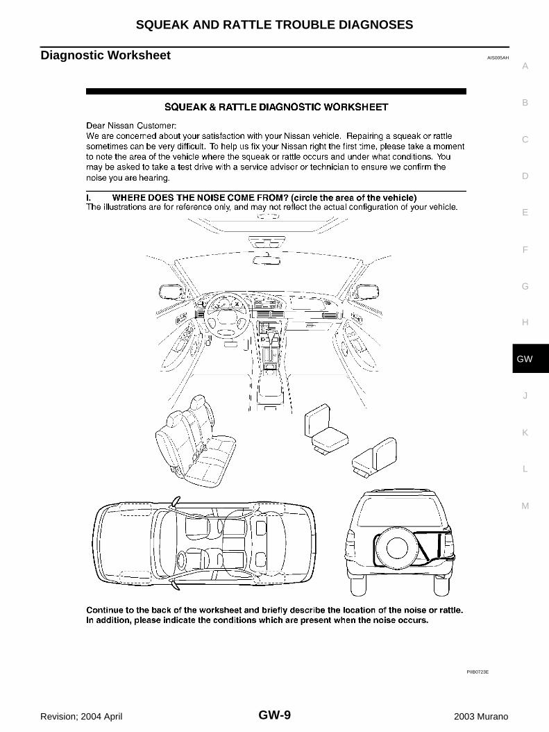
CUSTOMER INTERVIEWInterview the customer if possible, to determine the conditions that exist when the noise occurs. Use the Diag-nostic Worksheet during the interview to document the facts and conditions when the noise occurs and anycustomer's comments; refer to GW-9, "Diagnostic Worksheet" . This information is necessary to duplicate theconditions that exist when the noise occurs.● The customer may not be able to provide a detailed description or the location of the noise. Attempt to
obtain all the facts and conditions that exist when the noise occurs (or does not occur).● If there is more than one noise in the vehicle, be sure to diagnose and repair the noise that the customer
is concerned about. This can be accomplished by test driving the vehicle with the customer.● After identifying the type of noise, isolate the noise in terms of its characteristics. The noise characteristics
are provided so the customer, service adviser and technician are all speaking the same language whendefining the noise.
● Squeak —(Like tennis shoes on a clean floor)Squeak characteristics include the light contact/fast movement/brought on by road conditions/hard sur-faces=higher pitch noise/softer surfaces=lower pitch noises/edge to surface=chirping
● Creak—(Like walking on an old wooden floor)Creak characteristics include firm contact/slow movement/twisting with a rotational movement/pitchdependent on materials/often brought on by activity.
● Rattle—(Like shaking a baby rattle)Rattle characteristics include the fast repeated contact/vibration or similar movement/loose parts/missingclip or fastener/incorrect clearance.
● Knock —(Like a knock on a door)Knock characteristics include hollow sounding/sometimes repeating/often brought on by driver action.
● Tick—(Like a clock second hand)Tick characteristics include gentle contacting of light materials/loose components/can be caused by driveraction or road conditions.
● Thump—(Heavy, muffled knock noise)Thump characteristics include softer knock/dead sound often brought on by activity.
● Buzz—(Like a bumble bee)Buzz characteristics include high frequency rattle/firm contact.
● Often the degree of acceptable noise level will vary depending upon the person. A noise that you mayjudge as acceptable may be very irritating to the customer.
● Weather conditions, especially humidity and temperature, may have a great effect on noise level.
SBT842

GW-6
SQUEAK AND RATTLE TROUBLE DIAGNOSES
Revision; 2004 April 2003 Murano
DUPLICATE THE NOISE AND TEST DRIVEIf possible, drive the vehicle with the customer until the noise is duplicated. Note any additional information onthe Diagnostic Worksheet regarding the conditions or location of the noise. This information can be used toduplicate the same conditions when you confirm the repair.If the noise can be duplicated easily during the test drive, to help identify the source of the noise, try to dupli-cate the noise with the vehicle stopped by doing one or all of the following:1) Close a door.2) Tap or push/pull around the area where the noise appears to be coming from.3) Rev the engine.4) Use a floor jack to recreate vehicle “twist”.5) At idle, apply engine load (electrical load, half-clutch on M/T models, drive position on A/T models).6) Raise the vehicle on a hoist and hit a tire with a rubber hammer.● Drive the vehicle and attempt to duplicate the conditions the customer states exist when the noise occurs.● If it is difficult to duplicate the noise, drive the vehicle slowly on an undulating or rough road to stress the
vehicle body.
CHECK RELATED SERVICE BULLETINSAfter verifying the customer concern or symptom, check ASIST for Technical Service Bulletins (TSBs) relatedto that concern or symptom.If a TSB relates to the symptom, follow the procedure to repair the noise.
LOCATE THE NOISE AND IDENTIFY THE ROOT CAUSE1. Narrow down the noise to a general area. To help pinpoint the source of the noise, use a listening tool
(Chassis Ear: J39570, Engine Ear and mechanics stethoscope).2. Narrow down the noise to a more specific area and identify the cause of the noise by:● removing the components in the area that you suspect the noise is coming from.
Do not use too much force when removing clips and fasteners, otherwise clips and fastener can be brokenor lost during the repair, resulting in the creation of new noise.
● tapping or pushing/pulling the component that you suspect is causing the noise.Do not tap or push/pull the component with excessive force, otherwise the noise will be eliminated onlytemporarily.
● feeling for a vibration with your hand by touching the component(s) that you suspect is (are) causing thenoise.
● placing a piece of paper between components that you suspect are causing the noise.● looking for loose components and contact marks.
Refer to GW-7, "Generic Squeak and Rattle Troubleshooting" .
REPAIR THE CAUSE● If the cause is a loose component, tighten the component securely.● If the cause is insufficient clearance between components:– separate components by repositioning or loosening and retightening the component, if possible.– insulate components with a suitable insulator such as urethane pads, foam blocks, felt cloth tape or ure-
thane tape. A Nissan Squeak and Rattle Kit (J43980) is available through your authorized Nissan PartsDepartment.
CAUTION:Do not use excessive force as many components are constructed of plastic and may be damaged.Always check with the Parts Department for the latest parts information.The following materials are contained in the Nissan Squeak and Rattle Kit (J43980). Each item can beordered separately as needed.URETHANE PADS [1.5 mm (0.059 in) thick]Insulates connectors, harness, etc.76268-9E005: 100 × 135 mm (3.94 × 5.31 in)/76884-71L01: 60 × 85 mm (2.36 × 3.35 in)/76884-71L02: 15 × 25 mm (0.59 × 0.98 in)INSULATOR (Foam blocks)Insulates components from contact. Can be used to fill space behind a panel.73982-9E000: 45 mm (1.77 in) thick, 50 × 50 mm (1.97 × 1.97 in)/73982-50Y00: 10 mm (0.39 in) thick, 50 × 50 mm (1.97 × 1.97 in)

SQUEAK AND RATTLE TROUBLE DIAGNOSES
GW-7
C
D
E
F
G
H
J
K
L
M
A
B
GW
Revision; 2004 April 2003 Murano
INSULATOR (Light foam block)80845-71L00: 30 mm (1.18 in) thick, 30 × 50 mm (1.18 × 1.97 in)FELT CLOTHTAPEUsed to insulate where movement does not occur. Ideal for instrument panel applications.68370-4B000: 15 × 25 mm (0.59 × 0.98 in) pad/68239-13E00: 5 mm (0.20 in) wide tape roll. The fol-lowing materials, not found in the kit, can also be used to repair squeaks and rattles.UHMW (TEFLON) TAPEInsulates where slight movement is present. Ideal for instrument panel applications.SILICONE GREASEUsed in place of UHMW tape that will be visible or not fit.Note: Will only last a few months.SILICONE SPRAYUse when grease cannot be applied.DUCT TAPEUse to eliminate movement.
CONFIRM THE REPAIRConfirm that the cause of a noise is repaired by test driving the vehicle. Operate the vehicle under the sameconditions as when the noise originally occurred. Refer to the notes on the Diagnostic Worksheet.
Generic Squeak and Rattle Troubleshooting AIS005AG
Refer to Table of Contents for specific component removal and installation information.
INSTRUMENT PANELMost incidents are caused by contact and movement between:1. The cluster lid A and instrument panel2. Acrylic lens and combination meter housing3. Instrument panel to front pillar garnish4. Instrument panel to windshield5. Instrument panel mounting pins6. Wiring harnesses behind the combination meter7. A/C defroster duct and duct jointThese incidents can usually be located by tapping or moving the components to duplicate the noise or bypressing on the components while driving to stop the noise. Most of these incidents can be repaired by apply-ing felt cloth tape or silicon spray (in hard to reach areas). Urethane pads can be used to insulate wiring har-ness.CAUTION:Do not use silicone spray to isolate a squeak or rattle. If you saturate the area with silicone, you willnot be able to recheck the repair.
CENTER CONSOLEComponents to pay attention to include:1. Shifter assembly cover to finisher2. A/C control unit and cluster lid C3. Wiring harnesses behind audio and A/C control unitThe instrument panel repair and isolation procedures also apply to the center console.
DOORSPay attention to the:1. Finisher and inner panel making a slapping noise2. Inside handle escutcheon to door finisher3. Wiring harnesses tapping4. Door striker out of alignment causing a popping noise on starts and stopsTapping or moving the components or pressing on them while driving to duplicate the conditions can isolatemany of these incidents. You can usually insulate the areas with felt cloth tape or insulator foam blocks fromthe Nissan Squeak and Rattle Kit (J43980) to repair the noise.

GW-8
SQUEAK AND RATTLE TROUBLE DIAGNOSES
Revision; 2004 April 2003 Murano
TRUNKTrunk noises are often caused by a loose jack or loose items put into the trunk by the owner.In addition look for:1. Trunk lid dumpers out of adjustment2. Trunk lid striker out of adjustment3. The trunk lid torsion bars knocking together4. A loose license plate or bracketMost of these incidents can be repaired by adjusting, securing or insulating the item(s) or component(s) caus-ing the noise.
SUNROOF/HEADLININGNoises in the sunroof/headlining area can often be traced to one of the following:1. Sunroof lid, rail, linkage or seals making a rattle or light knocking noise2. Sunvisor shaft shaking in the holder3. Front or rear windshield touching headlining and squeakingAgain, pressing on the components to stop the noise while duplicating the conditions can isolate most of theseincidents. Repairs usually consist of insulating with felt cloth tape.
SEATSWhen isolating seat noise it's important to note the position the seat is in and the load placed on the seat whenthe noise is present. These conditions should be duplicated when verifying and isolating the cause of thenoise.Cause of seat noise include:1. Headrest rods and holder2. A squeak between the seat pad cushion and frame3. The rear seatback lock and bracketThese noises can be isolated by moving or pressing on the suspected components while duplicating the con-ditions under which the noise occurs. Most of these incidents can be repaired by repositioning the componentor applying urethane tape to the contact area.
UNDERHOODSome interior noise may be caused by components under the hood or on the engine wall. The noise is thentransmitted into the passenger compartment.Causes of transmitted underhood noise include:1. Any component mounted to the engine wall2. Components that pass through the engine wall3. Engine wall mounts and connectors4. Loose radiator mounting pins5. Hood bumpers out of adjustment6. Hood striker out of adjustmentThese noises can be difficult to isolate since they cannot be reached from the interior of the vehicle. The bestmethod is to secure, move or insulate one component at a time and test drive the vehicle. Also, engine RPMor load can be changed to isolate the noise. Repairs can usually be made by moving, adjusting, securing, orinsulating the component causing the noise.
SQUEAK AND RATTLE TROUBLE DIAGNOSES
GW-9
C
D
E
F
G
H
J
K
L
M
A
B
GW
Revision; 2004 April 2003 Murano
Diagnostic Worksheet AIS005AH
PIIB0723E

GW-10
SQUEAK AND RATTLE TROUBLE DIAGNOSES
Revision; 2004 April 2003 Murano
SBT844

WINDSHIELD GLASS
GW-11
C
D
E
F
G
H
J
K
L
M
A
B
GW
Revision; 2004 April 2003 Murano
WINDSHIELD GLASS PFP:72712
Removal and Installation AIS005AI
REMOVAL1. Remove the front pillar garnish. Refer to EI-32, "BODY SIDE TRIM" .2. Partially remove the headlining (front edge). Refer to EI-36, "HEADLINING" .3. Remove the front wiper arms. Refer to WW-47, "Removal and Installation of Front Wiper Arms, Adjust-
ment of Wiper Arms Stop Location" .4. Remove roof side molding. Refer to EI-28, "ROOF SIDE MOLDING" .5. Apply a protective tape around the windshield glass to protect the painted surface from damage.After removing moldings, remove glass using piano wire or power cutting tool and an inflatable pump bag.● If a windshield glass is to be reused, mark the body and the glass with mating marks.
PIIA3784E
1. Clip (C103) 2. Fastener 3. Molding
4. Windshield glass 5. Spacer 6. Mirror base
7. Bond 8. Insulator 9. Panel
10. Body side (outer) 11. Cowl top cover

GW-12
WINDSHIELD GLASS
Revision; 2004 April 2003 Murano
WARNING:When cutting the glass from the vehicle, always wear safety glasses and heavy gloves to help preventglass splinters from entering your eyes or cutting your hands.CAUTION:● When a windshield glass is to be reused, do not use a cutting knife or power cutting tool.● Be careful not to scratch the glass when removing.● Do not set or stand the glass on its edge. Small chips may develop into cracks.
INSTALLATION● Use a genuine Nissan Urethane Adhesive Kit or equivalent and follow the instructions furnished with it.● While the urethane adhesive is curing, open a door window. This will prevent the glass from being forced
out by passenger room air pressure when a door is closed.● The molding must be installed securely so that it is in position and leaves no gap.● Inform the customer that the vehicle should remain stationary until the urethane adhesive has completely
cured (preferably 24 hours). Curing time varies with temperature and humidity.WARNING:● Keep heat and open flames away as primers and adhesive are flammable.● The materials contained in the kit are harmful if swallowed, and may irritate skin and eyes. Avoid
contact with the skin and eyes.● Use in an open, well ventilated location. Avoid breathing the vapors. They can be harmful if
inhaled. If affected by vapor inhalation, immediately move to an area with fresh air.● Driving the vehicle before the urethane adhesive has completely cured may affect the perfor-
mance of the windshield in case of an accident.CAUTION:● Do not use an adhesive which is past its usable term. Shelf life of this product is limited to six
months after the date of manufacture. Carefully adhere to the expiration or manufacture dateprinted on the box.
● Keep primers and adhesive in a cool, dry place. Ideally, they should be stored in a refrigerator.● Do not leave primers or adhesive cartridge unattended with their caps open or off.● The vehicle should not be driven for at least 24 hours or until the urethane adhesive has com-
pletely cured. Curing time varies depending on temperature and humidity. The curing time willincrease under lower temperature and lower humidity.
Repairing Water Leaks for WindshieldLeaks can be repaired without removing and reinstalling glass.If water is leaking between the urethane adhesive material and body or glass, determine the extent of leakage.This can be done by applying water to the windshield area while pushing glass outward.To stop the leak, apply primer (if necessary) and then urethane adhesive to the leak point.
PIIA0186E

BACK DOOR WINDOW GLASS
GW-13
C
D
E
F
G
H
J
K
L
M
A
B
GW
Revision; 2004 April 2003 Murano
BACK DOOR WINDOW GLASS PFP:90300
Removal and Installation AIS005AJ
REMOVAL1. Remove the back door finisher. Refer to EI-40, "BACK DOOR TRIM" .2. Remove the rear wiper arm. Refer to WW-65, "Removal and Installation of Rear Wiper Arm, Adjustment of
Wiper Arms Stop Location" .3. Remove the connectors and grounds for the rear window defogger and printed antenna.4. Remove glass using cutting knife or power cutting tool and an inflatable pump bag.● If a back door window glass is to be reused, mark the body and the glass with mating marks.WARNING:When cutting the glass from the vehicle, always wear safety glasses and heavy gloves to help preventglass splinters from entering your eyes or cutting your hands.CAUTION:● Be careful not to scratch the glass when removing.
1. Dam rubber 2. Back door window glass 3. Bond
4. Back door outer panel
PIIA3785E

GW-14
BACK DOOR WINDOW GLASS
Revision; 2004 April 2003 Murano
● Do not set or stand the glass on its edge. Small chips may develop into cracks.
INSTALLATION● Use a genuine Nissan Urethane Adhesive Kit or equivalent and follow the instructions furnished with it.● While the urethane adhesive is curing, open a door window. This will prevent the glass from being forced
out by passenger room air pressure when a door is closed.● Inform the customer that the vehicle should remain stationary until the urethane adhesive has completely
cured (preferably 24 hours). Curing time varies with temperature and humidity.WARNING:● Keep heat and open flames away as primers and adhesive are flammable.● The materials contained in the kit are harmful if swallowed, and may irritate skin and eyes. Avoid
contact with the skin and eyes.● Use in an open, well ventilated location. Avoid breathing the vapors. They can be harmful if
inhaled. If affected by vapor inhalation, immediately move to an area with fresh air.● Driving the vehicle before the urethane adhesive has completely cured may affect the perfor-
mance of the back door window glass in case of an accident.CAUTION:● Do not use an adhesive which is past its usable term. Shelf life of this product is limited to six
months after the date of manufacture. Carefully adhere to the expiration or manufacture dateprinted on the box.
● Keep primers and adhesive in a cool, dry place. Ideally, they should be stored in a refrigerator.● Do not leave primers or adhesive cartridge unattended with their caps open or off.● The vehicle should not be driven for at least 24 hours or until the urethane adhesive has com-
pletely cured. Curing time varies depending on temperature and humidity. The curing time willincrease under lower temperature and lower humidity.
PIIB0908E
SIDE WINDOW GLASS
GW-15
C
D
E
F
G
H
J
K
L
M
A
B
GW
Revision; 2004 April 2003 Murano
SIDE WINDOW GLASS PFP:83300
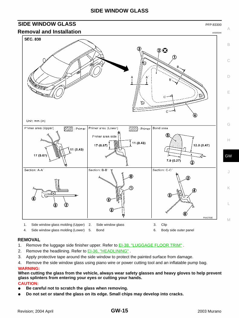
Removal and Installation AIS005AK
REMOVAL1. Remove the luggage side finisher upper. Refer to EI-38, "LUGGAGE FLOOR TRIM" .2. Remove the headlining. Refer to EI-36, "HEADLINING" .3. Apply protective tape around the side window to protect the painted surface from damage.4. Remove the side window glass using piano wire or power cutting tool and an inflatable pump bag.WARNING:When cutting the glass from the vehicle, always wear safety glasses and heavy gloves to help preventglass splinters from entering your eyes or cutting your hands.CAUTION:● Be careful not to scratch the glass when removing.● Do not set or stand the glass on its edge. Small chips may develop into cracks.
PIIA3793E
1. Side window glass molding (Upper) 2. Side window glass 3. Clip
4. Side window glass molding (Lower) 5. Bond 6. Body side outer panel
GW-16
SIDE WINDOW GLASS
Revision; 2004 April 2003 Murano
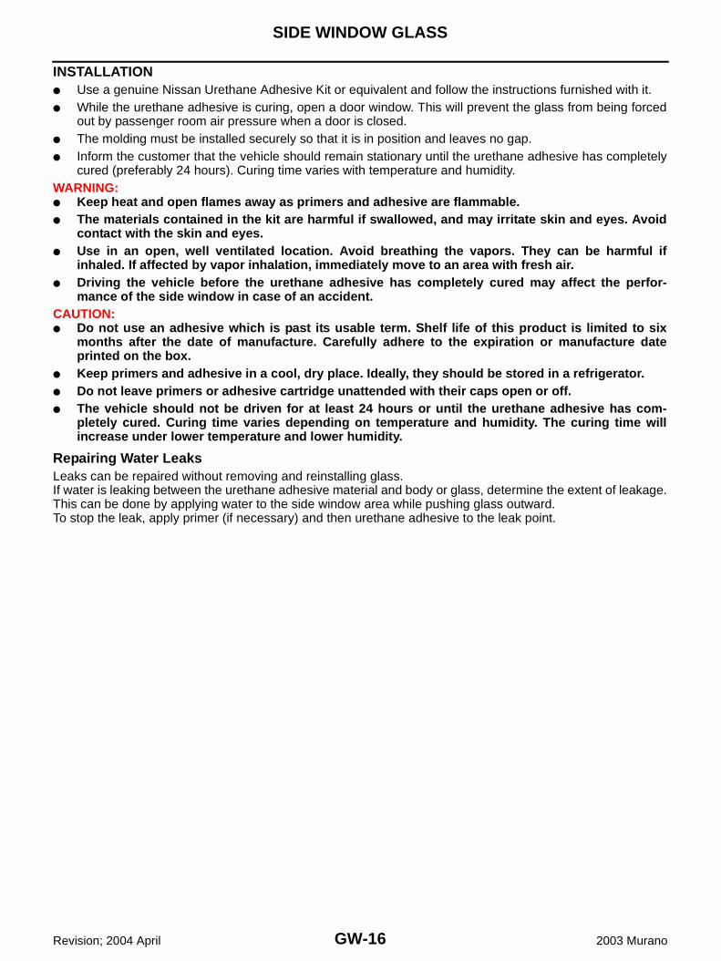
INSTALLATION● Use a genuine Nissan Urethane Adhesive Kit or equivalent and follow the instructions furnished with it.● While the urethane adhesive is curing, open a door window. This will prevent the glass from being forced
out by passenger room air pressure when a door is closed.● The molding must be installed securely so that it is in position and leaves no gap.● Inform the customer that the vehicle should remain stationary until the urethane adhesive has completely
cured (preferably 24 hours). Curing time varies with temperature and humidity.WARNING:● Keep heat and open flames away as primers and adhesive are flammable.● The materials contained in the kit are harmful if swallowed, and may irritate skin and eyes. Avoid
contact with the skin and eyes.● Use in an open, well ventilated location. Avoid breathing the vapors. They can be harmful if
inhaled. If affected by vapor inhalation, immediately move to an area with fresh air.● Driving the vehicle before the urethane adhesive has completely cured may affect the perfor-
mance of the side window in case of an accident.CAUTION:● Do not use an adhesive which is past its usable term. Shelf life of this product is limited to six
months after the date of manufacture. Carefully adhere to the expiration or manufacture dateprinted on the box.
● Keep primers and adhesive in a cool, dry place. Ideally, they should be stored in a refrigerator.● Do not leave primers or adhesive cartridge unattended with their caps open or off.● The vehicle should not be driven for at least 24 hours or until the urethane adhesive has com-
pletely cured. Curing time varies depending on temperature and humidity. The curing time willincrease under lower temperature and lower humidity.
Repairing Water LeaksLeaks can be repaired without removing and reinstalling glass.If water is leaking between the urethane adhesive material and body or glass, determine the extent of leakage.This can be done by applying water to the side window area while pushing glass outward.To stop the leak, apply primer (if necessary) and then urethane adhesive to the leak point.
POWER WINDOW SYSTEM
GW-17
C
D
E
F
G
H
J
K
L
M
A
B
GW
Revision; 2004 April 2003 Murano
POWER WINDOW SYSTEM PFP:25401
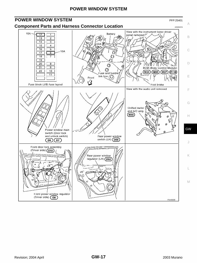
Component Parts and Harness Connector Location AIS002CN
PIIA4683E
GW-18
POWER WINDOW SYSTEM
Revision; 2004 April 2003 Murano
System Description AIS002CO
Power is supplied at all time● from 50A fusible link (letter F , located in the fuse and fusible link box)● to BCM terminal 7● through BCM terminal 28● to power window main switch terminal 19● to front power window switch (passenger side) terminal 10.With ignition switch in ON or START position, Power is supplied● through 10A fuse [No.1,located in the fuse block (J/B)]● to BCM terminal 35● through BCM terminal 29● to power window main switch terminal 10● to rear power window switch (LH and RH) terminal 1.Ground supplied ● to BCM terminal 8● through body grounds E13, E26 and E28● to power window main switch terminal 17● through body grounds M14 and M78● to front power window switch (passenger side) terminal 11● through body grounds M14 and M78
MANUAL OPERATIONFront Driver Side Door WINDOW UPWhen the front driver side switch in the power window main switch is pressed in the up position, Power is supplied● to front power window regulator (driver side) terminal 2● through power window main switch terminal 8.Ground is supplied● to front power window regulator (driver side) terminal 1● through power window main switch terminal 11.Then, the motor raises the window until the switch is released.WINDOW DOWNWhen the front driver side switch in the power window main switch is pressed in the down positionPower is supplied● to front power window regulator (driver side) terminal 1● through power window main switch terminal 11.Ground is supplied● to front power window regulator (driver side) terminal 2● through power window main switch terminal 8.Then, the motor lowers the window until the switch is released.

POWER WINDOW SYSTEM
GW-19
C
D
E
F
G
H
J
K
L
M
A
B
GW
Revision; 2004 April 2003 Murano
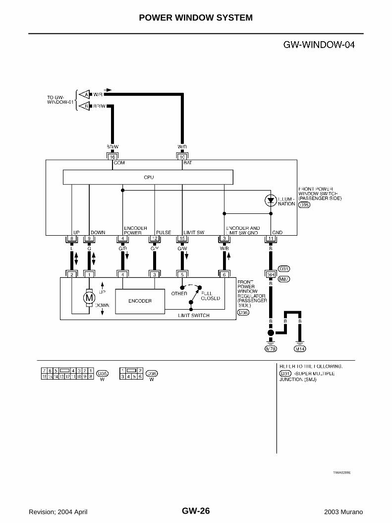
Front Passenger Side Door FRONT POWER WINDOW SWITCH (PASSENGER SIDE) OPERATIONGround is supplied● to front power window switch (passenger side) terminal 11● through body grounds M14 and M78.WINDOW UPWhen the front power window switch (passenger side) is pressed in the up positionPower is supplied● to front power window regulator (passenger side) terminal 2● through front power window switch (passenger side) terminal 8.Ground is supplied● to front power window regulator (passenger side) terminal 1● through front power window switch (passenger side) terminal 9.Then, the motor raises the window until the switch is released.WINDOW DOWN When the front power window switch (passenger side) is pressed in the down positionPower is supplied● to front power window regulator (passenger side) terminal 1● through front power window switch (passenger side) terminal 9.Ground is supplied● to front power window regulator (passenger side) terminal 2● through front power window switch (passenger side) terminal 8.Then, the motor lowers the window until the switch is released.POWER WINDOW MAIN SWITCH OPERATIONSignal is sent● to front power window switch (passenger side) terminal 16● though power window main switch terminal 14.The operation of power window after receive the signal is as same as operate the power window with sub-switch (front passenger side).
Rear Door (LH or RH)REAR POWER WINDOW SWITCH (LH OR RH) OPERATIONWINDOW UPWhen the rear power window switch (LH or RH) is pressed in the up positionPower is supplied● to rear power window regulator (LH or RH) terminal 2● through rear power window switch (LH or RH) terminal 5.Ground is supplied● to rear power window regulator (LH or RH) terminal 1● through rear power window switch (LH or RH) terminal 4.Then, the motor raises the window until the switch is released.WINDOW DOWNWhen the rear power window switch (LH or RH) is pressed in the down positionPower is supplied● to rear power window regulator (LH or RH) terminal 1● through rear power window switch (LH or RH) terminal 4.Ground is supplied● to rear power window regulator (LH or RH) terminal 2● through rear power window switch (LH or RH) terminal 5.Then, the motor lowers the window until the switch is released.

GW-20
POWER WINDOW SYSTEM
Revision; 2004 April 2003 Murano
POWER WINDOW MAIN SWITCH OPERATIONWINDOW UPWhen the power window main switch (rear LH or RH) is pressed in the up positionPower is supplied● to rear power window switch (LH or RH) terminal 2● through power window main switch terminal 1 (LH) or 7 (RH)● to rear power window regulator (LH or RH) terminal 2● through rear power window switch (LH or RH) terminal 5.Ground is supplied● to rear power window regulator (LH or RH) terminal 1● through rear power window switch (LH or RH) terminal 4● to power window main switch terminal 3 (RH) or 5 (LH)● through rear power window switch (LH or RH) terminal 3.Then, the motor raises the window until the switch is released.WINDOW DOWNWhen the power window main switch (rear LH or RH) is pressed in the down positionPower is supplied● to rear power window switch (LH or RH) terminal 3● through power window main switch terminal 3 (LH) or 5 (RH)● to rear power window regulator (LH or RH) terminal 1● through rear power window switch (LH or RH) terminal 4.Ground is supplied● to rear power window regulator (LH or RH) terminal 2● through rear power window switch (LH or RH) terminal 5● to power window main switch terminal 1 (LH) or 7 (RH)● through rear power window switch (LH or RH) terminal 2Then, the motor raises the window until the switch is released.
AUTO OPERATIONThe power window AUTO feature enables the driver to open or close the window without holding the windowswitch in the down or up position.
POWER WINDOW SERIAL LINKPower window main switch, front power window switch (passenger side) and BCM transmit and receive thesignal by power window serial link.The under mentioned signal is transmitted from power window main switch to front power window switch (pas-senger side)● Front passenger side door window operation signal.● Power window control by key cylinder switch signal.● Power window lock switch signal.
POWER WINDOW LOCKThe power window lock is designed to lock operation of all windows except for driver side door window.When the lock position, ground of the rear power window switches in the power window main switch is discon-nected. This prevents the power window motors from operating.

POWER WINDOW SYSTEM
GW-21
C
D
E
F
G
H
J
K
L
M
A
B
GW
Revision; 2004 April 2003 Murano
RETAINED POWER OPERATIONWhen the ignition switch is turned to the OFF position from ON or START position.Power is supplied for 45 seconds ● to power window main switch terminal 10.● to rear power window switch (LH and RH) terminals 1● from BCM terminal 29.Then the power window can be operated.When power and ground are supplied, the BCM continues to be energized, and the power window can beoperated.The retained power operation is canceled when the driver or passenger side door is opened.RAP signal period can be changed by CONSULT-II. Refer to GW-31, "CONSULT-II Inspection Procedure" .
ANTI-PINCH SYSTEMPower window main switch and front power window switch (passenger side) monitors the power window regu-lator motor operation and the power window position (full closed or other) for driver side and passenger sidepower window by the signals from encoder and limit switch in front power window regulator (driver side andpassenger side).When power window main switch detects interruption during the following close operation,● automatic close operation when ignition switch is in the “ON” position● automatic close operation during retained power operation● manual close operation during retained power operationPower window main switch or power window sub-switch (passenger side) controls each power window regula-tor motor for open and the power window will be lowered about 150 mm (5.91 in).
POWER WINDOW CONTROL BY THE KEY CYLINDER SWITCHWhen ignition key switch is OFF, front power window can be opened or closed by turning the front door keycylinder driver side UNLOCK / LOCK position more then 1.5 second over condition.● Power window can be opened as the door key cylinder is kept fully turning to the UNLOCK position.● Power window can be closed as the door key cylinder is kept fully turning to the LOCK position.The power window opening stops when the following operations are carried out.● While performing open / close the window, power window is stopped at the position as the door key cylin-
der is placed on NEUTRAL.● When the ignition switch is turned ON while the power window opening is operated.

GW-22
POWER WINDOW SYSTEM
Revision; 2004 April 2003 Murano
Schematic AIS002CP
TIWA0285E

POWER WINDOW SYSTEM
GW-23
C
D
E
F
G
H
J
K
L
M
A
B
GW
Revision; 2004 April 2003 Murano
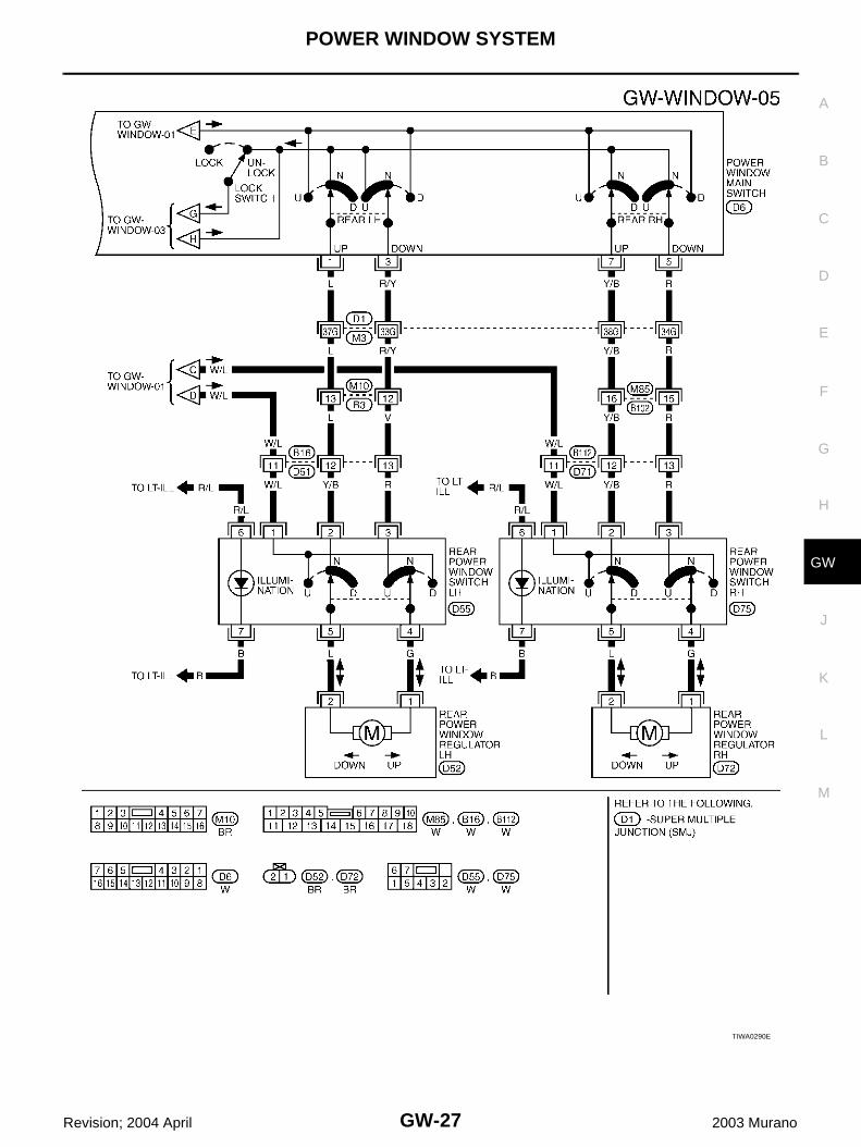
Wiring Diagram – WINDOW – AIS002CQ
TIWA0286E

GW-24
POWER WINDOW SYSTEM
Revision; 2004 April 2003 Murano
TIWA0287E

POWER WINDOW SYSTEM
GW-25
C
D
E
F
G
H
J
K
L
M
A
B
GW
Revision; 2004 April 2003 Murano
TIWA0288E
GW-26
POWER WINDOW SYSTEM
Revision; 2004 April 2003 Murano
TIWA0289E
POWER WINDOW SYSTEM
GW-27
C
D
E
F
G
H
J
K
L
M
A
B
GW
Revision; 2004 April 2003 Murano
TIWA0290E

GW-28
POWER WINDOW SYSTEM
Revision; 2004 April 2003 Murano
Terminal and Reference Value for Power Window Main Switch AIS002CR
Terminal Wire color Item ConditionVoltage (V)(Approx.)
1 LRear LH power window UP signal
when rear LH switch inpower window main switch isUP at operated.
Battery voltage
2 W/B Limit switch and encoder ground — 0
3 R/YRear LH power window DOWN signal
When rear LH switch in power window main switch is DOWN at operated.
Battery voltage
4 L Key cylinder switch lock signalKey position(Neutral → Locked)
5 → 0
5 RRear RH power windowDOWN signal
When rear RH switch in power window main switch is DOWN at operated.
Battery voltage
6 R Key cylinder switch unlock signalKey position(Neutral → Unlocked)
5 → 0
7 Y/BRear RH power window UP signal
When rear RH switch in power window main switch isUP at operated.
Battery voltage
8 G/RFront driver side power window motor UP signal
When power window motor is UP at operated
Battery voltage
9 G/W Limit switch signal
Driver side door window is between fully-open and just before fully-closed position (ON)
0
Driver side door window is between just before fully-closed position and fully-closed position (OFF)
5
10 W/L RAP signal
IGN SW ON Battery voltage
More than 45 seconds after igni-tion switch is turned to OFF
0
When driver side door or passen-ger side open in power window timer is operates
0
11 G/WFront driver sidepower window motor DOWN signal
When power window motor is DOWN at operated
Battery voltage
13 G/Y Encoder pulse signalWhen power window motor oper-ates.
14 BR/W Power window serial linkIGN SW ON or power window timer operating.
15 G/R Encoder power supplyIGN SW ON or power window timer operating.
10
17 B Ground — 0
19 W/R Battery power supply — Battery voltage
OCC3383D
PIIA2344J

POWER WINDOW SYSTEM
GW-29
C
D
E
F
G
H
J
K
L
M
A
B
GW
Revision; 2004 April 2003 Murano
Terminal and Reference Value for Front Power Window Switch (Passenger Side)AIS002CS
Terminal Wire color Item ConditionVoltage (V)(Approx.)
3 W/B Limit switch and encoder ground — 0
4 G/R Encoder power supplyIGN SW ON or power window timer operating.
10
8 LFront passenger side power window motor UP signal
When power window motor isUP at operated.
Battery voltage
9 GFront passenger sidepower window motor DOWN signal
When power window motor is DOWN at operated.
Battery voltage
10 W/R Battery power supply — Battery voltage
11 B Ground — 0
12 G/Y Encoder pulse signalWhen power window motor oper-ates.
15 G/W Limit switch signal
Passenger side door window is between fully-open and just before fully-closed position (ON)
0
Passenger side door window is between just before fully-closed position and fully-closed position (OFF)
5
16 BR/W Power window serial linkIGN SW ON or power window timer operating.
OCC3383D
PIIA2344J

GW-30
POWER WINDOW SYSTEM
Revision; 2004 April 2003 Murano
Terminal and Reference Value for BCM AIS002CT
*: Does not use to control the power window timer usually. Use to control the power window timer when meter and A/C amp. or CAN communication is non-standardcondition.
Work Flow AIS002CZ
1. Check the symptom and customer's requests.2. Understand the outline of system. Refer to GW-18, "System Description"3. According to the trouble diagnosis chart, repair or replace the cause of the malfunction.
Refer to GW-33, "Trouble Diagnosis Symptom Chart" 4. Does power window system operate normally? Yes, GO TO 5, If No, GO TO 3.5. INSPECTION END
Terminal Wire color Item ConditionVoltage (V)(Approx.)
7 W/B Battery power supply — Battery voltage
8 B Ground — 0
10* RDoor switch passenger side signal
ON (Open) 0
OFF (Close) Battery voltage
14* SBDoor switch driver side signal
ON (Open) 0
OFF (close) Battery voltage
28 W/R Power window power supply — Battery voltage
29 W/L RAP signal
IGN SW ON Battery voltage
More then 45 seconds after igni-tion switch is turned to OFF
0
When driver side or passenger side is open in power window timer is operates
0
35 R Ignition switch (ON or START) Ignition switch (ON or START position)
Battery voltage
70 L CAN H — —
71 Y CAN L — —
74 BR/W Power window link signalIgnition switch is ON or power window retained power operation is activated.
PIIA2344J

POWER WINDOW SYSTEM
GW-31
C
D
E
F
G
H
J
K
L
M
A
B
GW
Revision; 2004 April 2003 Murano
CONSULT-II Inspection Procedure AIS002D0
CAUTION:If CONSULT-II is used with no connection of CONSULT-II CONVERTER, malfunction might be detectedin self-diagnosis depending on control unit which carry out CAN communication.1. Turn ignition switch “ON”.2. Connect “CONSULT-II” to the data link connector.
3. Turn ignition switch “ON”.4. Touch “START (NISSAN BASED VHCL)”.
5. Touch “BCM”.If “BCM” is not indicated, go to Refer to GI-38 , “CONSULT-IIDate Link Connector (DLC) Circuit”
6. Touch “RETAINED PWR”.
PHIA0096E
MBIB0233E
LIIA0033E
LIIA0163E

GW-32
POWER WINDOW SYSTEM
Revision; 2004 April 2003 Murano
7. Select diagnosis mode.“ACTIVE TEST” and “WORK SUPPORT” are available.
ACTIVE TEST
WORK SUPPORT
DATA MONITOR
SEL274W
Test Item Description
RETAINED PWR
This test is able to supply RAP signal (power) from BCM (body control module) to power window system and power sunroof system (if equipped). Those systems can be operated when turning on “RETAINED PWR” on CONSULT-II screen even if the ignition switch is turned OFF.
NOTE:During this test, CONSULT-II can be operated with ignition switch in “OFF” position. “RETAINED PWR” should be turned “ON” or “OFF” on CONSULT-II screen when ignition switch is ON. Then turn ignition switch OFF to check retained power operation. CONSULT-II might be stuck if “RETAINED PWR” is turned to “ON” or “OFF” on CONSULT-II screen when ignition switch is OFF.
POWER WINDOW DOWNThis test able to transmitted of power window down signal from BCM to power window main switch and front power window switch (passenger side).
Work item Description
RETAINED PWRRAP signal’s power supply period can be changed by mode setting. Selects RAP signal’s power supply period between three steps
● MODE1 (45 sec.) / MODE2 (OFF) / MODE 3 (2 min.).
Work item Description
IGN ON SW Indicates (ON / OFF) condition of ignition switch
DOOR SW–DR Indicates (ON / OFF) condition of front door switch driver side
DOOE SW–AS Indicates (ON / OFF) condition of front door switch passenger side
LOCK SW DR/ASIndicates (ON / OFF) condition of lock signal from lock and unlock switch on power window main switch or front power window switch (passenger side).
UNLK SW DR/ASIndicates (ON / OFF) condition of unlock signal from lock and unlock switch on power window main switch or front power window switch (passenger side).
KEY CYL LK-SW Indicates (ON / OFF) condition of lock signal from key cylinder.
KEY CYL UN-SW Indicates (ON / OFF) condition of unlock signal from key cylinder.

POWER WINDOW SYSTEM
GW-33
C
D
E
F
G
H
J
K
L
M
A
B
GW
Revision; 2004 April 2003 Murano
Trouble Diagnosis Symptom Chart AIS002D1
● Make sure other systems using the signal of the following systems operate normally.
Symptom Repair order Refer to page
None of the power windows can be operated using any switch.
1. BCM power supply and ground circuit check GW-34
2. Power window main switch power supply and ground circuit check
GW-35
3. Power window serial link check GW-55
4. Replace BCM. BCS-36
Driver side power window alone does not operate.
1. Power window regulator (driver side) circuit check
GW-37
2. Replace power window main switch EI-30
Front passenger side power window alone does not operate.
1. Front power window switch (passenger side) power and ground circuit check
GW-36
2. Power window serial link check GW-55
3. Front power window regulator (passenger side) circuit check
GW-38
4. Replace BCM. BCS-36
Rear LH side power window alone does not operate.1. Rear power window regulator (LH) circuit check
GW-39
Rear RH side power window alone does not operate.1. Rear power window regulator (RH) circuit check
GW-41
Anti-pinch system does not operate normally (driver side).
1. Door window sliding part malfunction
● A foreign material adheres to window glass or glass run rubber.
● Glass run rubber wear or deformation.
● Sash is tilted too much, or no enough.
—
2. Limit switch adjusting GW-60
3. Limit switch circuit check (driver side) GW-43
4. Encoder circuit check (driver side) GW-46
Anti-pinch system does not operate normally (passenger side).
1. Door window sliding part malfunction
● A foreign material adheres to window glass or glass run rubber.
● Glass run rubber wear or deformation.
● Sash is tilted too much, or no enough.
—
2. Limit switch adjusting GW-60
3. Limit switch circuit check (passenger side) GW-44
4. Encoder circuit check (passenger side) GW-48
Power window retained power operation does not operate prop-erly.
1. Check the retained power operation mode setting.
GW-32
2. Door switch check GW-51
3. Replace BCM. BCS-36
Does not operate by key cylinder switch.1. Door key cylinder switch check GW-53
2. Replace power window main switch EI-30
Power window lock switch does not function.1. Power window serial link check GW-55
2. Power window lock switch check GW-57
Auto operation does not operate but manual operate normally.(driver side)
1. Encoder circuit check (driver side) GW-46
2. Replace power window main switch EI-30

GW-34
POWER WINDOW SYSTEM
Revision; 2004 April 2003 Murano
BCM Power Supply and Ground Circuit Check AIS002D3
1. CHECK FUSE
● Check 10A fuse [No.1, located in fuse block (J/B)[● Check 50A fusible link (letter F located in the fuse and fusible link box)NOTE:Refer to GW-17, "Component Parts and Harness Connector Location" .OK or NGOK >> GO TO 2.NG >> If fuse is blown, be sure to eliminate cause of malfunction before installing new fuse. Refer to PG-
3, "POWER SUPPLY ROUTING CIRCUIT" .
2. CHECK POWER SUPPLY CIRCUIT
1. Turn ignition switch ON.2. Check voltage between BCM connector M35, E118 terminal 7, 35 and ground.
OK or NGOK >> GO TO 3.NG >> Check BCM power supply circuit for open or short.
3. CHECK GROUND CIRCUIT
1. Turn ignition switch OFF.2. Disconnect BCM connector.3. Check continuity between BCM connector E118 terminal 8 and ground.
OK or NGOK >> BCM power supply and ground circuit is OK.NG >> Check BCM ground circuit for open or short.
Auto operation does not operate but manual operate normally.(passenger side)
1. Encoder circuit check (passenger side) GW-48
2. Replace front power window switch (passen-ger side)
EI-30
Symptom Repair order Refer to page
7 (W/B) – Ground : Battery voltage35 (R) – Ground : Battery voltage
PIIA3010E
8 (B) – Ground : Continuity should exist.
PIIA1127E

POWER WINDOW SYSTEM
GW-35
C
D
E
F
G
H
J
K
L
M
A
B
GW
Revision; 2004 April 2003 Murano
Power Window Main Switch Power Supply Circuit Check AIS002D5
1. CHECK POWER SUPPLY CIRCUIT
1. Turn ignition switch ON.2. Check voltage between power window main switch connector D6, D7 terminals 10, 19 and ground.
OK or NGOK >> Power window main switch power supply and ground
circuit is OK.NG >> GO TO 2.
2. CHECK GROUND CIRCUIT
1. Turn ignition switch OFF.2. Disconnect power window main switch connector.3. Check continuity between power window main switch connector D7 terminal 17 and ground.
OK or NGOK >> GO TO 3.NG >> Repair or replace harness.
3. CHECK HARNESS CONTINUITY
1. Disconnect BCM connector.2. Check continuity between BCM connector M35 terminals 28, 29 and power window main switch connec-
tor D6, D7 terminal 10, 19.
OK or NGOK >> GO TO 4.NG >> Repair or replace harness between BCM and power
window main switch.
10 (W/L) – Ground : Battery voltage19 (W/R) – Ground : Battery voltage
PIIA4171E
17 (B) – Ground : Continuity should exist.
PIIA4172E
28 (W/R) – 19 (W/R) : Continuity should exist.29 (W/L) – 10 (W/L) : Continuity should exist.
PIIA4173E

GW-36
POWER WINDOW SYSTEM
Revision; 2004 April 2003 Murano
4. CHECK BCM OUTPUT SIGNAL
1. Connect BCM connector. 2. Turn ignition switch ON.3. Check voltage between BCM connector M35 terminal 28, 29 and ground.
OK or NGOK >> Check the condition of the harness and the connector.NG >> Replace BCM.
Front Power Window Switch (Passenger Side) Power Supply and Ground Cir-cuit Check AIS002D6
1. CHECK POWER SUPPLY CIRCUIT
1. Turn ignition switch ON.2. Check voltage between front power window switch (passenger side) connector D35 terminal 10 and
ground.
OK or NGOK >> Front power window switch (passenger side) power sup-
ply and ground circuit is OK.NG >> GO TO 2.
2. CHECK GROUND CIRCUIT
1. Turn ignition switch OFF.2. Disconnect front power window switch (passenger side) connector.3. Check continuity between front power window switch (passenger side) connector D35 terminal 11 and
ground.
OK or NGOK >> GO TO 3.NG >> Repair or replace harness.
28 (W/R) – Ground : Battery voltage29 (W/L) – Ground : Battery voltage
PIIA1419E
10 (W/R) – Ground : Battery voltage
PIIA4174E
11 (B) – Ground : Continuity should exist.
PIIA4175E

POWER WINDOW SYSTEM
GW-37
C
D
E
F
G
H
J
K
L
M
A
B
GW
Revision; 2004 April 2003 Murano
3. CHECK HARNESS CONTINUITY
1. Disconnect BCM connector.2. Check continuity between BCM connector M35 terminal 28 and front power window switch (passenger
side) connector D35 terminal 10.
OK or NGOK >> GO TO 4.NG >> Repair or replace harness between BCM and front
power window switch (passenger side).
4. CHECK BCM OUTPUT SIGNAL
1. Connect BCM connector.2. Turn ignition switch ON.3. Check voltage between BCM connector M35 terminal 28 and ground.
OK or NGOK >> Check the condition of the harness and the connector.NG >> Replace BCM.
Front Power Window Regulator (Driver Side) Circuit Check AIS002D8
1. CHECK POWER WINDOW MAIN SWITCH OUTPUT SIGNAL
1. Turn igniting switch ON.2. Check voltage between power window main switch connector D6 terminals 8, 11 and ground.
OK or NGOK >> GO TO 2.NG >> Replace power window main switch.
28 (W/R) – 10 (W/R) : Continuity should exist.
PIIA4176E
28 (W/R) – Ground : Battery voltage
PIIA4222E
ConnectorTerminals (Wire color) Condition of power
window main switchVoltage (V)(Approx.)(+) (–)
D6
8 (G/R)
Ground
Up Battery voltage
Down 0
11 (G/W)Up 0
Down Battery voltage
PIIA4179E

GW-38
POWER WINDOW SYSTEM
Revision; 2004 April 2003 Murano
2. CHECK HARNESS CONTINUITY
1. Turn ignition switch OFF.2. Disconnect power window main switch and front power window regulator (driver side) connector.3. Check continuity between power window main switch connector D6 terminal 8, 11 and front power window
regulator (driver side) connector D8 terminals 1,2.
OK or NGOK >> Replace front power window motor (driver side).NG >> Repair or replace harness between power window main
switch and front power window regulator (driver side).
Front Power Window Regulator (Passenger Side) Circuit Check AIS002DA
1. CHECK FRONT POWER WINDOW SWITCH (PASSENGER SIDE) OUTPUT SIGNAL
1. Turn igniting switch ON.2. Check voltage between front power window switch (passenger
side) connector D35 terminals 8, 9 and ground.
*: Power window main switch or front power window switch (passenger side)
OK or NGOK >> GO TO 2.NG >> Replace front power window switch (passenger side).
2. CHECK HARNESS CONTINUITY
1. Turn ignition switch OFF.2. Disconnect front power window switch (passenger side) and front power window regulator (passenger
side) connector.3. Check continuity between front power window switch (passenger side) connector D35 terminals 8,9 and
front power window regulator (passenger side) connector D36 terminals 1, 2.
OK or NGOK >> Replace front power window motor (passenger side).NG >> Repair or replace harness between front power window
switch (passenger side) and front power window regula-tor (passenger side).
8 (G/R) – 2 (G/R) : Continuity should exist.11 (G/W) – 1 (G/W) : Continuity should exist.
PIIA4178E
ConnectorTerminals (Wire color)
Condition of switch*Voltage (V)(Approx.)(+) (–)
D35
8 (L)
Ground
Up Battery voltage
Down 0
9 (G)Up 0
Down Battery voltage PIIA4182E
8 (L) – 2 (L) : Continuity should exist.9 (G) – 1 (G) : Continuity should exist.
PIIA4181E

POWER WINDOW SYSTEM
GW-39
C
D
E
F
G
H
J
K
L
M
A
B
GW
Revision; 2004 April 2003 Murano
Rear Power Window Regulator (LH) Circuit Check AIS002DB
1. CHECK REAR POWER WINDOW SWITCH (LH) OUTPUT SIGNAL
1. Turn ignition switch OFF.2. Disconnect rear power window regulator (LH).3. Turn ignition switch ON.4. Check voltage between rear power window switch (LH) connec-
tor D52 terminals 1, 2 and ground.
*: Power window main switch or rear power window switch LH
OK or NGOK >> Replace rear power window motor (LH).NG >> GO TO 2.
2. CHECK HARNESS CONTINUITY 1
1. Turn ignition switch OFF.2. Disconnect rear power window switch (LH) connector.3. Check continuity between rear power window switch (LH) connector D55 terminal 4, 5 and rear power
window regulator (LH) connector D52 terminals 1, 2.
OK or NGOK >> GO TO 3.NG >> Repair or replace harness between rear power window
switch (LH) and rear power window regulator (LH).
3. CHECK REAR POWER WINDOW SWITCH (LH) POWER SUPPLY
1. Connect rear power window switch (LH) connector.2. Turn ignition switch ON.3. Check voltage between rear power window switch (LH) connector D55 terminal 1 and ground.
OK or NGOK >> GO TO 4.NG >> Repair or replace harness.
ConnectorTerminals (Wire color)
Condition of switch*Voltage (V)(Approx.)(+) (–)
D52
1 (G)
Ground
Up 0
Down Battery voltage
2 (L)Up Battery voltage
Down 0PIIA4183E
4 (G) – 1 (G) : Continuity should exist.5 (L) – 2 (L) : Continuity should exist.
PIIA4184E
1 (W/L) – Ground : Battery voltage
PIIA4185E

GW-40
POWER WINDOW SYSTEM
Revision; 2004 April 2003 Murano
4. CHECK REAR POWER WINDOW SWITCH LH
1. Turn igniting switch OFF.2. Disconnect rear power window switch (LH) connector.3. Check continuity between rear power window switch (LH) connector D55 terminals 1, 2, 3 and 4, 5.
OK or NGOK >> GO TO 5.NG >> Replace rear power window switch (LH).
5. CHECK POWER WINDOW MAIN SWITCH OUTPUT SIGNAL
1. Turn ignition switch ON.2. Power window main switch is operated, check voltage between power window main switch connector D6
terminals 1, 3 and ground.
OK or NGOK >> GO TO 6.NG >> Replace power window main switch.
6. CHECK HARNESS CONTINUITY
1. Turn ignition switch OFF.2. Disconnect power window main switch connector.3. Check continuity between power window main switch connector D6 terminals 1, 3 and rear power window
switch (LH) connector D55 terminals 2, 3.
OK or NGOK >> Check the condition of the harness and the connector.NG >> Repair or replace harness between power window main
switch and rear power window switch (LH).
Terminal Switch condition Continuity
14
DOWN position
Yes3 Free
15
UP position
2 Free
PIIA4186E
ConnectorTerminals (Wire color)
ConditionVoltage (V)(Approx.)(+) (-)
D6
1 (Y)
Ground
Up Battery voltage
Down 0
3 (R)Up 0
Down Battery voltage
PIIA4187E
1 (Y) – 2 (Y) : Continuity should exist.3 (R) – 3 (R) : Continuity should exist.
PIIA4188E
POWER WINDOW SYSTEM
GW-41
C
D
E
F
G
H
J
K
L
M
A
B
GW
Revision; 2004 April 2003 Murano
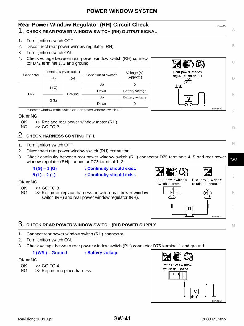
Rear Power Window Regulator (RH) Circuit Check AIS002DC
1. CHECK REAR POWER WINDOW SWITCH (RH) OUTPUT SIGNAL
1. Turn ignition switch OFF.2. Disconnect rear power window regulator (RH).3. Turn ignition switch ON.4. Check voltage between rear power window switch (RH) connec-
tor D72 terminal 1, 2 and ground.
*: Power window main switch or rear power window switch RH
OK or NGOK >> Replace rear power window motor (RH).NG >> GO TO 2.
2. CHECK HARNESS CONTINUITY 1
1. Turn ignition switch OFF.2. Disconnect rear power window switch (RH) connector.3. Check continuity between rear power window switch (RH) connector D75 terminals 4, 5 and rear power
window regulator (RH) connector D72 terminal 1, 2.
OK or NGOK >> GO TO 3.NG >> Repair or replace harness between rear power window
switch (RH) and rear power window regulator (RH).
3. CHECK REAR POWER WINDOW SWITCH (RH) POWER SUPPLY
1. Connect rear power window switch (RH) connector.2. Turn ignition switch ON.3. Check voltage between rear power window switch (RH) connector D75 terminal 1 and ground.
OK or NGOK >> GO TO 4.NG >> Repair or replace harness.
ConnectorTerminals (Wire color)
Condition of switch*Voltage (V)(Approx.)(+) (–)
D72
1 (G)
Ground
Up 0
Down Battery voltage
2 (L)Up Battery voltage
Down 0PIIA4183E
4 (G) – 1 (G) : Continuity should exist.5 (L) – 2 (L) : Continuity should exist.
PIIA4184E
1 (W/L) – Ground : Battery voltage
PIIA4185E
GW-42
POWER WINDOW SYSTEM
Revision; 2004 April 2003 Murano
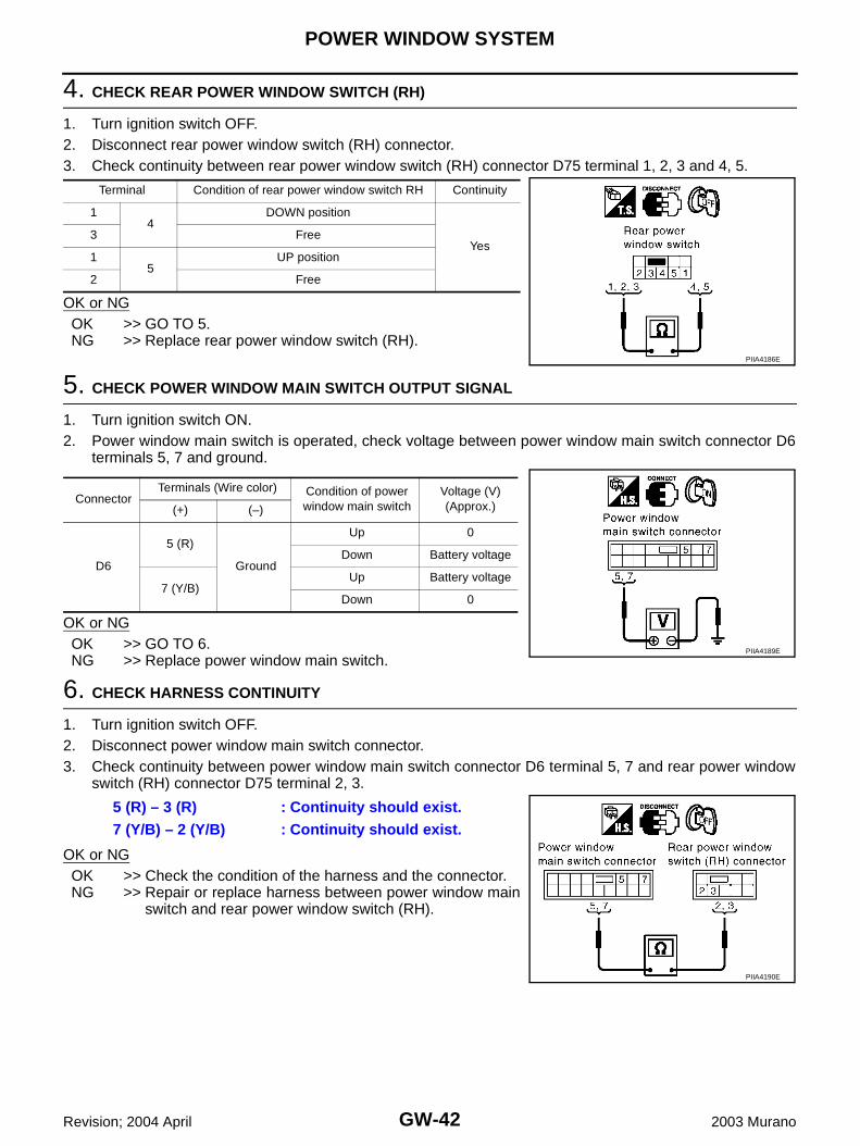
4. CHECK REAR POWER WINDOW SWITCH (RH)
1. Turn ignition switch OFF.2. Disconnect rear power window switch (RH) connector.3. Check continuity between rear power window switch (RH) connector D75 terminal 1, 2, 3 and 4, 5.
OK or NGOK >> GO TO 5.NG >> Replace rear power window switch (RH).
5. CHECK POWER WINDOW MAIN SWITCH OUTPUT SIGNAL
1. Turn ignition switch ON.2. Power window main switch is operated, check voltage between power window main switch connector D6
terminals 5, 7 and ground.
OK or NGOK >> GO TO 6.NG >> Replace power window main switch.
6. CHECK HARNESS CONTINUITY
1. Turn ignition switch OFF.2. Disconnect power window main switch connector.3. Check continuity between power window main switch connector D6 terminal 5, 7 and rear power window
switch (RH) connector D75 terminal 2, 3.
OK or NGOK >> Check the condition of the harness and the connector.NG >> Repair or replace harness between power window main
switch and rear power window switch (RH).
Terminal Condition of rear power window switch RH Continuity
14
DOWN position
Yes3 Free
15
UP position
2 Free
PIIA4186E
ConnectorTerminals (Wire color) Condition of power
window main switchVoltage (V)(Approx.)(+) (–)
D6
5 (R)
Ground
Up 0
Down Battery voltage
7 (Y/B)Up Battery voltage
Down 0
PIIA4189E
5 (R) – 3 (R) : Continuity should exist.7 (Y/B) – 2 (Y/B) : Continuity should exist.
PIIA4190E

POWER WINDOW SYSTEM
GW-43
C
D
E
F
G
H
J
K
L
M
A
B
GW
Revision; 2004 April 2003 Murano
Limit Switch Circuit Check (Driver Side) AIS002DF
1. CHECK DRIVER DOOR MAIN SWITCH LIMIT SIGNAL
1. Turn ignition switch ON.2. Check voltage between front power window regulator (driver
side) connector and ground.
OK or NGOK >> Limit switch circuit is OK.NG >> GO TO 2.
2. CHECK GROUND CIRCUIT
1. Turn ignition switch OFF.2. Disconnect front power window regulator (driver side) connector.3. Check continuity between front power window regulator (driver side) connector D8 terminal 6 and ground.
OK or NGOK >> GO TO 4.NG >> GO TO 3.
3. CHECK HARNESS CONTINUITY 1
1. Disconnect power window main switch connector.2. Check continuity between power window main switch connector D6 terminal 2 and front power window
regulator (driver side) connector D8 terminal 6.
OK or NGOK >> Replace power window main switch.NG >> Repair or replace harness between power window main
switch and front power window regulator (driver side).
ConnectorTerminals (Wire color)
Condition of windowVoltage (V)(Approx.)(+) (–)
D8 5 (G/W) Ground
Driver side door window is between fully-open and just before fully-closed position (ON)
0
Driver side door window is between just before fully-closed position and fully-closed position (OFF)
5 PIIA4191E
6 (W/B) – Ground : Continuity should exist.
PIIA4192E
2 (W/B) – 6 (W/B) : Continuity should exist.
PIIA4193E

GW-44
POWER WINDOW SYSTEM
Revision; 2004 April 2003 Murano
4. CHECK POWER WINDOW MAIN SWITCH OUTPUT SIGNAL
1. Turn ignition switch ON.2. Check voltage between power window main switch connector D6 terminal 9 and ground.
OK or NGOK >> GO TO 5.NG >> Replace power window main switch.
5. CHECK HARNESS CONTINUITY 2
1. Turn ignition switch OFF.2. Disconnect power window main switch connector.3. Check continuity between power window main switch connector D6 terminal 9 and front power window
regulator (driver side) connector D8 terminal 5.
OK or NGOK >> Replace front power window regulator (driver side).NG >> Repair or replace harness between and power window
main switch front power window regulator (driver side).
Limit Switch Circuit Check (Passenger Side) AIS002DH
1. CHECK FRONT POWER WINDOW SWITCH (PASSENGER SIDE) LIMIT SIGNAL
1. Turn ignition switch ON.2. Check voltage between front power window regulator (passenger side) connector and ground.
OK or NGOK >> Limit switch circuit is OK.NG >> GO TO 2.
9 (G/W) – Ground : Approx. 5V
PIIA4194E
9 (G/W) – 5 (G/W) : Continuity should exist.
PIIA4195E
ConnectorTerminals (Wire color)
Condition of windowVoltage (V)(Approx.)(+) (–)
D36 5 (G/W) Ground
Passenger side door window is between fully-open and just before fully-closed posi-tion (ON)
0
Passenger side door window is between just before fully-closed position and fully-closed position (OFF)
5
PIIA4197E

POWER WINDOW SYSTEM
GW-45
C
D
E
F
G
H
J
K
L
M
A
B
GW
Revision; 2004 April 2003 Murano
2. CHECK GROUND CIRCUIT
1. Turn ignition switch OFF.2. Disconnect front power window regulator (passenger side) connector.3. Check continuity between front power window regulator (passenger side) connector D36 terminal 6 and
ground.
OK or NGOK >> GO TO 4.NG >> GO TO 3.
3. CHECK HARNESS CONTINUITY 1
1. Disconnect front power window switch (passenger side) connector.2. Check continuity between front power window switch (passenger side) connector D35 terminal 3 and front
power window regulator (passenger side) connector D36 terminal 6.
OK or NGOK >> Replace front power window switch (passenger side).NG >> Repair or replace harness between front power window
switch (passenger side) and front power window regula-tor (passenger side).
4. CHECK FRONT POWER WINDOW SWITCH (PASSENGER SIDE) OUTPUT SIGNAL
1. Turn ignition switch ON.2. Check voltage between front power window switch (passenger side) connector D35 terminal 15 and
ground.
OK or NGOK >> GO TO 5.NG >> Replace front power window switch (passenger side).
6 (W/B) – Ground : Continuity should exist.
PIIA4198E
3 (W/B) – 6 (W/B) : Continuity should exist.
PIIA4199E
15 (G/W) – Ground : Approx. 5V
PIIA4200E

GW-46
POWER WINDOW SYSTEM
Revision; 2004 April 2003 Murano
5. CHECK HARNESS CONTINUITY 2
1. Turn ignition switch OFF.2. Disconnect front power window switch (passenger side) connector.3. Check continuity between front power window switch (passenger side) connector D35 terminal 15 and
front power window regulator (passenger side) connector D36 terminal 5.
OK or NGOK >> Replace front power window regulator (passenger side).NG >> Repair or replace harness between front power window
switch (passenger side) and front power window regula-tor (passenger side).
Encoder Circuit Check (Driver Side) AIS002DJ
1. CHECK FRONT POWER WINDOW REGULATOR (DRIVER SIDE) POWER SUPPLY
1. Turn ignition switch ON.2. Check voltage between front power window regulator (driver side) connector D8 terminal 4 and ground.
OK or NGOK >> GO TO 3.NG >> GO TO 2.
2. CHECK HARNESS CONTINUITY 1
1. Turn ignition switch OFF.2. Disconnect front power window regulator (driver side) and power window main switch.3. Check continuity between power window main switch connector D6 terminal 15 and front power window
regulator (driver side) connector D8 terminal 4.
OK or NGOK >> Replace power window main switch.NG >> Repair or replace harness between power window main
switch connector and front power window regulator(driver side) connector.
15 (G/W) – 5 (G/W) : Continuity should exist.
PIIA4201E
4 (G/R) – Ground : Approx.10V
PIIA4203E
15 (G/R) – 4 (G/R) : Continuity should exist.
PIIA4204E

POWER WINDOW SYSTEM
GW-47
C
D
E
F
G
H
J
K
L
M
A
B
GW
Revision; 2004 April 2003 Murano
3. CHECK GROUND CIRCUIT
1. Turn ignition switch OFF.2. Disconnect front power window regulator (driver side) connector.3. Check continuity between front power window regulator (driver side) connector D8 terminal 6 and round.
OK or NGOK >> GO TO 5.NG >> GO TO 4.
4. CHECK HARNESS CONTINUITY 2
1. Disconnect power window main switch connector.2. Check continuity between power window main switch connector D6 terminal 2 and front power window
regulator (driver side) connector D8 terminal 6.
OK or NGOK >> Replace power window main switch.NG >> Repair or replace harness between power window main
switch and front power window regulator (driver side).
5. CHECK ENCODER SIGNAL
1. Connect front power window regulator (driver side) connector.2. Turn ignition switch ON.3. Check the signal between power window main switch connector and ground with oscilloscope.
OK or NGOK >> Replace power window main switch.NG >> GO TO 6.
6 (W/B) – Ground : Continuity should exist.
PIIA4192E
2 (W/B) – 6 (W/B) : Continuity should exist.
PIIA4193E
ConnectorTerminals (Wire color)
ConditionSignal
(Reference value)(+) (-)
D6 13 (G/Y) Ground opening
PIIA4205E
OCC3383D

GW-48
POWER WINDOW SYSTEM
Revision; 2004 April 2003 Murano
6. CHECK HARNESS CONTINUITY 3
1. Turn ignition switch OFF.2. Disconnect power window main switch and front power window regulator (driver side) connector.3. Check continuity between power window main switch connector D6 terminal 13 and front power window
regulator (driver side) connector D8 terminal 3.
OK or NGOK >> Replace front power window regulator (driver side)NG >> Repair or replace harness between front power window
regulator (driver side) and power window main switch.
Encoder Circuit Check (Front Passenger Side) AIS002DL
1. CHECK FRONT POWER WINDOW REGULATOR (PASSENGER SIDE) POWER SUPPLY
1. Turn ignition switch ON.2. Check voltage between front power window regulator (passenger side) connector D36 terminal 4 and
ground.
OK or NGOK >> GO TO 3.NG >> GO TO 2.
2. CHECK HARNESS CONTINUITY 1
1. Turn ignition switch OFF.2. Disconnect front power window switch (passenger side) and front power window regulator (passenger
side).3. Check continuity between front power window switch (passenger side) connector D35 terminal 4 and
front power window regulator (passenger side) connector D36 terminal 4.
OK or NGOK >> Replace front power window switch (passenger side).NG >> Repair or replace harness between front power window
switch (passenger side) and front power window regula-tor (passenger side).
13 (G/Y) – 3 (G/Y) : Continuity should exist.
PIIA4206E
4 (G/R) – Ground : Approx. 10V
PIIA4207E
4 (G/R) – 4 (G/R) : Continuity should exist.
PIIA4208E

POWER WINDOW SYSTEM
GW-49
C
D
E
F
G
H
J
K
L
M
A
B
GW
Revision; 2004 April 2003 Murano
3. CHECK GROUND CIRCUIT
1. Turn ignition switch OFF.2. Disconnect front power window regulator (passenger side) connector.3. Check continuity between front power window regulator (passenger side) connector D36 terminal 6 and
ground.
OK or NGOK >> GO TO 5.NG >> GO TO 4.
4. CHECK HARNESS CONTINUITY 2
1. Disconnect front power window switch (passenger side) connector.2. Check continuity between front power window switch (passenger side) connector D35 terminal 3 and front
power window regulator (passenger side) connector D36 terminal 6.
OK or NGOK >> Replace front power window switch (passenger side).NG >> Repair or replace harness between front power window
regulator (passenger side) and front power windowswitch (passenger side).
5. CHECK ENCODER SIGNAL
1. Connect front power window regulator (passenger side) connector.2. Turn ignition switch ON.3. Check the signal between front power window switch (passenger side) connector and ground with oscillo-
scope.
OK or NGOK >> Replace front power switch (passenger side).NG >> GO TO 6.
6 (W/B) – Ground : Continuity should exist.
PIIA4198E
3 (W/B) – 6 (W/B) : Continuity should exist.
PIIA4199E
Connec-tor
Terminals (Wire color)Condition
Signal(Reference value)(+) (-)
D35 12 (G/Y) Ground opening
PIIA4209E
OCC3383D

GW-50
POWER WINDOW SYSTEM
Revision; 2004 April 2003 Murano
6. CHECK HARNESS CONTINUITY 3
1. Turn ignition switch OFF.2. Disconnect front power window switch (passenger side) and front power window regulator (passenger
side) connector.3. Check continuity between front power window switch (passenger side) connector D35 terminal 12 and
front power window regulator (passenger side) connector D36 terminal 3.
OK or NGOK >> Replace front power window regulator (passenger side).NG >> Repair or replace harness between front power window
switch (passenger side) and front power window regula-tor (passenger side).
12 (G/Y) – 3 (G/Y) : Continuity should exist.
PIIA4210E

POWER WINDOW SYSTEM
GW-51
C
D
E
F
G
H
J
K
L
M
A
B
GW
Revision; 2004 April 2003 Murano
Door Switch Check AIS002DO
1. CHECK DOOR SWITCH INPUT SIGNAL 1
With CONSULT-IICheck door switches (“DOOR SW-DR” and “DOOR SW-AS”) in “DATA MONITOR” mode with CONSULT-II.
Without CONSULT-IICheck voltage between BCM connector and ground.
OK or NGOK >> Door switch is OK.NG >> GO TO 2.
2. CHECK HARNESS CONTINUITY
1. Disconnect BCM connector.2. Check continuity between BCM connector M34 terminals 10, 14
and front door lock assembly connector D10, D38 terminal 4.
3. Check continuity between BCM connector M34 terminals 10, 14and ground.
OK or NGOK >> GO TO 3.NG >> Repair or replace harness.
Monitor item Condition of door DATA MONITOR
DOOR SW-DROPEN ON
CLOSE OFF
DOOR SW-ASOPEN ON
CLOSE OFF
PIIA2464E
ItemCon-
nector
Terminals (Wire color)Condition
Voltage (V)(Approx.)(+) (–)
Passenger side
M34
10 (R)
Ground
OPEN 0
CLOSE Battery voltage
Driverside
14 (SB)OPEN 0
CLOSE Battery voltage
PIIA2465E
Driver side14 (SB) – 4 (SB) : Continuity should exist.Passenger side10 (R) – 4 (R) : Continuity should exist.
10 (R) – Ground : Continuity should not exist.14 (SB) – Ground : Continuity should not exist.
PIIA4221E

GW-52
POWER WINDOW SYSTEM
Revision; 2004 April 2003 Murano
3. CHECK DOOR SWITCH
Check continuity between front door lock assembly terminals 4 and5.
OK or NGOK >> GO TO 4.NG >> Replace malfunction front door lock assembly.
4. CHECK BCM OUTPUT SIGNAL
1. Connect BCM connector.2. Check voltage between BCM connector and ground.
OK or NGOK >> Check the condition of the harness and the connector.NG >> Replace BCM.
Terminal Condition of door switch Continuity
4 5OPEN No
CLOSE Yes
PIIA4220E
ItemCon-
nector
Terminals (Wire color)Condition
Voltage (V)(Approx.)(+) (–)
Passenger side
M34
10 (R)
Ground
OPEN 0
CLOSE Battery voltage
Driverside
14 (SB)OPEN 0
CLOSE Battery voltage
PIIA2465E

POWER WINDOW SYSTEM
GW-53
C
D
E
F
G
H
J
K
L
M
A
B
GW
Revision; 2004 April 2003 Murano
Front Door Key Cylinder Switch (Driver Side) Check AIS002DP
1. CHECK DOOR KEY CYLINDER SWITCH INPUT SIGNAL
With CONSULT-IICheck door key cylinder switch (“KEY CYL LK SW”, “KEY CYL UNSW”) in “DATA MONITOR” mode with CONSULT-II.
Without CONSULT-IICheck voltage between power window main switch connector andground.
OK or NGOK >> Further inspection is necessary. Refer to symptom
chart.NG >> GO TO 2.
2. CHECK HARNESS CONTINUITY
1. Turn ignition switch OFF.2. Disconnect power window main switch and front door lock assembly (driver side) connector.3. Check continuity between power window main switch connector
D6 terminals 4, 6 and front door lock assembly (driver side) con-nector D10 terminals 1, 6.
OK or NGOK >> GO TO 3.NG >> Repair or replace harness between power window main
switch and front door lock assembly (driver side).
Monitor itemCondition of front door
key cylinderDATA MONITOR
KEY CYL LK-SWLock ON
Neutral / Unlock OFF
KEY CYL UN-SWUnlock ON
Neutral / Lock OFF
ConnectorTerminals (Wire color)
Key position Voltage (V) (Approx.)(+) (–)
D6
4 (L)
Ground
Lock 0
Neutral / Unlock 5
6 (R)Unlock 0
Neutral / Lock 5
PIIA6285E
PIIA4211E
4 (L) – 1 (L) : Continuity should exist.6 (R) – 6 (R) : Continuity should exist.
PIIA4212E

GW-54
POWER WINDOW SYSTEM
Revision; 2004 April 2003 Murano
3. CHECK GROUND CIRCUIT
Check continuity between key cylinder switch (driver side) connectorD10 terminal 5 and ground.
OK or NGOK >> GO TO 4.NG >> Repair or replace harness.
4. CHECK DOOR KEY CYLINDER SWITCH
Check continuity between key cylinder switch terminals 1, 6 and 5.
OK or NGOK >> Further inspection is necessary. Refer to symptom
chart.NG >> Replace key cylinder switch (driver side).
5 (B) – Ground : Continuity should exist.
PIIA4213E
Terminals Key position Continuity
1
5
Neutral / Unlock No
Lock Yes
6Neutral / Lock No
Unlock Yes
PIIA4214E
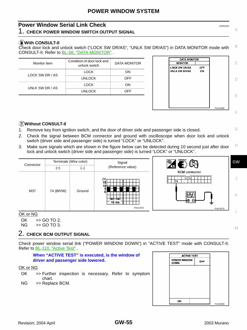
POWER WINDOW SYSTEM
GW-55
C
D
E
F
G
H
J
K
L
M
A
B
GW
Revision; 2004 April 2003 Murano
Power Window Serial Link Check AIS002DR
1. CHECK POWER WINDOW SWITCH OUTPUT SIGNAL
With CONSULT-IICheck door lock and unlock switch (“LOCK SW DR/AS”, “UNLK SW DR/AS”) in DATA MONITOR mode withCONSULT-II. Refer to BL-58, "DATA MONITOR" .
Without CONSULT-II1. Remove key from ignition switch, and the door of driver side and passenger side is closed.2. Check the signal between BCM connector and ground with oscilloscope when door lock and unlock
switch (driver side and passenger side) is turned “LOCK” or “UNLOCK”.3. Make sure signals which are shown in the figure below can be detected during 10 second just after door
lock and unlock switch (driver side and passenger side) is turned “LOCK” or “UNLOCK”.
OK or NGOK >> GO TO 2.NG >> GO TO 3.
2. CHECK BCM OUTPUT SIGNAL
Check power window serial link (“POWER WINDOW DOWN”) in “ACTIVE TEST” mode with CONSULT-II.Refer to BL-110, "Active Test" .
OK or NGOK >> Further inspection is necessary. Refer to symptom
chart.NG >> Replace BCM.
Monitor itemCondition of door lock and
unlock switchDATA MONITOR
LOCK SW DR / ASLOCK ON
UNLOCK OFF
UNLK SW DR / ASLOCK ON
UNLOCK OFF
PIIA6289E
ConnectorTerminals (Wire color) Signal
(Reference value)(+) (–)
M37 74 (BR/W) Ground
PIIA2357EPIIA1297E
When “ACTIVE TEST” is executed, is the window of driver and passenger side lowered.
PIIA3080E

GW-56
POWER WINDOW SYSTEM
Revision; 2004 April 2003 Murano
3. CHECK POWER WINDOW SWITCH GROUND
1. Turn ignition switch OFF.2. Disconnect power window main switch and front power window switch (passenger side) connector.3. Check continuity between power window main switch connector D7 terminal 17 and ground.
4. Check continuity between front power window switch (passenger side) connector D35 terminal 11 andground.
OK or NGOK >> GO TO 4.NG >> Repair or replace harness.
17 (B) – Ground : Continuity should exist.
PIIA4172E
11 (B) – Ground : Continuity should exist.
PIIA4175E
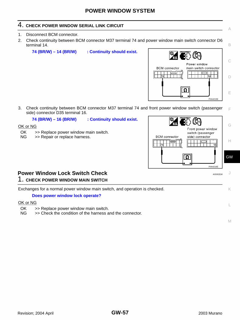
POWER WINDOW SYSTEM
GW-57
C
D
E
F
G
H
J
K
L
M
A
B
GW
Revision; 2004 April 2003 Murano
4. CHECK POWER WINDOW SERIAL LINK CIRCUIT
1. Disconnect BCM connector.2. Check continuity between BCM connector M37 terminal 74 and power window main switch connector D6
terminal 14.
3. Check continuity between BCM connector M37 terminal 74 and front power window switch (passengerside) connector D35 terminal 16.
OK or NGOK >> Replace power window main switch.NG >> Repair or replace harness.
Power Window Lock Switch Check AIS002EM
1. CHECK POWER WINDOW MAIN SWITCH
Exchanges for a normal power window main switch, and operation is checked.
OK or NGOK >> Replace power window main switch.NG >> Check the condition of the harness and the connector.
74 (BR/W) – 14 (BR/W) : Continuity should exist.
PIIA4215E
74 (BR/W) – 16 (BR/W) : Continuity should exist.
PIIA4216E
Does power window lock operate?

GW-58
FRONT DOOR GLASS AND REGULATOR
Revision; 2004 April 2003 Murano
FRONT DOOR GLASS AND REGULATOR PFP:80300
Removal and Installation AIS005AL
REMOVAL1. Remove the front door finisher. Refer to EI-30, "DOOR FINISHER" .2. Operate the power window main switch to raise/lower the door
window until the glass mounting bolts can be seen.3. Remove the glass mounting bolts.4. Remove the module stop bolts.
5. While holding the door window, raise it at the rear end to pull theglass out of the sash toward the outside of the door.
1. Door glass 2. Regulator assembly 3. Power window motor
4. Module assembly
PIIA3786E
PIIA3789E
PIIA4004E

FRONT DOOR GLASS AND REGULATOR
GW-59
C
D
E
F
G
H
J
K
L
M
A
B
GW
Revision; 2004 April 2003 Murano
6. Remove the mounting bolts, and remove the module assembly.7. Disconnect the harness connector for the module assembly, and
unclip the harness from the back.
INSTALLATIONInstall in the reverse order of removal.
INSPECTION AFTER REMOVALCheck the regulator assembly for the following items. If a malfunc-tion is detected, replace or grease it.● Wire wear● Regulator deformation● Grease condition for each sliding partThe arrows in the figure show the application points of the bodygrease.
DISASSEMBLY AND ASSEMBLYRemove the power window motor and guide rail from the moduleassembly.
SIIA0287E
PIIA3787E
PIIA3788E

GW-60
FRONT DOOR GLASS AND REGULATOR
Revision; 2004 April 2003 Murano
SETTING AFTER INSTALLATIONResetting of Limit SwitchIf any of the following work has been done, reset the limit switch (integrated in the motor).● Removal and installation of the regulator.● Removal and installation of the motor from the regulator.● Operate the regulators as a unit.● Removal and installation of the glass.● Removal and installation of the glass run.
ResettingAfter installing each component to the vehicle, follow the steps below.1. Remove the motor from regulator.2. Connect the connector. Rotate the motor unit with power window switch for more than 5 sec in glass rais-
ing direction.3. Install motor to regulator.4. Raise glass to the top position.
CAUTION:Do not use Auto switch to raise the glass to the top position.
FITTING INSPECTION● Make sure the glass is securely fit into the glass run groove.● Lower the glass slightly [approx. 10 to 20 mm (0.39 to 0.79 in)] and make sure the clearance to the sash is
parallel. If the clearance between the glass and sash is not parallel, loosen the regulator mounting bolts,guide rail mounting bolts, and glass and guide rail mounting bolts to correct the glass position.

REAR DOOR GLASS AND REGULATOR
GW-61
C
D
E
F
G
H
J
K
L
M
A
B
GW
Revision; 2004 April 2003 Murano
REAR DOOR GLASS AND REGULATOR PFP:82300
Removal and Installation AIS005AM
REMOVAL1. Remove the rear door finisher. Refer to EI-30, "DOOR FINISHER" .2. Remove the rear door outside molding. Refer to EI-23, "DOOR OUTSIDE MOLDING" .3. Remove the sealing screen.4. Remove the rear lower sash.5. Operate the power window switch to raise/lower the door win-
dow until the glass mounting bolts can be seen.6. Remove the glass mounting bolts, and place the glass on the
inner bottom of the panel.
1. Door glass 2. Regulator assembly 3. Power window motor
PIIA3790E
PIIA3791E

GW-62
REAR DOOR GLASS AND REGULATOR
Revision; 2004 April 2003 Murano
7. Remove the regulator mounting bolts, and remove the regulatorfrom the panel.
8. Disconnect the connector for the regulator assembly.
INSTALLATIONInstall in the reverse order of removal.
INSPECTION AFTER REMOVALCheck the regulator assembly for the following items. If a malfunction is detected, replace or grease it.● Wire wear● Regulator deformation● Grease condition for each sliding partThe arrows in the figure show the application points of the grease“Dow Corning Moly Coat SK 623” or equivalent.
FITTING INSPECTION● Make sure the glass is securely fit into the glass run groove.● Lower the glass slightly [approx. 10 to 20 mm (0.39 to 0.79 in)], and make sure the clearance to the sash
is parallel. If the clearance between the glass and sash is not parallel, loosen the regulator mounting bolts,guide rail mounting bolts, and glass and carrier plate mounting bolts to correct the glass position.
PIIA3792E
PIIA6327J
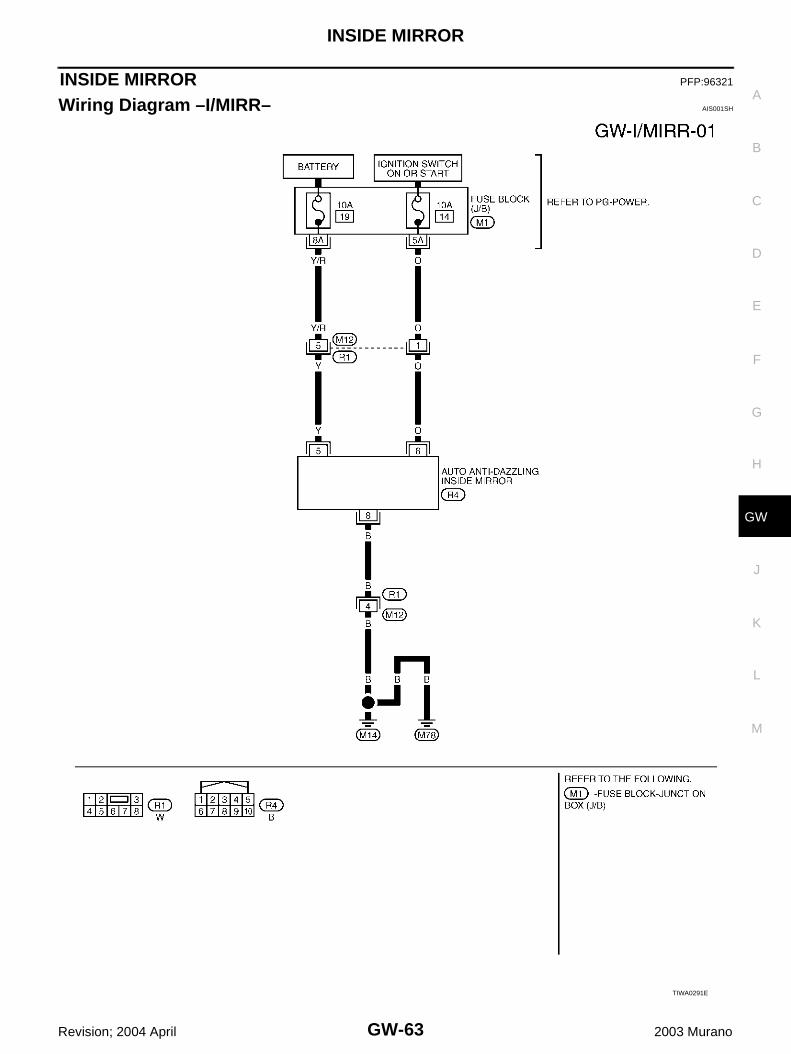
INSIDE MIRROR
GW-63
C
D
E
F
G
H
J
K
L
M
A
B
GW
Revision; 2004 April 2003 Murano
INSIDE MIRROR PFP:96321
Wiring Diagram –I/MIRR– AIS001SH
TIWA0291E

GW-64
INSIDE MIRROR
Revision; 2004 April 2003 Murano
Removal and Installation AIS005AN
CAUTION:Apply Genuine Mirror Adhesive or equivalent to bonding surface of mounting bracket. Refer to GI-46,"RECOMMENDED CHEMICAL PRODUCTS AND SEALANTS" .
REMOVAL1. Remove inside mirror finisher (if equipped).2. Remove screw of mirror base.3. Slide the mirror upward to remove.4. Disconnect the connector (if equipped).
INSTALLATIONInstall in the reverse order of removal.
1. Inside mirror 2. Inside mirror finisher (if equipped)
PIIA9845E

REAR WINDOW DEFOGGER
GW-65
C
D
E
F
G
H
J
K
L
M
A
B
GW
Revision; 2004 April 2003 Murano
REAR WINDOW DEFOGGER PFP:25350
Component Parts and Harness Connector Location AIS002IB
System Description AIS002IC
The rear window defogger system is controlled by BCM (Body Control Module) and IPDM E/R (IntelligentPower Distribution Module Engine Room). The rear window defogger operates only for approximately 15 minutes. Power is at all times supplied● through 20A fuse [No. 77, and 78, located in the IPDM E/R] ● to rear window defogger relay terminals 3 and 6.● through 15A fuse [No. 28, located in the fuse block (J/B)]● to A/C and AV switch terminal 1.● through 50A fusible link [letter F , located in the fuse block (J/B)]
PIIA4682E

GW-66
REAR WINDOW DEFOGGER
Revision; 2004 April 2003 Murano
● to BCM terminal 7.With the ignition switch turned to ON or START position, Power is supplied● through 10A fuse [No.12, located in the fuse block (J/B)]● to rear window defogger relay terminal 1.● through 10A fuse [No.1, located in the fuse block (J/B)]● to BCM terminal 35.● through 10A fuse [No. 6, located in the fuse block (J/B)]● to A/C and AV switch terminal 2.Ground is supplied ● to BCM terminal 8● through body grounds E13, E26 and E28.● to A/C and AV switch terminal 5● through body grounds M14 and M78.● to internal CPU of IPDM E/R terminals 14 and 45● through body grounds E13, E26 and E28. When A/C and AV switch (rear window defogger switch) is turned to ON, Ground is supplied ● to BCM terminal 69● through A/C and AV switch terminal 16 ● through A/C and AV switch terminal 5● through body grounds M14 and M78.Then rear window defogger switch is illuminated.Then BCM recognizes that rear window defogger switch is turned to ON. Then it sends rear window defogger switch signals to IPDM E/R and display control unit (with navigation) ordisplay unit (without navigation) via DATA LINE (CAN H, CAN L).When display control unit (with navigation) or display unit (without navigation) receives rear window defoggerswitch signals, and display on the screen.When IPDM E/R receives rear window defogger switch signals, Ground is supplied● to rear window defogger relay terminal 2,● through IPDM E/R terminal 54,● through internal CPU of IPDM E/R and IPDM E/R terminal 45.● through body grounds E13, E26 and E28, and then rear window defogger relay is energized. When rear window defogger relay is turned ON, Signals are transmitted,● through rear window defogger relay terminals 5● to rear window defogger terminal 1,● Rear window defogger terminal 2, is grounded through body grounds B7 and B20. With power and ground supplied, rear window defogger filaments heat and defog the rear window.When rear window defogger relay is turned to ON, (with door mirror defogger)Power is supplied● through rear window defogger relay terminals 5 and 7,● through fuse block (J/B) terminal 2C,● through 10A fuse [No. 8, located in the fuse block (J/B)],● through fuse block (J/B) terminal 5B.● to door mirror defogger (Driver side and passenger side) terminal 1.Door mirror defogger (Driver side and passenger side) terminal 5 is grounded through body grounds M14 andM78.With power and ground supplied, rear window defogger filaments heat and defog the rear window and doormirror defogger filaments heat and defog the mirror.

REAR WINDOW DEFOGGER
GW-67
C
D
E
F
G
H
J
K
L
M
A
B
GW
Revision; 2004 April 2003 Murano
CAN Communication System Description AIS003KN
CAN (Controller Area Network) is a serial communication line for real time application. It is an on-vehicle mul-tiplex communication line with high data communication speed and excellent error detection ability. Many elec-tronic control units are equipped onto a vehicle, and each control unit shares information and links with othercontrol units during operation (not independent). In CAN communication, control units are connected with 2communication lines (CAN H line, CAN L line) allowing a high rate of information transmission with less wiring.Each control unit transmits/receives data but selectively reads required data only.
CAN Communication Unit For 2WD Models AIS003KO
×: Applicable
Body type Wagon
Axle 2WD
Engine VQ35DE
Transmission CVT
Brake control ABS VDC
Low tire pressure warning system
× × × × × × × ×
Navigation system × × × × × × × ×
Automatic drive positioner × × × × × × × ×
CAN communication unit
ECM × × × × × × × × × × × × × × × ×
TCM × × × × × × × × × × × × × × × ×
Low tire pressure warning control unit
× × × × × × × ×
Display unit × × × × × × × ×
Display control unit × × × × × × × ×
Data link connector × × × × × × × × × × × × × × × ×
BCM × × × × × × × × × × × × × × × ×
Unified meter and A/C amp. × × × × × × × × × × × × × × × ×
Steering angle sensor × × × × × × × ×
Driver seat control unit × × × × × × × ×
ABS actuator and electric unit (control unit)
× × × × × × × × × × × × × × × ×
IPDM E/R × × × × × × × × × × × × × × × ×
CAN communication typeGW-68, "TYPE 1/TYPE 2/TYPE 3/TYPE 4/TYPE
5/TYPE 6/TYPE 7/TYPE 8"GW-73, "TYPE 9/TYPE10/TYPE 11/TYPE 12/
TYPE 13/TYPE 14/TYPE 15/TYPE 16"

GW-68
REAR WINDOW DEFOGGER
Revision; 2004 April 2003 Murano
TYPE 1/TYPE 2/TYPE 3/TYPE 4/TYPE 5/TYPE 6/TYPE 7/TYPE 8System Diagram● Type1
● Type2
● Type3
SKIA4902E
SKIA4903E
SKIA4904E
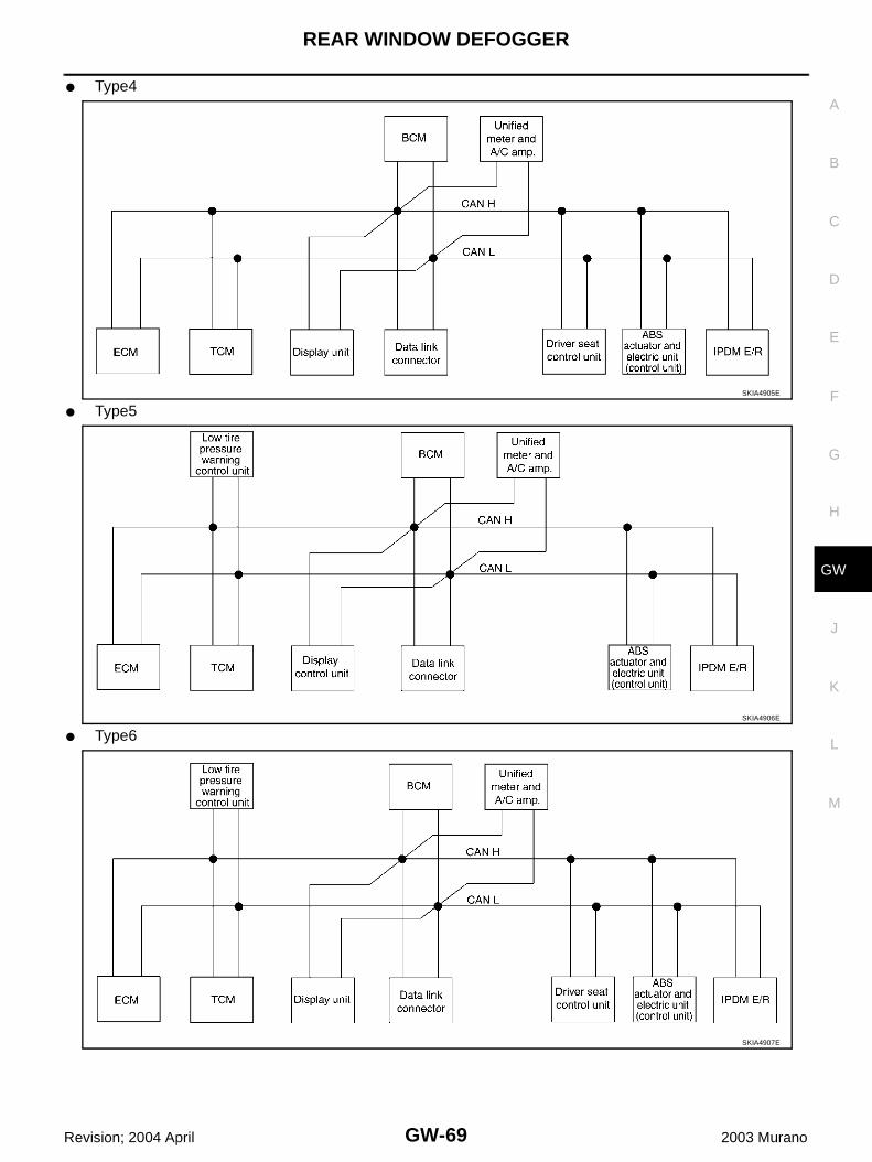
REAR WINDOW DEFOGGER
GW-69
C
D
E
F
G
H
J
K
L
M
A
B
GW
Revision; 2004 April 2003 Murano
● Type4
● Type5
● Type6
SKIA4905E
SKIA4906E
SKIA4907E

GW-70
REAR WINDOW DEFOGGER
Revision; 2004 April 2003 Murano
● Type7
● Type8SKIA4908E
SKIA4909E

REAR WINDOW DEFOGGER
GW-71
C
D
E
F
G
H
J
K
L
M
A
B
GW
Revision; 2004 April 2003 Murano
Input/output Signal ChartT: Transmit R: Receive
Signals ECM TCM
Low tire
pres-sure warn-
ing control
unit
Dis-play unit
Dis-play
control unit
BCM
Uni-fied
meter and A/C amp.
Driver seat
control unit
ABS actua-tor and elec-
tric unit (con-trol
unit)
IPDM E/R
Engine speed signal T R R R R
Engine status signal T R
Engine coolant temperature signal T R
CVT position indicator signal T R
Second position signal R T
Second position indicator signal T R
Engine and CVT integrated control signal
T R
R T
Accelerator pedal position signal T R
Closed throttle position signal T R
Wide open throttle position signal T R
Key switch signal T R
Ignition switch signal T R R
P range signal T R
Stop lamp switch signal R T
Fuel consumption monitor signal T R
CVT self-diagnosis signal R T
ABS operation signal R T
Air conditioner switch signal R T
A/C compressor request signal T R
A/C compressor feedback signal T R
Blower fan motor switch signal R T
A/C control signalT T R
R R T
Cooling fan speed request signal T R
Position lights request signal T R R
Low beam request signal T R
Low beam status signal R T
High beam request signal T R R
High beam status signal R T
Front fog lights request signal T R
Vehicle speed signalR R T
R R R R T R
Sleep request 1 signal T R
Sleep request 2 signal T R
Door switch signalR T
R R T R R R
Turn indicator signal T R

GW-72
REAR WINDOW DEFOGGER
Revision; 2004 April 2003 Murano
Key fob ID signal T R
Key fob door unlock signal T R
Seat belt buckle switch signal R T
Oil pressure switch signalR T
T R
Buzzer output signal T R
Fuel level sensor signal R T
Fuel level low warning signal R R T
Malfunction indicator lamp signal T R
ASCD SET lamp signal T R
ASCD CRUISE lamp signal T R
Input shaft revolution signal R T
Output shaft revolution signal R T
Front wiper request signal T R
Front wiper stop position signal R T
Rear window defogger switch signal T R
Rear window defogger control signal R R R T
Hood switch signal R T
Theft warning horn request signal T R
Horn chirp signal T R
Tire pressure signal T R
Tire pressure data signal T R R
ABS warning lamp signal R T
Brake warning lamp signal R T
System setting signal T T R
Parking brake switch signal R T
Signals ECM TCM
Low tire
pres-sure
warn-ing
control unit
Dis-play unit
Dis-play
control unit
BCM
Uni-fied
meter and A/C amp.
Driver seat
control unit
ABS actua-tor and elec-
tric unit (con-trol
unit)
IPDM E/R

REAR WINDOW DEFOGGER
GW-73
C
D
E
F
G
H
J
K
L
M
A
B
GW
Revision; 2004 April 2003 Murano
TYPE 9/TYPE10/TYPE 11/TYPE 12/TYPE 13/TYPE 14/TYPE 15/TYPE 16System Diagram● Type9
● Type10
● Type11
SKIA4910E
SKIA4911E
SKIA4912E

GW-74
REAR WINDOW DEFOGGER
Revision; 2004 April 2003 Murano
● Type12
● Type13
● Type14
SKIA4913E
SKIA4914E
SKIA4915E

REAR WINDOW DEFOGGER
GW-75
C
D
E
F
G
H
J
K
L
M
A
B
GW
Revision; 2004 April 2003 Murano
● Type15
● Type16SKIA4916E
SKIA4917E
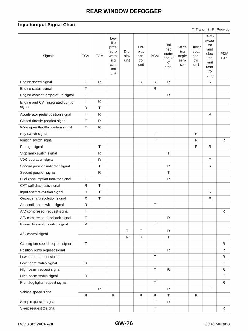
GW-76
REAR WINDOW DEFOGGER
Revision; 2004 April 2003 Murano
Input/output Signal ChartT: Transmit R: Receive
Signals ECM TCM
Low tire
pres-sure warn-
ing con-trol unit
Dis-play unit
Dis-play con-trol unit
BCM
Uni-fied
meter and A/
C amp.
Steer-ing
angle sen-sor
Driver seat con-trol unit
ABS actua-
tor and elec-tric unit
(con-trol
unit)
IPDM E/R
Engine speed signal T R R R R R
Engine status signal T R
Engine coolant temperature signal T R
Engine and CVT integrated control signal
T R
R T
Accelerator pedal position signal T R R
Closed throttle position signal T R
Wide open throttle position signal T R
Key switch signal T R
Ignition switch signal T R R
P range signal T R R
Stop lamp switch signal R T
VDC operation signal R T
Second position indicator signal T R R
Second position signal R T
Fuel consumption monitor signal T R
CVT self-diagnosis signal R T
Input shaft revolution signal R T R
Output shaft revolution signal R T R
Air conditioner switch signal R T
A/C compressor request signal T R
A/C compressor feedback signal T R
Blower fan motor switch signal R T
A/C control signalT T R
R R T
Cooling fan speed request signal T R
Position lights request signal T R R
Low beam request signal T R
Low beam status signal R T
High beam request signal T R R
High beam status signal R T
Front fog lights request signal T R
Vehicle speed signalR R T
R R R R T R
Sleep request 1 signal T R
Sleep request 2 signal T R

REAR WINDOW DEFOGGER
GW-77
C
D
E
F
G
H
J
K
L
M
A
B
GW
Revision; 2004 April 2003 Murano
Door switch signalR T
R R T R R R
Turn indicator signal T R
Key fob ID signal T R
Key fob door unlock signal T R
Seat belt buckle switch signal R T
Oil pressure switch signalR T
T R
Buzzer output signal T R
Fuel level sensor signal R T
Fuel level low warning signal R R T
Malfunction indicator signal T R
ASCD SET lamp signal T R
ASCD CRUISE lamp signal T R
Front wiper request signal T R
Front wiper stop position signal R T
Rear window defogger switch signal T R
Rear window defogger control signal R R R T
Hood switch signal R T
Theft warning horn request signal T R
Horn chirp signal T R
Steering angle sensor signal T R
Tire pressure signal T R
Tire pressure data signal T R R
CVT position indicator signal T R R
ABS warning lamp signal R T
VDC OFF indicator lamp signal R T
SLIP indicator lamp signal R T
Brake warning lamp signal R T
System setting signal T T R
Parking brake switch signal R T
Signals ECM TCM
Low tire
pres-sure
warn-ing
con-trol unit
Dis-play unit
Dis-play con-trol unit
BCM
Uni-fied
meter and A/
C amp.
Steer-ing
angle sen-sor
Driver seat con-trol unit
ABS actua-
tor and elec-tric unit
(con-trol unit)
IPDM E/R

GW-78
REAR WINDOW DEFOGGER
Revision; 2004 April 2003 Murano
CAN Communication Unit For AWD Models AIS003KP
×: Applicable
TYPE 17/TYPE 18/TYPE 19/TYPE 20/TYPE 21/TYPE 22/TYPE 23/TYPE 24System Diagram● Type17
Body type Wagon
Axle AWD
Engine VQ35DE
Transmission CVT
Brake control ABS VDC
Low tire pressure warning system
× × × × × × × ×
Navigation system × × × × × × × ×
Automatic drive positioner × × × × × × × ×
CAN communication unit
ECM × × × × × × × × × × × × × × × ×
TCM × × × × × × × × × × × × × × × ×
Low tire pressure warning control unit
× × × × × × × ×
Display unit × × × × × × × ×
Display control unit × × × × × × × ×
Data link connector × × × × × × × × × × × × × × × ×
BCM × × × × × × × × × × × × × × × ×
Unified meter and A/C amp. × × × × × × × × × × × × × × × ×
Steering angle sensor × × × × × × × ×
Driver seat control unit × × × × × × × ×
AWD control unit × × × × × × × × × × × × × × × ×
ABS actuator and electric unit (control unit)
× × × × × × × × × × × × × × × ×
IPDM E/R × × × × × × × × × × × × × × × ×
CAN communication typeGW-78, "TYPE 17/TYPE 18/TYPE 19/TYPE 20/
TYPE 21/TYPE 22/TYPE 23/TYPE 24"GW-84, "TYPE 25/TYPE26/TYPE 27/TYPE 28/
TYPE 29/TYPE 30/TYPE 31/TYPE 32"
SKIA4918E
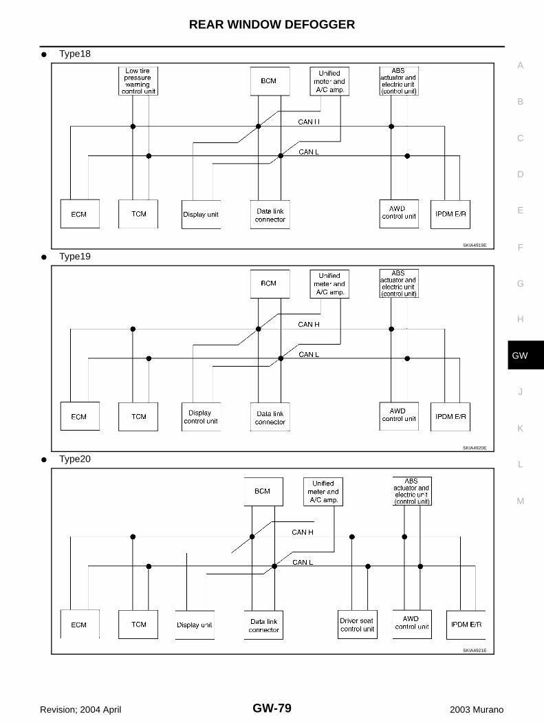
REAR WINDOW DEFOGGER
GW-79
C
D
E
F
G
H
J
K
L
M
A
B
GW
Revision; 2004 April 2003 Murano
● Type18
● Type19
● Type20
SKIA4919E
SKIA4920E
SKIA4921E

GW-80
REAR WINDOW DEFOGGER
Revision; 2004 April 2003 Murano
● Type21
● Type22
● Type23
SKIA4922E
SKIA4923E
SKIA4924E

REAR WINDOW DEFOGGER
GW-81
C
D
E
F
G
H
J
K
L
M
A
B
GW
Revision; 2004 April 2003 Murano
● Type24
SKIA4925E

GW-82
REAR WINDOW DEFOGGER
Revision; 2004 April 2003 Murano
Input/output Signal ChartT: Transmit R: Receive
Signals ECM TCM
Low tire
pres-sure warn-
ing con-trol unit
Dis-play unit
Dis-play con-trol unit
BCM
Uni-fied
meter and A/
C amp.
Driver seat con-trol unit
AWD con-trol unit
ABS actua-
tor and elec-tric unit
(con-trol unit)
IPDM E/R
CVT position indicator signal T R
Second position signal R T
Second position indicator signal T R
Engine speed signal T R R R R R R
Engine status signal T R
Engine coolant temperature signal T R
Accelerator pedal position signal T R R
Closed throttle position signal T R
Wide open throttle position signal T R
Key switch signal T R
Ignition switch signal T R R
P range signal T R
Stop lamp switch signal R T R
Fuel consumption monitor signal T R
CVT self-diagnosis signal R T
ABS operation signal R R T
Air conditioner switch signal R T
A/C compressor request signal T R
A/C compressor feedback signal T R
Blower fan motor switch signal R T
A/C control signalT T R
R R T
Cooling fan speed request signal T R
Position lights request signal T R R
Low beam request signal T R
Low beam status signal R T
High beam request signal T R R
High beam status signal R T
Front fog lights request signal T R
Vehicle speed signalR R R T
R R R R T R
Sleep request 1 signal T R
Sleep request 2 signal T R
Door switch signalR T
R R T R R R
Key fob ID signal T R
Key fob door unlock signal T R

REAR WINDOW DEFOGGER
GW-83
C
D
E
F
G
H
J
K
L
M
A
B
GW
Revision; 2004 April 2003 Murano
Turn indicator signal T R
Seat belt buckle switch signal R T
Oil pressure switch signalR T
T R
Buzzer output signal T R
Fuel level sensor signal R T
Fuel level low warning signal R R T
Malfunction indicator lamp signal T R
ASCD SET lamp signal T R
ASCD CRUISE lamp signal T R
Input shaft revolution signal R T
Output shaft revolution signal R T
Front wiper request signal T R
Front wiper stop position signal R T
Rear window defogger switch signal T R
Rear window defogger control signal R R R T
Engine and CVT integrated control signal
T R
R T
Hood switch signal R T
Theft warning horn request signal T R
Horn chirp signal T R
Tire pressure signal T R
Tire pressure data signal T R R
ABS warning lamp signal R T
Brake warning lamp signal R T
System setting signal T T R
AWD warning lamp signal R T
AWD lock indicator lamp signal R T
AWD lock switch signal T R
Parking brake switch signal R T R
Signals ECM TCM
Low tire
pres-sure
warn-ing
con-trol unit
Dis-play unit
Dis-play con-trol unit
BCM
Uni-fied
meter and A/
C amp.
Driver seat con-trol unit
AWD con-trol unit
ABS actua-
tor and elec-tric unit
(con-trol
unit)
IPDM E/R

GW-84
REAR WINDOW DEFOGGER
Revision; 2004 April 2003 Murano
TYPE 25/TYPE26/TYPE 27/TYPE 28/TYPE 29/TYPE 30/TYPE 31/TYPE 32System Diagram● Type25
● Type26
● Type27
SKIA4926E
SKIA4927E
SKIA4928E

REAR WINDOW DEFOGGER
GW-85
C
D
E
F
G
H
J
K
L
M
A
B
GW
Revision; 2004 April 2003 Murano
● Type28
● Type29
● Type30
SKIA4929E
SKIA4930E
SKIA4931E

GW-86
REAR WINDOW DEFOGGER
Revision; 2004 April 2003 Murano
● Type31
● Type32SKIA4932E
SKIA4933E
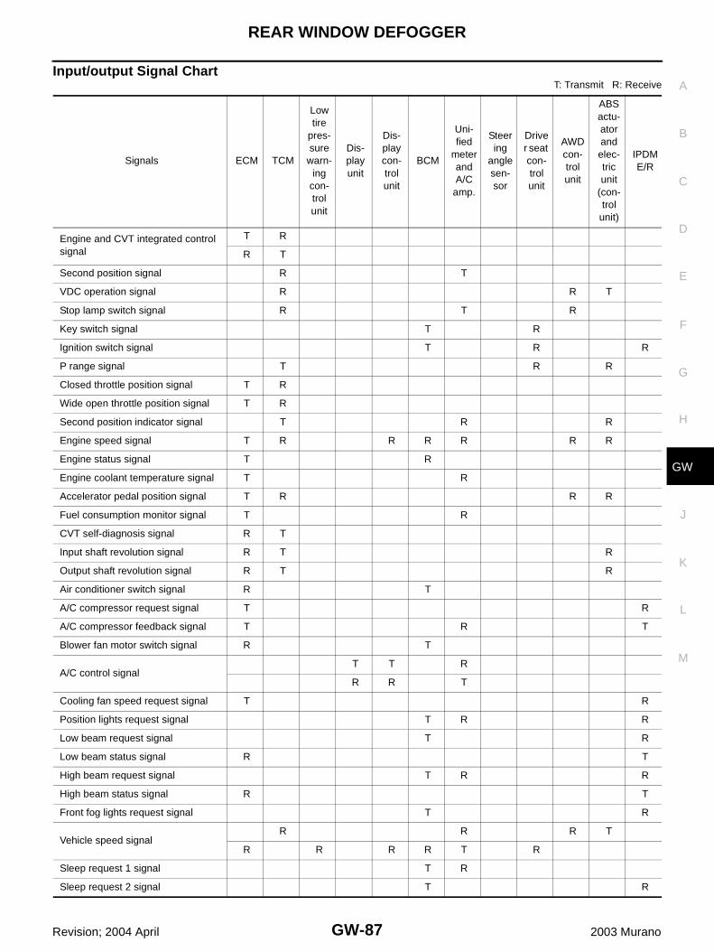
REAR WINDOW DEFOGGER
GW-87
C
D
E
F
G
H
J
K
L
M
A
B
GW
Revision; 2004 April 2003 Murano
Input/output Signal ChartT: Transmit R: Receive
Signals ECM TCM
Low tire
pres-sure
warn-ing
con-trol unit
Dis-play unit
Dis-play con-trol unit
BCM
Uni-fied
meter and A/C
amp.
Steering
angle sen-sor
Driver seat con-trol unit
AWD con-trol unit
ABS actu-ator and elec-tric unit
(con-trol
unit)
IPDM E/R
Engine and CVT integrated control signal
T R
R T
Second position signal R T
VDC operation signal R R T
Stop lamp switch signal R T R
Key switch signal T R
Ignition switch signal T R R
P range signal T R R
Closed throttle position signal T R
Wide open throttle position signal T R
Second position indicator signal T R R
Engine speed signal T R R R R R R
Engine status signal T R
Engine coolant temperature signal T R
Accelerator pedal position signal T R R R
Fuel consumption monitor signal T R
CVT self-diagnosis signal R T
Input shaft revolution signal R T R
Output shaft revolution signal R T R
Air conditioner switch signal R T
A/C compressor request signal T R
A/C compressor feedback signal T R T
Blower fan motor switch signal R T
A/C control signalT T R
R R T
Cooling fan speed request signal T R
Position lights request signal T R R
Low beam request signal T R
Low beam status signal R T
High beam request signal T R R
High beam status signal R T
Front fog lights request signal T R
Vehicle speed signalR R R T
R R R R T R
Sleep request 1 signal T R
Sleep request 2 signal T R

GW-88
REAR WINDOW DEFOGGER
Revision; 2004 April 2003 Murano
Door switch signalR T
R R T R R R
Turn indicator signal T R
Key fob ID signal T R
Key fob door unlock signal T R
Seat belt buckle switch signal R T
Oil pressure switch signalR T
T R
Buzzer output signal T R
Fuel level sensor signal R T
Fuel level low warning signal R R T
Malfunction indicator signal T R
ASCD SET lamp signal T R
ASCD CRUISE lamp signal T R
Front wiper request signal T R
Front wiper stop position signal R T
Rear window defogger switch signal T R
Rear window defogger control signal R R R T
Hood switch signal R T
Theft warning horn request signal T R
Horn chirp signal T R
Steering angle sensor signal T R
Tire pressure signal T R
Tire pressure data signal T R R
CVT position indicator signal T R R
ABS warning lamp signal R T
VDC OFF indicator lamp signal R T
SLIP indicator lamp signal R T
Brake warning lamp signal R T
System setting signal T T R
AWD warning lamp signal R T
AWD lock indicator lamp signal R T
AWD lock switch signal T R
Parking brake switch signal R T R
Signals ECM TCM
Low tire
pres-sure warn-
ing con-trol unit
Dis-play unit
Dis-play con-trol unit
BCM
Uni-fied
meter and A/C
amp.
Steering
angle sen-sor
Driver seat con-trol unit
AWD con-trol unit
ABS actu-ator and elec-tric unit
(con-trol unit)
IPDM E/R

REAR WINDOW DEFOGGER
GW-89
C
D
E
F
G
H
J
K
L
M
A
B
GW
Revision; 2004 April 2003 Murano
Schematic – DEF – AIS002IE
TIWA0292E

GW-90
REAR WINDOW DEFOGGER
Revision; 2004 April 2003 Murano
Wiring Diagram –DEF– AIS002IF
TIWA0293E

REAR WINDOW DEFOGGER
GW-91
C
D
E
F
G
H
J
K
L
M
A
B
GW
Revision; 2004 April 2003 Murano
TIWA0294E
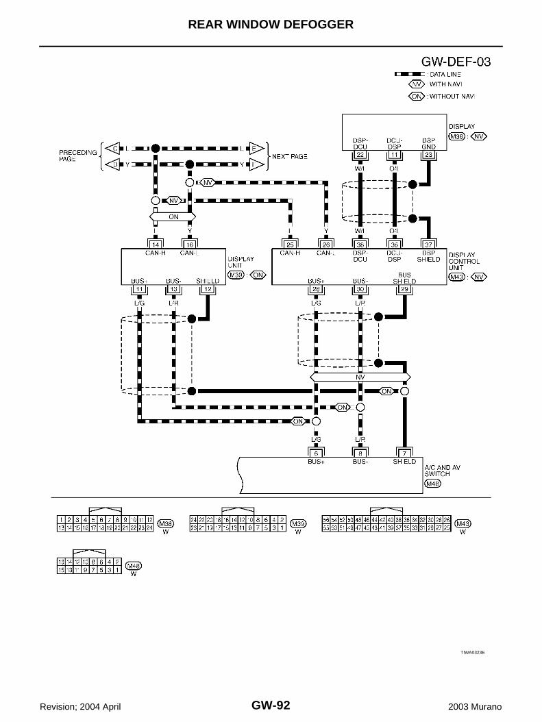
GW-92
REAR WINDOW DEFOGGER
Revision; 2004 April 2003 Murano
TIWA0323E
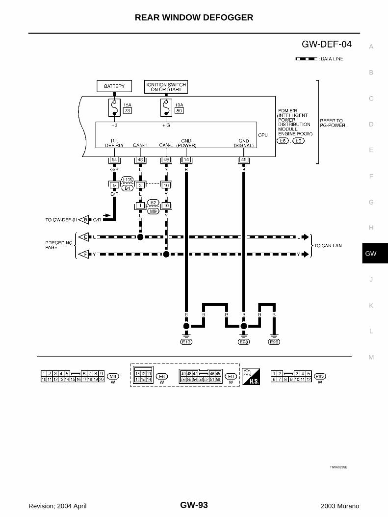
REAR WINDOW DEFOGGER
GW-93
C
D
E
F
G
H
J
K
L
M
A
B
GW
Revision; 2004 April 2003 Murano
TIWA0295E

GW-94
REAR WINDOW DEFOGGER
Revision; 2004 April 2003 Murano
Terminal and Reference Value for BCM AIS002IG
Terminal and Reference Value for IPDM E/R AIS002IH
Work Flow AIS002II
1. Check the symptom and customer's requests.2. Understand the outline of system. Refer to GW-65, "System Description" .3. According to the trouble diagnosis chart, repair or replace the cause of the malfunction. Refer to GW-97,
"Trouble Diagnoses Symptom Chart" .4. Does rear window defogger operate normally? YES: GO TO 5, NO: GO TO 3.5. INSPECTION END.
Terminal Wire color Item ConditionVoltage (V)(Approx.)
7 W/B Battery power supply — Battery voltage
8 B Ground — 0
35 R Ignition switch ON or START Ignition switch (ON or START position) Battery voltage
69 G/WRear window defogger switch signal
When rear window defogger switch is pressed. 0
When rear window defogger switch is OFF. 5
70 L CAN H — —
71 Y CAN L — —
72 O K-Line — —
Terminal Wire color Item ConditionVoltage (V)(Approx.)
3 L Battery power supply — Battery voltage
8 W Battery power supply — Battery voltage
14 B Ground (Power) — 0
45 B Ground (Signal) — 0
48 L CAN H — —
49 Y CAN L — —
54 G/RRear window defogger relay control signal
When rear window defogger switch is ON. 0
When rear window defogger switch is OFF. Battery voltage

REAR WINDOW DEFOGGER
GW-95
C
D
E
F
G
H
J
K
L
M
A
B
GW
Revision; 2004 April 2003 Murano
CONSULT-II Inspection Procedure AIS003KV
CAUTION:If CONSULT-II is used with no connection of CONSULT-II CONVERTER, malfunctions might bedetected in self-diagnosis depending on control unit which carry out CAN communication. 1. Turn ignition switch “OFF”.2. Connect “CONSULT-II” and CONSULT-II CONVERTER to data
link connector.
3. Turn ignition switch “ON”.4. Touch “START (NISSAN BASED VHCL)”.
5. Touch “BCM”.If “BCM” is not indicated, go to GI-38 , “CONSULT-II Date LinkConnector (DLC) Circuit”
6. Touch “REAR DEFOGGER”.
PIIA1095E
MBIB0233E
LIIA0033E
LIIA0153E

GW-96
REAR WINDOW DEFOGGER
Revision; 2004 April 2003 Murano
7. Select diagnosis mode,“DATA MONITOR” and “ACTIVE TEST”.
DATA MONITORDisplay Item List
ACTIVE TESTDisplay Item List
SEL322W
Monitor item “Operation” Content
REAR DEF SW “ON/OFF”Displays “Press (ON)/others (OFF)” status determined with the rear window defogger switch.
IGN ON SW “ON/OFF” Displays “IGN (ON)/OFF” status determined with the ignition switch signal.
Test item Content
REAR DEFOGGER Gives a drive signal to the rear window defogger relay to activate it.

REAR WINDOW DEFOGGER
GW-97
C
D
E
F
G
H
J
K
L
M
A
B
GW
Revision; 2004 April 2003 Murano
Trouble Diagnoses Symptom Chart AIS002IK
Make sure other systems using the signal of the following systems operate normally.
Symptom Diagnoses / Service procedure Refer to page
Rear window defogger and door mirror defogger do not operate. (With door mirror defogger)
1. BCM power supply and ground circuit check GW-98
2. IPDM E/R auto active test check PG-41
3. Rear window defogger switch circuit check GW-99
4. Rear window defogger power supply circuit check GW-100
5. Replace IPDM E/ R PG-46
Rear window defogger does not operate. (Without door mirror defogger)
1. BCM power supply and ground circuit check GW-98
2. IPDM E/R auto active test check PG-41
3. Rear window defogger switch circuit check GW-99
4. Rear window defogger power supply circuit check GW-100
5. Rear window defogger circuit check GW-102
6. Filament check GW-108
7. Replace IPDM E/ R PG-46
Rear window defogger does not operate but both of door mirror defogger operate.(With door mirror defogger)
1. Rear window defogger circuit check GW-102
2. Filament check GW-108
Door mirror defogger does not operated but both of rear window defogger operate. (With door mirror defogger)
1. Door mirror defogger power supply circuit check GW-103
Driver side door mirror defogger does not operate. 1. Driver side door mirror defogger circuit check GW-105
Passenger side door mirror defogger does not operate. 1. Passenger side door mirror defogger circuit check GW-106
Rear window defogger switch does not light, and rear win-dow defogger is not displayed on the display. But rear window defogger operates.
1. Rear window defogger signal check GW-107

GW-98
REAR WINDOW DEFOGGER
Revision; 2004 April 2003 Murano
BCM Power Supply and Ground Circuit Check AIS0034Z
1. CHECK FUSE
● Check 10A fuse [No.1, located in fuse block (J/B)]● Check 50A fusible link (letter F located in the fuse and fusible link box)NOTE:Refer to GW-65, "Component Parts and Harness Connector Location" .OK or NGOK >> GO TO 2.NG >> If fuse is blown, be sure to eliminate cause of malfunction before installing new fuse. Refer to PG-
3, "POWER SUPPLY ROUTING CIRCUIT"
2. CHECK POWER SUPPLY CIRCUIT
1. Turn ignition switch ON.2. Check voltage between BCM connector M35, E118 terminal 7, 35 and ground.
OK or NGOK >> GO TO 3.NG >> Check BCM power supply circuit for open or short.
3. CHECK GROUND CIRCUIT
1. Turn ignition switch OFF.2. Disconnect BCM connector.3. Check continuity between BCM connector E118 terminal 8 and ground.
OK or NGOK >> BCM power supply and ground circuit is OK.NG >> Check BCM ground circuit for open or short.
7 (W/B) – Ground :Battery voltage35 (R) – Ground :Battery voltage
PIIA3010E
8 (B) – Ground : Continuity should exist.
PIIA1127E
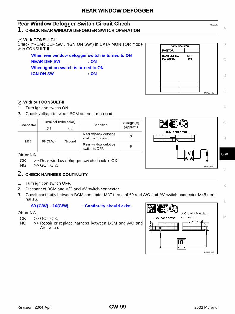
REAR WINDOW DEFOGGER
GW-99
C
D
E
F
G
H
J
K
L
M
A
B
GW
Revision; 2004 April 2003 Murano
Rear Window Defogger Switch Circuit Check AIS002IL
1. CHECK REAR WINDOW DEFOGGER SWITCH OPERATION
With CONSULT-IICheck (“REAR DEF SW”, “IGN ON SW”) in DATA MONITOR modewith CONSULT-II.
With out CONSULT-II1. Turn ignition switch ON.2. Check voltage between BCM connector ground.
OK or NGOK >> Rear window defogger switch check is OK.NG >> GO TO 2.
2. CHECK HARNESS CONTINUITY
1. Turn ignition switch OFF.2. Disconnect BCM and A/C and AV switch connector.3. Check continuity between BCM connector M37 terminal 69 and A/C and AV switch connector M48 termi-
nal 16.
OK or NGOK >> GO TO 3.NG >> Repair or replace harness between BCM and A/C and
AV switch.
When rear window defogger switch is turned to ONREAR DEF SW : ONWhen ignition switch is turned to ONIGN ON SW : ON
PIIA2373E
ConnectorTerminal (Wire color)
ConditionVoltage (V)(Approx.)(+) (–)
M37 69 (G/W) Ground
Rear window defogger switch is pressed.
0
Rear window defogger switch is OFF.
5
PIIA3860E
69 (G/W) – 16(G/W) : Continuity should exist.
PIIA4226E

GW-100
REAR WINDOW DEFOGGER
Revision; 2004 April 2003 Murano
3. CHECK BCM OUTPUT SIGNAL
1. Connect BCM connector.2. Turn ignition switch ON.3. Check voltage between BCM connector M37 terminal 69 and
ground.
OK or NGOK >> Replace A/C and AV switch.NG >> Replace BCM.
Rear Window Defogger Power Supply Circuit Check AIS002IM
1. CHECK FUSE
● Check 10A fuse [No.12, located in the fuse block (J/B)]● Check 20A fuse (No.77, located in the IPDM E/R)● Check 20A fuse (No.78, located in the IPDM E/R)NOTE:Refer to GW-65, "Component Parts and Harness Connector Location" .OK or NGOK >> GO TO 2.NG >> If fuse is blown, be sure to eliminate cause of malfunction before installing new fuse, refer to PG-
3, "POWER SUPPLY ROUTING CIRCUIT" .
2. CHECK POWER SUPPLY CIRCUIT
1. Turn ignition switch OFF.2. Disconnect rear window defogger relay.3. Turn ignition switch ON.4. Check voltage between rear window defogger relay connector and ground.
OK or NGOK >> GO TO 3.NG >> Repair or replace harness between fuse block (J/B) and
rear window defogger relay.
69 (G/W) – Ground : Approx. 5
PIIA3860E
ConnectorTerminals (Wire color) Voltage (V)
(Approx.)(+) (-)
B8
1 (G)
Ground Battery voltage3 (L)
6 (W)
PIIA4233E
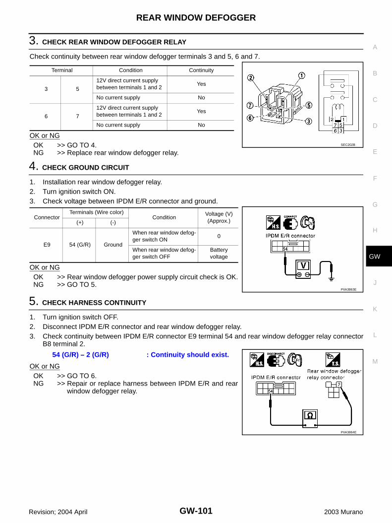
REAR WINDOW DEFOGGER
GW-101
C
D
E
F
G
H
J
K
L
M
A
B
GW
Revision; 2004 April 2003 Murano
3. CHECK REAR WINDOW DEFOGGER RELAY
Check continuity between rear window defogger terminals 3 and 5, 6 and 7.
OK or NGOK >> GO TO 4.NG >> Replace rear window defogger relay.
4. CHECK GROUND CIRCUIT
1. Installation rear window defogger relay.2. Turn ignition switch ON.3. Check voltage between IPDM E/R connector and ground.
OK or NGOK >> Rear window defogger power supply circuit check is OK.NG >> GO TO 5.
5. CHECK HARNESS CONTINUITY
1. Turn ignition switch OFF.2. Disconnect IPDM E/R connector and rear window defogger relay.3. Check continuity between IPDM E/R connector E9 terminal 54 and rear window defogger relay connector
B8 terminal 2.
OK or NGOK >> GO TO 6.NG >> Repair or replace harness between IPDM E/R and rear
window defogger relay.
Terminal Condition Continuity
3 5
12V direct current supply between terminals 1 and 2
Yes
No current supply No
6 7
12V direct current supply between terminals 1 and 2
Yes
No current supply No
SEC202B
ConnectorTerminals (Wire color)
ConditionVoltage (V)(Approx.)(+) (-)
E9 54 (G/R) Ground
When rear window defog-ger switch ON
0
When rear window defog-ger switch OFF
Battery voltage
PIIA3863E
54 (G/R) – 2 (G/R) : Continuity should exist.
PIIA3864E
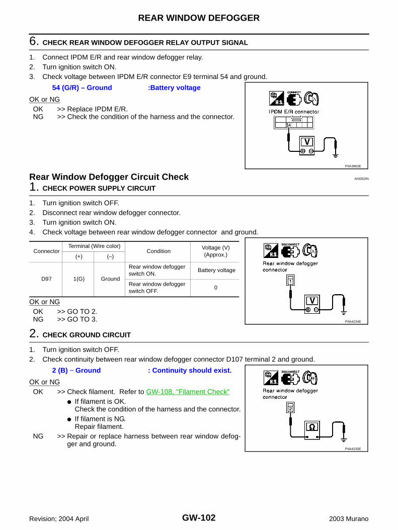
GW-102
REAR WINDOW DEFOGGER
Revision; 2004 April 2003 Murano
6. CHECK REAR WINDOW DEFOGGER RELAY OUTPUT SIGNAL
1. Connect IPDM E/R and rear window defogger relay.2. Turn ignition switch ON.3. Check voltage between IPDM E/R connector E9 terminal 54 and ground.
OK or NGOK >> Replace IPDM E/R.NG >> Check the condition of the harness and the connector.
Rear Window Defogger Circuit Check AIS002IN
1. CHECK POWER SUPPLY CIRCUIT
1. Turn ignition switch OFF.2. Disconnect rear window defogger connector.3. Turn ignition switch ON.4. Check voltage between rear window defogger connector and ground.
OK or NGOK >> GO TO 2.NG >> GO TO 3.
2. CHECK GROUND CIRCUIT
1. Turn ignition switch OFF.2. Check continuity between rear window defogger connector D107 terminal 2 and ground.
OK or NGOK >> Check filament. Refer to GW-108, "Filament Check"
● If filament is OK.Check the condition of the harness and the connector.
● If filament is NG.Repair filament.
NG >> Repair or replace harness between rear window defog-ger and ground.
54 (G/R) – Ground :Battery voltage
PIIA3863E
ConnectorTerminal (Wire color)
ConditionVoltage (V)(Approx.)(+) (–)
D97 1(G) Ground
Rear window defogger switch ON.
Battery voltage
Rear window defogger switch OFF.
0
PIIA4234E
2 (B) − Ground : Continuity should exist.
PIIA4235E

REAR WINDOW DEFOGGER
GW-103
C
D
E
F
G
H
J
K
L
M
A
B
GW
Revision; 2004 April 2003 Murano
3. CHECK HARNESS CONTINUITY
1. Turn ignition switch OFF.2. Disconnect rear window defogger relay.3. Check continuity between rear window defogger relay connector B8 terminal 5 and rear window defogger
connector D97 terminal 1.
OK or NGOK >> Check the condition of the harness and the connector.NG >> Repair or replace harness rear window defogger relay
and rear window defogger. When there is malfunctioninside back door, replace the back door.
Door Mirror Defogger Power Supply Circuit Check AIS002IO
1. CHECK FUSE
● Check 10A fuse [No.8, located in the fuse block (J/B)]NOTE:Refer to GW-65, "Component Parts and Harness Connector Location" .OK or NGOK >> GO TO 2.NG >> If fuse is blown, be sure to eliminate cause of malfunction before installing new fuse. Refer to PG-
3, "POWER SUPPLY ROUTING CIRCUIT" .
2. CHECK POWER SUPPLY CIRCUIT 1
1. Turn ignition switch ON.2. Check voltage between fuse block (J/B) connector and ground.
OK or NGOK >> GO TO 3.NG >> Repair or replace harness between rear window defogger relay and fuse block (J/B).
5 (G) – 1 (G) : Continuity should exist.
PIIA4236E
ConnectorTerminal (Wire color)
ConditionVoltage (V)(Approx.)(+) (–)
E101 2C (G) Ground
Rear window defogger switch ON
Battery voltage
Rear window defogger switch OFF
0
PIIA2388E

GW-104
REAR WINDOW DEFOGGER
Revision; 2004 April 2003 Murano
3. CHECK POWER SUPPLY CIRCUIT 2
Check voltage between fuse block (J/B) connector and ground.
OK or NGOK >> GO TO 4. NG >> Replace fuse block (J/B).
4. CHECK HARNESS CONTINUITY
1. Turn ignition switch OFF.2. Disconnect fuse block (J/B) and door mirror connector.3. Check continuity between fuse block (J/B) connector M5 terminal 5B and door mirror connector D2 (driver
side) or D32 (passenger side) terminal 1.
OK or NGOK >> GO TO 5.NG >> Repair or replace harness between fuse block (J/B) and
malfunction door mirror connector.
5. CHECK GROUND CIRCUIT
Check continuity between each door mirror connector D2 (driver side), D32 (passenger side) terminal 5 andground.
OK or NGOK >> GO TO 6.NG >> Repair or replace harness.
ConnectorTerminal (Wire color)
ConditionVoltage (V)(Approx.)(+) (–)
M5 5B (L) Ground
Rear window defogger switch ON
Battery voltage
Rear window defogger switch OFF
0
PIIA2386E
5B (B) – 1 (B) : Continuity should exist.
PIIA4228E
5 (B) – Ground : Continuity should exist.
PIIA4229E

REAR WINDOW DEFOGGER
GW-105
C
D
E
F
G
H
J
K
L
M
A
B
GW
Revision; 2004 April 2003 Murano
6. CHECK DOOR MIRROR DEFOGGER
1. Connector door mirror connector.2. Check continuity between each door mirror connector D2 (driver side), D32 (passenger side) terminals 1
and 5.
OK or NGOK >> Check the condition of the harness and the connector.NG >> Replace malfunctioning door mirror.
Driver Side Door Mirror Defogger Circuit Check AIS002IP
1. CHECK POWER SUPPLY CIRCUIT
1. Turn ignition switch OFF.2. Disconnect door mirror (driver side) connector. 3. Turn ignition switch ON.4. Check voltage between door mirror (driver side) connector and ground.
OK or NGOK >> GO TO 2.NG >> Repair or replace harness between fuse block (J/B) and
door mirror (driver side).
2. CHECK GROUND CIRCUIT
1. Turn ignition switch OFF.2. Check continuity between door mirror (driver side) connector D2
terminal 5 and ground.
OK or NGOK >> GO TO 3.NG >> Repair or replace harness between door mirror (driver
side) and ground.
1 (L/B) – 5 (L/B) : Continuity should exist.
PIIA4230E
ConnectorTerminal (Wire color)
ConditionVoltage (V)(Approx.)(+) (–)
D2 1 (L/B) Ground
Rear window defogger switch ON
Battery voltage
Rear window defogger switch OFF
0
PIIA4231E
5 (B) – Ground : Continuity should exist.
PIIA4229E

GW-106
REAR WINDOW DEFOGGER
Revision; 2004 April 2003 Murano
3. CHECK DOOR MIRROR DEFOGGER
1. Connector door mirror connector.2. Check continuity between each door mirror connector D2 (driver side) terminals 1 and 5.
OK or NGOK >> Check the condition of the harness and the connector.NG >> Replace door mirror (driver side).
Passenger Side Door Mirror Defogger Circuit Check AIS002IQ
1. CHECK POWER SUPPLY CIRCUIT
1. Turn ignition switch OFF.2. Disconnect door mirror (passenger side) connector.3. Turn ignition switch ON.4. Check voltage between door mirror (passenger side) connector and ground.
OK or NGOK >> GO TO 2.NG >> Repair or replace harness between fuse block (J/B) and
door mirror (passenger side).
2. CHECK GROUND CIRCUIT
1. Turn ignition switch OFF.2. Check continuity between door mirror (passenger side) connector D32 terminal 5 and ground.
OK or NGOK >> GO TO 3.NG >> Repair or replace harness between door mirror (passen-
ger side) and ground.
1 (L/B) – 5 (L/B) : Continuity should exist.
PIIA4230E
ConnectorTerminal (Wire color)
ConditionVoltage (V)(Approx.)(+) (–)
D32 1 (L/B) Ground
Rear window defogger switch ON
Battery voltage
Rear window defogger switch OFF
0
PIIA4231E
5 (B) – Ground : Continuity should exist.
PIIA4229E

REAR WINDOW DEFOGGER
GW-107
C
D
E
F
G
H
J
K
L
M
A
B
GW
Revision; 2004 April 2003 Murano
3. CHECK DOOR MIRROR DEFOGGER
1. Connector door mirror connector.2. Check continuity between each door mirror connector D32 (passenger side) terminals 1 and 5.
OK or NGOK >> Check the condition of the harness and the connector.NG >> Replace door mirror (passenger side).
Rear Window Defogger Signal Check AIS002J2
1. CHECK REAR WINDOW DEFOGGER SWITCH LAMP
A/C and AV switch self-diagnosis is executed. Refer to AV-102, "A/C and AV Switch Self-Diagnosis Function"
OK or NGOK >> GO TO 2.NG >> Replace A/C and AV switch.
2. CHECK AV COMMUNICATION LINE
AV communication line check is executed. Refer to AV-109, "AV Communication Line Check"
OK or NGOK >> GO TO 3.NG >> Replace display control unit.
3. CHECK CAN COMMUNICATION LINE
CAN communication line check is executed. Refer to AV-110, "CAN Communication Line Check"OK or NGOK >> Check the condition of the harness and the connector.NG >> In addition, it is necessary to check CAN communication line. Refer to AV-110, "CAN Communica-
tion Line Check"
1 (L/B) – 5 (L/B) : Continuity should exist.
PIIA4230E
Does rear window defogger switch light?
Is rear window defogger displayed on the display?

GW-108
REAR WINDOW DEFOGGER
Revision; 2004 April 2003 Murano
Filament Check AIS002IR
1. When measuring voltage, wrap tin foil around the top of the neg-ative probe. Then press the foil against the wire with your finger.
2. Attach probe circuit tester (in Volt range) to middle portion ofeach filament.
3. If a filament is burned out, circuit tester registers 0 or batteryvoltage.
4. To locate burned out point, move probe to left and right along fil-ament. Test needle will swing abruptly when probe passes thepoint.
Filament Repair AIS002IS
REPAIR EQUIPMENT● Conductive silver composition (Dupont No. 4817 or equivalent)● Ruler 30 cm (11.8 in) long● Drawing pen● Heat gun● Alcohol● Cloth
SEL122R
SEL263
SEL265
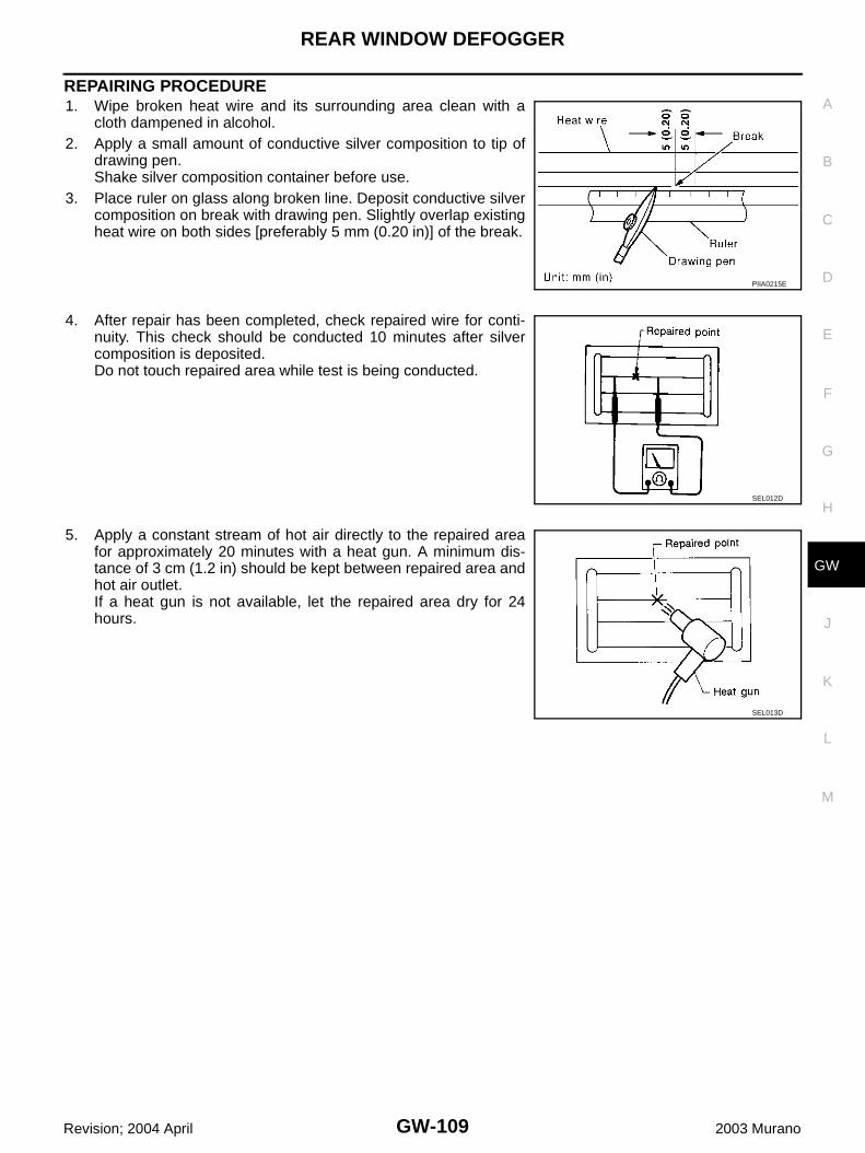
REAR WINDOW DEFOGGER
GW-109
C
D
E
F
G
H
J
K
L
M
A
B
GW
Revision; 2004 April 2003 Murano
REPAIRING PROCEDURE1. Wipe broken heat wire and its surrounding area clean with a
cloth dampened in alcohol.2. Apply a small amount of conductive silver composition to tip of
drawing pen.Shake silver composition container before use.
3. Place ruler on glass along broken line. Deposit conductive silvercomposition on break with drawing pen. Slightly overlap existingheat wire on both sides [preferably 5 mm (0.20 in)] of the break.
4. After repair has been completed, check repaired wire for conti-nuity. This check should be conducted 10 minutes after silvercomposition is deposited.Do not touch repaired area while test is being conducted.
5. Apply a constant stream of hot air directly to the repaired areafor approximately 20 minutes with a heat gun. A minimum dis-tance of 3 cm (1.2 in) should be kept between repaired area andhot air outlet.If a heat gun is not available, let the repaired area dry for 24hours.
PIIA0215E
SEL012D
SEL013D

GW-110
DOOR MIRROR
Revision; 2004 April 2003 Murano
DOOR MIRROR PFP:96301
Automatic Drive Positioner Interlocking Door Mirror AIS003I3
Automatic drive positioner interlocking door mirror. Refer to SE-12, "AUTOMATIC DRIVE POSITIONER" .

DOOR MIRROR
GW-111
C
D
E
F
G
H
J
K
L
M
A
B
GW
Revision; 2004 April 2003 Murano
Power Door Mirror (Only Manual Operation Model) AIS001T2
WIRING DIAGRAM –MIRROR–
TIWA0296E

GW-112
DOOR MIRROR
Revision; 2004 April 2003 Murano
Removal and Installation AIS005AO
CAUTION:Be careful not to damage the mirror bodies.
REMOVAL1. Remove the front door finisher. Refer to EI-30, "DOOR FINISHER" .2. Remove the front door sash cover.3. Remove the door mirror harness connector.4. Remove the door mirror mounting nuts, and remove the door mirror assembly.
INSTALLATIONInstall in the reverse order of removal.
Disassembly and Assembly AIS005AP
DISASSEMBLY1. Place the mirror body with mirror glass facing upward.2. Put a strip of protective tape on mirror body.3. As shown in the figure insert a small slotted screwdriver into the
recess between mirror base (mirror holder) and mirror holderbracket and push up two pawls to remove mirror holder lowerhalf side. NOTE:When pushing up pawls do not attempt to use one recess only,be sure to push up with both recesses.Insert screwdriver into recesses, and push up while rotating(twist) to make work easier.
4. Remove two terminals of mirror heater attachment.5. Lightly lift up lower side of mirror surface from mirror surface, and detach two pawls of upper side as if
pulling it out. Remove mirror surface from mirror body.
1. Door mirror assembly 2. Front door sash cover
PIIA4001E
PIIA4002E
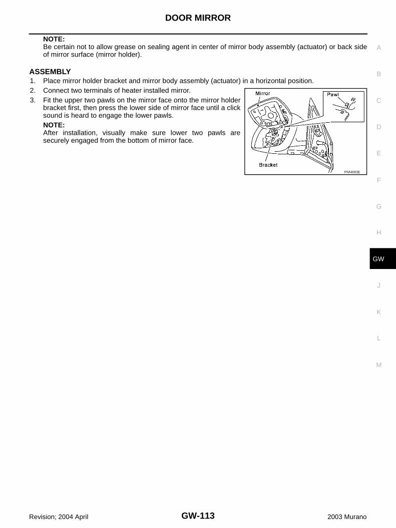
DOOR MIRROR
GW-113
C
D
E
F
G
H
J
K
L
M
A
B
GW
Revision; 2004 April 2003 Murano
NOTE:Be certain not to allow grease on sealing agent in center of mirror body assembly (actuator) or back sideof mirror surface (mirror holder).
ASSEMBLY1. Place mirror holder bracket and mirror body assembly (actuator) in a horizontal position.2. Connect two terminals of heater installed mirror.3. Fit the upper two pawls on the mirror face onto the mirror holder
bracket first, then press the lower side of mirror face until a clicksound is heard to engage the lower pawls.NOTE:After installation, visually make sure lower two pawls aresecurely engaged from the bottom of mirror face.
PIIA4003E
GW-114
DOOR MIRROR
Revision; 2004 April 2003 Murano