glass quality standards manual
DESCRIPTION
how to control your Glass ProductonTRANSCRIPT

QUALITY STANDARDS MANUALContents1. Definitions____________________________________________________________________91.1 Glass Types...........................................................................................................................................91.1.1 Annealed Glass..................................................................................................................................................91.1.2 Tinted Glass........................................................................................................................................................91.1.3 Coated Float Glass.............................................................................................................................................91.1.4 Self Cleaning Glass............................................................................................................................................91.1.5 Anti Reflective Glass..........................................................................................................................................91.1.6 Extra Clear Glass................................................................................................................................................91.1.7 Toughened/Tempered Glass...............................................................................................................................91.1.8 Heat Strengthened Glass...................................................................................................................................91.1.9 Heat Soaked Glass.............................................................................................................................................91.1.10 Laminated Glass............................................................................................................................................101.1.11 Insulated glass................................................................................................................................................101.1.12 Sandblasted Glass.........................................................................................................................................101.1.13 Etched Glass..................................................................................................................................................101.1.14 Lacquered Glass............................................................................................................................................101.1.15 Ceramic Glass................................................................................................................................................10
2. Float Glass___________________________________________________________________112.1 Manufacturing Process........................................................................................................................112.2 Quality Parameters...............................................................................................................................112.2.1 Thickness

.......................................................................................................................................................
..112.2.2 Dimensions.......................................................................................................................................................112.2.3 Diagonals..........................................................................................................................................................112.2.4 Glass Edge Finish.............................................................................................................................................112.2.5 Warpage and Bow............................................................................................................................................122.2.6 Surface and Body Defects...............................................................................................................................122.2.6.1 Scratches..........................................................................................................................................................................122.2.6.2 Bubbles / Spots / Stones..................................................................................................................................................12
3. Coated Glass__________________________________________________________________133.1 Basic Definitions..................................................................................................................................133.1.1 Coated Glass....................................................................................................................................................133.1.2 Coating.............................................................................................................................................................133.1.3 On-Line Coating...............................................................................................................................................133.1.4 Off-line Coating................................................................................................................................................133.1.5 Additive Methods of Deposition........................................................................................................................133.2 Definitions of Appearance Defects.......................................................................................................133.2.1 Uniformity Defect..............................................................................................................................................133.2.2 Stain..................................................................................................................................................................133.2.3 Punctual Defect................................................................................................................................................13Quality Standards Manual FQSM G-101:2012!Federation of Safety Glass (All Rights Reserved)! 43.2.3.1 Spot...................................................................................................................................................................................133.2.3.2 Pinhole..............................................................................................................................................................................133.2.3.3 Scratch..............................................................................................................................................................................133.3 Appearance..........................................................................................................................................133.3.1 General.............................................................................................................................................................13

3.3.2 Detection of Defects.........................................................................................................................................133.3.3 Conditions of Examination................................................................................................................................133.3.3.1 General..............................................................................................................................................................................133.3.3.2 Uniformity Defects and Stains..........................................................................................................................................143.3.3.3 Punctual Defects...............................................................................................................................................................143.3.4 Acceptance Criteria of Coated Glass Defects...................................................................................................14
4. Toughened / Tempered Glass_____________________________________________________154.1 Manufacturing Process........................................................................................................................154.2 Quality Parameters...............................................................................................................................154.2.1 Thickness.........................................................................................................................................................154.2.2 Dimensions and Squareness.............................................................................................................................154.2.3 Holes and Cutouts............................................................................................................................................154.2.3.1 Hole Dimensions...............................................................................................................................................................154.2.3.2 Hole and Cutout Location.................................................................................................................................................154.2.4 Glass Edge Finish.............................................................................................................................................154.2.5 Flatness............................................................................................................................................................154.2.5.1 General Information...........................................................................................................................................................154.2.5.2 Measurement of Overall Bow............................................................................................................................................164.2.5.3 Warpage and Bow Tolerances..........................................................................................................................................164.2.5.3.1 Overall Bow Tolerances................................................................................................................................................164.2.5.3.2 Local Bow Tolerances..................................................................................................................................................164.2.5.4 Important Considerations for Optical Distortion in Fully Toughened Glass.......................................................................174.2.6 Appearance......................................................................................................................................................174.2.7 Fragmentation Test...........................................................................................................................................174.2.7.1 General..............................................................................................................................................................................174.2.7.2 Test Procedure..................................................................................................................................................................174.2.7.3 Assessment of Fragmentation..........................................................................................................................................174.2.7.4 Minimum Values from the Particle Count...........................................................................................................................184.2.8 Stress Measurement Test.................................................................................................................................184.2.8.1 General

.........................................................................................................................................................................
.....184.2.8.2 Test Procedure..................................................................................................................................................................184.2.8.3 Assessment of Measurements.........................................................................................................................................194.2.9 Marking............................................................................................................................................................194.3 Other Physical Characteristics.............................................................................................................194.3.1 Anisotropy (Iridescence)...................................................................................................................................194.3.2 Spontaneous Breakage due to Nickel Sulphide Inclusions...............................................................................19
5. Heat-Strengthened Glass________________________________________________________21Quality Standards Manual FQSM G-101:2012!Federation of Safety Glass (All Rights Reserved)! 55.1 Manufacturing Process........................................................................................................................215.2 Quality Parameters...............................................................................................................................215.2.1 Thickness.........................................................................................................................................................215.2.2 Dimensions and Squareness.............................................................................................................................215.2.3 Holes and Cutouts............................................................................................................................................215.2.3.1 Hole Dimensions...............................................................................................................................................................215.2.3.2 Hole and Cutout Location.................................................................................................................................................215.2.4 Glass Edge Finish.............................................................................................................................................215.2.5 Flatness............................................................................................................................................................215.2.5.1 General Information...........................................................................................................................................................215.2.5.2 Measurement of Overall Bow............................................................................................................................................225.2.5.3 Warpage and Bow Tolerances..........................................................................................................................................225.2.5.3.1 Overall bow Tolerances.................................................................................................................................................225.2.5.3.2 Local Bow Tolerances..................................................................................................................................................225.2.5.4 Important Considerations for Optical Distortion in Heat-Strengthened Glass..................................................................235.2.6 Appearance......................................................................................................................................................235.2.7 Stress Measurement Test.................................................................................................................................235.2.7.1 General..............................................................................................................................................................................235.2.7.2 Test Procedure..................................................................................................................................................................235.2.7.3 Assessment of Measurements.........................................................................................................................................23

5.2.8 Marking............................................................................................................................................................235.3 Other Physical Characteristics.............................................................................................................235.3.1 Anisotropy (Iridescence)...................................................................................................................................23
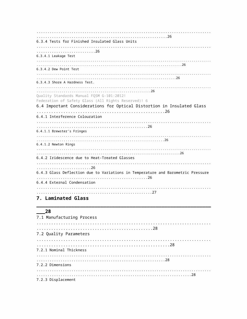
6. Insulated Glass________________________________________________________________256.1 Manufacturing Process........................................................................................................................256.2 Quality Parameters...............................................................................................................................256.2.1 Thickness.........................................................................................................................................................256.2.2 Dimensions.......................................................................................................................................................256.2.3 Displacement / Mismatch.................................................................................................................................256.2.4 Glass Edge Finish.............................................................................................................................................256.2.5 Sealant Protrusion............................................................................................................................................256.2.6 Appearance......................................................................................................................................................256.3 Quality Tests for Insulated Glass Raw Materials..................................................................................266.3.1 Delta-T Test for Desiccant................................................................................................................................266.3.2 Tests for Silicon (Two-Part)...............................................................................................................................266.3.2.1 Butterfly Test.....................................................................................................................................................................266.3.2.2 Peel Adhesion Test............................................................................................................................................................266.3.3 Butyl Quantity Test............................................................................................................................................266.3.4 Tests for Finished Insulated Glass Units...........................................................................................................266.3.4.1 Leakage Test.....................................................................................................................................................................266.3.4.2 Dew Point Test..................................................................................................................................................................266.3.4.3 Shore A Hardness Test......................................................................................................................................................26Quality Standards Manual FQSM G-101:2012!Federation of Safety Glass (All Rights Reserved)! 66.4 Important Considerations for Optical Distortion in Insulated Glass.....................................................266.4.1 Interference Colouration...................................................................................................................................266.4.1.1 Brewster’s Fringes............................................................................................................................................................266.4.1.2 Newton Rings....................................................................................................................................................................266.4.2 Iridescence due to Heat-Treated Glasses.........................................................................................................266.4.3 Glass Deflection due to Variations in Temperature and Barometric Pressure

...................................................266.4.4 External Condensation.....................................................................................................................................27
7. Laminated Glass_______________________________________________________________287.1 Manufacturing Process........................................................................................................................287.2 Quality Parameters...............................................................................................................................287.2.1 Nominal Thickness...........................................................................................................................................287.2.2 Dimensions.......................................................................................................................................................287.2.3 Displacement....................................................................................................................................................287.2.4 Glass Edge Finish.............................................................................................................................................287.2.5 Appearance......................................................................................................................................................287.2.5.1 Common Definitions.........................................................................................................................................................287.2.5.1.1 Spot Defects................................................................................................................................................................287.2.5.1.2 Linear Defects..............................................................................................................................................................287.2.5.1.3 Other Defects...............................................................................................................................................................287.2.5.1.4 Opaque Spots..............................................................................................................................................................297.2.4.1.5 Bubbles........................................................................................................................................................................297.2.5.1.6 Foreign Bodies.............................................................................................................................................................297.2.5.1.7 Scratches or Grazes.....................................................................................................................................................297.2.5.1.8 Vents............................................................................................................................................................................297.2.5.1.9 Creases........................................................................................................................................................................297.2.5.1.10 Streaks due to Interlayer Inhomogeneity:.....................................................................................................................297.2.5.1.11 Edge Area..................................................................................................................................................................297.2.5.1.12 Vision Area.................................................................................................................................................................297.2.5.2 Test Method for Inspection...............................................................................................................................................297.2.5.3 Defects in the Vision Area.................................................................................................................................................297.2.5.3.1 Spot Defects in the Vision Area....................................................................................................................................297.2.5.3.2 Linear Defects in the Vision Area..................................................................................................................................297.2.5.4 Defects in the Edge Area for Framed Glasses...................................................................................................................297.2.5.5 Vents.................................................................................................................................................................................297.2.5.6 Creases and Streaks

.........................................................................................................................................................297.2.5.7 Defects on Edge which will not be Framed........................................................................................................................307.2.6 Tests for Finished Laminated Glass Units.........................................................................................................307.2.6.1 Sampling Plan for Laminated Safety Glass........................................................................................................................307.2.6.2 Boil Test.............................................................................................................................................................................307.2.6.2.1 Principle.......................................................................................................................................................................307.2.6.2.2 Procedure....................................................................................................................................................................307.2.6.2.3 Interpretation of Results................................................................................................................................................30Quality Standards Manual FQSM G-101:2012!Federation of Safety Glass (All Rights Reserved)! 77.2.6.2.4 Acceptance Criteria......................................................................................................................................................307.2.6.3 Humidity Test....................................................................................................................................................................307.2.6.3.1 Principle.......................................................................................................................................................................307.2.6.3.2 Procedure....................................................................................................................................................................307.2.6.3.3 Interpretation of Results................................................................................................................................................307.2.6.3.4 Acceptance Criteria......................................................................................................................................................307.2.6.4 Fracture and Adhesion Test..............................................................................................................................................317.2.6.4.1 Principle.......................................................................................................................................................................317.2.6.4.2 Procedure....................................................................................................................................................................317.2.6.4.3 Acceptance Criteria......................................................................................................................................................31
Notes_________________________________________________________________________32Closing Note____________________________________________________________________34References_____________________________________________________________________35Quality Standards Manual FQSM G-101:2012!Federation of Safety Glass (All Rights Reserved)! 8
1. Definitions1.1 Glass Types1.1.1 Annealed GlassFloat glass or annealed glass (also termed soda limesilicate glass) is a term for perfectly flat, clear glassmanufactured by the float process. This process wasinvented in the UK by Sir Alastair Pilkington in 1959. It isthe most basic type of glass available today and forms thebasis for several fabricated glasses that are used inconstruction. Float glasses have a surface compression
less than 3500psi. For the purpose of conciseness, allstandard terms that follow refer to float glass only andother forms of glass are not considered.1.1.2 Tinted GlassTinted glasses are manufactured by adding colorants tonormal clear float glass during manufacture to achievetinting and solar-radiation absorption properties. The coloris achieved upon the addition of a mineral admixture.Tinting reduces heat and light penetration in buildings ascompared with clear glasses.1.1.3 Coated Float GlassThese are glasses (clear or tinted) that have been coated toreflect solar radiation striking the surface of the glass,thereby reducing solar heat gain. Coatings can be reflectiveor low-emissivity in nature and affect both the visual andthe functional performance of the base glass.1.1.4 Self Cleaning GlassThis is an ordinary float glass with a special photo-catalyticcoating. It has a natural self-cleaning property. The activeintegrated coating on the outside of the glass absorbs thesun’s ultraviolet rays. This causes a reaction on the surfacewhich breaks down dirt and loosens it from the glass. Italso has hydrophobic properties. When it rains or water ispoured over it, it washes the dust off the glass, instead ofleaving it on the glass surface.1.1.5 Anti Reflective GlassIt is a normal float glass, but with a special coating thatallows very little reflection of light. It offers maximum clarityat all times. It has maximum transparency and lowest lightreflection rates and allows optimum viewing through theglass.1.1.6 Extra Clear GlassIt is glass that has an extremely low content of iron, giving ita remarkably clear look. Extra clear glass (also commonlycalled low-iron glass or ultra-clear glass) has the propertyof allowing high light transmission with minimum color,resulting in brilliant optical clarity.1.1.7 Toughened/Tempered GlassToughened or tempered glass is produced when float glasspanels are heated and then cooled rapidly in a controlledenvironment. This process makes the glass several timesstronger than regular glass. It also makes it safer becausewhen broken it yields small pebble-like fragments. In theheat treating process, the annealed glass is subjected to aspecial heat-treatment in which it is heated to about 650⁰Cand afterwards cooled. During the quenching operation thesurface of the glass cools quicker than the interior of theglass so that the residual compression stress is locked intothe surface of the glass. These residual compressionstresses must be overcome before the glass can fracturedue to tensile stresses. The strength of the glass isdetermined by whether the glass is cooled rapidly orslowly.The properties of toughened glasses are as follows:1. Toughened glass can be as much as 5 times stronger

than annealed glass. It resists breakage and canwithstand temperatures between 200⁰C and 300⁰C.2. Surface compression stress is greater than 10000 psi.3. Unlike annealed glasses it breaks into small pieceswithout any sharp edges. For this reason toughenedglass is classified as a safety glass.4. Toughened glass however has a few limitations:a. Once toughened, the glass cannot be cut, drilled,beveled, deep-etched or acid-treated. Therefore, alldesign decisions have to be taken before the glassis processed.b. Tempered glass is prone to spontaneous breakagedue to the presence of nickel sulfide, which cannotbe completely eliminated during the float glassmanufacturing process.c. As it is heat-treated, it can have bows, warps andprocess roll distortion on the surface and this mayinterfere with the optics.Toughened glass is used wherever strength is required andregular annealed glass will not be sufficient, like in high useareas like entrances, in conditions where high wind loadsneed to be taken by the glass surface, etc. Glass facades,sliding doors, building entrances and bath and showerenclosures are the most common uses. Fire knock-outpanels, fireplace enclosures and kitchen objects likevegetable chopping board and cooking pot lids are otheruses.1.1.8 Heat Strengthened GlassThis is a particular heat treated glass that is popular forfacade glazing applications like windows, vision panels andspandrel panels as well as the base material for lamination.Its mechanical strength is twice that of annealed glass andhalf of fully tempered glass. Surface compression isbetween 5000 to 8000 psi. Due to its breakage pattern,monolithic heat-strengthened glass is not classified as asafety glazing material.1.1.9 Heat Soaked GlassThis is simply fully tempered glass that has been processedto reduce the probability of spontaneous breakage due toQuality Standards Manual FQSM G-101:2012!Federation of Safety Glass (All Rights Reserved)! 9nickel sulfide inclusions. Heat soaked glass has shown98.5% reliability in tests1. The glasses have the sameadvantages as fully toughened glass, but are relatively saferas the possibility of breakage is reduced.1.1.10 Laminated GlassThis is composed of two lites of glass permanently bondedtogether with an interlayer material sandwiched in between.Interlayers like PVB (polyvinyl butyral) are bonded into theglass by the application of heat and pressure. Specialsecurity glass and other value-added glass can be made.The two sheets of glass may be regular float glasses,body-tinted, reflective, annealed, heat-strengthened or fullytempered glass, depending on the performance that isrequired. Laminated glass is a completely customizable

product and can perform a wide range of functions.Laminated glass is used as safety glazing in publicbuildings, commercial and retail structures, overheadglazing and large facades. It also serves as security glazingin residences, embassies, banks and combat vehicles andprovides sound control in offices, institutions, malls,residences, airport, bus terminals and recording studios.Other applications include skylights, aquariums, entrancedoors and glass floors2.Laminated glass offers several practical benefits and safetycharacteristics:1. Safety: Laminated glass remains intact when broken,holding glass fragments in place.2. Burglary Resistance: Laminated glass is extremely usefulfor security, and burglar intrusion is greatly minimized.The interlayer continues to be in place even if the glassis broken, increasing security. Ordinary glass cutters andbreak-in tools are not effective on laminated glass as itneeds to be cut in from both the sides. In fact, laminatedglass is the only glass to provide post-breakagestrength.3. Bullet-Resistance: Multiple layers of glass and interlayersprovide resistance to bullet and blast resistance.4. Sound Control: Use of regular and special interlayerscan considerably reduce sound transmission. The viscoelasticproperties of the interlayer have a dampeningeffect on noise.1.1.11 Insulated glassInsulated glass (IG) consists of two glass lites assembledwith a space in between. This space is either left as an airgap or filled with an inert gas for better insulation. IG unitsoffer excellent insulation from heat and have lower UValuesthan monolithic glasses3. Substantial energy savingshave been demonstrated from use of IG glasses as aglazing material when compared to single glazing. Often,insulated glass is used on the surface that takes themaximum direct sunlight. It is also possible to constructinsulated glass units with multiple air gaps and more than 2glass lites.1.1.12 Sandblasted GlassSandblasted glass has a design or form done on it byspraying sand. This texture is rougher than the rest of theglass and it’s translucent. Sand is sprayed at high velocityover the surface of the glass. The area that does not needsandblasting is kept covered during the process. Thedepth and degree of translucence depends on the forceand type of sand used.1.1.13 Etched GlassAcid-etched glass is formed when regular float-glass isacid-etched on one side. Acid etching gives a uniformlysmooth and satin-like effect on the glass. Such glassadmits light while providing softening and vision control. Anindustrially produced glass ensures uniformity of coatingand will not show patching.1.1.14 Lacquered Glass

This is another kind of decorative glass meant for interioruse. It is made by depositing and then baking a coat ofdurable and resistant lacquer to one of the glass surfaces.It is opaque in appearance and combines the advantagesof glass like moisture resistance and highly aestheticsurface shine, while adding opacity.1.1.15 Ceramic GlassThis is a tempered or heat-strengthened glass, one face ofwhich is covered, either partially or totally, with ceramicinks. The color pigment is added while heat strengtheningthe glass. In addition to its decorative function, enameledglass is also a solar ray controller. It can be assembled intolaminated glass or glazed insulation. It is stable, nonbiodegradableand can be made into different figures andshapes. It is used for glazing and cladding in facades,skylights, canopies and floors.Quality Standards Manual FQSM G-101:2012!Federation of Safety Glass (All Rights Reserved)! 101 Please note that even after heat-soaking the probability of NiS suicide is not completely eliminated.2 In overhead glazing (skylights, canopies, etc.) and floors, use of laminated glass should be mandatory to prevent any risk of injury.3 U-Values can be further reduced by use of low emissivity coatings.
2. Float Glass2.1 Manufacturing ProcessFloat glass (also called soda lime silicate glass) ismanufactured by allowing the glass from tank furnace toflow across a bath of molten tin in a controlled atmosphereof nitrogen and hydrogen which yields transparent glasssheet, the surface of which are flat and parallel so that theyprovide clear, undistorted vision and refraction. To knowabout the different quality assurance tests Annexure A mayplease be referred.2.2 Quality Parameters2.2.1 ThicknessThe thickness tolerances of float glass shall be as specifiedin Table 2.1Table 2.1: Thickness and Tolerance of Float Glass4
(All dimensions are in millimeters and as per IS14900 : 2000 (Reaffirmed2005))Nominal Thickness Tolerance*3 ± 0.33.5 ± 0.34 ± 0.35 ± 0.36 ± 0.38 ± 0.610 ± 0.612 ± 0.815 ± 0.819 ± 1.22.2.2 DimensionsTolerance on length and width of the float glass shall be inaccordance with Table 2.2.Table 2.2: Dimensional (Length or Width) Tolerance ofFloat Glass 5(All dimensions are in millimeters and as per IS14900 : 2000 (Reaffirmed2005))Nominal

ThicknessTolerance (Length or Width)Up to and including 3mAbove 3 m3 +1 / -2 -4.0 +1 / -2 -5.0 +2 / -2 -6.0 +2 / -2 -8.0 +2 / -3 +3 / -410.0 +2 / -3 +3 / -412.0 +3 / -3 +4 / -415.0 +3 / -3 +4 / -419.0 +5 / -5 +6 / -62.2.3 DiagonalsTolerance on diagonal of float glass shall be in accordancewith Table 2.3.Table 2.3: Diagonal Tolerance of Float Glass(All dimensions are in millimeters and as per IS14900 : 2000 (Reaffirmed2005))NominalThicknessTolerance (Diagonal)Up to and including 3mAbove 3 m3 +1 / -2 -4.0 +1 / -2 -5.0 +2 / -2 -6.0 +2 / -2 -8.0 +2 / -3 +3 / -410.0 +2 / -3 +3 / -412.0 +3 / -3 +4 / -415.0 +3 / -3 +4 / -419.0 +5 / -5 +6 / -62.2.4 Glass Edge FinishQuality Standards Manual FQSM G-101:2012!Federation of Safety Glass (All Rights Reserved)! 114 Glass thickness shall be measured with a micrometer or caliper which is graduated to 0.01 mm or with a measuring instrument having an equivalentaccuracy.5 Glass dimension shall be measured with a steel scale (tape) which is graduated to 1.00 mm. The measurement shall be made on adjacent two sides.Edge damage usually occurs when cutting the glass(difficulty increases with thickness) and during grinding ofglass. There is no standard acceptance criteria for theedge condition of the glass. Glass with edges that areseverely cut, damaged or have deep, pointed shells/ventsis generally not acceptable. The glass edge finish shouldbe in accordance with Table 2.4.Table 2.4: Glass Edge FinishSNo. Usage Type Finish Allowable Defects1ExposededgesNeatly polished,straight lineSmall glassfragment normallyconchoidal ≤2mm2Silicon or buttjointVisible line shouldbe straightSmall glass

fragment normallyconchoidal ≤2mm3ConcealededgeRough grindingwithout chips anddefectsSmall glassfragment normallyconchoidal ≤3mm2.2.5 Warpage and BowThe allowed warpage and bow tolerance should be inaccordance with Table 2.5Table 2.5: Warpage and Bow Tolerance LimitThickness Sizes Tolerance% MaximumUpto 6mm <3 m 0.3 6 mmUpto 6mm >3 m 0.3 8 mmAbove 6mm <3 m 0.3 6 mmAbove 6mm >3 m 0.3 10 mmCloser tolerances may be required for glasses havingthickness greater than 6 mm in butt jointed applications likepartitions. This should be specified by the customer inadvance and agreed upon specifically between buyer andseller.2.2.6 Surface and Body Defects2.2.6.1 ScratchesScratches shall be classified into the following categories:light, medium and heavy. The allowed scratches should bein accordance with Table 2.6.Table 2.6: Visual Limits for ScratchesS No. Intensity and Size DefinitionNumber/sqm1 Light ScratchShall not bedetectable beyond 50cmAnynumber2Medium Scratch(should not be morethan 15.0 mm)Visible up to 50 -100cm, not visiblebeyond 100 cm23Heavy Scratch Max10 mmVisible up to 150cm,not visible beyond 150cm12.2.6.2 Bubbles / Spots / StonesThe allowed number of bubbles / spots / stones should bein accordance with Table 2.7.Table 2.7: Bubbles / Spots / Stones Visual LimitAll ThicknessesDefect Size(Diameter(d)) No of Defectsd < 0.5mm 2/sqm0.5 < d < 1.0mm 1/sqm

> 1.0mm NilObservation distance 50 cmQuality Standards Manual FQSM G-101:2012!Federation of Safety Glass (All Rights Reserved)! 12
3. Coated Glass3.1 Basic Definitions3.1.1 Coated GlassGlass substrate as defined in 2.1 to which a coating hasbeen applied, as defined in 3.1.2 in order to modify one ormore of its properties.3.1.2 CoatingOne or more thin solid layers of inorganic materials appliedon to the surface of a glass substrate by various methodsof deposition.3.1.3 On-Line CoatingThe treatment of the surface of a moving continuous ribbonof a basic glass, at a stage during its manufacture, before itis cut.3.1.4 Off-line CoatingThe application of a coating to individual pieces of glasswithin a manufacturer's or processor's premises.3.1.5 Additive Methods of DepositionSingle or multilayer systems (consisting of metals, oxides,nitrides, fluorides or other compounds) added to thesurface of the glass by different methods.3.2 Definitions of Appearance Defects3.2.1 Uniformity DefectSlight visible variation in colour, either in reflection ortransmission, within a coated glass pane or from pane topane.3.2.2 StainDefect in the coating larger than punctual defect, oftenirregularly shaped, partially of mottled structure.3.2.3 Punctual DefectPunctual disturbance of the visual transparence lookingthrough the glass and of the visual reflectance looking atthe glass 6.3.2.3.1 SpotDefect that commonly looks dark against the surroundingcoating, when viewed in transmission.3.2.3.2 PinholePunctual void in the coating with partial or total absence ofcoating and it normally contrasts as clear relative to thecoating, when viewed in transmission.3.2.3.3 ScratchVariety of linear score marks, whose visibility depends ontheir length, depth, width, position and arrangements.3.2.4 ClusterAccumulation of very small defects giving the impression ofstain.3.3 Appearance3.3.1 GeneralThe defects affecting appearance are:- Specific to the glass substrate (see 2.2.6), and

- Specific to the coating.If a defect specific to the glass substrate is more visiblebecause of the coating, it will be treated as a coatingdefect.3.3.2 Detection of DefectsThe defects are detected visually by an observation of thecoated glass in transmission and/or reflection. An artificialsky or daylight may be used, as the source of illumination.Daylight illumination is a uniform overcast sky, withoutdirect sunlight.3.3.3 Conditions of Examination3.3.3.1 GeneralCoated glass may be examined in stock size plates or infinished sizes ready for installation. The examination maybe undertaken in the factory or on site when glazed.The pane of coated glass being examined is viewed from aminimum distance of 3 meters. The actual distance will bedependent on the defect being considered and whichillumination source is being used. The examination of thecoated glass in reflection is performed by the observerlooking at the side which will be the outside of the glazing.The examination of the coated glass in transmission isperformed by the observer looking at the side which will bethe inside of the glazing.During the examination the angle between the normal tothe surface of the coated glass and the light beamproceeding to the eyes of the observer after reflection ortransmission by the coated glass shall not exceed 30° (seeFigure 1).Figure 1: Schematics of Examination ProceduresQuality Standards Manual FQSM G-101:2012Federation of Safety Glass (All Rights Reserved)! 136 Spots, pinholes and scratches are types of punctual defects.For panes of coated glass in finished sizes ready to beinstalled both the main area and an edge area of the paneshall be examined (see Figure 2)7.Figure 2: Areas to be Examined on Finished Sizes Readyfor Glazing3.3.3.2 Uniformity Defects and StainsUnder the conditions of examination, given in 3.3.3.1, noteany coating variations either within one pane or betweenneighbouring panes which are visually disturbing.3.3.3.3 Punctual DefectsUnder the conditions of examination, given in 3.3.3.1, noteany spots, pinholes and/or scratches that are visuallydisturbing.For spots and pinholes measure the size and note thenumber relative to the size of the pane. If any clusters arefound, their position relative to the through vision area shallbe determined.For scratches determine whether they are in the main oredge area. Measure the length of any scratches noted. Forscratches greater than 75 mm long determine the distancebetween adjacent scratches. For scratches less than 75mm long note any area where their density produces visualdisturbance.

3.3.4 Acceptance Criteria of Coated Glass DefectsThe acceptance criteria for defects in coated glass,examined according to 3.3.3, are given in Table 3.1.Table 3.1: Coated Glass Acceptance CriteriaDEFECTTYPESACCEPTANCE CRITERIAPane / Pane Individual PaneMain Area Edge AreaUniformity / StainAllowed aslong as notvisuallydisturbingAllowed as long as not visuallydisturbingSpots / Pinholes> 3mm Not Applicable Not allowed Not allowed> 2mm and≤ 3mmNot ApplicableAllowed if notmore than 1/m2
Allowed if notmore than 1/m2
ClustersNot Applicable Not allowedAllowed as longas not in areaof throughvisionScratches> 75mm Not Applicable Not allowedAllowed as longas they areseparated by >50 mm≤ 75mm Not ApplicableAllowed as longas local densityis not visuallydisturbingAllowed as longas local densityis not visuallydisturbingQuality Standards Manual FQSM G-101:2012Federation of Safety Glass (All Rights Reserved)! 147 Each examination will take no more than 20 seconds.
4. Toughened / TemperedGlass4.1 Manufacturing ProcessToughened or tempered glass is produced when float glasspanels are heated and then cooled rapidly in a controlledenvironment. This process makes the glass stronger thanannealed glass. It also makes it safer because whenbroken it yields small pebble-like fragments.4.2 Quality Parameters4.2.1 ThicknessThe thickness tolerance of toughened glasses shall be inaccordance with the tolerances mentioned for annealed

float glasses. Please refer Table 2.1 for details.4.2.2 Dimensions and SquarenessTolerance limits for dimensions for rectangular glass panesare given in Figure 1 and tolerances on width and lengthshould be in accordance with Table 4.1.Figure 4.1: Tolerance Limits for Dimensions of RectangularPanesTable 4.1: Tolerances on Width B and Length H(All dimensions are in millimeters and as per EN12150-1 June 2000)Nominal Dimension ofSide, B or HTolerance, tNominal GlassThickness d ≤ 12Nominal GlassThickness d > 12≤ 2000 2.5 3.02000 < B or H ≤ 3000 3.0 4.0> 3000 4.0 5.04.2.3 Holes and Cutouts4.2.3.1 Hole DimensionsThe allowable hole diameter tolerance should be inaccordance with Table 3.2.Table 4.2: Tolerances on Holes(All dimensions are in millimeters)All ThicknessesHole Diameter RangeDimensionalTolerance4 to 20 ± 121 to 100 ± 2Above 100Consult theManufacturer4.2.3.2 Hole and Cutout LocationThe allowed hole and cutout location tolerance should bein accordance with Table 4.3.Table 4.3: Tolerances on Hole and Cutout Location(All dimensions are in millimeters)All ThicknessesFor holes tolerance should be fromcentre of hole± 1.5mmFor cutouts tolerance should befrom edge± 1.5mm4.2.4 Glass Edge FinishEdge damage usually occurs when cutting the glass(difficulty increases with thickness) and during grinding ofglass. There is no standard acceptance criteria for theedge condition of the glass. Glass with edges that areseverely cut, damaged or have deep, pointed shells/ventsis generally not acceptable. The glass edge finish shouldbe in accordance with Table 4.4.Table 4.4: Glass Edge FinishSNo. Usage Type Finish Allowable Defects1ExposededgesNeatlypolished,straight lineSmall glass fragment

normally conchoidal≤2mm2Silicon orbutt jointVisible lineshould bestraightSmall glass fragmentnormally conchoidal≤2mm3ConcealededgeRough grindingwithout chipsand defectsSmall glass fragmentnormally conchoidal≤3mm4.2.5 Flatness4.2.5.1 General InformationBy the very nature of the toughening process, it is notpossible to obtain a product as flat as annealed glass. Thedifference depends on the nominal thickness, the glasssize dimensions and the ratio between the dimensions.Therefore a distortion known as overall bow can occur.There are two kinds of bow (see Figure 4.3):- overall or general bow- local bowNOTE 1: Overall bow can, in general, be accommodatedby the framing system.NOTE 2: Local bow needs to be allowed for in the glazingmaterials and the weather seals. For special requirementsthe manufacturers should be consulted.Quality Standards Manual FQSM G-101:2012Federation of Safety Glass (All Rights Reserved)! 154.2.5.2 Measurement of Overall BowThe pane of glass shall be placed in a vertical position andsupported on its longer side by two load bearing blocks atthe quarter points (see Figure 4.2). The deformation shallbe measured along the edges of the glass and along thediagonals, as the maximum distance between a straightmetal ruler, or a stretched wire, and the concave surface ofthe glass (see Figure 4.3). The measurement should bedone at room temperature.The value for the bow is then expressed as thedeformation, in millimeters, divided by the measured lengthof the edge of the glass, or diagonal, in millimeters, asappropriate.Figure 4.2: Support Conditions for Measurement of OverallBow(1) B or H(2) (B or H)/2(3) (B or H)/4(4) maximum 100mmFigure 4.3: Representation of Overall and Local Bow(1) deformation for calculating overall bow(2) B or H, or diagonal length(3) local bow(4) 300mm length

4.2.5.3 Warpage and Bow Tolerances4.2.5.3.1 Overall Bow TolerancesThe allowed warpage or overall bow tolerance should be inaccordance with Table 4.5.Table 4.5: Overall Bow (Bend) Tolerance LimitThicknessUp to1.2 m1.2 to2.5 m2.5 to3.05 m3.05 to3.66 mAbove3.66 m4mm 4mm 4mm 6mm NA -5mm 3mm 4mm 5mm 7mm -6mm 3mm 4mm 5mm 7mm -8mm 3mm 4mm 5mm 6mm 10 mm10mm 3mm 4mm 4mm 5mm 10mm12mm 3mm 4mm 4mm 5mm 8mm15mm 3mm 4mm 4mm 6mm 8mm19mm 3mm 4mm 4mm 6mm 10mm4.2.5.3.2 Local Bow TolerancesLocal bow can occur over relatively short distances on theedges of the glass. Local bow shall be measured over alimited length of 300mm by using a straight ruler, or astretched wire, parallel to the edge at a distance of 25 mmfrom the edge of the glass (see Figure 4.3).Quality Standards Manual FQSM G-101:2012Federation of Safety Glass (All Rights Reserved)! 16Local bow is expressed as millimeters / 300 mm length8.The maximum allowable values for the local bow, whenmeasured according to 4.2.5.2, for glass without holesand/or notches and/or cutouts are given in Table 4.69.Table 4.6: Maximum Values for Local BowToughening Process Local Bowmm/300 mmHorizontal 0.5For horizontal tempering, 200mm from either edges parallelto the roller waves shall be excluded from measurement.This method of measurement may not be applicable fornon-rectangular glasses, e.g., triangles and trapezoids.4.2.5.4 Important Considerations for Optical Distortion in FullyToughened Glass10
1. Pressures, exerted around the periphery of glass by theglazing system, can also alter glass flatness therebydistorting reflected images. This is true regardless ofwhether or not the glass is heat treated.2. Sealed insulating glass units also exhibit distortionregardless of glass type. Air or gas, trapped in thesealed airspace between the panes, expands orcontracts with temperature and barometric changes,creating a pressure differential between the airspace andthe atmosphere. The glass reacts to the pressuredifferential by being deflected inward or outward.3. Regardless of glass flatness, the degree of reflecteddistortion perceived is primarily and largely due to thecharacteristics or symmetry of the object being

reflected. Linear objects (such as building curtain wallsand telephone poles) and moving objects (such as cars)may appear distorted. Irregular and free-form objectssuch as trees and clouds will appear to have littleperceived distortion.4. Specified bow and warp limits may not adequatelydefine, or control, the distortion that may becomeapparent after glazing. The factors, noted above, mayhave a larger influence on the perceived reflecteddistortion than that which is caused by bow and warpfrom the heat-treating process. Consultation withsuppliers and the viewing of full-size mockups, undertypical job conditions and surroundings, is highlyrecommended for user or architectural evaluation of thereflective distortion.4.2.6 AppearanceFor surface and body defects in clear or tinted toughenedglasses refer to 2.2.6.For accepted criteria of coated toughened glasses, refer to3.3.4 and all conditions mentioned in Section 3: CoatedGlass.4.2.7 Fragmentation Test4.2.7.1 GeneralThe fragmentation test determines whether the glassbreaks in the manner prescribed for a thermally toughenedsafety float glass. Five specimens shall be tested havingdimensions 360 mm x 1100 mm each, without holes,notches or cutouts.4.2.7.2 Test ProcedureEach test specimen shall be impacted, using a pointedsteel tool, at a position 13 mm in from the longest edge ofthe test specimen at the mid-point of that edge, untilbreakage occurs (see Figure 4.4)11. Examples of steel toolsare a hammer of about 75 gm mass, a spring loadedcentre punch, or other similar appliances with a hardenedpoint. The radius of curvature of the point should beapproximately 0.2 mm.The test specimen shall be laid flat on a table without anymechanical constraint. In order to prevent scattering of thefragments, the specimen shall be simply held at the edges,e.g. by a small frame, adhesive tape etc., so that thefragments remain interlocked after breakage yet extensionof the specimen is not hindered12.Figure 4.4: Position of Impact Point(1) Impact Point4.2.7.3 Assessment of FragmentationThe particle count and measuring of the dimensions of thelargest particle shall be made between 4 minutes to 5minutes after fracture. An area of radius 100 mm, centeredon the impact point, and a border of 25 mm round theQuality Standards Manual FQSM G-101:2012Federation of Safety Glass (All Rights Reserved)! 178 For patterned glass, local bow shall be determined by using a straight ruler resting on the high points of the pattern and measuring to a high point ofthe pattern.9 Source: para 4.2.8 to 4.2.8.4 from EN 12150-1 pages 9 to 12.10 Source: para 7.4.3 to 7.4.6 from ASTM C 1048 - 04.

11 The fragmentation characteristics of glass are unaffected by temperatures between –50°C and +100°C.12 For thermally toughened safety glass manufactured by vertical toughening, the impact point shall not be on the tong mark edge.edge of the test specimen (see Figure 4.5), shall beexcluded from the assessment.Figure 4.5: Area to be Excluded from Particle Count(1) Excluded AreaThe particle count shall be made in the region of coarsestfracture (the aim being to obtain the minimum value). Theparticle count shall be made by placing a mask (50 ± 1)mm x (50 ± 1) mm on the test piece. The number of crackfreeparticles within the mask shall be counted. A particle is'crack-free' if it does not contain any cracks which run fromone edge to another (see Figure 4.6).Figure 4.6: Examples of Crack-Free Particles and theirNumber AssessmentIn the particle count, all particles wholly contained withinthe area of the mask shall be counted as one particle eachand all the particles which are partially within the mask shallbe counted as half particle each (see Figure 4.7 to 4.9).Figure 4.7: Select Area of Coarsest FractureFigure 4.8: Count Perimeter Fragments as 1/2e.g.: Number of Perimeter Particles = 32/2=16Figure 4.9: Count Central Fragments and Add toPerimeter Count to Obtain Final Counte.g.: Number of central fragments = 53, hence total fragments = 16 +53 = 694.2.7.4 Minimum Values from the Particle CountIn order to classify a glass as a fully toughened safety floatglass, the particle count of each test specimen shall not beless than the values given in Table 4.7.Table 4.7: Minimum Particle CountGlass TypeNominalThickness (mm)Minimum ParticleCountFloat and Drawn Sheet3 154 to 12 4015 to 19 30Patterned 4 to 10 304.2.8 Stress Measurement Test4.2.8.1 GeneralStress measurement is a non-destructive test to check thetoughening properties of fully toughened safety float glass.The specimens are examined by the polariscopic or lightrefraction methods13 for surface or edge compression.When the range of the apparatus permits examination foredge compression only, obtain the averaged value for allmidpoints of every edge.4.2.8.2 Test ProcedureQuality Standards Manual FQSM G-101:2012Federation of Safety Glass (All Rights Reserved)! 1813 The most common apparatus to conduct this test is the GASP instrument by Strainoptics Inc. Other methods like DSR may also be used.Two surface compression measurements shall be made ineach of five locations, oriented in two directions at 90° toeach other, for a total of ten readings on each specimen to

be tested. Average the ten readings to determine the stresslevel of the test sample. The five locations to be examinedare shown in Fig. 4.10.Figure 4.10: Five Points to be Examined4.2.8.3 Assessment of MeasurementsFully toughened glass shall have either a minimumsurface compression of 69 MPa (10,000 psi) or an edgecompression of not less than 67 MPa (9,700 psi).4.2.9 MarkingLogo position from corner edge (preferably bottom-right)should be preferably 25mm ± 5mm. All float toughenedglass should have mark ‘TF’ along with brand name.4.3 Other Physical Characteristics4.3.1 Anisotropy (Iridescence)Heat-treated glass (heat-strengthened or tempered) canhave an optical phenomenon that is called strain pattern orquench pattern. This phenomenon can appear as faintspots, blotches, or lines. This is the result of the airquenching (cooling) of the glass when it is heat-treated andshould not be considered a glass defect.The heat treatment process results in a higher surfacecompression directly opposite the air quench, air nozzlesor slots. The higher compression areas are denser and canexhibit a darker appearance under some viewingconditions especially when light is polarized, such as askylight or other forms of reflected light. The colors of thestrain pattern are sometimes referred to as iridescent, orthe general condition as iridescence. The pattern that isseen under certain lighting conditions may vary frommanufacturer, depending on the design of the coolingapparatus. The intensity of the quench or strain pattern isinfluenced by the viewing angle, lighting conditions and bythe perceptiveness of the viewer. It is nearly impossible toeliminate the strain pattern or quench pattern in heattreated glass products.The presence of a strain pattern or the perceivabledifferences in the strain pattern is not a glass defect orblemish and is not cause for rejection. In addition, thepresence of a strain pattern does not alter the structuralintegrity or safety of the glass lite.When viewing from the interior of the building, the quenchpattern may be visible from a 10° viewing angle and notapparent at a 90° viewing angle from the surface ofthe glass. When viewing the glass in reflectance from theexterior of the building, the quench pattern may be visiblewhen looking at the glass surface at a 30-60° angle.Visibility of the quench pattern may be accentuated withthicker glass, tinted glass substrates, coated glass andmultiple lites of heat-treated glass in laminated or insulatingglass products.Construction sites may yield viewing angles and conditionsthat cause the quench pattern to become visible. However,upon completion of construction; the presence of interiorwalls; finishes; furniture; and plants frequently results in thestrain pattern being less visible or not visible at all.

The stresses introduced in the heat-treating of glass arean inherent part of the fabrication process, and while theymay be affected or altered depending on the heatingprocess, controls and/or quench design, they cannot beeliminated. Design professionals should be aware thatquench patterns are not a defect in heat-treated glass and,therefore, are not a basis for product rejection.4.3.2 Spontaneous Breakage due to Nickel Sulphide InclusionsIn various situations fully tempered glass may break for noreason. Many factors might cause such spontaneousbreakages, but the most common are nickel sulphideinclusions. Nickel sulphide inclusion, also known as NiS,occurs during the manufacturing process for float glass. Inthe glass batch, nickel-rich contaminants such as stainlesssteel might be present, and then combine with sulphur toform nickel sulphide inclusions.Nickel sulfide is an interesting compound that exists indifferent phases at different temperatures. Two specificphases of NiS exist, known as the alpha-phase and thebeta-phase. At temperatures below 380°C (715 F), nickelsulfide is stable in the beta-phase. Above this temperature,it is stable in the alpha-phase. Therefore, when glass isproduced in the furnace, it is overwhelmingly likely that anyNiS inclusions will be in the alpha-phase. In typicalannealed glass, the slow cooling process provided by theannealing lehr allows the NiS ample time to transform to itsbeta-phase as the glass cools. However, in the fast coolingprocess used in both heat-strengthened and temperedglass, there is insufficient time to complete the phasetransition (which is a relatively slow process). The inclusionstherefore are “trapped” in the glass in their hightemperaturealpha-phase.However, once the glass cools past the phase changetemperature, the NiS inclusion seeks to reenter its lowerQuality Standards Manual FQSM G-101:2012Federation of Safety Glass (All Rights Reserved)! 19energy beta-phase. For “trapped” inclusions, this processtakes anywhere from months to years. When NiS changesfrom alpha-phase to beta-phase, it increases in volume by2 to 4%. This expansion creates localized tensile stressesthat are estimated to be as much as 125,000 psi (860MPa) at the glass-NiS Interaction surface. The magnitudeof this stress drops off sharply away from the face of theinclusion, but is sufficient at the face to causemicrocracking.In the core tension zone of the glass, these microcracksare propagated by stress concentrations at the tip of thecrack until the structure of the glass is underminedcompletely and the tempered glass undergoes itscharacteristic shattering, which causes the seeminglyspontaneous failure. It is important to understand thatsince there is no data available worldwide on the amount ofNiS inclusions that could occur, breakage due to NiSsuicide is a property, and not a defect in tempered glasses.Quality Standards Manual FQSM G-101:2012!Federation of Safety Glass (All Rights Reserved)! 20

5. Heat-StrengthenedGlass5.1 Manufacturing ProcessHeat-strengthened glass is produced when float glasspanels are heated and then cooled gradually in a controlledenvironment. This process makes the glass stronger thanannealed glass. Since the cooling is more gradual, thestresses formed in heat-strengthened glass is less thanthat of fully tempered glass. Heat-strengthened glasses aretwo times stronger than annealed glasses. They break intorelatively large fragments that stick to its glazing frameworkwhen broken. Heat-strengthened glasses are not classifiedas a safety glazing material.5.2 Quality Parameters5.2.1 ThicknessThe thickness tolerance of toughened glasses shall be inaccordance with the tolerances mentioned for annealedfloat glasses. Please refer Table 2.1 for details.5.2.2 Dimensions and SquarenessTolerance limits for dimensions for rectangular glass panesare given in Figure 1 and tolerances on width and lengthshould be in accordance with Table 5.1.Figure 5.1: Tolerance Limits for Dimensions of RectangularPanesTable 5.1: Tolerances on Width B and Length H(All dimensions are in millimeters and as per EN12150-1 June 2000)Nominal Dimension ofSide, B or HTolerance, tNominal GlassThickness d ≤ 12Nominal GlassThickness d > 12≤ 2000 2.5 3.02000 < B or H ≤ 3000 3.0 4.0> 3000 4.0 5.05.2.3 Holes and Cutouts14
5.2.3.1 Hole DimensionsThe allowable hole diameter tolerance should be inaccordance with Table 5.2.Table 5.2: Tolerances on Holes(All dimensions are in millimeters)All ThicknessesHole Diameter RangeDimensionalTolerance4 to 20 ± 121 to 100 ± 2Above 100Consult theManufacturer5.2.3.2 Hole and Cutout LocationThe allowed hole and cutout location tolerance should bein accordance with Table 5.3.Table 5.3: Tolerances on Hole and Cutout Location(All dimensions are in millimeters)All Thicknesses

For holes tolerance should be fromcentre of hole± 1.5mmFor cutouts tolerance should befrom edge± 1.5mm5.2.4 Glass Edge FinishEdge damage usually occurs when cutting the glass(difficulty increases with thickness) and during grinding ofglass. There is no standard acceptance criteria for theedge condition of the glass. Glass with edges that areseverely cut, damaged or have deep, pointed shells/ventsis generally not acceptable. The glass edge finish shouldbe in accordance with Table 5.4.Table 5.4: Glass Edge FinishSNo. Usage Type Finish Allowable Defects1ExposededgesNeatlypolished,straight lineSmall glass fragmentnormally conchoidal≤2mm2Silicon orbutt jointVisible lineshould bestraightSmall glass fragmentnormally conchoidal≤2mm3ConcealededgeRough grindingwithout chipsand defectsSmall glass fragmentnormally conchoidal≤3mm5.2.5 Flatness5.2.5.1 General InformationBy the very nature of the toughening process, it is notpossible to obtain a product as flat as annealed glass. Thedifference depends on the nominal thickness, the glassQuality Standards Manual FQSM G-101:2012Federation of Safety Glass (All Rights Reserved)! 2114 Please note that since it does not have a high compressive strength, it is not recommended to drill holes and cutouts in heat-strengthenedglasses.size dimensions and the ratio between the dimensions.Therefore a distortion known as overall bow can occur.There are two kinds of bow (see Figure 4.3):- overall or general bow- local bowNOTE 1: Overall bow can, in general, be accommodatedby the framing system.NOTE 2: Local bow needs to be allowed for in the glazingmaterials and the weather seals. For special requirementsthe manufacturers should be consulted.

5.2.5.2 Measurement of Overall BowThe pane of glass shall be placed in a vertical position andsupported on its longer side by two load bearing blocks atthe quarter points (see Figure 5.2). The deformation shallbe measured along the edges of the glass and along thediagonals, as the maximum distance between a straightmetal ruler, or a stretched wire, and the concave surface ofthe glass (see Figure 5.3). The measurement should bedone at room temperature.The value for the bow is then expressed as thedeformation, in millimeters, divided by the measured lengthof the edge of the glass, or diagonal, in millimeters, asappropriate.Figure 5.2: Support Conditions for Measurement of OverallBow(1) B or H(2) (B or H)/2(3) (B or H)/4(4) maximum 100mmFigure 5.3: Representation of Overall and Local Bow(1) deformation for calculating overall bow(2) B or H, or diagonal length(3) local bow(4) 300mm length5.2.5.3 Warpage and Bow Tolerances5.2.5.3.1 Overall bow TolerancesThe allowed warpage or overall bow tolerance should be inaccordance with Table 5.5.Table 5.5: Overall Bow (Bend) Tolerance LimitThicknessUp to1.2 m1.2 to2.5 m2.5 to3.05 m3.05 to3.66 mAbove3.66 m4mm 4mm 4mm 6mm NA -5mm 3mm 4mm 5mm 7mm -6mm 3mm 4mm 5mm 7mm -8mm 3mm 4mm 5mm 6mm 10 mm10mm 3mm 4mm 4mm 5mm 10mm12mm 3mm 4mm 4mm 5mm 8mm5.2.5.3.2 Local Bow TolerancesLocal bow can occur over relatively short distances on theedges of the glass. Local bow shall be measured over alimited length of 300mm by using a straight ruler, or astretched wire, parallel to the edge at a distance of 25 mmfrom the edge of the glass (see Figure 5.3).Local bow is expressed as millimeters / 300 mm length15.Quality Standards Manual FQSM G-101:2012Federation of Safety Glass (All Rights Reserved)! 2215 For patterned glass, local bow shall be determined by using a straight ruler resting on the high points of the pattern and measuring to a high point ofthe pattern.The maximum allowable values for the local bow, whenmeasured according to 5.2.5.2, for glass without holesand/or notches and/or cutouts are given in Table 5.616.

Table 5.6: Maximum Values for Local BowToughening Process Local Bowmm/300 mmHorizontal 0.5For horizontal tempering, 200mm from either edges parallelto the roller waves shall be excluded from measurement.This method of measurement may not be applicable fornon-rectangular glasses, e.g., triangles and trapezoids.5.2.5.4 Important Considerations for Optical Distortion in Heat-Strengthened Glass17
1. Pressures, exerted around the periphery of glass by theglazing system, can also alter glass flatness therebydistorting reflected images. This is true regardless ofwhether or not the glass is heat treated.2. Sealed insulating glass units also exhibit distortionregardless of glass type. Air or gas, trapped in thesealed airspace between the panes, expands orcontracts with temperature and barometric changes,creating a pressure differential between the airspace andthe atmosphere. The glass reacts to the pressuredifferential by being deflected inward or outward.3. Regardless of glass flatness, the degree of reflecteddistortion perceived is primarily and largely due to thecharacteristics or symmetry of the object beingreflected. Linear objects (such as building curtain wallsand telephone poles) and moving objects (such as cars)may appear distorted. Irregular and free-form objectssuch as trees and clouds will appear to have littleperceived distortion.4. Specified bow and warp limits may not adequatelydefine, or control, the distortion that may becomeapparent after glazing. The factors, noted above, mayhave a larger influence on the perceived reflecteddistortion than that which is caused by bow and warpfrom the heat-treating process. Consultation withsuppliers and the viewing of full-size mockups, undertypical job conditions and surroundings, is highlyrecommended for user or architectural evaluation of thereflective distortion.5.2.6 AppearanceFor surface and body defects in clear or tinted toughenedglasses refer to 2.2.6.For accepted criteria of coated toughened glasses, refer to3.3.4 and all conditions mentioned in Section 3: CoatedGlass.5.2.7 Stress Measurement Test5.2.7.1 GeneralStress measurement is a non-destructive test to check thetoughening properties of fully toughened safety float glass.The specimens are examined by the polariscopic or lightrefraction methods18 for surface or edge compression.When the range of the apparatus permits examination foredge compression only, obtain the averaged value for allmidpoints of every edge.5.2.7.2 Test ProcedureTwo surface compression measurements shall be made in

each of five locations, oriented in two directions at 90° toeach other, for a total of ten readings on each specimen tobe tested. Average the ten readings to determine the stresslevel of the test sample. The five locations to be examinedare shown in Fig. 4.10.Figure 5.4: Five Points to be Examined5.2.7.3 Assessment of MeasurementsHeat-strengthened glass with thicknesses of 6 mm andless19 shall have a surface compression between 24 to52 MPa (3,500 to 7,000 psi) or an edge compression ofnot less than 67 MPa (9,700 psi).5.2.8 MarkingLogo position from a corner edge (preferably bottom right)should be preferably 25mm ± 5mm. All float heatstrengthenedglass should have mark ‘HS’ along withbrand name.5.3 Other Physical Characteristics5.3.1 Anisotropy (Iridescence)Quality Standards Manual FQSM G-101:2012Federation of Safety Glass (All Rights Reserved)! 2316 Source: para 4.2.8 to 4.2.8.4 from EN 12150-1 pages 9 to 12.17 Source: para 7.4.3 to 7.4.6 from ASTM C 1048 - 04.18 The most common apparatus to conduct this test is the GASP instrument by Strainoptics Inc. Other methods like DSR may also be used.19 Heat strengthening of glass thicker than 6 mm (1⁄4 in.) within narrow limits of surface compression is difficult. Consult manufacturer.Heat-treated glass (heat-strengthened or tempered) canhave an optical phenomenon that is called strain pattern orquench pattern. This phenomenon can appear as faintspots, blotches, or lines. This is the result of the airquenching (cooling) of the glass when it is heat-treated andshould not be considered a glass defect.The heat treatment process results in a higher surfacecompression directly opposite the air quench, air nozzlesor slots. The higher compression areas are denser and canexhibit a darker appearance under some viewingconditions especially when light is polarized, such as askylight or other forms of reflected light. The colors of thestrain pattern are sometimes referred to as iridescent, orthe general condition as iridescence. The pattern that isseen under certain lighting conditions may vary frommanufacturer, depending on the design of the coolingapparatus. The intensity of the quench or strain pattern isinfluenced by the viewing angle, lighting conditions and bythe perceptiveness of the viewer. It is nearly impossible toeliminate the strain pattern or quench pattern in heattreated glass products.The presence of a strain pattern or the perceivabledifferences in the strain pattern is not a glass defect orblemish and is not cause for rejection. In addition, thepresence of a strain pattern does not alter the structuralintegrity or safety of the glass lite.When viewing from the interior of the building, the quenchpattern may be visible from a 10° viewing angle and notapparent at a 90° viewing angle from the surface ofthe glass. When viewing the glass in reflectance from the

exterior of the building, the quench pattern may be visiblewhen looking at the glass surface at a 30-60° angle.Visibility of the quench pattern may be accentuated withthicker glass, tinted glass substrates, coated glass andmultiple lites of heat-treated glass in laminated or insulatingglass products.Construction sites may yield viewing angles and conditionsthat cause the quench pattern to become visible. However,upon completion of construction; the presence of interiorwalls; finishes; furniture; and plants frequently results in thestrain pattern being less visible or not visible at all.The stresses introduced in the heat-treating of glass arean inherent part of the fabrication process, and while theymay be affected or altered depending on the heatingprocess, controls and/or quench design, they cannot beeliminated. Design professionals should be aware thatquench patterns are not a defect in heat-treated glass and,therefore, are not a basis for product rejection.Quality Standards Manual FQSM G-101:2012!Federation of Safety Glass (All Rights Reserved)! 24
6. Insulated Glass6.1 Manufacturing ProcessInsulated glasses are two or more panels of glass spacedapart and hermetically sealed to form a single unit with anair or gas space between each panel. Typically the spaceris made of aluminum that is either mill-finished or painted/anodized in different colours/finishes. Desiccants are filledinside the spacer framework to prevent condensationinside the air gap. Butyl is the most popular primary sealantthat joins the spacer to both glass lites. The secondarysealant can be either silicon (used for structural glazing), orpolysulphide or polyurethane (used in window glasses).6.2 Quality Parameters6.2.1 ThicknessDual-pane Insulated glass units shall conform to thenominal thickness values specified in Table 6.1.Table 6.1: Thickness Tolerance of IGUAll dimensions in millimetersFirst Pane Second PaneIGU ThicknessToleranceAnnealed Glass Annealed Glass ± 1.0Annealed GlassToughened or Heat-Strengthened Glass± 1.5Toughened or Heat-Strengthened GlassToughened or Heat-Strengthened Glass± 1.5The thickness tolerances of multi-cavity insulating glassunits are obtained by using the following rules:a) determine the tolerance of each composition glass/cavity/glass in accordance with Table 6.1;b) calculate the squares of those values;

c) sum all those square values;d) calculate the square root of that sum.6.2.2 DimensionsTolerance limits for dimensions for rectangular glass panesare given in Figure 6.1 and tolerances on width and lengthshould be in accordance with Table 6.2.Figure 6.1: Tolerance Limits for Dimensions of RectangularInsulated Glass PanesTable 6.2: Tolerances on Width B and Length H(All dimensions are in millimeters and as per EN12150-1 June 2000)Nominal Dimension ofSide, B or HTolerance, tNominal GlassThickness d ≤ 12Nominal GlassThickness d > 12≤ 2000 2.5 3.02000 < B or H ≤ 3000 3.0 4.0> 3000 4.0 5.06.2.3 Displacement / MismatchDisplacement/mismatch tolerance between the two glasspanes shall be in accordance with Table 6.3.Table 6.3: Displacement and Mismatch Tolerance LimitAll Thickness All Available Range of Dimensions ± 2.06.2.4 Glass Edge FinishSince most insulated glass units are used in applicationswhere edges are either concealed or sealed withsecondary sealant, it is generally not required to haveglasses with polished or perfectly ground edges. In mostcases arising of the edges is generally enough. However, itis recommended to have the edge finish specified as partof the quality contract with the customer.6.2.5 Sealant ProtrusionThe allowed primary sealant protrusion should be inaccordance with Table 6.420.Table 6.4: Allowed Sealant ProtrusionAll Thickness Uniform Application of Sealant ± 2.06.2.6 AppearanceFor surface and body defects in insulated glass unitsconsisting of clear or tinted glasses refer to 2.2.6.For accepted criteria of insulated glass units consisting ofcoated glasses, refer to 3.3.4 and all conditions mentionedQuality Standards Manual FQSM G-101:2012Federation of Safety Glass (All Rights Reserved)! 2520 Although slight variations is butyl application straightness is allowed, it is absolutely critical that there are no breaks in sealant application andthe line is continuous, to protect against failures of the insulated unit over its life cycle.in Section 3: Coated Glass.6.3 Quality Tests for Insulated Glass Raw Materials6.3.1 Delta-T Test for DesiccantThis test is used to check the adsorption capacity ofdesiccants used in insulated glass units.1. Take room temperature water in a beaker and measureits initial temperature (Ti) and quantity.2. Add equal quantity of desiccant in milligrams (mg). Nowthe temperature of water will start rising automatically.3. Wait till the temperature of water reaches the maximum
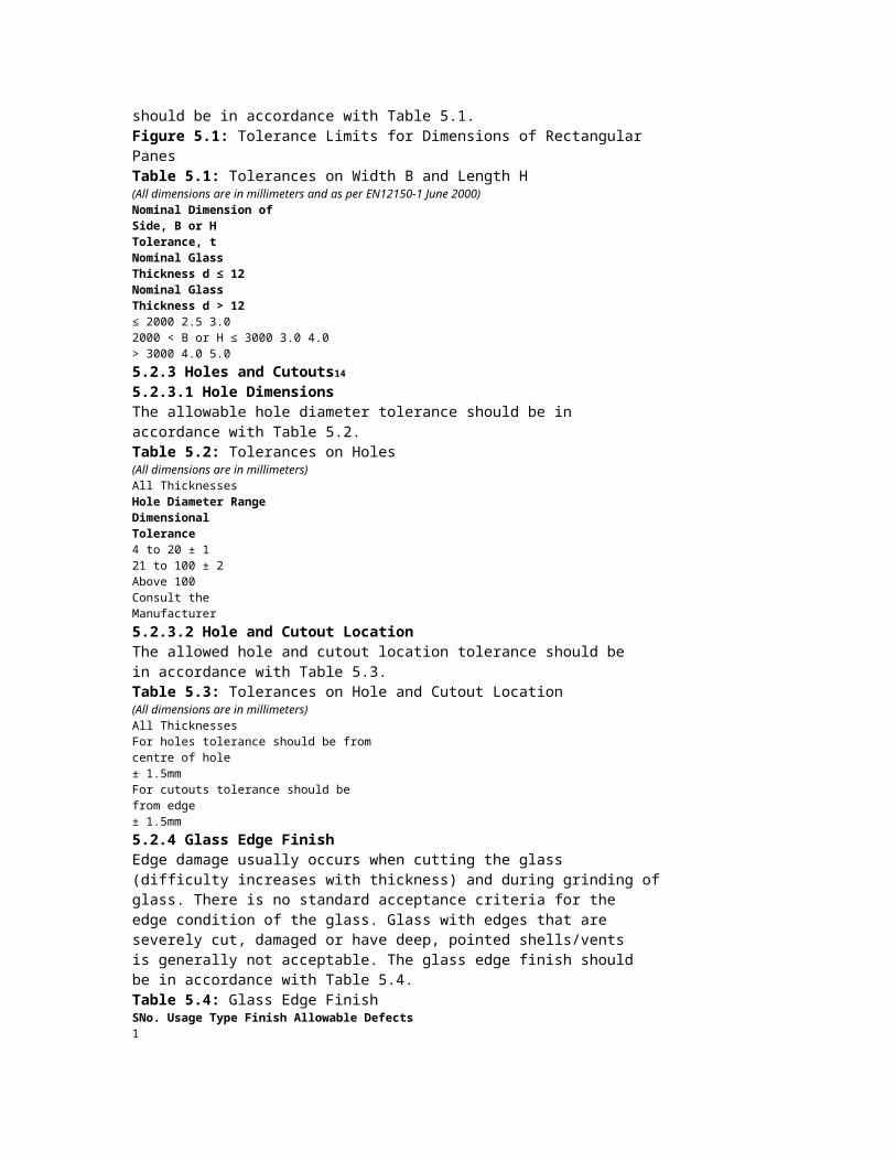
value.4. Measure the final temperature (Tf).5. Calculate ΔT = Tf – Ti. ΔT should be more than 32°C.6.3.2 Tests for Silicon (Two-Part)It is very important that two part sealant be checkedproperly to ensure well curing. Improper mixing of siliconwill result in adhesion failure and eventually lead to unitfailure.6.3.2.1 Butterfly TestThe purpose of butterfly test is to check for an adequatemixing of the base and catalyst components. The test isperformed by dispensing a bead of sealant on to a piece ofwhite paper and folding the paper in half, smearing downthe sealing bead. Then the paper is reopened andinspected visually. This should appear uniform in colourwith no white streaks.6.3.2.2 Peel Adhesion TestThe purpose of this test is to verify adhesion of sealant tothe glass substrate. An adhesive or cohesive failure ofsilicon with glass substrate can result due to impropercuring of silicon or bad raw material quality.1. Clean and prime the substrate.2. Place a piece of bond breaker tape across the flatsurface.3. Apply a bead of sealant and tool it to form a stripapproximately 20 cm long, 1.5 cm wide and 6 mm thick.At least 4 cm of the sealant should be applied over thebond breaker tape.4. After sealant cure, grasp the 4 cm tab of sealant whichoverlays the bond breaker tape. Pull the sealant at a180° angle. Peel back only 1 to 2 cm of sealant leavingthe remainder in place for additional testing.5. If the sealant tears within itself and remains fully bondedto the substrate, this is called “cohesive failure”. 100%cohesive failure is desirable since this indicates that thestrength of adhesion is greater than the strength ofcohesion.6.3.3 Butyl Quantity TestThis test is used to calculate the minimum quantity of butylapplied on a spacer. Butyl needs to be applied on spacersin a certain minimum quantity to effectively provide aprimary glass to spacer seal.1. Take a spacer system from running production andextrude butyl under standard production conditions.2. Remove the butyl from the spacer.3. Measure the weight of butyl.4. Measure the length of the spacer system.5. Calculate the ratio (length:weight) and calculate theweight of butyl per running meter.6. The butyl quantity should be more than or equal to 2.7grams per side per running meter6.3.4 Tests for Finished Insulated Glass Units6.3.4.1 Leakage TestThe insulated glass specimen is dropped in a water tankfor five minutes. There should be no bubbles appearing in

the water tank and no seepage of water inside theinsulated glass unit.6.3.4.2 Dew Point TestThe dew point temperature test is used to check thehumidity content in the insulated glass unit air space. Asample is cooled down until condensation (dew) forms onthe interior surface. This dew point should be minimum-40°C.6.3.4.3 Shore A Hardness TestThe insulated glass sample is cured for a total of 24 hoursand a Shore A hardness meter is used to check thehardness of the cured silicon sealant. For structural siliconthe Shore A hardness reading should be minimum 43.6.4 Important Considerations for Optical Distortion inInsulated Glass6.4.1 Interference Colouration6.4.1.1 Brewster’s FringesWhen the glass pane surfaces exhibit near perfectparallelism and the surface quality is high, the insulatedglass pane shows interference coloration. These are linesvarying in colour as a result of decomposition of the lightspectrum. When the sun is the light source, the coloursvary from red to blue. This phenomenon is not considereda defect but it is inherent to the insulated glass unitconstruction.6.4.1.2 Newton RingsThis optical effect only occurs in faulty insulated glass unitsand occurs when the two panes of glass are touching ornearly touching in the centre. The optical effect is a seriesof concentric coloured rings with the centre being in thepoint of contact/near contact of the two panes. The ringsare roughly circular or elliptical.6.4.2 Iridescence due to Heat-Treated GlassesSome processed glasses also show coloration inherent tothe product, e.g. toughened glass and heat strengthenedglass. Refer to sections 4.2.9.1 and 5.2.9.1 for details.6.4.3 Glass Deflection due to Variations in Temperature andBarometric PressureTemperature variations of the space filled with air and/orgas and barometric pressure variations of the atmosphereand altitude will contract or expand the air and/or gas inthe cavity and consequently deflections of the glass panewill occur, resulting in distortion of reflected images. TheseQuality Standards Manual FQSM G-101:2012!Federation of Safety Glass (All Rights Reserved)! 26deflections, which cannot be prevented, show variationsover time. The magnitude depends partially on the stiffnessand size of the glass panes, as well as on the width of thecavity. Small sizes, thick glasses, and/or small cavitiesreduce these deflections significantly.6.4.4 External CondensationExternal condensation on insulated glass units may occureither inside or outside the building. When it is inside thebuilding, it is principally due to high humidity in the room,together with a low outside temperature. Kitchens,

bathrooms, and other high humidity areas are particularlysusceptible. When it is outside the building, condensationis principally due to nocturnal heat loss of the outside glasssurface by infrared radiation to a clear sky, together withhigh humidity, but no rain, in the outside atmosphere.These phenomena do not constitute failures of theinsulating glass, but are due to atmospheric conditions.Quality Standards Manual FQSM G-101:2012!Federation of Safety Glass (All Rights Reserved)! 27
7. Laminated Glass7.1 Manufacturing ProcessLaminated glasses are constructed using two glasslites and joining them by using an interlayer inbetween under temperature and high pressure.Polyvinyl butyral (PVB) is the most common form ofinterlayer used21. Interlayers can be either clear orcoloured and is available in transparent, translucent oropaque form depending on requirement.7.2 Quality Parameters7.2.1 Nominal ThicknessThe nominal thickness of laminated glass shall be the sumof the nominal thickness of constituent panes of glass andinterlayer material.The thickness of the pane shall be calculated as the meanof measurements taken at the centers of the four sides.The measurements shall be taken to an accuracy of0.01mm and the mean is then rounded to the nearest0.1mm. The individual measurements when rounded to thenearest 0.1mm shall also be within the limit deviation.7.2.2 DimensionsTolerance limits for dimensions for rectangular glass panesare given in Figure 7.1 and tolerances on width and lengthshould be in accordance with Table 7.1.Figure 7.1: Tolerance Limits for Dimensions of RectangularPanesTable 7.1: Tolerances on Width B and Length H(All dimensions are in millimeters and as per EN12543-5: 1998)Limit Deviations t on Width B or Length HNominalDimension ofSide, B or HNominalGlassThickness d≤ 8 mmNominal Glass Thickness d >8 mmEach GlassPane < 10 mmThicknessAt Least OneGlass Pane ≥10 mmThicknes< 1100 +2 / -2 +2 / -2 +3 / -2.5
< 2440 +3 / -2 +3 / -2 +4 / -3

> 2440 +4 / -3 +4 / -3 +4.5 / -4
7.2.3 DisplacementDisplacement is the misalignment at any one edge of theconstituent glass panes making up the laminated glass.The maximum allowable displacement is as given in Table7.2.Table 7.2: Maximum Displacement in Laminated Glass(All dimensions are in millimeters and as per EN12543-5: 1998)Nominal Dimension of Side, B or HMaximum PermissibleDisplacementB, H ≤ 1000 2.0
1000 < B, H ≤ 2000 3.0
2000 < B, H ≤ 4000 4.0
B, H > 4000 5.0
7.2.4 Glass Edge FinishOnce the glass is toughened or heat-strengthened, it shallnot be edge-worked after making into a laminate. Thesepanels need to be individually worked upon beforetoughening and then assembled into a laminate.For details of acceptable edge finishes refer to the relevanttoughened and heat-strengthened standards (4.2.4 and5.2.4 respectively).7.2.5 Appearance7.2.5.1 Common Definitions7.2.5.1.1 Spot DefectsThis type of defect includes opaque spots, bubbles andforeign bodies.7.2.5.1.2 Linear DefectsThis type of defect includes foreign bodies and scratchesor grazes.7.2.5.1.3 Other DefectsQuality Standards Manual FQSM G-101:2012Federation of Safety Glass (All Rights Reserved)! 2821 Newer forms of interlayers such as ionomers are also getting increasingly popular.Glass defects such as vents and interlayer defects such ascreases, shrinkage and streaks.7.2.5.1.4 Opaque SpotsVisible defects in the laminated glass (for e.g., tin marks,inclusions in the glass or interlayer).7.2.4.1.5 BubblesUsually air bubbles, these can be in the glass or in theinterlayer.7.2.5.1.6 Foreign BodiesAny unwanted item introduced into the laminated glassduring manufacture.7.2.5.1.7 Scratches or GrazesLinear damage to the outside surface of the laminatedglass.7.2.5.1.8 VentsSharp tipped fissures or cracks running into the glass froman edge.7.2.5.1.9 CreasesDistortions introduced into the interlayer by folds visibleafter manufacture.7.2.5.1.10 Streaks due to Interlayer Inhomogeneity:

Optical distortions in the interlayer that are caused bymanufacturing defects in the interlayer, and are visible aftermanufacture.7.2.5.1.11 Edge AreaFor panes sizes ≤ 5m2 the width of the edge area is 15mm. The edge area width is increased to 20 mm for panesizes > 5m2.7.2.5.1.12 Vision AreaThe area outside of the edge area is called as vision area.7.2.5.2 Test Method for InspectionThe laminated glass to be observed is put in a verticalposition, in front of and parallel to a matt grey screen, lit bydiffused daylight or equivalent. The observer will be at adistance of 2 meters from the glass and shall observe itperpendicularly (the matt screen being on the other side ofthe glass). Defects that are disturbing when viewed shall bemarked.7.2.5.3 Defects in the Vision Area7.2.5.3.1 Spot Defects in the Vision AreaWhen inspected according to the test method stated in7.2.4.2, the admissibility of spot defects depends on thefollowing:- Size of the defect- Frequency of the defect- Size of the pane- Number of panes as components of a laminated glass.This is expressed in Table 7.3.Table 7.3: Permissible Spot Defects in the Vision AreaSize of Defect d inmm0.5 < d ≤ 1.0 1.0 < d ≤ 3.0Size of Pane A in m2 For all Sizes A ≤ 1 1 < A ≤ 2 2 < A ≤ 8 A > 8NumberofAllowedDefects2 PanesNo limitation,however noaccumulationof defects1 2 1 / m2 1.2 / m2
3 Panes 2 3 1.5 / m2 1.8 / m2 4 Panes3 4 2 / m2 2.4 / m2
≥ 5Panes4 5 2.5 / m2 3 / m2
Defects less than 0.5 mm are not considered and defectsgreater than 3 mm are not permitted22.An accumulation of defects occurs if four or more defectsare at a distance of < 200 mm from each other. Thisdistance is reduced to:- 180 mm for laminated glass consisting of three panes,- 150 mm laminated glass consisting of 4 panes, and- 100 mm laminated glass consisting of five or more panes.The number of permissible defects in Table 7.1 shall beincreased by 1 for each individual interlayer which is thickerthan 2 mm.7.2.5.3.2 Linear Defects in the Vision AreaWhen inspected according to the test method given in7.2.4.2, the linear defects are allowed as given in Table 7.2.Table 7.2: Number of Permissible Defects in the VisionArea

Area of PaneNumber of PermissibleDefects ≥ 30 mm in Length≤ 5 m2 Not Allowed5 to 8 m2 1> 8 m2 2Linear defects less than 30 mm in length are allowed.7.2.5.4 Defects in the Edge Area for Framed GlassesWhen inspected according to the test method stated in7.2.4.2, defects which do not exceed 5 mm in diameter arepermitted in the edge area. If bubbles are present, thebubbled area shall not exceed 5% of the edge area.7.2.5.5 VentsVents are not permitted.7.2.5.6 Creases and StreaksThese are not allowed in the visual area.Quality Standards Manual FQSM G-101:2012!Federation of Safety Glass (All Rights Reserved)! 2922 Admissibility of spot defects in laminated glass is independent of the individual glass thickness.7.2.5.7 Defects on Edge which will not be FramedLaminated glass is usually installed in frames; when it isunframed, its edges may be- ground edges,- polished edges, or- bevelled edges.In such conditions shells, bubbles, interlayer defects andretractions are permissible if they do not become obviouswhen subjected to the test method in 7.2.4.2.7.2.6 Tests for Finished Laminated Glass Units7.2.6.1 Sampling Plan for Laminated Safety GlassTest specimens should be representative of standardproduction. Test specimens should either be speciallymanufactured to the test size or be cut from largerpanes. Test specimen with cut edges should contain atleast one edge from the original pane from which it wascut. If the final product has all its edges sealed/protectedthen the test specimen should also have all its edgessealed/protected.The method of supporting the test specimen shall notcover two edges of the test specimen. If the testspecimen is cut from a larger pane at least one originaledge shall not be covered.Inspect the samples prior to the test at a distancebetween 30 cm and 50 cm in front of a white diffusebackground. Only samples free of faults (bubbles,delamination, cloudiness) shall be used for the test.7.2.6.2 Boil Test7.2.6.2.1 PrincipleThis test is used to determine whether the laminated safetyglass will withstand exposure to high temperatures over anextended period of time without its properties beingsubstantially altered.7.2.6.2.2 ProcedureThree test specimens of size 100 X 300 mm shall be used.Immerse all the three test specimens vertically, supportedon its edge23, first in water at 65 ± 2°C for three minutesand then immediately in boiling water for two hours.

7.2.6.2.3 Interpretation of ResultsThe samples are removed from the boiling water bath andinspected between 30 and 50 cm in front of a white diffusebackground.Record the number and extent of the faults occurring in theinterlayer (bubbles, delamination and cloudiness, but notdiscolouration) for each test specimen. Disregard all faultswithin 15 mm from an original edge and 25 mm from a cutedge24.Delamination taken as a criterion for evaluation after theboil test, may be described as essentially a twodimensional phenomena, in the interface between the glassand the interlayer, in which area no adhesion exists.7.2.6.2.4 Acceptance CriteriaNo faults (bubbles, delamination, cloudiness) shall be foundin the three test specimens, as per the interpretationcriteria mentioned in 7.2.5.1.3. If faults are found in onlyone test specimen, a further test may be carried out onthree new test specimens, in which case no faults shall befound in any of these test specimens.7.2.6.3 Humidity Test7.2.6.3.1 PrincipleThis test is used to determine whether the laminated safetyglass will withstand exposure to atmospheric humidity overan extended period of time without its properties beingsubstantially altered.7.2.6.3.2 ProcedureThree test specimens of size 100 X 300 mm shall be used.Keep all the three test specimens vertically, supported onits edge25, over water in a closed container. The airtemperature within the container should be maintainedwithin the limits of 50°C26.7.2.6.3.3 Interpretation of ResultsThe samples are removed from the boiling water bath andinspected between 30 and 50 cm in front of a white diffusebackground.Record the number and extent of the faults occurring in theinterlayer (bubbles, delamination and cloudiness, but notdiscolouration) for each test specimen. Disregard all faultswithin 15 mm from an original edge, 25 mm from a cutedge or 10 mm from any crack27.Delamination taken as a criterion for evaluation after thehumidity test, may be described as essentially a twodimensional phenomena, in the interface between the glassand the interlayer, in which area no adhesion exists.7.2.6.3.4 Acceptance CriteriaQuality Standards Manual FQSM G-101:2012!Federation of Safety Glass (All Rights Reserved)! 3023 The specimen shall be kept in the vessel of boiling water in such a way as not to touch the bottom of the testing vessel directly. A suitablearrangement may be used.24 If wire or mesh inlays are used, individual bubbles in the immediate vicinity of inlaid wires are permissible.25 The specimen shall be kept in the vessel of boiling water in such a way as not to touch the bottom of the testing vessel directly. A suitablearrangement may be used.

26 These conditions give a relative humidity of about 100% and will lead to water condensation on the surface of the test specimen.27 If wire or mesh inlays are used, individual bubbles in the immediate vicinity of inlaid wires are permissible.No faults (bubbles, delamination, cloudiness) shall be foundin the three test specimens, as per the interpretationcriteria mentioned in 7.2.5.2.3. If faults are found in onlyone test specimen, a further test may be carried out onthree new test specimens, in which case no faults shall befound in any of these test specimens.7.2.6.4 Fracture and Adhesion Test7.2.6.4.1 PrincipleThe purpose of this test is to test the integrity of thelaminated glass sample when subjected to external forcedimpact. The laminated safety glass is given a suddenpunch and fragments from the under-surface are collectedand weighed.7.2.6.4.2 ProcedureA hardened steel wall with a diameter of 38 mm andweighing about 225 g shall be used for the test. A squarehard wood frame shall be constructed so that when thetest specimen rests symmetrically on the frame, 290 X 290mm of the specimen shall remain unsupported. The frameshall be rigidly mounted on a 12 mm steel plate and thescrews or bolts used for attaching it to the steel plate shallnot project below the under-surface of the plate. Thecomplete frame shall stand upon a substantial concretebed.A means for dropping the ball freely from a height of 4.88meters shall be provided such that it strikes the specimenwithin 25 mm from its centre28.Ten specimens of 300 X 300 mm shall be tested. Prior tothe test each specimen shall be weighed. The specimensshall be kept at 27 ± 2°C for four hours immediatelypreceding the test. Each specimen in turn shall besupported on the wooden frame in such a way that theplane of the test specimen when in the frame shall besubstantially horizontal. The ball shall be dropped asdescribed above. The fragments from the under-surface ofeach specimen shall be separately collected and weighed.7.2.6.4.3 Acceptance CriteriaThe test specimens shall be deemed acceptable if out ofthe ten specimens tested:1. the number of specimens shown to be pierced29 in thetest does not exceed four, of which not more than twoare brittle30, and2. if the total weight of the fragments from the underside ofthe unpierced specimens does not exceed 0.5 percentof the total weight of these unpierced specimens, and3. if no unpierced specimen yields any fragment whichindividually weighs more than 0.5 grams.Quality Standards Manual FQSM G-101:2012!Federation of Safety Glass (All Rights Reserved)! 3128 An electro-magnet may conveniently be used for this purpose.29 The specimen will be deemed to have been pierced if a split or tear exceeding 38 mm in length develops in the interlayer.

30 A pierced specimen shall be deemed to be brittle if the breaks into two or more large pieces, or if the fracture is sufficient to allow the ball to passthrough.
NotesQuality Standards Manual FQSM G-101:2012!Federation of Safety Glass (All Rights Reserved)! 32
NotesQuality Standards Manual FQSM G-101:2012!Federation of Safety Glass (All Rights Reserved)! 33
Closing NoteThis Quality Standards Manual is intended to serve as a single-point quality reference guide for glassprocessors, aluminum fabricators, facade consultants, architects and developers. While formulatingthese guidelines we have looked upon various relevant world standards in existence and have basedour tolerances considering a pragmatic approach on both the manufacturing and installation fronts.Wherever possible, we have used the most stringent limits from available standards, which willfacilitate dispute resolution when required.Although detailed attention has been given to ensure that this manual is complete and comprehensivein all respects, we invite suggestions for improving this guide and make it more workable formanufacturing and installation purposes. Please do write to us and we shall incorporate your valuablesuggestions in the forthcoming editions.Tariq KachwalaHon. General Secretary, Federation of Safety GlassMumbaiJuly 2012Quality Standards Manual FQSM G-101:2012!Federation of Safety Glass (All Rights Reserved)! 34
References- IS 2553 (Part 1) - 1990 - Safety Glass - Specification- IS 2835 - 1987 - Specification For Flat Transparent Sheet Glass (Third Revision)- IS 875 (Part 3) Reaffirmed 1997 - Codes For The Wind Loads- IS 3548: 1988 - Code Of Practice For Glazing In Buildings- IS 10439: 1983 - Code Of Practice For Patent Glazing- IS 7760: 1985 - Specification For Steel Glass Front Cabinet- 16CFR Chapter II (1-1-04 Edition) - Part 1201 – Safety Standards For Architectural Glazing Materials- ANSI Z 97.1 - 1984 (R1994) - Safety Glazing Materials - Used In Buildings – Safety Performance Specifications And Methods Of Tests- AS 2208 - 1996 - Safety Glazing Materials In Buildings- AS 1288 - 2006 - Glass In Buildings – Selection And Installation- BS 6206 - Part 4 - 1995 - Specifications For Impact Performance Requirements For Flat Safety Glass And Plastics For Use In Buildings- BS 6262 - Part 4 - 1994 - Code Of Practice For Glazing For Buildings - Safety Related To Human Impact

- BS 6262 - Part 6 - 1997 - Code Of Practice For Glazing For Buildings: Special Applications- BS 952 - For Nominal Thickness Of Glass- BS 8000 - Part 7 - 1990 - Workmanship On Building Sites - Code Of Practice For Glazing- BS 5516-1 - 2004 - Patent Glazing And Sloped Glazing For Buildings - Code Of Practice For Design And Installation- BS 8213 - Part 4 - 1990 - Windows, Doors And Roof Lights: Code Of Practice For The Installation Of Replacement Windows And Door Sets InDwellings- BS EN 12600 - 2002 - Glass In Buildings - Pendulum Tests - Impact Test Method And Classification For Flat Glass- BS 7499 - 1991 - Specification For Inclusion Of Glass In The Construction Of Furniture, Other Than Tables Or Trolleys, Including Cabinets, ShelvingSystems And Wall Hung Or Free Standing Mirrors- BS 7376 - 1990 - Specification For Inclusion Of Glass In The Construction Of Tables Or Trolleys- BS EN 1727 - 1998 - Domestic Furniture, Storage Furniture, Safety Requirements And Test Method- BS EN 1153 - 1996 - Kitchen Furniture, Safety Requirements And Test Methods For Built-in And Free Standing Kitchen Cabinets And Work Tops- JIS R 3206 - 1997 - Tempered Glass- JIS R 3205 - 1997 - Laminated Glass- DIN 52337 - Methods Of Testing Flat Glass For Use In Buildings - Pendulum Impact Tests- Glass Association Of North America Installation Guide- Use Of Glass In Building, By Shri N.K. Garg, Scientist, Central Building Research Institute (CBRI), Rourkee- Guidelines On Use Of Glass In Buildings-Human Safety, CCPS Publication- JIS B 1501 Steel Balls For Ball Bearing- JIS B 7502 Micrometer Callipers- JIS B 7512 Steel Tape Measures- JIS B 7516 Metal Rules- JIS K 6301 Physical Testing Methods For Vulcanized RubberQuality Standards Manual FQSM G-101:2012!Federation of Safety Glass (All Rights Reserved)! 35- JIS R 3202 Float Glass And Polished Plate Glass- JIS R 3203 Figured Glasses- JIS R 3204 Wired Glasses- JIS R 3206 Tempered Glasses- JIS R 3208 Heat Absorbing Glass- JIS R 3212 Test Method Of Safety Glass For Road Vehicles- JIS R 3221 Solar Reflective Glass- JIS R 3222 Heat-strengthened Glass- JIS Z 8401 Rules For Rounding Off Of Numerical Values- EN 1279-1 Glass In Building – Insulating Glass Units Part 1: Generalities, Dimensional Tolerances And Rules For The System Description- EN 1279-2: 2002 (E) - Glass In Building – Insulating Glass Units Part – 2: Long Term Test Method And Requirement For Moisture Penetration- EN 1279-3: 2002 (E) - Glass In Building – Insulating Glass Units Part – 3: Long Term Test Method And Requirement For Gas Leakage Rate And For GasConcentration Tolerances- EN 1279-4: 2002 (E) - Glass In Building – Insulating Glass Units Part – 4: Methods Of Test For The Physical Attributes Of Edge Seals- EN 1279-5: 2003 (E) - Glass In Building – Insulating Glass Units Part – 5: Evaluation Of Conformity- EN 1279-6: 2002 (E) - Glass In Building – Insulating Glass Units Part – 6: Factory Production Control And Periodic Tests- BS EN 12150-1:2000 - Glass In Building – Thermally Toughened Soda Lime Silicate Safety Glass- BS EN 1863 - Glass In Building – Heat-Strengthened Soda Lime Silicate Safety GlassEN ISO 12543-5 – Glass In Building - Laminated Glass AndLaminated Safety Glass - Dimensions And Edge Finishing- EN ISO 12543-6 – Glass In Building - Laminated Glass And Laminated Safety Glass - AppearanceQuality Standards Manual FQSM G-101:2012!Federation of Safety Glass (All Rights Reserved)! 36
QUALITY STANDARDS MANUALFQSM G-101: 2012Created: May 2012 | Version 1 | Revision 0

Federation of Safety GlassS1/S2 2nd Floor, D2 Abhishek Tower, Alaknanda Shopping Complex, New Delhi 110 019, [email protected] | www.fosg.inPrice: ` 100/-Quality Standards Manual FQSM G-101:2012Federation of Safety Glass (All Rights Reserved)! 37