glass fibers · glass fibers are among the most ... block sample and annealed ... boron-containing...
TRANSCRIPT

Glass FibersFrederick T. Wallenberger, James C. Watson, and Hong Li, PPG Industries, Inc.
GLASS FIBERS are among the most versatileindustrial materials known today. They are read-ily produced from raw materials, which areavailable in virtually unlimited supply (Ref 1).All glass fibers described in this article are de-rived from compositions containing silica. Theyexhibit useful bulk properties such as hardness,transparency, resistance to chemical attack, sta-bility, and inertness, as well as desirable fiberproperties such as strength, flexibility, and stiff-ness (Ref 2). Glass fibers are used in the manu-facture of structural composites, printed circuitboards and a wide range of special-purpose prod-ucts (Ref 3).
Fiber Forming Processes. Glass melts aremade by fusing (co-melting) silica with miner-als, which contain the oxides needed to form agiven composition. The molten mass is rapidlycooled to prevent crystallization and formed intoglass fibers by a process also known as fiberi-zation.
Nearly all continuous glass fibers are made bya direct draw process and formed by extrudingmolten glass through a platinum alloy bushingthat may contain up to several thousand individ-ual orifices, each being 0.793 to 3.175 mm(0.0312 to 0.125 in.) in diameter (Ref 1). Whilestill highly viscous, the resulting fibers are rap-idly drawn to a fine diameter and solidify. Typ-ical fiber diameters range from 3 to 20 lm (118to 787 lin.). Individual filaments are combinedinto multifilament strands, which are pulled bymechanical winders at velocities of up to 61 m/s (200 ft/s) and wound onto tubes or formingpackages. This is the only process that is de-scribed in detail subsequently in the present ar-ticle.
The marble melt process can be used to formspecial-purpose, for example, high-strength fi-bers. In this process, the raw materials aremelted, and solid glass marbles, usually 2 to 3cm (0.8 to 1.2 in.) in diameter, are formed fromthe melt. The marbles are remelted (at the sameor at a different location) and formed into glassfibers. Glass fibers can also be down drawn fromthe surface of solid preforms. Although this isthe only process used for manufacturing opticalfibers, which are not discussed in this Volume, itis a specialty process for manufacturing struc-tural glass fibers such as silica or quartz glassfibers. These and other specialty processes are
highlighted wherever appropriate but not dis-cussed in full. Additional details about fiberforming are provided in the section “Glass Melt-ing and Fiber Forming” in this article.
Sizes and Binders. Glass filaments are highlyabrasive to each other (Ref 4). ’Size’ coatings orbinders are therefore applied before the strand isgathered to minimize degradation of filamentstrength that would otherwise be caused by fil-ament-to-filament abrasion. Binders provide lu-brication, protection, and/or coupling. The sizemay be temporary, as in the form of a starch-oilemulsion that is subsequently removed by heat-ing and replaced with a glass-to-resin couplingagent known as a finish. On the other hand, thesize may be a compatible treatment that performsseveral necessary functions during the subse-quent forming operation and which, during im-pregnation, acts as a coupling agent to the resinbeing reinforced.
Glass Fiber Types
Glass fibers fall into two categories, low-costgeneral-purpose fibers and premium special-pur-pose fibers. Over 90% of all glass fibers are gen-eral-purpose products. These fibers are knownby the designation E-glass and are subject toASTM specifications (Ref 5). The remainingglass fibers are premium special-purpose prod-ucts. Many, like E-glass, have letter designationsimplying special properties (Ref 6). Some havetradenames, but not all are subject to ASTMspecifications. Specifically:
Letter designation Property or characteristic
E, electrical Low electrical conductivityS, strength High strengthC, chemical High chemical durabilityM, modulus High stiffnessA, alkali High alkali or soda lime glassD, dielectric Low dielectric constant
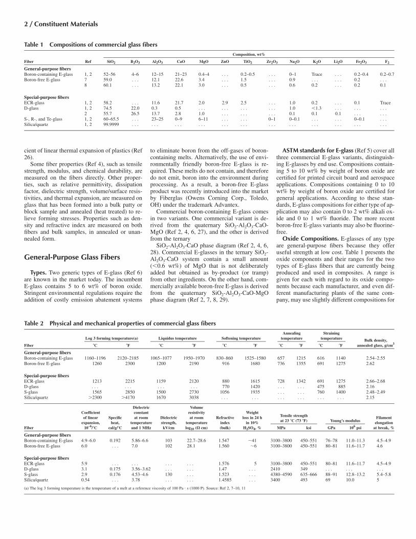
Table 1 gives compositions and Table 2 givesphysical and mechanical properties of commer-cial glass fibers.
General-purpose glass fibers (E-glass vari-ants) are discussed in the following section ofthis article, which provides an in-depth discus-
sion of compositions, melt properties, fiber prop-erties (Ref 12), methods of manufacture, and sig-nificant product types. An in-depth discussion ofcomposite applications can be found in other ar-ticles in this Volume.
Glass fibers and fabrics are used in ever in-creasing varieties for a wide range of applica-tions (Ref 13). A data book is available (Ref 14)that covers all commercially available E-glass fi-bers, whether employed for reinforcement, filtra-tion, insulation, or other applications. It lists allmanufacturers, their sales offices, agents, subsid-iaries, and affiliates, complete with addresses,and telephone and fax numbers. And it tabulateskey properties and relevant supply details of allE-glass fiber grades, that are available in themarket today.
Special-Purpose Glass Fibers. S-glass, D-glass, A-glass, ECR-glass, ultrapure silica fibers,hollow fibers, and trilobal fibers are special-pur-pose glass fibers. Selected special-purpose glassfibers are discussed in the subsequent section ofthis article. That section reviews compositions,manufacture, properties, and applications to anextent commensurate with their commercial use(Ref 15).
A companion data book (Ref 16) is availablethat covers all commercially available high-strength glass fibers including S-glass and, allsilica or quartz glass fibers, including Astro-quartz and Quartzel. It also lists a wide range ofwoven fabrics, that are commercially availablein the market of today, ranging from S-glass/ar-amid, S-glass/carbon, silica/aramid, and silica/carbon yarns to silica/boron yarns. In addition,it covers all commercially available carbon, ce-ramic, boron, and high-temperature polymer fi-bers and yarns. This data book also lists all yarncounts, fabric constructions, fabric weights, andcommercial sources.
ASTM Test Methods. ASTM has publishedstandard test methods for glass density (Ref 17),alternating current loss characteristics and di-electric constant (Ref 18), direct current conduc-tance of insulating materials (Ref 19), dielectricbreakdown voltage and dielectric strength (Ref20), softening point of glass (Ref 21), annealingpoint and strain point of glass by fiber elongation(Ref 22), annealing point and strain point ofglass by beam bending (Ref 23), viscosity (Ref24), liquidus temperature (Ref 25), and coeffi-
2 / Constituent Materials
Table 1 Compositions of commercial glass fibers
Composition, wt%
Fiber Ref SiO2 B2O3 Al2O3 CaO MgO ZnO TiO2 Zr2O3 Na2O K2O Li2O Fe2O3 F2
General-purpose fibersBoron-containing E-glass 1, 2 52–56 4–6 12–15 21–23 0.4–4 . . . 0.2–0.5 . . . 0–1 Trace . . . 0.2–0.4 0.2–0.7Boron-free E-glass 7 59.0 . . . 12.1 22.6 3.4 . . . 1.5 . . . 0.9 . . . . . . 0.2 . . .
8 60.1 . . . 13.2 22.1 3.0 . . . 0.5 . . . 0.6 0.2 . . . 0.2 0.1
Special-purpose fibersECR-glass 1, 2 58.2 . . . 11.6 21.7 2.0 2.9 2.5 . . . 1.0 0.2 . . . 0.1 TraceD-glass 1, 2 74.5 22.0 0.3 0.5 . . . . . . . . . . . . 1.0 �1.3 . . . . . . . . .
2 55.7 26.5 13.7 2.8 1.0 . . . . . . . . . 0.1 0.1 0.1 . . . . . .S-, R-, and Te-glass 1, 2 60–65.5 . . . 23–25 0–9 6–11 . . . . . . 0–1 0–0.1 . . . . . . 0–0.1 . . .Silica/quartz 1, 2 99.9999 . . . . . . . . . . . . . . . . . . . . . . . . . . . . . . . . . . . .
cient of linear thermal expansion of plastics (Ref26).
Some fiber properties (Ref 4), such as tensilestrength, modulus, and chemical durability, aremeasured on the fibers directly. Other proper-ties, such as relative permittivity, dissipationfactor, dielectric strength, volume/surface resis-tivities, and thermal expansion, are measured onglass that has been formed into a bulk patty orblock sample and annealed (heat treated) to re-lieve forming stresses. Properties such as den-sity and refractive index are measured on bothfibers and bulk samples, in annealed or unan-nealed form.
General-Purpose Glass Fibers
Types. Two generic types of E-glass (Ref 6)are known in the market today. The incumbentE-glass contains 5 to 6 wt% of boron oxide.Stringent environmental regulations require theaddition of costly emission abatement systems
to eliminate boron from the off-gases of boron-containing melts. Alternatively, the use of envi-ronmentally friendly boron-free E-glass is re-quired. These melts do not contain, and thereforedo not emit, boron into the environment duringprocessing. As a result, a boron-free E-glassproduct was recently introduced into the marketby Fiberglas (Owens Corning Corp., Toledo,OH) under the trademark Advantex.
Commercial boron-containing E-glass comesin two variants. One commercial variant is de-rived from the quaternary SiO2-Al2O3-CaO-MgO (Ref 2, 4, 6, 27), and the other is derivedfrom the ternary
SiO2-Al2O3-CaO phase diagram (Ref 2, 4, 6,28). Commercial E-glasses in the ternary SiO2-Al2O3-CaO system contain a small amount(�0.6 wt%) of MgO that is not deliberatelyadded but obtained as by-product (or tramp)from other ingredients. On the other hand, com-mercially available boron-free E-glass is derivedfrom the quaternary SiO2-Al2O3-CaO-MgOphase diagram (Ref 2, 7, 8, 29).
ASTM standards for E-glass (Ref 5) cover allthree commercial E-glass variants, distinguish-ing E-glasses by end use. Compositions contain-ing 5 to 10 wt% by weight of boron oxide arecertified for printed circuit board and aerospaceapplications. Compositions containing 0 to 10wt% by weight of boron oxide are certified forgeneral applications. According to these stan-dards, E-glass compositions for either type of ap-plication may also contain 0 to 2 wt% alkali ox-ide and 0 to 1 wt% fluoride. The more recentboron-free E-glass variants may also be fluorine-free.
Oxide Compositions. E-glasses of any typeare general-purpose fibers because they offeruseful strength at low cost. Table 1 presents theoxide components and their ranges for the twotypes of E-glass fibers that are currently beingproduced and used in composites. A range isgiven for each with regard to its oxide compo-nents because each manufacturer, and even dif-ferent manufacturing plants of the same com-pany, may use slightly different compositions for
Table 2 Physical and mechanical properties of commercial glass fibers
Log 3 forming temperature(a) Liquidus temperature Softening temperatureAnnealing
temperatureStraining
temperature Bulk density,Fiber �C �F �C �F �C �F �C �F �C �F annealed glass, g/cm3
General-purpose fibersBoron-containing E-glass 1160–1196 2120–2185 1065–1077 1950–1970 830–860 1525–1580 657 1215 616 1140 2.54–2.55Boron-free E-glass 1260 2300 1200 2190 916 1680 736 1355 691 1275 2.62
Special-purpose fibersECR-glass 1213 2215 1159 2120 880 1615 728 1342 691 1275 2.66–2.68D-glass . . . . . . . . . . . . 770 1420 . . . . . . 475 885 2.16S-glass 1565 2850 1500 2730 1056 1935 . . . . . . 760 1400 2.48–2.49Silica/quartz �2300 �4170 1670 3038 . . . . . . . . . . . . . . . . . . 2.15
Coefficientof linear
expansion,Specific
heat,
Dielectricconstantat room
temperatureDielectricstrength,
Volumeresistivityat room
temperatureRefractive
index
Weightloss in 24 h
in 10%
Tensile strengthat 23 �C (73 �F) Young’s modulus
Filamentelongation
Fiber 10–6/�C cal/g/�C and 1 MHz kV/cm log10 (X cm) (bulk) H2SO4, % MPa ksi GPa 106 psi at break, %
General-purpose fibersBoron-containing E-glass 4.9–6.0 0.192 5.86–6.6 103 22.7–28.6 1.547 �41 3100–3800 450–551 76–78 11.0–11.3 4.5–4.9Boron-free E-glass 6.0 . . . 7.0 102 28.1 1.560 �6 3100–3800 450–551 80–81 11.6–11.7 4.6
Special-purpose fibersECR-glass 5.9 . . . . . . . . . . . . 1.576 5 3100–3800 450–551 80–81 11.6–11.7 4.5–4.9D-glass 3.1 0.175 3.56–3.62 . . . . . . 1.47 . . . 2410 349 . . . . . . . . .S-glass 2.9 0.176 4.53–4.6 130 . . . 1.523 . . . 4380–4590 635–666 88–91 12.8–13.2 5.4–5.8Silica/quartz 0.54 . . . 3.78 . . . . . . 1.4585 . . . 3400 493 69 10.0 5
(a) The log 3 forming temperature is the temperature of a melt at a reference viscosity of 100 Pa • s (1000 P). Source: Ref 2, 7–10, 11

Glass Fibers / 3
the same glass. These variations result mainlyfrom differences in the available glass batch (rawmaterials). Tight control is maintained within agiven production facility to optimize composi-tional consistency and maximize production ef-ficiencies.
As shown in Table 1, commercial, boron-con-taining E-glass compositions (Ref 1, 2, 4, 6, 12,24) differ substantially from boron-free E-glasscompositions. The silica content for commercialboron-containing E-glasses ranges from 52 to 56wt% by weight, and for commercial boron-freeE-glasses from 59 to 61 wt%. The alumina con-tent generally ranges from 12 to 15 wt% for theseboron-containing E-glasses and from 12 to 13.5wt% for these boron-free E-glasses. The calciacontent ranges from 21 to 23 wt% for these com-mercial boron-containing E-glasses and from 22to 23 wt% for these boron-free E-glasses.
For commercial, boron-containing, ternary orquaternary E-glasses, the magnesia contentranges from 0.4 wt% (tramp only) to greateramounts if magnesia (dolomite) is deliberatelyadded. For commercial boron-free E-glasses, itranges from 3.1 to 3.4 wt% (see Table 1). Theboron oxide content ranges from 5 to 6% forcommercial boron-containing E-glasses, and it iszero for boron-free E-glasses. The titania contentranges from 0.4 to 0.6 wt% for commercial bo-ron-containing E-glasses. For boron-free E-glasses, it ranges from 0.5 wt% (Ref 8) to 1.5wt% (Ref 7) (see also Table 1).
Environmentally friendly E-glass melts areboron-free and fluorine-free. However, the log 3fiber forming or fiberization temperature (TF) ofboron-free E-glass melts may be as much as 100to 110 �C (180 to 200 �F) higher than that ofboron-containing E-glass melts (Fig. 1). The log3 forming temperature is the temperature of amelt at a reference viscosity of 100 Pa • s (1000P). In addition, the softening point of boron-freeE-glass is 60 to 90 �C (110 to 160 �F) higher alsothan that of a boron-containing E-glass. Thehigher process temperature requires more pro-cess energy, but the higher softening point fa-cilitates higher use temperatures.
Melt Properties. According to Table 2, thelog 3 forming temperature, TF, of boron-contain-ing E-glasses ranges from 1140 to 1185 �C (2085to 2165 �F). The liquidus temperature (TL) is thetemperature below which solid (crystals) willform. It ranges form 1050 to 1064 �C (1920 to1945 �F). The difference between forming andliquidus temperature (DT) ranges from 81 to 90�C (146 to 162 �F). In contrast, the log 3 fiberforming temperature of boron-free E-glassesranges from 1250 to 1264 �C (2280 to 2307 �F),the liquidus temperature from 1146 to 1180 �C(2095 to 2155 �F), and the difference betweenforming and liquidus temperature (DT) from 86to 104 �C (155 to 187 �F) (Ref 7–10). Finally,the softening point of boron-containing E-glasses ranges from 830 to 860 �C (1525 to 1580�F); that of boron-free E-glasses is about 916 �C(1680 �F).
Mechanical Properties. Table 2 also com-pares the mechanical properties of the boron-free
and boron-containing E-glasses. Elastic modulus(or fiber stiffness) of boron-free E-glasses isabout 5% higher than that of boron-containingE-glasses, while pristine, virgin, or single-fila-ment tensile strength is said to be about the samefor both types of E-glasses when both are testedat room temperature (Ref 8, 9).
Physical Properties. In addition, Table 2compares the physical properties of the boron-free and boron-containing E-glasses. Most im-portantly, the corrosion resistance of boron-freeE-glasses was found to be seven times higherthan that of boron-containing E-glasses whentested at room temperature for 24 h in 10% sul-furic acid. It approaches that of ECR glass fibers(Ref 9, 10).
Boron-free E-glasses have a slightly higherdensity (2.62 g/cm3) than boron-containing E-glasses (2.55 g/cm3), but the density of both fi-bers is lower than that of ECR glass (2.66 to 2.68g/cm3), a corrosion-resistant special-purpose fi-ber. Boron-free E-glasses have a higher refrac-tive index and linear expansion coefficient thanboron-containing E-glass fibers. The refractiveindex of both E-glasses is lower than that of ECRglass. The linear expansion coefficient of ECRglass fibers is midway between that of the twoE-glasses.
Boron-free E-glasses have a slightly higher di-electric constant (7.0) than boron-containing E-glasses (5.9 to 6.6) when measured at room tem-perature and at a frequency of 1 MHz. As aresult, boron-containing, but not boron-free, E-glass fibers are needed for electronic circuitboards and aerospace applications. On the otherhand, boron-free and boron-containing E-glassfibers are used in structural composites where thedielectric constant is of no concern. Compositeand laminate uses of all glass fibers are discussedin other articles in this Volume.
Special-Purpose Glass Fibers
Types. Special-purpose fibers, which are ofcommercial significance in the market today, in-clude glass fibers with high corrosion resistance(ECR-glass), high strength (S-, R-, and Te-glass), with low dielectric constants (D-glass),high strength fibers, and pure silica or quartz fi-bers, which can be used at ultrahigh tempera-tures. These fibers will be discussed in the fol-lowing paragraphs. Others special-purpose fibersinclude A-glass, C-glass, hollow fibers, bicom-ponent fibers, and trilobal fibers. These special-purpose glass fibers have recently been reviewedin detail (Ref 2).
ECR-Glass. The corrosion resistance of glassfibers is determined by their chemical structure.It has already been noted in the preceding sec-tion on general-purpose glass fibers that boron-free E-glass fibers derived from the quaternarySiO2-Al2O3-CaO-MgO phase diagram havehigher acid resistance than E-glass fibers thatare derived from the ternary SiO2-Al2O3-CaOphase diagram but have high boron levels. TheECR glass fibers offer enhanced long-term
acid resistance and short-term alkali resistance(Ref 27).
The addition of high levels of ZnO and TiO2
to the boron-free quaternary E-glass system fur-ther enhances the corrosion resistance of the re-sulting ECR glass fibers while at the same timereducing the log 3 forming temperature. Theproduct and process advantage are obtained at acost penalty. About 2% ZnO and two additionalpercent TiO2 are required, and both materials areknown to be costly batch ingredients.
S-Glass, R-Glass, and Te-Glass. The tensilestrength of glass fibers is determined by thestructure connectivity of the silicate network, no-tably, by the absence of alkali oxides, which arenot readily integrated into the structure. Thestructure of boron oxide, though being a part ofthe network, is weaker than that of silicon oxide,and therefore, boron oxide serves as a flux. Sev-eral high-strength glass fibers are known, includ-ing S-glass, Te-glass, and R-glass (Ref 2). Alloffer 10 to 15% higher strength than E-glass atroom temperature, but their real value is theirability to withstand higher in-use temperaturesthan E-glass. These fibers are used in militaryapplications. Stringent quality-control proce-dures are necessary to meet military specifica-tions.
S-glass and Te-glass are derivatives of the ter-nary SiO2-Al2O3-CaO system. R-glass is a de-rivative of the quaternary SiO2-Al2O3-CaO-MgO system. S-glass and S-2 glass fibers, aproduct variant, have the same glass composition(Ref 2) but different coatings. While internalstructural uniformity (high strength) is achievedwith these boron-free and alkali-free composi-tions, their forming temperatures are higher thanthat of E-glass. Attainment of high in-use tem-peratures is a definite product advantage, but
Vis
cosi
ty, l
og p
oise
Boron-free E-glass
Boron-containing E-glass
5.5
5.0
4.5
4.0
3.5
3.0
2.5
2.0
1.5
1800 2000 2200 2400 2600
Temperature, °F
Temperature, °C
900 1000 1100 1200 1300 1400 1500
Fig. 1 Viscosity of boron-free and boron-containing E-glass

4 / Constituent Materials
higher melt temperatures, more process energy,and more costly bushing alloys are required.
Silica/Quartz Fibers. Glass fibers with in-creasing SiO2 levels can be used in applicationsrequiring increasingly high in-use temperatures.High-silica fibers (95% SiO2) are amorphousglass fibers. They are obtained by acid leachingof borosilicate E-glass fabrics, which are, in turn,used as insulation blankets at temperatures up to1040 �C (1900 �F). Pure silica fibers (99% SiO2)are made by dry spinning from aqueous water-glass solutions. They are known by the traden-ame “Silfa” and mostly are used as yarns, forexample, for wire insulation at temperatures upto 1090 �C (1990 �F). For details see Ref 2. Theyare not used in composite applications and aretherefore not shown in Table 2.
Ultrapure silica glass fibers or quartz fibers(99.99% SiO2), which are down-drawn from pre-forms (Ref 2) in a containerless process, are alsoamorphous, despite the fact that the trivial name“quartz” or trade names Quartzel and Astro-quartz would imply the presence of the hexag-onal crystal structure of quartz. Ultrapure silica(quartz) fibers combine superior high-tempera-ture resistance with superior transparency to ul-traviolet (UV) and longer wavelength radiation.For example, in a composite radome on the noseof an aircraft, they protect delicate radar equip-ment from flying objects, lightning and staticdischarge (Ref 30). The purest of all commercialsilica glass or quartz fibers (99.999% SiO2) areobtained by dry-spinning of a reagent grade te-traethylorthosilicate sol-gel (Ref 2).
All ultrapure silica glass or quartz fibers areused in yarn and in composite applications andare, therefore, shown in Table 2. Ultrapure andpure silica yarns and fabrics can be used at tem-peratures up to 1090 �C (1990 �F), high silicafabrics at up to 1040 �C (1900 �F), and S-glass,Te-glass, and R-glass yarns and fabrics at up to815 �C (1500 �F) (for process and product detailssee Ref 2).
D-Glass. The electrical properties of glass fi-bers are determined by their volume resistivity,surface conductivity, dielectric constant and losstangent (Ref 2). E-glass with its relatively highdielectric constant is the major reinforcing fiberfor printed circuit board (PCB) laminates in themarket today, but miniaturization drives the in-dustry toward specialty fibers with lower dielec-tric constants and lower dielectric loss tangents.
Several low D-glass variants are known. Allhave very high B2O3 levels (20 to 26%) and,therefore, much lower dielectric constants thanE-glass (4.10 to 3.56 versus 6.86 to 7.00). ThoseD-glass variants having low dielectric loss tan-gents as well (Ref 8) are said to offer the highestvalue in-use when used to reinforce PCB lami-nates. Because of their high cost, however, anyD-glass version will remain a low volume spe-cialty fiber. The very high boron-oxide levels,which are needed and in part emitted from themelt, may require an entirely different specialtyprocess (see Ref 2 for details).
For very different reasons, ultrapure silica fi-bers, hollow E-glass fibers, S-glass, and other
high-temperature fibers have lower dielectricconstants than solid E-glass. They, too, can andare being used to reinforce printed circuit board(PCB) laminates. However, silica fibers have alow modulus and are, therefore, less effective asreinforcing fibers. Hollow fibers, although ini-tially effective because of their low dielectricconstant, lose their dielectric properties if mois-ture can seep into the laminate structure.
Glass Melting and Fiber Forming
A glass is an amorphous solid obtained bycooling a melt (i.e., liquid phase) sufficiently fastthat crystallization (devitrification) cannot occur.When the melt is cooled slowly, crystallizationcan occur at the liquidus temperature, TL, wherecrystals and melt are in equilibrium, or below.Glass fibers are therefore obtained at high cool-ing rates. Chemically, a glass consists of a silicanetwork. Other oxides facilitate melting, homog-enizing, removal of gaseous inclusions, and fiberformation at optimum temperatures. This sectionaddresses the generic glass-melting and fiber-forming process, including the viscosity versustemperature profile that is required for general-purpose E-glass glass fibers and, more specifi-cally, for E-glass fibers containing 5 to 6% boronoxide (see Ref 1 for details).
Depending on fiber diameter, optimum fiberformation is achieved with melts having a vis-cosity ranging from log 2.5 to log 3 P. The ge-neric melting and forming process that is re-quired for boron-free E-glass is the same as thatrequired for boron-containing E-glass, but theviscosity/temperature profile differs. The relativeforming temperatures can be deduced from theFulcher curves shown in Fig. 1. They will beproportionately higher for boron-free E-glass atequal melt viscosities between log 2.5 to log 3.0P. This section does not address the glass meltingand fiber forming processes required for the spe-cial-purpose glass fibers, that is, ECR-glass, S-
glass, ultrapure silica fibers, and D-glass (seeRef 2).
Batch Mixing and Melting. The glass melt-ing process begins with the weighing and blend-ing of selected raw materials. In modern fiber-glass plants, this process is highly automated,with computerized weighing units and enclosedmaterial transport systems. The individual com-ponents are weighed and delivered to a blendingstation where the batch ingredients are thor-oughly mixed before being transported to thefurnace.
Fiberglass furnaces generally are divided intothree distinct sections (Fig. 2). Batch is deliveredinto the furnace section for melting, removal ofgaseous inclusions, and homogenization. Then,the molten glass flows into the refiner section,where the temperature of the glass is loweredfrom 1370 �C (2500 �F) to about 1260 �C (2300�F). The molten glass next goes to the forehearthsection located directly above the fiber-formingstations. The temperatures throughout this pro-cess are prescribed by the viscosity characteris-tics of the particular glass. In addition, the physi-cal layout of the furnace can vary widely,depending on the space constraints of the plant.
Fiberizing and Sizing. The conversion ofmolten glass in the forehearth into continuousglass fibers is basically an attenuation process(Fig. 3). The molten glass flows through a plat-inum-rhodium alloy bushing with a large num-ber of holes or tips (400 to 8000, in typical pro-duction). The bushing is heated electrically, andthe heat is controlled very precisely to maintaina constant glass viscosity. The fibers are drawndown and cooled rapidly as they exit the bush-ing.
A sizing is then applied to the surface of thefibers by passing them over an applicator thatcontinually rotates through the sizing bath tomaintain a thin film through which the glass fil-aments pass. It is this step, in addition to theoriginal glass composition, which primarily dif-ferentiates one fiberglass product from another.
Fig. 2 Furnace for glass melting

Glass Fibers / 5
The components of the sizing impart strand in-tegrity, lubricity, resin compatibility, and adhe-sion properties to the final product, thus tailoringthe fiber properties to the specific end-use re-quirements. After applying the sizing, the fila-ments are gathered into a strand before ap-proaching the take-up device. If small bundlesof filaments (split strands) are needed, multiplegathering devices (often called shoes) are used.
Fiber Diameters. The attenuation rate, andtherefore the final filament diameter, is con-
trolled by the take-up device. Fiber diameter isalso affected by bushing temperature, glass vis-cosity, and the pressure head over the bushing.The most widely used take-up device is theforming winder, which employs a rotating colletand a traverse mechanism to distribute the strandin a random manner as the forming packagegrows in diameter. This facilitates strand re-moval from the package in subsequent process-ing steps, such as roving or chopping. The form-ing packages are dried and transferred to the
specific fabrication area for conversion into thefinished fiberglass roving, mat, chopped strand,or other product.
In recent years, processes have been devel-oped to produce finished roving or choppedproducts directly during forming, thus leading tothe term direct draw roving or direct choppedstrand. Special winders and choppers designedto perform in the wet-forming environment areused in these cases (Fig. 4).
Yarn Nomenclature. It is standard practicein the fiberglass industry to refer to a specificfilament diameter by a specific alphabet desig-nation, as listed in Table 3. Fine fibers, which areused in textile applications, range from Dthrough G. One reason for using fine fibers is toprovide enough flexibility to the yarn to enableit to be processed in high-speed twisting andweaving operations. Conventional plastics rein-forcement, however, uses filament diameters thatrange from G to T.
Important Commercial Products
Once the continuous glass fibers have beenproduced they must be converted into a suitableproduct form for their intended composite ap-plication. The major finished forms for E-glassfibers are continuous roving, woven roving, fi-berglass mat, chopped strand, and yarns for tex-tile applications.
Fiberglass roving is produced by collecting abundle of strands into a single large strand,which is wound into a stable, cylindrical pack-age. This is called a multiend roving process.The process begins by placing a number of oven-dried forming packages into a creel. The endsare then gathered together under tension and col-lected on a precision roving winder that has aconstant traverse-to-winding ratio, and is calledthe waywind. This ratio has a significant effecton package stability, strand characteristics, andease of payout in subsequent operations. Theyield (meter per kilogram, or yard per pound) ofthe finished roving is determined by the numberof input ends and the yield of the input strand orsliver. Final package weight and dimensions canbe made to vary widely, depending upon the re-quired end-use. Figure 4 shows the entire pro-cess.
Rovings are used in many applications. Whenused in a spray-up fabrication process, the rovingis chopped with an air-powered gun that propelsthe chopped-glass strands to a mold while si-multaneously applying resin and catalyst in thecompact ratio. This process is commonly usedfor bath tubs, shower stalls, and many marineapplications. In another important process, theproduction of sheet molding compound (SMC),the roving is chopped onto a bed of formulatedpolyester resin and compacted into a sheet,which thickens with time. This sheet is thenplaced in a press and molded into parts. Manyfiber-reinforced plastic (FRP) automotive bodypanels are made by this process.
Fig. 3 Fiberglass forming process
Fig. 4 Multiend roving process production

6 / Constituent Materials
Filament winding and pultrusion are processesthat use single-end rovings in continuous form.Applications include pipes, tanks, leaf springs,and many other structural composites. In theseprocesses the roving is passed through a liquidresin bath and then shaped into a part by windingthe resin-impregnated roving onto a mandrel orby pulling it through a heated die. Because of aproperty called catenary (the presence of somestrands that have a tendency to sag within a bun-dle of strands), multiend rovings sometimes donot process efficiently. Catenary is caused by un-even tension in the roving process that results inpoor strand integrity.
While providing desirable entanglement fortransverse strength in pultrusion, the looser endsin the roving may eventually cause loops andbreakouts in close-tolerance orifices, making re-inforced plastics processing difficult. Conse-quently, the process of direct forming single-endrovings was developed by using very large bush-ings and a precision winder specially designedto operate in the severe forming environment.No subsequent step other than drying is required.Single-end rovings have become the preferredproduct for many filament-winding and pultru-sion applications.
Woven roving is produced by weaving fiber-glass rovings into a fabric form. This yields acoarse product that is used in many hand lay-upand panel molding processes to produce FRPs.Many weave configurations are available, de-pending on the requirements of the laminate.Plain or twill weaves provide strength in bothdirections, while a unidirectionally stitched orknitted fabric provides strength primarily in onedimension. Many novel fabrics are currentlyavailable, including biaxial, double-bias, and tri-axial weaves for special applications.
Fiberglass mats may be produced as eithercontinuous- or chopped-strand mats. A chopped-strand mat is formed by randomly depositingchopped fibers onto a belt or chain and bindingthem with a chemical binder, usually a thermo-plastic resin with a styrene solubility ranging
from low to high, depending on the application.For example, hand lay-up processes used tomoderate corrosion-resistant liners or boat hullsrequire high solubility, whereas closed-moldprocesses such as cold press or compressionmolding require low solubility to prevent wash-ing in the mold during curing.
Continuous-strand mat is formed in a similarmanner but without chopping, and, usually, lessbinder is required because of increased mechan-ical entanglement, which provides some inherentintegrity. Continuous-strand mat may be used inclosed mold processes and as a supplementalproduct in unidirectional processes such as pul-trusion, where some transverse strength is re-quired. A number of specialty mats are also pro-duced. Surfacing veil made with C-glass is usedto make corrosion-resistant liners for pipes andtanks. Surfacing veils made from other glasscompositions are used to provide a smooth fin-ished surface in some applications. Glass tissueis used in some vinyl flooring products.
Combinations of a mat and woven rovinghave been developed for specific products in re-cent years. In many lay-up processes the lami-nate is constructed from alternate layers of fi-berglass mat and woven roving. Fiberglassproducers thus began to provide products thatmake this process more efficient. The appropri-ate weights of fiberglass mat (usually chopped-strand mat) and woven roving are either boundtogether with a chemical binder or mechanicallyknit or stitched together. This product can thenbe used as a significant labor saver by the fab-ricators.
Chopped strand products are produced bytwo major processes. In the first process, driedforming packages are used as a glass source. Anumber of strand ends are fed into a chopper,which chops them into the correct length, typi-cally 3.2 to 12.7 mm (
18 to
12 in.). The product
is then screened to remove fuzz and contami-nation and boxed for shipment (Fig. 5). The sec-ond process, used in recent years to producemany chopped-strand products, is the direct-chop process. In this process, large bushings areused in forming, and the strands are chopped ina wet state directly after sizing is applied. Thewet, chopped strands are then transported to an
area where they are dried, screened, and pack-aged. The direct-chop process has provided theindustry with a wide variety of chopped rein-forcements for compounding with resins.
Chopped glass is widely used as a reinforce-ment in the injection molding industry. The glassand resin may be dry blended or extrusion com-pounded in a preliminary step before molding,or the glass may be fed directly into the moldingmachine with the plastic resin. Hundreds of dif-ferent parts for many applications are made inthis manner. Chopped glass may also be used asa reinforcement in some thermosetting applica-tions, such as bulk molding compounds.
Milled fibers are prepared by hammer millingchopped or sawed continuous strand glass fibers,followed by chemically sizing for some specificapplications and by screening to length. Fiberlengths typically vary from particulates to screenopening dimensions for the reported nominallength (0.79 to 6.4 mm, or
132 to
14 in.). As
such, milled fibers have a relatively low aspectratio (length to diameter). They provide someincreased stiffness and dimensional stability toplastics but minimal strength. Their use is pri-marily in phenolics, reaction-injection moldedurethanes, fluorocarbons, and potting com-pounds.
Fiberglass paper is the reinforcing elementfor fiberglass roofing shingles. Chopped strandsof 25 to 50 mm (1 to 2 in.) length are usuallyused in making fiberglass paper or a thin fiber-glass mat. In this process, chopped fibers are dis-persed in water to form a dilute solution. Thefiberglass strands filamentize during the mixingand dispersion process. The solution is pumpedonto a continuously moving chain, where mostof the water is removed by vacuum, leaving be-hind a uniformly distributed, thin fiberglass mat.A binding resin is added on-line, followed bydrying and curing, to form the fiberglass paper.This paper is then combined with the appropriateresin system to form roofing shingles.
Textile yarns are fine-fiber strands of yarnfrom the forming operation that are air dried onthe forming tubes to provide sufficient integrityto undergo a twisting operation. Twist providesadditional integrity to yarn before it is subjectedto the weaving process, a typical twist consisting
Table 3 Filament diameter nomenclature
Filament diameter
Alphabet lm 10–4 in.
AA 0.8–1.2 0.3–0.5A 1.2–2.5 0.5–1.0B 2.5–3.8 1.0–1.5C 3.8–5.0 1.5–2.0D 5.0–6.4 2.0–2.5E 6.4–7.6 2.5–3.0F 7.6–9.0 3.0–3.5G 9.0–10.2 3.5–4.0H 10.2–11.4 4.0–4.5J 11.4–12.7 4.5–5.0K 12.7–14.0 5.0–5.5L 14.0–15.2 5.5–6.0M 15.2–16.5 6.0–6.5N 16.5–17.8 6.5–7.0P 17.8–19.0 7.0–7.5Q 19.0–20.3 7.5–8.0R 20.3–21.6 8.0–8.5S 21.6–22.9 8.5–9.0T 22.9–24.1 9.0–9.5U 24.1–25.4 9.5–10
Fig. 5 Chopped-strand production

Glass Fibers / 7
of up to one turn per inch. The twisting operationis shown in Fig 6. In many instances, heavieryarns are needed for the weaving operation. Thisis normally accomplished by twisting togethertwo or more single strands, followed by a plyingoperation. Plying essentially involves retwistingthe twisted strands in the opposite direction fromthe original twist. The two types of twist nor-mally used are known as S and Z, which indicatethe direction in which the twisting is done. Usu-ally, two or more strands twisted together withan S twist are plied with a Z twist in order togive a balanced yarn. Thus, the yarn properties,such as strength, bundle diameter, and yield, canbe manipulated by the twisting and plying opera-tions.
The yarn nomenclature for fiberglass yarnsconsists of both letters of the alphabet and num-bers. For instance, in ECG 75 2/4:
● The first letter specifies the glass composi-tion, in this case, E-glass.
● The second letter specifies the filament type(staple, continuous, texturized) (in the case,of ECG 75 2/4, continuous).
● The third letter specifies the filament diameter(in this case, G).
● The next series of numbers represents the ba-sic strand yield in terms of
1100 th of the
yield (in this case, 75 means 7500 yd/lb).● The fraction represents the number of strands
twisted together (numerator) to form a singleend and the number of such ends plied to-gether (denominator) to form the final yarn.In the above case, 2/4 means two basicstrands are twisted together to form a singleend, and four such ends are plied together(usually in the opposite direction) to form thefinal yarn.
The product brochures from various weavers aswell as to Ref 4 should be consulted for detailson commercially available fabrics. The Glass-Fibre Dictionary and Databook (Ref 14) shouldbe consulted for even greater detail and/or for asummary of all commercially available yarns.
Fiberglass Fabric. Fiberglass yarns are con-verted to fabric form by conventional weavingoperations. Looms of various kinds are used inthe industry, but the air jet loom is the most pop-ular. The major characteristics of a fabric includeits style or weave pattern, fabric count, and theconstruction of warp yarn and fill yarn. Together,these characteristics determine fabric propertiessuch as drapability and performance in the finalcomposite. The fabric count identifies the num-ber of warp and fill yarns per inch. Warp yarnsrun parallel to the machine direction, and fillyarns are perpendicular.
There are basically four weave patterns: plain,basket, twill, and satin. Plain weave is the sim-plest form, in which one warp yarn interlacesover and under one fill yarn. Basket weave hastwo or more warp yarns interlacing over and un-der two or more fill yarns. Twill weave has oneor more warp yarns floating over at least two fillyarns. Satin weave (crowfoot) consists of onewarp yarn interfacing over three and under onefill yarn to give an irregular pattern in the fabric.The eight-harness satin weave is a special case,in which one warp yarn interlaces over seven andunder one fill yarn to give an irregular pattern.In fabricating a composite part, the satin weavegives the best conformity to complex contours,followed in descending order by twill, basket,and plain weaves.
Texturized Yarn. Texturizing is a process inwhich the textile yarn is subjected to an air jetthat impinges on its surface to make the yarn’fluffy’’ (Fig. 7). The air jet causes the surfacefilaments to break at random, giving the yarn abulkier appearance. The extent to which this oc-curs can be controlled by the velocity of the airjet and the yarn feed rate. The texturzing processallows the resin-to-glass ratio to be increased inthe final composite. One of the major applica-tions of texturized yarns is as an asbestos re-placement.
Carded Glass Fibers. Carding is a processthat makes a staple fiberglass yarn from contin-uous yarn. The continuous yarn is chopped into38 to 50 mm (1.5 to 2.0 in.) lengths, and thenaligned in one direction in a mat form. It is fi-nally converted to a staple yarn. The yarn pro-duced by this process can absorb much moreresin than texturized yarn. Carded glass fibers arealso used as an asbestos replacement in frictionapplications, such as automotive brake linings.
REFERENCES
1. K.L. Loewenstein, The ManufacturingTechnology of Continuous Glass Fibers, 3rdrevised ed., Elsevier, 1993
2. F.T. Wallenberger, Structural Silicate andSilica Glass Fibers, in Advanced InorganicFig. 7 Texturizing
Fig. 6 Twisting

8 / Constituent Materials
Fibers Processes, Structures, Properties,Applications, F.T. Wallenberger, Ed., Klu-wer Academic Publishers, 1999, p 129–168
3. F.T. Wallenberger, Melt Viscosity and Mod-ulus of Bulk Glasses and Fibers: Challengesfor the Next Decade, in Present State andFuture Prospects of Glass Science and Tech-nology, Proc. of the Norbert Kreidl Sym-posium (Triesenberg, Liechtenstein), 1994,p 63–78
4. D.M. Miller, Glass Fibers, Composites, Vol1, Engineered Materials Handbook, ASMInternational, 1987, p 45–48
5. “Standard Specification for Glass FiberStrands”, D 578-98, Annual Book of ASTMStandards, ASTM
6. P.K. Gupta, Glass Fibers for Composite Ma-terials, Fibre Reinforcements for CompositeMaterials, A.R. Bunsell, Ed., Elsevier Pub-lishers, 1988, p 19–72
7. J.F. Sproull, Fiber Glass Composition, U.S.Patent 4,542,106, 17 Sept 1985
8. W.L. Eastes, D.A. Hofman, and J.W. Win-gert, Boron-Free Glass Fibers, U.S. Patent5,789,329, 4 Aug 1998
9. “Advantex Glass Fiber, A New Era in Com-posites Technology—Systems Thinking”,Product Bulletin, Owens Corning, 1998
10. F. Rossi and G. Williams, A New Era inGlass Fiber Composites, Proc., 28th AVKConf. (Baden-Baden, Germany), 1-2 Oct1997, p 1–10
11. O.V. Mazurin, M.V. Streltsina and T.P.Shvaiko-Shvaikovskaya, Viscosity of Silica,
Handbook of Glass Data, Part A, Elsevier,1983, p 75
12. P.F. Aubourg and W.W. Wolf, “Glass Fibers-Glass Composition Research,” presented atGlass Division Meeting (Grossinger, NY),American Ceramic Society, Oct 1984
13. J.C. Watson and N. Raghupathi, Glass Fi-bers, in Composites, Vol 1, Engineered Ma-terials Handbook, ASM International, 1987,p 107–111
14. T.F. Starr, Glass-Fibre Dictionary and Da-tabook, 2nd ed., Chapman & Hall, 1997
15. W.W. Wolf and S.L. Mikesell, Glass Fibers,Encyclopedia of Materials Science and En-gineering, 1st Edition, 1986
16. F.T. Starr, Carbon and High Performance Fi-bres, Directory and Databook, ed. 6, Chap-man & Hall, 1995
17. “Standard Test Method for Density of Glassby Buoyancy,” C 693, Annual Book ofASTM Standards, ASTM
18. “Standard Test Methods for A-C Loss Char-acteristics and Permittivity (Dielectric Con-stant) of Solid Electrical Insulating Materi-als,” D 150, Annual Book of ASTMStandards, ASTM
19. “Standard Test Methods for D-C Resistanceor Conductance of Insulating Materials,” D257, Annual Book of ASTM Standards,ASTM
20. “Standard Test Method for Dielectric Break-down Voltage and Dielectric Strength ofSolid Electrical Insulating Materials atCommercial Power Frequencies,” D 149,Annual Book of ASTM Standards, ASTM
21. “Standard Test Method for Softening Pointof Glass,” C 338, Annual Book of ASTMStandards, ASTM
22. “Standard Test Method for Annealing Pointand Strain Point of Glass by Fiber Elonga-tion,” C 336, Annual Book of ASTM Stan-dards, ASTM
23. “Standard Test Method for Annealing Pointand Strain Point of Glass by Beam Bend-ing,” C 598, Annual Book of ASTM Stan-dards, ASTM
24. “Standard Practice for Measuring Viscosityof Glass Above the Softening Point,” C965,Annual Book of ASTM Standards, ASTM
25. “Standard Practices for Measurement of Li-quidus Temperature of Glass by the Gradi-ent Furnace Method,” C829, Annual Bookof ASTM Standards, ASTM
26. “Standard Test Method for Coefficient ofLinear Thermal Expansion of Plastics,” D696, Annual Book of ASTM Standards,ASTM
27. J.F. Dockum, Jr., Fiberglass, in Handbookof Reinforcement for Plastics, J.V. Milewskiand H.S. Katz, Ed., Van Nostrand ReinholdCompany, New York, 1987, p 233–286
28. R.A. Schoenlaub, “Glass Compositions,”U.S. Patent 2,334,961, 5 Dec, 1940
29. R.L. Tiede and F.V. Tooley, “Glass Com-position,” U.S. Patent 2,571,074, 23 Nov,1948
30. L.L. Clements, Composite Radomes Protectand Perform, High Performance Composite,September/October 2000, p 44–47

ASM International is the society for materials engineers and scientists, a worldwide network dedicated to advancing industry, technology, and applications of metals and materials. ASM International, Materials Park, Ohio, USA www.asminternational.org
This publication is copyright © ASM International®. All rights reserved. Publication title Product code ASM Handbook Volume 21: Composites 06781G
To order products from ASM International:
Online Visit www.asminternational.org/bookstore
Telephone 1-800-336-5152 (US) or 1-440-338-5151 (Outside US)
Fax 1-440-338-4634
Mail Customer Service, ASM International 9639 Kinsman Rd, Materials Park, Ohio 44073, USA
Email [email protected]
In Europe
American Technical Publishers Ltd. 27-29 Knowl Piece, Wilbury Way, Hitchin Hertfordshire SG4 0SX, United Kingdom Telephone: 01462 437933 (account holders), 01462 431525 (credit card) www.ameritech.co.uk
In Japan Neutrino Inc. Takahashi Bldg., 44-3 Fuda 1-chome, Chofu-Shi, Tokyo 182 Japan Telephone: 81 (0) 424 84 5550
Terms of Use. This publication is being made available in PDF format as a benefit to members and customers of ASM International. You may download and print a copy of this publication for your personal use only. Other use and distribution is prohibited without the express written permission of ASM International. No warranties, express or implied, including, without limitation, warranties of merchantability or fitness for a particular purpose, are given in connection with this publication. Although this information is believed to be accurate by ASM, ASM cannot guarantee that favorable results will be obtained from the use of this publication alone. This publication is intended for use by persons having technical skill, at their sole discretion and risk. Since the conditions of product or material use are outside of ASM's control, ASM assumes no liability or obligation in connection with any use of this information. As with any material, evaluation of the material under end-use conditions prior to specification is essential. Therefore, specific testing under actual conditions is recommended. Nothing contained in this publication shall be construed as a grant of any right of manufacture, sale, use, or reproduction, in connection with any method, process, apparatus, product, composition, or system, whether or not covered by letters patent, copyright, or trademark, and nothing contained in this publication shall be construed as a defense against any alleged infringement of letters patent, copyright, or trademark, or as a defense against liability for such infringement.