gl ow darren di - massachusetts institute of technology · abstract s arah dagen (mit p s fc),...
TRANSCRIPT
Glo
w D
ischarg
e Clean
ing
for L
DX
Sarah
Dag
enM
IT P
lasma S
cience an
d F
usio
n C
enter
Darren
Garn
ier and
Eu
gen
io O
rtizC
olu
mb
ia Un
iversity
Presented at the 44
th Annual M
eeting ofthe D
ivision of Plasm
a Physics
Orlando, F
lorida
Novem
ber 11-15, 2002

Ab
stract
Sarah D
agen (MIT
PS
FC
), Darren G
arnier, Eugenio O
rtiz (Colum
bia
University)
Th
e L
ev
itate
d D
ipo
le E
xp
erim
en
t (LD
X) h
as
co
mp
lete
d
desig
n o
f its g
low
dis
ch
arg
e c
lea
nin
g (G
DC
) sy
ste
m. G
DC
will
be
u
se
d
be
fore
firs
t p
las
ma
s
in L
DX
, a
s
we
ll as
be
twe
en
ex
pe
rime
nta
l op
era
tion
s, to
elim
ina
te im
pu
rities
from
the vacu
um
vessel. Th
e glo
w is created
by a m
ovab
le
ano
de p
rob
e inserted
thro
ug
h a flan
ge o
n th
e un
dersid
e of
the
ve
ss
el. T
he
an
od
e is
bia
se
d w
ith u
p t
o 8
00
V w
ith
res
pe
ct to
the
ve
ss
el w
all w
ith 1
2k
W D
C p
ow
er availab
le
for p
lasma fo
rmatio
n.

Aw
ay from
the an
od
e, a biased
tun
gsten
filamen
t will b
e
ins
talle
d to
aid
in d
isc
ha
rge
bre
ak
do
wn
an
d re
du
ce
the
like
liho
od
of a
rcin
g[1
]. Th
e fila
me
nt m
ay
als
o b
e u
se
d
for p
reio
niza
tion
du
ring
ex
pe
rime
nta
l op
era
tion
s. G
DC
will b
e im
ple
me
nte
d w
ith d
eu
teriu
m g
as
follo
we
d b
y a
sh
orte
r pe
riod
of
he
lium
ga
s. A
re
du
ce
d c
on
du
cta
nc
e
pu
mp
ing
pa
th w
ill be
inc
orp
ora
ted
into
the
vacuu
m
sy
ste
m in
ord
er to
be
tter c
on
trol p
res
su
re d
urin
g G
DC
op
era
tion
. Th
e c
om
ple
ted
de
sig
n a
nd
p
lan
s fo
r initia
l
tests of th
e GD
C system
will b
e presen
ted.
[1] H.W
Kugel, W
. Blanchard, G
. D'A
mico, R
. Gernhardt, a
nd
T. P
rovo
st, "NS
TX
Fila
me
nt
Preionization A
nd Glow
Discharge C
leaning System
s", PP
PL R
eport (2000).

LD
X V
acuu
m V
essel
Sp
ecification
s:
•5 m
eter (198”) diam
eter, 3 mhigh, elevated off cham
ber floor
•11.5 T
on weight
•7.5 x 10
-8 Torr base pressure
–M
anu
factured
by V
acuu
mT
echn
olo
gy A
ssociates / D
ynaV
ac
•C
om
pleted
Sep
t. 1999
Interio
r of V
essel- Initial C
leanin
g
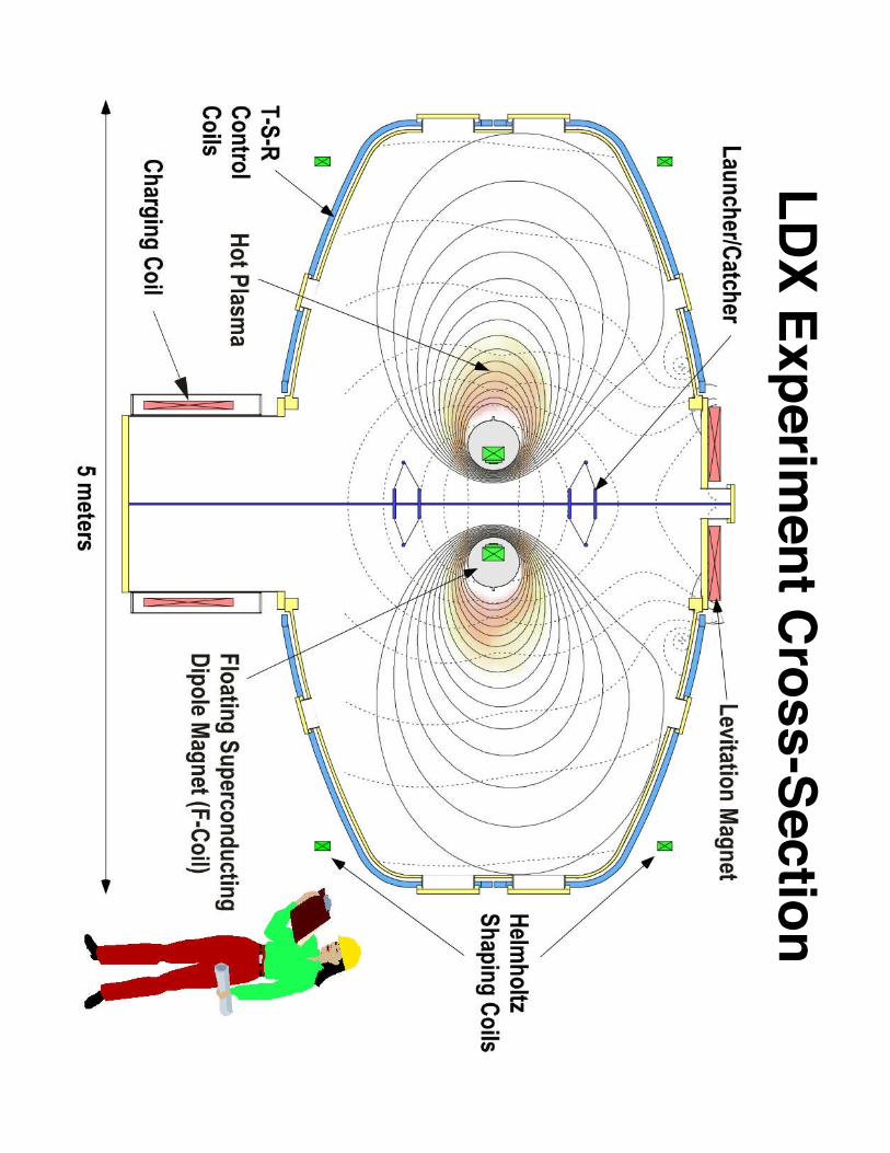
LDX Experiment Cross-Section

Wh
y dip
ole co
nfin
emen
t?•
Sim
plest
con
finem
ent field
•S
teady state
•H
igh
-b con
finem
ent
occu
rs natu
rally inm
agn
etosp
heres
(b ~ 3 in
Jup
iter)•
Po
ssibility o
f fusio
np
ow
er sou
rce with
near-classical
energ
y con
finem
ent
•O
pp
ortu
nity to
stud
yn
ew p
hysics
relevant to
fusio
nan
d sp
ace science
Th
e Io P
lasma
To
rus aro
un
d Ju
piter
J. Spencer
Dip
ole C
on
finem
ent an
d L
DX
:•C
on
cept is b
ased o
n o
bservatio
ns o
f the p
lasma p
rop
erties arou
nd
Jup
iter, created b
y a dip
ole co
nfin
emen
t
• b~ p
lasma p
ressure/ m
agn
etic pressu
re

Glo
w D
ischarg
e Pro
cess
An
od
e
An
od
e Sh
eath
Vacu
um
Vessel W
all(C
atho
de)
Large E (space charge
limited current flow
)
Electron density Æ
0
Quasi-neutral region;
Ions accelerate
Cath
od
e Sh
eath(m
inim
al ion
ization
)
Secondary
electrons
Fast electrons
Ions accelerate throughsheath
Neg
ativeG
low
(Plasm
a)
An
od
e Sh
eath
• Un
iform
ion
den
sity
• Co
llision
lessreg
ion
• No
ion
ization
• Accelerates
secon
dary electro
ns
back in
to g
low
Cath
od
e Sh
eath
• Min
imal io
nizatio
n
• Fast electro
ns take
collisio
nless p
athth
rou
gh
glo
w an
d h
itan
od
e
• Ion
s acceleratedÆ
kno
ck imp
urities o
ffvessel w
all

Po
tential D
rop
across G
low

Th
e GD
C P
rocess
•Gas and V
acuum pum
pingsystem
s:
•Vessel pum
ped down to
~10
-3 Torr
•Gas pum
ping systemintroduces H
or He gas
into vessel
•Glow
initiated Æim
purities liberated fromvessel w
alls
•Continual pum
pingrem
oves liberatedim
purities from vessel

Imp
ortan
ce of G
DC
for L
DX
•LD
X requires pure
hydrogenic plasma
Æexperim
ental objective isto exam
ine limits of
stability in high pressure(high b) plasm
as
•Large volum
e of plasma
and limited pow
eravailability
•Im
purities on the interior ofLD
X vessel w
all (such asoxygen, nitrogen, etc.)ejected into confinedplasm
a by plasma and
neutral bombardm
ent
•E
jected atoms radiate
power, causing the plasm
ato cool
•Im
purities can dissipatepow
er enough to severelylow
er confined plasma
pressure
•T
hus, LDX
vessel must be
free of impurities to obtain
experimental objective!

GD
C A
no
de P
rob
e•
GD
C anode probe enters and retracts from
main vessel via m
ounting system connected
to pre-existing flange on vessel
•P
robe attached to rigid, insulated stainlesssteel rod
•E
nd of rod outside vessel connects to fullnipple flange
•V
acuum-operated bellow
s encloses rodbetw
een exterior of vessel and full nippleflange
Filam
ent
entry
An
od
ep
rob
een
try
GD
C F
lang
e
* Draw
ing by Eugenio O
rtiz, Novem
ber 10, 2002
GD
C A
no
de P
rob
e
Em
issive Pro
be

GD
C A
no
de P
rob
e
An
od
e Su
pp
ort S
haft
•B
iggest concern in design:arcing!
•S
haft design takes into carefulaccount possibility of arcing
•1/8
” copper conductor shieldedw
ith 1/4” O
D alum
ina tube
•3/4
” OD
stainless steel main
support rod shielded with
1”OD
, 40” long alum
ina tube
•S
teel rod is welded to a blank
flange at lower end
•S
haft housed in bellowsÆ
mechanism
for insertion andretraction of G
DC
probe•V
iew of shaft upper end-- w
ill go inside probe
•Provides pow
er to anode via copper wire-
copper wire is attached to the inside of anode
•Stainless steel anode inserted into
vacuum vessel for G
DC

Insid
e An
od
e Pro
be
•K
ey to in
side o
f pro
be is b
oro
nn
itride cylin
der
•C
ylind
er pro
vides in
sulated
termin
ation
po
ints fo
r all shaft
com
po
nen
ts•
1/8” cop
per co
nd
ucto
r exits top
of
cylind
er and
is attached
to in
side o
fsteel p
rob
e•
BN
cylind
er is sup
po
rted in
side
sph
erical ano
de via steel d
iskw
elded
insid
e ano
de
Bo
ron
Nitrid
e Cylin
der
Cro
ss-section
of an
od
e pro
be
Stain
less Steel
Ho
llow
Sp
here
Set screw
Co
pp
er con
du
ctor
Half o
f steel ano
de

An
od
e Po
wer S
up
ply
•10.5
” H x 19
” W x 19” D
rack mount supply
•O
utput:–
800V D
C
–U
p to 7.5 A
•F
loating ground isolatespow
er supply from chassis
ground
•S
elected for high currentoutput, rem
ote operationcapability, and frontconsole design
•Manufactured by
Spellm
an HV
, Oct. 2002
12 kW P
ower S
upply

Po
wer T
ransfer C
on
nectio
n
Full
Nipple
Flange
Main S
teel Support R
odcom
ing down from
anode
1/4” alumina
Copper conductor
from anode
Copper from
feedthrough
Insulation fromfeedthrough
Copper connector
tube
Alum
inaencasing entire
connection
•1/8” copper conductor
attached internally toanode m
ust make solid
connection with pow
ersupply
•Very high risk of arcing
inside full nippleflange
Æ m
any regionsw
here ‘line of site’betw
een copper andother m
etals couldcause arcing and effectdischarge

Prein
oizatio
n F
ilamen
t
175 VA
VA
RIA
C
DC
Bias P
ower
Supply
Output:300V
, up to30m
A6V
, 24A
Filam
entT
ransformer
IsolationT
ransformer
To F
ilament
115V A
C in
115V A
C in
Lighted fuse holder with
2A fuse
Lighted fuse holder with
.1A fuse
On/O
fftogglesw
itch
GN
D
Po
wer tran
sfer system to
Filam
ent
Bias P
ower S
upply and Tungsten
Filam
ent
•Biased tungsten
filament inserted near
anode
•Aids in glow
dischargeby providing addedelectron source
•Also useful for
illuminating inside of
vacuum vessel

GD
C O
peratio
n P
lan
•P
reionization filament m
aynot be used in first G
DC
plasmas in order to test
only anode and high-voltage pow
er supply
•V
ery long period of glowdischarge w
ill run beforefirst LD
X plasm
as tothoroughly clean vessel
•G
DC
will use hydrogen
gas and then a shorterperiod of helium
gas
•C
urrently do not have Z-
detector to monitor w
hatis rem
oved from vessel
during GD
C
•D
o have 2-pi bolometer
(photodiode with green
filter)
•T
his will be used to
assess GD
C

GD
C O
peratio
n P
lan
•R
esidual Gas A
nalyzer(R
GA
) will m
onitor vacuumconditions betw
eenplasm
a shots
•O
ption to run GD
Cbetw
een shots will be
determined by vacuum
conditions as indicated byR
GA
•G
DC
will run for
approximately 7 hours total
in between run days
•G
DC
operates atpressure ~
10-3 T
orr
•F
uture Goal:
–W
ould like to automate
GD
C system
in the future-anode pow
er supply iscapable of rem
oteoperation
–T
his would also require
modifications to gas and
pressure systems

Co
nclu
sion
s
•G
DC
uses unconfined plasma to rem
oveim
purities from inside of LD
X vacuum
vessel•
Rem
oval of impurities essential for LD
Xexperim
ent•
GD
C design based on pre-existing flanges in
LDX
vessel•
Largest issue in design was to avoid arcing
•G
DC
first plasmas expected in D
ecember
2002!
Fo
r mo
re info
rmatio
n/u
pd
ates on
LD
X G
DC
,co
ntact S
arah D
agen
: dag
en@
psfc.m
it.edu

Referen
ces
1.H
.W K
ugel, W. B
lanchard, G. D
'Am
ico, R.
Gernhardt, and T
. Provost, "N
ST
XF
ilamen
t Preio
nizatio
n A
nd
Glo
wD
ischarg
e Clean
ing
System
s", PP
PL
Report (2000).
2.IT
ER
report, 1999