gigadevice semiconductor inc. gd32e230 arm cortex -m23 32 ... · gd32e230 firmware library user...
TRANSCRIPT
GD32E230 Firmware Library User Guide
1
GigaDevice Semiconductor Inc.
GD32E230
ARM® Cortex™-M23 32-bit MCU
Firmware Library
User Guide
Revison 1.0
(Aug. 2018)
GD32E230 Firmware Library User Guide
2
Table of Contents
Table of Contents ........................................................................................................... 2
List of Figures ................................................................................................................ 5
List of Tables .................................................................................................................. 6
1. Introduction ............................................................................................................ 19
1.1. Rules of User Manual and Firmware Library ........................................................... 19
1.1.1. Peripherals ....................................................................................................................... 19
1.1.2. Naming rules..................................................................................................................... 20
2. Firmware Library Overview ................................................................................... 21
2.1. File Structure of Firmware Library ........................................................................... 21
2.1.1. Examples Folder ............................................................................................................... 22
2.1.2. Firmware Folder ................................................................................................................ 22
2.1.3. Template Folder ................................................................................................................ 22
2.1.4. Utilities Folder ................................................................................................................... 25
2.2. File descriptions of Firmware Library ...................................................................... 26
3. Firmware Library of Standard Peripherals .......................................................... 27
3.1. Overview of Firmware Library of Standard Peripherals .......................................... 27
3.2. ADC ............................................................................................................................ 27
3.2.1. Descriptions of Peripheral registers ................................................................................... 27
3.2.2. Descriptions of Peripheral functions .................................................................................. 28
3.3. CMP ............................................................................................................................ 57
3.3.1. Descriptions of Peripheral registers ................................................................................... 57
3.3.2. Descriptions of Peripheral functions .................................................................................. 57
3.4. CRC ............................................................................................................................ 64
3.4.1. Descriptions of Peripheral registers ................................................................................... 65
3.4.2. Descriptions of Peripheral functions .................................................................................. 65
3.5. DBG ............................................................................................................................ 74
3.5.1. Descriptions of Peripheral registers ................................................................................... 74
3.5.2. Descriptions of Peripheral functions .................................................................................. 75
3.6. DMA ............................................................................................................................ 80
3.6.1. Descriptions of Peripheral registers ................................................................................... 80
3.6.2. Descriptions of Peripheral functions .................................................................................. 81
3.7. EXTI .......................................................................................................................... 103
3.7.1. Descriptions of Peripheral registers ................................................................................. 103
3.7.2. Descriptions of Peripheral functions ................................................................................ 103

GD32E230 Firmware Library User Guide
3
3.8. FMC ...........................................................................................................................112
3.8.1. Descriptions of Peripheral registers ................................................................................. 112
3.8.2. Descriptions of Peripheral functions ................................................................................ 113
3.9. FWDGT ..................................................................................................................... 134
3.9.1. Descriptions of Peripheral registers ................................................................................. 134
3.9.2. Descriptions of Peripheral functions ................................................................................ 135
3.10. GPIO ...................................................................................................................... 142
3.10.1. Descriptions of Peripheral registers ................................................................................. 142
3.10.2. Descriptions of Peripheral functions ................................................................................ 142
3.11. I2C ......................................................................................................................... 156
3.11.1. Descriptions of Peripheral registers ................................................................................. 156
3.11.2. Descriptions of Peripheral functions ................................................................................ 156
3.12. MISC ...................................................................................................................... 187
3.12.1. Descriptions of Peripheral registers ................................................................................. 188
3.12.2. Descriptions of Peripheral functions ................................................................................ 189
3.13. PMU ....................................................................................................................... 196
3.13.1. Descriptions of Peripheral registers ................................................................................. 196
3.13.2. Descriptions of Peripheral functions ................................................................................ 196
3.14. RCU ....................................................................................................................... 206
3.14.1. Descriptions of Peripheral registers ................................................................................. 206
3.14.2. Descriptions of Peripheral functions ................................................................................ 207
3.15. RTC ....................................................................................................................... 239
3.15.1. Descriptions of Peripheral registers ................................................................................. 239
3.15.2. Descriptions of Peripheral functions ................................................................................ 240
3.16. SPI ......................................................................................................................... 266
3.16.1. Descriptions of Peripheral registers ................................................................................. 266
3.16.2. Descriptions of Peripheral functions ................................................................................ 267
3.17. SYSCFG ................................................................................................................ 304
3.17.1. Descriptions of Peripheral registers ................................................................................. 304
3.17.2. Descriptions of Peripheral functions ................................................................................ 304
3.18. TIMER .................................................................................................................... 312
3.18.1. Descriptions of Peripheral registers ................................................................................. 312
3.18.2. Descriptions of Peripheral functions ................................................................................ 313
3.19. USART................................................................................................................... 387
3.19.1. Descriptions of Peripheral registers ................................................................................. 387
3.19.2. Descriptions of Peripheral functions ................................................................................ 388
3.20. WWDGT ................................................................................................................. 449
3.20.1. Descriptions of Peripheral registers ................................................................................. 449
3.20.2. Descriptions of Peripheral functions ................................................................................ 450

GD32E230 Firmware Library User Guide
4
4. Revision history ................................................................................................... 456

GD32E230 Firmware Library User Guide
5
List of Figures
Figure 2-1. File structure of firmware library of GD32E230 ...................................................................... 21
Figure 2-2. Select peripheral example files ................................................................................................. 23
Figure 2-3. Copy the peripheral example files ............................................................................................ 24
Figure 2-4. Open the project file .................................................................................................................... 24
Figure 2-5. Configure project files................................................................................................................. 25
Figure 2-6. Compile-debug-download .......................................................................................................... 25

GD32E230 Firmware Library User Guide
6
List of Tables
Table 1-1. Peripherals ...................................................................................................................................... 19
Table 2-1. Function descriptions of Firmware Library ............................................................................... 26
Table 3-1. Peripheral function format of Firmware Library ....................................................................... 27
Table 3-2. ADC Registers ................................................................................................................................ 28
Table 3-3. ADC firmware function .................................................................................................................. 28
Table 3-4. Function adc_deinit ....................................................................................................................... 30
Table 3-5. Function adc_enable ..................................................................................................................... 30
Table 3-6. Function adc_disable .................................................................................................................... 31
Table 3-7. Function adc_calibration_enable ................................................................................................ 31
Table 3-8. Function adc_dma_mode_enable ............................................................................................... 32
Table 3-9. Function adc_dma_mode_disable .............................................................................................. 32
Table 3-10. Function adc_tempsensor_vrefint_enable .............................................................................. 33
Table 3-11. Function adc_tempsensor_vrefint_disable ............................................................................. 34
Table 3-12. Function adc_discontinuous_mode_config ........................................................................... 34
Table 3-13. Function adc_special_function_config.................................................................................... 35
Table 3-14. Function adc_data_alignment_config ...................................................................................... 36
Table 3-15. Function adc_channel_length_config ...................................................................................... 37
Table 3-16. Function adc_regular_channel_config .................................................................................... 38
Table 3-17. Function adc_inserted_channel_config .................................................................................. 39
Table 3-18. Function adc_inserted_channel_offset_config ...................................................................... 40
Table 3-19. Function adc_external_trigger_config ..................................................................................... 41
Table 3-20. Function adc_external_trigger_source_config ...................................................................... 42
Table 3-21. Function adc_software_trigger_enable ................................................................................... 43
Table 3-22. Function adc_regular_data_read .............................................................................................. 44
Table 3-23. Function adc_inserted_data_read ............................................................................................ 45
Table 3-24. Function adc_flag_get ................................................................................................................ 45
Table 3-25. Function adc_flag_clear ............................................................................................................. 46
Table 3-26. Function adc_interrupt_flag_get ............................................................................................... 47
Table 3-27. Function adc_interrupt_flag_clear............................................................................................ 48
Table 3-28. Function adc_interrupt _enable ................................................................................................ 48
Table 3-29. Function adc_interrupt_disable ................................................................................................ 49
Table 3-30. Function adc_watchdog_single_channel_enable .................................................................. 50
Table 3-31. Function adc_watchdog_group_channel_enable .................................................................. 51
Table 3-32. Function adc_watchdog_disable .............................................................................................. 51
Table 3-33. Function adc_watchdog_threshold_config ............................................................................ 52
Table 3-34. Function adc_resolution_config ............................................................................................... 53
Table 3-35. Function adc_oversample_mode_config ................................................................................ 53
Table 3-36. Function adc_oversample_mode_enable................................................................................ 55
Table 3-37. Function adc_oversample_mode_disable .............................................................................. 56
Table 3-38. CMP Registers .............................................................................................................................. 57
GD32E230 Firmware Library User Guide
7
Table 3-39. CMP firmware function ............................................................................................................... 57
Table 3-40. Function cmp_deinit.................................................................................................................... 58
Table 3-41. Function cmp_mode_init ............................................................................................................ 58
Table 3-42. Function cmp_output_init .......................................................................................................... 60
Table 3-43. Function can_fd_init.................................................................................................................... 61
Table 3-44. Function cmp_disable................................................................................................................. 61
Table 3-45. Function cmp_switch_enable .................................................................................................... 62
Table 3-46. Function cmp_switch_disable ................................................................................................... 63
Table 3-47. Function cmp_output_level_get................................................................................................ 63
Table 3-48. Function cmp_lock_enable ........................................................................................................ 64
Table 3-49. CRC Registers .............................................................................................................................. 65
Table 3-50. CRC firmware function................................................................................................................ 65
Table 3-51. Function crc_deinit ...................................................................................................................... 66
Table 3-52. Function crc_reverse_output_data_enable ............................................................................ 66
Table 3-53. Function crc_reverse_output_data_disable ........................................................................... 67
Table 3-54. Function crc_data_register_reset ............................................................................................. 67
Table 3-55. Function crc_data_register_read .............................................................................................. 68
Table 3-56. Function crc_free_data_register_read ..................................................................................... 69
Table 3-57. Function crc_free_data_register_write .................................................................................... 69
Table 3-58. Function crc_init_data_register_write ..................................................................................... 70
Table 3-59. Function crc_input_data_reverse_config................................................................................ 71
Table 3-60. Function crc_polynomial_size_set ........................................................................................... 71
Table 3-61. Function crc_polynomial_set .................................................................................................... 72
Table 3-62. Function crc_single_data_calculate......................................................................................... 73
Table 3-63. Function crc_block_data_calculate .......................................................................................... 73
Table 3-64. DBG Registers .............................................................................................................................. 74
Table 3-65. DBG firmware function ............................................................................................................... 75
Table 3-66. Enum dbg_periph_enum ............................................................................................................ 75
Table 3-67. Function dbg_deinit .................................................................................................................... 76
Table 3-68. Function dbg_id_get ................................................................................................................... 76
Table 3-69. Function dbg_low_power_enable ............................................................................................. 77
Table 3-70. Function dbg_low_power_disable ............................................................................................ 78
Table 3-71. Function dbg_periph_enable ..................................................................................................... 78
Table 3-72. Function dbg_periph_disable .................................................................................................... 79
Table 3-73. DMA Registers .............................................................................................................................. 80
Table 3-74. DMA firmware function ............................................................................................................... 81
Table 3-75. Structure dma_parameter_struct .............................................................................................. 82
Table 3-76. Function dma_deinit.................................................................................................................... 82
Table 3-77. Function dma_para_init .............................................................................................................. 83
Table 3-78. Function dma_init ........................................................................................................................ 84
Table 3-79. Function dma_circulation_enable ............................................................................................ 85
Table 3-80. Function dma_circulation_disable ........................................................................................... 85
Table 3-81. Function dma_memory_to_memory_enable .......................................................................... 86
Table 3-82. Function dma_memory_to_memory_disable ......................................................................... 87
GD32E230 Firmware Library User Guide
8
Table 3-83. Function dma_channel_enable ................................................................................................. 87
Table 3-84. Function dma_channel_disable ................................................................................................ 88
Table 3-85. Function dma_periph_address_config .................................................................................... 88
Table 3-86. Function dma_memory_address_config ................................................................................. 89
Table 3-87. Function dma_transfer_number_config .................................................................................. 90
Table 3-88. Function dma_transfer_number_get ........................................................................................ 91
Table 3-89. Function dma_priority_config ................................................................................................... 91
Table 3-90. Function dma_memory_width_config ..................................................................................... 92
Table 3-91. Function dma_periph_width_config ......................................................................................... 93
Table 3-92. Function dma_memory_increase_enable ............................................................................... 94
Table 3-93. Function dma_memory_increase_disable .............................................................................. 95
Table 3-94. Function dma_periph_increase_enable .................................................................................. 95
Table 3-95. Function dma_periph_increase_disable ................................................................................. 96
Table 3-96. Function dma_transfer_direction_config ................................................................................ 97
Table 3-97. Function dma_flag_get ............................................................................................................... 98
Table 3-98. Function dma_flag_clear ............................................................................................................ 99
Table 3-99. Function dma_interrupt_flag_get ............................................................................................. 99
Table 3-100. Function dma_interrupt_flag_clear .......................................................................................100
Table 3-101. Function dma_interrupt_enable .............................................................................................101
Table 3-102. Function dma_interrupt_disable ............................................................................................102
Table 3-103. EXTI Registers ...........................................................................................................................103
Table 3-104. EXTI firmware function ............................................................................................................103
Table 3-105. Function exti_deinit ..................................................................................................................104
Table 3-106. Function exti_init ......................................................................................................................105
Table 3-107. Function exti_interrupt_enable ..............................................................................................106
Table 3-108. Function exti_event_enable ....................................................................................................106
Table 3-109. Function exti_interrupt_disable .............................................................................................107
Table 3-110. Function exti_event_disable ...................................................................................................107
Table 3-111. Function exti_flag_get ..............................................................................................................108
Table 3-112. Function exti_flag_clear ..........................................................................................................109
Table 3-113. Function exti_interrupt_flag_get ............................................................................................109
Table 3-114. Function exti_interrupt_flag_clear .........................................................................................110
Table 3-115. Function exti_software_interrupt_enable .............................................................................111
Table 3-116. Function exti_software_interrupt_disable ............................................................................111
Table 3-117. FMC Registers ...........................................................................................................................112
Table 3-118. FMC firmware function .............................................................................................................113
Table 3-119. fmc_state_enum ........................................................................................................................114
Table 3-120. Function fmc_unlock................................................................................................................114
Table 3-121. Function fmc_lock ....................................................................................................................115
Table 3-122. Function fmc_wscnt_set .........................................................................................................115
Table 3-123. Function fmc_prefetch_enable ...............................................................................................116
Table 3-124. Function fmc_prefetch_disable ..............................................................................................117
Table 3-125. Function fmc_page_erase .......................................................................................................117
Table 3-126. Function fmc_mass_erase ......................................................................................................118

GD32E230 Firmware Library User Guide
9
Table 3-127. Function fmc_doubleword_program .....................................................................................119
Table 3-128. Function fmc_word_program .................................................................................................119
Table 3-129. Function ob_unlock ..................................................................................................................120
Table 3-130. Function ob_lock ......................................................................................................................121
Table 3-131. Function ob_reset .....................................................................................................................121
Table 3-132. Function option_byte_value_get............................................................................................122
Table 3-133. Function ob_erase ....................................................................................................................122
Table 3-134. Function ob_write_protection_enable ..................................................................................123
Table 3-135. Function ob_security_protection_config .............................................................................124
Table 3-136. Function ob_user_write ...........................................................................................................125
Table 3-137. Function ob_data_program .....................................................................................................125
Table 3-138. Function ob_user_get ..............................................................................................................126
Table 3-139. Function ob_data_get ..............................................................................................................127
Table 3-140. Function ob_write_protection_get .........................................................................................127
Table 3-141. Function ob_obstat_plevel_get ..............................................................................................128
Table 3-142. Function fmc_interrupt_enable ..............................................................................................128
Table 3-143. Function fmc_interrupt_disable .............................................................................................129
Table 3-144. Function fmc_flag_get .............................................................................................................130
Table 3-145. Function fmc_flag_clear ..........................................................................................................131
Table 3-146. Function fmc_interrupt_flag_get ...........................................................................................131
Table 3-147. Function fmc_interrupt_flag_clear ........................................................................................132
Table 3-148. Function fmc_state_get ...........................................................................................................133
Table 3-149. Function fmc_ready_wait ........................................................................................................134
Table 3-149. FWDGT Registers .....................................................................................................................135
Table 3-150. FWDGT firmware function .......................................................................................................135
Table 3-151. Function fwdgt_write_ensable ...............................................................................................135
Table 3-152. Function fwdgt_write_disable ................................................................................................136
Table 3-153. Function fwdgt_enable ............................................................................................................137
Table 3-154. Function fwdgt_prescaler_value_config ..............................................................................137
Table 3-155. Function fwdgt_reload_value_config ....................................................................................138
Table 3-156. Function fwdgt_window_value_config .................................................................................138
Table 3-157. Function fwdgt_counter_reload .............................................................................................139
Table 3-158. Function fwdgt_config .............................................................................................................140
Table 3-159. Function fwdgt_flag_get ..........................................................................................................141
Table 3-161. GPIO Registers ..........................................................................................................................142
Table 3-161. GPIO firmware function ...........................................................................................................142
Table 3-163. Function gpio_deinit ................................................................................................................143
Table 3-163. Function gpio_mode_set .........................................................................................................144
Table 3-164. Function gpio_output_options_set .......................................................................................145
Table 3-165. Function gpio_bit_set ..............................................................................................................146
Table 3-166. Function gpio_bit_reset...........................................................................................................147
Table 3-167. Function gpio_bit_write ...........................................................................................................148
Table 3-168. Function gpio_port_write ........................................................................................................149
Table 3-169. Function gpio_input_bit_get...................................................................................................149
GD32E230 Firmware Library User Guide
10
Table 3-170. Function gpio_input_port_get ................................................................................................150
Table 3-171. Function gpio_output_bit_get ................................................................................................151
Table 3-172. Function gpio_output_port_get .............................................................................................152
Table 3-173. Function gpio_af_set ...............................................................................................................152
Table 3-174. Function gpio_pin_lock ...........................................................................................................154
Table 3-176. Function gpio_bit_toggle ........................................................................................................154
Table 3-176. Function gpio_port_toggle .....................................................................................................155
Table 3-177. I2C Registers .............................................................................................................................156
Table 3-178. I2C firmware function ...............................................................................................................157
Table 3-179. Function i2c_deinit ...................................................................................................................158
Table 3-180. Function i2c_clock_config ......................................................................................................159
Table 3-181. Function i2c_mode_addr_config ...........................................................................................159
Table 3-182. Function i2c_smbus_type_config .........................................................................................161
Table 3-183. Function i2c_ack_config .........................................................................................................161
Table 3-184. Function i2c_ackpos_config...................................................................................................162
Table 3-185. Function i2c_master_addressing ..........................................................................................163
Table 3-186. Function i2c_dualaddr_enable ...............................................................................................164
Table 3-187. Function i2c_dualaddr_enable ...............................................................................................165
Table 3-188. Function i2c_enable .................................................................................................................165
Table 3-189. Function i2c_disable ................................................................................................................166
Table 3-190. Function i2c_start_on_bus .....................................................................................................167
Table 3-191. Function i2c_stop_on_bus .....................................................................................................167
Table 3-192. Function i2c_data_transmit ....................................................................................................168
Table 3-193. Function i2c_data_receive ......................................................................................................169
Table 3-194. Function i2c_dma_enable .......................................................................................................169
Table 3-195. Function i2c_dma_last_transfer_config ...............................................................................170
Table 3-196. Function i2c_stretch_scl_low_config ...................................................................................171
Table 3-197. Function i2c_slave_response_to_gcall_config ...................................................................172
Table 3-198. Function i2c_software_reset_config .....................................................................................172
Table 3-199. Function i2c_pec_enable ........................................................................................................173
Table 3-200. Function i2c_pec_transfer_enable ........................................................................................174
Table 3-201. Function i2c_pec_value_get ...................................................................................................175
Table 3-202. Function i2c_smbus_issue_alert ...........................................................................................175
Table 3-203. Function i2c_smbus_arp_enable ...........................................................................................176
Table 3-204. Function i2c_sam_enable .......................................................................................................177
Table 3-205. Function i2c_sam_disable ......................................................................................................178
Table 3-206. Function i2c_sam_timeout_enable........................................................................................178
Table 3-207. Function i2c_sam_timeout_disable.......................................................................................179
Table 3-208. Function i2c_flag_get...............................................................................................................180
Table 3-209. Function i2c_flag_clear ...........................................................................................................181
Table 3-210. Function i2c_interrupt_enable ...............................................................................................183
Table 3-211. Function i2c_interrupt_disable...............................................................................................184
Table 3-212. Function i2c_interrupt_flag_get .............................................................................................185
Table 3-213. Function i2c_interrupt_flag_clear ..........................................................................................186

GD32E230 Firmware Library User Guide
11
Table 3-214. NVIC Registers ..........................................................................................................................188
Table 3-215. SysTick Registers .....................................................................................................................188
Table 3-216. IRQn_Type ..................................................................................................................................189
Table 3-217. MISC firmware function ...........................................................................................................190
Table 3-218. Function nvic_irq_enable ........................................................................................................191
Table 3-219. Function nvic_irq_disable .......................................................................................................191
Table 3-220. Function nvic_system_reset...................................................................................................192
Table 3-221. Function nvic_vector_table_set .............................................................................................193
Table 3-222. Function system_lowpower_set ............................................................................................193
Table 3-223. Function system_lowpower_reset .........................................................................................194
Table 3-224. Function systick_clksource_set ............................................................................................195
Table 3-225. PMU Registers ...........................................................................................................................196
Table 3-226. PMU firmware function ............................................................................................................196
Table 3-227. Function pmu_deinit ................................................................................................................197
Table 3-228. Function pmu_lvd_select ........................................................................................................197
Table 3-229. Function pmu_ldo_output_select ..........................................................................................198
Table 3-230. Function pmu_lvd_disable ......................................................................................................199
Table 3-231. Function pmu_to_sleepmode .................................................................................................199
Table 3-232. Function pmu_to_deepsleepmode ........................................................................................200
Table 3-233. Function pmu_to_standbymode ............................................................................................201
Table 3-234. Function pmu_wakeup_pin_enable.......................................................................................202
Table 3-235. Function pmu_wakeup_pin_disable .....................................................................................202
Table 3-236. Function pmu_backup_write_enable ....................................................................................203
Table 3-237. Function pmu_backup_write_disable ...................................................................................204
Table 3-238. Function pmu_flag_clear .........................................................................................................204
Table 3-239. Function pmu_flag_get ............................................................................................................205
Table 3-240. RCU Registers ...........................................................................................................................206
Table 3-241. RCU firmware function ............................................................................................................207
Table 3-242. Function rcu_deinit ..................................................................................................................208
Table 3-243. Function rcu_periph_clock_enable .......................................................................................209
Table 3-244. Function rcu_periph_clock_disable ......................................................................................210
Table 3-245. Function rcu_periph_clock_sleep_enable ...........................................................................211
Table 3-246. Function rcu_periph_clock_sleep_disable ..........................................................................212
Table 3-247. Function rcu_periph_reset_enable........................................................................................212
Table 3-248. Function rcu_periph_reset_disable.......................................................................................213
Table 3-249. Function rcu_bkp_reset_enable ............................................................................................214
Table 3-250. Function rcu_bkp_reset_disable ...........................................................................................215
Table 3-251. Function rcu_system_clock_source_config........................................................................215
Table 3-252. Function rcu_system_clock_source_get .............................................................................216
Table 3-253. Function rcu_ahb_clock_config ............................................................................................217
Table 3-254. Function rcu_apb1_clock_config ..........................................................................................218
Table 3-255. Function rcu_apb2_clock_config ..........................................................................................218
Table 3-256. Function rcu_adc_clock_config .............................................................................................219
Table 3-257. Function rcu_ckout_config .....................................................................................................220
GD32E230 Firmware Library User Guide
12
Table 3-258. Function rcu_pll_config...........................................................................................................221
Table 3-259. Function rcu_usart_clock_config ..........................................................................................222
Table 3-260. Function rcu_rtc_clock_config ..............................................................................................223
Table 3-261. Function rcu_hxtal_prediv_config .........................................................................................223
Table 3-262. Function rcu_lxtal_drive_capability_config .........................................................................224
Table 3-263. Function rcu_flag_get ..............................................................................................................225
Table 3-264. Function rcu_all_reset_flag_clear .........................................................................................226
Table 3-265. Function rcu_interrupt_flag_get ............................................................................................227
Table 3-266. Function rcu_interrupt_flag_clear .........................................................................................228
Table 3-267. Function rcu_interrupt_enable ...............................................................................................229
Table 3-268. Function rcu_interrupt_disable ..............................................................................................230
Table 3-269. Function rcu_osci_stab_wait .................................................................................................230
Table 3-270. Function rcu_osci_on ..............................................................................................................231
Table 3-271. Function rcu_osci_off ..............................................................................................................232
Table 3-272. Function rcu_osci_bypass_mode_enable ...........................................................................233
Table 3-273. Function rcu_osci_bypass_mode_disable ..........................................................................234
Table 3-274. Function rcu_hxtal_clock_monitor_enable .........................................................................234
Table 3-275. Function rcu_hxtal_clock_monitor_disable ........................................................................235
Table 3-276. Function rcu_irc8m_adjust_value_set ..................................................................................236
Table 3-277. Function rcu_irc28m_adjust_value_set................................................................................236
Table 3-278. Function rcu_voltage_key_unlock ........................................................................................237
Table 3-279. Function rcu_deepsleep_voltage_set ...................................................................................237
Table 3-280. Function rcu_clock_freq_get ..................................................................................................238
Table 3-281. RTC Registers ...........................................................................................................................239
Table 3-282.RTC firmware function ..............................................................................................................240
Table 3-283. rtc_parameter_struct................................................................................................................242
Table 3-284. rtc_alarm_struct ........................................................................................................................242
Table 3-285. rtc_timestamp_struct ...............................................................................................................242
Table 3-286. rtc_tamper_struct .....................................................................................................................243
Table 3-287. Function rtc_deinit ...................................................................................................................243
Table 3-288. Function rtc_init ........................................................................................................................244
Table 3-289. Function rtc_init_mode_enter ................................................................................................245
Table 3-290. Function rtc_init_mode_exit ...................................................................................................245
Table 3-291. Function rtc_register_sync_wait ...........................................................................................246
Table 3-292. Function rtc_current_time_get ...............................................................................................247
Table 3-293. Function rtc_subsecond_get ..................................................................................................247
Table 3-294. Function rtc_alarm_config ......................................................................................................248
Table 3-295. Function rtc_alarm_subsecond_config ................................................................................249
Table 3-296. Function rtc_alarm_enable .....................................................................................................250
Table 3-297. Function rtc_alarm_disable ....................................................................................................251
Table 3-298. Function rtc_alarm_get............................................................................................................251
Table 3-299. Function rtc_alarm_subsecond_get .....................................................................................252
Table 3-300. Function rtc_timestamp_enable ............................................................................................253
Table 3-301. Function rtc_timestamp_disable ...........................................................................................253

GD32E230 Firmware Library User Guide
13
Table 3-302. Function rtc_timestamp_get ...................................................................................................254
Table 3-303. Function rtc_timestamp_subsecond_get .............................................................................255
Table 3-304. Function rtc_timestamp_enable ............................................................................................255
Table 3-305. Function rtc_tamper_disable ..................................................................................................256
Table 3-306. Function rtc_interrupt_enable ................................................................................................257
Table 3-307. Function rtc_interrupt_disable ...............................................................................................257
Table 3-308. Function rtc_flag_get ...............................................................................................................258
Table 3-309. Function rtc_flag_clear ............................................................................................................259
Table 3-310. Function rtc_alter_output_config ..........................................................................................260
Table 3-311. rtc_calibration_config ..............................................................................................................261
Table 3-312. rtc_hour_adjust .........................................................................................................................262
Table 3-313. rtc_second_adjust ....................................................................................................................263
Table 3-314. rtc_bypass_shadow_enable ...................................................................................................264
Table 3-315. rtc_bypass_shadow_disable ..................................................................................................264
Table 3-316. rtc_refclock_detection_enable ...............................................................................................265
Table 3-317. rtc_refclock_detection_disable ..............................................................................................265
Table 3-318. SPI/I2S registers........................................................................................................................266
Table 3-319. SPI/I2S firmware function ........................................................................................................267
Table 3-320. spi_parameter_struct ...............................................................................................................269
Table 3-321. Function spi_i2s_deinit ...........................................................................................................269
Table 3-322. Function spi_i2s_deinit ...........................................................................................................270
Table 3-323. Function spi_init .......................................................................................................................271
Table 3-324. Function spi_enable .................................................................................................................272
Table 3-325. Function spi_disable ................................................................................................................272
Table 3-326. Function i2s_init .......................................................................................................................273
Table 3-327. Function i2s_psc_config .........................................................................................................274
Table 3-328. Function i2s_enable .................................................................................................................276
Table 3-329. Function i2s_disable ................................................................................................................277
Table 3-330. Function spi_nss_output_enable ..........................................................................................277
Table 3-331. Function spi_nss_output_disable .........................................................................................278
Table 3-332. Function spi_nss_internal_high ............................................................................................279
Table 3-333. Function spi_nss_internal_low ..............................................................................................279
Table 3-334. Function spi_dma_enable .......................................................................................................280
Table 3-335. Function spi_dma_disable ......................................................................................................281
Table 3-336. Function spi_i2s_data_frame_format_config ......................................................................282
Table 3-337. Function spi_i2s_data_transmit .............................................................................................282
Table 3-338. Function spi_i2s_data_receive...............................................................................................283
Table 3-339. Function spi_bidirectional_transfer_config .........................................................................284
Table 3-340. Function spi_crc_polynomial_set .........................................................................................285
Table 3-341. Function spi_crc_polynomial_get .........................................................................................285
Table 3-342. Function spi_crc_on ................................................................................................................286
Table 3-343. Function spi_crc_off ................................................................................................................287
Table 3-344. Function spi_crc_next .............................................................................................................287
Table 3-345. Function spi_crc_get ...............................................................................................................288
GD32E230 Firmware Library User Guide
14
Table 3-346. Function spi_ti_mode_enable ................................................................................................289
Table 3-347. Function spi_ti_mode_disable ...............................................................................................289
Table 3-348. Function spi_nssp_mode_enable ..........................................................................................290
Table 3-349. Function spi_nssp_mode_disable .........................................................................................291
Table 3-350. Function qspi_enable...............................................................................................................291
Table 3-351. Function qspi_disable .............................................................................................................292
Table 3-352. Function qspi_write_enable....................................................................................................293
Table 3-353. Function qspi_read_enable ....................................................................................................293
Table 3-354. Function qspi_io23_output_enable .......................................................................................294
Table 3-355. Function qspi_io23_output_disable ......................................................................................295
Table 3-356. Function spi_i2s_interrupt_enable ........................................................................................295
Table 3-357. Function spi_i2s_interrupt_disable .......................................................................................296
Table 3-358. Function spi_i2s_interrupt_flag_get .....................................................................................297
Table 3-359. Function spi_i2s_flag_get .......................................................................................................298
Table 3-360. Function spi_crc_error_clear .................................................................................................300
Table 3-361. Function spi_fifo_access_size_config .................................................................................300
Table 3-362. Function spi_transmit_odd_config .......................................................................................301
Table 3-363. Function spi_receive_odd_config .........................................................................................302
Table 3-364. Function spi_crc_length_set ..................................................................................................303
Table 3-365. SYSCFG Registers....................................................................................................................304
Table 3-366. SYSCFG firmware function .....................................................................................................304
Table 3-367. Function syscfg_deinit ............................................................................................................305
Table 3-368. Function syscfg_dma_remap_enable ...................................................................................305
Table 3-369. Function syscfg_dma_remap_disable ..................................................................................306
Table 3-370. Function syscfg_ high_current_enable ................................................................................307
Table 3-371. Function syscfg_high_current_disable ................................................................................308
Table 3-372. Function syscfg_exti_line_config ..........................................................................................308
Table 3-373. Function syscfg_lock_config .................................................................................................309
Table 3-374. Function irq_latency_set .........................................................................................................310
Table 3-375. Function syscfg_flag_get ........................................................................................................311
Table 3-376. Function syscfg_flag_ clear ....................................................................................................311
Table 3-377. TIMERx Registers .....................................................................................................................312
Table 3-378.TIMERx firmware function ........................................................................................................313
Table 3-379. Structure timer_parameter_struct .........................................................................................317
Table 3-380. Structure timer_break_parameter_struct .............................................................................317
Table 3-381. Structure timer_oc_parameter_struct ...................................................................................317
Table 3-382. Structure timer_ic_parameter_struct ....................................................................................318
Table 3-383. Function timer_deinit ...............................................................................................................318
Table 3-384. Function timer_struct_para_init .............................................................................................319
Table 3-385. Function timer_init ...................................................................................................................320
Table 3-386. Function timer_enable .............................................................................................................321
Table 3-387. Function timer_disable ............................................................................................................321
Table 3-388. Function timer_auto_reload_shadow_enable .....................................................................322
Table 3-389. Function timer_auto_reload_shadow_disable ....................................................................323

GD32E230 Firmware Library User Guide
15
Table 3-390. Function timer_update_event_enable...................................................................................323
Table 3-391. Function timer_update_event_disable .................................................................................324
Table 3-392. Function timer_counter_alignment .......................................................................................325
Table 3-393. Function timer_counter_up_direction ..................................................................................326
Table 3-394. timer_counter_down_direction ..............................................................................................326
Table 3-395. Function timer_prescaler_config ...........................................................................................327
Table 3-396. Function timer_repetition_value_config...............................................................................328
Table 3-397. Function timer_autoreload_value_config ............................................................................329
Table 3-398. Function timer_counter_value_config ..................................................................................329
Table 3-399. Function timer_counter_read .................................................................................................330
Table 3-400. Function timer_prescaler_read ..............................................................................................331
Table 3-401. Function timer_single_pulse_mode_config ........................................................................332
Table 3-402. Function timer_update_source_config .................................................................................332
Table 3-403. Function t timer_ocpre_clear_source_config .....................................................................333
Table 3-404. Function timer_interrupt_enable ...........................................................................................334
Table 3-405. Function timer_interrupt_disable ..........................................................................................335
Table 3-406. Function timer_interrupt_flag_get .........................................................................................336
Table 3-407. Function timer_interrupt_flag_clear ......................................................................................337
Table 3-408. Function timer_flag_get...........................................................................................................338
Table 3-409. Function timer_flag_clear .......................................................................................................340
Table 3-410. Function timer_dma_enable ...................................................................................................341
Table 3-411. Function timer_dma_disable ..................................................................................................342
Table 3-412. Function timer_channel_dma_request_source_select ......................................................343
Table 3-413. Function timer_dma_transfer_config....................................................................................344
Table 3-414. Function timer_event_software_generate............................................................................346
Table 3-415. Function timer_break_struct_para_init ................................................................................347
Table 3-416. Function timer_break_config .................................................................................................347
Table 3-417. Function timer_break_enable .................................................................................................348
Table 3-418. Function timer_break_disable ................................................................................................349
Table 3-419. Function timer_automatic_output_enable ...........................................................................350
Table 3-420. Function timer_automatic_output_disable ..........................................................................350
Table 3-421. Function timer_primary_output_config ................................................................................351
Table 3-422. Function timer_channel_control_shadow_config ..............................................................352
Table 3-423. Function timer_channel_control_shadow_update_config................................................353
Table 3-424. Function timer_channel_output_struct_para_init ..............................................................354
Table 3-425. Function timer_channel_output_config ...............................................................................354
Table 3-426. Function timer_channel_output_mode_config ...................................................................356
Table 3-427. Function timer_channel_output_pulse_value_config........................................................357
Table 3-428. Function timer_channel_output_shadow_config ...............................................................358
Table 3-429. Function timer_channel_output_fast_config.......................................................................359
Table 3-430. Function timer_channel_output_clear_config ....................................................................360
Table 3-431. Function timer_channel_output_polarity_config ................................................................361
Table 3-432. Function timer_channel_complementary_output_polarity_config .................................362
Table 3-433. Function timer_channel_output_state_config ....................................................................363

GD32E230 Firmware Library User Guide
16
Table 3-434. Function timer_channel_complementary_output_state_config ......................................364
Table 3-435. Function timer_channel_input_struct_para_init .................................................................365
Table 3-436. Function timer_input_capture_config...................................................................................366
Table 3-437. Function timer_channel_input_capture_prescaler_config ...............................................367
Table 3-438. Function timer_channel_capture_value_register_read .....................................................368
Table 3-439. Function timer_input_pwm_capture_config ........................................................................369
Table 3-440. Function timer_hall_mode_config .........................................................................................370
Table 3-441. Function timer_input_trigger_source_select ......................................................................371
Table 3-442. Function timer_master_output_trigger_source_select .....................................................372
Table 3-443. Function timer_slave_mode_select.......................................................................................374
Table 3-444. Function timer_master_slave_mode_config .......................................................................375
Table 3-445. Function timer_external_trigger_config ...............................................................................376
Table 3-446. Function timer_quadrature_decoder_mode_config ...........................................................377
Table 3-447. Function timer_internal_clock_config ..................................................................................378
Table 3-448. Function timer_internal_trigger_as_external_clock_config .............................................379
Table 3-449. Function timer_external_trigger_as_external_clock_config ............................................380
Table 3-450. Function timer_external_clock_mode0_config ...................................................................381
Table 3-451. Function timer_external_clock_mode1_config ...................................................................382
Table 3-452. Function timer_external_clock_mode1_disable .................................................................384
Table 3-453. Function timer_channel_remap_config ................................................................................384
Table 3-454. Function timer_write_chxval_register_config .....................................................................385
Table 3-455. Function timer_output_value_selection_config..................................................................386
Table 3-456. USART Registers ......................................................................................................................387
Table 3-457. USART firmware function........................................................................................................388
Table 3-458. Function usart_deinit ...............................................................................................................391
Table 3-459. Function usart_baudrate_set .................................................................................................392
Table 3-460. Function usart_parity_config .................................................................................................392
Table 3-461. Function usart_word_length_set ...........................................................................................393
Table 3-462. Function usart_stop_bit_set ...................................................................................................394
Table 3-463. Function usart_enable .............................................................................................................395
Table 3-464. Function usart_disable ............................................................................................................395
Table 3-465. Function usart_transmit_config .............................................................................................396
Table 3-466. Function usart_receive_config...............................................................................................397
Table 3-467. Function usart_ data_first_config ..........................................................................................398
Table 3-468. Function usart_invert_config .................................................................................................398
Table 3-469. Function usart_overrun_enable .............................................................................................400
Table 3-470. Function usart_overrun_disable ............................................................................................400
Table 3-471. Function usart_oversample_config.......................................................................................401
Table 3-472. Function usart_sample_bit_config ........................................................................................402
Table 3-473. Function usart_receiver_timeout_enable .............................................................................402
Table 3-474. Function usart_receiver_timeout_disable ............................................................................403
Table 3-475. Function usart_receiver_timeout_threshold_config ..........................................................404
Table 3-476. Function usart_data_transmit ................................................................................................405
Table 3-477. Function usart_data_receive ..................................................................................................405
GD32E230 Firmware Library User Guide
17
Table 3-478. Function usart_autobaud_detection_enable .......................................................................406
Table 3-479. Function usart_autobaud_detection_disable ......................................................................407
Table 3-480. Function usart_autobaud_detection_mode_config ...........................................................407
Table 3-481. Function usart_address_config .............................................................................................408
Table 3-482. Function usart_address_detection_mode_config ..............................................................409
Table 3-483. Function usart_mute_mode_enable ......................................................................................410
Table 3-484. Function usart_mute_mode_disable .....................................................................................410
Table 3-485. Function usart_mute_mode_wakeup_config ......................................................................411
Table 3-486. Function usart_lin_mode_enable ..........................................................................................412
Table 3-487. Function usart_lin_mode_disable .........................................................................................412
Table 3-488. Function usart_lin_break_dection_length_config ..............................................................413
Table 3-489. Function usart_halfduplex_enable ........................................................................................414
Table 3-490. Function usart_halfduplex_disable .......................................................................................414
Table 3-491. Function usart_clock_enable .................................................................................................415
Table 3-492. Function usart_clock_disable ................................................................................................416
Table 3-493. Function usart_synchronous_clock_ config .......................................................................416
Table 3-494. Function usart_guard_time_config .......................................................................................418
Table 3-495. Function usart_smartcard_mode_enable ............................................................................418
Table 3-496. Function usart_smartcard_mode_disable ...........................................................................419
Table 3-497. Function usart_smartcard_mode_nack_enable ..................................................................420
Table 3-498. Function usart_smartcard_mode_nack_disable .................................................................420
Table 3-499. Function usart_smartcard_mode_early_nack_enable .......................................................421
Table 3-500. Function usart_smartcard_mode_early_nack_disable ......................................................422
Table 3-501. Function usart_smartcard_autoretry_config .......................................................................422
Table 3-502. Function usart_block_length_config ....................................................................................423
Table 3-503. Function usart_irda_mode_enable ........................................................................................424
Table 3-504. Function usart_irda_mode_disable .......................................................................................424
Table 3-505. Function usart_prescaler_config ...........................................................................................425
Table 3-506. Function usart_irda_lowpower_config .................................................................................426
Table 3-507. Function usart_hardware_flow_rts_config ..........................................................................427
Table 3-508. Function usart_hardware_flow_cts_config..........................................................................427
Table 3-509. Function usart_hardware_flow_coherence_config ............................................................428
Table 3-510. Function usart_rs485_driver_enable ....................................................................................429
Table 3-511. Function usart_rs485_driver_disable....................................................................................430
Table 3-512. Function usart_driver_assertime_config .............................................................................430
Table 3-513. Function usart_driver_deassertime_config .........................................................................431
Table 3-514. Function usart_depolarity_config .........................................................................................432
Table 3-515. Function usart_dma_receive_config .....................................................................................433
Table 3-516. Function usart_dma_transmit_config ...................................................................................434
Table 3-517. Function usart_reception_error_dma_disable ....................................................................434
Table 3-518. Function usart_reception_error_dma_enable .....................................................................435
Table 3-519. Function usart_wakeup_enable .............................................................................................436
Table 3-520. Function usart_wakeup_disable ............................................................................................436
Table 3-521. Function usart_wakeup_mode_config .................................................................................437

GD32E230 Firmware Library User Guide
18
Table 3-522. Function usart_receive_fifo_enable ......................................................................................438
Table 3-523. Function usart_receive_fifo_disable .....................................................................................439
Table 3-524. Function usart_receive_fifo_counter_number ....................................................................439
Table 3-525. Function usart_flag_get...........................................................................................................440
Table 3-526. Function usart_flag_clear .......................................................................................................442
Table 3-527. Function usart_interrupt_enable ...........................................................................................443
Table 3-528. Function usart_interrupt_disable ..........................................................................................444
Table 3-529. Function usart_command_enable .........................................................................................445
Table 3-530. Function usart_interrupt_flag_get .........................................................................................446
Table 3-531. Function usart_interrupt_flag_clear ......................................................................................448
Table 3-532. WWDGT Registers ....................................................................................................................450
Table 3-533. WWDGT firmware function .....................................................................................................450
Table 3-534. Function wwdgt_deinit ............................................................................................................450
Table 3-535. Function wwdgt_enable...........................................................................................................451
Table 3-536. Function wwdgt_counter_update ..........................................................................................451
Table 3-537. Function wwdgt_config ...........................................................................................................452
Table 3-538. Function wwdgt_interrupt_enable .........................................................................................453
Table 3-539. Function wwdgt_flag_get ........................................................................................................454
Table 3-540. Function wwdgt_flag_clear .....................................................................................................455
Table 4-1. Revision history ............................................................................................................................456

GD32E230 Firmware Library User Guide
19
1. Introduction
This manual introduces firmware library of GD32E230 devices which are 32-bit
microcontrollers based on the ARM processor.
The firmware library is a firmware function package, including program, data structure and
macro definitions, all the performance features of peripherals of GD32E230 devices are
involved in the package. The peripheral driving code and firmware examples on evaluation
board are also included in firmware library. Users need not learn each peripherals in details
and it’s easy to apply a peripheral by using the firmware library. Using firmware library can
greatly reduce programming time, thereby reducing development costs.
The driving code of each peripheral is concluded by a group of functions, which describes all
the performance features of the peripheral. Users can drive a peripheral by a group of APIs
(application programming interface), all the APIs are standardized about the code structure,
function name and parameter names.
All the driving source code accord with MISRA-C:2004 standard (example files accord with
extended ANSI-C standard), and will not be influenced by differences of IDEs, except the
startup files which are written differently according to the IDEs.
The commonly used firmware library includes all the functions of all the peripherals, so the
code size and the execution speed may not be the optimal. For most applications, users can
use the library functions directly, while for the applications which are strict with the code size
and execution speed, the firmware library can be used as the reference resource of how to
configure a peripheral, and users adjust the code according to actual needs.
The overall structure of the firmware library user manual is shown as below:
Rules of user manual and firmware library;
Firmware library overview;
Functions and registers descriptions of firmware library.
1.1. Rules of User Manual and Firmware Library
1.1.1. Peripherals
Table 1-1. Peripherals
Peripherals Descriptions
ADC Analog-to-digital converter
CMP Comparator
CRC CRC calculation unit
DBG Debug
DMA Direct memory access controller
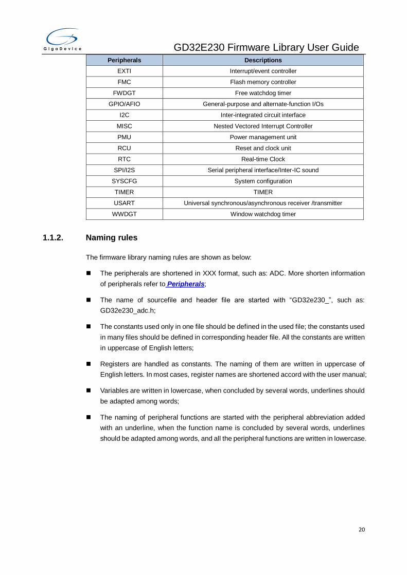
GD32E230 Firmware Library User Guide
20
Peripherals Descriptions
EXTI Interrupt/event controller
FMC Flash memory controller
FWDGT Free watchdog timer
GPIO/AFIO General-purpose and alternate-function I/Os
I2C Inter-integrated circuit interface
MISC Nested Vectored Interrupt Controller
PMU Power management unit
RCU Reset and clock unit
RTC Real-time Clock
SPI/I2S Serial peripheral interface/Inter-IC sound
SYSCFG System configuration
TIMER TIMER
USART Universal synchronous/asynchronous receiver /transmitter
WWDGT Window watchdog timer
1.1.2. Naming rules
The firmware library naming rules are shown as below:
The peripherals are shortened in XXX format, such as: ADC. More shorten information
of peripherals refer to Peripherals;
The name of sourcefile and header file are started with “GD32e230_”, such as:
GD32e230_adc.h;
The constants used only in one file should be defined in the used file; the constants used
in many files should be defined in corresponding header file. All the constants are written
in uppercase of English letters;
Registers are handled as constants. The naming of them are written in uppercase of
English letters. In most cases, register names are shortened accord with the user manual;
Variables are written in lowercase, when concluded by several words, underlines should
be adapted among words;
The naming of peripheral functions are started with the peripheral abbreviation added
with an underline, when the function name is concluded by several words, underlines
should be adapted among words, and all the peripheral functions are written in lowercase.
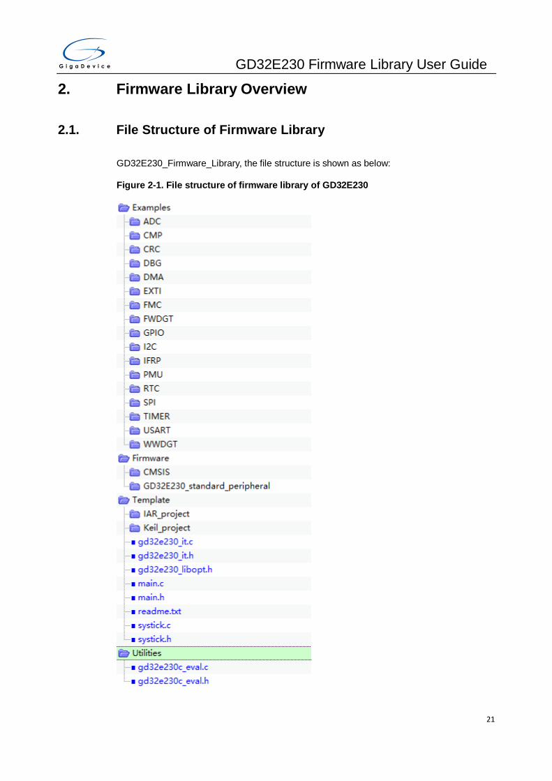
GD32E230 Firmware Library User Guide
21
2. Firmware Library Overview
2.1. File Structure of Firmware Library
GD32E230_Firmware_Library, the file structure is shown as below:
Figure 2-1. File structure of firmware library of GD32E230
GD32E230 Firmware Library User Guide
22
2.1.1. Examples Folder
Examples folder, each of GD32 peripheral has a subfolder. Each subfolder contains one or
more examples of the peripheral, to show how to use the peripheral correctly. Each of the
example subfolder includes the files shown as below:
readme.txt: the description and using guide of the example;
GD32e230_libopt.h: the header file configures all the peripherals used in the example,
included by different “DEFINE” sentences (all the peripherals are enabled by default);
GD32e230_it.c: the source file include all the interrupt service routines (if no interrupt is
used, then all the function bodies are empty);
GD32e230.it.h: the header file include all the prototypes of the interrupt service routines;
systick.c: the source file include the precise time delay functions by using systick;
systick.h: the header file include the prototype of the precise time delay functions by
using systick;
main.c: example code. Note: all the examples are not influenced by software IDEs.
2.1.2. Firmware Folder
Firmware folder includes all the subfolder and files which are the core part of the firmware:
CMSIS subfolder includes the Cortex M23 kernel support files, the startup file based on
the Cortex M23 kernel processor, the global header file of GD32E230 and system
configuration file;
GD32E230_standard_peripheral subfolder:
– Include subfolder includes all the header files of firmware libray, users need not modify
this folder;
– Source subfolder includes all the source files of firmware library, users need not modify
this folder;
Note:All the codes accord with MISRA-C:2004 standard, and will not be influenced by
different software IDEs.
2.1.3. Template Folder
Template folder includes a simple demo of how to use LED, how to print by USART and use
key to control, (IAR_project is run in IAR, and Keil_project is run in Keil5). User can use the
project template to compile the formware examples, the steps are shown as below:
Select files
Open “Examples” folder, select the module to be tested, such as SPI, open ”SPI” folder, select
an example of SPI, such as ”SPI_master_transmit_slave_receive_interrupt”, shown as below:

GD32E230 Firmware Library User Guide
23
Figure 2-2. Select peripheral example files
Copy files
Open “Template” folder, keep the folders of ” IAR_project” and ” Keil_project”, and delete the
other files, then copy all the files in “SPI_master_transmit_slave_receive_interrupt” folder to
the “Template” subfolder, shown as below:

GD32E230 Firmware Library User Guide
24
Figure 2-3. Copy the peripheral example files
Open a project
GD provides project in Keil and IAR, users can open project in different IDEs according to
their need, such as ”Keil_project”, open \Template\Keil_project\Project.uvproj, shown as
below:
Figure 2-4. Open the project file

GD32E230 Firmware Library User Guide
25
Because different module and different functions adopt different files, users should add or
delete the files in project according to the copied files, shown as below:
Figure 2-5. Configure project files
Compile-Debug-Download
First compile the project, if there is no error, then select the right jumper cap according to the
description of readme, download the project to the target board, and there will be the
phenomenon showed accord with the description of readme. The usage of IDE can refer to
corresponding software user guide. If users are using Keil, the figure is shown as below:
Figure 2-6. Compile-debug-download
2.1.4. Utilities Folder
Utilities folder includes files about the firmware examples on evaluation board:
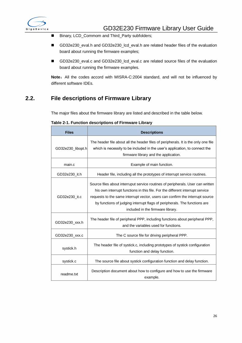
GD32E230 Firmware Library User Guide
26
Binary, LCD_Commom and Third_Party subfolders;
GD32e230_eval.h and GD32e230_lcd_eval.h are related header files of the evaluation
board about running the firmware examples;
GD32e230_eval.c and GD32e230_lcd_eval.c are related source files of the evaluation
board about running the firmware examples.
Note:All the codes accord with MISRA-C:2004 standard, and will not be influenced by
different software IDEs.
2.2. File descriptions of Firmware Library
The major files about the firmware library are listed and described in the table below.
Table 2-1. Function descriptions of Firmware Library
Files Descriptions
GD32e230_libopt.h
The header file about all the header files of peripherals. It is the only one file
which is necessity to be included in the user’s application, to connect the
firmware library and the application.
main.c Example of main function.
GD32e230_it.h Header file, including all the prototypes of interrupt service routines.
GD32e230_it.c
Source files about interruput service routines of peripherals. User can written
his own interrupt functions in this file. For the different interrupt service
requests to the same interrupt vector, users can confirm the interrupt source
by functions of judging interrupt flags of peripherals. The functions are
included in the firmware library.
GD32e230_xxx.h The header file of peripheral PPP, including functions about peripheral PPP,
and the variables used for functions.
GD32e230_xxx.c The C source file for driving peripheral PPP.
systick.h The header file of systick.c, including prototypes of systick configuration
function and delay function.
systick.c The source file about systick configuration function and delay function.
readme.txt Description document about how to configure and how to use the firmware
example.
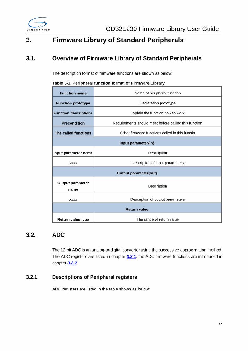
GD32E230 Firmware Library User Guide
27
3. Firmware Library of Standard Peripherals
3.1. Overview of Firmware Library of Standard Peripherals
The description format of firmware functions are shown as below:
Table 3-1. Peripheral function format of Firmware Library
Function name Name of peripheral function
Function prototype Declaration prototype
Function descriptions Explain the function how to work
Precondition Requirements should meet before calling this function
The called functions Other firmware functions called in this functin
Input parameter{in}
Input parameter name Description
xxxx Description of input parameters
Output parameter{out}
Output parameter
name Description
xxxx Description of output parameters
Return value
Return value type The range of return value
3.2. ADC
The 12-bit ADC is an analog-to-digital converter using the successive approximation method.
The ADC registers are listed in chapter 3.2.1, the ADC firmware functions are introduced in
chapter 3.2.2.
3.2.1. Descriptions of Peripheral registers
ADC registers are listed in the table shown as below:
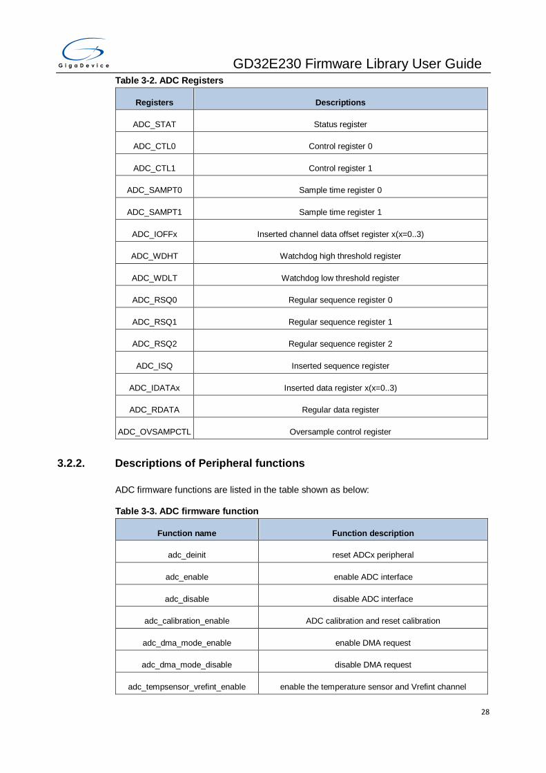
GD32E230 Firmware Library User Guide
28
Table 3-2. ADC Registers
Registers Descriptions
ADC_STAT Status register
ADC_CTL0 Control register 0
ADC_CTL1 Control register 1
ADC_SAMPT0 Sample time register 0
ADC_SAMPT1 Sample time register 1
ADC_IOFFx Inserted channel data offset register x(x=0..3)
ADC_WDHT Watchdog high threshold register
ADC_WDLT Watchdog low threshold register
ADC_RSQ0 Regular sequence register 0
ADC_RSQ1 Regular sequence register 1
ADC_RSQ2 Regular sequence register 2
ADC_ISQ Inserted sequence register
ADC_IDATAx Inserted data register x(x=0..3)
ADC_RDATA Regular data register
ADC_OVSAMPCTL Oversample control register
3.2.2. Descriptions of Peripheral functions
ADC firmware functions are listed in the table shown as below:
Table 3-3. ADC firmware function
Function name Function description
adc_deinit reset ADCx peripheral
adc_enable enable ADC interface
adc_disable disable ADC interface
adc_calibration_enable ADC calibration and reset calibration
adc_dma_mode_enable enable DMA request
adc_dma_mode_disable disable DMA request
adc_tempsensor_vrefint_enable enable the temperature sensor and Vrefint channel

GD32E230 Firmware Library User Guide
29
Function name Function description
adc_tempsensor_vrefint_disable disable the temperature sensor and Vrefint channel
adc_resolution_config configure ADC resolution
adc_discontinuous_mode_config configure ADC discontinuous mode
adc_special_function_config enable or disable ADC special function
adc_data_alignment_config configure ADC data alignment
adc_channel_length_config configure the length of regular channel group or inserted
channel group
adc_regular_channel_config configure ADC regular channel
adc_inserted_channel_config configure ADC inserted channel
adc_inserted_channel_offset_config configure ADC inserted channel offset
adc_external_trigger_config enable ADC external trigger
adc_external_trigger_source_config configure ADC external trigger source
adc_software_trigger_enable enable ADC software trigger
adc_regular_data_read read ADC regular group data register
adc_inserted_data_read read ADC inserted group data register
adc_flag_get get the ADC flag bits
adc_flag_clear clear the ADC flag bits
adc_interrupt_flag_get get the ADC interrupt bits
adc_interrupt_flag_clear clear the ADC flag
adc_interrupt_enable enable ADC interrupt
adc_interrupt_disable disable ADC interrupt
adc_watchdog_single_channel_enabl
e configure ADC analog watchdog single channel
adc_watchdog_group_channel_enabl
e configure ADC analog watchdog group channel
adc_watchdog_disable disable ADC analog watchdog
adc_watchdog_threshold_config configure ADC analog watchdog threshold
adc_resolution_config

GD32E230 Firmware Library User Guide
30
Function name Function description
adc_oversample_mode_config configure ADC oversample mode
adc_oversample_mode_enable enable ADC oversample mode
adc_oversample_mode_disable disable ADC oversample mode
adc_deinit
The description of adc_deinit is shown as below:
Table 3-4. Function adc_deinit
Function name adc_deinit
Function prototype void adc_deinit(void);
Function descriptions reset ADC peripheral
Precondition -
The called functions rcu_periph_reset_enable / rcu_periph_reset_disable
Output parameter{out}
- -
Return value
- -
Example:
/* reset ADC */
adc_deinit();
adc_enable
The description of adc_enable is shown as below:
Table 3-5. Function adc_enable
Function name adc_enable
Function prototype void adc_enable(void);
Function descriptions enable ADC interface
Precondition -
The called functions -
Output parameter{out}

GD32E230 Firmware Library User Guide
31
- -
Return value
- -
Example:
/* enable ADC */
adc_enable();
adc_disable
The description of adc_disable is shown as below:
Table 3-6. Function adc_disable
Function name adc_disable
Function prototype void adc_disable(void);
Function descriptions disable ADC interface
Precondition -
The called functions -
Output parameter{out}
- -
Return value
- -
Example:
/* disable ADC */
adc_disable();
adc_calibration_enable
The description of adc_calibration_enable is shown as below:
Table 3-7. Function adc_calibration_enable
Function name adc_calibration_enable
Function prototype void adc_calibration_enable(void);
Function descriptions ADC calibration and reset calibration
Precondition -

GD32E230 Firmware Library User Guide
32
The called functions -
Output parameter{out}
- -
Return value
- -
Example:
/* ADC calibration and reset calibration */
adc_calibration_enable();
adc_dma_mode_enable
The description of adc_dma_mode_enable is shown as below:
Table 3-8. Function adc_dma_mode_enable
Function name adc_dma_mode_enable
Function prototype void adc_dma_mode_enable(void);
Function descriptions enable ADC DMA request
Precondition -
The called functions -
Output parameter{out}
- -
Return value
- -
Example:
/* enable ADC DMA request */
adc_dma_mode_enable();
adc_dma_mode_disable
The description of adc_dma_mode_disable is shown as below:
Table 3-9. Function adc_dma_mode_disable
Function name adc_dma_mode_disable
Function prototype void adc_dma_mode_disable(void);

GD32E230 Firmware Library User Guide
33
Function descriptions disable ADC DMA request
Precondition -
The called functions -
Output parameter{out}
- -
Return value
- -
Example:
/* disable ADC DMA request */
adc_dma_mode_disable();
adc_tempsensor_vrefint_enable
The description of adc_tempsensor_vrefint_enable is shown as below:
Table 3-10. Function adc_tempsensor_vrefint_enable
Function name adc_tempsensor_vrefint_enable
Function prototype void adc_tempsensor_vrefint_enable(void);
Function descriptions enable the temperature sensor and Vrefint channel
Precondition -
The called functions -
Input parameter{in}
- -
Output parameter{out}
- -
Return value
- -
Example:
/* enable the temperature sensor and Vrefint channel */
adc_tempsensor_vrefint_enable();

GD32E230 Firmware Library User Guide
34
adc_tempsensor_vrefint_disable
The description of adc_tempsensor_vrefint_disable is shown as below:
Table 3-11. Function adc_tempsensor_vrefint_disable
Function name adc_tempsensor_vrefint_disable
Function prototype void adc_tempsensor_vrefint_disable(void);
Function descriptions disable the temperature sensor and Vrefint channel
Precondition -
The called functions -
Input parameter{in}
- -
Output parameter{out}
- -
Return value
- -
Example:
/* disable the temperature sensor and Vrefint channel */
adc_tempsensor_vrefint_disable();
adc_discontinuous_mode_config
The description of adc_discontinuous_mode_config is shown as below:
Table 3-12. Function adc_discontinuous_mode_config
Function name adc_discontinuous_mode_config
Function prototype void adc_discontinuous_mode_config(uint8_t channel_group, uint8_t
length);
Function descriptions configure ADC discontinuous mode
Precondition -
The called functions -
Input parameter{in}
adc_channel_group select the channel group
ADC_REGULAR_CHA regular channel group

GD32E230 Firmware Library User Guide
35
NNEL
ADC_INSERTED_CHA
NNEL inserted channel group
ADC_CHANNEL_DISC
ON_DISABLE disable discontinuous mode of regular and inserted channel
Input parameter{in}
length number of conversions in discontinuous mode, the number can be 1..8 for
regular channel, the number has no effect for inserted channel
Output parameter{out}
- -
Return value
- -
Example:
/* configure ADC regular channel group discontinuous mode */
adc_discontinuous_mode_config(ADC_REGULAR_CHANNEL, 6);
adc_special_function_config
The description of adc_special_function_config is shown as below:
Table 3-13. Function adc_special_function_config
Function name adc_special_function_config
Function prototype void adc_special_function_config(uint32_t function, ControlStatus
newvalue);
Function descriptions enable or disable ADC special function
Precondition -
The called functions -
Input parameter{in}
function the function to config
ADC_SCAN_MODE scan mode select
ADC_INSERTED_CHA
NNEL_AUTO inserted channel group convert automatically
ADC_CONTINUOUS_ continuous mode select

GD32E230 Firmware Library User Guide
36
MODE
Input parameter{in}
newvalue control value
ENABLE enable function
DISABLE disable function
Output parameter{out}
- -
Return value
- -
Example:
/* enable ADC scan mode */
adc_special_function_config(ADC_SCAN_MODE, ENABLE);
adc_data_alignment_config
The description of adc_data_alignment_config is shown as below:
Table 3-14. Function adc_data_alignment_config
Function name adc_data_alignment_config
Function prototype void adc_data_alignment_config(uint32_t data_alignment);
Function descriptions configure ADCx data alignment
Precondition -
The called functions -
Input parameter{in}
data_alignment data alignment select
ADC_DATAALIGN_RIG
HT LSB alignment
ADC_DATAALIGN_LE
FT MSB alignment
Output parameter{out}
- -
Return value

GD32E230 Firmware Library User Guide
37
- -
Example:
/* configure ADC data alignment */
adc_data_alignment_config(ADC_DATAALIGN_RIGHT);
adc_channel_length_config
The description of adc_channel_length_config is shown as below:
Table 3-15. Function adc_channel_length_config
Function name adc_channel_length_config
Function prototype void adc_channel_length_config(uint8_t channel_group, uint32_t length);
Function descriptions configure the length of regular channel group or inserted channel group
Precondition -
The called functions -
Input parameter{in}
channel_group select the channel group
ADC_REGULAR_CHA
NNEL regular channel group
ADC_INSERTED_CHA
NNEL inserted channel group
Input parameter{in}
length the length of the channel, regular channel 1-16, inserted channel 1-4
Output parameter{out}
- -
Return value
- -
Example:
/* configure the length of ADC regular channel */
adc_channel_length_config(ADC_REGULAR_CHANNEL, 4);
adc_regular_channel_config
The description of adc_regular_channel_config is shown as below:

GD32E230 Firmware Library User Guide
38
Table 3-16. Function adc_regular_channel_config
Function name adc_regular_channel_config
Function prototype void adc_regular_channel_config(uint8_t rank, uint8_t channel, uint32_t
sample_time);
Function descriptions configure ADC regular channel
Precondition -
The called functions -
Input parameter{in}
rank the regular group sequence rank, this parameter must be between 0 to 15
Input parameter{in}
channel the selected ADC channel
ADC_CHANNEL_x ADC Channelx (x=0..9,16,17)
Input parameter{in}
sample_time the sample time value
ADC_SAMPLETIME_1
POINT5 1.5 cycles
ADC_SAMPLETIME_7
POINT5 7.5 cycles
ADC_SAMPLETIME_1
3POINT5 13.5 cycles
ADC_SAMPLETIME_2
8POINT5 28.5 cycles
ADC_SAMPLETIME_4
1POINT5 41.5 cycles
ADC_SAMPLETIME_5
5POINT5 55.5 cycles
ADC_SAMPLETIME_7
1POINT5 71.5 cycles
ADC_SAMPLETIME_2
39POINT5 239.5 cycles
Output parameter{out}
- -

GD32E230 Firmware Library User Guide
39
Return value
- -
Example:
/* configure ADC regular channel */
adc_regular_channel_config(1, ADC_CHANNEL_0, ADC_SAMPLETIME_7POINT5);
adc_inserted_channel_config
The description of adc_inserted_channel_config is shown as below:
Table 3-17. Function adc_inserted_channel_config
Function name adc_inserted_channel_config
Function prototype void adc_inserted_channel_config(uint8_t rank, uint8_t channel, uint32_t
sample_time);
Function descriptions configure ADC inserted channel
Precondition -
The called functions -
Input parameter{in}
rank the inserted group sequencer rank, this parameter must be between 0 to 3
Input parameter{in}
channel the selected ADC channel
ADC_CHANNEL_x ADC Channelx (x=0..9,16,17)
Input parameter{in}
sample_time the sample time value
ADC_SAMPLETIME_1
POINT5 1.5 cycles
ADC_SAMPLETIME_7
POINT5 7.5 cycles
ADC_SAMPLETIME_1
3POINT5 13.5 cycles
ADC_SAMPLETIME_2
8POINT5 28.5 cycles
ADC_SAMPLETIME_4 41.5 cycles
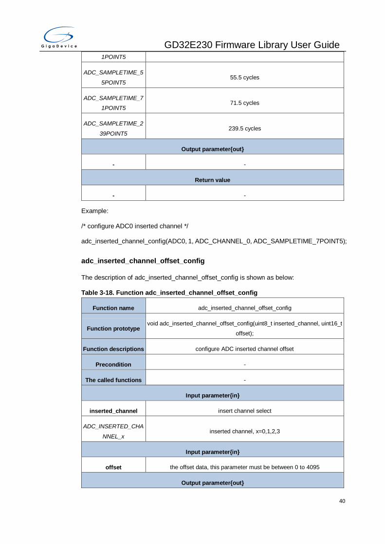
GD32E230 Firmware Library User Guide
40
1POINT5
ADC_SAMPLETIME_5
5POINT5 55.5 cycles
ADC_SAMPLETIME_7
1POINT5 71.5 cycles
ADC_SAMPLETIME_2
39POINT5 239.5 cycles
Output parameter{out}
- -
Return value
- -
Example:
/* configure ADC0 inserted channel */
adc_inserted_channel_config(ADC0, 1, ADC_CHANNEL_0, ADC_SAMPLETIME_7POINT5);
adc_inserted_channel_offset_config
The description of adc_inserted_channel_offset_config is shown as below:
Table 3-18. Function adc_inserted_channel_offset_config
Function name adc_inserted_channel_offset_config
Function prototype void adc_inserted_channel_offset_config(uint8_t inserted_channel, uint16_t
offset);
Function descriptions configure ADC inserted channel offset
Precondition -
The called functions -
Input parameter{in}
inserted_channel insert channel select
ADC_INSERTED_CHA
NNEL_x inserted channel, x=0,1,2,3
Input parameter{in}
offset the offset data, this parameter must be between 0 to 4095
Output parameter{out}
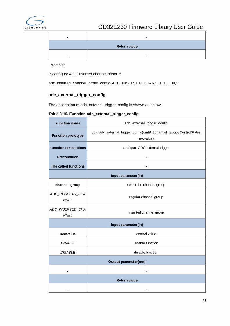
GD32E230 Firmware Library User Guide
41
- -
Return value
- -
Example:
/* configure ADC inserted channel offset */
adc_inserted_channel_offset_config(ADC_INSERTED_CHANNEL_0, 100);
adc_external_trigger_config
The description of adc_external_trigger_config is shown as below:
Table 3-19. Function adc_external_trigger_config
Function name adc_external_trigger_config
Function prototype void adc_external_trigger_config(uint8_t channel_group, ControlStatus
newvalue);
Function descriptions configure ADC external trigger
Precondition -
The called functions -
Input parameter{in}
channel_group select the channel group
ADC_REGULAR_CHA
NNEL regular channel group
ADC_INSERTED_CHA
NNEL inserted channel group
Input parameter{in}
newvalue control value
ENABLE enable function
DISABLE disable function
Output parameter{out}
- -
Return value
- -
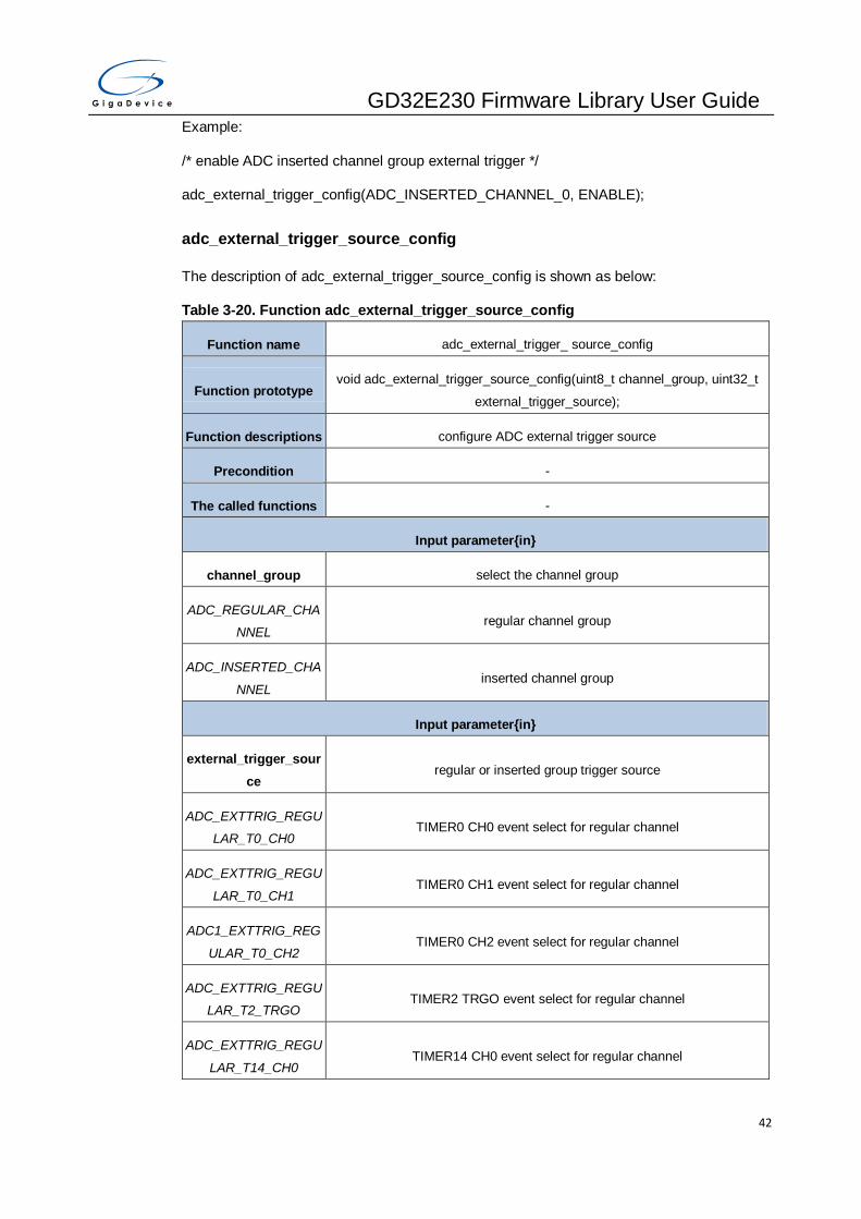
GD32E230 Firmware Library User Guide
42
Example:
/* enable ADC inserted channel group external trigger */
adc_external_trigger_config(ADC_INSERTED_CHANNEL_0, ENABLE);
adc_external_trigger_source_config
The description of adc_external_trigger_source_config is shown as below:
Table 3-20. Function adc_external_trigger_source_config
Function name adc_external_trigger_ source_config
Function prototype void adc_external_trigger_source_config(uint8_t channel_group, uint32_t
external_trigger_source);
Function descriptions configure ADC external trigger source
Precondition -
The called functions -
Input parameter{in}
channel_group select the channel group
ADC_REGULAR_CHA
NNEL regular channel group
ADC_INSERTED_CHA
NNEL inserted channel group
Input parameter{in}
external_trigger_sour
ce regular or inserted group trigger source
ADC_EXTTRIG_REGU
LAR_T0_CH0 TIMER0 CH0 event select for regular channel
ADC_EXTTRIG_REGU
LAR_T0_CH1 TIMER0 CH1 event select for regular channel
ADC1_EXTTRIG_REG
ULAR_T0_CH2 TIMER0 CH2 event select for regular channel
ADC_EXTTRIG_REGU
LAR_T2_TRGO TIMER2 TRGO event select for regular channel
ADC_EXTTRIG_REGU
LAR_T14_CH0 TIMER14 CH0 event select for regular channel

GD32E230 Firmware Library User Guide
43
ADC_EXTTRIG_REGU
LAR_EXTI_11 external interrupt line 11 for regular channel
ADC_EXTTRIG_REGU
LAR_NONE software trigger for regular channel
ADC_EXTTRIG_INSER
TED_T0_TRGO TIMER0 TRGO event select for inserted channel
ADC_EXTTRIG_INSER
TED_T0_CH3 TIMER0 CH3 event select for inserted channel
ADC_EXTTRIG_INSER
TED_T2_CH3 TIMER2 CH3 event select for inserted channel
ADC_EXTTRIG_INSER
TED_T14_TRGO TIMER14 TRGO event select for inserted channel
ADC_EXTTRIG_INSER
TED_EXTI_15 external interrupt line 15 for inserted channel
ADC_EXTTRIG_INSER
TED_NONE software trigger for inserted channel
Output parameter{out}
- -
Return value
- -
Example:
/* configure ADC regular channel external trigger source */
adc_external_trigger_source_config(ADC_REGULAR_CHANNEL,
ADC_EXTTRIG_REGULAR_T0_CH0);
adc_software_trigger_enable
The description of adc_software_trigger_enable is shown as below:
Table 3-21. Function adc_software_trigger_enable
Function name adc_software_trigger_enable
Function prototype void adc_software_trigger_enable(uint8_t channel_group);
Function descriptions enable ADC software trigger
Precondition -
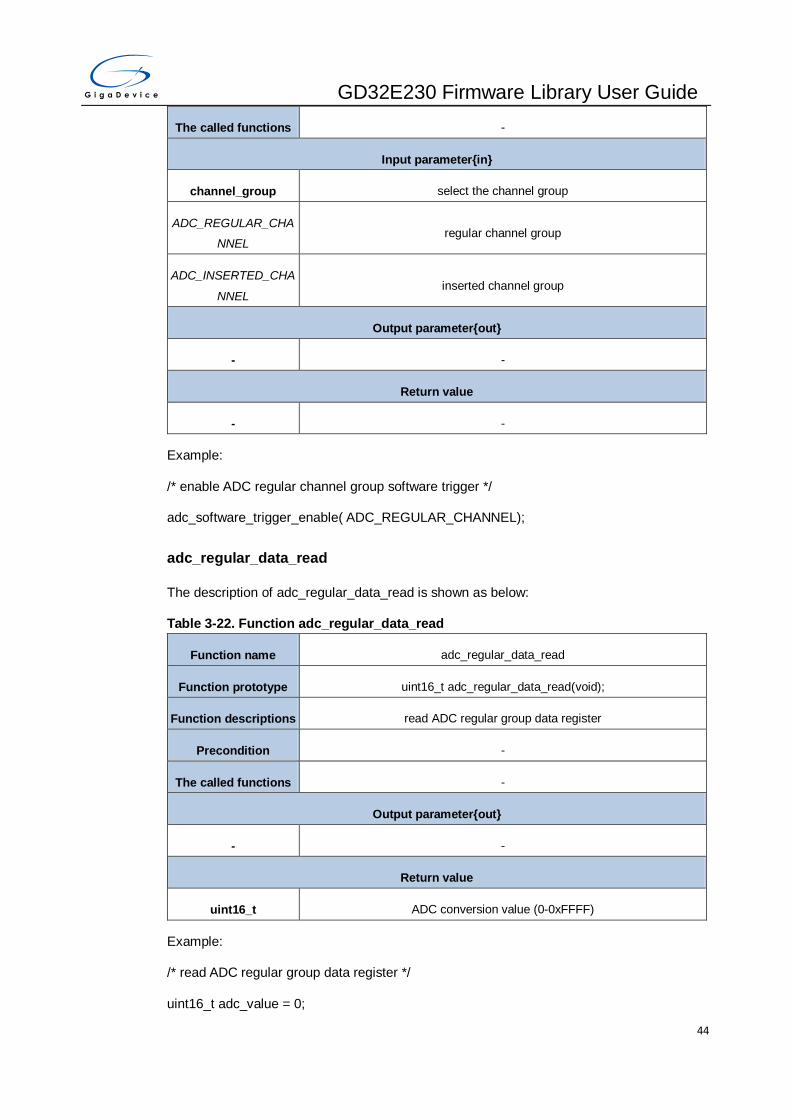
GD32E230 Firmware Library User Guide
44
The called functions -
Input parameter{in}
channel_group select the channel group
ADC_REGULAR_CHA
NNEL regular channel group
ADC_INSERTED_CHA
NNEL inserted channel group
Output parameter{out}
- -
Return value
- -
Example:
/* enable ADC regular channel group software trigger */
adc_software_trigger_enable( ADC_REGULAR_CHANNEL);
adc_regular_data_read
The description of adc_regular_data_read is shown as below:
Table 3-22. Function adc_regular_data_read
Function name adc_regular_data_read
Function prototype uint16_t adc_regular_data_read(void);
Function descriptions read ADC regular group data register
Precondition -
The called functions -
Output parameter{out}
- -
Return value
uint16_t ADC conversion value (0-0xFFFF)
Example:
/* read ADC regular group data register */
uint16_t adc_value = 0;

GD32E230 Firmware Library User Guide
45
adc_value = adc_regular_data_read();
adc_inserted_data_read
The description of adc_inserted_data_read is shown as below:
Table 3-23. Function adc_inserted_data_read
Function name adc_inserted_data_read
Function prototype uint16_t adc_inserted_data_read(uint8_t inserted_channel);
Function descriptions read ADC inserted group data register
Precondition -
The called functions -
Input parameter{in}
inserted_channel insert channel select
ADC_INSERTED_CHA
NNEL_x inserted Channelx, x=0,1,2,3
Output parameter{out}
- -
Return value
uint16_t ADC conversion value (0-0xFFFF)
Example:
/* read ADC inserted group data register */
uint16_t adc_value = 0;
adc_value = adc_inserted_data_read (ADC_INSERTED_CHANNEL_0);
adc_flag_get
The description of adc_flag_get is shown as below:
Table 3-24. Function adc_flag_get
Function name adc_flag_get
Function prototype FlagStatus adc_flag_get(uint32_t flag);
Function descriptions get the ADC flag bits
Precondition -

GD32E230 Firmware Library User Guide
46
The called functions -
Input parameter{in}
flag the adc flag bits
ADC_FLAG_WDE analog watchdog event flag
ADC_FLAG_EOC end of group conversion flag
ADC_FLAG_EOIC end of inserted group conversion flag
ADC_FLAG_STIC start flag of inserted channel group
ADC_FLAG_STRC start flag of regular channel group
Output parameter{out}
- -
Return value
FlagStatus SET or RESET
Example:
/* get the ADC analog watchdog flag bits*/
FlagStatus flag_value;
flag_value = adc_flag_get(ADC_FLAG_WDE);
adc_flag_clear
The description of adc_flag_clear is shown as below:
Table 3-25. Function adc_flag_clear
Function name adc_flag_clear
Function prototype void adc_flag_clear(uint32_t flag);
Function descriptions clear the ADC flag bits
Precondition -
The called functions -
Input parameter{in}
flag the adc flag bits
ADC_FLAG_WDE analog watchdog event flag
ADC_FLAG_EOC end of group conversion flag

GD32E230 Firmware Library User Guide
47
ADC_FLAG_EOIC end of inserted group conversion flag
ADC_FLAG_STIC start flag of inserted channel group
ADC_FLAG_STRC start flag of regular channel group
Output parameter{out}
- -
Return value
- -
Example:
/* clear the ADC analog watchdog flag bits*/
adc_flag_clear(ADC_FLAG_WDE);
adc_interrupt_flag_get
The description of adc_interrupt_flag_get is shown as below:
Table 3-26. Function adc_interrupt_flag_get
Function name adc_interrupt_flag_get
Function prototype FlagStatus adc_interrupt_flag_get(uint32_t flag);
Function descriptions get the ADC interrupt bits
Precondition -
The called functions -
Input parameter{in}
flag the adc interrupt bits
ADC_INT_FLAG_WDE analog watchdog interrupt
ADC_INT_FLAG_EOC end of group conversion interrupt
ADC_INT_FLAG_EOIC end of inserted group conversion interrupt
Output parameter{out}
- -
Return value
FlagStatus SET or RESET
Example:
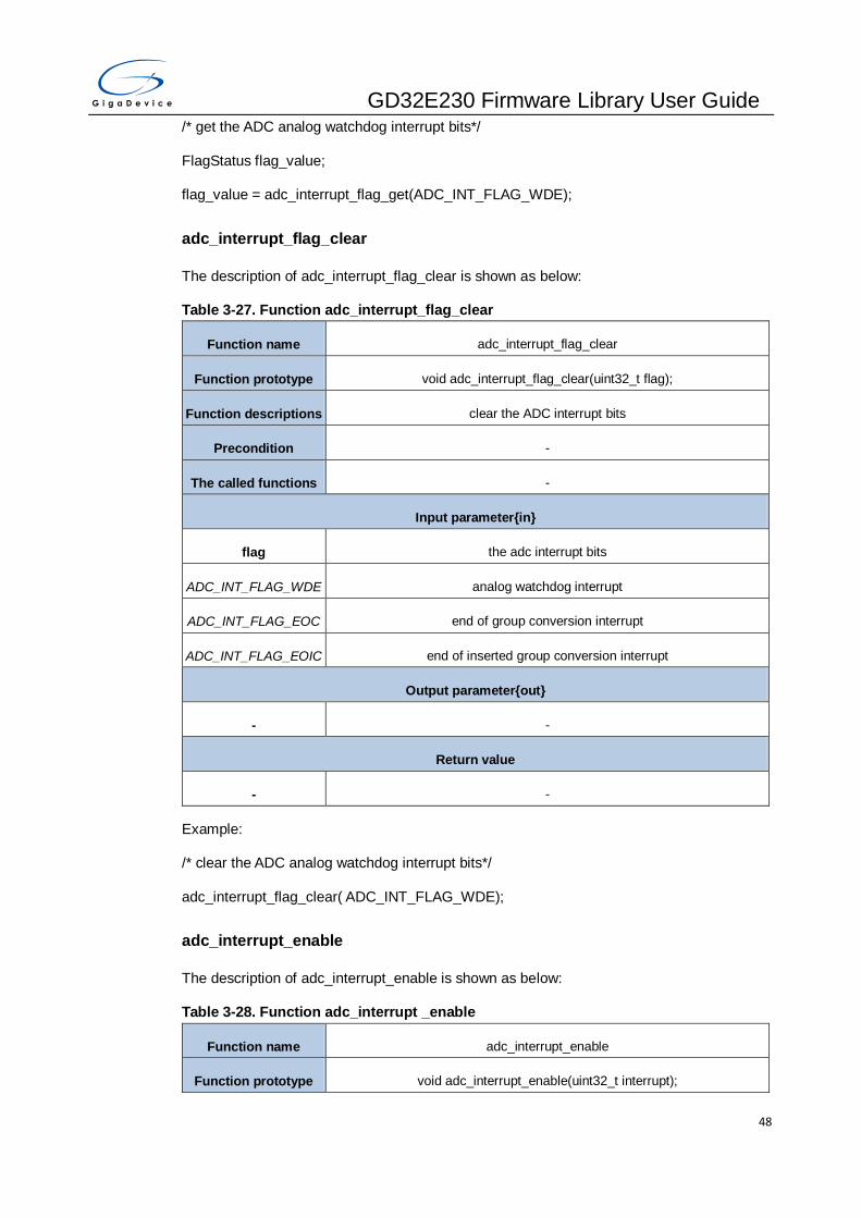
GD32E230 Firmware Library User Guide
48
/* get the ADC analog watchdog interrupt bits*/
FlagStatus flag_value;
flag_value = adc_interrupt_flag_get(ADC_INT_FLAG_WDE);
adc_interrupt_flag_clear
The description of adc_interrupt_flag_clear is shown as below:
Table 3-27. Function adc_interrupt_flag_clear
Function name adc_interrupt_flag_clear
Function prototype void adc_interrupt_flag_clear(uint32_t flag);
Function descriptions clear the ADC interrupt bits
Precondition -
The called functions -
Input parameter{in}
flag the adc interrupt bits
ADC_INT_FLAG_WDE analog watchdog interrupt
ADC_INT_FLAG_EOC end of group conversion interrupt
ADC_INT_FLAG_EOIC end of inserted group conversion interrupt
Output parameter{out}
- -
Return value
- -
Example:
/* clear the ADC analog watchdog interrupt bits*/
adc_interrupt_flag_clear( ADC_INT_FLAG_WDE);
adc_interrupt_enable
The description of adc_interrupt_enable is shown as below:
Table 3-28. Function adc_interrupt _enable
Function name adc_interrupt_enable
Function prototype void adc_interrupt_enable(uint32_t interrupt);

GD32E230 Firmware Library User Guide
49
Function descriptions enable ADC interrupt
Precondition -
The called functions -
Input parameter{in}
interrupt the adc interrupt
ADC_INT_WDE analog watchdog interrupt
ADC_INT_EOC end of group conversion interrupt
ADC_INT_EOIC end of inserted group conversion interrupt
Output parameter{out}
- -
Return value
- -
Example:
/* enable ADC analog watchdog interrupt */
adc_interrupt_enable(ADC_INT_WDE);
adc_interrupt_disable
The description of adc_interrupt_disable is shown as below:
Table 3-29. Function adc_interrupt_disable
Function name adc_interrupt_disable
Function prototype void adc_interrupt_disable(uint32_t interrupt);
Function descriptions Disable ADC interrupt
Precondition -
The called functions -
Input parameter{in}
interrupt the adc interrupt
ADC_INT_WDE analog watchdog interrupt
ADC_INT_EOC end of group conversion interrupt
ADC_INT_EOIC end of inserted group conversion interrupt

GD32E230 Firmware Library User Guide
50
Output parameter{out}
- -
Return value
- -
Example:
/* disable ADC interrupt */
adc_interrupt_disable( ADC_INT_WDE);
adc_watchdog_single_channel_enable
The description of adc_watchdog_single_channel_enable is shown as below:
Table 3-30. Function adc_watchdog_single_channel_enable
Function name adc_watchdog_single_channel_enable
Function prototype void adc_watchdog_single_channel_enable(uint8_t channel);
Function descriptions configure ADC analog watchdog single channel
Precondition -
The called functions -
Input parameter{in}
channel the selected ADC channel
ADC_CHANNEL_x ADC Channelx(x=0..9,16,17)
Output parameter{out}
- -
Return value
- -
Example:
/* configure ADC analog watchdog single channel */
adc_watchdog_single_channel_enable(ADC_CHANNEL_1);
adc_watchdog_group_channel_enable
The description of adc_watchdog_group_channel_enable is shown as below:
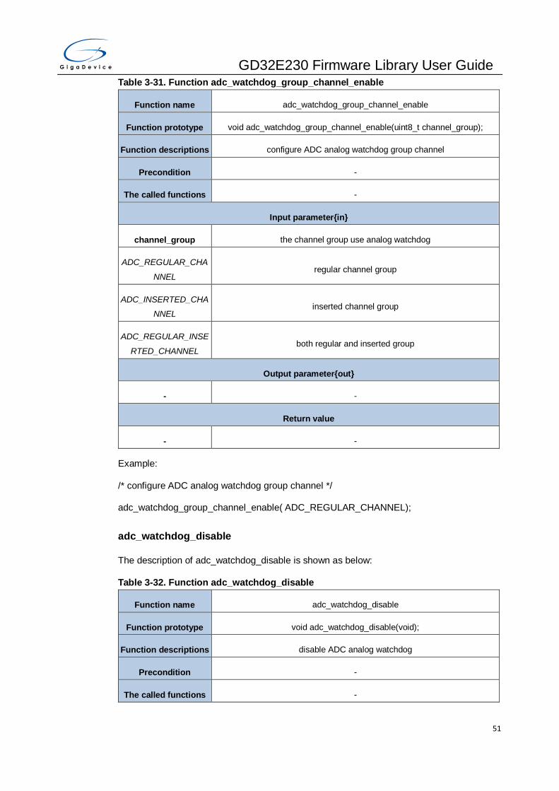
GD32E230 Firmware Library User Guide
51
Table 3-31. Function adc_watchdog_group_channel_enable
Function name adc_watchdog_group_channel_enable
Function prototype void adc_watchdog_group_channel_enable(uint8_t channel_group);
Function descriptions configure ADC analog watchdog group channel
Precondition -
The called functions -
Input parameter{in}
channel_group the channel group use analog watchdog
ADC_REGULAR_CHA
NNEL regular channel group
ADC_INSERTED_CHA
NNEL inserted channel group
ADC_REGULAR_INSE
RTED_CHANNEL both regular and inserted group
Output parameter{out}
- -
Return value
- -
Example:
/* configure ADC analog watchdog group channel */
adc_watchdog_group_channel_enable( ADC_REGULAR_CHANNEL);
adc_watchdog_disable
The description of adc_watchdog_disable is shown as below:
Table 3-32. Function adc_watchdog_disable
Function name adc_watchdog_disable
Function prototype void adc_watchdog_disable(void);
Function descriptions disable ADC analog watchdog
Precondition -
The called functions -

GD32E230 Firmware Library User Guide
52
Input parameter{in}
- -
Output parameter{out}
- -
Return value
- -
Example:
/* disable ADC0 analog watchdog */
adc_watchdog_disable(ADC0);
adc_watchdog_threshold_config
The description of adc_watchdog_threshold_config is shown as below:
Table 3-33. Function adc_watchdog_threshold_config
Function name adc_watchdog_threshold_config
Function prototype void adc_watchdog_threshold_config(uint16_t low_threshold, uint16_t
high_threshold);
Function descriptions configure ADC analog watchdog threshold
Precondition -
The called functions -
Input parameter{in}
low_threshold analog watchdog low threshold, 0..4095
Input parameter{in}
high_threshold analog watchdog high threshold, 0..4095
Output parameter{out}
- -
Return value
- -
Example:
/* configure ADC analog watchdog threshold */
adc_watchdog_threshold_config(0x0400, 0x0A00);
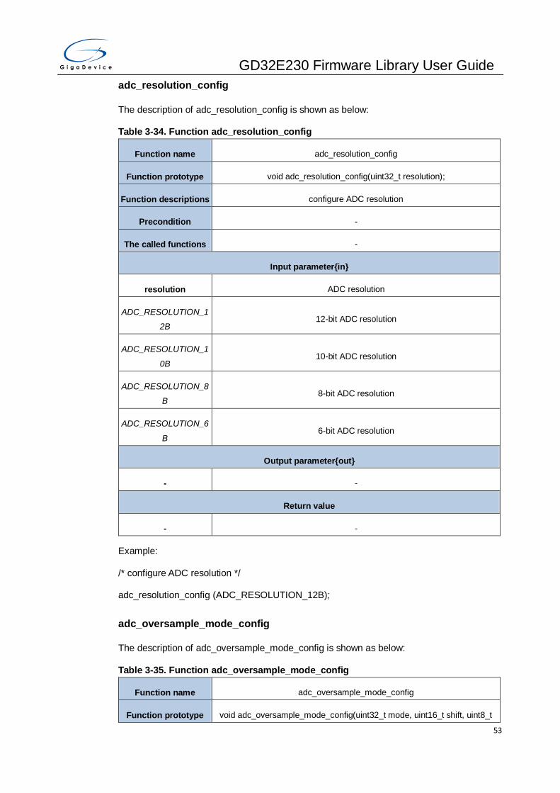
GD32E230 Firmware Library User Guide
53
adc_resolution_config
The description of adc_resolution_config is shown as below:
Table 3-34. Function adc_resolution_config
Function name adc_resolution_config
Function prototype void adc_resolution_config(uint32_t resolution);
Function descriptions configure ADC resolution
Precondition -
The called functions -
Input parameter{in}
resolution ADC resolution
ADC_RESOLUTION_1
2B 12-bit ADC resolution
ADC_RESOLUTION_1
0B 10-bit ADC resolution
ADC_RESOLUTION_8
B 8-bit ADC resolution
ADC_RESOLUTION_6
B 6-bit ADC resolution
Output parameter{out}
- -
Return value
- -
Example:
/* configure ADC resolution */
adc_resolution_config (ADC_RESOLUTION_12B);
adc_oversample_mode_config
The description of adc_oversample_mode_config is shown as below:
Table 3-35. Function adc_oversample_mode_config
Function name adc_oversample_mode_config
Function prototype void adc_oversample_mode_config(uint32_t mode, uint16_t shift, uint8_t
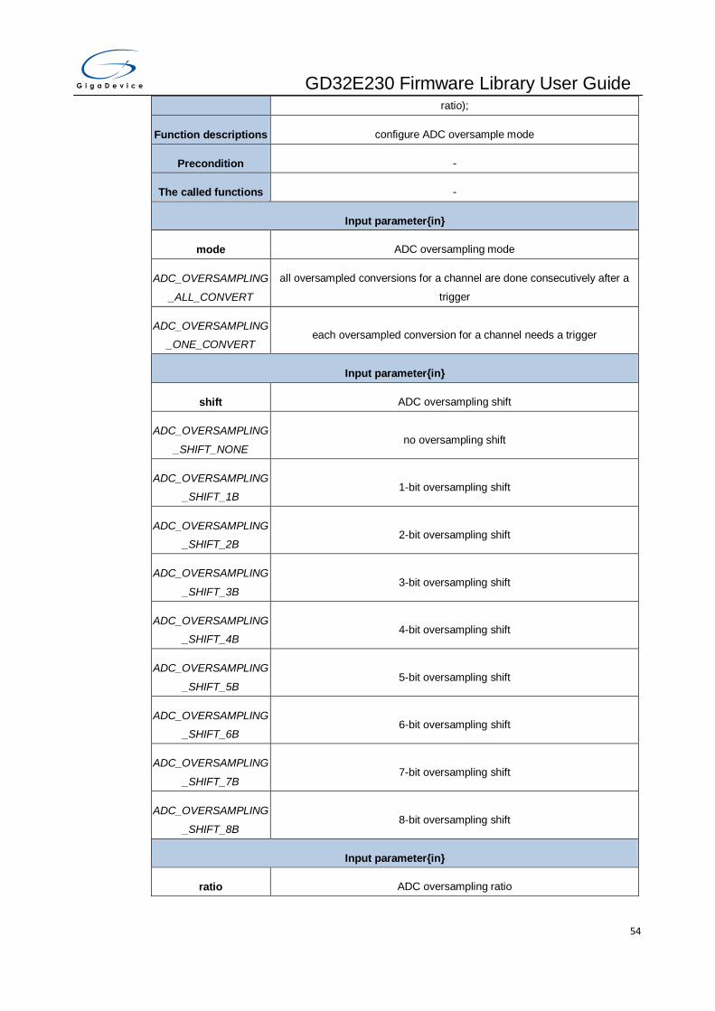
GD32E230 Firmware Library User Guide
54
ratio);
Function descriptions configure ADC oversample mode
Precondition -
The called functions -
Input parameter{in}
mode ADC oversampling mode
ADC_OVERSAMPLING
_ALL_CONVERT
all oversampled conversions for a channel are done consecutively after a
trigger
ADC_OVERSAMPLING
_ONE_CONVERT each oversampled conversion for a channel needs a trigger
Input parameter{in}
shift ADC oversampling shift
ADC_OVERSAMPLING
_SHIFT_NONE no oversampling shift
ADC_OVERSAMPLING
_SHIFT_1B 1-bit oversampling shift
ADC_OVERSAMPLING
_SHIFT_2B 2-bit oversampling shift
ADC_OVERSAMPLING
_SHIFT_3B 3-bit oversampling shift
ADC_OVERSAMPLING
_SHIFT_4B 4-bit oversampling shift
ADC_OVERSAMPLING
_SHIFT_5B 5-bit oversampling shift
ADC_OVERSAMPLING
_SHIFT_6B 6-bit oversampling shift
ADC_OVERSAMPLING
_SHIFT_7B 7-bit oversampling shift
ADC_OVERSAMPLING
_SHIFT_8B 8-bit oversampling shift
Input parameter{in}
ratio ADC oversampling ratio

GD32E230 Firmware Library User Guide
55
ADC_OVERSAMPLING
_RATIO_MUL2 oversampling ratio multiple 2
ADC_OVERSAMPLING
_RATIO_MUL4 oversampling ratio multiple 4
ADC_OVERSAMPLING
_RATIO_MUL8 oversampling ratio multiple 8
ADC_OVERSAMPLING
_RATIO_MUL16 oversampling ratio multiple 16
ADC_OVERSAMPLING
_RATIO_MUL32 oversampling ratio multiple 32
ADC_OVERSAMPLING
_RATIO_MUL64 oversampling ratio multiple 64
ADC_OVERSAMPLING
_RATIO_MUL128 oversampling ratio multiple 128
ADC_OVERSAMPLING
_RATIO_MUL256 oversampling ratio multiple 256
Output parameter{out}
- -
Return value
- -
Example:
/* configure ADC oversample mode: 16 times sample, 4 bits shift */
adc_oversample_mode_config(ADC_OVERSAMPLING_ALL_CONVERT,
ADC_OVERSAMPLING_SHIFT_4B, ADC_OVERSAMPLING_RATIO_MUL16);
adc_oversample_mode_enable
The description of adc_oversample_mode_enable is shown as below:
Table 3-36. Function adc_oversample_mode_enable
Function name adc_oversample_mode_enable
Function prototype void adc_oversample_mode_enable(void);
Function descriptions enable ADC oversample mode
Precondition -

GD32E230 Firmware Library User Guide
56
The called functions -
Input parameter{in}
- -
Output parameter{out}
- -
Return value
- -
Example:
/* enable ADC oversample mode */
adc_oversample_mode_enable ();
adc_oversample_mode_disable
The description of adc_oversample_mode_disable is shown as below:
Table 3-37. Function adc_oversample_mode_disable
Function name adc_oversample_mode_disable
Function prototype void adc_oversample_mode_disable(void);
Function descriptions disable ADC oversample mode
Precondition -
The called functions -
Input parameter{in}
- -
Output parameter{out}
- -
Return value
- -
Example:
/* disable ADC oversample mode */
adc_oversample_mode_disable ();
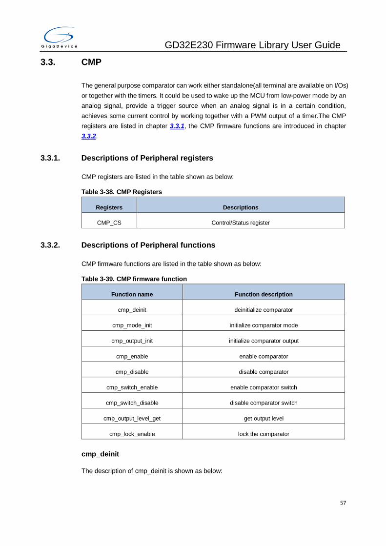
GD32E230 Firmware Library User Guide
57
3.3. CMP
The general purpose comparator can work either standalone(all terminal are available on I/Os)
or together with the timers. It could be used to wake up the MCU from low-power mode by an
analog signal, provide a trigger source when an analog signal is in a certain condition,
achieves some current control by working together with a PWM output of a timer.The CMP
registers are listed in chapter 3.3.1, the CMP firmware functions are introduced in chapter
3.3.2.
3.3.1. Descriptions of Peripheral registers
CMP registers are listed in the table shown as below:
Table 3-38. CMP Registers
Registers Descriptions
CMP_CS Control/Status register
3.3.2. Descriptions of Peripheral functions
CMP firmware functions are listed in the table shown as below:
Table 3-39. CMP firmware function
Function name Function description
cmp_deinit deinitialize comparator
cmp_mode_init initialize comparator mode
cmp_output_init initialize comparator output
cmp_enable enable comparator
cmp_disable disable comparator
cmp_switch_enable enable comparator switch
cmp_switch_disable disable comparator switch
cmp_output_level_get get output level
cmp_lock_enable lock the comparator
cmp_deinit
The description of cmp_deinit is shown as below:
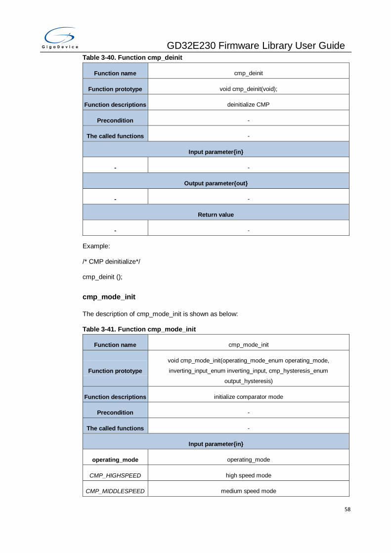
GD32E230 Firmware Library User Guide
58
Table 3-40. Function cmp_deinit
Function name cmp_deinit
Function prototype void cmp_deinit(void);
Function descriptions deinitialize CMP
Precondition -
The called functions -
Input parameter{in}
- -
Output parameter{out}
- -
Return value
- -
Example:
/* CMP deinitialize*/
cmp_deinit ();
cmp_mode_init
The description of cmp_mode_init is shown as below:
Table 3-41. Function cmp_mode_init
Function name cmp_mode_init
Function prototype
void cmp_mode_init(operating_mode_enum operating_mode,
inverting_input_enum inverting_input, cmp_hysteresis_enum
output_hysteresis)
Function descriptions initialize comparator mode
Precondition -
The called functions -
Input parameter{in}
operating_mode operating_mode
CMP_HIGHSPEED high speed mode
CMP_MIDDLESPEED medium speed mode

GD32E230 Firmware Library User Guide
59
CMP_LOWSPEED low speed mode
CMP_VERYLOWSPEE
D very-low speed mode
Input parameter{in}
inverting_input inverting_input
CMP_1_4VREFINT VREFINT *1/4 input
CMP_1_2VREFINT VREFINT *1/2 input
CMP_3_4VREFINT VREFINT *3/4 input
CMP_VREFINT VREFINT input
CMP_PA4 PA4 input
CMP_PA5 PA5 input
CMP_PA0 PA0 input
CMP_PA2 PA2 input
Input parameter{in}
output_hysteresis hysteresis
CMP_HYSTERESIS_N
O output no hysteresis
CMP_HYSTERESIS_L
OW output low hysteresis
CMP_HYSTERESIS_M
IDDLE output middle hysteresis
CMP_HYSTERESIS_HI
GH output high hysteresis
Output parameter{out}
- -
Return value
- -
Example:
/* CMP mode initialize*/
cmp_mode_init(CMP_HIGHSPEED,CMP_1_4VREFINT, CMP_HYSTERESIS_NO);
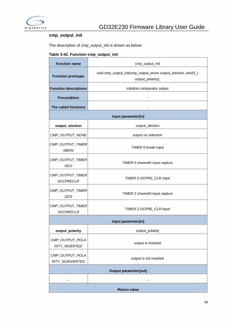
GD32E230 Firmware Library User Guide
60
cmp_output_init
The description of cmp_output_init is shown as below:
Table 3-42. Function cmp_output_init
Function name cmp_output_init
Function prototype void cmp_output_init(cmp_output_enum output_slection, uint32_t
output_polarity);
Function descriptions initialize comparator output
Precondition -
The called functions -
Input parameter{in}
output_slection output_slection
CMP_OUTPUT_NONE output no selection
CMP_OUTPUT_TIMER
0BKIN TIMER 0 break input
CMP_OUTPUT_TIMER
0IC0 TIMER 0 channel0 input capture
CMP_OUTPUT_TIMER
0OCPRECLR TIMER 0 OCPRE_CLR input
CMP_OUTPUT_TIMER
2IC0 TIMER 2 channel0 input capture
CMP_OUTPUT_TIMER
2OCPRECLR TIMER 2 OCPRE_CLR input
Input parameter{in}
output_polarity output_polarity
CMP_OUTPUT_POLA
RITY_INVERTED output is inverted
CMP_OUTPUT_POLA
RITY_NOINVERTED output is not inverted
Output parameter{out}
- -
Return value

GD32E230 Firmware Library User Guide
61
- -
Example:
/* CMP output initialize*/
cmp_output_init(CMP_OUTPUT_TIMER0BKIN,
CMP_OUTPUT_POLARITY_NOINVERTED);
cmp_enable
The description of cmp_enable is shown as below:
Table 3-43. Function can_fd_init
Function name cmp_enable
Function prototype void cmp_enable(void);
Function descriptions enable comparator
Precondition -
The called functions -
Input parameter{in}
- -
Output parameter{out}
- -
Return value
- -
Example:
/* enable CMP*/
cmp_enable();
cmp_disable
The description of cmp_disable is shown as below:
Table 3-44. Function cmp_disable
Function name cmp_disable
Function prototype void cmp_disable(void);
Function descriptions disable comparator
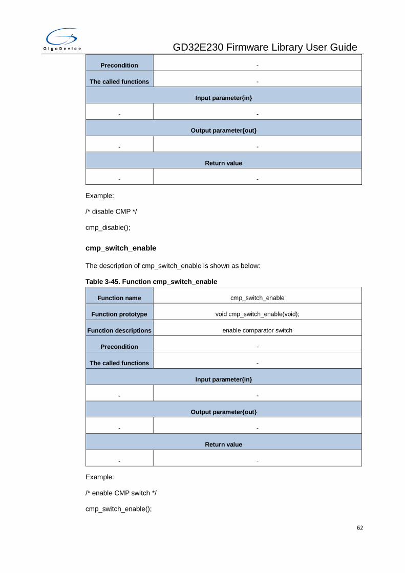
GD32E230 Firmware Library User Guide
62
Precondition -
The called functions -
Input parameter{in}
- -
Output parameter{out}
- -
Return value
- -
Example:
/* disable CMP */
cmp_disable();
cmp_switch_enable
The description of cmp_switch_enable is shown as below:
Table 3-45. Function cmp_switch_enable
Function name cmp_switch_enable
Function prototype void cmp_switch_enable(void);
Function descriptions enable comparator switch
Precondition -
The called functions -
Input parameter{in}
- -
Output parameter{out}
- -
Return value
- -
Example:
/* enable CMP switch */
cmp_switch_enable();

GD32E230 Firmware Library User Guide
63
cmp_switch_disable
The description of cmp_switch_disable is shown as below:
Table 3-46. Function cmp_switch_disable
Function name cmp_switch_disable
Function prototype void cmp_switch_disable(void);
Function descriptions disable comparator switch
Precondition -
The called functions -
Input parameter{in}
- -
Output parameter{out}
- -
Return value
- -
Example:
/* disable CMP switch */
cmp_switch_disable();
cmp_output_level_get
The description of cmp_output_level_get is shown as below:
Table 3-47. Function cmp_output_level_get
Function name cmp_output_level_get
Function prototype uint32_t cmp_output_level_get(void);
Function descriptions get output level
Precondition -
The called functions -
Input parameter{in}
- -
Output parameter{out}
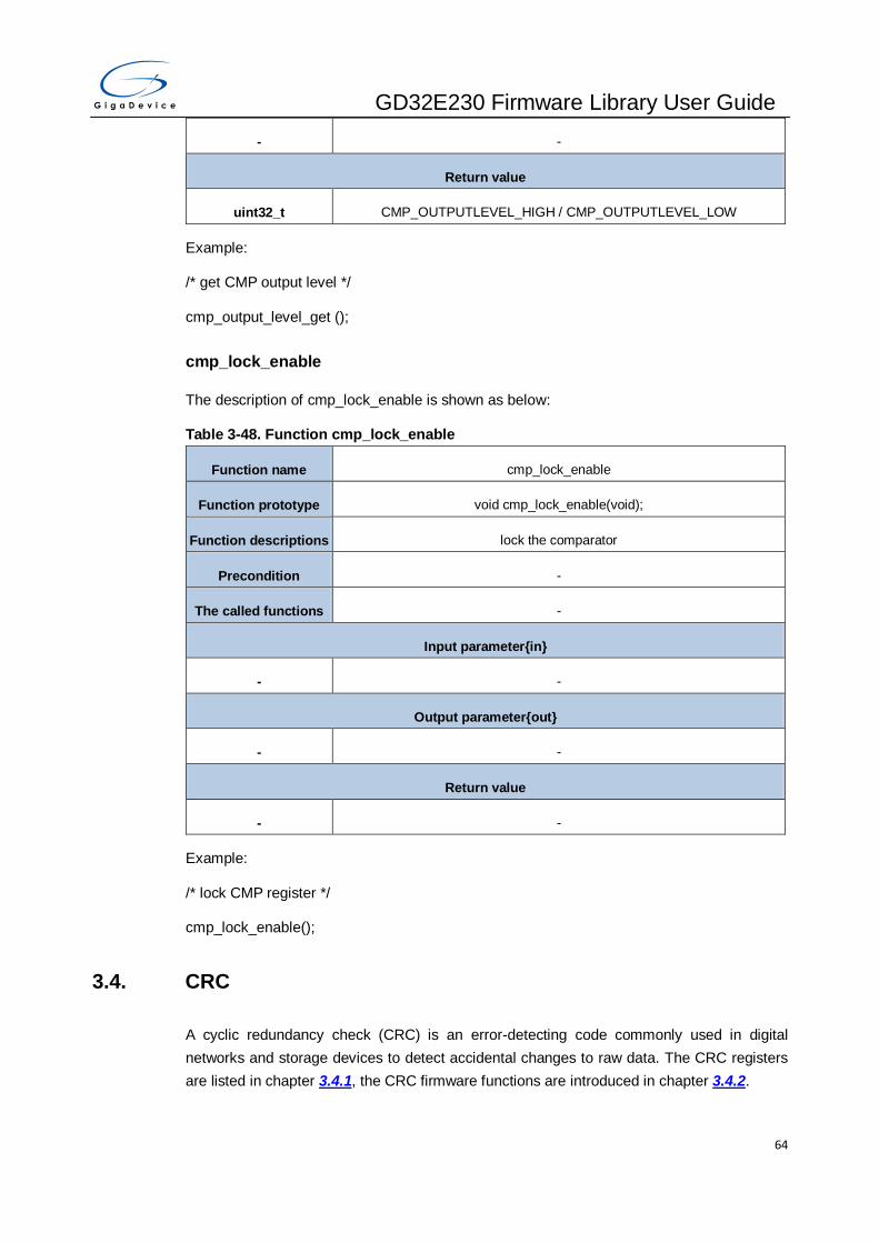
GD32E230 Firmware Library User Guide
64
- -
Return value
uint32_t CMP_OUTPUTLEVEL_HIGH / CMP_OUTPUTLEVEL_LOW
Example:
/* get CMP output level */
cmp_output_level_get ();
cmp_lock_enable
The description of cmp_lock_enable is shown as below:
Table 3-48. Function cmp_lock_enable
Function name cmp_lock_enable
Function prototype void cmp_lock_enable(void);
Function descriptions lock the comparator
Precondition -
The called functions -
Input parameter{in}
- -
Output parameter{out}
- -
Return value
- -
Example:
/* lock CMP register */
cmp_lock_enable();
3.4. CRC
A cyclic redundancy check (CRC) is an error-detecting code commonly used in digital
networks and storage devices to detect accidental changes to raw data. The CRC registers
are listed in chapter 3.4.1, the CRC firmware functions are introduced in chapter 3.4.2.

GD32E230 Firmware Library User Guide
65
3.4.1. Descriptions of Peripheral registers
CRC registers are listed in the table shown as below:
Table 3-49. CRC Registers
Registers Descriptions
CRC_DATA CRC data register
CRC_FDATA CRC free data register
CRC_CTL CRC control register
CRC_IDATA CRC initialization data register
CRC_POLY CRC polynomial register
3.4.2. Descriptions of Peripheral functions
CRC firmware functions are listed in the table shown as below:
Table 3-50. CRC firmware function
Function name Function description
crc_deinit deinit CRC calculation unit
crc_reverse_output_data_enable enable the reverse operation of output data
crc_reverse_output_data_disable disable the reverse operation of output data
crc_data_register_reset reset data register to the value of initializaiton data register
crc_data_register_read read the data register
crc_free_data_register_read read the free data register
crc_free_data_register_write write the free data register
crc_init_data_register_write write the initial value register
crc_input_data_reverse_config configure the CRC input data function
crc_polynomial_size_set onfigure the CRC size of polynomial function
crc_polynomial_set configure the CRC polynomial value function
crc_single_data_calculate CRC calculate a 32-bit data
crc_block_data_calculate CRC calculate a 32-bit data array

GD32E230 Firmware Library User Guide
66
crc_deinit
The description of crc_deinit is shown as below:
Table 3-51. Function crc_deinit
Function name crc_deinit
Function prototype void crc_deinit(void);
Function descriptions deinit CRC calculation unit
Precondition -
The called functions -
Input parameter{in}
- -
Output parameter{out}
- -
Return value
- -
Example:
/* reset crc */
crc_deinit();
crc_reverse_output_data_enable
The description of crc_reverse_output_data_enable is shown as below:
Table 3-52. Function crc_reverse_output_data_enable
Function name crc_reverse_output_data_enable
Function prototype void crc_reverse_output_data_enable (void);
Function descriptions enable the reverse operation of output data
Precondition -
The called functions -
Input parameter{in}
- -
Output parameter{out}

GD32E230 Firmware Library User Guide
67
- -
Return value
- -
Example:
/* enable CRC reverse operation of output data */
crc_reverse_output_data_enable ();
crc_reverse_output_data_disable
The description of crc_reverse_output_data_disable is shown as below:
Table 3-53. Function crc_reverse_output_data_disable
Function name crc_reverse_output_data_disable
Function prototype void crc_reverse_output_data_disable (void);
Function descriptions disable the reverse operation of output data
Precondition -
The called functions -
Input parameter{in}
- -
Output parameter{out}
- -
Return value
- -
Example:
/* disable crc reverse operation of output data */
crc_reverse_output_data_disable ();
crc_data_register_reset
The description of crc_data_register_reset is shown as below:
Table 3-54. Function crc_data_register_reset
Function name crc_data_register_reset
Function prototype void crc_data_register_reset(void);

GD32E230 Firmware Library User Guide
68
Function descriptions reset data register to the value of initializaiton data register
Precondition -
The called functions -
Input parameter{in}
- -
Output parameter{out}
- -
Return value
- -
Example:
/* reset crc data register */
crc_data_register_reset ();
crc_data_register_read
The description of crc_data_register_read is shown as below:
Table 3-55. Function crc_data_register_read
Function name crc_data_register_read
Function prototype uint32_t crc_data_register_read(void);
Function descriptions read the data register
Precondition -
The called functions -
Input parameter{in}
- -
Output parameter{out}
- -
Return value
uint32_t 32-bit value of the data register (0-0xFFFFFFFF)
Example:
/* read crc data register */

GD32E230 Firmware Library User Guide
69
uint32_t crc_value = 0;
crc_value = crc_data_register_read();
crc_free_data_register_read
The description of crc_free_data_register_read is shown as below:
Table 3-56. Function crc_free_data_register_read
Function name crc_free_data_register_read
Function prototype uint8_t crc_free_data_register_read(void);
Function descriptions read the free data register
Precondition -
The called functions -
Input parameter{in}
- -
Output parameter{out}
- -
Return value
uint8_t 8-bit value of the free data register (0-0xFF)
Example:
/* read crc free data register */
uint8_t crc_value = 0;
crc_value = crc_free_data_register_read();
crc_free_data_register_write
The description of crc_free_data_register_write is shown as below:
Table 3-57. Function crc_free_data_register_write
Function name crc_free_data_register_write
Function prototype void crc_free_data_register_write(uint8_t free_data);
Function descriptions write the free data register
Precondition -
The called functions -
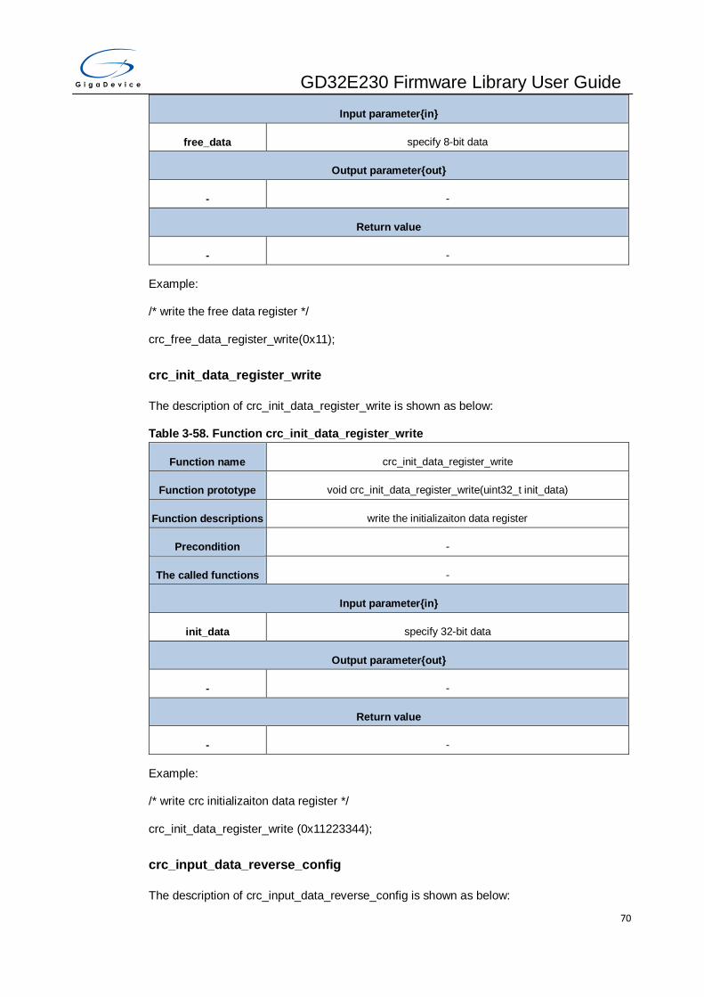
GD32E230 Firmware Library User Guide
70
Input parameter{in}
free_data specify 8-bit data
Output parameter{out}
- -
Return value
- -
Example:
/* write the free data register */
crc_free_data_register_write(0x11);
crc_init_data_register_write
The description of crc_init_data_register_write is shown as below:
Table 3-58. Function crc_init_data_register_write
Function name crc_init_data_register_write
Function prototype void crc_init_data_register_write(uint32_t init_data)
Function descriptions write the initializaiton data register
Precondition -
The called functions -
Input parameter{in}
init_data specify 32-bit data
Output parameter{out}
- -
Return value
- -
Example:
/* write crc initializaiton data register */
crc_init_data_register_write (0x11223344);
crc_input_data_reverse_config
The description of crc_input_data_reverse_config is shown as below:
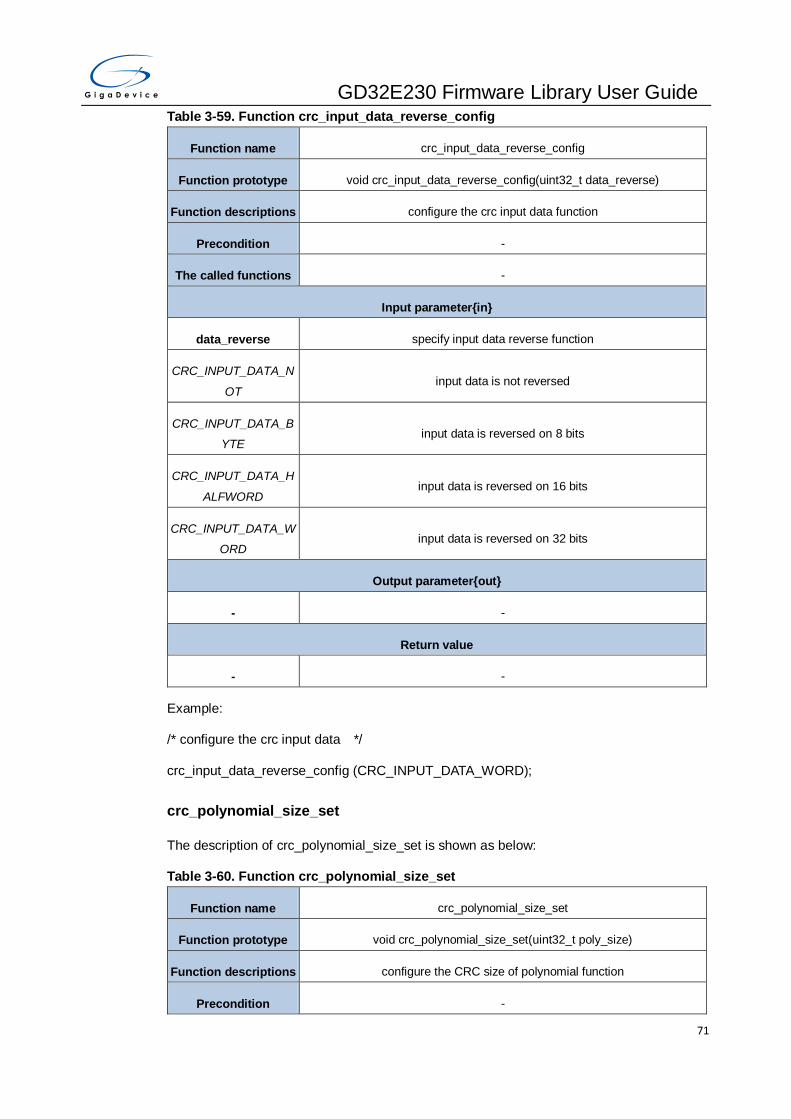
GD32E230 Firmware Library User Guide
71
Table 3-59. Function crc_input_data_reverse_config
Function name crc_input_data_reverse_config
Function prototype void crc_input_data_reverse_config(uint32_t data_reverse)
Function descriptions configure the crc input data function
Precondition -
The called functions -
Input parameter{in}
data_reverse specify input data reverse function
CRC_INPUT_DATA_N
OT input data is not reversed
CRC_INPUT_DATA_B
YTE input data is reversed on 8 bits
CRC_INPUT_DATA_H
ALFWORD input data is reversed on 16 bits
CRC_INPUT_DATA_W
ORD input data is reversed on 32 bits
Output parameter{out}
- -
Return value
- -
Example:
/* configure the crc input data */
crc_input_data_reverse_config (CRC_INPUT_DATA_WORD);
crc_polynomial_size_set
The description of crc_polynomial_size_set is shown as below:
Table 3-60. Function crc_polynomial_size_set
Function name crc_polynomial_size_set
Function prototype void crc_polynomial_size_set(uint32_t poly_size)
Function descriptions configure the CRC size of polynomial function
Precondition -

GD32E230 Firmware Library User Guide
72
The called functions -
Input parameter{in}
poly_size size of polynomial
CRC_CTL_PS_32 32-bit polynomial for CRC calculation
CRC_CTL_PS_16 16-bit polynomial for CRC calculation
CRC_CTL_PS_8 8-bit polynomial for CRC calculation
CRC_CTL_PS_7 7-bit polynomial for CRC calculation
Output parameter{out}
- -
Return value
- -
Example:
/* configure the CRC polynomial size*/
crc_polynomial_size_set (CRC_CTL_PS_7);
crc_polynomial_set
The description of crc_polynomial_set is shown as below:
Table 3-61. Function crc_polynomial_set
Function name crc_polynomial_set
Function prototype void crc_polynomial_set(uint32_t poly)
Function descriptions configure the CRC polynomial value function
Precondition -
The called functions -
Input parameter{in}
poly configurable polynomial value
Output parameter{out}
- -
Return value
- -

GD32E230 Firmware Library User Guide
73
Example:
/* configure the CRC polynomial value */
crc_polynomial_set (0x11223344);
crc_single_data_calculate
The description of crc_single_data_calculate is shown as below:
Table 3-62. Function crc_single_data_calculate
Function name crc_single_data_calculate
Function prototype uint32_t crc_single_data_calculate(uint32_t sdata);
Function descriptions CRC calculate a 32-bit data
Precondition -
The called functions -
Input parameter{in}
sdata specify 32-bit data
Output parameter{out}
- -
Return value
uint32_t 32-bit CRC calculate value (0-0xFFFFFFFF)
Example:
/* CRC calculate a 32-bit data */
uint32_t val = 0, valcrc = 0;
val = (uint32_t)0xabcd1234;
rcu_periph_clock_enable(RCU_CRC);
valcrc = crc_single_data_calculate(val);
crc_block_data_calculate
The description of crc_block_data_calculate is shown as below:
Table 3-63. Function crc_block_data_calculate
Function name crc_block_data_calculate
Function prototype uint32_t crc_block_data_calculate(uint32_t array[], uint32_t size);
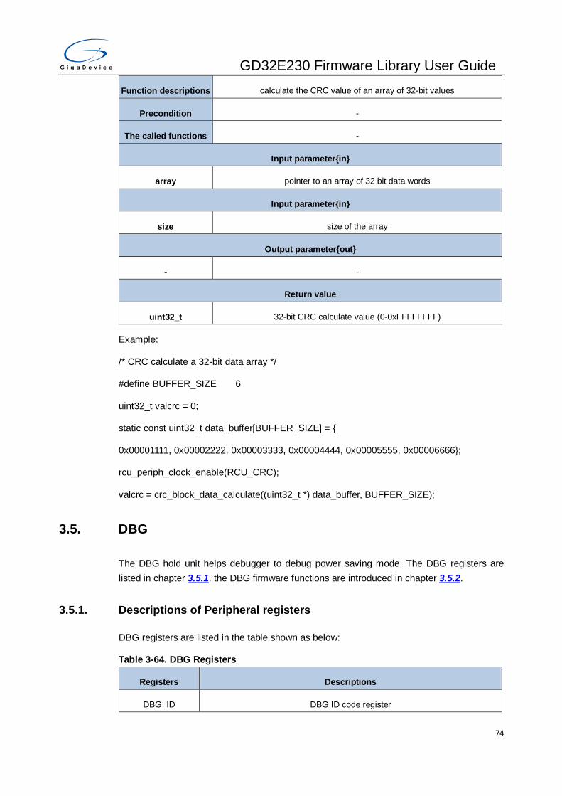
GD32E230 Firmware Library User Guide
74
Function descriptions calculate the CRC value of an array of 32-bit values
Precondition -
The called functions -
Input parameter{in}
array pointer to an array of 32 bit data words
Input parameter{in}
size size of the array
Output parameter{out}
- -
Return value
uint32_t 32-bit CRC calculate value (0-0xFFFFFFFF)
Example:
/* CRC calculate a 32-bit data array */
#define BUFFER_SIZE 6
uint32_t valcrc = 0;
static const uint32_t data_buffer[BUFFER_SIZE] = {
0x00001111, 0x00002222, 0x00003333, 0x00004444, 0x00005555, 0x00006666};
rcu_periph_clock_enable(RCU_CRC);
valcrc = crc_block_data_calculate((uint32_t *) data_buffer, BUFFER_SIZE);
3.5. DBG
The DBG hold unit helps debugger to debug power saving mode. The DBG registers are
listed in chapter 3.5.1. the DBG firmware functions are introduced in chapter 3.5.2.
3.5.1. Descriptions of Peripheral registers
DBG registers are listed in the table shown as below:
Table 3-64. DBG Registers
Registers Descriptions
DBG_ID DBG ID code register

GD32E230 Firmware Library User Guide
75
Registers Descriptions
DBG_CTL0 DBG control register0
DBG_CTL1 DBG control register1
3.5.2. Descriptions of Peripheral functions
DBG firmware functions are listed in the table shown as below:
Table 3-65. DBG firmware function
Function name Function description
dbg_deinit reset DBG register
dbg_id_get read DBG_ID code register
dbg_low_power_enable enable low power behavior when the MCU is in debug mode
dbg_low_power_disable disable low power behavior when the MCU is in debug mode
dbg_periph_enable enable peripheral behavior when the MCU is in debug mode
dbg_periph_disable disable peripheral behavior when the MCU is in debug mode
Enum dbg_periph_enum
Table 3-66. Enum dbg_periph_enum
Member name Function description
DBG_FWDGT_HOLD debug FWDGT kept when core is halted
DBG_WWDGT_HOLD debug WWDGT kept when core is halted
DBG_TIMER0_HOLD hold TIMER0 counter when core is halted
DBG_TIMER2_HOLD hold TIMER2 counter when core is halted
DBG_TIMER5_HOLD hold TIMER5 counter when core is halted
DBG_TIMER13_HOLD hold TIMER13 counter when core is halted
DBG_TIMER14_HOLD hold TIMER14 counter when core is halted
DBG_TIMER15_HOLD hold TIMER15 counter when core is halted
DBG_TIMER16_HOLD hold TIMER16 counter when core is halted
DBG_I2C0_HOLD hold I2C0 smbus when core is halted
DBG_I2C1_HOLD hold I2C1 smbus when core is halted

GD32E230 Firmware Library User Guide
76
DBG_RTC_HOLD hold RTC counter when core is halted
dbg_deinit
The description of dbg_deinit is shown as below:
Table 3-67. Function dbg_deinit
Function name dbg_deinit
Function prototype void dbg_deinit (void);
Function descriptions deinitialize the DBG
Precondition -
The called functions -
Input parameter{in}
- -
Output parameter{out}
- -
Return value
- -
Example:
/* deinitialize the DBG*/
dbg_deinit();
dbg_id_get
The description of dbg_id_get is shown as below:
Table 3-68. Function dbg_id_get
Function name dbg_id_get
Function prototype uint32_t dbg_id_get(void);
Function descriptions Read DBG_ID code register
Precondition -
The called functions -
Input parameter{in}
- -

GD32E230 Firmware Library User Guide
77
Output parameter{out}
- -
Return value
uint32_t DBG_ID code (0-0xFFFFFFFF)
Example:
/* read DBG_ID code register */
uint32_t id_value = 0;
id_value = dbg_id_get();
dbg_low_power_enable
The description of dbg_low_power_enable is shown as below:
Table 3-69. Function dbg_low_power_enable
Function name dbg_low_power_enable
Function prototype void dbg_low_power_enable(uint32_t dbg_low_power);
Function descriptions Enable low power behavior when the mcu is in debug mode
Precondition -
The called functions -
Input parameter{in}
dbg_low_power low power mode
DBG_LOW_POWER_S
LEEP keep debugger connection during sleep mode
DBG_LOW_POWER_D
EEPSLEEP keep debugger connection during deepsleep mode
DBG_LOW_POWER_S
TANDBY keep debugger connection during standby mode
Output parameter{out}
- -
Return value
- -
Example:

GD32E230 Firmware Library User Guide
78
/* enable low power behavior when the mcu is in debug mode */
dbg_low_power_enable(DBG_LOW_POWER_SLEEP);
dbg_low_power_disable
The description of dbg_low_power_disable is shown as below:
Table 3-70. Function dbg_low_power_disable
Function name dbg_low_power_disable
Function prototype void dbg_low_power_disable(uint32_t dbg_low_power);
Function descriptions Disable low power behavior when the mcu is in debug mode
Precondition -
The called functions -
Input parameter{in}
dbg_low_power low power mode
DBG_LOW_POWER_S
LEEP keep debugger connection during sleep mode
DBG_LOW_POWER_D
EEPSLEEP keep debugger connection during deepsleep mode
DBG_LOW_POWER_S
TANDBY keep debugger connection during standby mode
Output parameter{out}
- -
Return value
- -
Example:
/* disable low power behavior when the mcu is in debug mode */
dbg_low_power_disable(DBG_LOW_POWER_SLEEP);
dbg_periph_enable
The description of dbg_periph_enable is shown as below:
Table 3-71. Function dbg_periph_enable
Function name dbg_periph_enable

GD32E230 Firmware Library User Guide
79
Function prototype void dbg_periph_enable(dbg_periph_enum dbg_periph);
Function descriptions Enable peripheral behavior when the mcu is in debug mode
Precondition -
The called functions -
Input parameter{in}
dbg_periph Peripheral refer to Table 3-66. Enum dbg_periph_enum
DBG_FWDGT_HOLD debug FWDGT kept when core is halted
DBG_WWDGT_HOLD debug WWDGT kept when core is halted
DBG_TIMERx_HOLD x=0,2,5,13,14,15,16, hold TIMERx counter when core is halted
DBG_I2Cx_HOLD x=0,1, hold I2Cx smbus when core is halted
DBG_RTC_HOLD hold RTC counter when core is halted
Output parameter{out}
- -
Return value
- -
Example:
/* enable peripheral behavior when the mcu is in debug mode */
dbg_periph_enable(DBG_TIMER0_HOLD);
dbg_periph_disable
The description of dbg_periph_disable is shown as below:
Table 3-72. Function dbg_periph_disable
Function name dbg_periph_disable
Function prototype void dbg_periph_disable(dbg_periph_enum dbg_periph);
Function descriptions Disable peripheral behavior when the mcu is in debug mode
Precondition -
The called functions -
Input parameter{in}
dbg_periph peripheral refer to Table 3-66. Enum dbg_periph_enum

GD32E230 Firmware Library User Guide
80
DBG_FWDGT_HOLD debug FWDGT kept when core is halted
DBG_WWDGT_HOLD debug WWDGT kept when core is halted
DBG_TIMERx_HOLD x=0,2,5,13,14,15,16, hold TIMERx counter when core is halted
DBG_I2Cx_HOLD x=0,1, hold I2Cx smbus when core is halted
DBG_RTC_HOLD hold RTC counter when core is halted
Output parameter{out}
- -
Return value
- -
Example:
/* disable peripheral behavior when the mcu is in debug mode */
dbg_periph_disable(DBG_TIMER0_HOLD);
3.6. DMA
The direct memory access (DMA) controller provides a hardware method of transferring data
between peripherals and/or memory without intervention from the CPU, thereby freeing up
bandwidth for other system functions. The DMA registers are listed in chapter 3.6.1, the DMA
firmware functions are introduced in chapter 3.6.2.
3.6.1. Descriptions of Peripheral registers
DMA registers are listed in the table shown as below:
Table 3-73. DMA Registers
Registers Descriptions
DMA_INTF Interrupt flag register
DMA_INTC Interrupt flag clear register
DMA_CHxCTL
(x=0..4) Channel x control register
DMA_CHxCNT
(x=0..4) Channel x counter register
DMA_CHxPADDR
(x=0..4) Channel x peripheral base address register
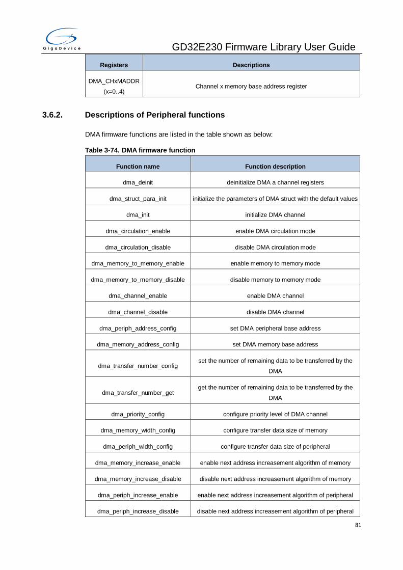
GD32E230 Firmware Library User Guide
81
Registers Descriptions
DMA_CHxMADDR
(x=0..4) Channel x memory base address register
3.6.2. Descriptions of Peripheral functions
DMA firmware functions are listed in the table shown as below:
Table 3-74. DMA firmware function
Function name Function description
dma_deinit deinitialize DMA a channel registers
dma_struct_para_init initialize the parameters of DMA struct with the default values
dma_init initialize DMA channel
dma_circulation_enable enable DMA circulation mode
dma_circulation_disable disable DMA circulation mode
dma_memory_to_memory_enable enable memory to memory mode
dma_memory_to_memory_disable disable memory to memory mode
dma_channel_enable enable DMA channel
dma_channel_disable disable DMA channel
dma_periph_address_config set DMA peripheral base address
dma_memory_address_config set DMA memory base address
dma_transfer_number_config set the number of remaining data to be transferred by the
DMA
dma_transfer_number_get get the number of remaining data to be transferred by the
DMA
dma_priority_config configure priority level of DMA channel
dma_memory_width_config configure transfer data size of memory
dma_periph_width_config configure transfer data size of peripheral
dma_memory_increase_enable enable next address increasement algorithm of memory
dma_memory_increase_disable disable next address increasement algorithm of memory
dma_periph_increase_enable enable next address increasement algorithm of peripheral
dma_periph_increase_disable disable next address increasement algorithm of peripheral
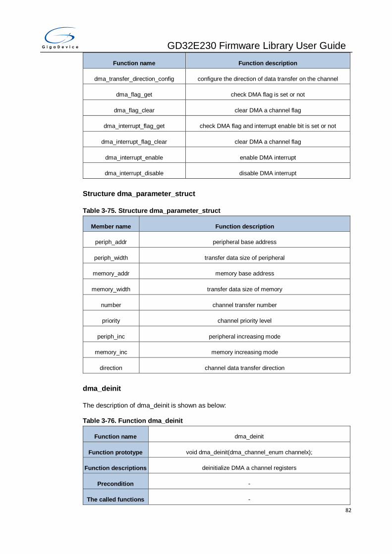
GD32E230 Firmware Library User Guide
82
Function name Function description
dma_transfer_direction_config configure the direction of data transfer on the channel
dma_flag_get check DMA flag is set or not
dma_flag_clear clear DMA a channel flag
dma_interrupt_flag_get check DMA flag and interrupt enable bit is set or not
dma_interrupt_flag_clear clear DMA a channel flag
dma_interrupt_enable enable DMA interrupt
dma_interrupt_disable disable DMA interrupt
Structure dma_parameter_struct
Table 3-75. Structure dma_parameter_struct
Member name Function description
periph_addr peripheral base address
periph_width transfer data size of peripheral
memory_addr memory base address
memory_width transfer data size of memory
number channel transfer number
priority channel priority level
periph_inc peripheral increasing mode
memory_inc memory increasing mode
direction channel data transfer direction
dma_deinit
The description of dma_deinit is shown as below:
Table 3-76. Function dma_deinit
Function name dma_deinit
Function prototype void dma_deinit(dma_channel_enum channelx);
Function descriptions deinitialize DMA a channel registers
Precondition -
The called functions -
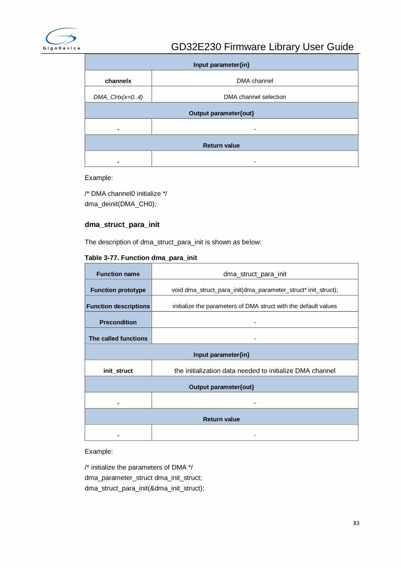
GD32E230 Firmware Library User Guide
83
Input parameter{in}
channelx DMA channel
DMA_CHx(x=0..4) DMA channel selection
Output parameter{out}
- -
Return value
- -
Example:
/* DMA channel0 initialize */
dma_deinit(DMA_CH0);
dma_struct_para_init
The description of dma_struct_para_init is shown as below:
Table 3-77. Function dma_para_init
Function name dma_struct_para_init
Function prototype void dma_struct_para_init(dma_parameter_struct* init_struct);
Function descriptions initialize the parameters of DMA struct with the default values
Precondition -
The called functions -
Input parameter{in}
init_struct the initialization data needed to initialize DMA channel
Output parameter{out}
- -
Return value
- -
Example:
/* initialize the parameters of DMA */
dma_parameter_struct dma_init_struct;
dma_struct_para_init(&dma_init_struct);

GD32E230 Firmware Library User Guide
84
dma_init
The description of dma_init is shown as below:
Table 3-78. Function dma_init
Function name dma_init
Function prototype void dma_init(dma_channel_enum channelx, dma_parameter_struct
init_struct);
Function descriptions initialize DMA channel
Precondition -
The called functions -
Input parameter{in}
channelx DMA channel
DMA_CHx( x=0..4) DMA channel selection
Input parameter{in}
init_struct Structure for initialization, the structure members can refer to Table 3-75.
Structure dma_parameter_struct
Output parameter{out}
- -
Return value
- -
Example:
/* DMA channel0 initialize */
dma_parameter_struct dma_init_struct;
dma_init_struct.direction = DMA_PERIPHERAL_TO_MEMORY;
dma_init_struct.memory_addr = (uint32_t)g_destbuf;
dma_init_struct.memory_inc = DMA_MEMORY_INCREASE_ENABLE;
dma_init_struct.memory_width = DMA_MEMORY_WIDTH_8BIT;
dma_init_struct.number = TRANSFER_NUM;
dma_init_struct.periph_addr = (uint32_t)BANK0_WRITE_START_ADDR;
dma_init_struct.periph_inc = DMA_PERIPH_INCREASE_ENABLE;
dma_init_struct.periph_width = DMA_PERIPHERAL_WIDTH_8BIT;
dma_init_struct.priority = DMA_PRIORITY_ULTRA_HIGH;
dma_init(DMA_CH0, dma_init_struct);

GD32E230 Firmware Library User Guide
85
dma_circulation_enable
The description of dma_circulation_enable is shown as below:
Table 3-79. Function dma_circulation_enable
Function name dma_circulation_enable
Function prototype void dma_circulation_enable(dma_channel_enum channelx);
Function descriptions enable DMA circulation mode
Precondition -
The called functions -
Input parameter{in}
channelx DMA channel
DMA_CHx( x=0..4) DMA channel selection
Output parameter{out}
- -
Return value
- -
Example:
/* enable DMA channel0 circulation mode */
dma_circulation_enable(DMA_CH0);
dma_circulation_disable
The description of dma_circulation_disable is shown as below:
Table 3-80. Function dma_circulation_disable
Function name dma_circulation_disable
Function prototype void dma_circulation_disable(dma_channel_enum channelx);
Function descriptions disable DMA circulation mode
Precondition -
The called functions -
Input parameter{in}
channelx DMA channel
DMA_CHx( x=0..4) DMA channel selection

GD32E230 Firmware Library User Guide
86
Output parameter{out}
- -
Return value
- -
Example:
/* disable DMA channel0 circulation mode */
dma_circulation_disable(DMA_CH0);
dma_memory_to_memory_enable
The description of dma_memory_to_memory_enable is shown as below:
Table 3-81. Function dma_memory_to_memory_enable
Function name dma_memory_to_memory_enable
Function prototype void dma_memory_to_memory_enable(dma_channel_enum channelx);
Function descriptions enable memory to memory mode
Precondition -
The called functions -
Input parameter{in}
channelx DMA channel
DMA_CHx( x=0..4) DMA channel selection
Output parameter{out}
- -
Return value
- -
Example:
/* enable DMA channel0 memory to memory mode */
dma_memory_to_memory_enable(DMA_CH0);
dma_memory_to_memory_disable
The description of dma_memory_to_memory_disable is shown as below:

GD32E230 Firmware Library User Guide
87
Table 3-82. Function dma_memory_to_memory_disable
Function name dma_memory_to_memory_disable
Function prototype void dma_memory_to_memory_disable(dma_channel_enum channelx);
Function descriptions disable memory to memory mode
Precondition -
The called functions -
Input parameter{in}
channelx DMA channel
DMA_CHx( x=0..4) DMA channel selection
Output parameter{out}
- -
Return value
- -
Example:
/*disable DMA channel0 memory to memory mode */
dma_memory_to_memory_disable(DMA_CH0);
dma_channel_enable
The description of dma_channel_enable is shown as below:
Table 3-83. Function dma_channel_enable
Function name dma_channel_enable
Function prototype void dma_channel_enable(dma_channel_enum channelx);
Function descriptions enable DMA channel
Precondition -
The called functions -
Input parameter{in}
channelx DMA channel
DMA_CHx(x=0..4) DMA channel selection
Output parameter{out}
- -

GD32E230 Firmware Library User Guide
88
Return value
- -
Example:
/* enable DMA channel0 */
dma_channel_enable(DMA_CH0);
dma_channel_disable
The description of dma_channel_disable is shown as below:
Table 3-84. Function dma_channel_disable
Function name dma_channel_disable
Function prototype void dma_channel_disable(dma_channel_enum channelx);
Function descriptions disable DMA channel
Precondition -
The called functions -
Input parameter{in}
channelx DMA channel
DMA_CHx( x=0..4) DMA channel selection
Output parameter{out}
- -
Return value
- -
Example:
/* disable DMA channel0 */
dma_channel_disable(DMA_CH0);
dma_periph_address_config
The description of dma_periph_address_config is shown as below:
Table 3-85. Function dma_periph_address_config
Function name dma_periph_address_config
Function prototype void dma_periph_address_config(dma_channel_enum channelx, uint32_t
address);

GD32E230 Firmware Library User Guide
89
Function descriptions set DMA peripheral base address
Precondition -
The called functions -
Input parameter{in}
channelx DMA channel
DMA_CHx(x=0..4) DMA channel selection
Input parameter{in}
address peripheral base address
Output parameter{out}
- -
Return value
- -
Example:
/* configure DMA channel0 periph address */
#define BANK0_WRITE_START_ADDR ((uint32_t)0x08004000)
dma_periph_address_config(DMA_CH0, BANK0_WRITE_START_ADDR);
dma_memory_address_config
The description of dma_memory_address_config is shown as below:
Table 3-86. Function dma_memory_address_config
Function name dma_memory_address_config
Function prototype void dma_memory_address_config(dma_channel_enum channelx, uint32_t
address);
Function descriptions set DMA memory base address
Precondition -
The called functions -
Input parameter{in}
channelx DMA channel
DMA_CHx(x=0..4) DMA channel selection
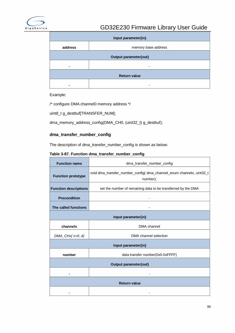
GD32E230 Firmware Library User Guide
90
Input parameter{in}
address memory base address
Output parameter{out}
- -
Return value
- -
Example:
/* configure DMA channel0 memory address */
uint8_t g_destbuf[TRANSFER_NUM];
dma_memory_address_config(DMA_CH0, (uint32_t) g_destbuf);
dma_transfer_number_config
The description of dma_transfer_number_config is shown as below:
Table 3-87. Function dma_transfer_number_config
Function name dma_transfer_number_config
Function prototype void dma_transfer_number_config( dma_channel_enum channelx, uint32_t
number);
Function descriptions set the number of remaining data to be transferred by the DMA
Precondition -
The called functions -
Input parameter{in}
channelx DMA channel
DMA_CHx( x=0..4) DMA channel selection
Input parameter{in}
number data transfer number(0x0-0xFFFF)
Output parameter{out}
- -
Return value
- -
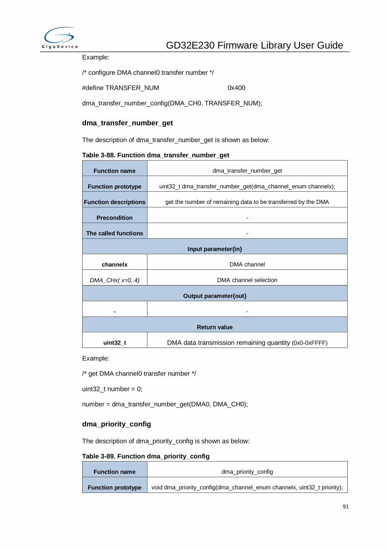
GD32E230 Firmware Library User Guide
91
Example:
/* configure DMA channel0 transfer number */
#define TRANSFER_NUM 0x400
dma_transfer_number_config(DMA_CH0, TRANSFER_NUM);
dma_transfer_number_get
The description of dma_transfer_number_get is shown as below:
Table 3-88. Function dma_transfer_number_get
Function name dma_transfer_number_get
Function prototype uint32_t dma_transfer_number_get(dma_channel_enum channelx);
Function descriptions get the number of remaining data to be transferred by the DMA
Precondition -
The called functions -
Input parameter{in}
channelx DMA channel
DMA_CHx( x=0..4) DMA channel selection
Output parameter{out}
- -
Return value
uint32_t DMA data transmission remaining quantity (0x0-0xFFFF)
Example:
/* get DMA channel0 transfer number */
uint32_t number = 0;
number = dma_transfer_number_get(DMA0, DMA_CH0);
dma_priority_config
The description of dma_priority_config is shown as below:
Table 3-89. Function dma_priority_config
Function name dma_priority_config
Function prototype void dma_priority_config(dma_channel_enum channelx, uint32_t priority);

GD32E230 Firmware Library User Guide
92
Function descriptions configure priority level of DMA channel
Precondition -
The called functions -
Input parameter{in}
channelx DMA channel
DMA_CHx(x=0..4) DMA channel selection
Input parameter{in}
priority priority Level of this channel
DMA_PRIORITY_LOW low priority
DMA_PRIORITY_MEDI
UM medium priority
DMA_PRIORITY_HIGH high priority
DMA_PRIORITY_ULTR
A_HIGH ultra high priority
Output parameter{out}
- -
Return value
- -
Example:
/* configure DMA channel0 priority */
dma_priority_config(DMA_CH0, DMA_PRIORITY_ULTRA_HIGH);
dma_memory_width_config
The description of dma_memory_width_config is shown as below:
Table 3-90. Function dma_memory_width_config
Function name dma_memory_width_config
Function prototype void dma_memory_width_config( dma_channel_enum channelx, uint32_t
mwidth);
Function descriptions configure transfer data size of memory
Precondition -

GD32E230 Firmware Library User Guide
93
The called functions -
Input parameter{in}
channelx DMA channel
DMA_CHx( x=0..4) DMA channel selection
Input parameter{in}
mwidth transfer data width of memory
DMA_MEMORY_WIDT
H_8BIT transfer data width of memory is 8-bit
DMA_MEMORY_WIDT
H_16BIT transfer data width of memory is 16-bit
DMA_MEMORY_WIDT
H_32BIT transfer data width of memory is 32-bit
Output parameter{out}
- -
Return value
- -
Example:
/* configure DMA channel0 memory width */
dma_memory_width_config(DMA_CH0, DMA_MEMORY_WIDTH_8BIT);
dma_periph_width_config
The description of dma_periph_width_config is shown as below:
Table 3-91. Function dma_periph_width_config
Function name dma_periph_width_config
Function prototype void dma_periph_width_config(dma_channel_enum channelx, uint32_t
pwidth);
Function descriptions configure transfer data width of peripheral
Precondition -
The called functions -
Input parameter{in}

GD32E230 Firmware Library User Guide
94
channelx DMA channel
DMA_CHx( x=0..4) DMA channel selection
Input parameter{in}
pwidth transfer data width of peripheral
DMA_PERIPHERAL_W
IDTH_8BIT transfer data width of peripheral is 8-bit
DMA_PERIPHERAL_W
IDTH_16BIT transfer data width of peripheral is 16-bit
DMA_PERIPHERAL_W
IDTH_32BIT transfer data width of peripheral is 32-bit
Output parameter{out}
- -
Return value
- -
Example:
/* configure DMA channel0 periph width */
dma_periph_width_config(DMA_CH0, DMA_PERIPHERAL_WIDTH_8BIT);
dma_memory_increase_enable
The description of dma_memory_increase_enable is shown as below:
Table 3-92. Function dma_memory_increase_enable
Function name dma_memory_increase_enable
Function prototype void dma_memory_increase_enable(dma_channel_enum channelx);
Function descriptions enable next address increasement algorithm of memory
Precondition -
The called functions -
Input parameter{in}
channelx DMA channel
DMA_CHx(x=0..4) DMA channel selection
Output parameter{out}
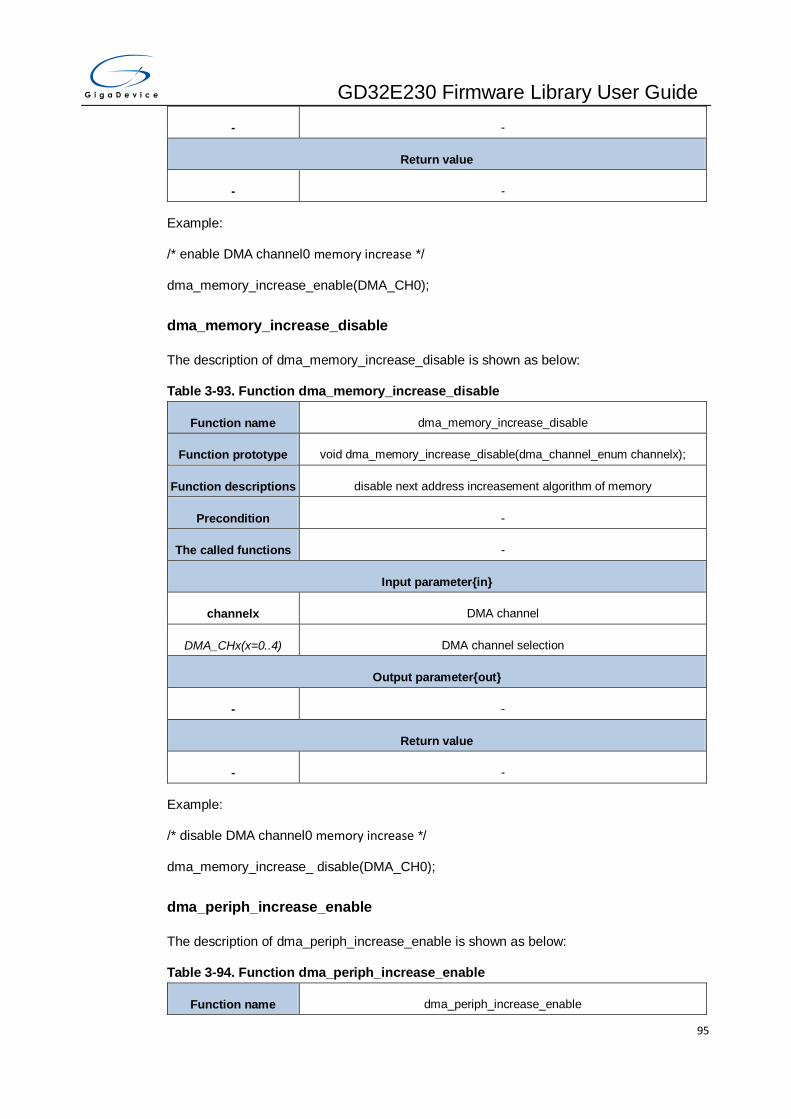
GD32E230 Firmware Library User Guide
95
- -
Return value
- -
Example:
/* enable DMA channel0 memory increase */
dma_memory_increase_enable(DMA_CH0);
dma_memory_increase_disable
The description of dma_memory_increase_disable is shown as below:
Table 3-93. Function dma_memory_increase_disable
Function name dma_memory_increase_disable
Function prototype void dma_memory_increase_disable(dma_channel_enum channelx);
Function descriptions disable next address increasement algorithm of memory
Precondition -
The called functions -
Input parameter{in}
channelx DMA channel
DMA_CHx(x=0..4) DMA channel selection
Output parameter{out}
- -
Return value
- -
Example:
/* disable DMA channel0 memory increase */
dma_memory_increase_ disable(DMA_CH0);
dma_periph_increase_enable
The description of dma_periph_increase_enable is shown as below:
Table 3-94. Function dma_periph_increase_enable
Function name dma_periph_increase_enable

GD32E230 Firmware Library User Guide
96
Function prototype void dma_periph_increase_enable(dma_channel_enum channelx);
Function descriptions enable next address increasement algorithm of peripheral
Precondition -
The called functions -
Input parameter{in}
channelx DMA channel
DMA_CHx(x=0..4) DMA channel selection
Output parameter{out}
- -
Return value
- -
Example:
/* enable DMA channel0 periph increase */
dma_periph_increase_enable(DMA_CH0);
dma_periph_increase_disable
The description of dma_periph_increase_disable is shown as below:
Table 3-95. Function dma_periph_increase_disable
Function name dma_periph_increase_disable
Function prototype void dma_periph_increase_disable(dma_channel_enum channelx);
Function descriptions disable next address increasement algorithm of peripheral
Precondition -
The called functions -
Input parameter{in}
channelx DMA channel
DMA_CHx(x=0..4) DMA channel selection
Output parameter{out}
- -
Return value

GD32E230 Firmware Library User Guide
97
- -
Example:
/* disable DMA channel0 periph increase */
dma_periph_increase_disable(DMA_CH0);
dma_transfer_direction_config
The description of dma_transfer_direction_config is shown as below:
Table 3-96. Function dma_transfer_direction_config
Function name dma_transfer_direction_config
Function prototype void dma_transfer_direction_config(dma_channel_enum channelx, uint32_t
direction);
Function descriptions configure the direction of data transfer on the channel
Precondition -
The called functions -
Input parameter{in}
channelx DMA channel
DMA_CHx( x=0..4) DMA channel selection
Input parameter{in}
direction specify the direction of data transfer
DMA_PERIPHERAL_T
O_MEMORY read from peripheral and write to memory
DMA_MEMORY_TO_P
ERIPHERAL read from memory and write to peripheral
Output parameter{out}
- -
Return value
- -
Example:
/* configure DMA channel0 transfer direction */
dma_transfer_direction_config(DMA_CH0, DMA_PERIPHERAL_TO_MEMORY);
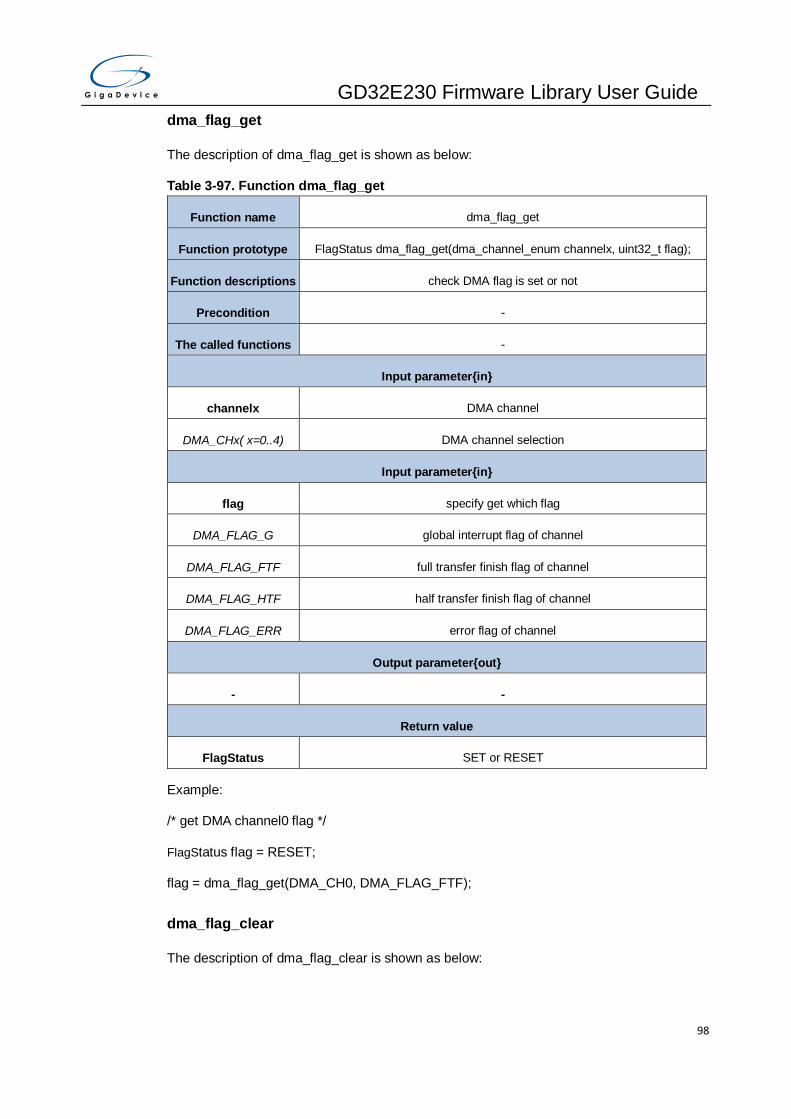
GD32E230 Firmware Library User Guide
98
dma_flag_get
The description of dma_flag_get is shown as below:
Table 3-97. Function dma_flag_get
Function name dma_flag_get
Function prototype FlagStatus dma_flag_get(dma_channel_enum channelx, uint32_t flag);
Function descriptions check DMA flag is set or not
Precondition -
The called functions -
Input parameter{in}
channelx DMA channel
DMA_CHx( x=0..4) DMA channel selection
Input parameter{in}
flag specify get which flag
DMA_FLAG_G global interrupt flag of channel
DMA_FLAG_FTF full transfer finish flag of channel
DMA_FLAG_HTF half transfer finish flag of channel
DMA_FLAG_ERR error flag of channel
Output parameter{out}
- -
Return value
FlagStatus SET or RESET
Example:
/* get DMA channel0 flag */
FlagStatus flag = RESET;
flag = dma_flag_get(DMA_CH0, DMA_FLAG_FTF);
dma_flag_clear
The description of dma_flag_clear is shown as below:

GD32E230 Firmware Library User Guide
99
Table 3-98. Function dma_flag_clear
Function name dma_flag_clear
Function prototype void dma_flag_clear(dma_channel_enum channelx, uint32_t flag);
Function descriptions clear DMA a channel flag
Precondition -
The called functions -
Input parameter{in}
channelx DMA channel
DMA_CHx( x=0..4) DMA channel selection
Input parameter{in}
flag specify get which flag
DMA_FLAG_G global interrupt flag of channel
DMA_FLAG_FTF full transfer finish flag of channel
DMA_FLAG_HTF half transfer finish flag of channel
DMA_FLAG_ERR error flag of channel
Output parameter{out}
- -
Return value
- -
Example:
/* clear DMA channel0 flag */
dma_flag_clear(DMA_CH0, DMA_FLAG_FTF);
dma_interrupt_flag_get
The description of dma_interrupt_flag_get is shown as below:
Table 3-99. Function dma_interrupt_flag_get
Function name dma_interrupt_flag_get
Function prototype FlagStatus dma_interrupt_flag_get(dma_channel_enum channelx, uint32_t
flag);
Function descriptions check DMA flag and interrupt enable bit is set or not

GD32E230 Firmware Library User Guide
100
Precondition -
The called functions -
Input parameter{in}
channelx DMA channel
DMA_CHx(x=0..4) DMA channel selection
Input parameter{in}
flag specify get which flag
DMA_INT_FLAG_FTF full transfer finish interrupt flag of channel
DMA_INT_FLAG_HTF half transfer finish interrupt flag of channel
DMA_INT_FLAG_ERR error interrupt flag of channel
Output parameter{out}
- -
Return value
FlagStatus SET or RESET
Example:
/* get DMA interrupt_flag */
if(dma_interrupt_flag_get(DMA_CH3, DMA_INT_FLAG_FTF)){
dma_interrupt_flag_clear(DMA_CH3, DMA_INT_FLAG_G);
}
dma_interrupt_flag_clear
The description of dma_interrupt_flag_clear is shown as below:
Table 3-100. Function dma_interrupt_flag_clear
Function name dma_interrupt_flag_clear
Function prototype void dma_interrupt_flag_clear(dma_channel_enum channelx, uint32_t flag);
Function descriptions clear DMA a channel flag
Precondition -
The called functions -
Input parameter{in}
channelx DMA channel

GD32E230 Firmware Library User Guide
101
DMA_CHx( x=0..4) DMA channel selection
Input parameter{in}
flag specify get which flag
DMA_INT_FLAG_G global interrupt flag of channel
DMA_INT_FLAG_FTF full transfer finish interrupt flag of channel
DMA_INT_FLAG_HTF half transfer finish interrupt flag of channel
DMA_INT_FLAG_ERR error interrupt flag of channel
Output parameter{out}
- -
Return value
- -
Example:
/* get DMA interrupt_flag */
if(dma_interrupt_flag_get(DMA_CH3, DMA_INT_FLAG_FTF)){
dma_interrupt_flag_clear(DMA_CH3, DMA_INT_FLAG_G);
}
dma_interrupt_enable
The description of dma_interrupt_enable is shown as below:
Table 3-101. Function dma_interrupt_enable
Function name dma_interrupt_enable
Function prototype void dma_interrupt_enable(dma_channel_enum channelx, uint32_t source);
Function descriptions enable DMA interrupt
Precondition -
The called functions -
Input parameter{in}
channelx DMA channel
DMA_CHx( x=0..4) DMA channel selection
Input parameter{in}
source DMA interrupt source

GD32E230 Firmware Library User Guide
102
DMA_INT_FTF full transfer finish interrupt of channel
DMA_INT_HTF half transfer finish interrupt of channel
DMA_INT_ERR error interrupt of channel
Output parameter{out}
- -
Return value
- -
Example:
/* enable DMA channel0 interrupt */
dma_interrupt_enable(DMA_CH0, DMA_INT_FTF);
dma_interrupt_disable
The description of dma_interrupt_disable is shown as below:
Table 3-102. Function dma_interrupt_disable
Function name dma_interrupt_disable
Function prototype void dma_interrupt_disable(dma_channel_enum channelx, uint32_t source);
Function descriptions disable DMA interrupt
Precondition -
The called functions -
Input parameter{in}
channelx DMA channel
DMA_CHx( x=0..4) DMA channel selection
Input parameter{in}
source DMA interrupt source
DMA_INT_FTF full transfer finish interrupt of channel
DMA_INT_HTF half transfer finish interrupt of channel
DMA_INT_ERR error interrupt of channel
Output parameter{out}
- -

GD32E230 Firmware Library User Guide
103
Return value
- -
Example:
/* disable DMA channel0 interrupt */
dma_interrupt_ disable(DMA_CH0, DMA_INT_FTF);
3.7. EXTI
EXTI is the interrupt/event controller in the MCU. It contains up to 21 independent edge
detectors and generates interrupt requests or events to the processer. The EXTI registers are
listed in chapter 3.7.1, the EXTI firmware functions are introduced in chapter 3.7.2.
3.7.1. Descriptions of Peripheral registers
EXTI registers are listed in the table shown as below:
Table 3-103. EXTI Registers
Registers Descriptions
EXTI_INTEN Interrupt enable register
EXTI_EVEN Event enable register
EXTI_RTEN Rising edge trigger enable register
EXTI_FTEN Falling edge trigger enable register
EXTI_SWIEV Software interrupt event register
EXTI_PD Pending register
3.7.2. Descriptions of Peripheral functions
EXTI firmware functions are listed in the table shown as below:
Table 3-104. EXTI firmware function
Function name Function description
exti_deinit reset EXTI
exti_init initialize EXTI line x
exti_interrupt_enable enable EXTI line x interrupt
exti_event_enable enable EXTI line x event
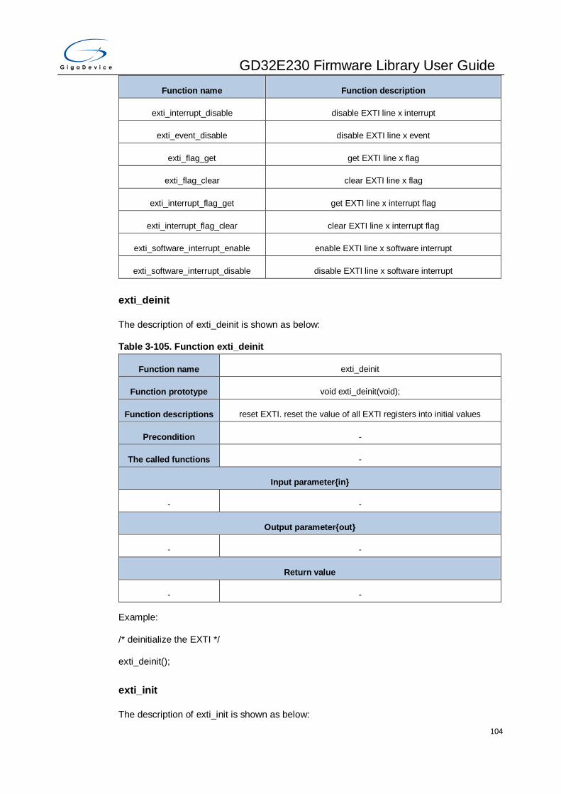
GD32E230 Firmware Library User Guide
104
Function name Function description
exti_interrupt_disable disable EXTI line x interrupt
exti_event_disable disable EXTI line x event
exti_flag_get get EXTI line x flag
exti_flag_clear clear EXTI line x flag
exti_interrupt_flag_get get EXTI line x interrupt flag
exti_interrupt_flag_clear clear EXTI line x interrupt flag
exti_software_interrupt_enable enable EXTI line x software interrupt
exti_software_interrupt_disable disable EXTI line x software interrupt
exti_deinit
The description of exti_deinit is shown as below:
Table 3-105. Function exti_deinit
Function name exti_deinit
Function prototype void exti_deinit(void);
Function descriptions reset EXTI. reset the value of all EXTI registers into initial values
Precondition -
The called functions -
Input parameter{in}
- -
Output parameter{out}
- -
Return value
- -
Example:
/* deinitialize the EXTI */
exti_deinit();
exti_init
The description of exti_init is shown as below:

GD32E230 Firmware Library User Guide
105
Table 3-106. Function exti_init
Function name exti_init
Function prototype void exti_init(exti_line_enum linex, exti_mode_enum mode,
exti_trig_type_enum trig_type);
Function descriptions initialize EXTI line x
Precondition -
The called functions -
Input parameter{in}
linex EXTI line x
EXTI_x x=0..17,19,21
Input parameter{in}
mode EXTI mode
EXTI_INTERRUPT interrupt mode
EXTI_EVENT event mode
Input parameter{in}
trig_type trigger type
EXTI_TRIG_RISING rising edge trigger
EXTI_TRIG_FALLING falling edge trigger
EXTI_TRIG_BOTH rising edge and falling edge trigger
Output parameter{out}
- -
Return value
- -
Example:
/* configure EXTI_0 */
exti_init(EXTI_0, EXTI_INTERRUPT, EXTI_TRIG_BOTH);
exti_interrupt_enable
The description of exti_interrupt_enable is shown as below:

GD32E230 Firmware Library User Guide
106
Table 3-107. Function exti_interrupt_enable
Function name exti_interrupt_enable
Function prototype void exti_interrupt_enable(exti_line_enum linex);
Function descriptions enable EXTI line x interrupt
Precondition -
The called functions -
Input parameter{in}
linex EXTI line x
EXTI_x x=0,1,2..27
Output parameter{out}
- -
Return value
- -
Example:
/* enable the interrupts from EXTI line 0 */
exti_interrupt_enable(EXTI_0);
exti_event_enable
The description of exti_event_enable is shown as below:
Table 3-108. Function exti_event_enable
Function name exti_event_enable
Function prototype void exti_event_enable(exti_line_enum linex);
Function descriptions enable EXTI line x event
Precondition -
The called functions -
Input parameter{in}
linex EXTI line x
EXTI_x x=0,1,2..27
Output parameter{out}

GD32E230 Firmware Library User Guide
107
- -
Return value
- -
Example:
/* enable the events from EXTI line 0 */
exti_event_enable(EXTI_0);
exti_interrupt_disable
The description of exti_interrupt_disable is shown as below:
Table 3-109. Function exti_interrupt_disable
Function name exti_interrupt_disable
Function prototype void exti_interrupt_disable(exti_line_enum linex);
Function descriptions disable EXTI line x interrupt
Precondition -
The called functions -
Input parameter{in}
linex EXTI line x
EXTI_x x=0,1,2..27
Output parameter{out}
- -
Return value
- -
Example:
/* disable the interrupts from EXTI line 0 */
exti_interrupt_disable(EXTI_0);
exti_event_disable
The description of exti_event_disable is shown as below:
Table 3-110. Function exti_event_disable
Function name exti_event_disable
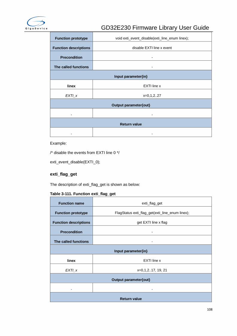
GD32E230 Firmware Library User Guide
108
Function prototype void exti_event_disable(exti_line_enum linex);
Function descriptions disable EXTI line x event
Precondition -
The called functions -
Input parameter{in}
linex EXTI line x
EXTI_x x=0,1,2..27
Output parameter{out}
- -
Return value
- -
Example:
/* disable the events from EXTI line 0 */
exti_event_disable(EXTI_0);
exti_flag_get
The description of exti_flag_get is shown as below:
Table 3-111. Function exti_flag_get
Function name exti_flag_get
Function prototype FlagStatus exti_flag_get(exti_line_enum linex);
Function descriptions get EXTI line x flag
Precondition -
The called functions -
Input parameter{in}
linex EXTI line x
EXTI_x x=0,1,2..17, 19, 21
Output parameter{out}
- -
Return value
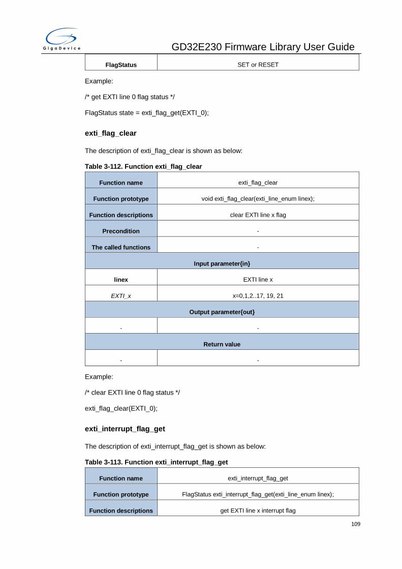
GD32E230 Firmware Library User Guide
109
FlagStatus SET or RESET
Example:
/* get EXTI line 0 flag status */
FlagStatus state = exti_flag_get(EXTI_0);
exti_flag_clear
The description of exti_flag_clear is shown as below:
Table 3-112. Function exti_flag_clear
Function name exti_flag_clear
Function prototype void exti_flag_clear(exti_line_enum linex);
Function descriptions clear EXTI line x flag
Precondition -
The called functions -
Input parameter{in}
linex EXTI line x
EXTI_x x=0,1,2..17, 19, 21
Output parameter{out}
- -
Return value
- -
Example:
/* clear EXTI line 0 flag status */
exti_flag_clear(EXTI_0);
exti_interrupt_flag_get
The description of exti_interrupt_flag_get is shown as below:
Table 3-113. Function exti_interrupt_flag_get
Function name exti_interrupt_flag_get
Function prototype FlagStatus exti_interrupt_flag_get(exti_line_enum linex);
Function descriptions get EXTI line x interrupt flag
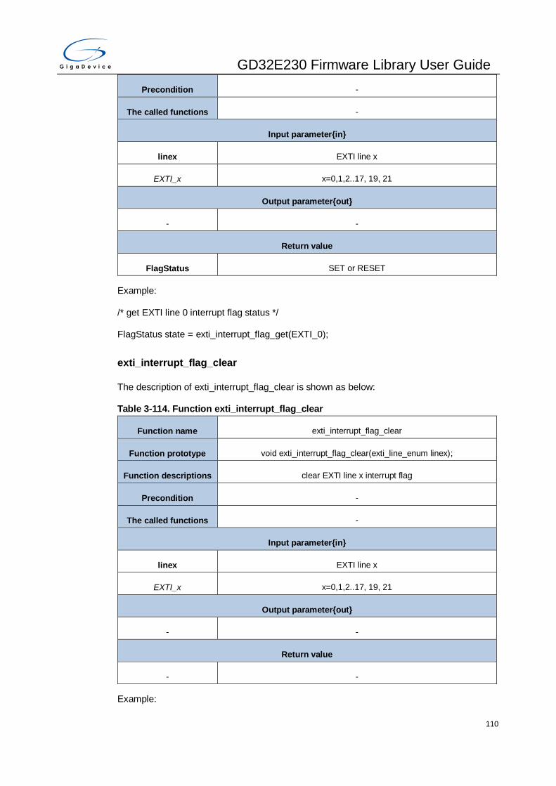
GD32E230 Firmware Library User Guide
110
Precondition -
The called functions -
Input parameter{in}
linex EXTI line x
EXTI_x x=0,1,2..17, 19, 21
Output parameter{out}
- -
Return value
FlagStatus SET or RESET
Example:
/* get EXTI line 0 interrupt flag status */
FlagStatus state = exti_interrupt_flag_get(EXTI_0);
exti_interrupt_flag_clear
The description of exti_interrupt_flag_clear is shown as below:
Table 3-114. Function exti_interrupt_flag_clear
Function name exti_interrupt_flag_clear
Function prototype void exti_interrupt_flag_clear(exti_line_enum linex);
Function descriptions clear EXTI line x interrupt flag
Precondition -
The called functions -
Input parameter{in}
linex EXTI line x
EXTI_x x=0,1,2..17, 19, 21
Output parameter{out}
- -
Return value
- -
Example:

GD32E230 Firmware Library User Guide
111
/* clear EXTI line 0 interrupt flag status */
exti_interrupt_flag_clear(EXTI_0);
exti_software_interrupt_enable
The description of exti_software_interrupt_enable is shown as below:
Table 3-115. Function exti_software_interrupt_enable
Function name exti_software_interrupt_enable
Function prototype void exti_software_interrupt_enable(exti_line_enum linex);
Function descriptions enable EXTI line x software interrupt
Precondition -
The called functions -
Input parameter{in}
linex EXTI line x
EXTI_x x=0,1,2..17, 19, 21
Output parameter{out}
- -
Return value
- -
Example:
/* enable EXTI line 0 software interrupt */
exti_software_interrupt_enable(EXTI_0);
exti_software_interrupt_disable
The description of exti_software_interrupt_disable is shown as below:
Table 3-116. Function exti_software_interrupt_disable
Function name exti_software_interrupt_disable
Function prototype void exti_software_interrupt_disable(exti_line_enum linex);
Function descriptions disable EXTI line x software interrupt
Precondition -
The called functions -

GD32E230 Firmware Library User Guide
112
Input parameter{in}
linex EXTI line x
EXTI_x x=0,1,2..17, 19, 21
Output parameter{out}
- -
Return value
- -
Example:
/* disable EXTI line 0 software interrupt */
exti_software_interrupt_disable(EXTI_0);
3.8. FMC
There is flash controller and option byte for GD32E230 series. The FMC registers are listed
in chapter 3.8.1 the FMC firmware functions are introduced in chapter 3.8.2.
3.8.1. Descriptions of Peripheral registers
FMC registers are listed in the table shown as below:
Table 3-117. FMC Registers
Registers Descriptions
FMC_WS FMC wait state register
FMC_KEY FMC unlock key register
FMC_OBKEY FMC option bytes unlock key register
FMC_STAT FMC status register
FMC_CTL FMC control register
FMC_ADDR FMC address register
FMC_OBSTAT FMC option bytes status register
FMC_WP FMC write protection register
FMC_PID FMC product ID register
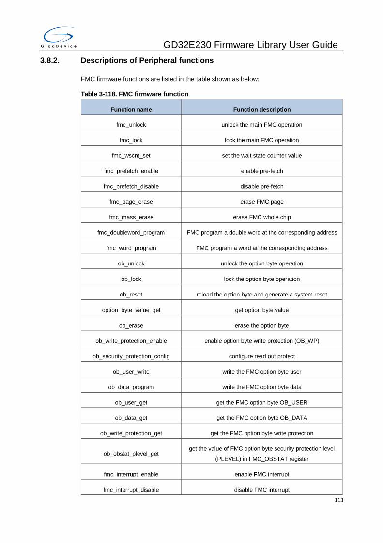
GD32E230 Firmware Library User Guide
113
3.8.2. Descriptions of Peripheral functions
FMC firmware functions are listed in the table shown as below:
Table 3-118. FMC firmware function
Function name Function description
fmc_unlock unlock the main FMC operation
fmc_lock lock the main FMC operation
fmc_wscnt_set set the wait state counter value
fmc_prefetch_enable enable pre-fetch
fmc_prefetch_disable disable pre-fetch
fmc_page_erase erase FMC page
fmc_mass_erase erase FMC whole chip
fmc_doubleword_program FMC program a double word at the corresponding address
fmc_word_program FMC program a word at the corresponding address
ob_unlock unlock the option byte operation
ob_lock lock the option byte operation
ob_reset reload the option byte and generate a system reset
option_byte_value_get get option byte value
ob_erase erase the option byte
ob_write_protection_enable enable option byte write protection (OB_WP)
ob_security_protection_config configure read out protect
ob_user_write write the FMC option byte user
ob_data_program write the FMC option byte data
ob_user_get get the FMC option byte OB_USER
ob_data_get get the FMC option byte OB_DATA
ob_write_protection_get get the FMC option byte write protection
ob_obstat_plevel_get get the value of FMC option byte security protection level
(PLEVEL) in FMC_OBSTAT register
fmc_interrupt_enable enable FMC interrupt
fmc_interrupt_disable disable FMC interrupt
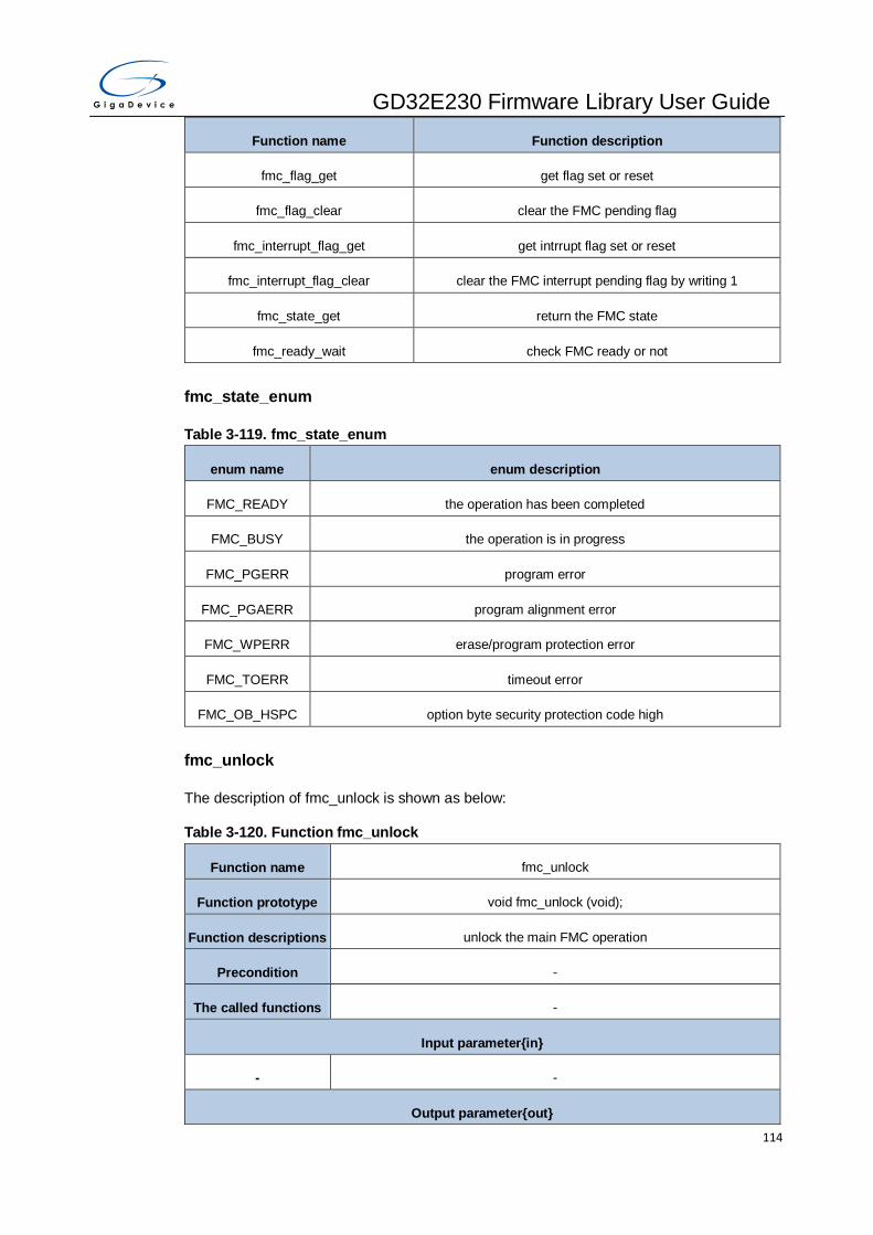
GD32E230 Firmware Library User Guide
114
Function name Function description
fmc_flag_get get flag set or reset
fmc_flag_clear clear the FMC pending flag
fmc_interrupt_flag_get get intrrupt flag set or reset
fmc_interrupt_flag_clear clear the FMC interrupt pending flag by writing 1
fmc_state_get return the FMC state
fmc_ready_wait check FMC ready or not
fmc_state_enum
Table 3-119. fmc_state_enum
enum name enum description
FMC_READY the operation has been completed
FMC_BUSY the operation is in progress
FMC_PGERR program error
FMC_PGAERR program alignment error
FMC_WPERR erase/program protection error
FMC_TOERR timeout error
FMC_OB_HSPC option byte security protection code high
fmc_unlock
The description of fmc_unlock is shown as below:
Table 3-120. Function fmc_unlock
Function name fmc_unlock
Function prototype void fmc_unlock (void);
Function descriptions unlock the main FMC operation
Precondition -
The called functions -
Input parameter{in}
- -
Output parameter{out}
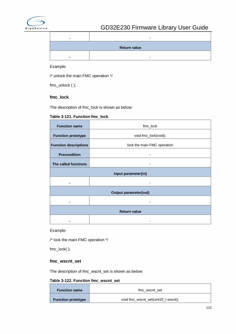
GD32E230 Firmware Library User Guide
115
- -
Return value
- -
Example:
/* unlock the main FMC operation */
fmc_unlock ( );
fmc_lock
The description of fmc_lock is shown as below:
Table 3-121. Function fmc_lock
Function name fmc_lock
Function prototype void fmc_lock(void);
Function descriptions lock the main FMC operation
Precondition -
The called functions -
Input parameter{in}
- -
Output parameter{out}
- -
Return value
- -
Example:
/* lock the main FMC operation */
fmc_lock( );
fmc_wscnt_set
The description of fmc_wscnt_set is shown as below:
Table 3-122. Function fmc_wscnt_set
Function name fmc_wscnt_set
Function prototype void fmc_wscnt_set(uint32_t wscnt);
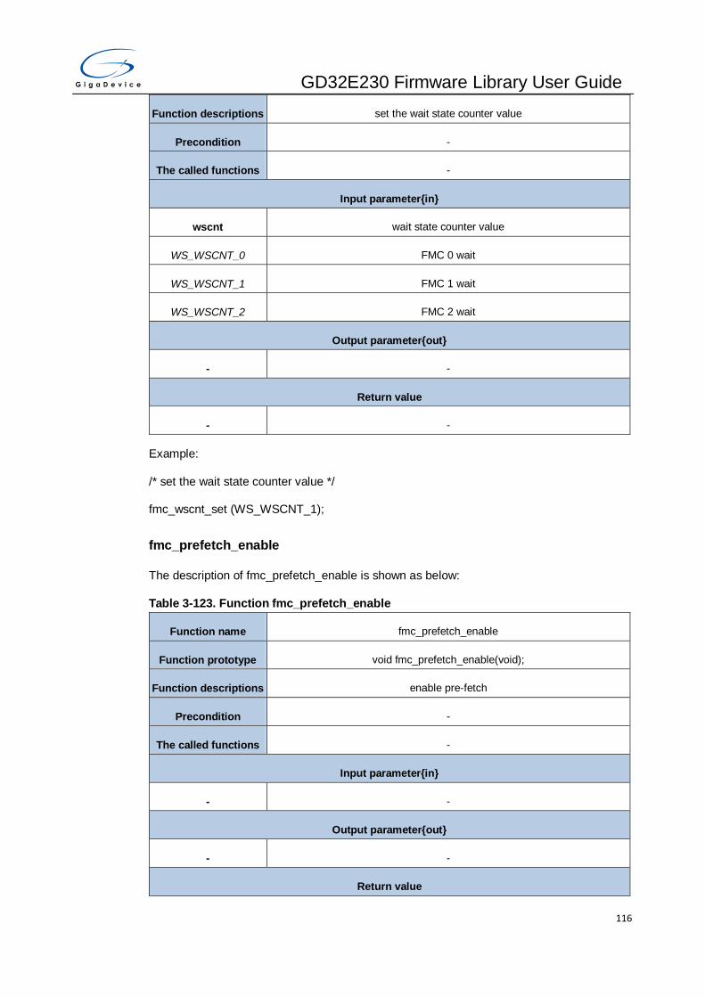
GD32E230 Firmware Library User Guide
116
Function descriptions set the wait state counter value
Precondition -
The called functions -
Input parameter{in}
wscnt wait state counter value
WS_WSCNT_0 FMC 0 wait
WS_WSCNT_1 FMC 1 wait
WS_WSCNT_2 FMC 2 wait
Output parameter{out}
- -
Return value
- -
Example:
/* set the wait state counter value */
fmc_wscnt_set (WS_WSCNT_1);
fmc_prefetch_enable
The description of fmc_prefetch_enable is shown as below:
Table 3-123. Function fmc_prefetch_enable
Function name fmc_prefetch_enable
Function prototype void fmc_prefetch_enable(void);
Function descriptions enable pre-fetch
Precondition -
The called functions -
Input parameter{in}
- -
Output parameter{out}
- -
Return value

GD32E230 Firmware Library User Guide
117
- -
Example:
/* enable pre-fetch */
fmc_prefetch_enable( );
fmc_prefetch_disable
The description of fmc_prefetch_disable is shown as below:
Table 3-124. Function fmc_prefetch_disable
Function name fmc_prefetch_disable
Function prototype void fmc_prefetch_disable (void);
Function descriptions disable pre-fetch
Precondition -
The called functions -
Input parameter{in}
- -
Output parameter{out}
- -
Return value
- -
Example:
/* disable pre-fetch */
fmc_prefetch_disable( );
fmc_page_erase
The description of fmc_page_erase is shown as below:
Table 3-125. Function fmc_page_erase
Function name fmc_page_erase
Function prototype fmc_state_enum fmc_page_erase(uint32_t page_address);
Function descriptions erase page
Precondition fmc_unlock

GD32E230 Firmware Library User Guide
118
The called functions fmc_ready_wait
Input parameter{in}
page_address the page address to be erased
Output parameter{out}
- -
Return value
fmc_state_enum state of FMC,the enum members can refer to members of the enum Table
3-119. fmc_state_enum
Example:
/* erase page */
fmc_state_enum state = fmc_page_erase ( 0x08004000);
fmc_mass_erase
The description of fmc_mass_erase is shown as below:
Table 3-126. Function fmc_mass_erase
Function name fmc_mass_erase
Function prototype fmc_state_enum fmc_mass_erase(void );
Function descriptions erase whole chip
Precondition fmc_unlock
The called functions fmc_ready_wait
Input parameter{in}
- -
Output parameter{out}
- -
Return value
fmc_state_enum state of FMC,the enum members can refer to members of the enum Table
3-119. fmc_state_enum
Example:
/* erase whole chip */
fmc_state_enum state = fmc_mass_erase ( );

GD32E230 Firmware Library User Guide
119
fmc_doubleword_program
The description of fmc_doubleword_program is shown as below:
Table 3-127. Function fmc_doubleword_program
Function name fmc_doubleword_program
Function prototype fmc_state_enum fmc_doubleword_program(uint32_t address, uint64_t
data);
Function descriptions program a double word at the corresponding address
Precondition fmc_unlock
The called functions fmc_ready_wait
Input parameter{in}
address the address to program
Input parameter{in}
data the data to program
Output parameter{out}
- -
Return value
fmc_state_enum state of FMC,the enum members can refer to members of the enum Table
3-119. fmc_state_enum
Example:
/* program a double word at the corresponding address */
fmc_state_enum fmc_state = fmc_doubleword_program( 0x08004000,0xaabbccddeeffgghh);
fmc_word_program
The description of fmc_word_program is shown as below:
Table 3-128. Function fmc_word_program
Function name fmc_word_program
Function prototype fmc_state_enum fmc_word_program(uint32_t address, uint32_t data);
Function descriptions program a word at the corresponding address
Precondition fmc_unlock
The called functions fmc_ready_wait
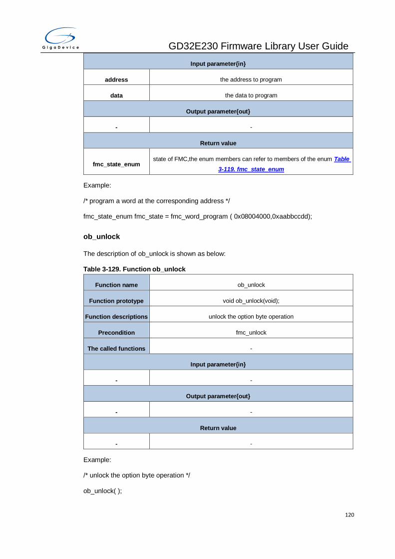
GD32E230 Firmware Library User Guide
120
Input parameter{in}
address the address to program
data the data to program
Output parameter{out}
- -
Return value
fmc_state_enum state of FMC,the enum members can refer to members of the enum Table
3-119. fmc_state_enum
Example:
/* program a word at the corresponding address */
fmc_state_enum fmc_state = fmc_word_program ( 0x08004000,0xaabbccdd);
ob_unlock
The description of ob_unlock is shown as below:
Table 3-129. Function ob_unlock
Function name ob_unlock
Function prototype void ob_unlock(void);
Function descriptions unlock the option byte operation
Precondition fmc_unlock
The called functions -
Input parameter{in}
- -
Output parameter{out}
- -
Return value
- -
Example:
/* unlock the option byte operation */
ob_unlock( );

GD32E230 Firmware Library User Guide
121
ob_lock
The description of ob_lock is shown as below:
Table 3-130. Function ob_lock
Function name ob_lock
Function prototype void ob_lock(void);
Function descriptions lock the option byte operation
Precondition fmc_lock
The called functions -
Input parameter{in}
- -
Output parameter{out}
- -
Return value
- -
Example:
/* lock the option byte operation */
ob_lock( );
ob_reset
The description of ob_reset is shown as below:
Table 3-131. Function ob_reset
Function name ob_reset
Function prototype void ob_reset (void);
Function descriptions reload the option byte and generate a system reset
Precondition -
The called functions -
Input parameter{in}
- -
Output parameter{out}
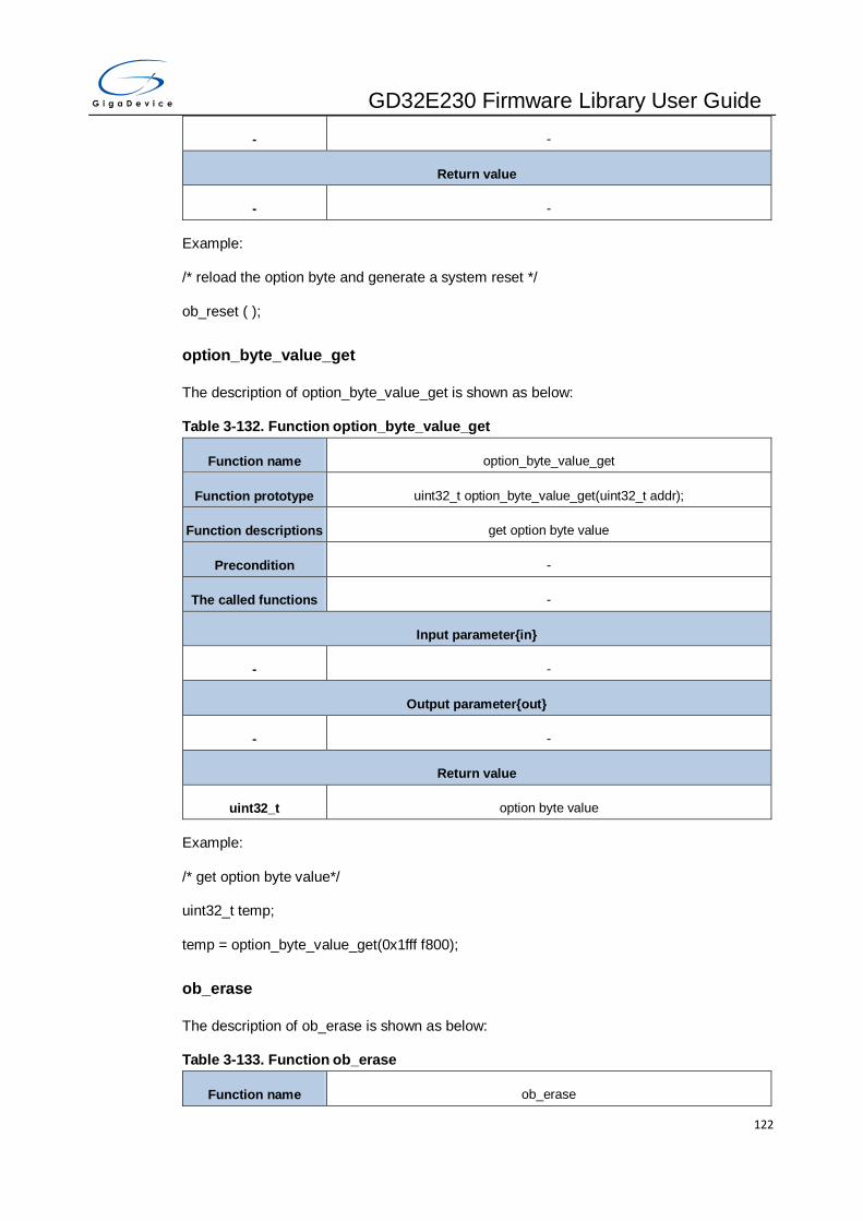
GD32E230 Firmware Library User Guide
122
- -
Return value
- -
Example:
/* reload the option byte and generate a system reset */
ob_reset ( );
option_byte_value_get
The description of option_byte_value_get is shown as below:
Table 3-132. Function option_byte_value_get
Function name option_byte_value_get
Function prototype uint32_t option_byte_value_get(uint32_t addr);
Function descriptions get option byte value
Precondition -
The called functions -
Input parameter{in}
- -
Output parameter{out}
- -
Return value
uint32_t option byte value
Example:
/* get option byte value*/
uint32_t temp;
temp = option_byte_value_get(0x1fff f800);
ob_erase
The description of ob_erase is shown as below:
Table 3-133. Function ob_erase
Function name ob_erase
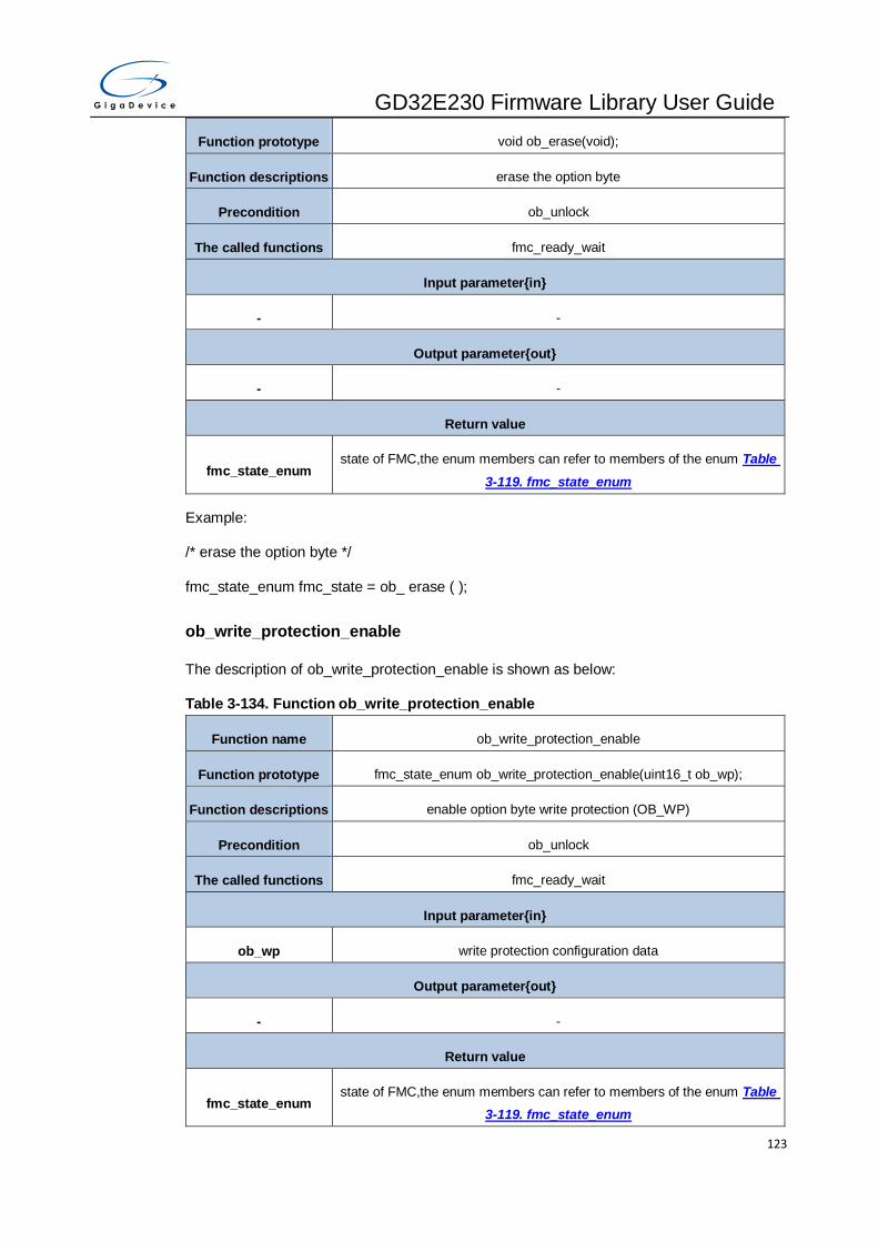
GD32E230 Firmware Library User Guide
123
Function prototype void ob_erase(void);
Function descriptions erase the option byte
Precondition ob_unlock
The called functions fmc_ready_wait
Input parameter{in}
- -
Output parameter{out}
- -
Return value
fmc_state_enum state of FMC,the enum members can refer to members of the enum Table
3-119. fmc_state_enum
Example:
/* erase the option byte */
fmc_state_enum fmc_state = ob_ erase ( );
ob_write_protection_enable
The description of ob_write_protection_enable is shown as below:
Table 3-134. Function ob_write_protection_enable
Function name ob_write_protection_enable
Function prototype fmc_state_enum ob_write_protection_enable(uint16_t ob_wp);
Function descriptions enable option byte write protection (OB_WP)
Precondition ob_unlock
The called functions fmc_ready_wait
Input parameter{in}
ob_wp write protection configuration data
Output parameter{out}
- -
Return value
fmc_state_enum state of FMC,the enum members can refer to members of the enum Table
3-119. fmc_state_enum

GD32E230 Firmware Library User Guide
124
Example:
/* enable write protection */
fmc_state_enum fmc_state = ob_write_protection_enable (0x01);
ob_security_protection_config
The description of ob_security_protection_config is shown as below:
Table 3-135. Function ob_security_protection_config
Function name ob_security_protection_config
Function prototype fmc_state_enum ob_security_protection_config (uint16_t ob_spc);
Function descriptions configure security protection
Precondition ob_unlock
The called functions fmc_ready_wait
Input parameter{in}
ob_spc specify security protection
FMC_NSPC no security protection
FMC_LSPC low security protection
FMC_HSPC high security protection
Output parameter{out}
- -
Return value
fmc_state_enum state of FMC,the enum members can refer to members of the enum Table
3-119. fmc_state_enum
Example:
/* enable security protection */
fmc_state_enum fmc_state;
fmc_state = ob_security_protection_config (FMC_USPC);
ob_user_write
The description of ob_user_write is shown as below:

GD32E230 Firmware Library User Guide
125
Table 3-136. Function ob_user_write
Function name ob_user_write
Function prototype fmc_state_enum ob_user_write(uint8_t ob_user);
Function descriptions program the FMC user option byte
Precondition ob_unlock
The called functions fmc_ready_wait
Input parameter{in}
ob_user user option byte
OB_FWDGT_HW hardware free watchdog timer
OB_DEEPSLEEP_RST no reset when entering deepsleep mode
OB_STDBY_RST no reset when entering deepsleep mode
OB_BOOT1_SET_1 BOOT1 bit is 1
OB_VDDA_DISABLE disable VDDA monitor
OB_SRAM_PARITY_E
NABLE enable SRAM parity check
Output parameter{out}
- -
Return value
fmc_state_enum state of FMC,the enum members can refer to members of the enum Table
3-119. fmc_state_enum
Example:
/* program the FMC user option byte */
fmc_state_enum fmc_state = ob_user_write(OB_FWDGT_HW);
ob_data_program
The description of ob_data_program is shown as below:
Table 3-137. Function ob_data_program
Function name ob_data_program
Function prototype fmc_state_enum ob_data_program(uint16_t data);
Function descriptions program the FMC data option byte

GD32E230 Firmware Library User Guide
126
Precondition ob_unlock
The called functions fmc_ready_wait
Input parameter{in}
data the data to be programmed, OB_DATA[0:15]
Output parameter{out}
- -
Return value
fmc_state_enum state of FMC,the enum members can refer to members of the enum Table
3-119. fmc_state_enum
Example:
/* program option bytes data */
fmc_state_enum fmc_state = ob_data_program (0x56);
ob_user_get
The description of ob_user_get is shown as below:
Table 3-138. Function ob_user_get
Function name ob_user_get
Function prototype uint8_t ob_user_get(void);
Function descriptions get OB_USER in register FMC_OBSTAT
Precondition -
The called functions -
Input parameter{in}
- -
Output parameter{out}
- -
Return value
uint8_t the FMC user option byte values(0x00 – 0xFF)
Example:
/* get the FMC user option byte */
uint8_t user = ob_user_get ( );

GD32E230 Firmware Library User Guide
127
ob_data_get
The description of ob_data_get is shown as below:
Table 3-139. Function ob_data_get
Function name ob_data_get
Function prototype uint16_t ob_data_get(void);
Function descriptions get OB_DATA in register FMC_OBSTAT
Precondition -
The called functions -
Input parameter{in}
- -
Output parameter{out}
- -
Return value
uint16_t the FMC data option byte values(0x0 – 0xFFFF)
Example:
/* get the FMC data option byte */
uint16_t data = ob_data_get ( );
ob_write_protection_get
The description of ob_ write_protection_get is shown as below:
Table 3-140. Function ob_write_protection_get
Function name ob_ write_protection_get
Function prototype uint16_t ob_write_protection_get(void);
Function descriptions get the FMC option byte write protection (OB_WP) in register FMC_WP
Precondition -
The called functions -
Input parameter{in}
- -
Output parameter{out}
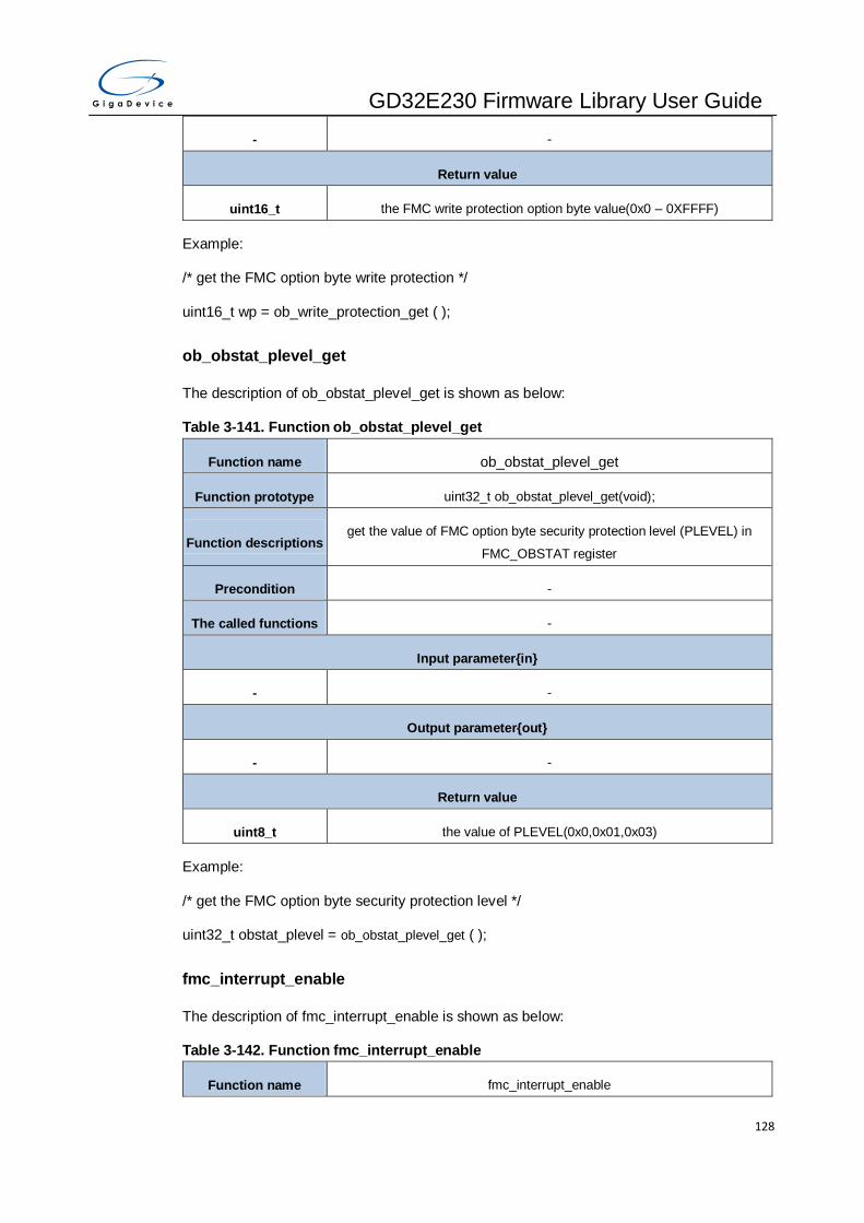
GD32E230 Firmware Library User Guide
128
- -
Return value
uint16_t the FMC write protection option byte value(0x0 – 0XFFFF)
Example:
/* get the FMC option byte write protection */
uint16_t wp = ob_write_protection_get ( );
ob_obstat_plevel_get
The description of ob_obstat_plevel_get is shown as below:
Table 3-141. Function ob_obstat_plevel_get
Function name ob_obstat_plevel_get
Function prototype uint32_t ob_obstat_plevel_get(void);
Function descriptions get the value of FMC option byte security protection level (PLEVEL) in
FMC_OBSTAT register
Precondition -
The called functions -
Input parameter{in}
- -
Output parameter{out}
- -
Return value
uint8_t the value of PLEVEL(0x0,0x01,0x03)
Example:
/* get the FMC option byte security protection level */
uint32_t obstat_plevel = ob_obstat_plevel_get ( );
fmc_interrupt_enable
The description of fmc_interrupt_enable is shown as below:
Table 3-142. Function fmc_interrupt_enable
Function name fmc_interrupt_enable

GD32E230 Firmware Library User Guide
129
Function prototype void fmc_interrupt_enable(uint32_t interrupt);
Function descriptions enable FMC interrupt
Precondition -
The called functions -
Input parameter{in}
interrupt the FMC interrupt source
FMC_INT_END FMC end of program interrupt
FMC_INT_ERR FMC error interrupt
Output parameter{out}
- -
Return value
- -
Example:
/* enable FMC interrupt */
fmc_interrupt_enable(FMC_INT_END);
fmc_interrupt_disable
The description of fmc_interrupt_disable is shown as below:
Table 3-143. Function fmc_interrupt_disable
Function name fmc_interrupt_disable
Function prototype void fmc_interrupt_disable(uint32_t interrupt);
Function descriptions disable FMC interrupt
Precondition -
The called functions -
Input parameter{in}
interrupt the FMC interrupt source
FMC_INT_END FMC end of program interrupt
FMC_INT_ERR FMC error interrupt
Output parameter{out}

GD32E230 Firmware Library User Guide
130
- -
Return value
- -
Example:
/* disable FMC interrupt */
fmc_interrupt_disable(FMC_INT_END);
fmc_flag_get
The description of fmc_flag_get is shown as below:
Table 3-144. Function fmc_flag_get
Function name fmc_flag_get
Function prototype FlagStatus fmc_flag_get(uint32_t flag);
Function descriptions check FMC flag
Precondition -
The called functions -
Input parameter{in}
flag check FMC flag
FMC_FLAG_BUSY FMC busy flag bit
FMC_FLAG_PGERR FMC programming error flag
FMC_FLAG_PGAERR FMC program alignment error flag bit
FMC_FLAG_WPERR FMC write protection error flag
FMC_FLAG_END FMC end of programming flag
Output parameter{out}
- -
Return value
FlagStatus SET or RESET
Example:
/* get FMC flag */
FlagStatus flag = fmc_flag_get(FMC_FLAG_END);

GD32E230 Firmware Library User Guide
131
fmc_flag_clear
The description of fmc_flag_clear is shown as below:
Table 3-145. Function fmc_flag_clear
Function name fmc_flag_clear
Function prototype void fmc_flag_clear(uint32_t flag);
Function descriptions clear the FMC flag by writing 1
Precondition -
The called functions -
Input parameter{in}
flag clear FMC flag
FMC_FLAG_PGERR FMC operation error flag
FMC_FLAG_PGAERR FMC program alignment error flag
FMC_FLAG_WPERR FMC erase/program protection error flag
FMC_FLAG_END FMC end of operation flag
Output parameter{out}
- -
Return value
- -
Example:
/* get FMC flag */
fmc_flag_clear(FMC_FLAG_END);
fmc_interrupt_flag_get
The description of fmc_interrupt_flag_get is shown as below:
Table 3-146. Function fmc_interrupt_flag_get
Function name fmc_interrupt_flag_get
Function prototype FlagStatus fmc_interrupt_flag_get(uint32_t int_flag);
Function descriptions get intrrupt flag set or reset
Precondition -

GD32E230 Firmware Library User Guide
132
The called functions -
Input parameter{in}
flag FMC flag
FMC_INT_FLAG_PGE
RR FMC operation error flag
FMC_INT_FLAG_PGA
ERR FMC program alignment error flag
FMC_INT_FLAG_WPE
RR FMC erase/program protection error flag
FMC_INT_FLAG_END FMC end of operation flag
Output parameter{out}
- -
Return value
FlagStatus SET or RESET
Example:
/* get FMC flag */
FlagStatus flag = fmc_interrupt_flag_get (FMC_INT_FLAG_PGERR);
fmc_interrupt_flag_clear
The description of fmc_interrupt_flag_get is shown as below:
Table 3-147. Function fmc_interrupt_flag_clear
Function name fmc_interrupt_flag_ clear
Function prototype void fmc_interrupt_flag_clear(uint32_t int_flag);
Function descriptions clear the FMC interrupt pending flag by writing 1
Precondition -
The called functions -
Input parameter{in}
flag clear FMC flag
FMC_INT_FLAG_PGE
RR FMC operation error flag

GD32E230 Firmware Library User Guide
133
FMC_INT_FLAG_PGA
ERR FMC program alignment error flag
FMC_INT_FLAG_WPE
RR FMC erase/program protection error flag
FMC_INT_FLAG_END FMC end of operation flag
Output parameter{out}
- -
Return value
- -
Example:
/* clear FMC flag */
fmc_interrupt_flag_get (FMC_INT_FLAG_PGERR);
fmc_state_get
The description of fmc_state_get is shown as below:
Table 3-148. Function fmc_state_get
Function name fmc_state_get
Function prototype fmc_state_enum fmc_state_get(void);
Function descriptions get the FMC state
Precondition -
The called functions -
Input parameter{in}
- -
Output parameter{out}
- -
Return value
fmc_state_enum state of FMC,the enum members can refer to members of the enum Table
3-119. fmc_state_enum
Example:
/* get the FMC state */

GD32E230 Firmware Library User Guide
134
fmc_state_enum state = fmc_state_get( );
fmc_ready_wait
The description of fmc_ready_waitis shown as below:
Table 3-149. Function fmc_ready_wait
Function name fmc_ready_wait
Function prototype fmc_state_enum fmc_ready_wait(uint32_t timeout);
Function descriptions check whether FMC is ready or not
Precondition -
The called functions fmc_state_get()
Input parameter{in}
timeout timeout count
Output parameter{out}
- -
Return value
fmc_state_enum state of FMC,the enum members can refer to members of the enum Table
3-119. fmc_state_enum
Example:
/* check whether FMC is ready or not */
fmc_state_enum state = fmc_ready_wait (0x00001000 );
3.9. FWDGT
The free watchdog timer (FWDGT) is a hardware timing circuitry that can be used to detect
system failures due to software malfunctions. It’s suitable for the situation that requires an
independent environment and lower timing accuracy.The FWDGT registers are listed in
chapter 3.9.1 the FWDGT firmware functions are introduced in chapter 3.9.2.
3.9.1. Descriptions of Peripheral registers
FWDGT registers are listed in the table shown as below:

GD32E230 Firmware Library User Guide
135
Table 3-150. FWDGT Registers
Registers Descriptions
FWDGT_CTL Control register
FWDGT_PSC Prescaler register
FWDGT_RLD Reload register
FWDGT_STAT Status register
FWDGT_WND window register
3.9.2. Descriptions of Peripheral functions
FWDGT firmware functions are listed in the table shown as below:
Table 3-151. FWDGT firmware function
Function name Function description
fwdgt_write_enable enable write access to FWDGT_PSC and FWDGT_RLD
fwdgt_write_disable disable write access to FWDGT_PSC and FWDGT_RLD
fwdgt_enable start the FWDGT counter
fwdgt_prescaler_value_config configure the FWDGT counter clock prescaler value
fwdgt_reload_value_config configure the FWDGT counter reload value
fwdgt_window_value_config configure the FWDGT counter window value
fwdgt_counter_reload reload the counter of FWDGT
fwdgt_config configure counter reload value, and prescaler divider value
fwdgt_flag_get get flag state of FWDGT
fwdgt_write_enable
The description of fwdgt_write_enable is shown as below:
Table 3-152. Function fwdgt_write_ensable
Function name fwdgt_write_enable
Function prototype void fwdgt_write_enable(void);
Function descriptions enable write access to FWDGT_PSC and FWDGT_RLD
Precondition -
The called functions -

GD32E230 Firmware Library User Guide
136
Input parameter{in}
- -
Output parameter{out}
- -
Return value
- -
Example:
/* enable write access to FWDGT_PSC and FWDGT_RLD */
fwdgt_write_enable ( );
fwdgt_write_disable
The description of fwdgt_write_disable is shown as below:
Table 3-153. Function fwdgt_write_disable
Function name fwdgt_write_disable
Function prototype void fwdgt_write_disable(void);
Function descriptions disable write access to FWDGT_PSC and FWDGT_RLD
Precondition -
The called functions -
Input parameter{in}
- -
Output parameter{out}
- -
Return value
- -
Example:
/* disable write access to FWDGT_PSC and FWDGT_RLD */
fwdgt_write_disable ( );
fwdgt_enable
The description of fwdgt_enable is shown as below:

GD32E230 Firmware Library User Guide
137
Table 3-154. Function fwdgt_enable
Function name fwdgt_enable
Function prototype void fwdgt_enable(void);
Function descriptions start the FWDGT counter
Precondition -
The called functions -
Input parameter{in}
- -
Output parameter{out}
- -
Return value
- -
Example:
/* start the free watchdog timer counter */
fwdgt_enable ( );
fwdgt_prescaler_value_config
The description of fwdgt_prescaler_value_config is shown as below:
Table 3-155. Function fwdgt_prescaler_value_config
Function name fwdgt_prescaler_value_config
Function prototype ErrStatus fwdgt_prescaler_value_config(uint16_t prescaler_value);
Function descriptions configure the FWDGT counter clock prescaler value
Precondition -
The called functions -
Input parameter{in}
prescaler_value specify prescaler value
FWDGT_PSC_DIVx FWDGT prescaler set to x(x=4,8,16,32,64,128,256)
Output parameter{out}
- -
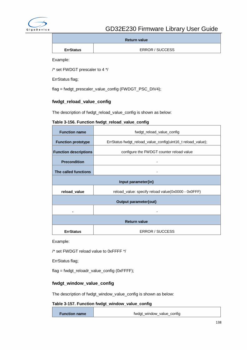
GD32E230 Firmware Library User Guide
138
Return value
ErrStatus ERROR / SUCCESS
Example:
/* set FWDGT prescaler to 4 */
ErrStatus flag;
flag = fwdgt_prescaler_value_config (FWDGT_PSC_DIV4);
fwdgt_reload_value_config
The description of fwdgt_reload_value_config is shown as below:
Table 3-156. Function fwdgt_reload_value_config
Function name fwdgt_reload_value_config
Function prototype ErrStatus fwdgt_reload_value_config(uint16_t reload_value);
Function descriptions configure the FWDGT counter reload value
Precondition -
The called functions -
Input parameter{in}
reload_value reload_value: specify reload value(0x0000 - 0x0FFF)
Output parameter{out}
- -
Return value
ErrStatus ERROR / SUCCESS
Example:
/* set FWDGT reload value to 0xFFFF */
ErrStatus flag;
flag = fwdgt_reloadr_value_config (0xFFFF);
fwdgt_window_value_config
The description of fwdgt_window_value_config is shown as below:
Table 3-157. Function fwdgt_window_value_config
Function name fwdgt_window_value_config

GD32E230 Firmware Library User Guide
139
Function prototype ErrStatus fwdgt_window_value_config(uint16_t window_value);
Function descriptions configure the FWDGT counter window value
Precondition -
The called functions -
Input parameter{in}
window_value window_value: specify window value(0x0000 - 0x0FFF)
Output parameter{out}
- -
Return value
ErrStatus ERROR / SUCCESS
Example:
/* set FWDGT window value to 0xFFFF */
ErrStatus flag;
flag = fwdgt_window_value_config (0xFFFF);
fwdgt_counter_reload
The description of fwdgt_counter_reload is shown as below:
Table 3-158. Function fwdgt_counter_reload
Function name fwdgt_counter_reload
Function prototype void fwdgt_counter_reload(void);
Function descriptions reload the counter of FWDGT
Precondition -
The called functions -
Input parameter{in}
- -
Output parameter{out}
- -
Return value
- -
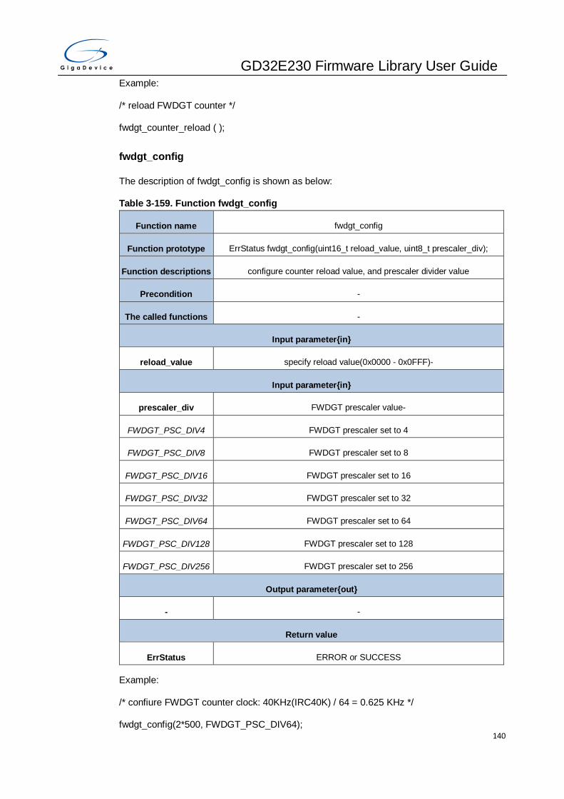
GD32E230 Firmware Library User Guide
140
Example:
/* reload FWDGT counter */
fwdgt_counter_reload ( );
fwdgt_config
The description of fwdgt_config is shown as below:
Table 3-159. Function fwdgt_config
Function name fwdgt_config
Function prototype ErrStatus fwdgt_config(uint16_t reload_value, uint8_t prescaler_div);
Function descriptions configure counter reload value, and prescaler divider value
Precondition -
The called functions -
Input parameter{in}
reload_value specify reload value(0x0000 - 0x0FFF)-
Input parameter{in}
prescaler_div FWDGT prescaler value-
FWDGT_PSC_DIV4 FWDGT prescaler set to 4
FWDGT_PSC_DIV8 FWDGT prescaler set to 8
FWDGT_PSC_DIV16 FWDGT prescaler set to 16
FWDGT_PSC_DIV32 FWDGT prescaler set to 32
FWDGT_PSC_DIV64 FWDGT prescaler set to 64
FWDGT_PSC_DIV128 FWDGT prescaler set to 128
FWDGT_PSC_DIV256 FWDGT prescaler set to 256
Output parameter{out}
- -
Return value
ErrStatus ERROR or SUCCESS
Example:
/* confiure FWDGT counter clock: 40KHz(IRC40K) / 64 = 0.625 KHz */
fwdgt_config(2*500, FWDGT_PSC_DIV64);
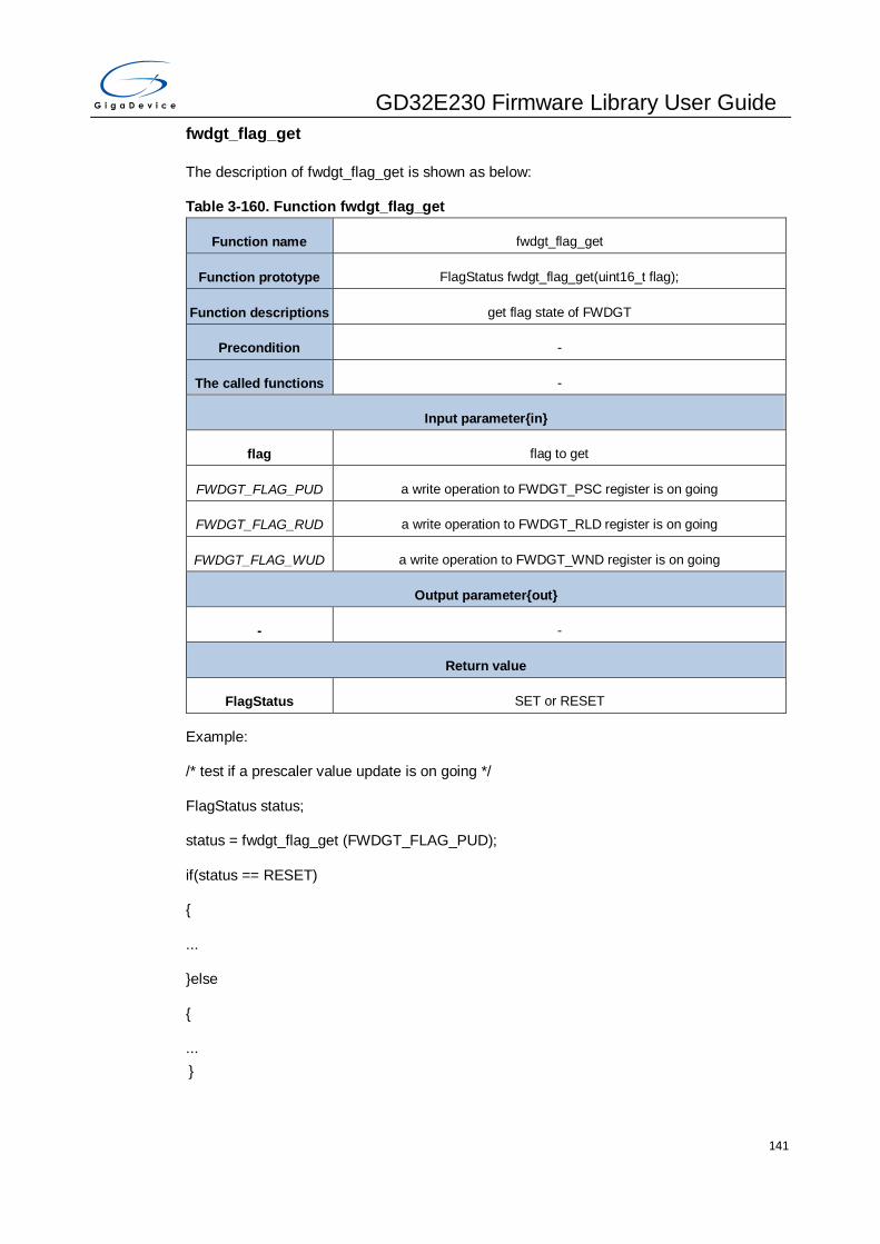
GD32E230 Firmware Library User Guide
141
fwdgt_flag_get
The description of fwdgt_flag_get is shown as below:
Table 3-160. Function fwdgt_flag_get
Function name fwdgt_flag_get
Function prototype FlagStatus fwdgt_flag_get(uint16_t flag);
Function descriptions get flag state of FWDGT
Precondition -
The called functions -
Input parameter{in}
flag flag to get
FWDGT_FLAG_PUD a write operation to FWDGT_PSC register is on going
FWDGT_FLAG_RUD a write operation to FWDGT_RLD register is on going
FWDGT_FLAG_WUD a write operation to FWDGT_WND register is on going
Output parameter{out}
- -
Return value
FlagStatus SET or RESET
Example:
/* test if a prescaler value update is on going */
FlagStatus status;
status = fwdgt_flag_get (FWDGT_FLAG_PUD);
if(status == RESET)
{
...
}else
{
...
}

GD32E230 Firmware Library User Guide
142
3.10. GPIO
GPIO is used to implement logic input/output functions for the devices. The GPIO registers
are listed in chapter 3.10.1, the GPIO firmware functions are introduced in chapter 3.10.2.
3.10.1. Descriptions of Peripheral registers
GPIO registers are listed in the table shown as below:
Table 3-161. GPIO Registers
Registers Descriptions
GPIOx_CTL GPIO port control register
GPIOx_OMODE GPIO port output mode register
GPIOx_OSPD0 GPIO port output speed register 0
GPIOx_PUD GPIO port pull-up/pull-down register
GPIOx_ISTAT GPIO port input status register
GPIOx_OCTL GPIO port output control register
GPIOx_BOP GPIO port bit operation register
GPIOx_LOCK GPIO port configuration lock register
AFIO_AFSEL0 GPIO alternate function selected register 0
AFIO_AFSEL1 GPIO alternate function selected register 1
AFIO_BC GPIO bit clear register
AFIO_TG GPIO port bit toggle register
3.10.2. Descriptions of Peripheral functions
GPIO firmware functions are listed in the table shown as below:
Table 3-162. GPIO firmware function
Function name Function description
gpio_deinit reset GPIO port
gpio_mode_set set GPIO mode
gpio_output_options_set set GPIO output type and speed
gpio_bit_set set GPIO pin bit

GD32E230 Firmware Library User Guide
143
Function name Function description
gpio_bit_reset reset GPIO pin bit
gpio_bit_write write data to the specified GPIO pin
gpio_port_write write data to the specified GPIO port
gpio_input_bit_get get GPIO pin input status
gpio_input_port_get get GPIO port input status
gpio_output_bit_get get GPIO pin output status
gpio_output_port_get get GPIO port output status
gpio_af_set set GPIO alternate function
gpio_pin_lock lock GPIO pin
gpio_bit_toggle toggle GPIO pin status
gpio_port_toggle toggle GPIO port status
gpio_deinit
The description of gpio_deinit is shown as below:
Table 3-163. Function gpio_deinit
Function name gpio_deinit
Function prototype void gpio_deinit(uint32_t gpio_periph);
Function descriptions reset GPIO port
Precondition -
The called functions rcu_periph_reset_enable / rcu_periph_reset_disable
Input parameter{in}
gpio_periph GPIO port
GPIOx GPIOx(x = A,B,C, F)
Output parameter{out}
- -
Return value
- -
Example:

GD32E230 Firmware Library User Guide
144
/* reset GPIOA */
gpio_deinit (GPIOA);
gpio_mode_set
The description of gpio_mode_set is shown as below:
Table 3-164. Function gpio_mode_set
Function name gpio_mode_set
Function prototype void gpio_mode_set(uint32_t gpio_periph, uint32_t mode, uint32_t
pull_up_down, uint32_t pin);
Function descriptions set GPIO mode
Precondition -
The called functions rcu_periph_reset_enable / rcu_periph_reset_disable
Input parameter{in}
gpio_periph GPIO port
GPIOx GPIOx(x = A,B,C,F)
Input parameter{in}
mode gpio pin mode
GPIO_MODE_INPUT input mode
GPIO_MODE_OUTPU
T output mode
GPIO_MODE_AF alternate function mode
GPIO_MODE_ANALO
G analog mode
Input parameter{in}
pull_up_down gpio pin with pull-up or pull-down resistor
GPIO_PUPD_NONE floating mode, no pull-up and pull-down resistors
GPIO_PUPD_PULLUP with pull-up resistor
GPIO_PUPD_PULLDO
WN with pull-down resistor
Input parameter{in}
pin GPIO pin

GD32E230 Firmware Library User Guide
145
GPIO_PIN_x GPIO_PIN_x(x=0..15)
GPIO_PIN_ALL All pins
Output parameter{out}
- -
Return value
- -
Example:
/* config PA0 as input mode with pullup*/
gpio_mode_set (GPIOA, GPIO_MODE_INPUT, GPIO_PUPD_PULLUP, GPIO_PIN_0);
gpio_output_options_set
The description of gpio_output_options_set is shown as below:
Table 3-165. Function gpio_output_options_set
Function name gpio_output_options_set
Function prototype void gpio_output_options_set(uint32_t gpio_periph, uint8_t otype, uint32_t
speed, uint32_t pin);
Function descriptions set GPIO output type and speed
Precondition -
The called functions -
Input parameter{in}
gpio_periph GPIO port
GPIOx GPIOx(x = A,B,C,F)
Input parameter{in}
otype gpio pin output mode
GPIO_OTYPE_PP push pull mode
GPIO_OTYPE_OD open drain mode
Input parameter{in}
speed gpio pin output max speed
GPIO_OSPEED_2MHZ output max speed 2MHz

GD32E230 Firmware Library User Guide
146
GPIO_OSPEED_10MH
Z output max speed 10MHz
GPIO_OSPEED_50MH
Z output max speed 50MHz
Input parameter{in}
pin GPIO pin
GPIO_PIN_x GPIO_PIN_x(x=0..15)
GPIO_PIN_ALL All pins
Output parameter{out}
- -
Return value
- -
Example:
/* config PA0 as push pull mode */
gpio_output_options_set (GPIOA, GPIO_OTYPE_PP, GPIO_OSPEED_2MHZ, GPIO_PIN_0);
gpio_bit_set
The description of gpio_bit_set is shown as below:
Table 3-166. Function gpio_bit_set
Function name gpio_bit_set
Function prototype void gpio_bit_set(uint32_t gpio_periph,uint32_t pin);
Function descriptions set GPIO pin bit
Precondition -
The called functions -
Input parameter{in}
gpio_periph GPIO port
GPIOx GPIOx(x = A,B,C, F)
Input parameter{in}
pin GPIO pin
GPIO_PIN_x GPIO_PIN_x(x=0..15)

GD32E230 Firmware Library User Guide
147
GPIO_PIN_ALL All pins
Output parameter{out}
- -
Return value
- -
Example:
/* set PA0*/
gpio_bit_set (GPIOA, GPIO_PIN_0);
gpio_bit_reset
The description of gpio_bit_reset is shown as below:
Table 3-167. Function gpio_bit_reset
Function name gpio_bit_reset
Function prototype void gpio_bit_reset(uint32_t gpio_periph,uint32_t pin);
Function descriptions reset GPIO pin
Precondition -
The called functions -
Input parameter{in}
gpio_periph GPIO port
GPIOx GPIOx(x = A,B,C,F)
Input parameter{in}
pin GPIO pin
GPIO_PIN_x GPIO_PIN_x(x=0..15)
GPIO_PIN_ALL All pins
Output parameter{out}
- -
Return value
- -
Example:
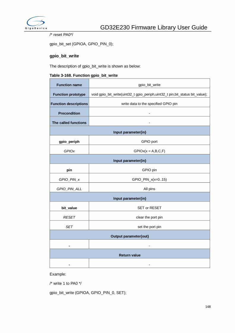
GD32E230 Firmware Library User Guide
148
/* reset PA0*/
gpio_bit_set (GPIOA, GPIO_PIN_0);
gpio_bit_write
The description of gpio_bit_write is shown as below:
Table 3-168. Function gpio_bit_write
Function name gpio_bit_write
Function prototype void gpio_bit_write(uint32_t gpio_periph,uint32_t pin,bit_status bit_value);
Function descriptions write data to the specified GPIO pin
Precondition -
The called functions -
Input parameter{in}
gpio_periph GPIO port
GPIOx GPIOx(x = A,B,C,F)
Input parameter{in}
pin GPIO pin
GPIO_PIN_x GPIO_PIN_x(x=0..15)
GPIO_PIN_ALL All pins
Input parameter{in}
bit_value SET or RESET
RESET clear the port pin
SET set the port pin
Output parameter{out}
- -
Return value
- -
Example:
/* write 1 to PA0 */
gpio_bit_write (GPIOA, GPIO_PIN_0, SET);

GD32E230 Firmware Library User Guide
149
gpio_port_write
The description of gpio_port_write is shown as below:
Table 3-169. Function gpio_port_write
Function name gpio_port_write
Function prototype void gpio_port_write(uint32_t gpio_periph,uint16_t data);
Function descriptions write data to the specified GPIO port
Precondition -
The called functions -
Input parameter{in}
gpio_periph GPIO port
GPIOx GPIOx(x = A,B,C,F)
Input parameter{in}
data specify the value to be written to the port output data register
Output parameter{out}
- -
Return value
- -
Example:
/*write 1010 0101 1010 0101 to Port A */
gpio_port_write (GPIOA, 0xA5A5);
gpio_input_bit_get
The description of gpio_input_bit_get is shown as below:
Table 3-170. Function gpio_input_bit_get
Function name gpio_input_bit_get
Function prototype FlagStatus gpio_input_bit_get(uint32_t gpio_periph,uint32_t pin);
Function descriptions get GPIO pin input status
Precondition -
The called functions -
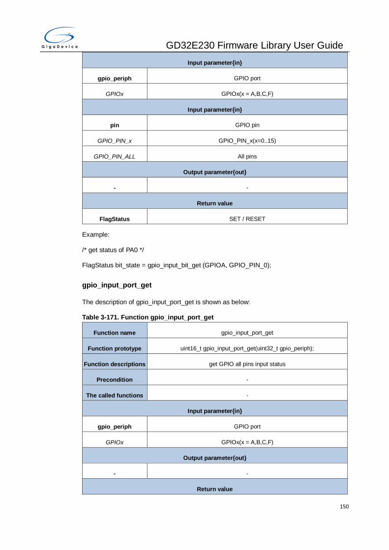
GD32E230 Firmware Library User Guide
150
Input parameter{in}
gpio_periph GPIO port
GPIOx GPIOx(x = A,B,C,F)
Input parameter{in}
pin GPIO pin
GPIO_PIN_x GPIO_PIN_x(x=0..15)
GPIO_PIN_ALL All pins
Output parameter{out}
- -
Return value
FlagStatus SET / RESET
Example:
/* get status of PA0 */
FlagStatus bit_state = gpio_input_bit_get (GPIOA, GPIO_PIN_0);
gpio_input_port_get
The description of gpio_input_port_get is shown as below:
Table 3-171. Function gpio_input_port_get
Function name gpio_input_port_get
Function prototype uint16_t gpio_input_port_get(uint32_t gpio_periph);
Function descriptions get GPIO all pins input status
Precondition -
The called functions -
Input parameter{in}
gpio_periph GPIO port
GPIOx GPIOx(x = A,B,C,F)
Output parameter{out}
- -
Return value

GD32E230 Firmware Library User Guide
151
uint16_t 0x0000-0xFFFF
Example:
/* get input value of Port A */
uint16_t port_state;
port_state = gpio_input_bit_get (GPIOA);
gpio_output_bit_get
The description of gpio_output_bit_get is shown as below:
Table 3-172. Function gpio_output_bit_get
Function name gpio_output_bit_get
Function prototype FlagStatus gpio_output_bit_get(uint32_t gpio_periph,uint32_t pin);
Function descriptions get GPIO pin output status
Precondition -
The called functions -
Input parameter{in}
gpio_periph GPIO port
GPIOx GPIOx(x = A,B,C,F)
Input parameter{in}
pin GPIO pin
GPIO_PIN_x GPIO_PIN_x(x=0..15)
GPIO_PIN_ALL All pins
Output parameter{out}
- -
Return value
FlagStatus SET / RESET
Example:
/* get output status of PA0 */
FlagStatus bit_state;
bit_state = gpio_output_bit_get (GPIOA, GPIO_PIN_0);
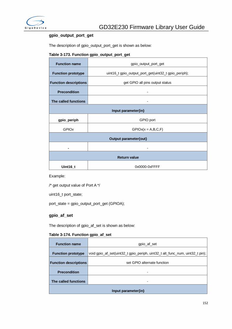
GD32E230 Firmware Library User Guide
152
gpio_output_port_get
The description of gpio_output_port_get is shown as below:
Table 3-173. Function gpio_output_port_get
Function name gpio_output_port_get
Function prototype uint16_t gpio_output_port_get(uint32_t gpio_periph);
Function descriptions get GPIO all pins output status
Precondition -
The called functions -
Input parameter{in}
gpio_periph GPIO port
GPIOx GPIOx(x = A,B,C,F)
Output parameter{out}
- -
Return value
Uint16_t 0x0000-0xFFFF
Example:
/* get output value of Port A */
uint16_t port_state;
port_state = gpio_output_port_get (GPIOA);
gpio_af_set
The description of gpio_af_set is shown as below:
Table 3-174. Function gpio_af_set
Function name gpio_af_set
Function prototype void gpio_af_set(uint32_t gpio_periph, uint32_t alt_func_num, uint32_t pin);
Function descriptions set GPIO alternate function
Precondition -
The called functions -
Input parameter{in}

GD32E230 Firmware Library User Guide
153
gpio_periph GPIO port
GPIOx GPIOx(x = A,B,C)
Input parameter{in}
alt_func_num GPIO pin af function, please refer to specific device datasheet
GPIO_AF_0 TIMER13, TIMER14, TIMER16, SPI0, SPI1, I2S0, CK_OUT, USART0,
I2C0, I2C1, SWDIO, SWCLK
GPIO_AF_1 USART0, USART1, TIMER14, I2C0, I2C1
GPIO_AF_2 TIMER0, TIMER1, TIMER15, TIMER16, I2S0
GPIO_AF_3 I2C0, TIMER14
GPIO_AF_4 (port A,B
only) USART1, I2C0, I2C1, TIMER13
GPIO_AF_5 (port A,B
only) TIMER15, TIMER16, I2S0
GPIO_AF_6 (port A,B
only) SPI1
GPIO_AF_7 (port A,B
only) CMP
Input parameter{in}
pin GPIO pin
GPIO_PIN_x GPIO_PIN_x(x=0..15)
GPIO_PIN_ALL All pins
Output parameter{out}
- -
Return value
- -
Example:
/*set PA0 alternate function 0*/
gpio_af_set(GPIOA, GPIO_AF_0, GPIO_PIN_0);
gpio_pin_lock
The description of gpio_pin_lock is shown as below:

GD32E230 Firmware Library User Guide
154
Table 3-175. Function gpio_pin_lock
Function name gpio_pin_lock
Function prototype void gpio_pin_lock(uint32_t gpio_periph, uint32_t pin);
Function descriptions lock GPIO pin bit
Precondition -
The called functions -
Input parameter{in}
gpio_periph GPIO port
GPIOx GPIOx(x = A,B)
Input parameter{in}
pin GPIO pin
GPIO_PIN_x GPIO_PIN_x(x=0..15)
GPIO_PIN_ALL All pins
Output parameter{out}
- -
Return value
- -
Example:
/* lock PA0*/
gpio_pin_lock (GPIOA, GPIO_PIN_ 0);
gpio_bit_toggle
The description of gpio_bit_toggle is shown as below:
Table 3-176. Function gpio_bit_toggle
Function name gpio_bit_toggle
Function prototype void gpio_bit_toggle(uint32_t gpio_periph, uint32_t pin);
Function descriptions toggle GPIO pin status
Precondition -
The called functions -

GD32E230 Firmware Library User Guide
155
Input parameter{in}
gpio_periph GPIO port
GPIOx GPIOx(x = A,B,C,F)
Input parameter{in}
pin GPIO pin
GPIO_PIN_x GPIO_PIN_x(x=0..15)
GPIO_PIN_ALL GPIO_PIN_ALL
Output parameter{out}
- -
Return value
- -
Example:
/* toggle PA0 */
gpio_bit_toggle (GPIOA, GPIO_ PIN_0);
gpio_port_toggle
The description of gpio_port_toggle is shown as below:
Table 3-177. Function gpio_port_toggle
Function name gpio_port_toggle
Function prototype void gpio_port_toggle(uint32_t gpio_periph);
Function descriptions toggle GPIO port status
Precondition -
The called functions -
Input parameter{in}
gpio_periph GPIO port
GPIOx GPIOx(x = A,B,C,F)
Output parameter{out}
- -
Return value
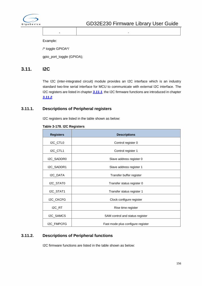
GD32E230 Firmware Library User Guide
156
- -
Example:
/* toggle GPIOA*/
gpio_port_toggle (GPIOA);
3.11. I2C
The I2C (inter-integrated circuit) module provides an I2C interface which is an industry
standard two-line serial interface for MCU to communicate with external I2C interface. The
I2C registers are listed in chapter 3.11.1, the I2C firmware functions are introduced in chapter
3.11.2.
3.11.1. Descriptions of Peripheral registers
I2C registers are listed in the table shown as below:
Table 3-178. I2C Registers
Registers Descriptions
I2C_CTL0 Control register 0
I2C_CTL1 Control register 1
I2C_SADDR0 Slave address register 0
I2C_SADDR1 Slave address register 1
I2C_DATA Transfer buffer register
I2C_STAT0 Transfer status register 0
I2C_STAT1 Transfer status register 1
I2C_CKCFG Clock configure register
I2C_RT Rise time register
I2C_SAMCS SAM control and status register
I2C_FMPCFG Fast mode plus configure register
3.11.2. Descriptions of Peripheral functions
I2C firmware functions are listed in the table shown as below:

GD32E230 Firmware Library User Guide
157
Table 3-179. I2C firmware function
Function name Function description
i2c_deinit reset I2C
i2c_clock_config configure I2C clock
i2c_mode_addr_config configure I2C address
i2c_smbus_type_config SMBus type selection
i2c_ack_config whether or not to send an ACK
i2c_ackpos_config configure I2C ACK position
i2c_master_addressing master send slave address
i2c_dualaddr_enable enable dual-address mode
i2c_dualaddr_disable disable dual-address mode
i2c_enable enable I2C
i2c_disable disable I2C
i2c_start_on_bus generate a START condition on I2C bus
i2c_stop_on_bus generate a STOP condition on I2C bus
i2c_data_transmit I2C transmit data function
i2c_data_receive I2C receive data function
i2c_dma_enable I2C DMA mode enable
i2c_dma_last_transfer_config configure whether next DMA EOT is DMA last transfer or not
i2c_stretch_scl_low_config whether to stretch SCL low when data is not ready in slave
mode
i2c_slave_response_to_gcall_config whether or not to response to a general call
i2c_software_reset_config software reset I2C
i2c_pec_enable whether I2C PEC calculation is enabled
i2c_pec_transfer_enable I2C whether to transfer PEC value
i2c_pec_value_get packet error checking value
i2c_smbus_issue_alert I2C issue alert through SMBA pin
i2c_smbus_arp_enable whether ARP is enabled under SMBus
i2c_sam_enable enable SAM_V interface

GD32E230 Firmware Library User Guide
158
Function name Function description
i2c_sam_disable disable SAM_V interface
i2c_sam_timeout_enable enable SAM_V interface timeout detect
i2c_sam_timeout_disable disable SAM_V interface timeout detect
i2c_flag_get check I2C flag is set or not
i2c_flag_clear clear I2C flag
i2c_interrupt_enable enable I2C interrupt
i2c_interrupt_disable disable I2C interrupt
i2c_interrupt_flag_get check I2C interrupt flag
i2c_interrupt_flag_clear clear I2C interrupt flag
i2c_deinit
The description of i2c_deinit is shown as below:
Table 3-180. Function i2c_deinit
Function name i2c_deinit
Function prototype void i2c_deinit(uint32_t i2c_periph);
Function descriptions reset I2C
Precondition -
The called functions rcu_periph_reset_enable / rcu_periph_reset_disable
Input parameter{in}
i2c_periph I2C peripheral
I2Cx (x=0,1)
Output parameter{out}
- -
Return value
- -
Example:
/* reset I2C0 */
i2c_deinit (I2C0);

GD32E230 Firmware Library User Guide
159
i2c_clock_config
The description of i2c_clock_config is shown as below:
Table 3-181. Function i2c_clock_config
Function name i2c_clock_config
Function prototype void i2c_clock_config(uint32_t i2c_periph, uint32_t clkspeed, uint32_t
dutycyc);
Function descriptions I2C clock configure
Precondition -
The called functions rcu_clock_freq_get
Input parameter{in}
i2c_periph I2C peripheral
I2Cx (x=0,1)
Input parameter{in}
clkspeed i2c clock speed
Input parameter{in}
dutycyc duty cycle in fast mode
I2C_DTCY_2 T_low/T_high=2
I2C_DTCY_16_9 T_low/T_high=16/9
Output parameter{out}
- -
Return value
- -
Example:
/* configure I2C0 clock speed as 100KHz*/
i2c_clock_config(I2C0, 100000, I2C_DTCY_2);
i2c_mode_addr_config
The description of i2c_mode_addr_config is shown as below:
Table 3-182. Function i2c_mode_addr_config
Function name i2c_mode_addr_config

GD32E230 Firmware Library User Guide
160
Function prototype void i2c_mode_addr_config(uint32_t i2c_periph, uint32_t mode, uint32_t
addformat, uint32_t addr);
Function descriptions configure I2C address
Precondition -
The called functions -
Input parameter{in}
i2c_periph I2C peripheral
I2Cx (x=0,1)
Input parameter{in}
mode I2C mode select
I2C_I2CMODE_ENABL
E I2C mode
I2C_SMBUSMODE_EN
ABLE SMBus mode
Input parameter{in}
addformat 7bits or 10bits
I2C_ADDFORMAT_7BI
TS 7bits
I2C_ADDFORMAT_10
BITS 10bits
Input parameter{in}
addr I2C address
Output parameter{out}
- -
Return value
- -
Example:
/* configure I2C0 address as 0x82, using 7 bits */
i2c_mode_addr_config(I2C0, I2C_I2CMODE_ENABLE, I2C_ADDFORMAT_7BITS, 0x82);

GD32E230 Firmware Library User Guide
161
i2c_smbus_type_config
The description of i2c_smbus_type_config is shown as below:
Table 3-183. Function i2c_smbus_type_config
Function name i2c_smbus_type_config
Function prototype void i2c_smbus_type_config(uint32_t i2c_periph, uint32_t type);
Function descriptions SMBus type selection
Precondition -
The called functions -
Input parameter{in}
i2c_periph I2C peripheral
I2Cx (x=0,1)
Input parameter{in}
type Device or host
I2C_SMBUS_DEVICE device
I2C_SMBUS_HOST host
Output parameter{out}
- -
Return value
- -
Example:
/* config I2C0 as SMBUS host type*/
i2c_smbus_type_config (I2C0, I2C_SMBUS_HOST);
i2c_ack_config
The description of i2c_ack_config is shown as below:
Table 3-184. Function i2c_ack_config
Function name i2c_ack_config
Function prototype void i2c_ack_config(uint32_t i2c_periph, uint32_t ack);
Function descriptions whether or not to send an ACK

GD32E230 Firmware Library User Guide
162
Precondition -
The called functions -
Input parameter{in}
i2c_periph I2C peripheral
I2Cx (x=0,1)
Input parameter{in}
ack whether or not to send an ACK
I2C_ACK_ENABLE ACK will be sent
I2C_ACK_DISABLE ACK will not be sent
Output parameter{out}
- -
Return value
- -
Example:
/* I2C0 will send ACK */
i2c_ack_config (I2C0, I2C_ACK_ENABLE);
i2c_ackpos_config
The description of i2c_ackpos_config is shown as below:
Table 3-185. Function i2c_ackpos_config
Function name i2c_ackpos_config
Function prototype void i2c_ackpos_config(uint32_t i2c_periph, uint32_t pos);
Function descriptions I2C POAP position configure
Precondition -
The called functions -
Input parameter{in}
i2c_periph I2C peripheral
I2Cx (x=0,1)
Input parameter{in}

GD32E230 Firmware Library User Guide
163
pos ACK position
I2C_ACKPOS_CURRE
NT whether to send ACK or not for the current
I2C_ACKPOS_NEXT whether to send ACK or not for the next byte
Output parameter{out}
- -
Return value
- -
Example:
/* The ACK of I2C0 is send for the current frame*/
i2c_ackpos_config (I2C0, I2C_ACKPOS_CURRENT);
i2c_master_addressing
The description of i2c_master_addressing is shown as below:
Table 3-186. Function i2c_master_addressing
Function name i2c_master_addressing
Function prototype void i2c_master_addressing(uint32_t i2c_periph, uint32_t addr, uint32_t
trandirection);
Function descriptions master sends slave address
Precondition -
The called functions -
Input parameter{in}
i2c_periph I2C peripheral
I2Cx (x=0,1)
Input parameter{in}
addr slave address
Input parameter{in}
trandirection transmitter or receiver
I2C_TRANSMITTER transmitter
I2C_RECEIVER receiver

GD32E230 Firmware Library User Guide
164
Output parameter{out}
- -
Return value
- -
Example:
/* send slave address to I2C bus and I2C0 act as receiver */
i2c_master_addressing(I2C0, 0x82, I2C_RECEIVER);
i2c_dualaddr_enable
The description of i2c_dualaddr_enable is shown as below:
Table 3-187. Function i2c_dualaddr_enable
Function name i2c_dualaddr_enable
Function prototype void i2c_dualaddr_enable(uint32_t i2c_periph, uint32_t addr)
Function descriptions dual-address mode enable
Precondition -
The called functions -
Input parameter{in}
i2c_periph I2C peripheral
I2Cx (x=0,1)
Input parameter{in}
addr second address in dual-address mode
Output parameter{out}
- -
Return value
- -
Example:
/* enable I2C0 dual-address*/
i2c_dualaddr_enable (I2C0, 0x80);

GD32E230 Firmware Library User Guide
165
i2c_dualaddr_disable
The description of i2c_dualaddr_disable is shown as below:
Table 3-188. Function i2c_dualaddr_enable
Function name i2c_dualaddr_disable
Function prototype void i2c_dualaddr_disable(uint32_t i2c_periph)
Function descriptions dual-address mode disable
Precondition -
The called functions -
Input parameter{in}
i2c_periph I2C peripheral
I2Cx (x=0,1)
Output parameter{out}
- -
Return value
- -
Example:
/* disable I2C0 dual-address*/
i2c_dualaddr_disable (I2C0);
i2c_enable
The description of i2c_enable is shown as below:
Table 3-189. Function i2c_enable
Function name i2c_enable
Function prototype void i2c_enable(uint32_t i2c_periph);
Function descriptions enable I2C
Precondition -
The called functions -
Input parameter{in}
i2c_periph I2C peripheral
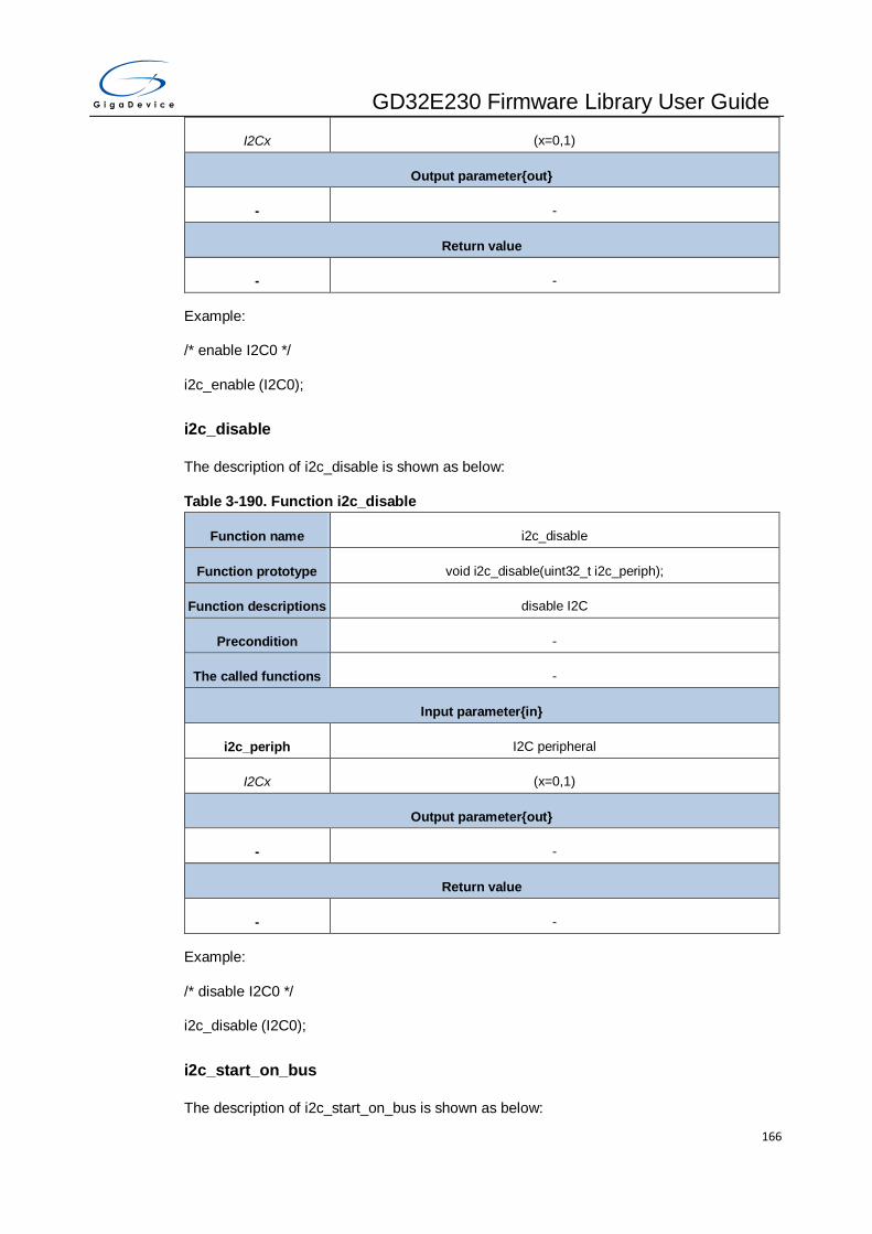
GD32E230 Firmware Library User Guide
166
I2Cx (x=0,1)
Output parameter{out}
- -
Return value
- -
Example:
/* enable I2C0 */
i2c_enable (I2C0);
i2c_disable
The description of i2c_disable is shown as below:
Table 3-190. Function i2c_disable
Function name i2c_disable
Function prototype void i2c_disable(uint32_t i2c_periph);
Function descriptions disable I2C
Precondition -
The called functions -
Input parameter{in}
i2c_periph I2C peripheral
I2Cx (x=0,1)
Output parameter{out}
- -
Return value
- -
Example:
/* disable I2C0 */
i2c_disable (I2C0);
i2c_start_on_bus
The description of i2c_start_on_bus is shown as below:
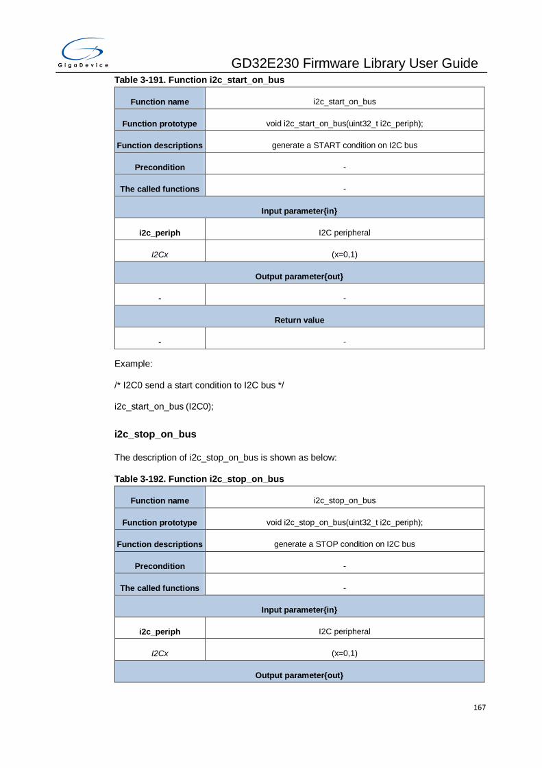
GD32E230 Firmware Library User Guide
167
Table 3-191. Function i2c_start_on_bus
Function name i2c_start_on_bus
Function prototype void i2c_start_on_bus(uint32_t i2c_periph);
Function descriptions generate a START condition on I2C bus
Precondition -
The called functions -
Input parameter{in}
i2c_periph I2C peripheral
I2Cx (x=0,1)
Output parameter{out}
- -
Return value
- -
Example:
/* I2C0 send a start condition to I2C bus */
i2c_start_on_bus (I2C0);
i2c_stop_on_bus
The description of i2c_stop_on_bus is shown as below:
Table 3-192. Function i2c_stop_on_bus
Function name i2c_stop_on_bus
Function prototype void i2c_stop_on_bus(uint32_t i2c_periph);
Function descriptions generate a STOP condition on I2C bus
Precondition -
The called functions -
Input parameter{in}
i2c_periph I2C peripheral
I2Cx (x=0,1)
Output parameter{out}
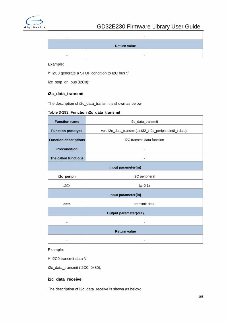
GD32E230 Firmware Library User Guide
168
- -
Return value
- -
Example:
/* I2C0 generate a STOP condition to I2C bus */
i2c_stop_on_bus (I2C0);
i2c_data_transmit
The description of i2c_data_transmit is shown as below:
Table 3-193. Function i2c_data_transmit
Function name i2c_data_transmit
Function prototype void i2c_data_transmit(uint32_t i2c_periph, uint8_t data);
Function descriptions I2C transmit data function
Precondition -
The called functions -
Input parameter{in}
i2c_periph I2C peripheral
I2Cx (x=0,1)
Input parameter{in}
data transmit data
Output parameter{out}
- -
Return value
- -
Example:
/* I2C0 transmit data */
i2c_data_transmit (I2C0, 0x80);
i2c_data_receive
The description of i2c_data_receive is shown as below:
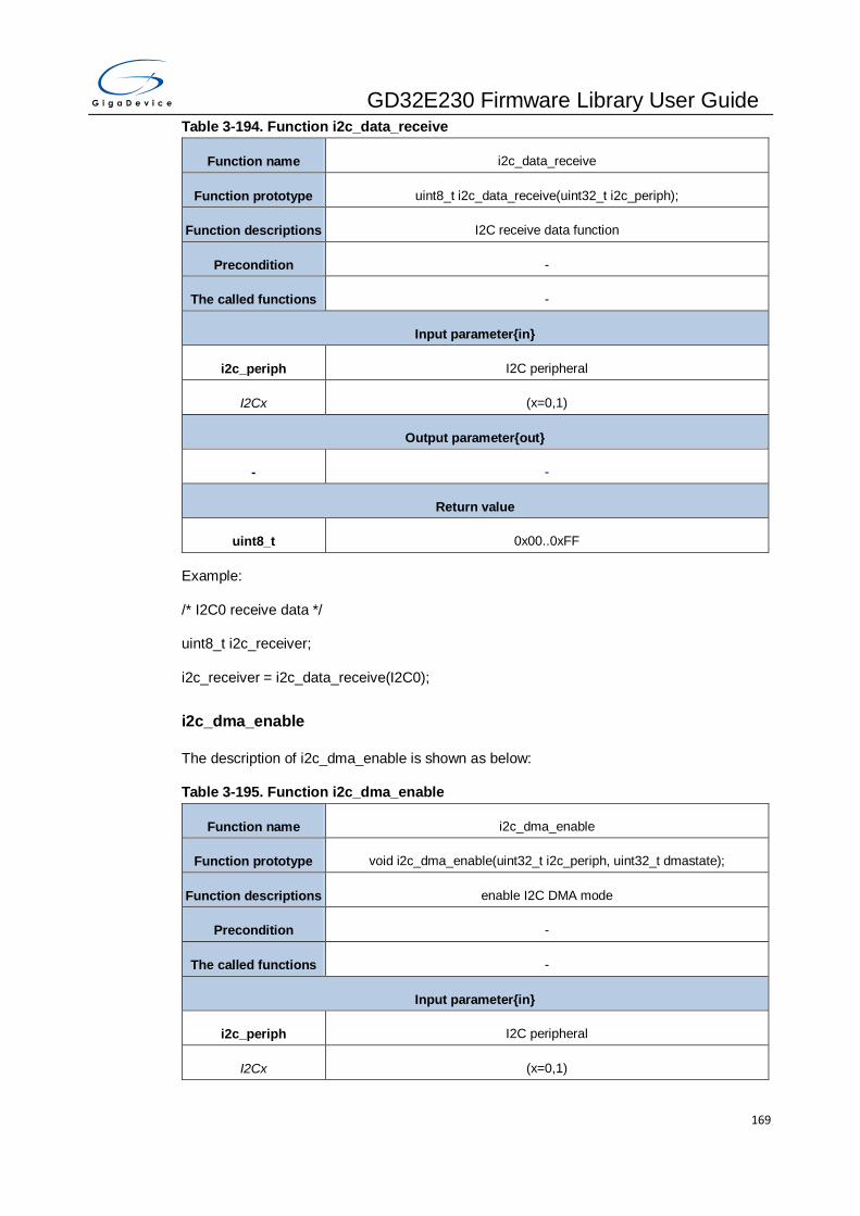
GD32E230 Firmware Library User Guide
169
Table 3-194. Function i2c_data_receive
Function name i2c_data_receive
Function prototype uint8_t i2c_data_receive(uint32_t i2c_periph);
Function descriptions I2C receive data function
Precondition -
The called functions -
Input parameter{in}
i2c_periph I2C peripheral
I2Cx (x=0,1)
Output parameter{out}
- -
Return value
uint8_t 0x00..0xFF
Example:
/* I2C0 receive data */
uint8_t i2c_receiver;
i2c_receiver = i2c_data_receive(I2C0);
i2c_dma_enable
The description of i2c_dma_enable is shown as below:
Table 3-195. Function i2c_dma_enable
Function name i2c_dma_enable
Function prototype void i2c_dma_enable(uint32_t i2c_periph, uint32_t dmastate);
Function descriptions enable I2C DMA mode
Precondition -
The called functions -
Input parameter{in}
i2c_periph I2C peripheral
I2Cx (x=0,1)
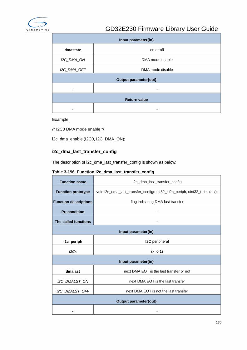
GD32E230 Firmware Library User Guide
170
Input parameter{in}
dmastate on or off
I2C_DMA_ON DMA mode enable
I2C_DMA_OFF DMA mode disable
Output parameter{out}
- -
Return value
- -
Example:
/* I2C0 DMA mode enable */
i2c_dma_enable (I2C0, I2C_DMA_ON);
i2c_dma_last_transfer_config
The description of i2c_dma_last_transfer_config is shown as below:
Table 3-196. Function i2c_dma_last_transfer_config
Function name i2c_dma_last_transfer_config
Function prototype void i2c_dma_last_transfer_config(uint32_t i2c_periph, uint32_t dmalast);
Function descriptions flag indicating DMA last transfer
Precondition -
The called functions -
Input parameter{in}
i2c_periph I2C peripheral
I2Cx (x=0,1)
Input parameter{in}
dmalast next DMA EOT is the last transfer or not
I2C_DMALST_ON next DMA EOT is the last transfer
I2C_DMALST_OFF next DMA EOT is not the last transfer
Output parameter{out}
- -

GD32E230 Firmware Library User Guide
171
Return value
- -
Example:
/* next DMA EOT is the last transfer */
i2c_dma_last_transfer_config (I2C0, I2C_DMALST_ON);
i2c_stretch_scl_low_config
The description of i2c_stretch_scl_low_config is shown as below:
Table 3-197. Function i2c_stretch_scl_low_config
Function name i2c_stretch_scl_low_config
Function prototype void i2c_stretch_scl_low_config(uint32_t i2c_periph, uint32_t stretchpara);
Function descriptions whether to stretch SCL low when data is not ready in slave mode
Precondition -
The called functions -
Input parameter{in}
i2c_periph I2C peripheral
I2Cx (x=0,1)
Input parameter{in}
stretchpara SCL stretching enable or disable
I2C_SCLSTRETCH_EN
ABLE SCL stretching is enabled
I2C_SCLSTRETCH_DI
SABLE SCL stretching is disabled
Output parameter{out}
- -
Return value
- -
Example:
/* stretch SCL low when data is not ready in slave mode */
i2c_stretch_scl_low_config (I2C0, I2C_SCLSTRETCH_ENABLE);

GD32E230 Firmware Library User Guide
172
i2c_slave_response_to_gcall_config
The description of i2c_slave_response_to_gcall_config is shown as below:
Table 3-198. Function i2c_slave_response_to_gcall_config
Function name i2c_slave_response_to_gcall_config
Function prototype void i2c_slave_response_to_gcall_config(uint32_t i2c_periph, uint32_t
gcallpara);
Function descriptions whether or not to response to a general call
Precondition -
The called functions -
Input parameter{in}
i2c_periph I2C peripheral
I2Cx (x=0,1)
Input parameter{in}
gcallpara response to a general call or not
I2C_GCEN_ENABLE slave will response to a general call
I2C_GCEN_DISABLE slave will not response to a general call
Output parameter{out}
- -
Return value
- -
Example:
/* I2C0 will response to a general call */
i2c_slave_response_to_gcall_config (I2C0, I2C_GCEN_ENABLE);
i2c_software_reset_config
The description of i2c_software_reset_config is shown as below:
Table 3-199. Function i2c_software_reset_config
Function name i2c_software_reset_config
Function prototype void i2c_software_reset_config(uint32_t i2c_periph, uint32_t sreset);
Function descriptions software reset I2C
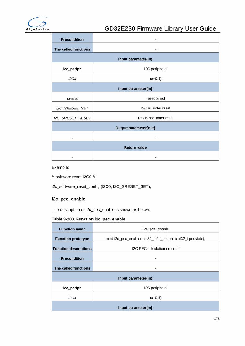
GD32E230 Firmware Library User Guide
173
Precondition -
The called functions -
Input parameter{in}
i2c_periph I2C peripheral
I2Cx (x=0,1)
Input parameter{in}
sreset reset or not
I2C_SRESET_SET I2C is under reset
I2C_SRESET_RESET I2C is not under reset
Output parameter{out}
- -
Return value
- -
Example:
/* software reset I2C0 */
i2c_software_reset_config (I2C0, I2C_SRESET_SET);
i2c_pec_enable
The description of i2c_pec_enable is shown as below:
Table 3-200. Function i2c_pec_enable
Function name i2c_pec_enable
Function prototype void i2c_pec_enable(uint32_t i2c_periph, uint32_t pecstate);
Function descriptions I2C PEC calculation on or off
Precondition -
The called functions -
Input parameter{in}
i2c_periph I2C peripheral
I2Cx (x=0,1)
Input parameter{in}

GD32E230 Firmware Library User Guide
174
pecstate on or off
I2C_PEC_ENABLE PEC calculation on
I2C_PEC_DISABLE PEC calculation off
Output parameter{out}
- -
Return value
- -
Example:
/* Enable I2C PEC calculation */
i2c_pec_enable (I2C0, I2C_PEC_ENABLE);
i2c_pec_transfer_enable
The description of i2c_pec_transfer_enable is shown as below:
Table 3-201. Function i2c_pec_transfer_enable
Function name i2c_pec_transfer_enable
Function prototype void i2c_pec_transfer_enable(uint32_t i2c_periph, uint32_t pecpara);
Function descriptions I2C whether to transfer PEC value
Precondition -
The called functions -
Input parameter{in}
i2c_periph I2C peripheral
I2Cx (x=0,1)
Input parameter{in}
pecpara Transfer PEC or not
I2C_PECTRANS_ENA
BLE transfer PEC
I2C_PECTRANS_DISA
BLE not transfer PEC
Output parameter{out}
- -
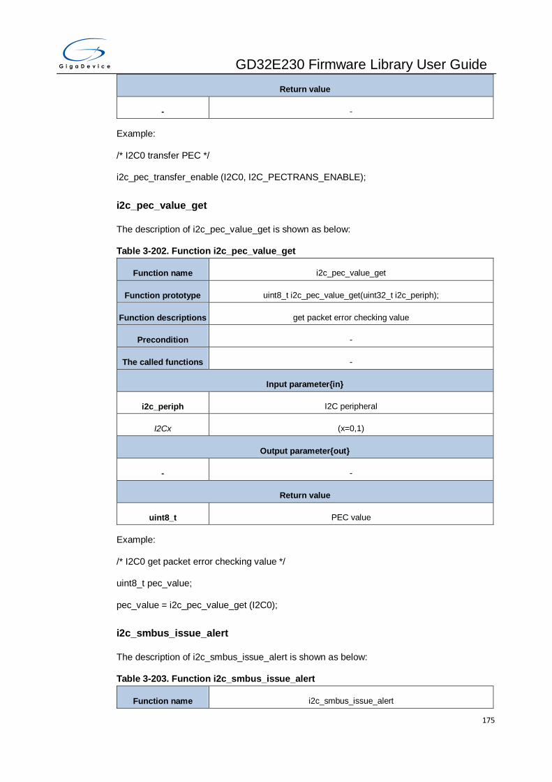
GD32E230 Firmware Library User Guide
175
Return value
- -
Example:
/* I2C0 transfer PEC */
i2c_pec_transfer_enable (I2C0, I2C_PECTRANS_ENABLE);
i2c_pec_value_get
The description of i2c_pec_value_get is shown as below:
Table 3-202. Function i2c_pec_value_get
Function name i2c_pec_value_get
Function prototype uint8_t i2c_pec_value_get(uint32_t i2c_periph);
Function descriptions get packet error checking value
Precondition -
The called functions -
Input parameter{in}
i2c_periph I2C peripheral
I2Cx (x=0,1)
Output parameter{out}
- -
Return value
uint8_t PEC value
Example:
/* I2C0 get packet error checking value */
uint8_t pec_value;
pec_value = i2c_pec_value_get (I2C0);
i2c_smbus_issue_alert
The description of i2c_smbus_issue_alert is shown as below:
Table 3-203. Function i2c_smbus_issue_alert
Function name i2c_smbus_issue_alert

GD32E230 Firmware Library User Guide
176
Function prototype void i2c_smbus_issue_alert(uint32_t i2c_periph, uint32_t smbuspara);
Function descriptions I2C issue alert through SMBA pin
Precondition -
The called functions -
Input parameter{in}
i2c_periph I2C peripheral
I2Cx (x=0,1)
Input parameter{in}
smbuspara issue alert through SMBA pin or not
I2C_SALTSEND_ENAB
LE issue alert through SMBA pin
I2C_SALTSEND_DISA
BLE not issue alert through SMBA pin
Output parameter{out}
- -
Return value
- -
Example:
/* I2C0 issue alert through SMBA pin enable*/
i2c_smbus_issue_alert (I2C0, I2C_SALTSEND_ENABLE);
i2c_smbus_arp_enable
The description of i2c_smbus_arp_enable is shown as below:
Table 3-204. Function i2c_smbus_arp_enable
Function name i2c_smbus_arp_enable
Function prototype void i2c_smbus_arp_enable(uint32_t i2c_periph, uint32_t arpstate);
Function descriptions enable or disable I2C ARP protocol in SMBus switch
Precondition -
The called functions -
Input parameter{in}
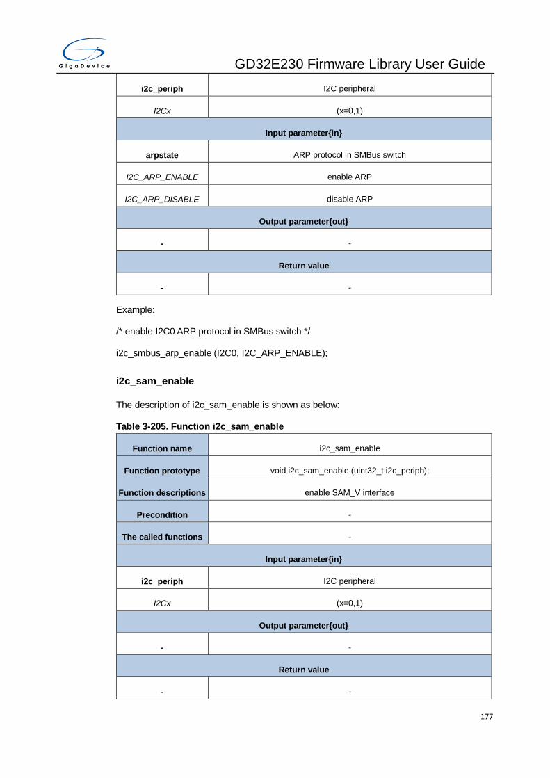
GD32E230 Firmware Library User Guide
177
i2c_periph I2C peripheral
I2Cx (x=0,1)
Input parameter{in}
arpstate ARP protocol in SMBus switch
I2C_ARP_ENABLE enable ARP
I2C_ARP_DISABLE disable ARP
Output parameter{out}
- -
Return value
- -
Example:
/* enable I2C0 ARP protocol in SMBus switch */
i2c_smbus_arp_enable (I2C0, I2C_ARP_ENABLE);
i2c_sam_enable
The description of i2c_sam_enable is shown as below:
Table 3-205. Function i2c_sam_enable
Function name i2c_sam_enable
Function prototype void i2c_sam_enable (uint32_t i2c_periph);
Function descriptions enable SAM_V interface
Precondition -
The called functions -
Input parameter{in}
i2c_periph I2C peripheral
I2Cx (x=0,1)
Output parameter{out}
- -
Return value
- -

GD32E230 Firmware Library User Guide
178
Example:
/* enable I2C0 SAM_V interface */
i2c_sam_enable (I2C0);
i2c_sam_disable
The description of i2c_sam_disable is shown as below:
Table 3-206. Function i2c_sam_disable
Function name i2c_sam_disable
Function prototype void i2c_sam_disable (uint32_t i2c_periph);
Function descriptions disable SAM_V interface
Precondition -
The called functions -
Input parameter{in}
i2c_periph I2C peripheral
I2Cx (x=0,1)
Output parameter{out}
- -
Return value
- -
Example:
/* disable I2C0 SAM_V interface*/
i2c_sam_disable (I2C0);
i2c_sam_timeout_enable
The description of i2c_sam_timeout_enable is shown as below:
Table 3-207. Function i2c_sam_timeout_enable
Function name i2c_sam_timeout_enable
Function prototype void i2c_sam_timeout_enable (uint32_t i2c_periph);
Function descriptions enable SAM_V interface timeout detect
Precondition -
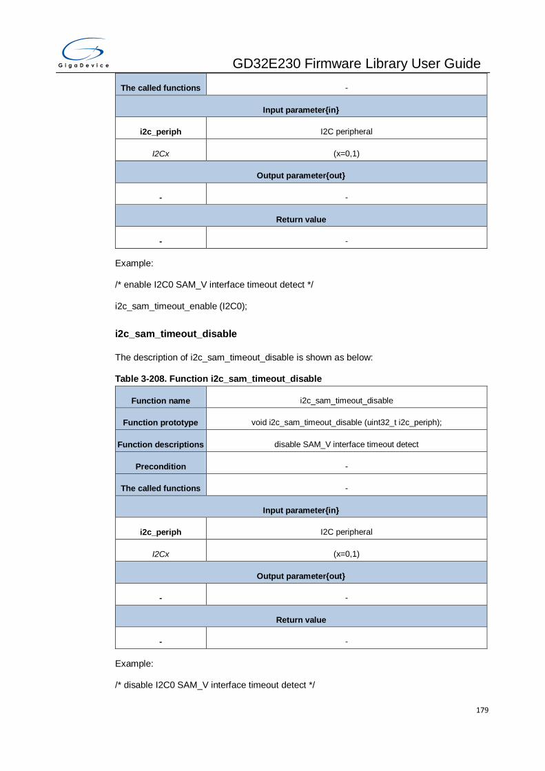
GD32E230 Firmware Library User Guide
179
The called functions -
Input parameter{in}
i2c_periph I2C peripheral
I2Cx (x=0,1)
Output parameter{out}
- -
Return value
- -
Example:
/* enable I2C0 SAM_V interface timeout detect */
i2c_sam_timeout_enable (I2C0);
i2c_sam_timeout_disable
The description of i2c_sam_timeout_disable is shown as below:
Table 3-208. Function i2c_sam_timeout_disable
Function name i2c_sam_timeout_disable
Function prototype void i2c_sam_timeout_disable (uint32_t i2c_periph);
Function descriptions disable SAM_V interface timeout detect
Precondition -
The called functions -
Input parameter{in}
i2c_periph I2C peripheral
I2Cx (x=0,1)
Output parameter{out}
- -
Return value
- -
Example:
/* disable I2C0 SAM_V interface timeout detect */

GD32E230 Firmware Library User Guide
180
i2c_sam_timeout_disable (I2C0);
i2c_flag_get
The description of i2c_flag_get is shown as below:
Table 3-209. Function i2c_flag_get
Function name i2c_flag_get
Function prototype FlagStatus i2c_flag_get(uint32_t i2c_periph, i2c_flag_enum flag)
Function descriptions check I2C flag is set or not
Precondition -
The called functions -
Input parameter{in}
i2c_periph I2C peripheral
I2Cx (x=0,1)
Input parameter{in}
flag specify get which flag
I2C_FLAG_SBSEND start condition send out
I2C_FLAG_ADDSEND address is sent in master mode or received and matches in slave mode
I2C_FLAG_BTC byte transmission finishes
I2C_FLAG_ADD10SEN
D header of 10-bit address is sent in master mode
I2C_FLAG_STPDET stop condition detected in slave mode
I2C_FLAG_RBNE I2C_DATA is not Empty during receiving
I2C_FLAG_TBE I2C_DATA is empty during transmitting
I2C_FLAG_BERR a bus error occurs indication a unexpected start or stop condition on I2C
bus
I2C_FLAG_LOSTARB arbitration lost in master mode
I2C_FLAG_AERR acknowledge error
I2C_FLAG_OUERR overrun or underrun situation occurs in slave mode
I2C_FLAG_PECERR PEC error when receiving data
I2C_FLAG_SMBTO timeout signal in SMBus mode

GD32E230 Firmware Library User Guide
181
I2C_FLAG_SMBALT SMBus alert status
I2C_FLAG_MASTER a flag indicating whether I2C block is in master or slave mode
I2C_FLAG_I2CBSY busy flag
I2C_FLAG_TR whether the I2C is a transmitter or a receiver
I2C_FLAG_RXGC general call address (00h) received
I2C_FLAG_DEFSMB default address of SMBus device
I2C_FLAG_HSTSMB SMBus host header detected in slave mode
I2C_FLAG_DUMOD dual flag in slave mode indicating which address is matched in dual-address
mode
I2C_FLAG_TFF txframe fall flag
I2C_FLAG_TFR txframe rise flag
I2C_FLAG_RFF rxframe fall flag
I2C_FLAG_RFR rxframe rise flag
Output parameter{out}
- -
Return value
FlagStatus SET / RESET
Example:
/* check whether start condition send out */
FlagStatus flag_state = RESET;
flag_state = i2c_flag_get (I2C0, I2C_FLAG_SBSEND);
i2c_flag_clear
The description of i2c_flag_clear is shown as below:
Table 3-210. Function i2c_flag_clear
Function name i2c_flag_clear
Function prototype void i2c_flag_clear(uint32_t i2c_periph, i2c_flag_enum flag)
Function descriptions clear I2C flag
Precondition -
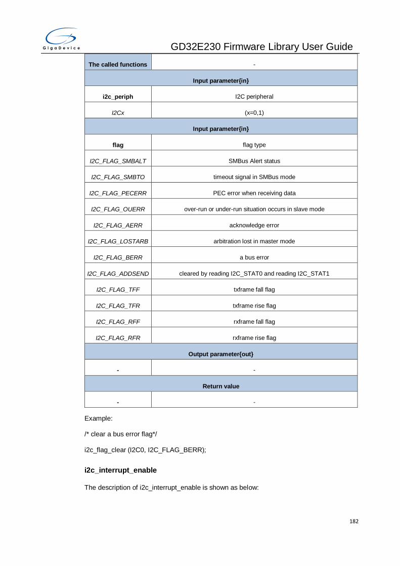
GD32E230 Firmware Library User Guide
182
The called functions -
Input parameter{in}
i2c_periph I2C peripheral
I2Cx (x=0,1)
Input parameter{in}
flag flag type
I2C_FLAG_SMBALT SMBus Alert status
I2C_FLAG_SMBTO timeout signal in SMBus mode
I2C_FLAG_PECERR PEC error when receiving data
I2C_FLAG_OUERR over-run or under-run situation occurs in slave mode
I2C_FLAG_AERR acknowledge error
I2C_FLAG_LOSTARB arbitration lost in master mode
I2C_FLAG_BERR a bus error
I2C_FLAG_ADDSEND cleared by reading I2C_STAT0 and reading I2C_STAT1
I2C_FLAG_TFF txframe fall flag
I2C_FLAG_TFR txframe rise flag
I2C_FLAG_RFF rxframe fall flag
I2C_FLAG_RFR rxframe rise flag
Output parameter{out}
- -
Return value
- -
Example:
/* clear a bus error flag*/
i2c_flag_clear (I2C0, I2C_FLAG_BERR);
i2c_interrupt_enable
The description of i2c_interrupt_enable is shown as below:

GD32E230 Firmware Library User Guide
183
Table 3-211. Function i2c_interrupt_enable
Function name i2c_interrupt_enable
Function prototype void i2c_interrupt_enable(uint32_t i2c_periph, i2c_interrupt_enum interrupt);
Function descriptions enable I2C interrupt
Precondition -
The called functions -
Input parameter{in}
i2c_periph I2C peripheral
I2Cx (x=0,1)
Input parameter{in}
inttype interrupt type
I2C_INT_ERR error interrupt enable
I2C_INT_EV event interrupt enable
I2C_INT_BUF buffer interrupt enable
I2C_INT_TFF txframe fall interrupt enable
I2C_INT_TFR txframe rise interrupt enable
I2C_INT_RFF rxframe fall interrupt enable
I2C_INT_RFR rxframe rise interrupt enable
Output parameter{out}
- -
Return value
- -
Example:
/* enable I2C0 event interrupt */
i2c_interrupt_enable (I2C0, I2C_INT_EV);
i2c_interrupt_disable
The description of i2c_interrupt_disable is shown as below:

GD32E230 Firmware Library User Guide
184
Table 3-212. Function i2c_interrupt_disable
Function name i2c_interrupt_disable
Function prototype void i2c_interrupt_disable(uint32_t i2c_periph, i2c_interrupt_enum
interrupt);
Function descriptions disable I2C interrupt
Precondition -
The called functions -
Input parameter{in}
i2c_periph I2C peripheral
I2Cx (x=0,1)
Input parameter{in}
inttype interrupt type
I2C_INT_ERR error interrupt disable
I2C_INT_EV event interrupt disable
I2C_INT_BUF buffer interrupt disable
I2C_INT_TFF txframe fall interrupt enable
I2C_INT_TFR txframe rise interrupt enable
I2C_INT_RFF rxframe fall interrupt enable
I2C_INT_RFR rxframe rise interrupt enable
Output parameter{out}
- -
Return value
- -
Example:
/* disable I2C0 event interrupt */
i2c_interrupt_disable (I2C0, I2C_INT_EV);
i2c_interrupt_flag_get
The description of i2c_interrupt_flag_get is shown as below:

GD32E230 Firmware Library User Guide
185
Table 3-213. Function i2c_interrupt_flag_get
Function name i2c_interrupt_flag_get
Function prototype FlagStatus i2c_interrupt_flag_get(uint32_t i2c_periph,
i2c_interrupt_flag_enum int_flag)
Function descriptions check I2C interrupt flag
Precondition -
The called functions -
Input parameter{in}
i2c_periph I2C peripheral
I2Cx (x=0,1)
Input parameter{in}
int_flag interrupt flag
I2C_INT_FLAG_SBSE
ND start condition sent out in master mode interrupt flag
I2C_INT_FLAG_ADDS
END
address is sent in master mode or received and matches in slave mode
interrupt flag
I2C_INT_FLAG_BTC byte transmission finishes
I2C_INT_FLAG_ADD10
SEND header of 10-bit address is sent in master mode interrupt flag
I2C_INT_FLAG_STPD
ET stop condition detected in slave mode interrupt flag
I2C_INT_FLAG_RBNE I2C_DATA is not Empty during receiving interrupt flag
I2C_INT_FLAG_TBE I2C_DATA is empty during transmitting interrupt flag
I2C_INT_FLAG_BERR a bus error occurs indication a unexpected start or stop condition on I2C
bus interrupt flag
I2C_INT_FLAG_LOSTA
RB arbitration lost in master mode interrupt flag
I2C_INT_FLAG_AERR acknowledge error interrupt flag
I2C_INT_FLAG_OUER
R over-run or under-run situation occurs in slave mode interrupt flag
I2C_INT_FLAG_PECE
RR PEC error when receiving data interrupt flag

GD32E230 Firmware Library User Guide
186
I2C_INT_FLAG_SMBT
O timeout signal in SMBus mode interrupt flag
I2C_INT_FLAG_SMBA
LT SMBus Alert status interrupt flag
I2C_INT_FLAG_TFF txframe fall interrupt flag
I2C_INT_FLAG_TFR txframe rise interrupt flag
I2C_INT_FLAG_RFF rxframe fall interrupt flag
I2C_INT_FLAG_RFR rxframe rise interrupt flag
Output parameter{out}
- -
Return value
FlagStatus SET / RESET
Example:
/* check the byte transmission finishes interrupt flag is set or not*/
FlagStatus flag_state = RESET;
flag_state = i2c_interrupt_flag_get (I2C0, I2C_INT_FLAG_BTC);
i2c_interrupt_flag_clear
The description of i2c_interrupt_flag_clear is shown as below:
Table 3-214. Function i2c_interrupt_flag_clear
Function name i2c_interrupt_flag_clear
Function prototype void i2c_interrupt_flag_clear(uint32_t i2c_periph, i2c_interrupt_flag_enum
int_flag);
Function descriptions clear I2C interrupt flag
Precondition -
The called functions -
Input parameter{in}
i2c_periph I2C peripheral
I2Cx (x=0,1)
Input parameter{in}

GD32E230 Firmware Library User Guide
187
intflag interrupt flag
I2C_INT_FLAG_ADDS
END
address is sent in master mode or received and matches in slave mode
interrupt flag
I2C_INT_FLAG_BERR a bus error occurs indication a unexpected start or stop condition on I2C
bus interrupt flag
I2C_INT_FLAG_LOSTA
RB arbitration lost in master mode interrupt flag
I2C_INT_FLAG_AERR acknowledge error interrupt flag
I2C_INT_FLAG_OUER
R over-run or under-run situation occurs in slave mode interrupt flag
I2C_INT_FLAG_PECE
RR PEC error when receiving data interrupt flag
I2C_INT_FLAG_SMBT
O timeout signal in SMBus mode interrupt flag
I2C_INT_FLAG_SMBA
LT SMBus Alert status interrupt flag
I2C_INT_FLAG_TFF txframe fall interrupt flag
I2C_INT_FLAG_TFR txframe rise interrupt flag
I2C_INT_FLAG_RFF rxframe fall interrupt flag
I2C_INT_FLAG_RFR rxframe rise interrupt flag
Output parameter{out}
- -
Return value
- -
Example:
/* clear the acknowledge error interrupt flag */
i2c_interrupt_flag_clear (I2C0, I2C_INT_FLAG_AERR);
3.12. MISC
MISC is a software package that provide the interfaces for NVIC and SysTick.The NVIC and
SysTick registers are listed in chapter 3.12.1, the MISC firmware functions are introduced in
chapter 3.12.2.

GD32E230 Firmware Library User Guide
188
3.12.1. Descriptions of Peripheral registers
Table 3-215. NVIC Registers
Registers Descriptions
ISER(1) Interrupt Set Enable Register
ICER(1) Interrupt Clear Enable Register
ISPR(1) Interrupt Set Pending Register
ICPR(1) Interrupt Clear Pending Register
IABR(1) Interrupt Active bit Register
ITNS(1) Interrupt Non-Secure State Register
IPR(1) Interrupt Priority Register
CPUID(2) CPUID Base Register
ICSR(2) Interrupt Control and State Register
VTOR(2) Vector Table Offset Register
AIRCR(2) Application Interrupt and Reset Control Register
SCR(2) System Control Register
CCR(2) Configuration Control Register
SHPR(2) System Handlers Priority Registers
SHCSR(2) System Handler Control and State Register
1. refer to the structure NVIC_Type, is defined in the core_cm3.h file
2. refer to the structure SCB_Type, is defined in the core_cm3.h file
Table 3-216. SysTick Registers
Registers Descriptions
CTRL(1) SysTick Control and Status Register
LOAD(1) SysTick Reload Value Register
VAL(1) SysTick Current Value Register
CALIB(1) SysTick Calibration Register
1. refer to the structure SysTick_Type, is defined in the core_cm3.h file

GD32E230 Firmware Library User Guide
189
3.12.2. Descriptions of Peripheral functions
Enum IRQn_Type
Table 3-217. IRQn_Type
Member name Function description
WWDGT_IRQn window watchDog timer interrupt
LVD_IRQn LVD through EXTI line detect interrupt
TAMPER_IRQn tamper through EXTI line detect
RTC_IRQn RTC through EXTI line interrupt
FMC_IRQn FMC interrupt
RCU_CTC_IRQn RCU and CTC interrupt
EXTI0_IRQn EXTI line 0 interrupts
EXTI1_IRQn EXTI line 1 interrupts
EXTI2_IRQn EXTI line 2 interrupts
EXTI3_IRQn EXTI line 3 interrupts
EXTI4_IRQn EXTI line 4 interrupts
DMA0_Channel0_IRQn DMA0 channel0 interrupt
DMA0_Channel1_IRQn DMA0 channel1 interrupt
DMA0_Channel2_IRQn DMA0 channel2 interrupt
DMA0_Channel3_IRQn DMA0 channel3 interrupt
DMA0_Channel4_IRQn DMA0 channel4 interrupt
DMA0_Channel5_IRQn DMA0 channel5 interrupt
DMA0_Channe6_IRQn DMA0 channel6 interrupt
ADC0_1_IRQn ADC0 and ADC1 interrupt
CAN0_TX_IRQn CAN0 transmit interrupts
CAN0_RX0_IRQn CAN0 receive0 interrupts
CAN0_RX1_IRQn CAN0 receive1 interrupts
CAN0_EWMC_IRQn CAN0 EWMC interrupts
EXTI5_9_IRQn EXTI[9:5] interrupts
TIMER0_BRK_TIMER8_IRQn TIMER0 break and TIMER8 interrupts
TIMER0_UP_TIMER9_IRQn TIMER0 update and TIMER9 interrupts
TIMER0_TRG_CMT_TIMER10_IRQn TIMER0 trigger and commutation and TIMER10 interrupts
TIMER0_Channel_IRQn TIMER0 channel capture compare interrupt
TIMER1_IRQn TIMER1 interrupt
TIMER2_IRQn TIMER2 interrupt
TIMER3_IRQn TIMER3 interrupt
I2C0_EV_IRQn I2C0 event interrupt
I2C0_ER_IRQn I2C0 error interrupt
I2C1_EV_IRQn I2C1 event interrupt
I2C1_ER_IRQn I2C1 error interrupt
SPI0_IRQn SPI0 interrupt

GD32E230 Firmware Library User Guide
190
Member name Function description
SPI1_IRQn SPI1 interrupt
USART0_IRQn USART0 interrupt
USART1_IRQn USART1 interrupt
USART2_IRQn USART2 interrupt
EXTI10_15_IRQn EXTI[15:10] interrupts
RTC_Alarm_IRQn RTC alarm interrupt
USBFS_WKUP_IRQn USBFS wakeup interrupt
TIMER7_BRK_TIMER11_IRQn TIMER7 break and TIMER11 interrupts
TIMER7_UP_TIMER12_IRQn TIMER7 update and TIMER12 interrupts
TIMER7_TRG_CMT_TIMER13_IRQn TIMER7 trigger and commutation and TIMER13 interrupts
TIMER7_Channel_IRQn TIMER7 channel capture compare interrupt
EXMC_IRQn EXMC global interrupt
TIMER4_IRQn TIMER4 global interrupt
SPI2_IRQn SPI2 global interrupt
UART3_IRQn UART3 global interrupt
UART4_IRQn UART4 global interrupt
TIMER5_IRQn TIMER5 global interrupt
TIMER6_IRQn TIMER6 global interrupt
DMA1_Channel0_IRQn DMA1 channel0 global interrupt
DMA1_Channel1_IRQn DMA1 channel1 global interrupt
DMA1_Channel2_IRQn DMA1 channel2 global interrupt
DMA1_Channel3_IRQn DMA1 channel3 global interrupt
DMA1_Channel4_IRQn DMA1 channel4 global interrupt
CAN1_TX_IRQn CAN1 transmit interrupt
CAN1_RX0_IRQn CAN1 receive0 interrupt
CAN1_RX1_IRQn CAN1 receive1 interrupt
CAN1_EWMC_IRQn CAN1 EWMC interrupt
USBFS_IRQn USBFS global interrupt
MISC firmware functions are listed in the table shown as below:
Table 3-218. MISC firmware function
Function name Function description
nvic_irq_enable enable NVIC interrupt request
nvic_irq_disable disable NVIC interrupt request
nvic_system_reset initiates a system reset request to reset the MCU
nvic_vector_table_set set the NVIC vector table address
system_lowpower_set set the state of the low power mode
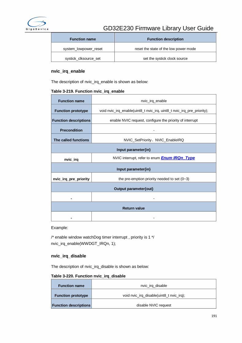
GD32E230 Firmware Library User Guide
191
Function name Function description
system_lowpower_reset reset the state of the low power mode
systick_clksource_set set the systick clock source
nvic_irq_enable
The description of nvic_irq_enable is shown as below:
Table 3-219. Function nvic_irq_enable
Function name nvic_irq_enable
Function prototype void nvic_irq_enable(uint8_t nvic_irq, uint8_t nvic_irq_pre_priority);
Function descriptions enable NVIC request, configure the priority of interrupt
Precondition -
The called functions NVIC_SetPriority、NVIC_EnableIRQ
Input parameter{in}
nvic_irq NVIC interrupt, refer to enum Enum IRQn_Type
Input parameter{in}
nvic_irq_pre_priority the pre-emption priority needed to set (0~3)
Output parameter{out}
- -
Return value
- -
Example:
/* enable window watchDog timer interrupt , priority is 1 */
nvic_irq_enable(WWDGT_IRQn, 1);
nvic_irq_disable
The description of nvic_irq_disable is shown as below:
Table 3-220. Function nvic_irq_disable
Function name nvic_irq_disable
Function prototype void nvic_irq_disable(uint8_t nvic_irq);
Function descriptions disable NVIC request

GD32E230 Firmware Library User Guide
192
Precondition -
The called functions -
Input parameter{in}
nvic_irq NVIC interrupt, refer to enumEnum IRQn_Type
Output parameter{out}
- -
Return value
- -
Example:
/* disable window watchDog timer interrupt */
nvic_irq_disable(WWDGT_IRQn);
nvic_system_reset
The description of nvic_system_reset is shown as below:
Table 3-221. Function nvic_system_reset
Function name nvic_system_reset
Function prototype void nvic_system_reset (void);
Function descriptions initiates a system reset request to reset the MCU
Precondition -
The called functions NVIC_SystemReset
Input parameter{in}
nvic_irq NVIC interrupt, refer to enumEnum IRQn_Type
Output parameter{out}
- -
Return value
- -
Example:
/* reset the MCU*/
nvic_system_reset();
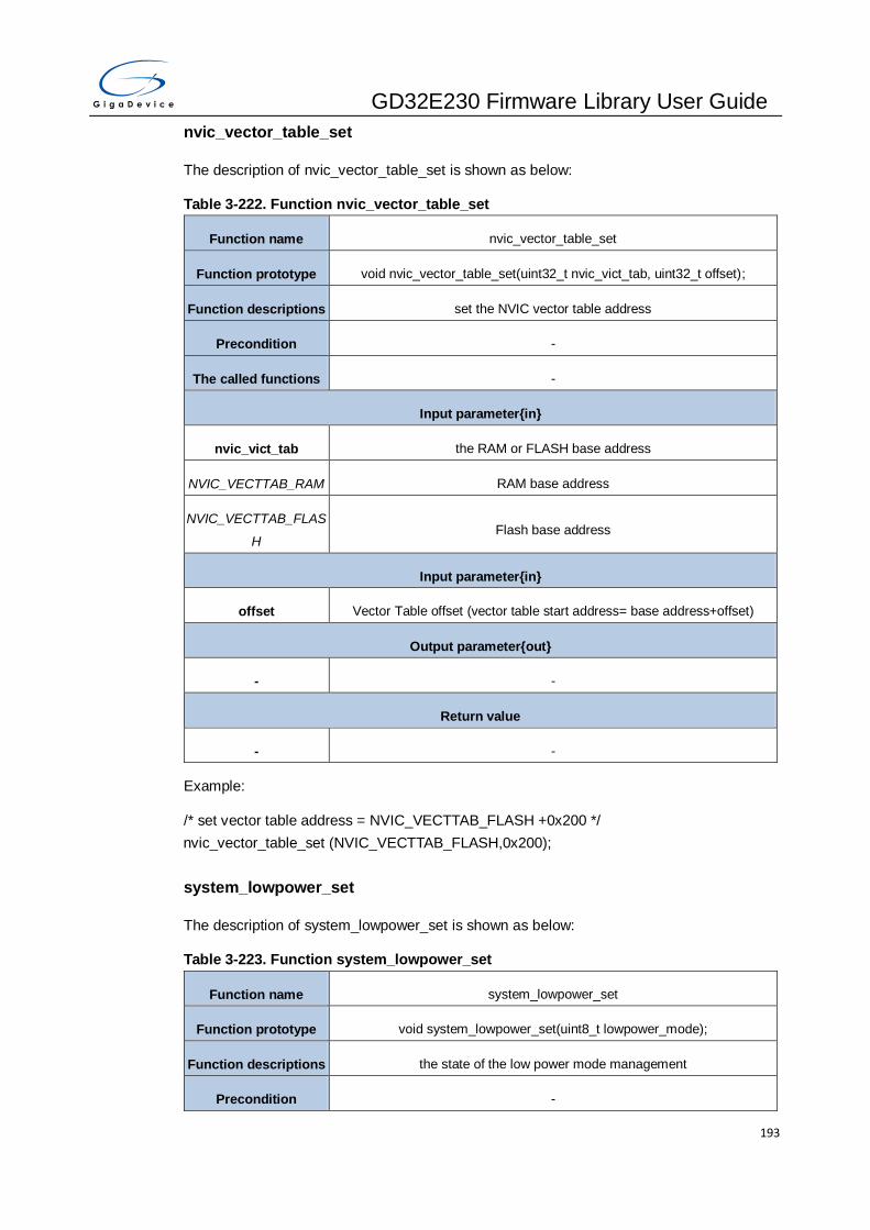
GD32E230 Firmware Library User Guide
193
nvic_vector_table_set
The description of nvic_vector_table_set is shown as below:
Table 3-222. Function nvic_vector_table_set
Function name nvic_vector_table_set
Function prototype void nvic_vector_table_set(uint32_t nvic_vict_tab, uint32_t offset);
Function descriptions set the NVIC vector table address
Precondition -
The called functions -
Input parameter{in}
nvic_vict_tab the RAM or FLASH base address
NVIC_VECTTAB_RAM RAM base address
NVIC_VECTTAB_FLAS
H Flash base address
Input parameter{in}
offset Vector Table offset (vector table start address= base address+offset)
Output parameter{out}
- -
Return value
- -
Example:
/* set vector table address = NVIC_VECTTAB_FLASH +0x200 */
nvic_vector_table_set (NVIC_VECTTAB_FLASH,0x200);
system_lowpower_set
The description of system_lowpower_set is shown as below:
Table 3-223. Function system_lowpower_set
Function name system_lowpower_set
Function prototype void system_lowpower_set(uint8_t lowpower_mode);
Function descriptions the state of the low power mode management
Precondition -

GD32E230 Firmware Library User Guide
194
The called functions -
Input parameter{in}
lowpower_mode the low power mode state
SCB_LPM_SLEEP_EXI
T_ISR
if chose this para, the system always enter low power mode by exiting from
ISR
SCB_LPM_DEEPSLEE
P
if chose this para, the system will enter the DEEPSLEEP mode
SCB_LPM_WAKE_BY_
ALL_INT
if chose this para, the lowpower mode can be woke up by all the enable and
disable interrupts
Output parameter{out}
- -
Return value
- -
Example:
/* the system always enter low power mode by exiting from ISR */
system_lowpower_set (SCB_LPM_SLEEP_EXIT_ISR);
system_lowpower_reset
The description of system_lowpower_reset is shown as below:
Table 3-224. Function system_lowpower_reset
Function name system_lowpower_reset
Function prototype void system_lowpower_reset(uint8_t lowpower_mode);
Function descriptions the state of the low power mode management
Precondition -
The called functions -
Input parameter{in}
lowpower_mode the low power mode state
SCB_LPM_SLEEP_EXI
T_ISR
if chose this para, the system will exit low power mode by exiting from ISR
SCB_LPM_DEEPSLEE
P
if chose this para, the system will enter the SLEEP mode

GD32E230 Firmware Library User Guide
195
SCB_LPM_WAKE_BY_
ALL_INT
if chose this para, the lowpower mode only can be woke up by the enable
interrupts
Output parameter{out}
- -
Return value
- -
Example:
/* the system will exit low power mode by exiting from ISR */
system_lowpower_reset (SCB_LPM_SLEEP_EXIT_ISR);
systick_clksource_set
The description of systick_clksource_set is shown as below:
Table 3-225. Function systick_clksource_set
Function name systick_clksource_set
Function prototype void systick_clksource_set(uint32_t systick_clksource);
Function descriptions set the systick clock source
Precondition -
The called functions -
Input parameter{in}
systick_clksource the systick clock source needed to choose
SYSTICK_CLKSOURC
E_HCLK
systick clock source is from HCLK
SYSTICK_CLKSOURC
E_HCLK_DIV8
systick clock source is from HCLK/8
Output parameter{out}
- -
Return value
- -
Example:
/* systick clock source is HCLK/8 */
systick_clksource_set (SYSTICK_CLKSOURCE_HCLK_DIV8);
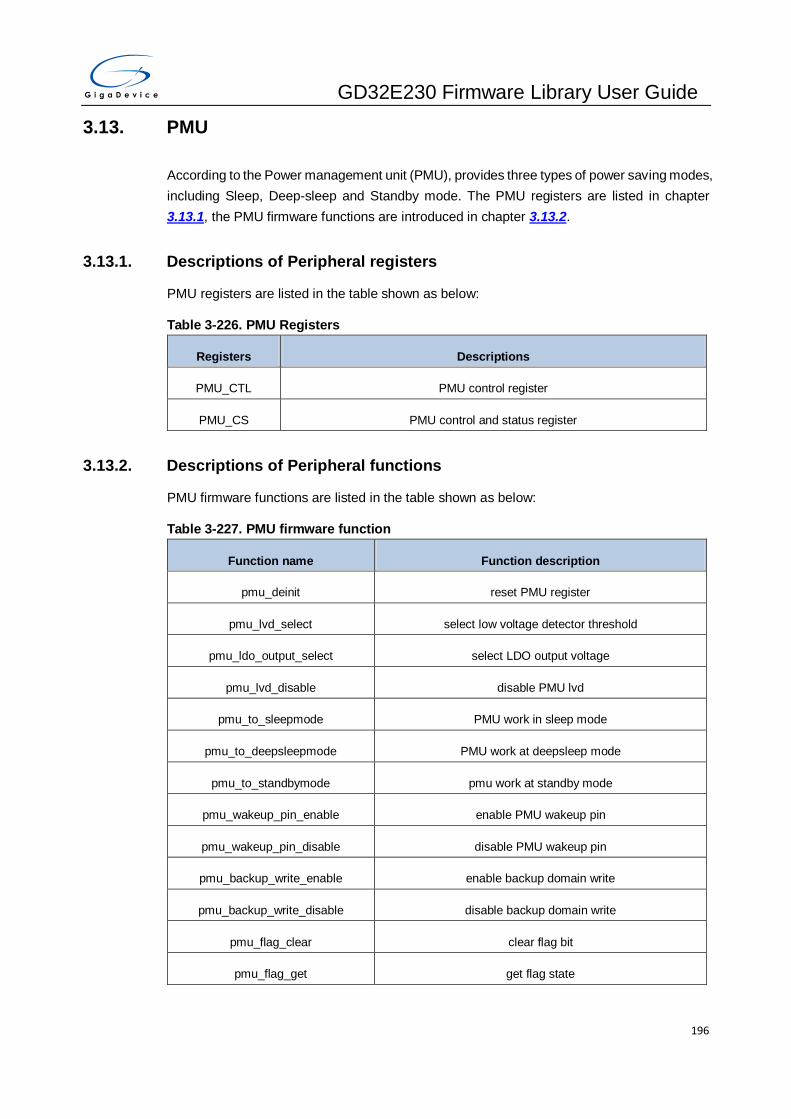
GD32E230 Firmware Library User Guide
196
3.13. PMU
According to the Power management unit (PMU), provides three types of power saving modes,
including Sleep, Deep-sleep and Standby mode. The PMU registers are listed in chapter
3.13.1, the PMU firmware functions are introduced in chapter 3.13.2.
3.13.1. Descriptions of Peripheral registers
PMU registers are listed in the table shown as below:
Table 3-226. PMU Registers
Registers Descriptions
PMU_CTL PMU control register
PMU_CS PMU control and status register
3.13.2. Descriptions of Peripheral functions
PMU firmware functions are listed in the table shown as below:
Table 3-227. PMU firmware function
Function name Function description
pmu_deinit reset PMU register
pmu_lvd_select select low voltage detector threshold
pmu_ldo_output_select select LDO output voltage
pmu_lvd_disable disable PMU lvd
pmu_to_sleepmode PMU work in sleep mode
pmu_to_deepsleepmode PMU work at deepsleep mode
pmu_to_standbymode pmu work at standby mode
pmu_wakeup_pin_enable enable PMU wakeup pin
pmu_wakeup_pin_disable disable PMU wakeup pin
pmu_backup_write_enable enable backup domain write
pmu_backup_write_disable disable backup domain write
pmu_flag_clear clear flag bit
pmu_flag_get get flag state
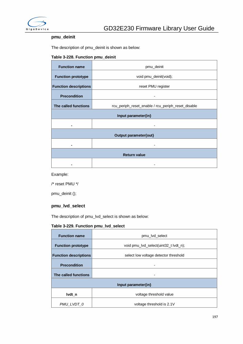
GD32E230 Firmware Library User Guide
197
pmu_deinit
The description of pmu_deinit is shown as below:
Table 3-228. Function pmu_deinit
Function name pmu_deinit
Function prototype void pmu_deinit(void);
Function descriptions reset PMU register
Precondition -
The called functions rcu_periph_reset_enable / rcu_periph_reset_disable
Input parameter{in}
- -
Output parameter{out}
- -
Return value
- -
Example:
/* reset PMU */
pmu_deinit ();
pmu_lvd_select
The description of pmu_lvd_select is shown as below:
Table 3-229. Function pmu_lvd_select
Function name pmu_lvd_select
Function prototype void pmu_lvd_select(uint32_t lvdt_n);
Function descriptions select low voltage detector threshold
Precondition -
The called functions -
Input parameter{in}
lvdt_n voltage threshold value
PMU_LVDT_0 voltage threshold is 2.1V

GD32E230 Firmware Library User Guide
198
PMU_LVDT_1 voltage threshold is 2.3V
PMU_LVDT_2 voltage threshold is 2.4V
PMU_LVDT_3 voltage threshold is 2.6V
PMU_LVDT_4 voltage threshold is 2.7V
PMU_LVDT_5 voltage threshold is 2.9V
PMU_LVDT_6 voltage threshold is 3.0V
PMU_LVDT_7 voltage threshold is 3.1V
Output parameter{out}
- -
Return value
- -
Example:
/* select low voltage detector threshold as 3.1V */
pmu_lvd_select (PMU_LVDT_7);
pmu_ldo_output_select
The description of pmu_ldo_output_select is shown as below:
Table 3-230. Function pmu_ldo_output_select
Function name pmu_ldo_output_select
Function prototype void pmu_ldo_output_select(uint32_t ldo_output);
Function descriptions select LDO output voltage
Precondition -
The called functions -
Input parameter{in}
ldo_output output voltage mode
PMU_LDOVS_LOW LDO output voltage low mode
PMU_LDOVS_HIGH LDO output voltage high mode
Output parameter{out}
- -

GD32E230 Firmware Library User Guide
199
Return value
- -
Example:
/* select output low voltage mode */
pmu_ldo_output_select (PMU_LDOVS_LOW);
pmu_lvd_disable
The description of pmu_lvd_disable is shown as below:
Table 3-231. Function pmu_lvd_disable
Function name pmu_lvd_disable
Function prototype void pmu_lvd_disable (void);
Function descriptions disable PMU lvd
Precondition -
The called functions -
Input parameter{in}
- -
Output parameter{out}
- -
Return value
- -
Example:
/* disable PMU lvd */
pmu_lvd_disable ();
pmu_to_sleepmode
The description of pmu_to_sleepmode is shown as below:
Table 3-232. Function pmu_to_sleepmode
Function name pmu_to_sleepmode
Function prototype void pmu_to_sleepmode(uint8_t sleepmodecmd);
Function descriptions PMU work at sleep mode

GD32E230 Firmware Library User Guide
200
Precondition -
The called functions -
Input parameter{in}
sleepmodecmd command to enter sleep mode
WFI_CMD use WFI command
WFE_CMD use WFE command
Output parameter{out}
- -
Return value
- -
Example:
/* PMU work at sleep mode */
pmu_to_sleepmode (WFI_CMD);
pmu_to_deepsleepmode
The description of pmu_to_deepsleepmode is shown as below:
Table 3-233. Function pmu_to_deepsleepmode
Function name pmu_to_deepsleepmode
Function prototype void pmu_to_deepsleepmode(uint32_t ldo,uint8_t deepsleepmodecmd);
Function descriptions PMU work at deepsleep mode
Precondition -
The called functions -
Input parameter{in}
ldo ldo work mode
PMU_LDO_NORMAL LDO operates normally when pmu enter deepsleep mode
PMU_LDO_LOWPOW
ER LDO work at low power mode when pmu enter deepsleep mode
Input parameter{in}
deepsleepmodecmd command to enter deepsleep mode

GD32E230 Firmware Library User Guide
201
WFI_CMD use WFI command
WFE_CMD use WFE command
Output parameter{out}
- -
Return value
- -
Example:
/* PMU work at deepsleep mode */
pmu_to_deepsleepmode (PMU_LDO_NORMAL, WFI_CMD);
pmu_to_standbymode
The description of pmu_to_standbymode is shown as below:
Table 3-234. Function pmu_to_standbymode
Function name pmu_to_standbymode
Function prototype void pmu_to_standbymode(uint8_t standbymodecmd);
Function descriptions pmu work at standby mode
Precondition -
The called functions -
Input parameter{in}
standbymodecmd command to enter standby mode
WFI_CMD use WFI command
WFE_CMD use WFE command
Output parameter{out}
- -
Return value
- -
Example:
/* PMU work at standby mode */
pmu_to_standby (WFI_CMD);

GD32E230 Firmware Library User Guide
202
pmu_wakeup_pin_enable
The description of pmu_wakeup_pin_enable is shown as below:
Table 3-235. Function pmu_wakeup_pin_enable
Function name pmu_wakeup_pin_enable
Function prototype void pmu_wakeup_pin_enable(uint32_t wakeup_pin);
Function descriptions enable wakeup pin
Precondition -
The called functions -
Input parameter{in}
wakeup_pin Wakeup pin
PMU_WAKEUP_PIN0 WKUP Pin 0 (PA0)
PMU_WAKEUP_PIN1 WKUP Pin 1 (PC13)
PMU_WAKEUP_PIN5 WKUP Pin 5 (PB5)
PMU_WAKEUP_PIN6 WKUP Pin 6 (PB15)
Output parameter{out}
- -
Return value
- -
Example:
/* enable wakeup pin6 */
pmu_wakeup_pin_enable (PMU_WAKEUP_PIN6);
pmu_wakeup_pin_disable
The description of pmu_wakeup_pin_disable is shown as below:
Table 3-236. Function pmu_wakeup_pin_disable
Function name pmu_wakeup_pin_disable
Function prototype void pmu_wakeup_pin_disable(uint32_t wakeup_pin);
Function descriptions disable wakeup pin
Precondition -

GD32E230 Firmware Library User Guide
203
The called functions -
Input parameter{in}
wakeup_pin Wakeup pin
PMU_WAKEUP_PIN0 WKUP Pin 0 (PA0)
PMU_WAKEUP_PIN1 WKUP Pin 1 (PC13)
PMU_WAKEUP_PIN5 WKUP Pin 5 (PB5)
PMU_WAKEUP_PIN6 WKUP Pin 6 (PB15)
Output parameter{out}
- -
Return value
- -
Example:
/* disable wakeup pin6 */
pmu_wakeup_pin_disable (PMU_WAKEUP_PIN6);
pmu_backup_write_enable
The description of pmu_backup_write_enable is shown as below:
Table 3-237. Function pmu_backup_write_enable
Function name pmu_backup_write_enable
Function prototype void pmu_backup_write_enable (void);
Function descriptions enable backup domain write
Precondition -
The called functions -
Input parameter{in}
- -
Output parameter{out}
- -
Return value
- -

GD32E230 Firmware Library User Guide
204
Example:
/* enable backup domain write */
pmu_backup_write_enable ();
pmu_backup_write_disable
The description of pmu_backup_write_disable is shown as below:
Table 3-238. Function pmu_backup_write_disable
Function name pmu_backup_write_disable
Function prototype void pmu_backup_write_disable (void);
Function descriptions disable backup domain write
Precondition -
The called functions -
Input parameter{in}
- -
Output parameter{out}
- -
Return value
- -
Example:
/* disable backup domain write */
pmu_backup_write_disable ();
pmu_flag_clear
The description of pmu_flag_clear is shown as below:
Table 3-239. Function pmu_flag_clear
Function name pmu_flag_clear
Function prototype void pmu_flag_clear(uint32_t flag_clear);
Function descriptions clear flag bit
Precondition -
The called functions -

GD32E230 Firmware Library User Guide
205
Input parameter{in}
flag_clear flag
PMU_FLAG_RESET_
WAKEUP reset wakeup flag
PMU_FLAG_RESET_S
TANDBY reset standby flag
Output parameter{out}
- -
Return value
- -
Example:
/* clear flag bit */
pmu_flag_clear (PMU_FLAG_RESET_WAKEUP);
pmu_flag_get
The description of pmu_flag_get is shown as below:
Table 3-240. Function pmu_flag_get
Function name pmu_flag_get
Function prototype FlagStatus pmu_flag_get(uint32_t flag);
Function descriptions get flag state
Precondition -
The called functions -
Input parameter{in}
flag flag
PMU_FLAG_WAKEUP wakeup flag
PMU_FLAG_STANDBY standby flag
PMU_FLAG_LVD lvd flag
Output parameter{out}
- -
Return value

GD32E230 Firmware Library User Guide
206
FlagStatus SET or RESET
Example:
/* get flag state */
FlagStatus status;
status = pmu_flag_get (PMU_FLAG_WAKEUP);
3.14. RCU
RCU is the reset and clock unit. Reset Control includes the control of three kinds of reset:
power reset, system reset and backup domain reset. The Clock Control unit provides a range
of frequencies and clock functions. The RCU registers are listed in chapter 3.14.1, the RCU
firmware functions are introduced in chapter 3.14.2.
3.14.1. Descriptions of Peripheral registers
Table 3-241. RCU Registers
Registers Descriptions
RCU_CTL0 Control register 0
RCU_CFG0 Clock configuration register 0
RCU_INT Clock interrupt register
RCU_APB2RST APB2 reset register
RCU_APB1RST APB1 reset register
RCU_AHBEN AHB enable register
RCU_APB2EN APB2 enable register
RCU_APB1EN APB1 enable register
RCU_BDCTL Backup domain control register
RCU_RSTSCK Reset source/clock register
RCU_AHBRST AHB reset register
RCU_CFG1 Clock configuration register 1
RCU_CFG2 Clock configuration register 2
RCU_CTL1 Control register 1
RCU_VKEY Unlock voltage register

GD32E230 Firmware Library User Guide
207
Registers Descriptions
RCU_DSV Deep-sleep mode voltage register
3.14.2. Descriptions of Peripheral functions
Table 3-242. RCU firmware function
Function name Function description
rcu_deinit deinitialize the RCU
rcu_periph_clock_enable enable the peripherals clock
rcu_periph_clock_disable disable the peripherals clock
rcu_periph_clock_sleep_enable enable the peripherals clock when in sleep mode
rcu_periph_clock_sleep_disable disable the peripherals clock when in sleep mode
rcu_periph_reset_enable enable the peripherals reset
rcu_periph_reset_disable disable the peripheral reset
rcu_bkp_reset_enable enable the BKP domain reset
rcu_bkp_reset_disable disable the BKP domain reset
rcu_system_clock_source_config configure the system clock source
rcu_system_clock_source_get get the system clock source
rcu_ahb_clock_config configure the AHB clock prescaler selection
rcu_apb1_clock_config configure the APB1 clock prescaler selection
rcu_apb2_clock_config configure the APB2 clock prescaler selection
rcu_adc_clock_config configure the ADC clock source and prescaler selection
rcu_ckout_config configure the CK_OUT clock source and divider
rcu_pll_config configure the main PLL clock
rcu_usart_clock_config configure the usart clock
rcu_rtc_clock_config configure the RTC clock source selection
rcu_hxtal_prediv_config configure the HXTAL divider used as input of PLL
rcu_lxtal_drive_capability_config configure the LXTAL drive capability
rcu_flag_get get the clock stabilization and periphral reset flags
rcu_all_reset_flag_clear clear all the reset flag

GD32E230 Firmware Library User Guide
208
Function name Function description
rcu_interrupt_flag_get get the clock stabilization interrupt and ckm flags
rcu_interrupt_flag_clear clear the interrupt flags
rcu_interrupt_enable enable the stabilization interrupt
rcu_interrupt_disable disable the stabilization interrupt
rcu_osci_stab_wait wait for oscillator stabilization flags is SET or oscillator startup
is timeout
rcu_osci_on turn on the oscillator
rcu_osci_off turn off the oscillator
rcu_osci_bypass_mode_enable enable the oscillator bypass mode
rcu_osci_bypass_mode_disable disable the oscillator bypass mode
rcu_hxtal_clock_monitor_enable enable the HXTAL clock monitor
rcu_hxtal_clock_monitor_disable disable the HXTAL clock monitor
rcu_irc8m_adjust_value_set set the IRC8M adjust value
rcu_irc28m_adjust_value_set set the IRC28M adjust value
rcu_voltage_key_unlock unlock Deep-sleep mode voltage register
rcu_deepsleep_voltage_set set the deep-sleep mode voltage value
rcu_clock_freq_get get the system clock, bus clock frequency
rcu_deinit
The description of rcu_deinit is shown as below:
Table 3-243. Function rcu_deinit
Function name rcu_deinit
Function prototype void rcu_deinit(void);
Function descriptions deinitialize the RCU, reset the value of all RCU registers into initial values
Precondition -
The called functions -
Input parameter{in}
- -
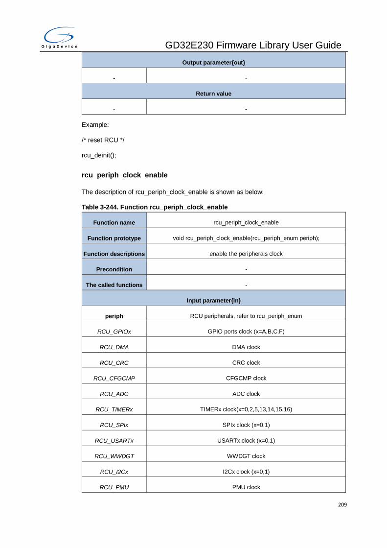
GD32E230 Firmware Library User Guide
209
Output parameter{out}
- -
Return value
- -
Example:
/* reset RCU */
rcu_deinit();
rcu_periph_clock_enable
The description of rcu_periph_clock_enable is shown as below:
Table 3-244. Function rcu_periph_clock_enable
Function name rcu_periph_clock_enable
Function prototype void rcu_periph_clock_enable(rcu_periph_enum periph);
Function descriptions enable the peripherals clock
Precondition -
The called functions -
Input parameter{in}
periph RCU peripherals, refer to rcu_periph_enum
RCU_GPIOx GPIO ports clock (x=A,B,C,F)
RCU_DMA DMA clock
RCU_CRC CRC clock
RCU_CFGCMP CFGCMP clock
RCU_ADC ADC clock
RCU_TIMERx TIMERx clock(x=0,2,5,13,14,15,16)
RCU_SPIx SPIx clock (x=0,1)
RCU_USARTx USARTx clock (x=0,1)
RCU_WWDGT WWDGT clock
RCU_I2Cx I2Cx clock (x=0,1)
RCU_PMU PMU clock

GD32E230 Firmware Library User Guide
210
RCU_RTC RTC clock
RCU_DBGMCU DBGMCU clock
Output parameter{out}
- -
Return value
- -
Example:
/* enable the USART0 clock */
rcu_periph_clock_enable(RCU_USART0);
rcu_periph_clock_disable
The description of rcu_periph_clock_disable is shown as below:
Table 3-245. Function rcu_periph_clock_disable
Function name rcu_periph_clock_disable
Function prototype void rcu_periph_clock_disable(rcu_periph_enum periph);
Function descriptions disable the peripherals clock
Precondition -
The called functions -
Input parameter{in}
periph RCU peripherals, refer to rcu_periph_enum
RCU_GPIOx GPIO ports clock (x=A,B,C,F)
RCU_DMA DMA clock
RCU_CRC CRC clock
RCU_CFGCMP CFGCMP clock
RCU_ADC ADC clock
RCU_TIMERx TIMERx clock(x=0,2,5,13,14,15,16)
RCU_SPIx SPIx clock (x=0,1)
RCU_USARTx USARTx clock (x=0,1)
RCU_WWDGT WWDGT clock

GD32E230 Firmware Library User Guide
211
RCU_I2Cx I2Cx clock (x=0,1)
RCU_PMU PMU clock
RCU_RTC RTC clock
RCU_DBGMCU DBGMCU clock
Output parameter{out}
- -
Return value
- -
Example:
/* disable the USART0 clock */
rcu_periph_clock_disable(RCU_USART0);
rcu_periph_clock_sleep_enable
The description of rcu_periph_clock_sleep_enable is shown as below:
Table 3-246. Function rcu_periph_clock_sleep_enable
Function name rcu_periph_clock_sleep_enable
Function prototype void rcu_periph_clock_sleep_enable(rcu_periph_sleep_enum periph);
Function descriptions enable the peripherals clock when in sleep mode
Precondition -
The called functions -
Input parameter{in}
periph RCU peripherals, refer to rcu_periph_sleep_enum
RCU_FMC_SLP FMC clock
RCU_SRAM_SLP SRAM clock
Output parameter{out}
- -
Return value
- -
Example:

GD32E230 Firmware Library User Guide
212
/* enable the FMC clock when in sleep mode */
rcu_periph_clock_sleep_enable(RCU_FMC_SLP);
rcu_periph_clock_sleep_disable
The description of rcu_periph_clock_sleep_disable is shown as below:
Table 3-247. Function rcu_periph_clock_sleep_disable
Function name rcu_periph_clock_sleep_disable
Function prototype void rcu_periph_clock_sleep_disable(rcu_periph_sleep_enum periph);
Function descriptions disable the peripherals clock when in sleep mode
Precondition -
The called functions -
Input parameter{in}
periph RCU peripherals, refer to rcu_periph_sleep_enum
RCU_FMC_SLP FMC clock
RCU_SRAM_SLP SRAM clock
Output parameter{out}
- -
Return value
- -
Example:
/* disable the FMC clock when in sleep mode */
rcu_periph_clock_sleep_disable(RCU_FMC_SLP);
rcu_periph_reset_enable
The description of rcu_periph_reset_enable is shown as below:
Table 3-248. Function rcu_periph_reset_enable
Function name rcu_periph_reset_enable
Function prototype void rcu_periph_reset_enable(rcu_periph_reset_enum periph_reset);
Function descriptions enable the peripherals reset
Precondition -
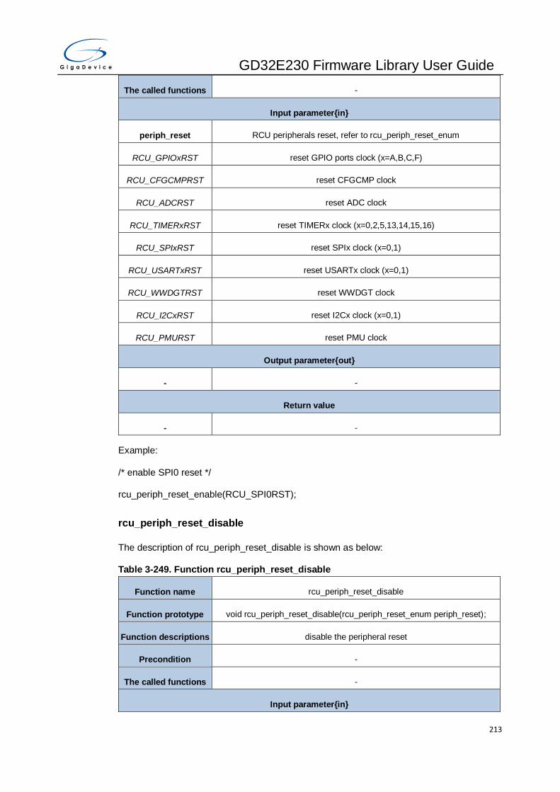
GD32E230 Firmware Library User Guide
213
The called functions -
Input parameter{in}
periph_reset RCU peripherals reset, refer to rcu_periph_reset_enum
RCU_GPIOxRST reset GPIO ports clock (x=A,B,C,F)
RCU_CFGCMPRST reset CFGCMP clock
RCU_ADCRST reset ADC clock
RCU_TIMERxRST reset TIMERx clock (x=0,2,5,13,14,15,16)
RCU_SPIxRST reset SPIx clock (x=0,1)
RCU_USARTxRST reset USARTx clock (x=0,1)
RCU_WWDGTRST reset WWDGT clock
RCU_I2CxRST reset I2Cx clock (x=0,1)
RCU_PMURST reset PMU clock
Output parameter{out}
- -
Return value
- -
Example:
/* enable SPI0 reset */
rcu_periph_reset_enable(RCU_SPI0RST);
rcu_periph_reset_disable
The description of rcu_periph_reset_disable is shown as below:
Table 3-249. Function rcu_periph_reset_disable
Function name rcu_periph_reset_disable
Function prototype void rcu_periph_reset_disable(rcu_periph_reset_enum periph_reset);
Function descriptions disable the peripheral reset
Precondition -
The called functions -
Input parameter{in}

GD32E230 Firmware Library User Guide
214
periph_reset RCU peripherals reset, refer to rcu_periph_reset_enum
RCU_GPIOxRST disable reset GPIO ports clock (x=A,B,C,F)
RCU_CFGCMPRST disable reset CFGCMP clock
RCU_ADCRST disable reset ADC clock
RCU_TIMERxRST disable reset TIMERx clock (x=0,2,5,13,14,15,16)
RCU_SPIxRST disable reset SPIx clock (x=0,1)
RCU_USARTxRST disable reset USARTx clock (x=0,1)
RCU_WWDGTRST disable reset WWDGT clock
RCU_I2CxRST disable reset I2Cx clock (x=0,1)
RCU_PMURST disable reset PMU clock
Output parameter{out}
- -
Return value
- -
Example:
/* disable SPI0 reset */
rcu_periph_reset_disable(RCU_SPI0RST);
rcu_bkp_reset_enable
The description of rcu_bkp_reset_enable is shown as below:
Table 3-250. Function rcu_bkp_reset_enable
Function name rcu_bkp_reset_enable
Function prototype void rcu_bkp_reset_enable(void);
Function descriptions enable the BKP domain reset
Precondition -
The called functions -
Input parameter{in}
- -
Output parameter{out}

GD32E230 Firmware Library User Guide
215
- -
Return value
- -
Example:
/* reset the BKP domain */
rcu_bkp_reset_enable();
rcu_bkp_reset_disable
The description of rcu_bkp_reset_disable is shown as below:
Table 3-251. Function rcu_bkp_reset_disable
Function name rcu_bkp_reset_disable
Function prototype void rcu_bkp_reset_disable(void);
Function descriptions disable the BKP domain reset
Precondition -
The called functions -
Input parameter{in}
- -
Output parameter{out}
- -
Return value
- -
Example:
/* disable the BKP domain reset */
rcu_bkp_reset_disable();
rcu_system_clock_source_config
The description of rcu_system_clock_source_config is shown as below:
Table 3-252. Function rcu_system_clock_source_config
Function name rcu_system_clock_source_config
Function prototype void rcu_system_clock_source_config(uint32_t ck_sys);

GD32E230 Firmware Library User Guide
216
Function descriptions configure the system clock source
Precondition -
The called functions -
Input parameter{in}
ck_sys system clock source select
RCU_CKSYSSRC_IRC
8M select CK_IRC8M as the CK_SYS source
RCU_CKSYSSRC_HX
TAL select CK_HXTAL as the CK_SYS source
RCU_CKSYSSRC_PLL select CK_PLL as the CK_SYS source
Output parameter{out}
- -
Return value
- -
Example:
/* configure the CK_HXTAL as the CK_SYS source */
rcu_system_clock_source_config(RCU_CKSYSSRC_HXTAL);
rcu_system_clock_source_get
The description of rcu_system_clock_source_get is shown as below:
Table 3-253. Function rcu_system_clock_source_get
Function name rcu_system_clock_source_get
Function prototype uint32_t rcu_system_clock_source_get(void);
Function descriptions get the system clock source
Precondition -
The called functions -
Input parameter{in}
- -
Output parameter{out}
- -
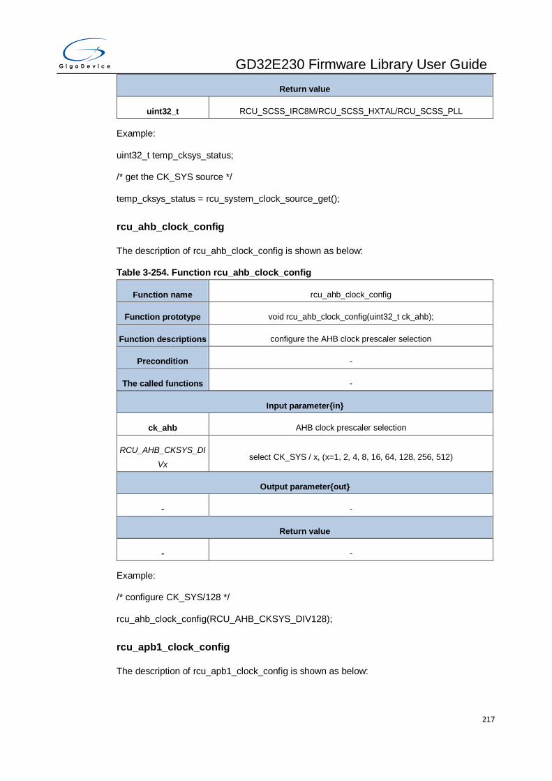
GD32E230 Firmware Library User Guide
217
Return value
uint32_t RCU_SCSS_IRC8M/RCU_SCSS_HXTAL/RCU_SCSS_PLL
Example:
uint32_t temp_cksys_status;
/* get the CK_SYS source */
temp_cksys_status = rcu_system_clock_source_get();
rcu_ahb_clock_config
The description of rcu_ahb_clock_config is shown as below:
Table 3-254. Function rcu_ahb_clock_config
Function name rcu_ahb_clock_config
Function prototype void rcu_ahb_clock_config(uint32_t ck_ahb);
Function descriptions configure the AHB clock prescaler selection
Precondition -
The called functions -
Input parameter{in}
ck_ahb AHB clock prescaler selection
RCU_AHB_CKSYS_DI
Vx select CK_SYS / x, (x=1, 2, 4, 8, 16, 64, 128, 256, 512)
Output parameter{out}
- -
Return value
- -
Example:
/* configure CK_SYS/128 */
rcu_ahb_clock_config(RCU_AHB_CKSYS_DIV128);
rcu_apb1_clock_config
The description of rcu_apb1_clock_config is shown as below:

GD32E230 Firmware Library User Guide
218
Table 3-255. Function rcu_apb1_clock_config
Function name rcu_apb1_clock_config
Function prototype void rcu_apb1_clock_config(uint32_t ck_apb1);
Function descriptions configure the APB1 clock prescaler selection
Precondition -
The called functions -
Input parameter{in}
ck_apb1 APB1 clock prescaler selection
RCU_APB1_CKAHB_D
IVx select (CK_AHB / x) as CK_APB1(x=1,2,4,8,16)
Output parameter{out}
- -
Return value
- -
Example:
/* configure CK_AHB/16 as CK_APB1 */
rcu_apb1_clock_config(RCU_APB1_CKAHB_DIV16);
rcu_apb2_clock_config
The description of rcu_apb2_clock_config is shown as below:
Table 3-256. Function rcu_apb2_clock_config
Function name rcu_apb2_clock_config
Function prototype void rcu_apb2_clock_config(uint32_t ck_apb2);
Function descriptions configure the APB2 clock prescaler selection
Precondition -
The called functions -
Input parameter{in}
ck_apb2 APB2 clock prescaler selection
RCU_APB2_CKAHB_D
IVx select (CK_AHB / x) as CK_APB2 clock(x=1,2,4,8,16)
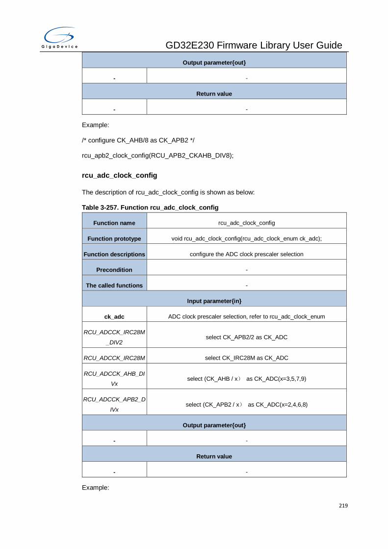
GD32E230 Firmware Library User Guide
219
Output parameter{out}
- -
Return value
- -
Example:
/* configure CK_AHB/8 as CK_APB2 */
rcu_apb2_clock_config(RCU_APB2_CKAHB_DIV8);
rcu_adc_clock_config
The description of rcu_adc_clock_config is shown as below:
Table 3-257. Function rcu_adc_clock_config
Function name rcu_adc_clock_config
Function prototype void rcu_adc_clock_config(rcu_adc_clock_enum ck_adc);
Function descriptions configure the ADC clock prescaler selection
Precondition -
The called functions -
Input parameter{in}
ck_adc ADC clock prescaler selection, refer to rcu_adc_clock_enum
RCU_ADCCK_IRC28M
_DIV2 select CK_APB2/2 as CK_ADC
RCU_ADCCK_IRC28M select CK_IRC28M as CK_ADC
RCU_ADCCK_AHB_DI
Vx select (CK_AHB / x) as CK_ADC(x=3,5,7,9)
RCU_ADCCK_APB2_D
IVx select (CK_APB2 / x) as CK_ADC(x=2,4,6,8)
Output parameter{out}
- -
Return value
- -
Example:

GD32E230 Firmware Library User Guide
220
/* configure the ADC prescaler factor */
rcu_adc_clock_config(RCU_CKADC_CKAPB2_DIV8);
rcu_ckout_config
The description of rcu_ckout_config is shown as below:
Table 3-258. Function rcu_ckout_config
Function name rcu_ckout_config
Function prototype void rcu_ckout_config(uint32_t ckout_src, uint32_t ckout_div);
Function descriptions configure the CK_OUT clock source and divoision factor
Precondition -
The called functions -
Input parameter{in}
ckout_src CK_OUT clock source selection
RCU_CKOUTSRC_NO
NE no clock selected
RCU_CKOUTSRC_IRC
28M select high speed 28M internal oscillator clock
RCU_CKOUTSRC_IRC
40K select high speed 40K internal oscillator clock
RCU_CKOUTSRC_LX
TAL select LXTAL clock
RCU_CKOUTSRC_CK
SYS select system clock CK_SYS
RCU_CKOUTSRC_IRC
8M select high speed 8M internal oscillator clock
RCU_CKOUTSRC_HX
TAL select HXTAL clock
RCU_CKOUTSRC_CK
PLL_DIV1 select CK_PLL clock
RCU_CKOUTSRC_CK
PLL_DIV2 Select(CK_PLL / 2)clock
Input parameter{in}

GD32E230 Firmware Library User Guide
221
ckout_div CK_OUT divider
RCU_CKOUT_DIVx CK_OUT is divided by x(x=1,2,4,8,16,32,64,128)
Output parameter{out}
- -
Return value
- -
Example:
/* configure the HXTAL as CK_OUT clock source */
rcu_ckout_config(RCU_CKOUTSRC_HXTAL);
rcu_pll_config
The description of rcu_pll_config is shown as below:
Table 3-259. Function rcu_pll_config
Function name rcu_pll_config
Function prototype void rcu_pll_config(uint32_t pll_src, uint32_t pll_mul);
Function descriptions configure the main PLL clock
Precondition -
The called functions -
Input parameter{in}
pll_src PLL clock source selection
RCU_PLLSRC_IRC8M
_DIV2 IRC8M/2 clock is selected as source clock of PLL
RCU_PLLSRC_HXTAL HXTAL is selected as source clock of PLL
Input parameter{in}
pll_mul PLL clock multiplication factor
RCU_PLL_MULx PLL source clock * x (x = 2..32)
Output parameter{out}
- -
Return value

GD32E230 Firmware Library User Guide
222
- -
Example:
/* configure the PLL */
rcu_pll_config(RCU_PLLSRC_HXTAL, RCU_PLL_MUL10);
rcu_usart_clock_config
The description of rcu_usart_clock_config is shown as below:
Table 3-260. Function rcu_usart_clock_config
Function name rcu_usart_clock_config
Function prototype void rcu_usart_clock_config(uint32_t ck_usart);
Function descriptions configure the USART clock source selection
Precondition -
The called functions -
Input parameter{in}
ck_usart USART clock source selection
RCU_USART0SRC_C
KAPB2 CK_USART0 select CK_APB2
RCU_USART0SRC_C
KSYS CK_USART0 select CK_SYS
RCU_USART0SRC_LX
TAL CK_USART0 select CK_LXTAL
RCU_USART0SRC_IR
C8M CK_USART0 select CK_IRC8M
Output parameter{out}
- -
Return value
- -
Example:
/* configure the LXTAL as USART0 clock */
rcu_usart_clock_config(RCU_USART0SRC_LXTAL);

GD32E230 Firmware Library User Guide
223
rcu_rtc_clock_config
The description of rcu_rtc_clock_config is shown as below:
Table 3-261. Function rcu_rtc_clock_config
Function name rcu_rtc_clock_config
Function prototype void rcu_rtc_clock_config(uint32_t rtc_clock_source);
Function descriptions configure the RTC clock source selection
Precondition -
The called functions -
Input parameter{in}
rtc_clock_source RTC clock source selection
RCU_RTCSRC_NONE no clock selected
RCU_RTCSRC_LXTAL select CK_LXTAL as RTC source clock
RCU_RTCSRC_IRC40
K select CK_IRC40K as RTC source clock
RCU_RTCSRC_HXTAL
_DIV_32 select (CK_HXTAL / 32) as RTC source clock
Output parameter{out}
- -
Return value
- -
Example:
/* configure the RTC clock source selection */
rcu_rtc_clock_config(RCU_RTCSRC_IRC40K);
rcu_hxtal_prediv_config
The description of rcu_hxtal_prediv_config is shown as below:
Table 3-262. Function rcu_hxtal_prediv_config
Function name rcu_hxtal_prediv_config
Function prototype void rcu_hxtal_prediv_config(uint32_t hxtal_prediv)
Function descriptions configure the HXTAL divider used as input of PLL

GD32E230 Firmware Library User Guide
224
Precondition -
The called functions -
Input parameter{in}
hxtal_prediv HXTAL divider used as input of PLL
RCU_PLL_PREDVx HXTAL divided x used as input of PLL (x=1..16)
Output parameter{out}
- -
Return value
- -
Example:
/* configure the PLL clock source selection*/
rcu_hxtal_prediv_config(RCU_PLL_PREDV2);
rcu_lxtal_drive_capability_config
The description of rcu_lxtal_drive_capability_config is shown as below:
Table 3-263. Function rcu_lxtal_drive_capability_config
Function name rcu_lxtal_drive_capability_config
Function prototype void rcu_lxtal_drive_capability_config(uint32_t lxtal_dricap);
Function descriptions configure the LXTAL drive capability
Precondition -
The called functions -
Input parameter{in}
lxtal_dricap drive capability of LXTAL
RCU_LXTAL_LOWDRI lower driving capability
RCU_LXTAL_MED_LO
WDRI medium low driving capability
RCU_LXTAL_MED_HI
GHDRI medium high driving capability
RCU_LXTAL_HIGHDRI higher driving capability
Output parameter{out}
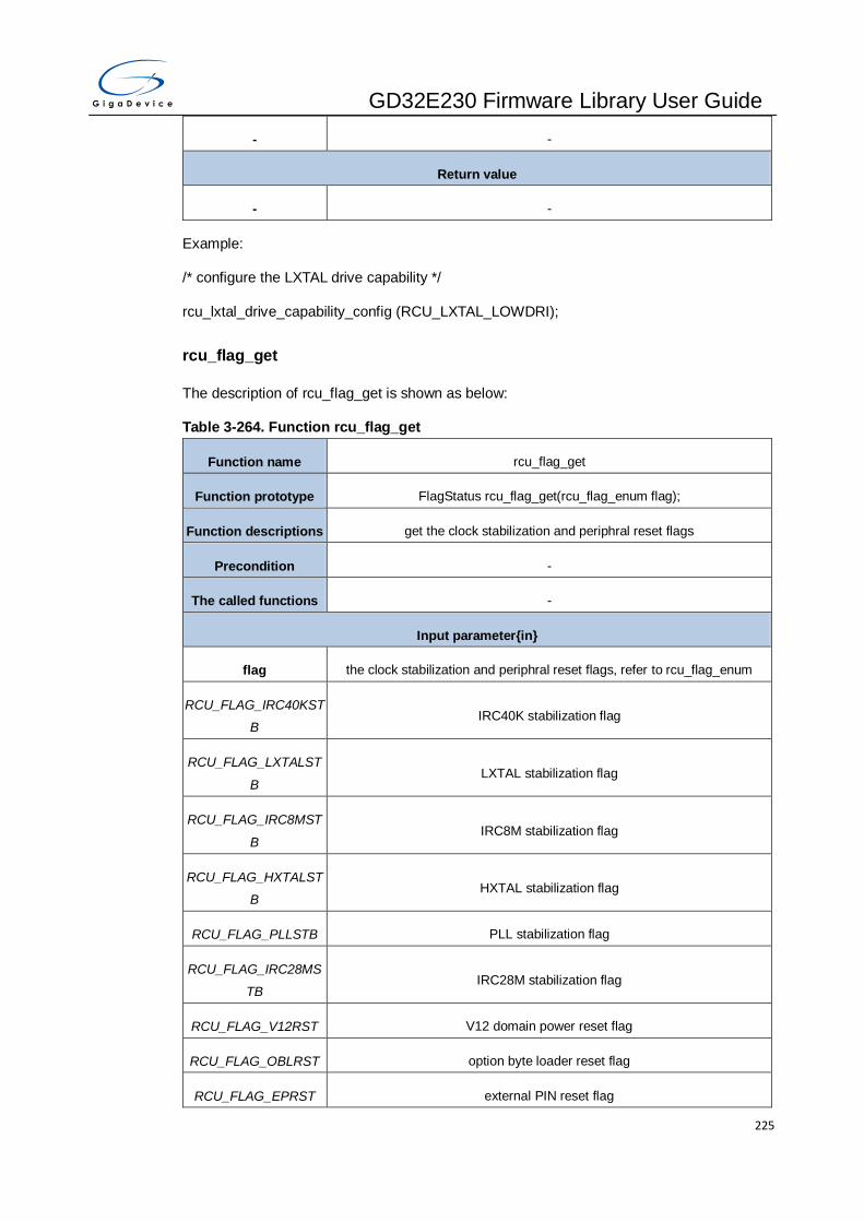
GD32E230 Firmware Library User Guide
225
- -
Return value
- -
Example:
/* configure the LXTAL drive capability */
rcu_lxtal_drive_capability_config (RCU_LXTAL_LOWDRI);
rcu_flag_get
The description of rcu_flag_get is shown as below:
Table 3-264. Function rcu_flag_get
Function name rcu_flag_get
Function prototype FlagStatus rcu_flag_get(rcu_flag_enum flag);
Function descriptions get the clock stabilization and periphral reset flags
Precondition -
The called functions -
Input parameter{in}
flag the clock stabilization and periphral reset flags, refer to rcu_flag_enum
RCU_FLAG_IRC40KST
B IRC40K stabilization flag
RCU_FLAG_LXTALST
B LXTAL stabilization flag
RCU_FLAG_IRC8MST
B IRC8M stabilization flag
RCU_FLAG_HXTALST
B HXTAL stabilization flag
RCU_FLAG_PLLSTB PLL stabilization flag
RCU_FLAG_IRC28MS
TB IRC28M stabilization flag
RCU_FLAG_V12RST V12 domain power reset flag
RCU_FLAG_OBLRST option byte loader reset flag
RCU_FLAG_EPRST external PIN reset flag

GD32E230 Firmware Library User Guide
226
RCU_FLAG_PORRST power reset flag
RCU_FLAG_SWRST software reset flag
RCU_FLAG_FWDGTR
ST free watchdog timer reset flag
RCU_FLAG_WWDGTR
ST window watchdog timer reset flag
RCU_FLAG_LPRST low-power reset flag
Output parameter{out}
- -
Return value
FlagStatus SET or RESET
Example:
/* get the clock stabilization flag */
if(RESET != rcu_flag_get(RCU_FLAG_LXTALSTB)){
}
rcu_all_reset_flag_clear
The description of rcu_all_reset_flag_clear is shown as below:
Table 3-265. Function rcu_all_reset_flag_clear
Function name rcu_all_reset_flag_clear
Function prototype void rcu_all_reset_flag_clear(void);
Function descriptions clear all the reset flag
Precondition -
The called functions -
Input parameter{in}
- -
Output parameter{out}
- -
Return value
- -
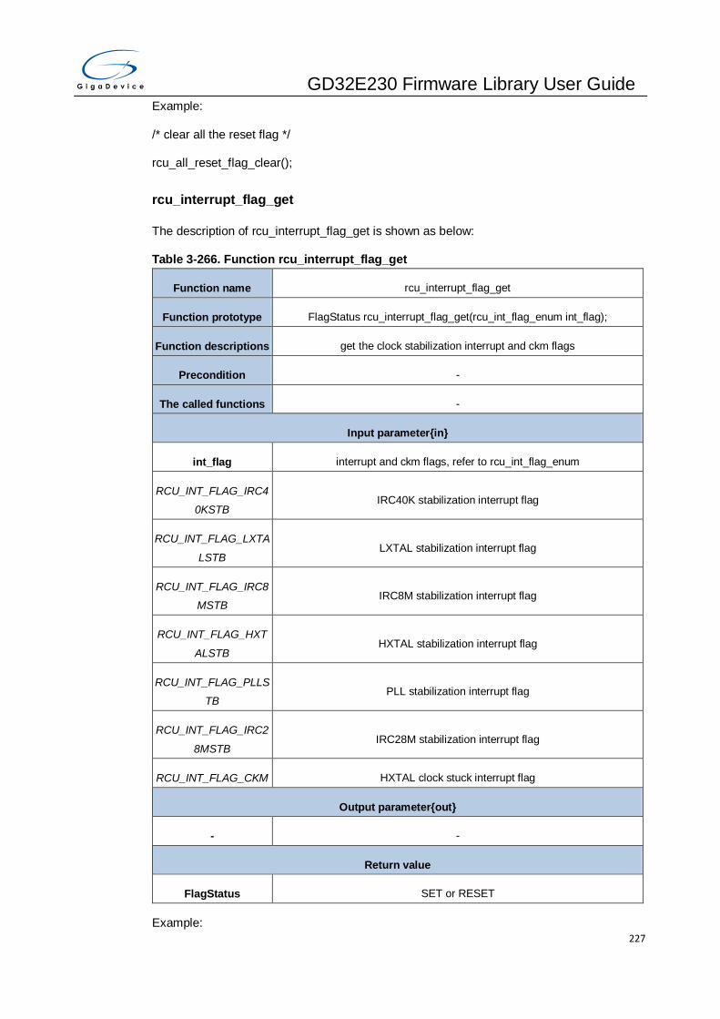
GD32E230 Firmware Library User Guide
227
Example:
/* clear all the reset flag */
rcu_all_reset_flag_clear();
rcu_interrupt_flag_get
The description of rcu_interrupt_flag_get is shown as below:
Table 3-266. Function rcu_interrupt_flag_get
Function name rcu_interrupt_flag_get
Function prototype FlagStatus rcu_interrupt_flag_get(rcu_int_flag_enum int_flag);
Function descriptions get the clock stabilization interrupt and ckm flags
Precondition -
The called functions -
Input parameter{in}
int_flag interrupt and ckm flags, refer to rcu_int_flag_enum
RCU_INT_FLAG_IRC4
0KSTB IRC40K stabilization interrupt flag
RCU_INT_FLAG_LXTA
LSTB LXTAL stabilization interrupt flag
RCU_INT_FLAG_IRC8
MSTB IRC8M stabilization interrupt flag
RCU_INT_FLAG_HXT
ALSTB HXTAL stabilization interrupt flag
RCU_INT_FLAG_PLLS
TB PLL stabilization interrupt flag
RCU_INT_FLAG_IRC2
8MSTB IRC28M stabilization interrupt flag
RCU_INT_FLAG_CKM HXTAL clock stuck interrupt flag
Output parameter{out}
- -
Return value
FlagStatus SET or RESET
Example:

GD32E230 Firmware Library User Guide
228
/* get the clock stabilization interrupt flag */
if(SET == rcu_interrupt_flag_get(RCU_INT_FLAG_HXTALSTB)){
}
rcu_interrupt_flag_clear
The description of rcu_interrupt_flag_clear is shown as below:
Table 3-267. Function rcu_interrupt_flag_clear
Function name rcu_interrupt_flag_clear
Function prototype void rcu_interrupt_flag_clear(rcu_int_flag_clear_enum int_flag_clear)
Function descriptions clear the interrupt flags
Precondition -
The called functions -
Input parameter{in}
int_flag_clear clock stabilization and stuck interrupt flags clear, refer to
rcu_int_flag_clear_enum
RCU_INT_FLAG_IRC4
0KSTB_CLR IRC40K stabilization interrupt flag clear
RCU_INT_FLAG_LXTA
LSTB_CLR LXTAL stabilization interrupt flag clear
RCU_INT_FLAG_IRC8
MSTB_CLR IRC8M stabilization interrupt flag clear
RCU_INT_FLAG_HXT
ALSTB_CLR HXTAL stabilization interrupt flag clear
RCU_INT_FLAG_PLLS
TB_CLR PLL stabilization interrupt flag clear
RCU_INT_FLAG_IRC2
8MSTB_CLR IRC28M stabilization interrupt flag clear
RCU_INT_FLAG_CKM
_CLR clock stuck interrupt flag clear
Output parameter{out}
- -
Return value

GD32E230 Firmware Library User Guide
229
- -
Example:
/* clear the interrupt HXTAL stabilization interrupt flag */
rcu_interrupt_flag_clear(RCU_INT_FLAG_HXTALSTB_CLR);
rcu_interrupt_enable
The description of rcu_interrupt_enable is shown as below:
Table 3-268. Function rcu_interrupt_enable
Function name rcu_interrupt_enable
Function prototype void rcu_interrupt_enable(rcu_int_enum stab_int);
Function descriptions enable the stabilization interrupt
Precondition -
The called functions -
Input parameter{in}
stab_int clock stabilization interrupt, refer to rcu_int_enum
RCU_INT_IRC40KSTB IRC40K stabilization interrupt enable
RCU_INT_LXTALSTB LXTAL stabilization interrupt enable
RCU_INT_IRC8MSTB IRC8M stabilization interrupt enable
RCU_INT_HXTALSTB HXTAL stabilization interrupt enable
RCU_INT_PLLSTB PLL stabilization interrupt enable
RCU_INT_IRC28MSTB IRC28M stabilization interrupt enable
Output parameter{out}
- -
Return value
- -
Example:
/* enable the HXTAL stabilization interrupt */
rcu_interrupt_enable(RCU_INT_HXTALSTB);

GD32E230 Firmware Library User Guide
230
rcu_interrupt_disable
The description of rcu_interrupt_disable is shown as below:
Table 3-269. Function rcu_interrupt_disable
Function name rcu_interrupt_disable
Function prototype void rcu_interrupt_disable(rcu_int_enum stab_int);
Function descriptions disable the stabilization interrupt
Precondition -
The called functions -
Input parameter{in}
stab_int clock stabilization interrupt, refer to rcu_int_enum
RCU_INT_IRC40KSTB IRC40K stabilization interrupt disable
RCU_INT_LXTALSTB LXTAL stabilization interrupt disable
RCU_INT_IRC8MSTB IRC8M stabilization interrupt disable
RCU_INT_HXTALSTB HXTAL stabilization interrupt disable
RCU_INT_PLLSTB PLL stabilization interrupt disable
RCU_INT_IRC28MSTB IRC28M stabilization interrupt disable
Output parameter{out}
- -
Return value
- -
Example:
/* disable the HXTAL stabilization interrupt */
rcu_interrupt_disable(RCU_INT_HXTALSTB);
rcu_osci_stab_wait
The description of rcu_osci_stab_wait is shown as below:
Table 3-270. Function rcu_osci_stab_wait
Function name rcu_osci_stab_wait
Function prototype ErrStatus rcu_osci_stab_wait(rcu_osci_type_enum osci);

GD32E230 Firmware Library User Guide
231
Function descriptions wait for oscillator stabilization flags is SET or oscillator startup is timeout
Precondition -
The called functions -
Input parameter{in}
osci oscillator types, refer to rcu_osci_type_enum
RCU_HXTAL high speed crystal oscillator(HXTAL)
RCU_LXTAL low speed crystal oscillator(LXTAL)
RCU_IRC8M internal 8M RC oscillators(IRC8M)
RCU_IRC28M internal 28M RC oscillators(IRC28M)
RCU_IRC40K internal 40K RC oscillator(IRC40K)
RCU_PLL_CK phase locked loop(PLL)
Output parameter{out}
- -
Return value
ErrStatus SUCCESS or ERROR
Example:
/* wait for oscillator stabilization flag */
if(SUCCESS == rcu_osci_stab_wait(RCU_HXTAL)){
}
rcu_osci_on
The description of rcu_osci_on is shown as below:
Table 3-271. Function rcu_osci_on
Function name rcu_osci_on
Function prototype void rcu_osci_on(rcu_osci_type_enum osci);
Function descriptions turn on the oscillator
Precondition -
The called functions -
Input parameter{in}
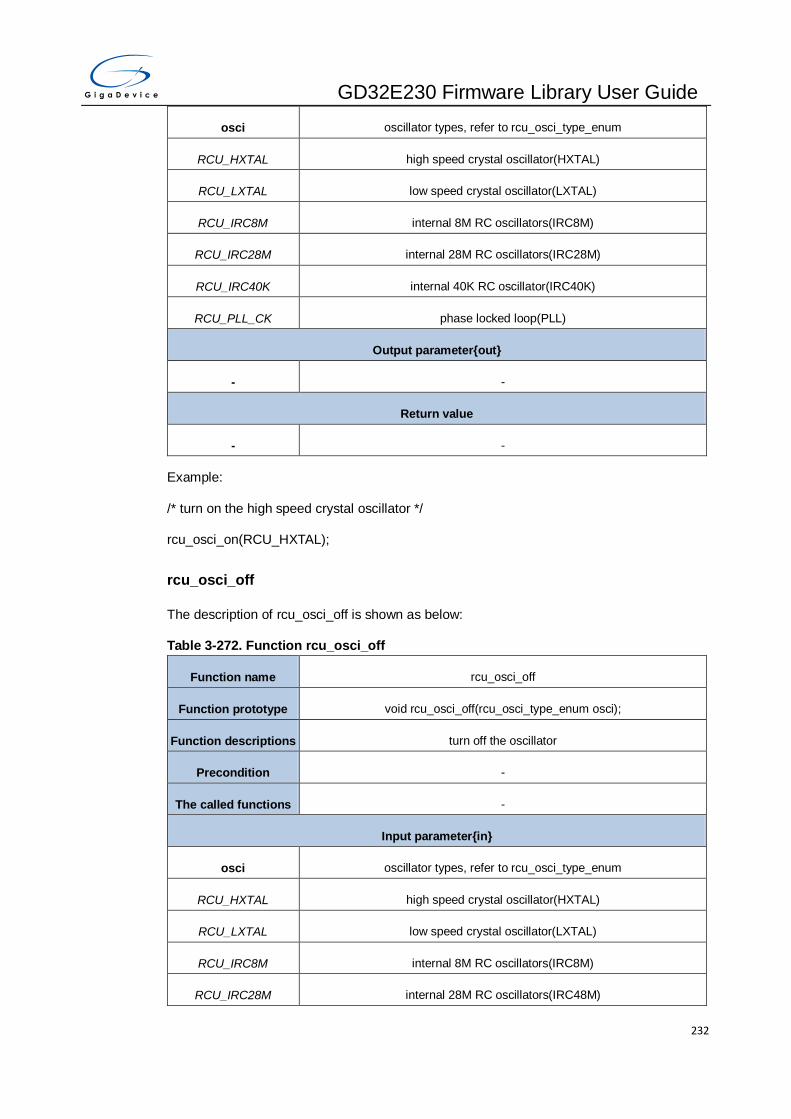
GD32E230 Firmware Library User Guide
232
osci oscillator types, refer to rcu_osci_type_enum
RCU_HXTAL high speed crystal oscillator(HXTAL)
RCU_LXTAL low speed crystal oscillator(LXTAL)
RCU_IRC8M internal 8M RC oscillators(IRC8M)
RCU_IRC28M internal 28M RC oscillators(IRC28M)
RCU_IRC40K internal 40K RC oscillator(IRC40K)
RCU_PLL_CK phase locked loop(PLL)
Output parameter{out}
- -
Return value
- -
Example:
/* turn on the high speed crystal oscillator */
rcu_osci_on(RCU_HXTAL);
rcu_osci_off
The description of rcu_osci_off is shown as below:
Table 3-272. Function rcu_osci_off
Function name rcu_osci_off
Function prototype void rcu_osci_off(rcu_osci_type_enum osci);
Function descriptions turn off the oscillator
Precondition -
The called functions -
Input parameter{in}
osci oscillator types, refer to rcu_osci_type_enum
RCU_HXTAL high speed crystal oscillator(HXTAL)
RCU_LXTAL low speed crystal oscillator(LXTAL)
RCU_IRC8M internal 8M RC oscillators(IRC8M)
RCU_IRC28M internal 28M RC oscillators(IRC48M)

GD32E230 Firmware Library User Guide
233
RCU_IRC40K internal 40K RC oscillator(IRC40K)
RCU_PLL_CK phase locked loop(PLL)
Output parameter{out}
- -
Return value
- -
Example:
/* turn off the high speed crystal oscillator */
rcu_osci_off(RCU_HXTAL);
rcu_osci_bypass_mode_enable
The description of rcu_osci_bypass_mode_enable is shown as below:
Table 3-273. Function rcu_osci_bypass_mode_enable
Function name rcu_osci_bypass_mode_enable
Function prototype void rcu_osci_bypass_mode_enable(rcu_osci_type_enum osci);
Function descriptions enable the oscillator bypass mode
Precondition HXTALEN or LXTALEN must be reset before it
The called functions -
Input parameter{in}
osci oscillator types, refer to rcu_osci_type_enum
RCU_HXTAL high speed crystal oscillator(HXTAL)
RCU_LXTAL low speed crystal oscillator(LXTAL)
Output parameter{out}
- -
Return value
- -
Example:
/* enable the high speed crystal oscillator bypass mode */
rcu_osci_bypass_mode_enable(RCU_HXTAL);

GD32E230 Firmware Library User Guide
234
rcu_osci_bypass_mode_disable
The description of rcu_osci_bypass_mode_disable is shown as below:
Table 3-274. Function rcu_osci_bypass_mode_disable
Function name rcu_osci_bypass_mode_disable
Function prototype void rcu_osci_bypass_mode_disable(rcu_osci_type_enum osci);
Function descriptions disable the oscillator bypass mode
Precondition HXTALEN or LXTALEN must be reset before it
The called functions -
Input parameter{in}
osci oscillator types, refer to rcu_osci_type_enum
RCU_HXTAL high speed crystal oscillator(HXTAL)
RCU_LXTAL low speed crystal oscillator(LXTAL)
Output parameter{out}
- -
Return value
- -
Example:
/* disable the high speed crystal oscillator bypass mode */
rcu_osci_bypass_mode_disable(RCU_HXTAL);
rcu_hxtal_clock_monitor_enable
The description of rcu_hxtal_clock_monitor_enable is shown as below:
Table 3-275. Function rcu_hxtal_clock_monitor_enable
Function name rcu_hxtal_clock_monitor_enable
Function prototype void rcu_hxtal_clock_monitor_enable(void);
Function descriptions enable the HXTAL clock monitor
Precondition -
The called functions -
Input parameter{in}

GD32E230 Firmware Library User Guide
235
- -
Output parameter{out}
- -
Return value
- -
Example:
/* enable the HXTAL clock monitor */
rcu_hxtal_clock_monitor_enable();
rcu_hxtal_clock_monitor_disable
The description of rcu_hxtal_clock_monitor_disable is shown as below:
Table 3-276. Function rcu_hxtal_clock_monitor_disable
Function name rcu_hxtal_clock_monitor_disable
Function prototype void rcu_hxtal_clock_monitor_disable(void);
Function descriptions disable the HXTAL clock monitor
Precondition -
The called functions -
Input parameter{in}
- -
Output parameter{out}
- -
Return value
- -
Example:
/* disable the HXTAL clock monitor */
rcu_hxtal_clock_monitor_disable();
rcu_irc8m_adjust_value_set
The description of rcu_irc8m_adjust_value_set is shown as below:

GD32E230 Firmware Library User Guide
236
Table 3-277. Function rcu_irc8m_adjust_value_set
Function name rcu_irc8m_adjust_value_set
Function prototype void rcu_irc8m_adjust_value_set(uint32_t irc8m_adjval);
Function descriptions set the IRC8M adjust value
Precondition -
The called functions -
Input parameter{in}
irc8m_adjval IRC8M adjust value, must be between 0 and 0x1F
Output parameter{out}
- -
Return value
- -
Example:
/* set the IRC8M adjust value */
rcu_irc8m_adjust_value_set(0x10);
rcu_irc28m_adjust_value_set
The description of rcu_irc28m_adjust_value_set is shown as below:
Table 3-278. Function rcu_irc28m_adjust_value_set
Function name rcu_irc28m_adjust_value_set
Function prototype void rcu_irc28m_adjust_value_set(uint32_t irc28m_adjval);
Function descriptions set the IRC28M adjust value
Precondition -
The called functions -
Input parameter{in}
irc28m_adjval IRC28M adjust value, must be between 0 and 0x1F
Output parameter{out}
- -
Return value

GD32E230 Firmware Library User Guide
237
- -
Example:
/* set the IRC28M adjust value */
rcu_irc28m_adjust_value_set(0x10);
rcu_voltage_key_unlock
The description of rcu_voltage_key_unlock is shown as below:
Table 3-279. Function rcu_voltage_key_unlock
Function name rcu_voltage_key_unlock
Function prototype void rcu_voltage_key_unlock (void);
Function descriptions unlock the voltage key
Precondition -
The called functions -
Input parameter{in}
- -
Output parameter{out}
- -
Return value
- -
Example:
/* unlock the voltage key */
rcu_voltage_key_unlock();
rcu_deepsleep_voltage_set
The description of rcu_deepsleep_voltage_set is shown as below:
Table 3-280. Function rcu_deepsleep_voltage_set
Function name rcu_deepsleep_voltage_set
Function prototype void rcu_deepsleep_voltage_set(uint32_t dsvol);
Function descriptions set voltage in deep sleep mode
Precondition -

GD32E230 Firmware Library User Guide
238
The called functions -
Input parameter{in}
dsvol deep sleep mode voltage
RCU_DEEPSLEEP_V_
1_0 the core voltage is 1.0V in deep-sleep mode
RCU_DEEPSLEEP_V_
0_9
the core voltage is 0.9V in deep-sleep mode
RCU_DEEPSLEEP_V_
0_8
the core voltage is 0.8V in deep-sleep mode
RCU_DEEPSLEEP_V_
1_2
the core voltage is 1.2V in deep-sleep mode
Output parameter{out}
- -
Return value
- -
Example:
/* set the deep-sleep mode voltage */
rcu_deepsleep_voltage_set(RCU_DEEPSLEEP_V_1_0);
rcu_clock_freq_get
The description of rcu_clock_freq_get is shown as below:
Table 3-281. Function rcu_clock_freq_get
Function name rcu_clock_freq_get
Function prototype uint32_t rcu_clock_freq_get(rcu_clock_freq_enum clock);
Function descriptions get the system clock, bus clock and peripheral clock frequency
Precondition -
The called functions -
Input parameter{in}
clock the clock frequency which to get
CK_SYS system clock frequency

GD32E230 Firmware Library User Guide
239
CK_AHB AHB clock frequency
CK_APB1 APB1 clock frequency
CK_APB2 APB2 clock frequency
CK_ADC ADC clock frequency
CK_USART USART0 clock frequency
Output parameter{out}
- -
Return value
uint32_t clock frequency of system, AHB, APB1, APB2,ADC or USART0
Example:
uint32_t temp_freq;
/* get the system clock frequency */
temp_freq = rcu_clock_freq_get(CK_SYS);
3.15. RTC
The Real-time Clock (RTC) is usually used as a clock-calendar. The ones in the Backup
Domain consist of a 32-bit up-counter, an alarm, a prescaler, a divider and the RTC clock
configuration register. The RTC registers are listed in chapter 3.15.1, the FWDGT firmware
functions are introduced in chapter 3.15.2.
3.15.1. Descriptions of Peripheral registers
RTC registers are listed in the table shown as below:
Table 3-282. RTC Registers
Registers Descriptions
RTC_TIME RTC time of day register
RTC_DATE RTC date register
RTC_CTL RTC control register
RTC_STAT RTC status register
RTC_PSC RTC time prescaler register
RTC_ALRM0TD RTC alarm 0 time and date register
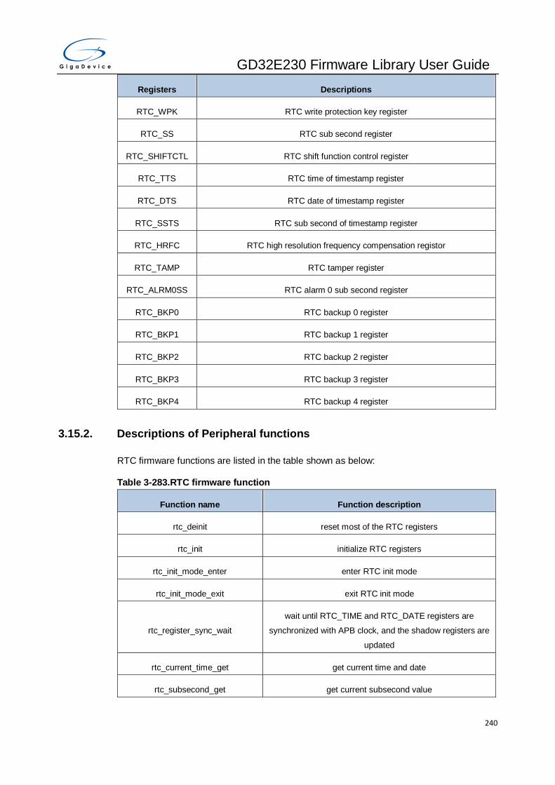
GD32E230 Firmware Library User Guide
240
Registers Descriptions
RTC_WPK RTC write protection key register
RTC_SS RTC sub second register
RTC_SHIFTCTL RTC shift function control register
RTC_TTS RTC time of timestamp register
RTC_DTS RTC date of timestamp register
RTC_SSTS RTC sub second of timestamp register
RTC_HRFC RTC high resolution frequency compensation registor
RTC_TAMP RTC tamper register
RTC_ALRM0SS RTC alarm 0 sub second register
RTC_BKP0 RTC backup 0 register
RTC_BKP1 RTC backup 1 register
RTC_BKP2 RTC backup 2 register
RTC_BKP3 RTC backup 3 register
RTC_BKP4 RTC backup 4 register
3.15.2. Descriptions of Peripheral functions
RTC firmware functions are listed in the table shown as below:
Table 3-283.RTC firmware function
Function name Function description
rtc_deinit reset most of the RTC registers
rtc_init initialize RTC registers
rtc_init_mode_enter enter RTC init mode
rtc_init_mode_exit exit RTC init mode
rtc_register_sync_wait
wait until RTC_TIME and RTC_DATE registers are
synchronized with APB clock, and the shadow registers are
updated
rtc_current_time_get get current time and date
rtc_subsecond_get get current subsecond value

GD32E230 Firmware Library User Guide
241
Function name Function description
rtc_alarm_config configure RTC alarm
rtc_alarm_subsecond_config configure subsecond of RTC alarm
rtc_alarm_get get RTC alarm
rtc_alarm_subsecond_get get RTC alarm subsecond
rtc_alarm_enable enable RTC alarm
rtc_alarm_disable disable RTC alarm
rtc_timestamp_enable enable RTC time-stamp
rtc_timestamp_disable disable RTC time-stamp
rtc_timestamp_get get RTC timestamp time and date
rtc_timestamp_subsecond_get get RTC time-stamp subsecond
rtc_tamper_enable enable RTC tamper
rtc_tamper_disable disable RTC tamper
rtc_interrupt_enable enable specified RTC interrupt
rtc_interrupt_disable disble specified RTC interrupt
rtc_flag_get check specified flag
rtc_flag_clear clear specified flag
rtc_alter_output_config configure RTC alternate output source
rtc_calibration_config configure RTC calibration register
rtc_hour_adjust ajust the daylight saving time by adding or substracting one
hour from the current time
rtc_second_adjust ajust RTC second or subsecond value of current time
rtc_bypass_shadow_enable enable RTC bypass shadow registers function
rtc_bypass_shadow_disable disable RTC bypass shadow registers function
rtc_refclock_detection_enable enable RTC reference clock detection function
rtc_refclock_detection_disable disable RTC reference clock detection function

GD32E230 Firmware Library User Guide
242
Structure rtc_parameter_struct
Table 3-284. rtc_parameter_struct
Member name Function description
rtc_year RTC year value: 0x0 - 0x99(BCD format)
rtc_month RTC month value
rtc_date RTC date value: 0x1 - 0x31(BCD format)
rtc_day_of_week RTC weekday value
rtc_hour RTC hour value
rtc_minute RTC minute value: 0x0 - 0x59(BCD format)
rtc_second RTC second value: 0x0 - 0x59(BCD format)
rtc_factor_asyn RTC asynchronous prescaler value: 0x0 - 0x7F
rtc_factor_syn RTC synchronous prescaler value: 0x0 - 0x7FFF
rtc_am_pm RTC AM/PM value
rtc_display_format RTC time notation
Structure rtc_alarm_struct
Table 3-285. rtc_alarm_struct
Member name Function description
rtc_alarm_mask RTC alarm mask
rtc_weekday_or_dat
e specify RTC alarm is on date or weekday
rtc_alarm_day RTC alarm date or weekday value
rtc_alarm_hour RTC alarm hour value
rtc_alarm_minute RTC alarm minute value: 0x0 - 0x59(BCD format)
rtc_alarm_second RTC alarm second value: 0x0 - 0x59(BCD format)
rtc_am_pm RTC alarm AM/PM value
Structure rtc_timestamp_struct
Table 3-286. rtc_timestamp_struct
Member name Function description

GD32E230 Firmware Library User Guide
243
rtc_timestamp_mont
h RTC time-stamp month value
rtc_timestamp_date RTC time-stamp date value: 0x1 - 0x31(BCD format)
rtc_timestamp_day RTC time-stamp weekday value
rtc_timestamp_hour RTC time-stamp hour value
rtc_timestamp_minu
te RTC time-stamp minute value: 0x0 - 0x59(BCD format)
rtc_timestamp_seco
nd RTC time-stamp second value: 0x0 - 0x59(BCD format)
rtc_am_pm RTC time-stamp AM/PM value
Structure rtc_tamper_struct
Table 3-287. rtc_tamper_struct
Member name Function description
rtc_tamper_source RTC tamper source
rtc_tamper_trigger RTC tamper trigger
rtc_tamper_filter RTC tamper consecutive samples needed during a voltage level detection
rtc_tamper_sample_
frequency RTC tamper sampling frequency during a voltage level detection
rtc_tamper_prechar
ge_enable RTC tamper precharge feature during a voltage level detection
rtc_tamper_prechar
ge_time RTC tamper precharge duration if precharge feature is enabled
rtc_tamper_with_tim
estamp RTC tamper time-stamp feature
rtc_deinit
The description of rtc_deinit is shown as below:
Table 3-288. Function rtc_deinit
Function name rtc_deinit
Function prototype ErrStatus rtc_deinit(void);
Function descriptions reset most of the RTC registers

GD32E230 Firmware Library User Guide
244
Precondition -
The called functions rcu_periph_reset_enable/ rcu_periph_reset_disable -
Input parameter{in}
- -
Output parameter{out}
- -
Return value
ErrStatus ERROR or SUCCESS
Example:
/* reset most of the RTC registers*/
ErrStatus error_status = rtc_deinit();
rtc_init
The description of rtc_init is shown as below:
Table 3-289. Function rtc_init
Function name rtc_init
Function prototype ErrStatus rtc_init(rtc_parameter_struct* rtc_initpara_struct);
Function descriptions initialize RTC registers
Precondition -
The called functions -
Input parameter{in}
rtc_initpara_struct
pointer to a rtc_parameter_struct structure which contains
parameters for initialization of the rtc peripheral, the structure members can
refer to members of the structure Table 3-284. rtc_parameter_struct
Output parameter{out}
- -
Return value
ErrStatus ERROR or SUCCESS
Example:
/* reset most of the RTC registers*/

GD32E230 Firmware Library User Guide
245
ErrStatus error_status = rtc_init ();
rtc_init_mode_enter
The description of rtc_init_mode_enter is shown as below:
Table 3-290. Function rtc_init_mode_enter
Function name rtc_init_mode_enter
Function prototype ErrStatus rtc_init_mode_enter(void);
Function descriptions enter RTC init mode
Precondition -
The called functions -
Input parameter{in}
- -
Output parameter{out}
- -
Return value
ErrStatus ERROR or SUCCESS
Example:
/*enter RTC init mode*/
ErrStatus error_status = rtc_init_mode_enter ();
rtc_init_mode_exit
The description of rtc_init_mode_exit is shown as below:
Table 3-291. Function rtc_init_mode_exit
Function name rtc_init_mode_exit
Function prototype void rtc_init_mode_exit(void);
Function descriptions exit RTC init mode
Precondition -
The called functions -
Input parameter{in}
- -

GD32E230 Firmware Library User Guide
246
Output parameter{out}
- -
Return value
- -
Example:
/*exit RTC init mode*/
rtc_init_mode_exit ();
rtc_register_sync_wait
The description of rtc_register_sync_wait is shown as below:
Table 3-292. Function rtc_register_sync_wait
Function name rtc_register_sync_wait
Function prototype ErrStatus rtc_register_sync_wait(void);
Function descriptions wait until RTC_TIME and RTC_DATE registers are synchronized with APB
clock, and the shadow registers are updated
Precondition -
The called functions -
Input parameter{in}
- -
Output parameter{out}
- -
Return value
ErrStatus ERROR or SUCCESS
Example:
/*wait until RTC_TIME and RTC_DATE registers are synchronized with APB clock, and the
shadow registers are updated*/
ErrStatus error_status = rtc_register_sync_wait ();
rtc_current_time_get
The description of rtc_current_time_get is shown as below:

GD32E230 Firmware Library User Guide
247
Table 3-293. Function rtc_current_time_get
Function name rtc_current_time_get
Function prototype void rtc_current_time_get(rtc_parameter_struct* rtc_initpara_struct);
Function descriptions get current time and date
Precondition -
The called functions -
Input parameter{in}
- -
Output parameter{out}
rtc_initpara_struct
pointer to a rtc_parameter_struct structure which contains
parameters for initialization of the rtc peripheral, the structure members can
refer to members of the structure Table 3-284. rtc_parameter_struct
Return value
- -
Example:
/*get current time and date*/
rtc_parameter_struct rtc_initpara_struct;
rtc_current_time_get (&rtc_initpara_struct);
rtc_subsecond_get
The description of rtc_subsecond_get is shown as below:
Table 3-294. Function rtc_subsecond_get
Function name rtc_subsecond_get
Function prototype uint32_t rtc_subsecond_get(void);
Function descriptions get current subsecond value
Precondition -
The called functions -
Input parameter{in}
- -
Output parameter{out}

GD32E230 Firmware Library User Guide
248
- -
Return value
uint32_t current subsecond value(0x00-0xFFFF)
Example:
/*get current subsecond value*/
uint32_t sub_second = rtc_subsecond_get();
rtc_alarm_config
The description of rtc_alarm_config is shown as below:
Table 3-295. Function rtc_alarm_config
Function name rtc_alarm_config
Function prototype void rtc_alarm_config(rtc_alarm_struct* rtc_alarm_time)
Function descriptions configure RTC alarm
Precondition -
The called functions -
Input parameter{in}
rtc_alarm_time
pointer to a rtc_alarm_struct structure which contains
parameters for RTC alarm configuration, the structure members can refer to
members of the structure Table 3-285. rtc_alarm_struct
Output parameter{out}
- -
Return value
- -
Example:
/*rtc_alarm_config*/
rtc_alarm_struct rtc_alarm_time;
rtc_alarm_config(&rtc_alarm_time);
rtc_alarm_subsecond_config
The description of rtc_alarm_subsecond_config is shown as below:

GD32E230 Firmware Library User Guide
249
Table 3-296. Function rtc_alarm_subsecond_config
Function name rtc_alarm_subsecond_config
Function prototype void rtc_alarm_subsecond_config(uint32_t mask_subsecond, uint32_t
subsecond);
Function descriptions configure subsecond of RTC alarm
Precondition -
The called functions -
Input parameter{in}
mask_subsecond alarm subsecond mask
RTC_MASKSSC_0_14 mask alarm subsecond configuration
RTC_MASKSSC_1_14 mask RTC_ALRM0SS_SSC[14:1], and RTC_ALRM0SS_SSC[0] is to be
compared
RTC_MASKSSC_2_14 mask RTC_ALRM0SS_SSC[14:2], and RTC_ALRM0SS_SSC[1:0] is to be
compared
RTC_MASKSSC_3_14 mask RTC_ALRM0SS_SSC[14:3], and RTC_ALRM0SS_SSC[2:0] is to be
compared
RTC_MASKSSC_4_14 mask RTC_ALRM0SS_SSC[14:4], and RTC_ALRM0SS_SSC[3:0] is to be
compared
RTC_MASKSSC_5_14 mask RTC_ALRM0SS_SSC[14:5], and RTC_ALRM0SS_SSC[4:0] is to be
compared
RTC_MASKSSC_6_14 mask RTC_ALRM0SS_SSC[14:6], and RTC_ALRM0SS_SSC[5:0] is to be
compared
RTC_MASKSSC_7_14 mask RTC_ALRM0SS_SSC[14:7], and RTC_ALRM0SS_SSC[6:0] is to be
compared
RTC_MASKSSC_8_14 mask RTC_ALRM0SS_SSC[14:8], and RTC_ALRM0SS_SSC[7:0] is to be
compared
RTC_MASKSSC_9_14 mask RTC_ALRM0SS_SSC[14:9], and RTC_ALRM0SS_SSC[8:0] is to be
compared
RTC_MASKSSC_10_1
4
mask RTC_ALRM0SS_SSC[14:10], and RTC_ALRM0SS_SSC[9:0] is to be
compared
RTC_MASKSSC_11_1
4
mask RTC_ALRM0SS_SSC[14:11], and RTC_ALRM0SS_SSC[10:0] is to
be compared
RTC_MASKSSC_12_1 mask RTC_ALRM0SS_SSC[14:12], and RTC_ALRM0SS_SSC[11:0] is to
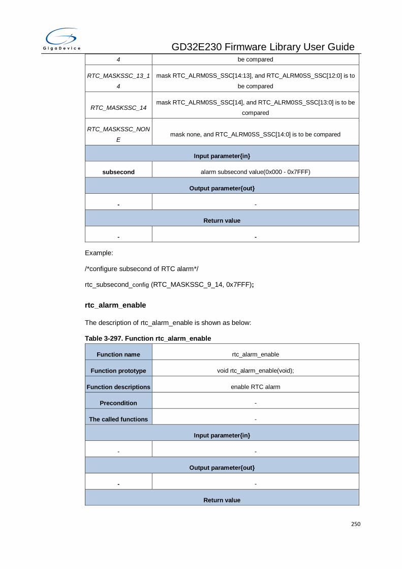
GD32E230 Firmware Library User Guide
250
4 be compared
RTC_MASKSSC_13_1
4
mask RTC_ALRM0SS_SSC[14:13], and RTC_ALRM0SS_SSC[12:0] is to
be compared
RTC_MASKSSC_14 mask RTC_ALRM0SS_SSC[14], and RTC_ALRM0SS_SSC[13:0] is to be
compared
RTC_MASKSSC_NON
E mask none, and RTC_ALRM0SS_SSC[14:0] is to be compared
Input parameter{in}
subsecond alarm subsecond value(0x000 - 0x7FFF)
Output parameter{out}
- -
Return value
- -
Example:
/*configure subsecond of RTC alarm*/
rtc_subsecond_config (RTC_MASKSSC_9_14, 0x7FFF);
rtc_alarm_enable
The description of rtc_alarm_enable is shown as below:
Table 3-297. Function rtc_alarm_enable
Function name rtc_alarm_enable
Function prototype void rtc_alarm_enable(void);
Function descriptions enable RTC alarm
Precondition -
The called functions -
Input parameter{in}
- -
Output parameter{out}
- -
Return value

GD32E230 Firmware Library User Guide
251
- -
Example:
/*enable RTC alarm*/
rtc_alarm_enable();
rtc_alarm_disable
The description of rtc_alarm_disable is shown as below:
Table 3-298. Function rtc_alarm_disable
Function name rtc_alarm_disable
Function prototype ErrStatus rtc_alarm_disable(void);
Function descriptions disable RTC alarm
Precondition -
The called functions -
Input parameter{in}
- -
Output parameter{out}
- -
Return value
ErrStatus ERROR or SUCCESS
Example:
/*disable RTC alarm*/
ErrStatus error_status = rtc_alarm_disable();
rtc_alarm_get
The description of rtc_alarm_get is shown as below:
Table 3-299. Function rtc_alarm_get
Function name rtc_alarm_get
Function prototype void rtc_alarm_get(rtc_alarm_struct* rtc_alarm_time);
Function descriptions get RTC alarm
Precondition -
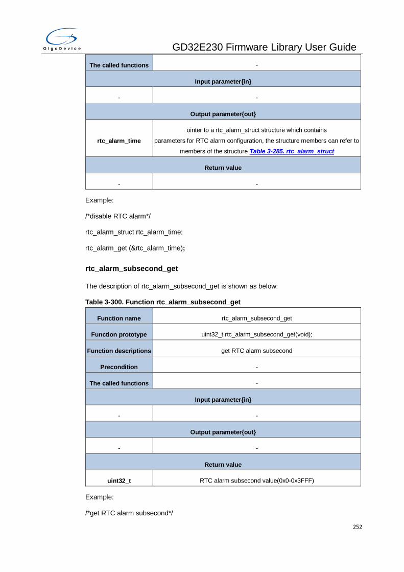
GD32E230 Firmware Library User Guide
252
The called functions -
Input parameter{in}
- -
Output parameter{out}
rtc_alarm_time
ointer to a rtc_alarm_struct structure which contains
parameters for RTC alarm configuration, the structure members can refer to
members of the structure Table 3-285. rtc_alarm_struct
Return value
- -
Example:
/*disable RTC alarm*/
rtc_alarm_struct rtc_alarm_time;
rtc_alarm_get (&rtc_alarm_time);
rtc_alarm_subsecond_get
The description of rtc_alarm_subsecond_get is shown as below:
Table 3-300. Function rtc_alarm_subsecond_get
Function name rtc_alarm_subsecond_get
Function prototype uint32_t rtc_alarm_subsecond_get(void);
Function descriptions get RTC alarm subsecond
Precondition -
The called functions -
Input parameter{in}
- -
Output parameter{out}
- -
Return value
uint32_t RTC alarm subsecond value(0x0-0x3FFF)
Example:
/*get RTC alarm subsecond*/

GD32E230 Firmware Library User Guide
253
uint32_t subsecond = rtc_alarm_subsecond_get();
rtc_timestamp_enable
The description of rtc_timestamp_enable is shown as below:
Table 3-301. Function rtc_timestamp_enable
Function name rtc_timestamp_enable
Function prototype void rtc_timestamp_enable(uint32_t edge);
Function descriptions enable RTC time-stamp
Precondition -
The called functions -
Input parameter{in}
edge specify which edge to detect of time-stamp
RTC_TIMESTAMP_RIS
ING_EDGE rising edge is valid event edge for timestamp event
RTC_TIMESTAMP_FA
LLING_EDGE falling edge is valid event edge for timestamp event
Output parameter{out}
- -
Return value
- -
Example:
/*enable RTC time-stamp*/
rtc_timestamp_enable (RTC_TIMESTAMP_RISING_EDGE);
rtc_timestamp_disable
The description of rtc_timestamp_disable is shown as below:
Table 3-302. Function rtc_timestamp_disable
Function name rtc_timestamp_disable
Function prototype void rtc_timestamp_disable(void);
Function descriptions disable RTC time-stamp
Precondition -

GD32E230 Firmware Library User Guide
254
The called functions -
Input parameter{in}
- -
Output parameter{out}
- -
Return value
- -
Example:
/*disable RTC time-stamp*/
rtc_timestamp_disable ();
rtc_timestamp_get
The description of rtc_timestamp_get is shown as below:
Table 3-303. Function rtc_timestamp_get
Function name rtc_timestamp_get
Function prototype void rtc_timestamp_get(rtc_timestamp_struct* rtc_timestamp);
Function descriptions get RTC timestamp time and date
Precondition -
The called functions -
Input parameter{in}
- -
Output parameter{out}
rtc_timestamp
Pointer to a rtc_timestamp_struct structure which contains
parameters for RTC time-stamp configuration,the structure members can
refer to members of the structure Table 3-287. rtc_tamper_struct
Return value
- -
Example:
/* get RTC timestamp time and date */
rtc_timestamp_struct rtc_timestamp;

GD32E230 Firmware Library User Guide
255
rtc_timestamp_get(& rtc_timestamp);
rtc_timestamp_subsecond_get
The description of rtc_timestamp_subsecond_get is shown as below:
Table 3-304. Function rtc_timestamp_subsecond_get
Function name rtc_timestamp_subsecond_get
Function prototype uint32_t rtc_timestamp_subsecond_get(void);
Function descriptions get RTC time-stamp subsecond
Precondition -
The called functions -
Input parameter{in}
- -
Output parameter{out}
- -
Return value
uint32_t RTC time-stamp subsecond value
Example:
/* get RTC time-stamp subsecond */
uint32_t subsecond = rtc_timestamp_subsecond_get();
rtc_tamper_enable
The description of rtc_tamper_enable is shown as below:
Table 3-305. Function rtc_timestamp_enable
Function name rtc_tamper_enable
Function prototype void rtc_tamper_enable(rtc_tamper_struct* rtc_tamper);
Function descriptions enable RTC tamper
Precondition -
The called functions -
Input parameter{in}
rtc_tamper pointer to a rtc_tamper_struct structure which contains

GD32E230 Firmware Library User Guide
256
parameters for RTC tamper configuration, the structure members can refer
to members of the structure Table 3-287. rtc_tamper_struct
Output parameter{out}
- -
Return value
- -
Example:
/* enable RTC tamper */
rtc_tamper_struct rtc_tamper
rtc_tamper_enable(& rtc_tamper);
rtc_tamper_disable
The description of rtc_tamper_disable is shown as below:
Table 3-306. Function rtc_tamper_disable
Function name rtc_tamper_disable
Function prototype void rtc_tamper_disable(uint32_t source);
Function descriptions disable RTC tamper
Precondition -
The called functions -
Input parameter{in}
source specify which tamper source to be disabled
RTC_TAMPER0 RTC tamper0
RTC_TAMPER1 RTC tamper1
Output parameter{out}
- -
Return value
- -
Example:
/* disable RTC tamper */
rtc_tamper_disable(RTC_TAMPER0);
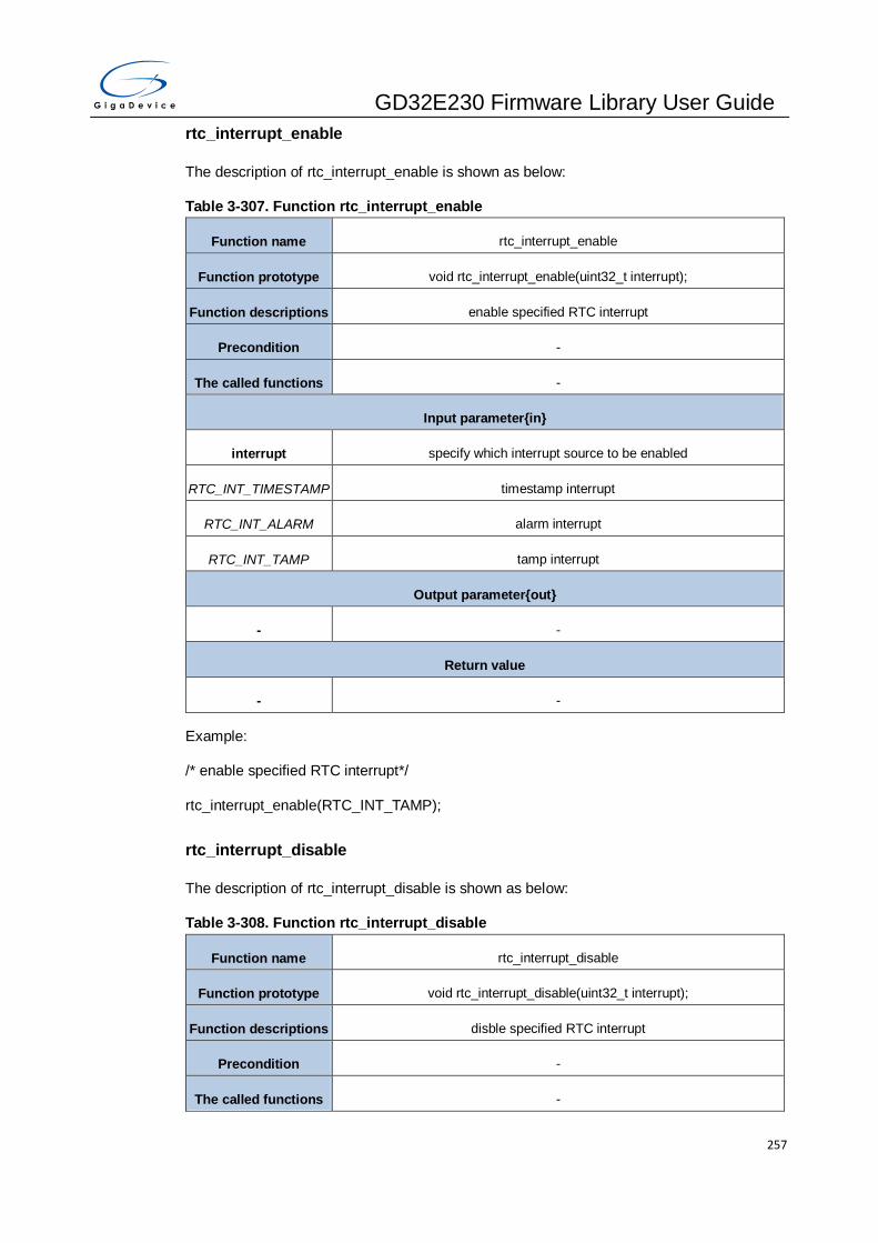
GD32E230 Firmware Library User Guide
257
rtc_interrupt_enable
The description of rtc_interrupt_enable is shown as below:
Table 3-307. Function rtc_interrupt_enable
Function name rtc_interrupt_enable
Function prototype void rtc_interrupt_enable(uint32_t interrupt);
Function descriptions enable specified RTC interrupt
Precondition -
The called functions -
Input parameter{in}
interrupt specify which interrupt source to be enabled
RTC_INT_TIMESTAMP timestamp interrupt
RTC_INT_ALARM alarm interrupt
RTC_INT_TAMP tamp interrupt
Output parameter{out}
- -
Return value
- -
Example:
/* enable specified RTC interrupt*/
rtc_interrupt_enable(RTC_INT_TAMP);
rtc_interrupt_disable
The description of rtc_interrupt_disable is shown as below:
Table 3-308. Function rtc_interrupt_disable
Function name rtc_interrupt_disable
Function prototype void rtc_interrupt_disable(uint32_t interrupt);
Function descriptions disble specified RTC interrupt
Precondition -
The called functions -
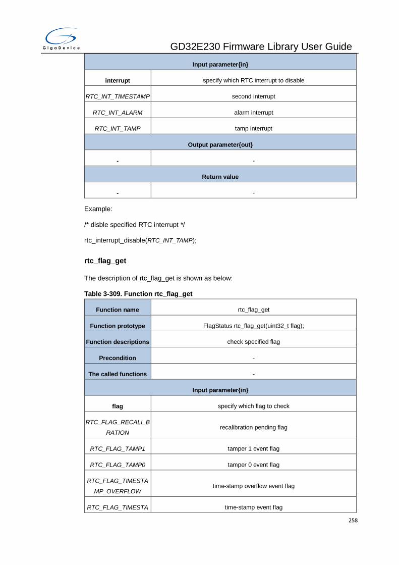
GD32E230 Firmware Library User Guide
258
Input parameter{in}
interrupt specify which RTC interrupt to disable
RTC_INT_TIMESTAMP second interrupt
RTC_INT_ALARM alarm interrupt
RTC_INT_TAMP tamp interrupt
Output parameter{out}
- -
Return value
- -
Example:
/* disble specified RTC interrupt */
rtc_interrupt_disable(RTC_INT_TAMP);
rtc_flag_get
The description of rtc_flag_get is shown as below:
Table 3-309. Function rtc_flag_get
Function name rtc_flag_get
Function prototype FlagStatus rtc_flag_get(uint32_t flag);
Function descriptions check specified flag
Precondition -
The called functions -
Input parameter{in}
flag specify which flag to check
RTC_FLAG_RECALI_B
RATION recalibration pending flag
RTC_FLAG_TAMP1 tamper 1 event flag
RTC_FLAG_TAMP0 tamper 0 event flag
RTC_FLAG_TIMESTA
MP_OVERFLOW time-stamp overflow event flag
RTC_FLAG_TIMESTA time-stamp event flag

GD32E230 Firmware Library User Guide
259
MP
RTC_FLAG_ALARM0 alarm event flag
RTC_FLAG_INIT init mode event flag
RTC_FLAG_RSYN time and date registers synchronized event flag
RTC_FLAG_YCM year parameter configured event flag
RTC_FLAG_SHIFT shift operation pending flag
RTC_FLAG_ALARM0_
WRITTEN alarm writen available flag
Output parameter{out}
- -
Return value
FlagStatus SET or RESET
Example:
/* check time-stamp event flag */
FlagStatus = rtc_flag_get(RTC_FLAG_TIMESTAMP)
rtc_flag_clear
The description of rtc_flag_clear is shown as below:
Table 3-310. Function rtc_flag_clear
Function name rtc_flag_clear
Function prototype void rtc_flag_clear(uint32_t flag);
Function descriptions clear specified flag
Precondition -
The called functions -
Input parameter{in}
flag specify which flag to clear
RTC_FLAG_TAMP1 tamper 1 event flag
RTC_FLAG_TAMP0 tamper 0 event flag
RTC_FLAG_TIMESTA
MP_OVERFLOW time-stamp overflow event flag
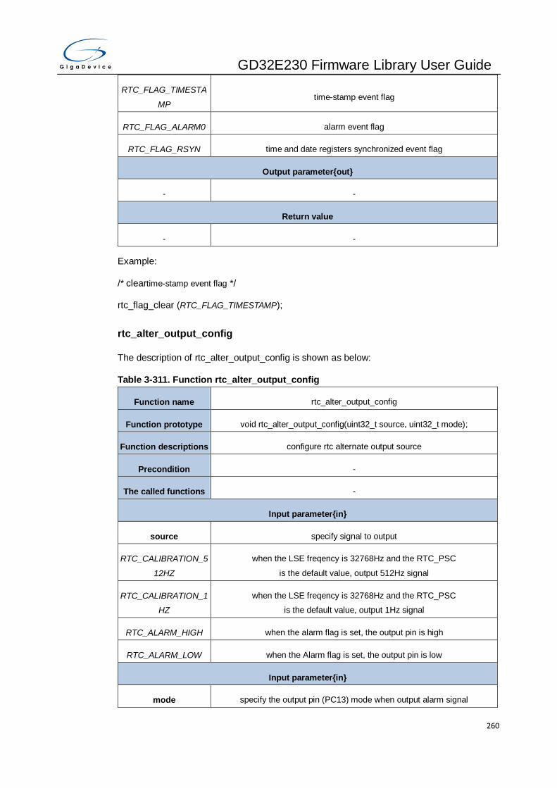
GD32E230 Firmware Library User Guide
260
RTC_FLAG_TIMESTA
MP time-stamp event flag
RTC_FLAG_ALARM0 alarm event flag
RTC_FLAG_RSYN time and date registers synchronized event flag
Output parameter{out}
- -
Return value
- -
Example:
/* cleartime-stamp event flag */
rtc_flag_clear (RTC_FLAG_TIMESTAMP);
rtc_alter_output_config
The description of rtc_alter_output_config is shown as below:
Table 3-311. Function rtc_alter_output_config
Function name rtc_alter_output_config
Function prototype void rtc_alter_output_config(uint32_t source, uint32_t mode);
Function descriptions configure rtc alternate output source
Precondition -
The called functions -
Input parameter{in}
source specify signal to output
RTC_CALIBRATION_5
12HZ
when the LSE freqency is 32768Hz and the RTC_PSC
is the default value, output 512Hz signal
RTC_CALIBRATION_1
HZ
when the LSE freqency is 32768Hz and the RTC_PSC
is the default value, output 1Hz signal
RTC_ALARM_HIGH when the alarm flag is set, the output pin is high
RTC_ALARM_LOW when the Alarm flag is set, the output pin is low
Input parameter{in}
mode specify the output pin (PC13) mode when output alarm signal
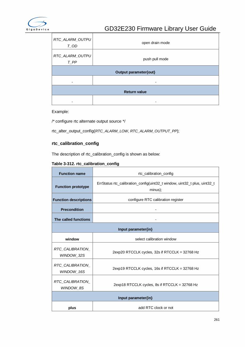
GD32E230 Firmware Library User Guide
261
RTC_ALARM_OUTPU
T_OD open drain mode
RTC_ALARM_OUTPU
T_PP push pull mode
Output parameter{out}
- -
Return value
- -
Example:
/* configure rtc alternate output source */
rtc_alter_output_config(RTC_ALARM_LOW, RTC_ALARM_OUTPUT_PP);
rtc_calibration_config
The description of rtc_calibration_config is shown as below:
Table 3-312. rtc_calibration_config
Function name rtc_calibration_config
Function prototype ErrStatus rtc_calibration_config(uint32_t window, uint32_t plus, uint32_t
minus);
Function descriptions configure RTC calibration register
Precondition -
The called functions -
Input parameter{in}
window select calibration window
RTC_CALIBRATION_
WINDOW_32S 2exp20 RTCCLK cycles, 32s if RTCCLK = 32768 Hz
RTC_CALIBRATION_
WINDOW_16S 2exp19 RTCCLK cycles, 16s if RTCCLK = 32768 Hz
RTC_CALIBRATION_
WINDOW_8S 2exp18 RTCCLK cycles, 8s if RTCCLK = 32768 Hz
Input parameter{in}
plus add RTC clock or not

GD32E230 Firmware Library User Guide
262
RTC_CALIBRATION_P
LUS_SET add one RTC clock every 2048 rtc clock
RTC_CALIBRATION_P
LUS_RESET no effect
Input parameter{in}
minus the RTC clock to minus during the calibration window(0x0 - 0x1FF)
Output parameter{out}
- -
Return value
ErrStatus ERROR or SUCCESS
Example:
/* configure RTC calibration register*/
ErrStatus error_status = rtc_calibration_config(RTC_CALIBRATION_WINDOW_32S,
RTC_CALIBRATION_PLUS_SET, 0x1FF);
rtc_hour_adjust
The description of rtc_hour_adjust is shown as below:
Table 3-313. rtc_hour_adjust
Function name rtc_hour_adjust
Function prototype void rtc_hour_adjust(uint32_t operation);
Function descriptions adjust the daylight saving time by adding or substracting one hour from the
current time
Precondition -
The called functions -
Input parameter{in}
operation hour ajustment operation
RTC_CTL_A1H add one hour
RTC_CTL_S1H substract one hour
Output parameter{out}
- -
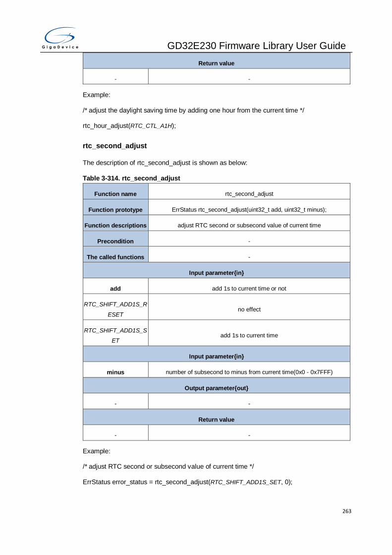
GD32E230 Firmware Library User Guide
263
Return value
- -
Example:
/* adjust the daylight saving time by adding one hour from the current time */
rtc_hour_adjust(RTC_CTL_A1H);
rtc_second_adjust
The description of rtc_second_adjust is shown as below:
Table 3-314. rtc_second_adjust
Function name rtc_second_adjust
Function prototype ErrStatus rtc_second_adjust(uint32_t add, uint32_t minus);
Function descriptions adjust RTC second or subsecond value of current time
Precondition -
The called functions -
Input parameter{in}
add add 1s to current time or not
RTC_SHIFT_ADD1S_R
ESET no effect
RTC_SHIFT_ADD1S_S
ET add 1s to current time
Input parameter{in}
minus number of subsecond to minus from current time(0x0 - 0x7FFF)
Output parameter{out}
- -
Return value
- -
Example:
/* adjust RTC second or subsecond value of current time */
ErrStatus error_status = rtc_second_adjust(RTC_SHIFT_ADD1S_SET, 0);
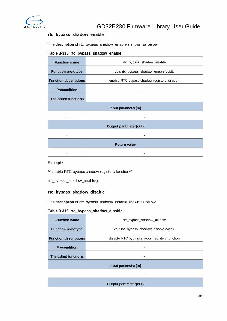
GD32E230 Firmware Library User Guide
264
rtc_bypass_shadow_enable
The description of rtc_bypass_shadow_enableis shown as below:
Table 3-315. rtc_bypass_shadow_enable
Function name rtc_bypass_shadow_enable
Function prototype void rtc_bypass_shadow_enable(void);
Function descriptions enable RTC bypass shadow registers function
Precondition -
The called functions -
Input parameter{in}
- -
Output parameter{out}
- -
Return value
- -
Example:
/* enable RTC bypass shadow registers function*/
rtc_bypass_shadow_enable();
rtc_bypass_shadow_disable
The description of rtc_bypass_shadow_disable shown as below:
Table 3-316. rtc_bypass_shadow_disable
Function name rtc_bypass_shadow_disable
Function prototype void rtc_bypass_shadow_disable (void);
Function descriptions disable RTC bypass shadow registers function
Precondition -
The called functions -
Input parameter{in}
- -
Output parameter{out}
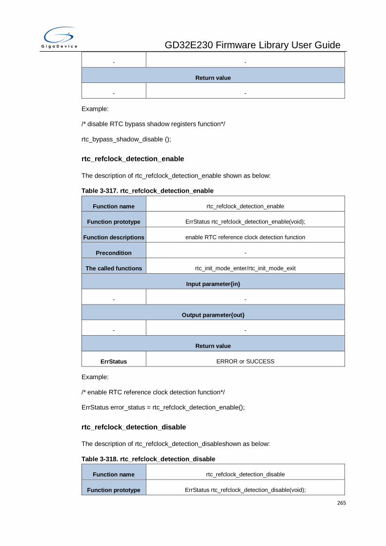
GD32E230 Firmware Library User Guide
265
- -
Return value
- -
Example:
/* disable RTC bypass shadow registers function*/
rtc_bypass_shadow_disable ();
rtc_refclock_detection_enable
The description of rtc_refclock_detection_enable shown as below:
Table 3-317. rtc_refclock_detection_enable
Function name rtc_refclock_detection_enable
Function prototype ErrStatus rtc_refclock_detection_enable(void);
Function descriptions enable RTC reference clock detection function
Precondition -
The called functions rtc_init_mode_enter/rtc_init_mode_exit
Input parameter{in}
- -
Output parameter{out}
- -
Return value
ErrStatus ERROR or SUCCESS
Example:
/* enable RTC reference clock detection function*/
ErrStatus error_status = rtc_refclock_detection_enable();
rtc_refclock_detection_disable
The description of rtc_refclock_detection_disableshown as below:
Table 3-318. rtc_refclock_detection_disable
Function name rtc_refclock_detection_disable
Function prototype ErrStatus rtc_refclock_detection_disable(void);
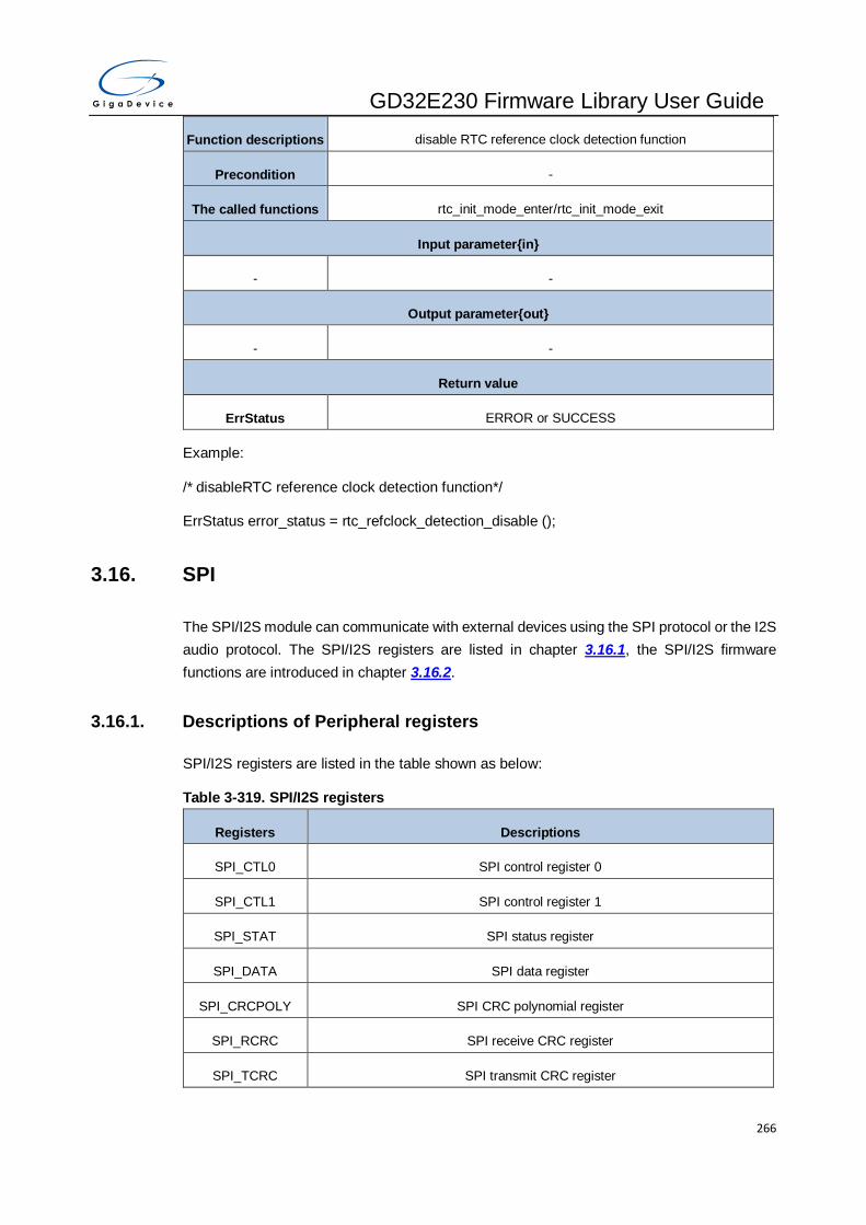
GD32E230 Firmware Library User Guide
266
Function descriptions disable RTC reference clock detection function
Precondition -
The called functions rtc_init_mode_enter/rtc_init_mode_exit
Input parameter{in}
- -
Output parameter{out}
- -
Return value
ErrStatus ERROR or SUCCESS
Example:
/* disableRTC reference clock detection function*/
ErrStatus error_status = rtc_refclock_detection_disable ();
3.16. SPI
The SPI/I2S module can communicate with external devices using the SPI protocol or the I2S
audio protocol. The SPI/I2S registers are listed in chapter 3.16.1, the SPI/I2S firmware
functions are introduced in chapter 3.16.2.
3.16.1. Descriptions of Peripheral registers
SPI/I2S registers are listed in the table shown as below:
Table 3-319. SPI/I2S registers
Registers Descriptions
SPI_CTL0 SPI control register 0
SPI_CTL1 SPI control register 1
SPI_STAT SPI status register
SPI_DATA SPI data register
SPI_CRCPOLY SPI CRC polynomial register
SPI_RCRC SPI receive CRC register
SPI_TCRC SPI transmit CRC register

GD32E230 Firmware Library User Guide
267
Registers Descriptions
SPI_I2SCTL SPI/I2S control register
SPI_I2SPSC SPI/I2S clock prescaler register
SPI_QCTL SPI quad mode control register
3.16.2. Descriptions of Peripheral functions
SPI/I2S firmware functions are listed in the table shown as below:
Table 3-320. SPI/I2S firmware function
Function name Function description
spi_i2s_deinit reset SPI and I2S peripheral
spi_struct_para_init initialize the parameters of SPI struct with the default values
spi_init initialize SPI peripheral parameter
spi_enable enable SPI
spi_disable disable SPI
i2s_init initialize I2S peripheral parameter
i2s_psc_config configure I2S peripheral prescaler
i2s_enable enable I2S
i2s_disable disable I2S
spi_nss_output_enable enable SPI NSS output function
spi_nss_output_disable disable SPI NSS output function
spi_nss_internal_high SPI NSS pin high level in software mode
spi_nss_internal_low SPI NSS pin low level in software mode
spi_dma_enable enable SPI DMA function
spi_dma_disable disable SPI DMA function
spi_i2s_data_frame_format_config configure SPI/I2S data frame format
spi_i2s_data_transmit SPI transmit data
spi_i2s_data_receive SPI receive data
spi_bidirectional_transfer_config configure SPI bidirectional transfer direction
spi_crc_polynomial_set set SPI CRC polynomial

GD32E230 Firmware Library User Guide
268
Function name Function description
spi_crc_polynomial_get get SPI CRC polynomial
spi_crc_on turn on SPI CRC function
spi_crc_off turn off SPI CRC function
spi_crc_next SPI next data is CRC value
spi_crc_get get SPI CRC send value or receive value
spi_ti_mode_enable enable SPI TI mode
spi_ti_mode_disable disable SPI TI mode
spi_nssp_mode_enable enable SPI NSS pulse mode
spi_nssp_mode_disable disable SPI NSS pulse mode
qspi_enable enable quad wire SPI
qspi_disable disable quad wire SPI
qspi_write_enable enable quad wire SPI write
qspi_read_enable enable quad wire SPI read
qspi_io23_output_enable enable quad wire SPI_IO2 and SPI_IO3 pin output
qspi_io23_output_disable disable quad wire SPI_IO2 and SPI_IO3 pin output
spi_i2s_interrupt_enable enable SPI and I2S interrupt
spi_i2s_interrupt_disable disable SPI and I2S interrupt
spi_i2s_interrupt_flag_get get SPI and I2S interrupt status
spi_i2s_flag_get get SPI and I2S flag status
spi_crc_error_clear clear SPI CRC error flag status
spi_fifo_access_size_config configure SPI access size to FIFO(8-bit or 16-bit)
spi_transmit_odd_config configure SPI total number of data transmitting by DMA is odd
or not
spi_receive_odd_config configure SPI total number of data receiving by DMA is odd or
not
spi_crc_length_set set CRC length
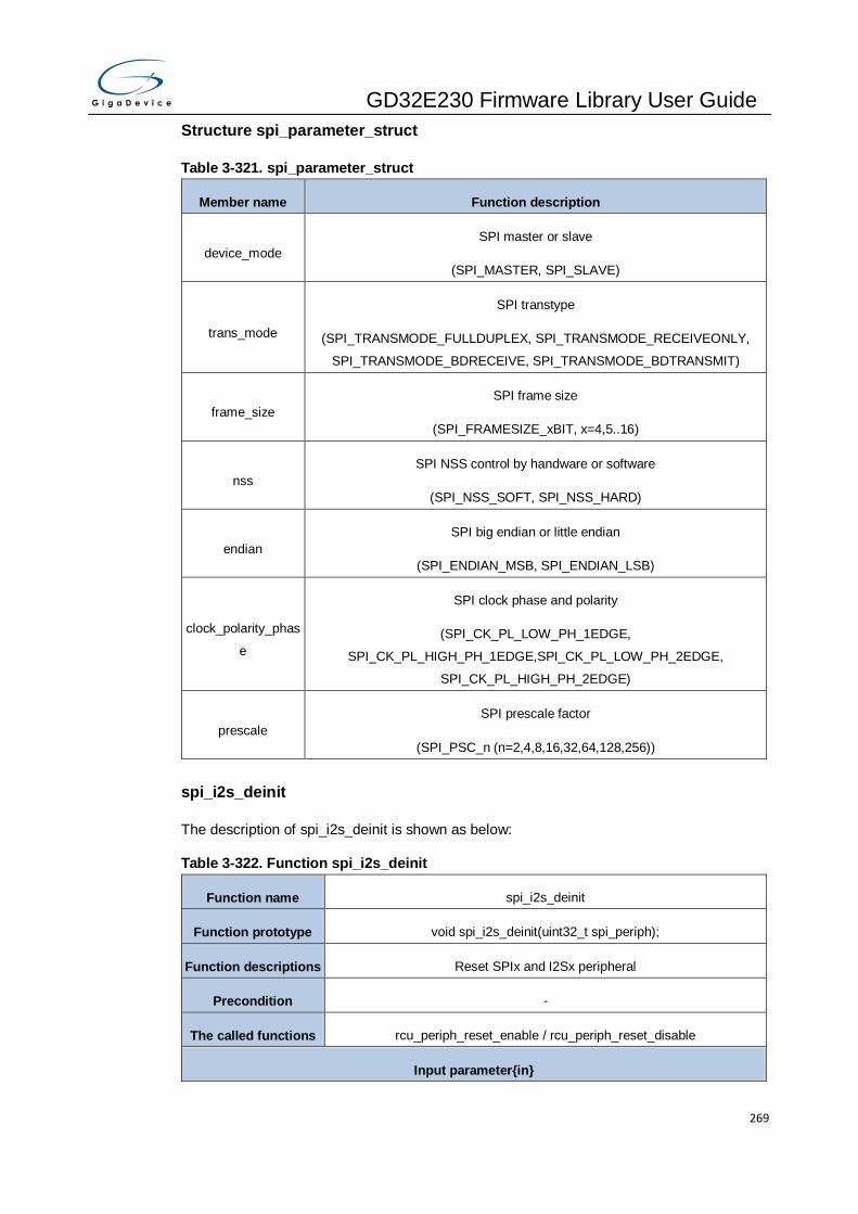
GD32E230 Firmware Library User Guide
269
Structure spi_parameter_struct
Table 3-321. spi_parameter_struct
Member name Function description
device_mode
SPI master or slave
(SPI_MASTER, SPI_SLAVE)
trans_mode
SPI transtype
(SPI_TRANSMODE_FULLDUPLEX, SPI_TRANSMODE_RECEIVEONLY,
SPI_TRANSMODE_BDRECEIVE, SPI_TRANSMODE_BDTRANSMIT)
frame_size
SPI frame size
(SPI_FRAMESIZE_xBIT, x=4,5..16)
nss
SPI NSS control by handware or software
(SPI_NSS_SOFT, SPI_NSS_HARD)
endian
SPI big endian or little endian
(SPI_ENDIAN_MSB, SPI_ENDIAN_LSB)
clock_polarity_phas
e
SPI clock phase and polarity
(SPI_CK_PL_LOW_PH_1EDGE,
SPI_CK_PL_HIGH_PH_1EDGE,SPI_CK_PL_LOW_PH_2EDGE,
SPI_CK_PL_HIGH_PH_2EDGE)
prescale
SPI prescale factor
(SPI_PSC_n (n=2,4,8,16,32,64,128,256))
spi_i2s_deinit
The description of spi_i2s_deinit is shown as below:
Table 3-322. Function spi_i2s_deinit
Function name spi_i2s_deinit
Function prototype void spi_i2s_deinit(uint32_t spi_periph);
Function descriptions Reset SPIx and I2Sx peripheral
Precondition -
The called functions rcu_periph_reset_enable / rcu_periph_reset_disable
Input parameter{in}
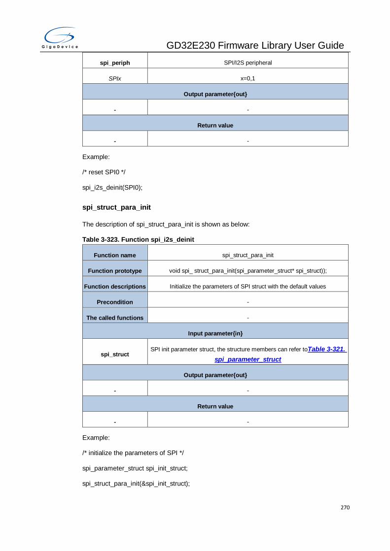
GD32E230 Firmware Library User Guide
270
spi_periph SPI/I2S peripheral
SPIx x=0,1
Output parameter{out}
- -
Return value
- -
Example:
/* reset SPI0 */
spi_i2s_deinit(SPI0);
spi_struct_para_init
The description of spi_struct_para_init is shown as below:
Table 3-323. Function spi_i2s_deinit
Function name spi_struct_para_init
Function prototype void spi_ struct_para_init(spi_parameter_struct* spi_struct));
Function descriptions Initialize the parameters of SPI struct with the default values
Precondition -
The called functions -
Input parameter{in}
spi_struct SPI init parameter struct, the structure members can refer toTable 3-321.
spi_parameter_struct
Output parameter{out}
- -
Return value
- -
Example:
/* initialize the parameters of SPI */
spi_parameter_struct spi_init_struct;
spi_struct_para_init(&spi_init_struct);

GD32E230 Firmware Library User Guide
271
spi_init
The description of spi_init is shown as below:
Table 3-324. Function spi_init
Function name spi_init
Function prototype ErrStatus spi_init(uint32_t spi_periph, spi_parameter_struct* spi_struct);
Function descriptions Initialize SPIx peripheral parameter
Precondition -
The called functions -
Input parameter{in}
spi_periph SPI peripheral
SPIx x=0,1
Input parameter{in}
spi_struct
SPI parameter initialization stuct, the structure members can refer to
members of the structureparameter_struct
Member name Function description
device_mode
SPI master or slave
(SPI_MASTER, SPI_SLAVE)
Output parameter{out}
- -
Return value
ErrStatus ERROR or SUCCESS
Example:
/* initialize SPI0 */
spi_parameter_struct spi_init_struct;
ErrStatus errstatus = ERROR;
spi_init_struct.trans_mode = SPI_TRANSMODE_BDTRANSMIT;
spi_init_struct.device_mode = SPI_MASTER;
spi_init_struct.frame_size = SPI_FRAMESIZE_8BIT;
spi_init_struct.clock_polarity_phase = SPI_CK_PL_HIGH_PH_2EDGE;

GD32E230 Firmware Library User Guide
272
spi_init_struct.nss = SPI_NSS_SOFT;
spi_init_struct.prescale = SPI_PSC_8;
spi_init_struct.endian = SPI_ENDIAN_MSB;
errstatus = spi_init(SPI0, &spi_init_struct);
spi_enable
The description of spi_enable is shown as below:
Table 3-325. Function spi_enable
Function name spi_enable
Function prototype void spi_enable(uint32_t spi_periph);
Function descriptions Enable SPIx
Precondition -
The called functions -
Input parameter{in}
spi_periph SPI peripheral
SPIx x=0,1
Output parameter{out}
- -
Return value
- -
Example:
/* enable SPI0 */
spi_enable(SPI0);
spi_disable
The description of spi_disable is shown as below:
Table 3-326. Function spi_disable
Function name spi_disable
Function prototype void spi_disable(uint32_t spi_periph);
Function descriptions Disable SPIx

GD32E230 Firmware Library User Guide
273
Precondition -
The called functions -
Input parameter{in}
spi_periph SPI peripheral
SPIx x=0,1
Output parameter{out}
- -
Return value
- -
Example:
/* disable SPI0 */
spi_disable(SPI0);
i2s_init
The description of i2s_init is shown as below:
Table 3-327. Function i2s_init
Function name i2s_init
Function prototype void i2s_init(uint32_t spi_periph,uint32_t mode, uint32_t standard, uint32_t
ckpl);
Function descriptions Initialize I2S0 peripheral parameter
Precondition -
The called functions -
Input parameter{in}
spi_periph I2S0 peripheral
SPIx x=0
Input parameter{in}
mode I2S operation mode
I2S_MODE_SLAVETX I2S slave transmit mode
I2S_MODE_SLAVERX I2S slave receive mode
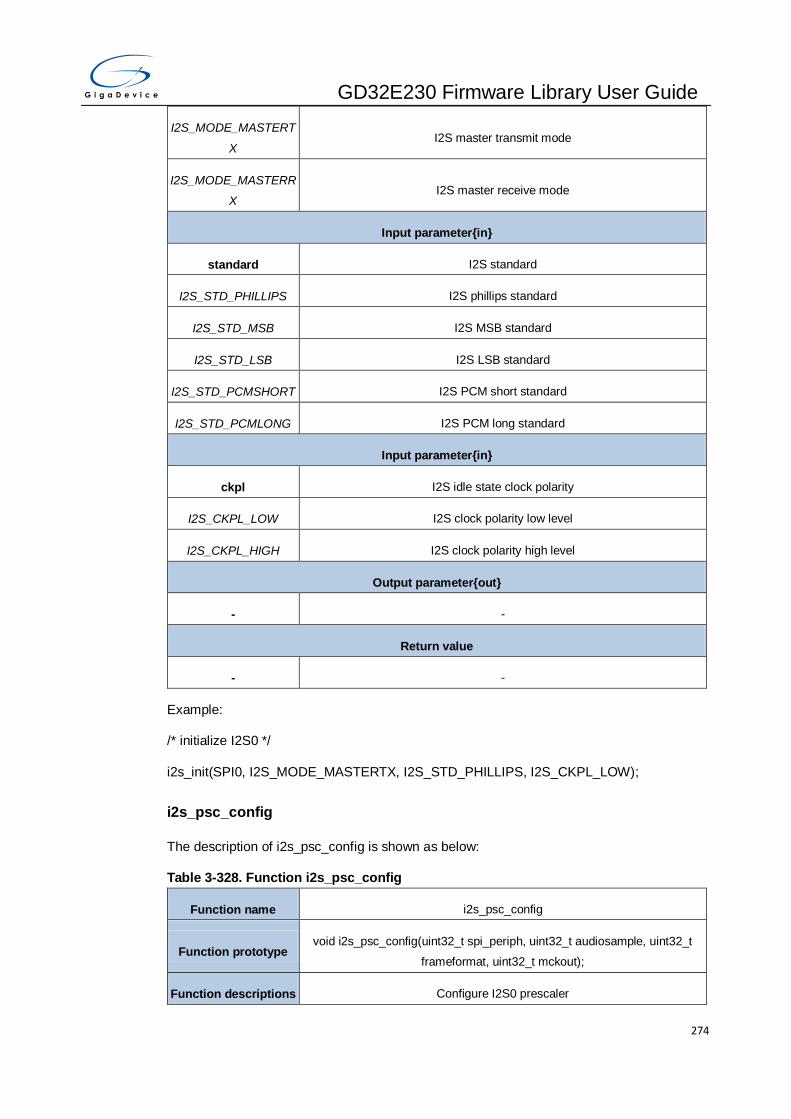
GD32E230 Firmware Library User Guide
274
I2S_MODE_MASTERT
X I2S master transmit mode
I2S_MODE_MASTERR
X I2S master receive mode
Input parameter{in}
standard I2S standard
I2S_STD_PHILLIPS I2S phillips standard
I2S_STD_MSB I2S MSB standard
I2S_STD_LSB I2S LSB standard
I2S_STD_PCMSHORT I2S PCM short standard
I2S_STD_PCMLONG I2S PCM long standard
Input parameter{in}
ckpl I2S idle state clock polarity
I2S_CKPL_LOW I2S clock polarity low level
I2S_CKPL_HIGH I2S clock polarity high level
Output parameter{out}
- -
Return value
- -
Example:
/* initialize I2S0 */
i2s_init(SPI0, I2S_MODE_MASTERTX, I2S_STD_PHILLIPS, I2S_CKPL_LOW);
i2s_psc_config
The description of i2s_psc_config is shown as below:
Table 3-328. Function i2s_psc_config
Function name i2s_psc_config
Function prototype void i2s_psc_config(uint32_t spi_periph, uint32_t audiosample, uint32_t
frameformat, uint32_t mckout);
Function descriptions Configure I2S0 prescaler
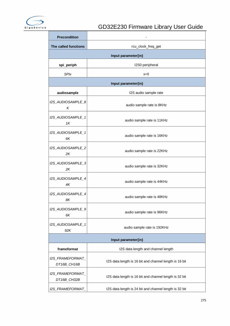
GD32E230 Firmware Library User Guide
275
Precondition -
The called functions rcu_clock_freq_get
Input parameter{in}
spi_periph I2S0 peripheral
SPIx x=0
Input parameter{in}
audiosample I2S audio sample rate
I2S_AUDIOSAMPLE_8
K audio sample rate is 8KHz
I2S_AUDIOSAMPLE_1
1K audio sample rate is 11KHz
I2S_AUDIOSAMPLE_1
6K audio sample rate is 16KHz
I2S_AUDIOSAMPLE_2
2K audio sample rate is 22KHz
I2S_AUDIOSAMPLE_3
2K audio sample rate is 32KHz
I2S_AUDIOSAMPLE_4
4K audio sample rate is 44KHz
I2S_AUDIOSAMPLE_4
8K audio sample rate is 48KHz
I2S_AUDIOSAMPLE_9
6K audio sample rate is 96KHz
I2S_AUDIOSAMPLE_1
92K audio sample rate is 192KHz
Input parameter{in}
frameformat I2S data length and channel length
I2S_FRAMEFORMAT_
DT16B_CH16B I2S data length is 16 bit and channel length is 16 bit
I2S_FRAMEFORMAT_
DT16B_CH32B I2S data length is 16 bit and channel length is 32 bit
I2S_FRAMEFORMAT_ I2S data length is 24 bit and channel length is 32 bit

GD32E230 Firmware Library User Guide
276
DT24B_CH32B
I2S_FRAMEFORMAT_
DT32B_CH32B I2S data length is 32 bit and channel length is 32 bit
Input parameter{in}
mckout I2S master clock output
I2S_MCKOUT_ENABL
E I2S master clock output enable
I2S_MCKOUT_DISABL
E I2S master clock output disable
Output parameter{out}
- -
Return value
- -
Example:
/* configure I2S0 prescaler */
i2s_psc_config(SPI0, I2S_AUDIOSAMPLE_44K, I2S_FRAMEFORMAT_DT16B_CH16B,
I2S_MCKOUT_DISABLE);
i2s_enable
The description of i2s_enable is shown as below:
Table 3-329. Function i2s_enable
Function name i2s_enable
Function prototype void i2s_enable(uint32_t spi_periph);
Function descriptions Enable I2S0
Precondition -
The called functions -
Input parameter{in}
spi_periph I2S0 peripheral
SPIx x=0
Output parameter{out}
- -

GD32E230 Firmware Library User Guide
277
Return value
- -
Example:
/* enable I2S0*/
i2s_enable(SPI0);
i2s_disable
The description of i2s_disable is shown as below:
Table 3-330. Function i2s_disable
Function name i2s_disable
Function prototype void i2s_disable(uint32_t spi_periph);
Function descriptions Disable I2S0
Precondition -
The called functions -
Input parameter{in}
spi_periph I2S0 peripheral
SPIx x=0
Output parameter{out}
- -
Return value
- -
Example:
/* disable I2S0*/
i2s_disable(SPI0);
spi_nss_output_enable
The description of spi_nss_output_enable is shown as below:
Table 3-331. Function spi_nss_output_enable
Function name spi_nss_output_enable
Function prototype void spi_nss_output_enable(uint32_t spi_periph);
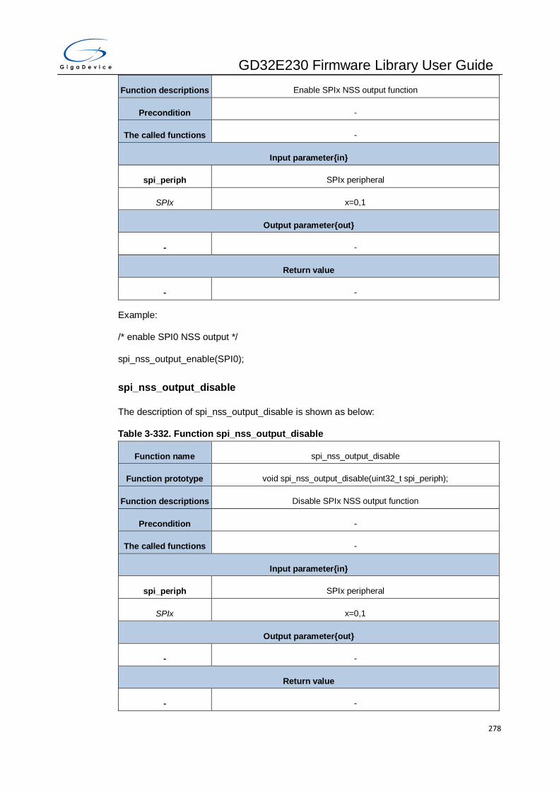
GD32E230 Firmware Library User Guide
278
Function descriptions Enable SPIx NSS output function
Precondition -
The called functions -
Input parameter{in}
spi_periph SPIx peripheral
SPIx x=0,1
Output parameter{out}
- -
Return value
- -
Example:
/* enable SPI0 NSS output */
spi_nss_output_enable(SPI0);
spi_nss_output_disable
The description of spi_nss_output_disable is shown as below:
Table 3-332. Function spi_nss_output_disable
Function name spi_nss_output_disable
Function prototype void spi_nss_output_disable(uint32_t spi_periph);
Function descriptions Disable SPIx NSS output function
Precondition -
The called functions -
Input parameter{in}
spi_periph SPIx peripheral
SPIx x=0,1
Output parameter{out}
- -
Return value
- -

GD32E230 Firmware Library User Guide
279
Example:
/* disable SPI0 NSS output */
spi_nss_output_disable(SPI0);
spi_nss_internal_high
The description of spi_nss_internal_high is shown as below:
Table 3-333. Function spi_nss_internal_high
Function name spi_nss_internal_high
Function prototype void spi_nss_internal_high(uint32_t spi_periph);
Function descriptions SPI NSS pin high level in software mode
Precondition -
The called functions -
Input parameter{in}
spi_periph SPI peripheral
SPIx x=0,1
Output parameter{out}
- -
Return value
- -
Example:
/* SPI0 NSS pin is pulled high level in software mode */
spi_nss_internal_high(SPI0);
spi_nss_internal_low
The description of spi_nss_internal_low is shown as below:
Table 3-334. Function spi_nss_internal_low
Function name spi_nss_internal_low
Function prototype void spi_nss_internal_low(uint32_t spi_periph);
Function descriptions SPI NSS pin low level in software mode
Precondition -

GD32E230 Firmware Library User Guide
280
The called functions -
Input parameter{in}
spi_periph SPI peripheral
SPIx x=0,1
Output parameter{out}
- -
Return value
- -
Example:
/* SPI0 NSS pin is pulled low level in software mode */
spi_nss_internal_low(SPI0);
spi_dma_enable
The description of spi_dma_enable is shown as below:
Table 3-335. Function spi_dma_enable
Function name spi_dma_enable
Function prototype void spi_dma_enable(uint32_t spi_periph, uint8_t dma);
Function descriptions Enable SPIx DMA function
Precondition -
The called functions -
Input parameter{in}
spi_periph SPI peripheral
SPIx x=0,1
Input parameter{in}
dma SPI DMA mode
SPI_DMA_TRANSMIT SPI transmit data use DMA
SPI_DMA_RECEIVE SPI receive data use DMA
Output parameter{out}
- -

GD32E230 Firmware Library User Guide
281
Return value
- -
Example:
/* enable SPI0 transmit data DMA function */
spi_dma_enable(SPI0, SPI_DMA_TRANSMIT);
spi_dma_disable
The description of spi_dma_disable is shown as below:
Table 3-336. Function spi_dma_disable
Function name spi_dma_disable
Function prototype void spi_dma_disable(uint32_t spi_periph, uint8_t dma);
Function descriptions Disable SPIx DMA function
Precondition -
The called functions -
Input parameter{in}
spi_periph SPI peripheral
SPIx x=0,1
Input parameter{in}
dma SPI DMA mode
SPI_DMA_TRANSMIT SPI transmit data use DMA
SPI_DMA_RECEIVE SPI receive data use DMA
Output parameter{out}
- -
Return value
- -
Example:
/* disable SPI0 transmit data DMA function */
spi_dma_disable(SPI0, SPI_DMA_TRANSMIT);

GD32E230 Firmware Library User Guide
282
spi_i2s_data_frame_format_config
The description of spi_i2s_data_frame_format_config is shown as below:
Table 3-337. Function spi_i2s_data_frame_format_config
Function name spi_i2s_data_frame_format_config
Function prototype ErrStatus spi_i2s_data_frame_format_config(uint32_t spi_periph, uint16_t
frame_format);
Function descriptions Configure SPIx/I2S0 data frame format
Precondition -
The called functions -
Input parameter{in}
spi_periph SPI peripheral
SPIx x=0,1
Input parameter{in}
frame_format SPI frame size
SPI_FRAMESIZE_xBIT SPI frame size is x bits,x=4,5,6,…,15,16
Output parameter{out}
- -
Return value
ErrStatus ERROR or SUCCESS
Example:
/* configure SPI0/I2S0 data frame format size is 16 bits */
spi_i2s_data_frame_format_config(SPI0, SPI_FRAMESIZE_16BIT);
spi_i2s_data_transmit
The description of spi_i2s_data_transmit is shown as below:
Table 3-338. Function spi_i2s_data_transmit
Function name spi_i2s_data_transmit
Function prototype void spi_i2s_data_transmit(uint32_t spi_periph, uint16_t data);
Function descriptions SPI transmit data
Precondition -

GD32E230 Firmware Library User Guide
283
The called functions -
Input parameter{in}
spi_periph SPI peripheral
SPIx x=0,1
Input parameter{in}
data 16-bit data
Output parameter{out}
- -
Return value
- -
Example:
/* SPI0 transmit data */
spi_i2s_data_transmit(SPI0, spi0_send_array[send_n]);
spi_i2s_data_receive
The description of spi_i2s_data_receive is shown as below:
Table 3-339. Function spi_i2s_data_receive
Function name spi_i2s_data_receive
Function prototype uint16_t spi_i2s_data_receive(uint32_t spi_periph);
Function descriptions SPI receive data
Precondition -
The called functions -
Input parameter{in}
spi_periph SPI peripheral
SPIx x=0,1
Output parameter{out}
- -
Return value
uint16_t 16-bit data
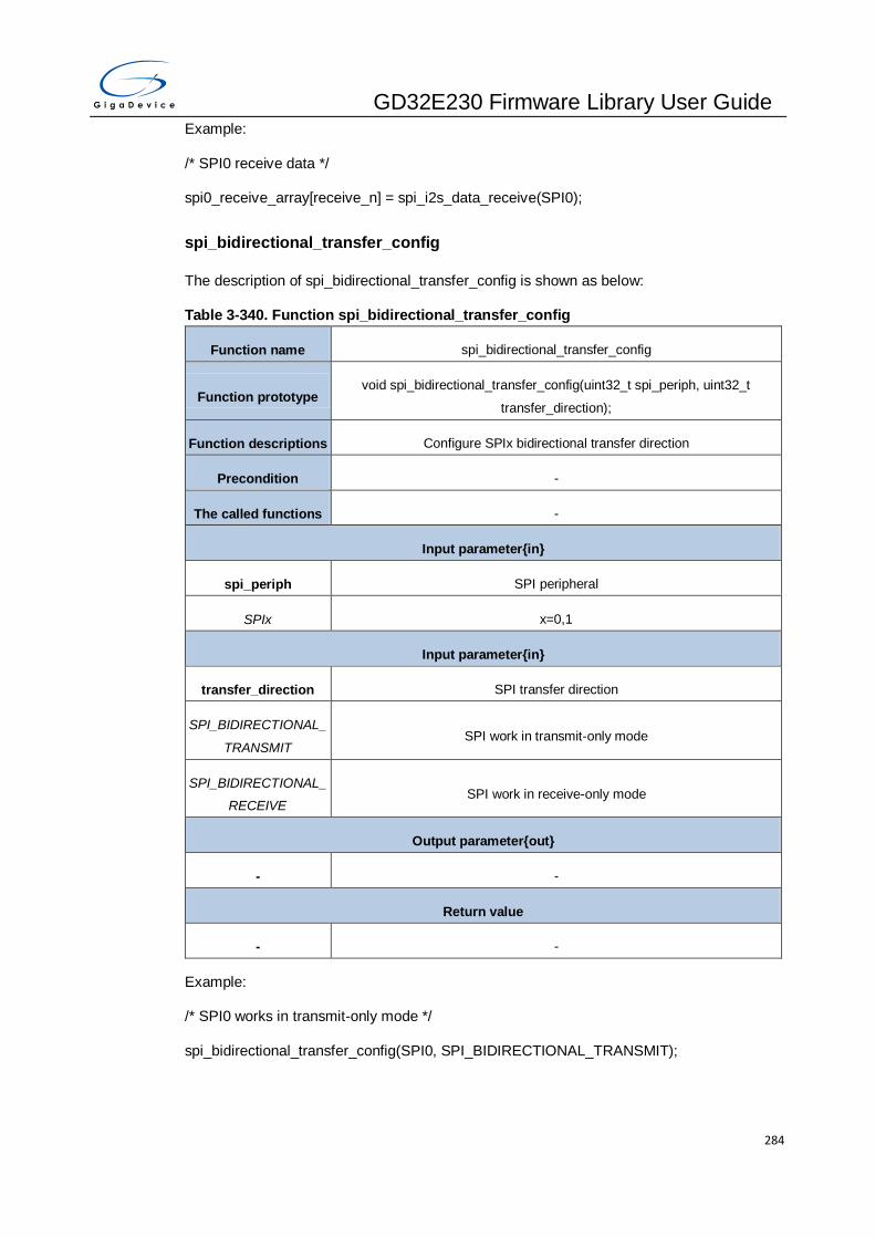
GD32E230 Firmware Library User Guide
284
Example:
/* SPI0 receive data */
spi0_receive_array[receive_n] = spi_i2s_data_receive(SPI0);
spi_bidirectional_transfer_config
The description of spi_bidirectional_transfer_config is shown as below:
Table 3-340. Function spi_bidirectional_transfer_config
Function name spi_bidirectional_transfer_config
Function prototype void spi_bidirectional_transfer_config(uint32_t spi_periph, uint32_t
transfer_direction);
Function descriptions Configure SPIx bidirectional transfer direction
Precondition -
The called functions -
Input parameter{in}
spi_periph SPI peripheral
SPIx x=0,1
Input parameter{in}
transfer_direction SPI transfer direction
SPI_BIDIRECTIONAL_
TRANSMIT SPI work in transmit-only mode
SPI_BIDIRECTIONAL_
RECEIVE SPI work in receive-only mode
Output parameter{out}
- -
Return value
- -
Example:
/* SPI0 works in transmit-only mode */
spi_bidirectional_transfer_config(SPI0, SPI_BIDIRECTIONAL_TRANSMIT);
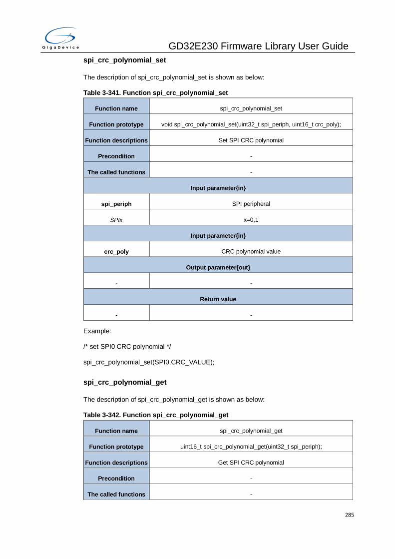
GD32E230 Firmware Library User Guide
285
spi_crc_polynomial_set
The description of spi_crc_polynomial_set is shown as below:
Table 3-341. Function spi_crc_polynomial_set
Function name spi_crc_polynomial_set
Function prototype void spi_crc_polynomial_set(uint32_t spi_periph, uint16_t crc_poly);
Function descriptions Set SPI CRC polynomial
Precondition -
The called functions -
Input parameter{in}
spi_periph SPI peripheral
SPIx x=0,1
Input parameter{in}
crc_poly CRC polynomial value
Output parameter{out}
- -
Return value
- -
Example:
/* set SPI0 CRC polynomial */
spi_crc_polynomial_set(SPI0,CRC_VALUE);
spi_crc_polynomial_get
The description of spi_crc_polynomial_get is shown as below:
Table 3-342. Function spi_crc_polynomial_get
Function name spi_crc_polynomial_get
Function prototype uint16_t spi_crc_polynomial_get(uint32_t spi_periph);
Function descriptions Get SPI CRC polynomial
Precondition -
The called functions -

GD32E230 Firmware Library User Guide
286
Input parameter{in}
spi_periph SPI peripheral
SPIx x=0,1
Output parameter{out}
- -
Return value
uint16_t 16 bit CRC polynomial value
Example:
/* get SPI0 CRC polynomial */
uint16_t crc_val;
crc_val = spi_crc_polynomial_get(SPI0);
spi_crc_on
The description of spi_crc_on is shown as below:
Table 3-343. Function spi_crc_on
Function name spi_crc_on
Function prototype void spi_crc_on(uint32_t spi_periph);
Function descriptions Turn on CRC function
Precondition -
The called functions -
Input parameter{in}
spi_periph SPI peripheral
SPIx x=0,1
Output parameter{out}
- -
Return value
- -
Example:
/* turn on SPI0 CRC function */
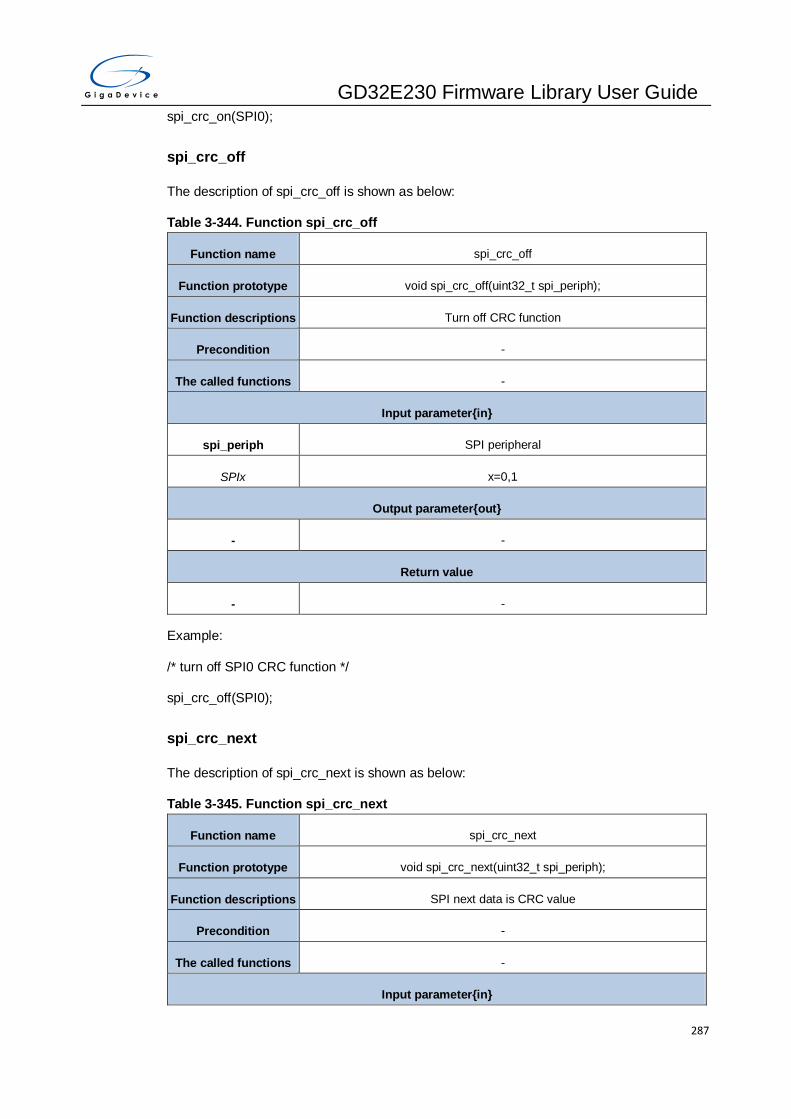
GD32E230 Firmware Library User Guide
287
spi_crc_on(SPI0);
spi_crc_off
The description of spi_crc_off is shown as below:
Table 3-344. Function spi_crc_off
Function name spi_crc_off
Function prototype void spi_crc_off(uint32_t spi_periph);
Function descriptions Turn off CRC function
Precondition -
The called functions -
Input parameter{in}
spi_periph SPI peripheral
SPIx x=0,1
Output parameter{out}
- -
Return value
- -
Example:
/* turn off SPI0 CRC function */
spi_crc_off(SPI0);
spi_crc_next
The description of spi_crc_next is shown as below:
Table 3-345. Function spi_crc_next
Function name spi_crc_next
Function prototype void spi_crc_next(uint32_t spi_periph);
Function descriptions SPI next data is CRC value
Precondition -
The called functions -
Input parameter{in}

GD32E230 Firmware Library User Guide
288
spi_periph SPI peripheral
SPIx x=0,1
Output parameter{out}
- -
Return value
- -
Example:
/* SPI0 next data is CRC value */
spi_crc_next(SPI0);
spi_crc_get
The description of spi_crc_get is shown as below:
Table 3-346. Function spi_crc_get
Function name spi_crc_get
Function prototype uint16_t spi_crc_get(uint32_t spi_periph,uint8_t crc);
Function descriptions Get SPI CRC send value or receive value
Precondition -
The called functions -
Input parameter{in}
spi_periph SPI peripheral
SPIx x=0,1
Input parameter{in}
crc SPI crc value
SPI_CRC_TX get transmit crc value
SPI_CRC_RX get receive crc value
Output parameter{out}
- -
Return value
uint16_t 16-bit CRC value
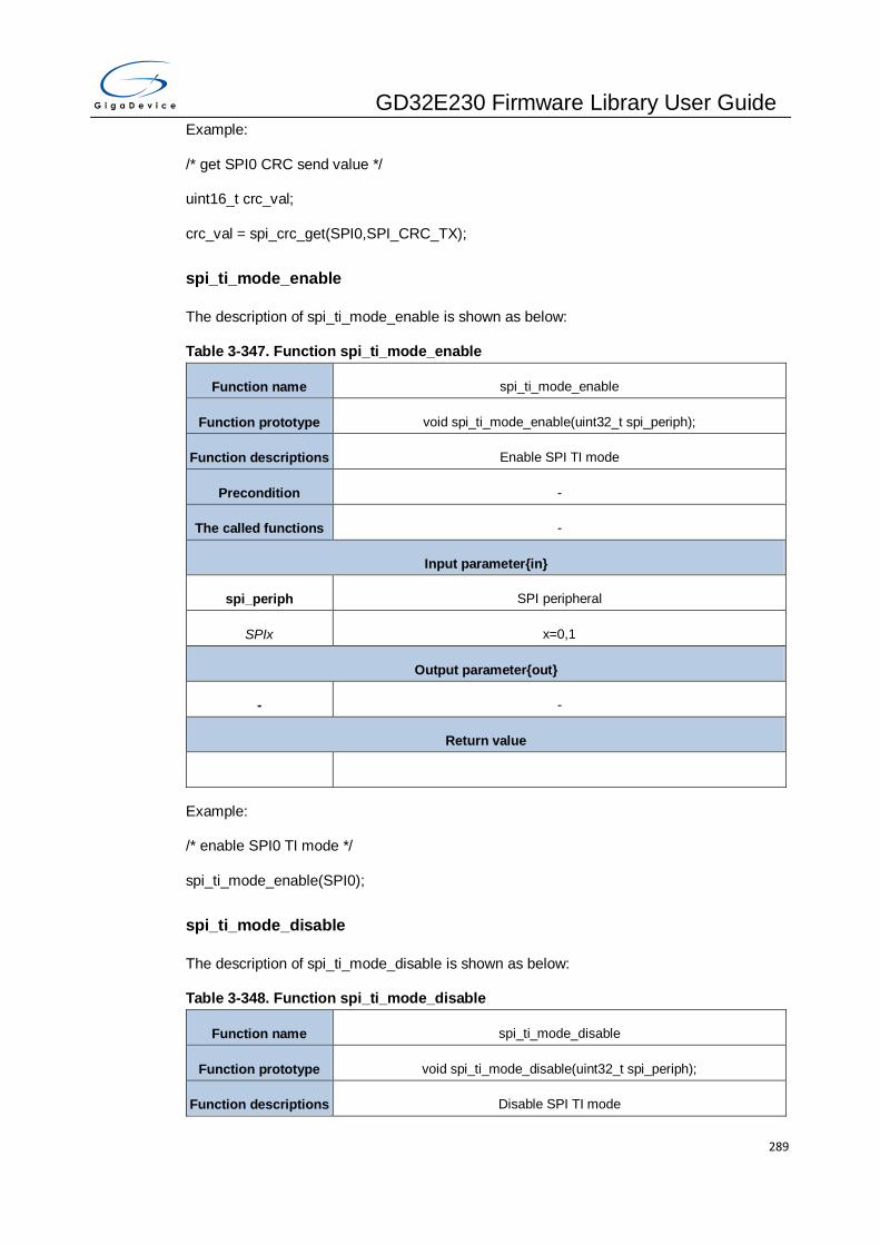
GD32E230 Firmware Library User Guide
289
Example:
/* get SPI0 CRC send value */
uint16_t crc_val;
crc_val = spi_crc_get(SPI0,SPI_CRC_TX);
spi_ti_mode_enable
The description of spi_ti_mode_enable is shown as below:
Table 3-347. Function spi_ti_mode_enable
Function name spi_ti_mode_enable
Function prototype void spi_ti_mode_enable(uint32_t spi_periph);
Function descriptions Enable SPI TI mode
Precondition -
The called functions -
Input parameter{in}
spi_periph SPI peripheral
SPIx x=0,1
Output parameter{out}
- -
Return value
Example:
/* enable SPI0 TI mode */
spi_ti_mode_enable(SPI0);
spi_ti_mode_disable
The description of spi_ti_mode_disable is shown as below:
Table 3-348. Function spi_ti_mode_disable
Function name spi_ti_mode_disable
Function prototype void spi_ti_mode_disable(uint32_t spi_periph);
Function descriptions Disable SPI TI mode

GD32E230 Firmware Library User Guide
290
Precondition -
The called functions -
Input parameter{in}
spi_periph SPI peripheral
SPIx x=0,1
Output parameter{out}
- -
Return value
Example:
/* disable SPI0 TI mode */
spi_ti_mode_disable(SPI0);
spi_nssp_mode_enable
The description of spi_nssp_mode_enable is shown as below:
Table 3-349. Function spi_nssp_mode_enable
Function name spi_ti_mode_enable
Function prototype void spi_ti_mode_enable(uint32_t spi_periph);
Function descriptions Enable SPI NSS pulse mode
Precondition -
The called functions -
Input parameter{in}
spi_periph SPI peripheral
SPIx x=0,1
Output parameter{out}
- -
Return value
Example:
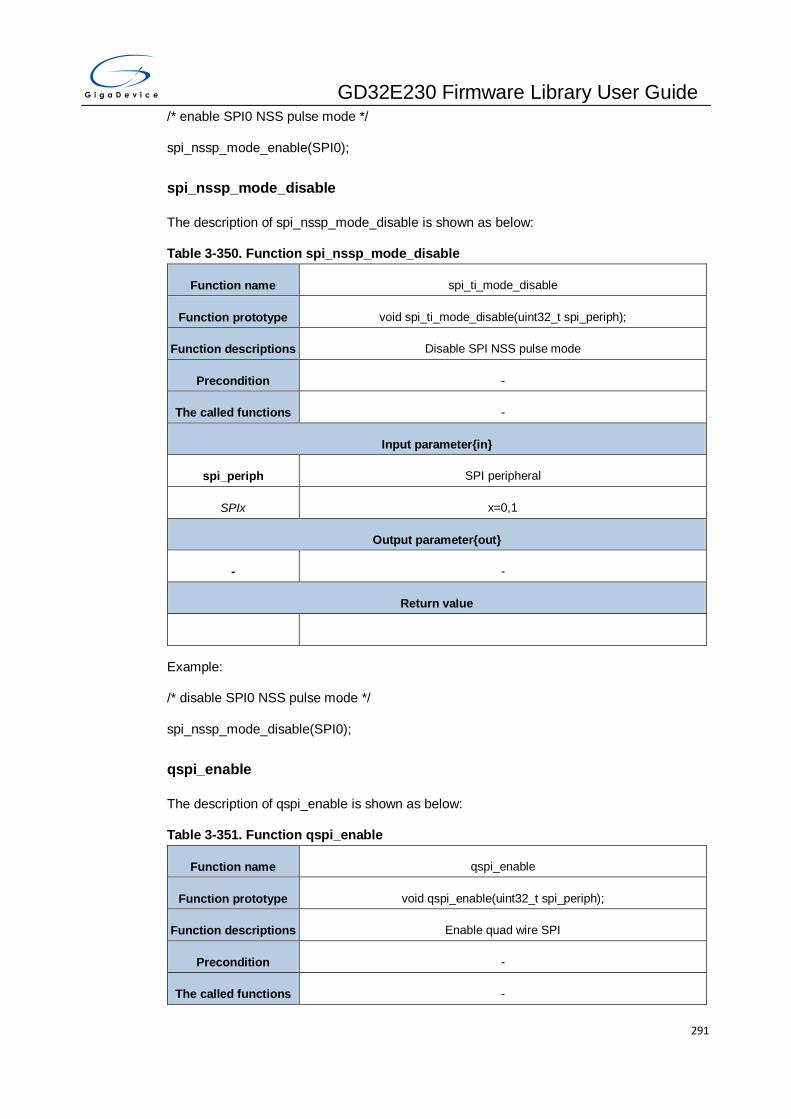
GD32E230 Firmware Library User Guide
291
/* enable SPI0 NSS pulse mode */
spi_nssp_mode_enable(SPI0);
spi_nssp_mode_disable
The description of spi_nssp_mode_disable is shown as below:
Table 3-350. Function spi_nssp_mode_disable
Function name spi_ti_mode_disable
Function prototype void spi_ti_mode_disable(uint32_t spi_periph);
Function descriptions Disable SPI NSS pulse mode
Precondition -
The called functions -
Input parameter{in}
spi_periph SPI peripheral
SPIx x=0,1
Output parameter{out}
- -
Return value
Example:
/* disable SPI0 NSS pulse mode */
spi_nssp_mode_disable(SPI0);
qspi_enable
The description of qspi_enable is shown as below:
Table 3-351. Function qspi_enable
Function name qspi_enable
Function prototype void qspi_enable(uint32_t spi_periph);
Function descriptions Enable quad wire SPI
Precondition -
The called functions -

GD32E230 Firmware Library User Guide
292
Input parameter{in}
spi_periph SPI peripheral
SPIx x=1
Output parameter{out}
- -
Return value
Example:
/* enable SPI1 quad wire mode */
qspi_enable(SPI1);
qspi_disable
The description of qspi_disable is shown as below:
Table 3-352. Function qspi_disable
Function name qspi_disable
Function prototype void qspi_disable(uint32_t spi_periph);
Function descriptions Disable quad wire SPI
Precondition -
The called functions -
Input parameter{in}
spi_periph SPI peripheral
SPIx x=1
Output parameter{out}
- -
Return value
Example:
/* disable SPI1 quad wire mode */
qspi_disable(SPI1);

GD32E230 Firmware Library User Guide
293
qspi_write_enable
The description of qspi_write_enable is shown as below:
Table 3-353. Function qspi_write_enable
Function name qspi_write_enable
Function prototype void qspi_write_enable(uint32_t spi_periph);
Function descriptions Enable quad wire SPI write
Precondition -
The called functions -
Input parameter{in}
spi_periph SPI peripheral
SPIx x=1
Output parameter{out}
- -
Return value
Example:
/* enable SPI1 quad wire write */
qspi_write_enable(SPI1);
qspi_read_enable
The description of qspi_read_enable is shown as below:
Table 3-354. Function qspi_read_enable
Function name qspi_read_enable
Function prototype void qspi_read_enable(uint32_t spi_periph);
Function descriptions Enable quad wire SPI read
Precondition -
The called functions -
Input parameter{in}
spi_periph SPI peripheral

GD32E230 Firmware Library User Guide
294
SPIx x=1
Output parameter{out}
- -
Return value
Example:
/* enable SPI1 quad wire read */
qspi_read_enable(SPI1);
qspi_io23_output_enable
The description of qspi_io23_output_enable is shown as below:
Table 3-355. Function qspi_io23_output_enable
Function name qspi_io23_output_enable
Function prototype void qspi_io23_output_enable(uint32_t spi_periph);
Function descriptions Enable SPI_IO2 and SPI_IO3 pin output
Precondition -
The called functions -
Input parameter{in}
spi_periph SPI peripheral
SPIx x=1
Output parameter{out}
- -
Return value
Example:
/* enable SPI1 SPI_IO2 and SPI_IO3 pin output */
qspi_io23_output_enable(SPI1);
qspi_io23_output_disable
The description of qspi_io23_output_disable is shown as below:

GD32E230 Firmware Library User Guide
295
Table 3-356. Function qspi_io23_output_disable
Function name qspi_io23_output_disable
Function prototype void qspi_io23_output_disable(uint32_t spi_periph);
Function descriptions Disable SPI_IO2 and SPI_IO3 pin output
Precondition -
The called functions -
Input parameter{in}
spi_periph SPI peripheral
SPIx x=1
Output parameter{out}
- -
Return value
Example:
/* disable SPI1 SPI_IO2 and SPI_IO3 pin output */
qspi_io23_output_disable(SPI1);
spi_i2s_interrupt_enable
The description of spi_i2s_interrupt_enable is shown as below:
Table 3-357. Function spi_i2s_interrupt_enable
Function name spi_i2s_interrupt_ enable
Function prototype void spi_i2s_interrupt_enable(uint32_t spi_periph, uint8_t interrupt);
Function descriptions Enable SPIx and I2S0 interrupt
Precondition -
The called functions -
Input parameter{in}
spi_periph SPI peripheral
SPIx x=0,1
Input parameter{in}

GD32E230 Firmware Library User Guide
296
interrupt SPI/I2S interrupt
SPI_I2SINT_TBE transmit buffer empty interrupt
SPI_I2S_INT_RBNE receive buffer not empty interrupt
SPI_I2S_INT_ERR CRC error,configuration error,reception overrun error, transmission
underrun error and format error interrupt
Output parameter{out}
- -
Return value
Example:
/* enable SPI0 transmit buffer empty interrupt */
spi_i2s_interrupt_enable(SPI0,SPI_I2S_INT_TBE);
spi_i2s_interrupt_disable
The description of spi_i2s_interrupt_disable is shown as below:
Table 3-358. Function spi_i2s_interrupt_disable
Function name spi_i2s_interrupt_ disable
Function prototype void spi_i2s_interrupt_disable(uint32_t spi_periph, uint8_t interrupt);
Function descriptions Disable SPIx and I2S0 interrupt
Precondition -
The called functions -
Input parameter{in}
spi_periph SPI peripheral
SPIx x=0,1
Input parameter{in}
interrupt SPI/I2S interrupt
SPI_I2SINT_TBE transmit buffer empty interrupt
SPI_I2S_INT_RBNE receive buffer not empty interrupt
SPI_I2S_INT_ERR CRC error,configuration error,reception overrun error, transmission
underrun error and format error interrupt
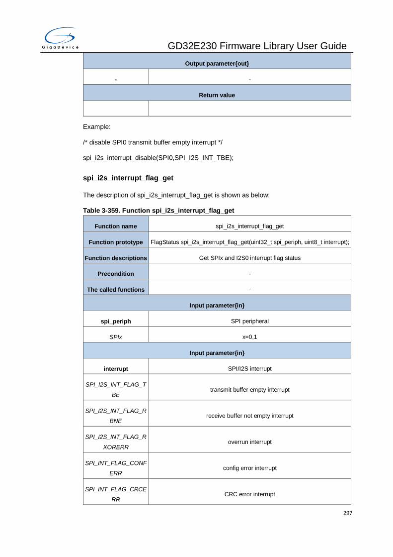
GD32E230 Firmware Library User Guide
297
Output parameter{out}
- -
Return value
Example:
/* disable SPI0 transmit buffer empty interrupt */
spi_i2s_interrupt_disable(SPI0,SPI_I2S_INT_TBE);
spi_i2s_interrupt_flag_get
The description of spi_i2s_interrupt_flag_get is shown as below:
Table 3-359. Function spi_i2s_interrupt_flag_get
Function name spi_i2s_interrupt_flag_get
Function prototype FlagStatus spi_i2s_interrupt_flag_get(uint32_t spi_periph, uint8_t interrupt);
Function descriptions Get SPIx and I2S0 interrupt flag status
Precondition -
The called functions -
Input parameter{in}
spi_periph SPI peripheral
SPIx x=0,1
Input parameter{in}
interrupt SPI/I2S interrupt
SPI_I2S_INT_FLAG_T
BE transmit buffer empty interrupt
SPI_I2S_INT_FLAG_R
BNE receive buffer not empty interrupt
SPI_I2S_INT_FLAG_R
XORERR overrun interrupt
SPI_INT_FLAG_CONF
ERR config error interrupt
SPI_INT_FLAG_CRCE
RR CRC error interrupt

GD32E230 Firmware Library User Guide
298
I2S_INT_FLAG_TXUR
ERR underrun error interrupt
SPI_I2S_INT_FLAG_F
ERR format error interrupt
Output parameter{out}
- -
Return value
FlagStatus SET or RESET
Example:
/* get SPI0 transmit buffer empty interrupt status */
If(RESET != spi_i2s_interrupt_flag_get(SPI0.SPI_I2S_INT_FLAG_TBE)){
while(RESET == spi_i2s_flag_get(SPI0,SPI_FLAG_TBE));
spi_i2s_data_transmit(SPI0,spi0_send_array[send_n++]);
}
spi_i2s_flag_get
The description of spi_i2s_flag_get is shown as below:
Table 3-360. Function spi_i2s_flag_get
Function name spi_i2s_flag_get
Function prototype FlagStatus spi_i2s_flag_get(uint32_t spi_periph, uint8_t interrupt);
Function descriptions Get SPIx and I2S0 flag status
Precondition -
The called functions -
Input parameter{in}
spi_periph SPI peripheral
SPIx x=0,1
Input parameter{in}
flag SPI/I2S flag status
SPI _FLAG_TBE transmit buffer empty flag
SPI _FLAG_RBNE receive buffer not empty flag

GD32E230 Firmware Library User Guide
299
SPI_FLAG_TRANS transmit on-going flag
SPI_FLAG_RXORERR receive overrun error flag
SPI_FLAG_CONFERR mode config error flag
SPI_FLAG_CRCERR CRC error flag
SPI_FLAG_FERR format error interrupt flag
I2S_FLAG_TBE transmit buffer empty flag
I2S_FLAG_RBNE receive buffer not empty flag
I2S_FLAG_TRANS transmit on-going flag
I2S_FLAG_RXORERR overrun error flag
I2S_FLAG_TXURERR underrun error flag
I2S_FLAG_CH channel side flag
Only for SPI1
SPI_TXLVL_EMPTY SPI TXFIFO is empty
SPI_TXLVL_QUARTER
_FULL SPI TXFIFO is a quarter of full
SPI_TXLVL_HAlF_FUL
L SPI TXFIFO is a half of full
SPI_TXLVL_FULL SPI TXFIFO is full
SPI_RXLVL_EMPTY SPI RXFIFO is empty
SPI_RXLVL_QUARTE
R_FULL SPI RXFIFO is a quarter of full
SPI_RXLVL_HAlF_FUL
L SPI RXFIFO is a half of full
SPI_RXLVL_FULL SPI RXFIFO is full
Output parameter{out}
- -
Return value
FlagStatus SET or RESET
Example:
/* get SPI0 transmit buffer empty flag status */

GD32E230 Firmware Library User Guide
300
while(RESET == spi_i2s_flag_get(SPI0,SPI_FLAG_TBE));
spi_i2s_data_transmit(SPI0,spi0_send_array[send_n++]);
spi_crc_error_clear
The description of spi_crc_error_clear is shown as below:
Table 3-361. Function spi_crc_error_clear
Function name spi_crc_error_clear
Function prototype void spi_crc_error_clear(uint32_t spi_periph);
Function descriptions Clear SPI CRC error flag status
Precondition -
The called functions -
Input parameter{in}
spi_periph SPI peripheral
SPIx x=0,1
Output parameter{out}
- -
Return value
Example:
/* clear SPI0CRC error flag status */
spi_crc_error_clear(SPI0);
spi_fifo_access_size_config
The description of spi_fifo_access_size_config is shown as below:
Table 3-362. Function spi_fifo_access_size_config
Function name spi_fifo_access_size_config
Function prototype void spi_fifo_access_size_config(uint32_t spi_periph, uint16_t
fifo_access_size);
Function descriptions Configure SPI1 access size to FIFO(8bit or 16bit)
Precondition -
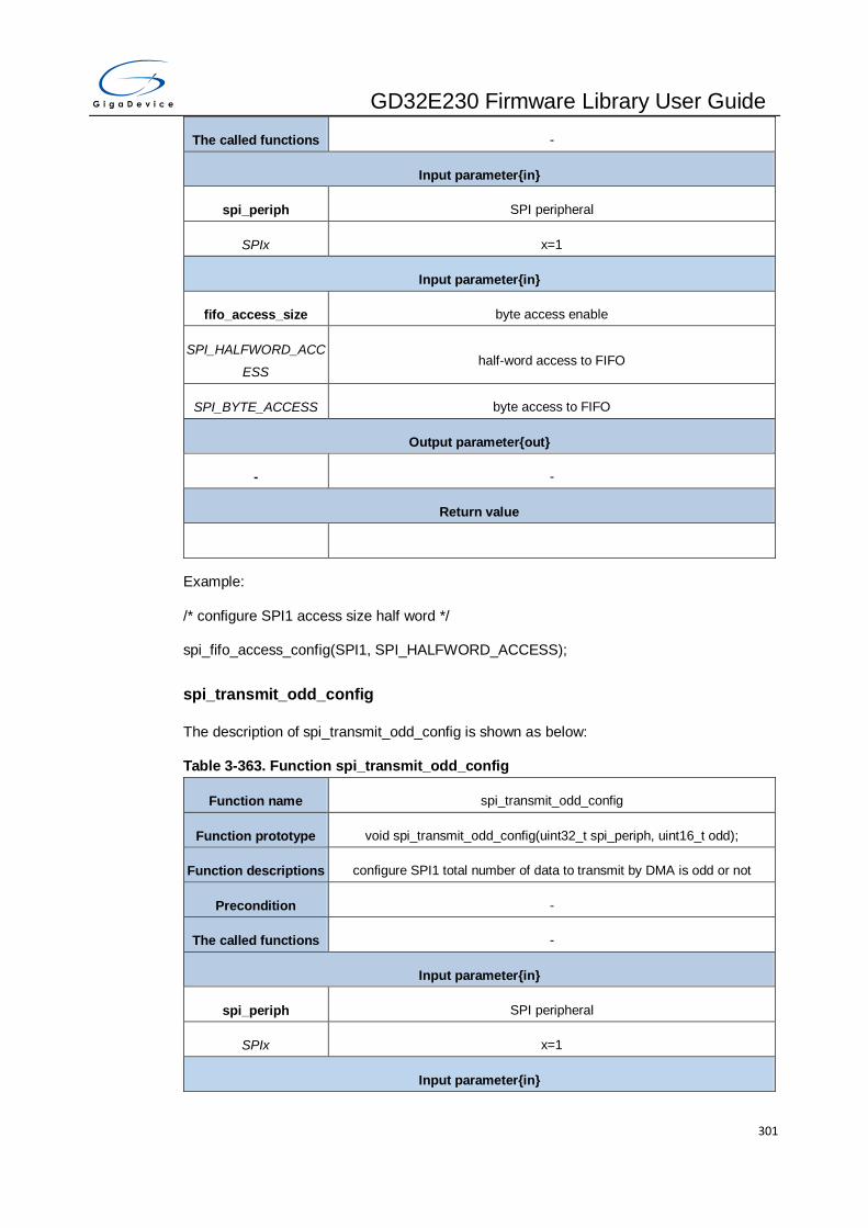
GD32E230 Firmware Library User Guide
301
The called functions -
Input parameter{in}
spi_periph SPI peripheral
SPIx x=1
Input parameter{in}
fifo_access_size byte access enable
SPI_HALFWORD_ACC
ESS half-word access to FIFO
SPI_BYTE_ACCESS byte access to FIFO
Output parameter{out}
- -
Return value
Example:
/* configure SPI1 access size half word */
spi_fifo_access_config(SPI1, SPI_HALFWORD_ACCESS);
spi_transmit_odd_config
The description of spi_transmit_odd_config is shown as below:
Table 3-363. Function spi_transmit_odd_config
Function name spi_transmit_odd_config
Function prototype void spi_transmit_odd_config(uint32_t spi_periph, uint16_t odd);
Function descriptions configure SPI1 total number of data to transmit by DMA is odd or not
Precondition -
The called functions -
Input parameter{in}
spi_periph SPI peripheral
SPIx x=1
Input parameter{in}

GD32E230 Firmware Library User Guide
302
odd odd bytes in TX DMA channel
SPI_TXDMA_EVEN number of byte in TX DMA channel is even
SPI_TXDMA_ODD number of byte in TX DMA channel is odd
Output parameter{out}
- -
Return value
Example:
/* configure SPI1 total number of data to transmit by DMA is odd */
spi_transmit_odd_config(SPI1, SPI_TXDMA_ODD);
spi_receive_odd_config
The description of spi_receive_odd_config is shown as below:
Table 3-364. Function spi_receive_odd_config
Function name spi_receive_odd_config
Function prototype void spi_receive_odd_config(uint32_t spi_periph, uint16_t odd);
Function descriptions configure SPI1 total number of data to receive by DMA is odd or not
Precondition -
The called functions -
Input parameter{in}
spi_periph SPI peripheral
SPIx x=1
Input parameter{in}
odd odd bytes in TX DMA channel
SPI_RXDMA_EVEN number of byte in RX DMA channel is even
SPI_RXDMA_ODD number of byte in RX DMA channel is odd
Output parameter{out}
- -
Return value

GD32E230 Firmware Library User Guide
303
Example:
/* configure SPI1 total number of data to receive by DMA is odd */
spi_receive_odd_config(SPI1, SPI_TXDMA_ODD);
spi_crc_length_set
The description of spi_crc_length_set is shown as below:
Table 3-365. Function spi_crc_length_set
Function name spi_crc_length_set
Function prototype void spi_crc_length_set(uint32_t spi_periph, uint16_t crc_length);
Function descriptions set CRC length
Precondition -
The called functions -
Input parameter{in}
spi_periph SPI peripheral
SPIx x=1
Input parameter{in}
crc_length CRC length
SPI_CRC_8BIT CRC length is 8 bits
SPI_CRC_16BIT CRC length is 16 bits
Output parameter{out}
- -
Return value
Example:
/* set SPI1 CRC length 16 bits */
spi_crc_length_set(SPI1, SPI_CRC_16BIT);

GD32E230 Firmware Library User Guide
304
3.17. SYSCFG
The SYSCFG registers are listed in chapter 3.17.1, the SYSCFG firmware functions are
introduced in chapter 3.17.2.
3.17.1. Descriptions of Peripheral registers
SYSCFG registers are listed in the table shown as below:
Table 3-366. SYSCFG Registers
Registers Descriptions
SYSCFG_CFG0 system configuration register 0
SYSCFG_EXTISS0 EXTI sources selection register 0
SYSCFG_EXTISS1 EXTI sources selection register 1
SYSCFG_EXTISS2 EXTI sources selection register 2
SYSCFG_EXTISS3 EXTI sources selection register 3
SYSCFG_CFG2 system configuration register 2
SYSCFG_CPU_IRQ_LAT IRQ Latency register
3.17.2. Descriptions of Peripheral functions
SYSCFG firmware functions are listed in the table shown as below:
Table 3-367. SYSCFG firmware function
Function name Function description
syscfg_deinit deinit syscfg module
syscfg_dma_remap_enable enable the DMA channels remapping
syscfg_dma_remap_disable disable the DMA channels remapping
syscfg_high_current_enable enable PB9 high current capability
syscfg_high_current_disable disable PB9 high current capability
syscfg_exti_line_config configure the GPIO pin as EXTI Line
syscfg_lock_config connect TIMER0/14/15/16 break input to the selected
parameter
irq_latency_set set the IRQ_LATENCY value

GD32E230 Firmware Library User Guide
305
Function name Function description
syscfg_flag_get check if the specified flag in SYSCFG_CFG2 is set or not
syscfg_flag_clear clear the flag in SYSCFG_CFG2 by writing 1
syscfg_deinit
The description of syscfg_deinit is shown as below:
Table 3-368. Function syscfg_deinit
Function name syscfg_deinit
Function prototype void syscfg_deinit(void);
Function descriptions reset the SYSCFG registers
Precondition -
The called functions -
Input parameter{in}
- -
Output parameter{out}
- -
Return value
- -
Example:
/* reset SYSCFG registers */
syscfg_deinit();
syscfg_dma_remap_enable
The description of syscfg_dma_remap_enable is shown as below:
Table 3-369. Function syscfg_dma_remap_enable
Function name syscfg_dma_remap_enable
Function prototype void syscfg_dma_remap_enable (void);
Function descriptions enable the DMA channels remapping
Precondition -
The called functions -

GD32E230 Firmware Library User Guide
306
Input parameter{in}
syscfg_dma_remap specify the DMA channels to remap
SYSCFG_DMA_REMA
P_TIMER16
remap TIMER16 channel0 and UP DMA requests to channel1(defaut
channel0)
SYSCFG_DMA_REMA
P_TIMER15
remap TIMER15 channel2 and UP DMA requests to channel3(defaut
channel2)
SYSCFG_DMA_REMA
P_USART0RX remap USART0 Rx DMA request to channel4(default channel2)
SYSCFG_DMA_REMA
P_USART0TX remap USART0 Tx DMA request to channel3(default channel1)
SYSCFG_DMA_REMA
P_ADC remap ADC DMA requests from channel0 to channel1
SYSCFG_PA11_REMA
P_PA12 remap PA11 PA12
Output parameter{out}
- -
Return value
- -
Example:
/* enable DMA channel remap*/
syscfg_dma_remap_enable(SYSCFG_DMA_REMAP_TIMER16);
syscfg_dma_remap_disable
The description of syscfg_dma_remap_disable is shown as below:
Table 3-370. Function syscfg_dma_remap_disable
Function name syscfg_dma_remap_disable
Function prototype void syscfg_dma_remap_disable (void);
Function descriptions disable the DMA channels remapping
Precondition -
The called functions -
Input parameter{in}

GD32E230 Firmware Library User Guide
307
syscfg_dma_remap specify the DMA channels to remap
SYSCFG_DMA_REMA
P_TIMER16
remap TIMER16 channel0 and UP DMA requests to channel1(defaut
channel0)
SYSCFG_DMA_REMA
P_TIMER15
remap TIMER15 channel2 and UP DMA requests to channel3(defaut
channel2)
SYSCFG_DMA_REMA
P_USART0RX remap USART0 Rx DMA request to channel4(default channel2)
SYSCFG_DMA_REMA
P_USART0TX remap USART0 Tx DMA request to channel3(default channel1)
SYSCFG_DMA_REMA
P_ADC remap ADC DMA requests from channel0 to channel1
SYSCFG_PA11_REMA
P_PA12 remap PA11 PA12
Output parameter{out}
- -
Return value
- -
Example:
/* disable DMA channel remap*/
syscfg_dma_remap_disable(SYSCFG_DMA_REMAP_TIMER16);
syscfg_high_current_enable
The description of syscfg_high_current_enable is shown as below:
Table 3-371. Function syscfg_ high_current_enable
Function name syscfg_high_current_enable
Function prototype void syscfg_high_current_enable(void);
Function descriptions enable PB9 high current capability
Precondition -
The called functions -
Input parameter{in}
- -

GD32E230 Firmware Library User Guide
308
Output parameter{out}
- -
Return value
- -
Example:
/* enable PB9 high current capability */
syscfg_high_current_enable();
syscfg_high_current_disable
The description of syscfg_high_current_disable is shown as below:
Table 3-372. Function syscfg_high_current_disable
Function name syscfg_high_current_disable
Function prototype void syscfg_high_current_disable(void);
Function descriptions disable PB9 high current capability
Precondition -
The called functions -
Input parameter{in}
- -
Output parameter{out}
- -
Return value
- -
Example:
/* disable PB9 high current capability */
syscfg_high_current_disable();
syscfg_exti_line_config
The description of syscfg_exti_line_config is shown as below:
Table 3-373. Function syscfg_exti_line_config
Function name syscfg_exti_line_config

GD32E230 Firmware Library User Guide
309
Function prototype void syscfg_exti_line_config(uint8_t exti_port, uint8_t exti_pin);
Function descriptions configure the GPIO pin as EXTI Line
Precondition -
The called functions -
Input parameter{in}
exti_port specify the GPIO port used in EXTI
EXTI_SOURCE_GPIOx x=A,B,C,F
exti_pin specify the EXTI line
EXTI_SOURCE_PINx x=0..15(GPIOA, GPIOB), x=13..15(GPIOC), x = 0.1.6.7 (GPIOF)
Output parameter{out}
- -
Return value
- -
Example:
/* configure the GPIO pin as EXTI Line */
syscfg_exti_line_config(EXTI_SOURCE_GPIOA, EXTI_SOURCE_PIN0);
syscfg_lock_config
The description of syscfg_lock_config is shown as below:
Table 3-374. Function syscfg_lock_config
Function name syscfg_lock_config
Function prototype void syscfg_lock_config (uint32_t syscfg_lock);
Function descriptions connect TIMER0/14/15/16 break input to the selected parameter
Precondition -
The called functions -
Input parameter{in}
syscfg_lock specify the parameter to be connected
SYSCFG_LOCK_LOCK
UP Cortex-M23 lockup output connected to the break input

GD32E230 Firmware Library User Guide
310
SYSCFG_LOCK_SRA
M_PARITY_ERROR SRAM_PARITY check error connected to the break input
SYSCFG_LOCK_LVD LVD interrupt connected to the break input
Output parameter{out}
- -
Return value
- -
Example:
/* configure syscfg lock*/
syscfg_lock_config(SYSCFG_LOCK_LOCKUP);
irq_latency_set
The description of irq_latency_set is shown as below:
Table 3-375. Function irq_latency_set
Function name irq_latency_set
Function prototype void irq_latency_set(uint8_t irq_latency);
Function descriptions set the wait state counter value
Precondition -
The called functions -
Input parameter{in}
irq_latency IRQ_LATENCY value
0x00 - 0xFF IRQ_LATENCY value
Output parameter{out}
- -
Return value
- -
Example:
/* set the wait state counter value */
irq_latency_set(0xFF);

GD32E230 Firmware Library User Guide
311
syscfg_flag_get
The description of syscfg_flag_get is shown as below:
Table 3-376. Function syscfg_flag_get
Function name syscfg_flag_get
Function prototype FlagStatus syscfg_flag_get(uint32_t syscfg_flag);
Function descriptions check if the specified flag in SYSCFG_CFG2 is set or not
Precondition -
The called functions -
Input parameter{in}
syscfg_flag specify the flag in SYSCFG_CFG2 to check
SYSCFG_SRAM_PCE
F SRAM parity check error flag
Output parameter{out}
- -
Return value
FlagStatus SET or RESET
Example:
/* get syscfg flag */
FlagStatus status;
status = syscfg_flag_get(SYSCFG_SRAM_PCEF);
syscfg_flag_clear
The description of syscfg_flag_clear is shown as below:
Table 3-377. Function syscfg_flag_ clear
Function name syscfg_flag_clear
Function prototype void syscfg_flag_clear (uint32_t syscfg_flag);
Function descriptions clear the flag in SYSCFG_CFG2 by writing 1
Precondition -
The called functions -
Input parameter{in}

GD32E230 Firmware Library User Guide
312
syscfg_flag specify the flag in SYSCFG_CFG2 to check
SYSCFG_SRAM_PCE
F SRAM parity check error flag
Output parameter{out}
- -
Return value
- -
Example:
/* clear syscfg flag */
syscfg_flag_clear(SYSCFG_SRAM_PCEF);
3.18. TIMER
The timers have a 16-bit counter that can be used as an unsigned counter and supports both
input capture and output compare. Timers (TIMERx) are divided into five sorts: advanced
timer (TIMER0), general level0 timer (TIMER2), general level2 timer (TIMER13), general
level2 timer (TIMERx, x=15, 16), Basic timer (TIMER5). The specific functions of different
types of timer are different. The TIMER registers are listed in chapter 3.18.1, the TIMER
firmware functions are introduced in chapter 3.18.2.
3.18.1. Descriptions of Peripheral registers
TIMERx registers are listed in the table shown as below:
Table 3-378. TIMERx Registers
Registers Descriptions
TIMER_CTL0(timerx, x=0, 2, 5, 13, 14, 15, 16) Control register 0
TIMERx_CTL1(timerx, x=0, 2, 5, 13, 14, 15,
16) Control register 1
TIMERx_SMCFG(timerx, x=0, 2, 14) Slave mode configuration register
TIMERx_DMAINTEN(timerx, x=0, 2, 5, 13, 14,
15, 16) DMA and interrupt enable register
TIMERx_INTF(timerx, x=0, 2, 5, 13, 14, 15, 16) Interrupt flag register
TIMERx_SWEVG(timerx, x=0, 2, 5, 13, 14, 15, Software event generation register

GD32E230 Firmware Library User Guide
313
Registers Descriptions
16)
TIMERx_CHCTL0(timerx, x=0, 2, 13, 14, 15,
16) Channel control register 0
TIMERx_CHCTL1(timerx, x=0, 2) Channel control register 1
TIMERx_CHCTL2(timerx, x=0, 2, 13, 14, 15,
16) Channel control register 2
TIMERx_CNT(timerx, x=0, 2, 5, 13, 14, 15, 16) Counter register
TIMERx_PSC(timerx, x=0, 2, 5, 13, 14, 15, 16) Prescaler register
TIMERx_CAR(timerx, x=0, 2, 5, 13, 14, 15, 16) Counter auto reload register
TIMERx_CREP(timerx, x=0, 5, 14, 15, 16) Counter repetition register
TIMERx_CH0CV(timerx, x=0, 2, 13, 14, 15, 16) Channel 0 capture/compare value register
TIMERx_CH1CV(timerx, x=0, 2, 14) Channel 1 capture/compare value register
TIMERx_CH2CV(timerx, x=0 ,2) Channel 2 capture/compare value register
TIMERx_CH3CV(timerx, x=0, 2) Channel 3 capture/compare value register
TIMERx_IRMP(timerx, x=13) Channel complementary protection register
TIMERx_CCHP(timerx, x=0, 2, 14, 15, 16) TIMER complementary channel protection register
TIMERx_DMACFG(timerx, x=0, 2, 14, 15, 16) DMA configuration register
TIMERx_DMATB(timerx, x=0, 2, 14, 15, 16) DMA transfer buffer register
TIMERx_CFG(timerx, x=0, 2, 13, 14, 15, 16) Configuration register
3.18.2. Descriptions of Peripheral functions
The description format of firmware functions are shown as below:
Table 3-379.TIMERx firmware function
Function name Function description
timer_deinit deinit a timer
timer_struct_para_init initialize the parameters of TIMER init parameter struct with
the default values
timer_init initialize TIMER counter
timer_enable enable a timer

GD32E230 Firmware Library User Guide
314
Function name Function description
timer_disable disable a timer
timer_auto_reload_shadow_enable enable the auto reload shadow function
timer_auto_reload_shadow_disable disable the auto reload shadow function
timer_update_event_enable enable the update event
timer_update_event_disable disable the update event
timer_counter_alignment set TIMER counter alignment mode
timer_counter_up_direction set TIMER counter up direction
timer_counter_down_direction set TIMER counter down direction
timer_prescaler_config configure TIMER prescaler
timer_repetition_value_config configure TIMER repetition register value
timer_autoreload_value_config configure TIMER autoreload register value
timer_counter_value_config configure TIMER counter register value
timer_counter_read read TIMER counter value
timer_prescaler_read read TIMER prescaler value
timer_single_pulse_mode_config configure TIMER single pulse mode
timer_update_source_config configure TIMER update source
timer_ocpre_clear_source_config configure TIMER OCPRE clear source selection
timer_interrupt_enable enable the TIMER interrupt
timer_interrupt_disable disable the TIMER interrupt
timer_interrupt_flag_get get timer interrupt flag
timer_interrupt_flag_clear clear TIMER interrupt flag
timer_flag_get get TIMER flags
timer_flag_clear clear TIMER flags
timer_dma_enable enable the TIMER DMA
timer_dma_disable disable the TIMER DMA
timer_channel_dma_request_
source_select
channel DMA request source selection
timer_dma_transfer_config configure the TIMER DMA transfer

GD32E230 Firmware Library User Guide
315
Function name Function description
timer_event_software_generate software generate events
timer_break_struct_para_init initialize the parameters of TIMER break parameter struct
with the default values
timer_break_config configure TIMER break function
timer_break_enable enable TIMER break function
timer_break_disable disable TIMER break function
timer_automatic_output_enable enable TIMER output automatic function
timer_automatic_output_disable disable TIMER output automatic function
timer_primary_output_config configure TIMER primary output function
timer_channel_control_shadow_
config
channel capture/compare control shadow register enable
timer_channel_control_shadow_
update_config
configure TIMER channel control shadow register update
control
timer_channel_output_struct
_para_init
initialize the parameters of TIMER channel output
parameter struct with the default values
timer_channel_output_config configure TIMER channel output function
timer_channel_output_mode_config configure TIMER channel output compare mode
timer_channel_output_pulse_
value_config
configure TIMER channel output pulse value
timer_channel_output_shadow_
config
configure TIMER channel output shadow function
timer_channel_output_fast_config configure TIMER channel output fast function
timer_channel_output_clear_config configure TIMER channel output clear function
timer_channel_output_polarity_
config
configure TIMER channel output polarity
timer_channel_complementary_
output_polarity_config
configure TIMER channel complementary output polarity
timer_channel_output_state_config configure TIMER channel enable state
timer_channel_complementary_
output_state_config
configure TIMER channel complementary output enable
state

GD32E230 Firmware Library User Guide
316
Function name Function description
timer_channel_input_struct_
para_init
initialize the parameters of TIMER channel input parameter
struct with the default values
timer_input_capture_config configure TIMER input capture parameter
timer_channel_input_capture_
prescaler_config
configure TIMER channel input capture prescaler value
timer_channel_capture_value_
register_read
read TIMER channel capture compare register valu
timer_input_pwm_capture_config configure TIMER input pwm capture function
timer_hall_mode_config configure TIMER hall sensor mode
timer_input_trigger_source_select select TIMER input trigger source
timer_master_output_trigger_
source_select
select TIMER master mode output trigger source
timer_slave_mode_select select TIMER slave mode
timer_master_slave_mode_config configure TIMER master slave mode
timer_external_trigger_config configure TIMER external trigger input
timer_quadrature_decoder_
mode_config
configure TIMER quadrature decoder mode
timer_internal_clock_config configure TIMER internal clock mode
timer_internal_trigger_as_external_
clock_config
configure TIMER the internal trigger as external clock input
timer_external_trigger_as_external_
clock_config
configure TIMER the external trigger as external clock input
timer_external_clock_mode0_config configure TIMER the external clock mode 0
timer_external_clock_mode1_config configure TIMER the external clock mode 1
timer_external_clock_mode1_
disable
disable TIMER the external clock mode 1
timer_channel_remap_config configure TIMER channel remap function
timer_write_chxval_register_config configure TIMER write CHxVAL register selection
timer_output_value_selection_
config configure TIMER output value selection

GD32E230 Firmware Library User Guide
317
Structure timer_parameter_struct
Table 3-380. Structure timer_parameter_struct
Member name Function description
prescaler prescaler value(0~65535)
alignedmode
aligned mode(TIMER_COUNTER_EDGE,
TIMER_COUNTER_CENTER_DOWN, TIMER_COUNTER_CENTER_UP,
TIMER_COUNTER_CENTER_BOTH)
counterdirection counter direction(TIMER_COUNTER_UP, TIMER_COUNTER_DOWN)
period period value(0~65535)
clockdivision clock division value(TIMER_CKDIV_DIV1, TIMER_CKDIV_DIV2,
TIMER_CKDIV_DIV4)
repetitioncounter the counter repetition value(0~255)
Structure timer_break_parameter_struct
Table 3-381. Structure timer_break_parameter_struct
Member name Function description
runoffstate
run mode off-state(TIMER_ROS_STATE_ENABLE,
TIMER_ROS_STATE_DISABLE)
ideloffstate
idle mode off-state(TIMER_IOS_STATE_ENABLE,
TIMER_IOS_STATE_DISABLE)
deadtime dead time(0~255)
breakpolarity break polarity(TIMER_BREAK_POLARITY_LOW,
TIMER_BREAK_POLARITY_HIGH)
outputautostate
output automatic enable (TIMER_OUTAUTO_ENABLE,
TIMER_OUTAUTO_DISABLE)
protectmode
complementary register protect control(TIMER_CCHP_PROT_OFF,
TIMER_CCHP_PROT_0, TIMER_CCHP_PROT_1, TIMER_CCHP_PROT_2)
breakstate break enable(TIMER_BREAK_ENABLE, TIMER_BREAK_DISABLE)
Structure timer_oc_parameter_struct
Table 3-382. Structure timer_oc_parameter_struct
Member name Function description
outputstate channel output state(TIMER_CCX_ENABLE, TIMER_CCX_DISABLE)
outputnstate channel complementary output state(TIMER_CCXN_ENABLE,

GD32E230 Firmware Library User Guide
318
Member name Function description
TIMER_CCXN_DISABLE)
ocpolarity channel output polarity(TIMER_OC_POLARITY_HIGH,
TIMER_OC_POLARITY_LOW)
ocnpolarity channel complementary output polarity(TIMER_OCN_POLARITY_HIGH,
TIMER_OCN_POLARITY_LOW)
ocidlestate idle state of channel output(TIMER_OC_IDLE_STATE_LOW,
TIMER_OC_IDLE_STATE_HIGH)
ocnidlestate idle state of channel complementary output
(TIMER_OCN_IDLE_STATE_LOW, TIMER_OCN_IDLE_STATE_HIGH)
Structure timer_ic_parameter_struct
Table 3-383. Structure timer_ic_parameter_struct
Member name Function description
icpolarity channel input polarity(TIMER_IC_POLARITY_RISING,
TIMER_IC_POLARITY_FALLING, TIMER_IC_POLARITY_BOTH_EDGE)
icselection channel input mode selection(TIMER_IC_SELECTION_DIRECTTI,
TIMER_IC_SELECTION_INDIRECTTI, TIMER_IC_SELECTION_ITS)
icprescaler channel input capture prescaler(TIMER_IC_PSC_DIV1,
TIMER_IC_PSC_DIV2, TIMER_IC_PSC_DIV4, TIMER_IC_PSC_DIV8)
icfilter channel input capture filter control(0~15)
timer_deinit
The description of timer_deinit is shown as below:
Table 3-384. Function timer_deinit
Function name timer_deinit
Function prototype void timer_deinit(uint32_t timer_periph);
Function descriptions deinit a TIMER
Precondition -
The called functions rcu_periph_reset_enable / rcu_periph_reset_disable
Input parameter{in}
timer_periph TIMER peripheral
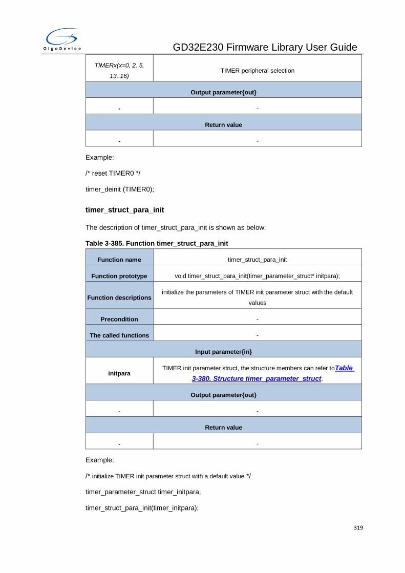
GD32E230 Firmware Library User Guide
319
TIMERx(x=0, 2, 5,
13..16) TIMER peripheral selection
Output parameter{out}
- -
Return value
- -
Example:
/* reset TIMER0 */
timer_deinit (TIMER0);
timer_struct_para_init
The description of timer_struct_para_init is shown as below:
Table 3-385. Function timer_struct_para_init
Function name timer_struct_para_init
Function prototype void timer_struct_para_init(timer_parameter_struct* initpara);
Function descriptions initialize the parameters of TIMER init parameter struct with the default
values
Precondition -
The called functions -
Input parameter{in}
initpara TIMER init parameter struct, the structure members can refer toTable
3-380. Structure timer_parameter_struct.
Output parameter{out}
- -
Return value
- -
Example:
/* initialize TIMER init parameter struct with a default value */
timer_parameter_struct timer_initpara;
timer_struct_para_init(timer_initpara);

GD32E230 Firmware Library User Guide
320
timer_init
The description of timer_init is shown as below:
Table 3-386. Function timer_init
Function name timer_init
Function prototype void timer_init(uint32_t timer_periph, timer_parameter_struct* initpara);
Function descriptions initialize TIMER counter
Precondition -
The called functions -
Input parameter{in}
timer_periph TIMER peripheral
TIMERx(x=0, 2, 5,
13..16) TIMER peripheral selection
Input parameter{in}
initpara
TIMER init parameter struct, the structure members can refer toTable
3-380. Structure timer_parameter_struct.
Output parameter{out}
- -
Return value
- -
Example:
/* initialize TIMER0 */
timer_parameter_struct timer_initpara;
timer_initpara.prescaler = 107;
timer_initpara.alignedmode = TIMER_COUNTER_EDGE;
timer_initpara.counterdirection = TIMER_COUNTER_UP;
timer_initpara.period = 999;
timer_initpara.clockdivision = TIMER_CKDIV_DIV1;
timer_initpara.repetitioncounter = 1;
timer_init(TIMER0,&timer_initpara);

GD32E230 Firmware Library User Guide
321
timer_enable
The description of timer_enable is shown as below:
Table 3-387. Function timer_enable
Function name timer_enable
Function prototype void timer_enable(uint32_t timer_periph);
Function descriptions enable a timer
Precondition -
The called functions -
Input parameter{in}
timer_periph TIMER peripheral
TIMERx(x=0, 2, 5,
13..16) TIMER peripheral selection
Output parameter{out}
- -
Return value
- -
Example:
/* enable TIMER0 */
timer_enable (TIMER0);
timer_disable
The description of timer_disable is shown as below:
Table 3-388. Function timer_disable
Function name timer_disable
Function prototype void timer_disable(uint32_t timer_periph);
Function descriptions disable a timer
Precondition -
The called functions -
Input parameter{in}
timer_periph TIMER peripheral

GD32E230 Firmware Library User Guide
322
TIMERx(x=0, 2, 5,
13..16) TIMER peripheral selection
Output parameter{out}
- -
Return value
- -
Example:
/* disable TIMER0 */
timer_disable (TIMER0);
timer_auto_reload_shadow_enable
The description of timer_auto_reload_shadow_enable is shown as below:
Table 3-389. Function timer_auto_reload_shadow_enable
Function name timer_auto_reload_shadow_enable
Function prototype void timer_auto_reload_shadow_enable(uint32_t timer_periph);
Function descriptions enable the auto reload shadow function
Precondition -
The called functions -
Input parameter{in}
timer_periph TIMER peripheral
TIMERx(x=0, 2, 5,
13..16) TIMER peripheral selection
Output parameter{out}
- -
Return value
- -
Example:
/* enable the TIMER0 auto reload shadow function */
timer_auto_reload_shadow_enable (TIMER0);

GD32E230 Firmware Library User Guide
323
timer_auto_reload_shadow_disable
The description of timer_auto_reload_shadow_disable is shown as below:
Table 3-390. Function timer_auto_reload_shadow_disable
Function name timer_auto_reload_shadow_ disable
Function prototype void timer_auto_reload_shadow_ disable (uint32_t timer_periph);
Function descriptions disable the auto reload shadow function
Precondition -
The called functions -
Input parameter{in}
timer_periph TIMER peripheral
TIMERx(x=0, 2, 5,
13..16) TIMER peripheral selection
Output parameter{out}
- -
Return value
- -
Example:
/* disable the TIMER0 auto reload shadow function */
timer_auto_reload_shadow_disable (TIMER0);
timer_update_event_enable
The description of timer_update_event_enable is shown as below:
Table 3-391. Function timer_update_event_enable
Function name timer_update_event_enable
Function prototype void timer_update_event_enable(uint32_t timer_periph);
Function descriptions enable the update event
Precondition -
The called functions -
Input parameter{in}
timer_periph TIMER peripheral
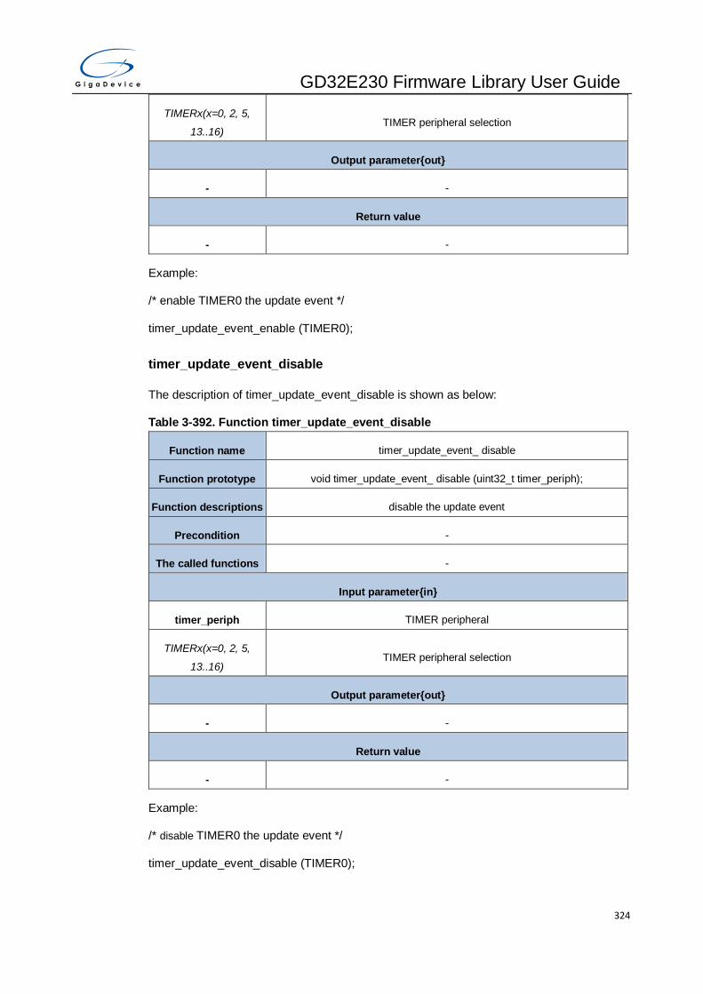
GD32E230 Firmware Library User Guide
324
TIMERx(x=0, 2, 5,
13..16) TIMER peripheral selection
Output parameter{out}
- -
Return value
- -
Example:
/* enable TIMER0 the update event */
timer_update_event_enable (TIMER0);
timer_update_event_disable
The description of timer_update_event_disable is shown as below:
Table 3-392. Function timer_update_event_disable
Function name timer_update_event_ disable
Function prototype void timer_update_event_ disable (uint32_t timer_periph);
Function descriptions disable the update event
Precondition -
The called functions -
Input parameter{in}
timer_periph TIMER peripheral
TIMERx(x=0, 2, 5,
13..16) TIMER peripheral selection
Output parameter{out}
- -
Return value
- -
Example:
/* disable TIMER0 the update event */
timer_update_event_disable (TIMER0);

GD32E230 Firmware Library User Guide
325
timer_counter_alignment
The description of timer_counter_alignment is shown as below:
Table 3-393. Function timer_counter_alignment
Function name timer_counter_alignment
Function prototype void timer_counter_alignment(uint32_t timer_periph, uint16_t aligned);
Function descriptions set TIMER counter alignment mode
Precondition -
The called functions -
Input parameter{in}
timer_periph TIMER peripheral
TIMERx(x=0, 2) TIMER peripheral selection
Input parameter{in}
aligned alignment mode
TIMER_COUNTER_ED
GE
No center-aligned mode (edge-aligned mode). The direction of the counter
isspecified by the DIR bit.
TIMER_COUNTER_CE
NTER_DOWN
Center-aligned and counting down assert mode. The counter counts under
center aligned and channel is configured in output mode (CHxMS=00 in
TIMERx_CHCTL0register). Only when the counter is counting down,
compare interrupt flag of channels can be set.
TIMER_COUNTER_CE
NTER_UP
Center-aligned and counting up assert mode. The counter counts under
center aligned and channel is configured in output mode (CHxMS=00 in
TIMERx_CHCTL0register). Only when the counter is counting up, compare
interrupt flag of channels can be set.
TIMER_COUNTER_CE
NTER_BOTH
Center-aligned and counting up/down assert mode. The counter counts
under center-aligned and channel is configured in output mode (CHxMS=00
in TIMERx_CHCTL0 register). Both when the counter is counting up and
counting down, compare interrupt flag of channels can be set.
Output parameter{out}
- -
Return value
- -
Example:

GD32E230 Firmware Library User Guide
326
/* set TIMER0 counter center-aligned and counting up assert mode */
timer_counter_alignment (TIMER0, TIMER_COUNTER_CENTER_UP);
timer_counter_up_direction
The description of timer_counter_up_direction is shown as below:
Table 3-394. Function timer_counter_up_direction
Function name timer_counter_up_direction
Function prototype void timer_counter_up_direction(uint32_t timer_periph);
Function descriptions set TIMER counter up direction
Precondition set TIMER counter no center-aligned mode (edge-aligned mode)
The called functions -
Input parameter{in}
timer_periph TIMER peripheral
TIMERx(x=0, 2) TIMER peripheral selection
Output parameter{out}
- -
Return value
- -
Example:
/* set TIMER0 counter up direction */
timer_counter_up_direction (TIMER0);
timer_counter_down_direction
The description of timer_counter_down_direction is shown as below:
Table 3-395. timer_counter_down_direction
Function name timer_counter_ down _direction
Function prototype void timer_counter_ down _direction(uint32_t timer_periph);
Function descriptions set TIMER counter down direction
Precondition set TIMER counter no center-aligned mode (edge-aligned mode)
The called functions -
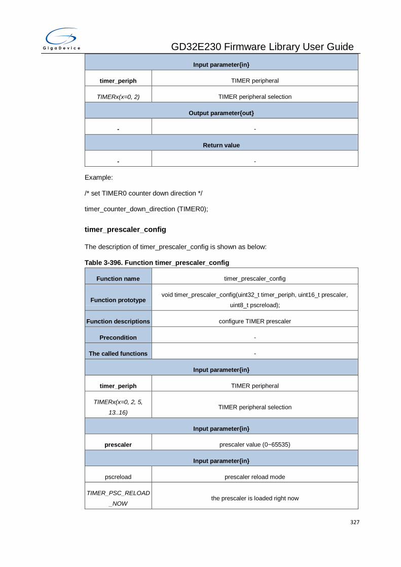
GD32E230 Firmware Library User Guide
327
Input parameter{in}
timer_periph TIMER peripheral
TIMERx(x=0, 2) TIMER peripheral selection
Output parameter{out}
- -
Return value
- -
Example:
/* set TIMER0 counter down direction */
timer_counter_down_direction (TIMER0);
timer_prescaler_config
The description of timer_prescaler_config is shown as below:
Table 3-396. Function timer_prescaler_config
Function name timer_prescaler_config
Function prototype void timer_prescaler_config(uint32_t timer_periph, uint16_t prescaler,
uint8_t pscreload);
Function descriptions configure TIMER prescaler
Precondition -
The called functions -
Input parameter{in}
timer_periph TIMER peripheral
TIMERx(x=0, 2, 5,
13..16) TIMER peripheral selection
Input parameter{in}
prescaler prescaler value (0~65535)
Input parameter{in}
pscreload prescaler reload mode
TIMER_PSC_RELOAD
_NOW the prescaler is loaded right now

GD32E230 Firmware Library User Guide
328
TIMER_PSC_RELOAD
_UPDATE the prescaler is loaded at the next update event
Output parameter{out}
- -
Return value
- -
Example:
/* configure TIMER0 prescaler */
timer_prescaler_config (TIMER0, 3000, TIMER_PSC_RELOAD_NOW);
timer_repetition_value_config
The description of timer_repetition_value_config is shown as below:
Table 3-397. Function timer_repetition_value_config
Function name timer_repetition_value_config
Function prototype void timer_repetition_value_config(uint32_t timer_periph, uint16_t
repetition);
Function descriptions configure TIMER repetition register value
Precondition -
The called functions -
Input parameter{in}
timer_periph TIMER peripheral
TIMERx(x=0,15,16) TIMER peripheral selection
Input parameter{in}
repetition the counter repetition value (0~255)
Output parameter{out}
- -
Return value
- -
Example:
/* configure TIMER0 repetition register value */

GD32E230 Firmware Library User Guide
329
timer_repetition_value_config (TIMER0, 98);
timer_autoreload_value_config
The description of timer_autoreload_value_config is shown as below:
Table 3-398. Function timer_autoreload_value_config
Function name timer_autoreload_value_config
Function prototype void timer_autoreload_value_config(uint32_t timer_periph, uint16_t
autoreload);
Function descriptions configure TIMER autoreload register value
Precondition -
The called functions -
Input parameter{in}
timer_periph TIMER peripheral
TIMERx(x=0, 2, 5,
13..16) TIMER peripheral selection
Input parameter{in}
autoreload the counter auto-reload value (0-65535)
Output parameter{out}
- -
Return value
- -
Example:
/* configure TIMER autoreload register value */
timer_autoreload_value_config (TIMER0, 3000);
timer_counter_value_config
The description of timer_counter_value_config is shown as below:
Table 3-399. Function timer_counter_value_config
Function name timer_counter_value_config
Function prototype void timer_counter_value_config(uint32_t timer_periph, uint16_t counter);
Function descriptions configure TIMER counter register value

GD32E230 Firmware Library User Guide
330
Precondition -
The called functions -
Input parameter{in}
timer_periph TIMER peripheral
TIMERx(x=0, 2, 5,
13..16) TIMER peripheral selection
Input parameter{in}
counter the counter value(0-65535)
Output parameter{out}
- -
Return value
- -
Example:
/* configure TIMER0 counter register value */
timer_counter_value_config (TIMER0, 3000);
timer_counter_read
The description of timer_counter_read is shown as below:
Table 3-400. Function timer_counter_read
Function name timer_counter_read
Function prototype uint32_t timer_counter_read(uint32_t timer_periph);
Function descriptions read TIMER counter value
Precondition -
The called functions -
Input parameter{in}
timer_periph TIMER peripheral
TIMERx(x=0, 2, 5,
13..16) TIMER peripheral selection
Output parameter{out}
- -

GD32E230 Firmware Library User Guide
331
Return value
uint32_t counter value(0~65535)
Example:
/* read TIMER0 counter value */
uint32_t i = 0;
i = timer_counter_read (TIMER0);
timer_prescaler_read
The description of timer_prescaler_read is shown as below:
Table 3-401. Function timer_prescaler_read
Function name timer_prescaler_read
Function prototype uint16_t timer_prescaler_read(uint32_t timer_periph);
Function descriptions read TIMER prescaler value
Precondition -
The called functions -
Input parameter{in}
timer_periph TIMER peripheral
TIMERx(x=0, 2, 5,
13..16) TIMER peripheral selection
Output parameter{out}
- -
Return value
uint16_t prescaler register value (0~65535)
Example:
/* read TIMER0 prescaler value */
uint16_t i = 0;
i = timer_prescaler_read (TIMER0);
timer_single_pulse_mode_config
The description of timer_single_pulse_mode_config is shown as below:
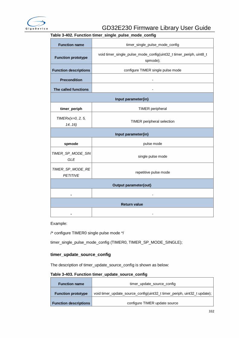
GD32E230 Firmware Library User Guide
332
Table 3-402. Function timer_single_pulse_mode_config
Function name timer_single_pulse_mode_config
Function prototype void timer_single_pulse_mode_config(uint32_t timer_periph, uint8_t
spmode);
Function descriptions configure TIMER single pulse mode
Precondition -
The called functions -
Input parameter{in}
timer_periph TIMER peripheral
TIMERx(x=0, 2, 5,
14..16) TIMER peripheral selection
Input parameter{in}
spmode pulse mode
TIMER_SP_MODE_SIN
GLE single pulse mode
TIMER_SP_MODE_RE
PETITIVE repetitive pulse mode
Output parameter{out}
- -
Return value
- -
Example:
/* configure TIMER0 single pulse mode */
timer_single_pulse_mode_config (TIMER0, TIMER_SP_MODE_SINGLE);
timer_update_source_config
The description of timer_update_source_config is shown as below:
Table 3-403. Function timer_update_source_config
Function name timer_update_source_config
Function prototype void timer_update_source_config(uint32_t timer_periph, uint32_t update);
Function descriptions configure TIMER update source
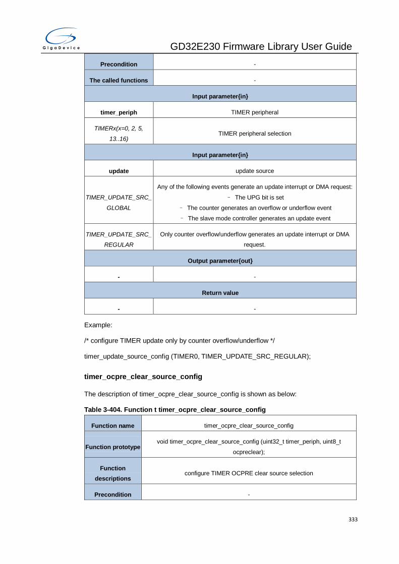
GD32E230 Firmware Library User Guide
333
Precondition -
The called functions -
Input parameter{in}
timer_periph TIMER peripheral
TIMERx(x=0, 2, 5,
13..16) TIMER peripheral selection
Input parameter{in}
update update source
TIMER_UPDATE_SRC_
GLOBAL
Any of the following events generate an update interrupt or DMA request:
– The UPG bit is set
– The counter generates an overflow or underflow event
– The slave mode controller generates an update event
TIMER_UPDATE_SRC_
REGULAR
Only counter overflow/underflow generates an update interrupt or DMA
request.
Output parameter{out}
- -
Return value
- -
Example:
/* configure TIMER update only by counter overflow/underflow */
timer_update_source_config (TIMER0, TIMER_UPDATE_SRC_REGULAR);
timer_ocpre_clear_source_config
The description of timer_ocpre_clear_source_config is shown as below:
Table 3-404. Function t timer_ocpre_clear_source_config
Function name timer_ocpre_clear_source_config
Function prototype void timer_ocpre_clear_source_config (uint32_t timer_periph, uint8_t
ocpreclear);
Function
descriptions configure TIMER OCPRE clear source selection
Precondition -
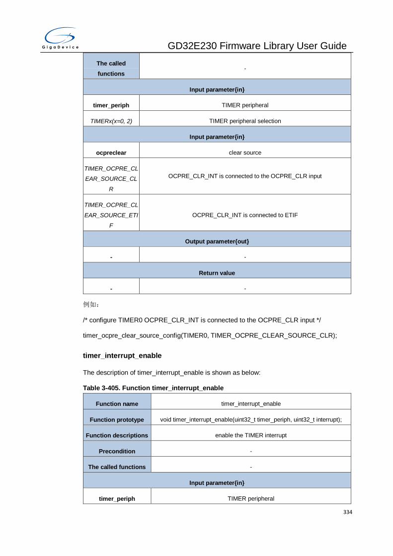
GD32E230 Firmware Library User Guide
334
The called
functions -
Input parameter{in}
timer_periph TIMER peripheral
TIMERx(x=0, 2) TIMER peripheral selection
Input parameter{in}
ocpreclear clear source
TIMER_OCPRE_CL
EAR_SOURCE_CL
R
OCPRE_CLR_INT is connected to the OCPRE_CLR input
TIMER_OCPRE_CL
EAR_SOURCE_ETI
F
OCPRE_CLR_INT is connected to ETIF
Output parameter{out}
- -
Return value
- -
例如:
/* configure TIMER0 OCPRE_CLR_INT is connected to the OCPRE_CLR input */
timer_ocpre_clear_source_config(TIMER0, TIMER_OCPRE_CLEAR_SOURCE_CLR);
timer_interrupt_enable
The description of timer_interrupt_enable is shown as below:
Table 3-405. Function timer_interrupt_enable
Function name timer_interrupt_enable
Function prototype void timer_interrupt_enable(uint32_t timer_periph, uint32_t interrupt);
Function descriptions enable the TIMER interrupt
Precondition -
The called functions -
Input parameter{in}
timer_periph TIMER peripheral

GD32E230 Firmware Library User Guide
335
TIMERx please refer to the following parameters
Input parameter{in}
interrupt timer interrupt enable source
TIMER_INT_UP update interrupt enable, TIMERx (x=0, 2, 5, 13..16)
TIMER_INT_CH0 channel 0 interrupt enable, TIMERx(x=0, 2, 13..16)
TIMER_INT_CH1 channel 1 interrupt enable, TIMERx(x=0, 2, 14)
TIMER_INT_CH2 channel 2 interrupt enable, TIMERx(x=0, 2)
TIMER_INT_CH3 channel 3 interrupt enable , TIMERx(x=0, 2)
TIMER_INT_CMT commutation interrupt enable, TIMERx (x=0, 14..16)
TIMER_INT_TRG trigger interrupt enable, TIMERx(x=0, 2, 14)
TIMER_INT_BRK break interrupt enable, TIMERx (x=0, 14..16)
Output parameter{out}
- -
Return value
- -
Example:
/* enable the TIMER0 update interrupt */
timer_interrupt_enable (TIMER0, TIMER_INT_UP);
timer_interrupt_disable
The description of timer_interrupt_disable is shown as below:
Table 3-406. Function timer_interrupt_disable
Function name timer_interrupt_ disable
Function prototype void timer_interrupt_ disable (uint32_t timer_periph, uint32_t interrupt);
Function descriptions disable the TIMER interrupt
Precondition -
The called functions -
Input parameter{in}
timer_periph TIMER peripheral

GD32E230 Firmware Library User Guide
336
TIMERx please refer to the following parameters
Input parameter{in}
interrupt timer interrupt disable source
TIMER_INT_UP update interrupt disable, TIMERx (x=0, 2, 5, 13..16)
TIMER_INT_CH0 channel 0 interrupt disable, TIMERx(x=0, 2, 13..16)
TIMER_INT_CH1 channel 1 interrupt disable, TIMERx(x=0, 2, 14)
TIMER_INT_CH2 channel 2 interrupt disable, TIMERx(x=0, 2)
TIMER_INT_CH3 channel 3 interrupt disable, TIMERx(x=0, 2)
TIMER_INT_CMT commutation interrupt disable, TIMERx (x=0, 14..16)
TIMER_INT_TRG trigger interrupt disable, TIMERx(x=0, 2, 14)
TIMER_INT_BRK break interrupt disable, TIMERx(x=0, 14..16)
Output parameter{out}
- -
Return value
- -
Example:
/* disable the TIMER0 update interrupt */
timer_interrupt_disable (TIMER0, TIMER_INT_UP);
timer_interrupt_flag_get
The description of timer_interrupt_flag_get is shown as below:
Table 3-407. Function timer_interrupt_flag_get
Function name timer_interrupt_flag_get
Function prototype FlagStatus timer_interrupt_flag_get(uint32_t timer_periph, uint32_t
interrupt);
Function descriptions get timer interrupt flag
Precondition -
The called functions -
Input parameter{in}

GD32E230 Firmware Library User Guide
337
timer_periph TIMER peripheral
TIMERx please refer to the following parameters
Input parameter{in}
interrupt the timer interrupt bits
TIMER_INT_FLAG_UP update interrupt flag,TIMERx(x=0, 2, 5, 13..16)
TIMER_INT_FLAG_CH0 channel 0 interrupt flag,TIMERx(x=0, 2, 13..16)
TIMER_INT_FLAG_CH1 channel 1 interrupt flag,TIMERx(x=0, 2, 14)
TIMER_INT_FLAG_CH2 channel 2 interrupt flag,TIMERx TIMERx(x=0, 2)
TIMER_INT_FLAG_CH3 channel 3 interrupt flag,TIMERx TIMERx(x=0, 2)
TIMER_INT_FLAG_CM
T
channel commutation interrupt flag, TIMERx (x=0, 14..16)
TIMER_INT_FLAG_TRG trigger interrupt flag, TIMERx(x=0, 2, 14)
TIMER_INT_FLAG_BRK break interrupt flag, TIMERx(x=0, 14..16)
Output parameter{out}
- -
Return value
FlagStatus SET or RESET
Example:
/* get TIMER0 update interrupt flag */
FlagStatus Flag_ interrupt = RESET;
Flag_ interrupt = timer_interrupt_flag_get (TIMER0, TIMER_INT_FLAG_UP);
timer_interrupt_flag_clear
The description of timer_interrupt_flag_clear is shown as below:
Table 3-408. Function timer_interrupt_flag_clear
Function name timer_interrupt_flag_clear
Function prototype void timer_interrupt_flag_clear(uint32_t timer_periph, uint32_t interrupt);
Function descriptions clear TIMER interrupt flag
Precondition -

GD32E230 Firmware Library User Guide
338
The called functions -
Input parameter{in}
timer_periph TIMER peripheral
TIMERx please refer to the following parameters
Input parameter{in}
interrupt the timer interrupt bits
TIMER_INT_FLAG_UP update interrupt flag,TIMERx(x=0, 2, 5, 13..16)
TIMER_INT_FLAG_CH0 channel 0 interrupt flag,TIMERx(x=0, 2, 13..16)
TIMER_INT_FLAG_CH1 channel 1 interrupt flag,TIMERx(x=0, 2, 14)
TIMER_INT_FLAG_CH2 channel 2 interrupt flag,TIMERx TIMERx(x=0, 2)
TIMER_INT_FLAG_CH3 channel 3 interrupt flag,TIMERx TIMERx(x=0, 2)
TIMER_INT_FLAG_CM
T
channel commutation interrupt flag, TIMERx (x=0, 14..16)
TIMER_INT_FLAG_TRG trigger interrupt flag, TIMERx(x=0, 2, 14)
TIMER_INT_FLAG_BRK break interrupt flag, TIMERx(x=0, 14..16)
Output parameter{out}
- -
Return value
- -
Example:
/* clear TIMER0 update interrupt flag */
timer_interrupt_flag_clear (TIMER0, TIMER_INT_FLAG_UP);
timer_flag_get
The description of timer_flag_get is shown as below:
Table 3-409. Function timer_flag_get
Function name timer_flag_get
Function prototype FlagStatus timer_flag_get(uint32_t timer_periph, uint32_t flag);
Function descriptions get TIMER flags

GD32E230 Firmware Library User Guide
339
Precondition -
The called functions -
Input parameter{in}
timer_periph TIMER peripheral
TIMERx please refer to the following parameters
Input parameter{in}
flag the timer interrupt flags
TIMER_FLAG_UP update flag,TIMERx(x=0, 2, 5, 13..16)
TIMER_FLAG_CH0 channel 0 flag, TIMERx(x=0, 2, 13..16)
TIMER_FLAG_CH1 channel 1 flag, TIMERx(x=0, 2, 14)
TIMER_FLAG_CH2 channel 2 flag, TIMERx(x=0, 2)
TIMER_FLAG_CH3 channel 3 flag, TIMERx(x=0, 2)
TIMER_FLAG_CMT channel commutation flag, TIMERx(x=0, 14..16)
TIMER_FLAG_TRG trigger flag, TIMERx(x=0, 2, 14)
TIMER_FLAG_BRK break flag, TIMERx(x=0, 14..16)
TIMER_FLAG_CH0O channel 0 overcapture flag, TIMERx(x=0, 2, 3..16)
TIMER_FLAG_CH1O channel 1 overcapture flag, TIMERx(x=0, 2, 14)
TIMER_FLAG_CH2O channel 2 overcapture flag, TIMERx(x=0, 2)
TIMER_FLAG_CH3O channel 3 overcapture flag, TIMERx(x=0, 2)
Output parameter{out}
- -
Return value
FlagStatus SET or RESET
Example:
/* get TIMER0 update flags */
FlagStatus Flag_status = RESET;
Flag_status = timer_flag_get (TIMER0, TIMER_FLAG_UP);

GD32E230 Firmware Library User Guide
340
timer_flag_clear
The description of timer_flag_clear is shown as below:
Table 3-410. Function timer_flag_clear
Function name timer_flag_clear
Function prototype void timer_flag_clear(uint32_t timer_periph, uint32_t flag);
Function descriptions clear TIMER flags
Precondition -
The called functions -
Input parameter{in}
timer_periph TIMER peripheral
TIMERx please refer to the following parameters
Input parameter{in}
flag the timer interrupt flags
TIMER_FLAG_UP update flag,TIMERx(x=0, 2, 5, 13..16)
TIMER_FLAG_CH0 channel 0 flag, TIMERx(x=0, 2, 13..16)
TIMER_FLAG_CH1 channel 1 flag, TIMERx(x=0, 2, 14)
TIMER_FLAG_CH2 channel 2 flag, TIMERx(x=0, 2)
TIMER_FLAG_CH3 channel 3 flag, TIMERx(x=0, 2)
TIMER_FLAG_CMT channel commutation flag, TIMERx(x=0, 14..16)
TIMER_FLAG_TRG trigger flag, TIMERx(x=0, 2, 14)
TIMER_FLAG_BRK break flag, TIMERx(x=0, 14..16)
TIMER_FLAG_CH0O channel 0 overcapture flag, TIMERx(x=0, 2, 13..16)
TIMER_FLAG_CH1O channel 1 overcapture flag, TIMERx(x=0, 2, 14)
TIMER_FLAG_CH2O channel 2 overcapture flag, TIMERx(x=0, 2)
TIMER_FLAG_CH3O channel 3 overcapture flag, TIMERx(x=0, 2)
Output parameter{out}
- -
Return value

GD32E230 Firmware Library User Guide
341
- -
Example:
/* clear TIMER0 update flags */
timer_flag_clear (TIMER0, TIMER_FLAG_UP);
timer_dma_enable
The description of timer_dma_enable is shown as below:
Table 3-411. Function timer_dma_enable
Function name timer_dma_enable
Function prototype void timer_dma_enable(uint32_t timer_periph, uint16_t dma);
Function descriptions enable the TIMER DMA
Precondition -
The called functions -
Input parameter{in}
timer_periph TIMER peripheral
TIMERx please refer to the following parameters
Input parameter{in}
dma timer DMA source enable
TIMER_DMA_UPD update DMA enable, TIMERx(x=0, 2, 5, 14..16)
TIMER_DMA_CH0D channel 0 DMA enable, TIMERx(x=0, 2, 14..16)
TIMER_DMA_CH1D channel 1 DMA enable, TIMERx(x=0..2, 4)
TIMER_DMA_CH2D channel 2 DMA enable, TIMERx(x=0, 2)
TIMER_DMA_CH3D channel 3 DMA enable, TIMERx(x=0, 2)
TIMER_DMA_CMTD commutation DMA request enable, TIMERx(x=0, 14)
TIMER_DMA_TRGD trigger DMA enable, TIMERx(x=0..2, 14)
Output parameter{out}
- -
Return value
- -
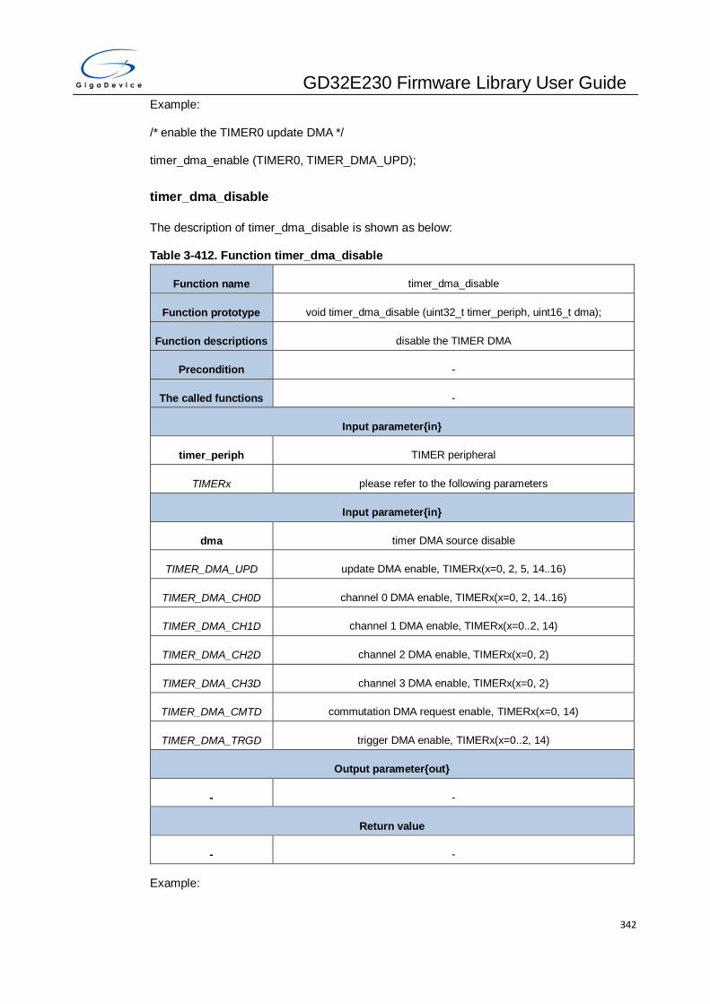
GD32E230 Firmware Library User Guide
342
Example:
/* enable the TIMER0 update DMA */
timer_dma_enable (TIMER0, TIMER_DMA_UPD);
timer_dma_disable
The description of timer_dma_disable is shown as below:
Table 3-412. Function timer_dma_disable
Function name timer_dma_disable
Function prototype void timer_dma_disable (uint32_t timer_periph, uint16_t dma);
Function descriptions disable the TIMER DMA
Precondition -
The called functions -
Input parameter{in}
timer_periph TIMER peripheral
TIMERx please refer to the following parameters
Input parameter{in}
dma timer DMA source disable
TIMER_DMA_UPD update DMA enable, TIMERx(x=0, 2, 5, 14..16)
TIMER_DMA_CH0D channel 0 DMA enable, TIMERx(x=0, 2, 14..16)
TIMER_DMA_CH1D channel 1 DMA enable, TIMERx(x=0..2, 14)
TIMER_DMA_CH2D channel 2 DMA enable, TIMERx(x=0, 2)
TIMER_DMA_CH3D channel 3 DMA enable, TIMERx(x=0, 2)
TIMER_DMA_CMTD commutation DMA request enable, TIMERx(x=0, 14)
TIMER_DMA_TRGD trigger DMA enable, TIMERx(x=0..2, 14)
Output parameter{out}
- -
Return value
- -
Example:
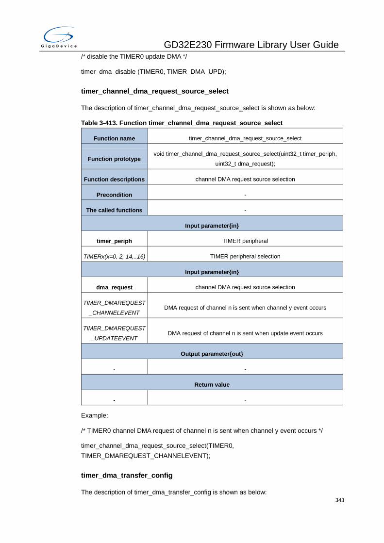
GD32E230 Firmware Library User Guide
343
/* disable the TIMER0 update DMA */
timer_dma_disable (TIMER0, TIMER_DMA_UPD);
timer_channel_dma_request_source_select
The description of timer_channel_dma_request_source_select is shown as below:
Table 3-413. Function timer_channel_dma_request_source_select
Function name timer_channel_dma_request_source_select
Function prototype void timer_channel_dma_request_source_select(uint32_t timer_periph,
uint32_t dma_request);
Function descriptions channel DMA request source selection
Precondition -
The called functions -
Input parameter{in}
timer_periph TIMER peripheral
TIMERx(x=0, 2, 14,..16) TIMER peripheral selection
Input parameter{in}
dma_request channel DMA request source selection
TIMER_DMAREQUEST
_CHANNELEVENT DMA request of channel n is sent when channel y event occurs
TIMER_DMAREQUEST
_UPDATEEVENT DMA request of channel n is sent when update event occurs
Output parameter{out}
- -
Return value
- -
Example:
/* TIMER0 channel DMA request of channel n is sent when channel y event occurs */
timer_channel_dma_request_source_select(TIMER0,
TIMER_DMAREQUEST_CHANNELEVENT);
timer_dma_transfer_config
The description of timer_dma_transfer_config is shown as below:
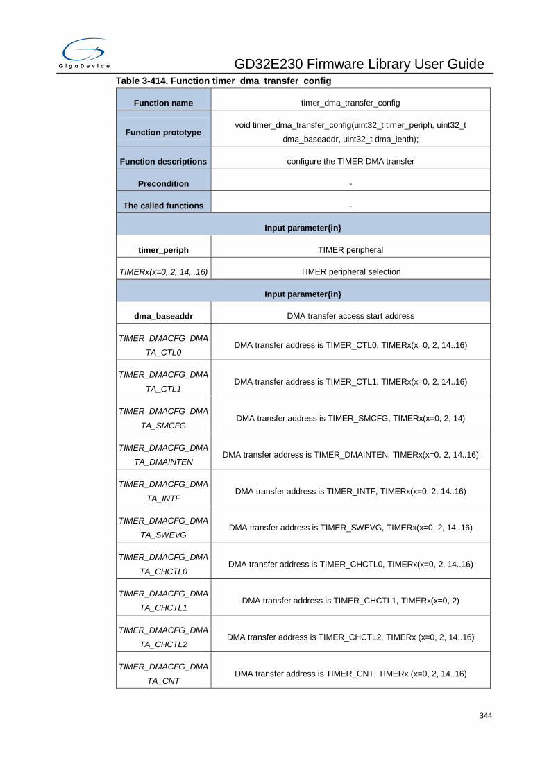
GD32E230 Firmware Library User Guide
344
Table 3-414. Function timer_dma_transfer_config
Function name timer_dma_transfer_config
Function prototype void timer_dma_transfer_config(uint32_t timer_periph, uint32_t
dma_baseaddr, uint32_t dma_lenth);
Function descriptions configure the TIMER DMA transfer
Precondition -
The called functions -
Input parameter{in}
timer_periph TIMER peripheral
TIMERx(x=0, 2, 14,..16) TIMER peripheral selection
Input parameter{in}
dma_baseaddr DMA transfer access start address
TIMER_DMACFG_DMA
TA_CTL0 DMA transfer address is TIMER_CTL0, TIMERx(x=0, 2, 14..16)
TIMER_DMACFG_DMA
TA_CTL1 DMA transfer address is TIMER_CTL1, TIMERx(x=0, 2, 14..16)
TIMER_DMACFG_DMA
TA_SMCFG DMA transfer address is TIMER_SMCFG, TIMERx(x=0, 2, 14)
TIMER_DMACFG_DMA
TA_DMAINTEN DMA transfer address is TIMER_DMAINTEN, TIMERx(x=0, 2, 14..16)
TIMER_DMACFG_DMA
TA_INTF DMA transfer address is TIMER_INTF, TIMERx(x=0, 2, 14..16)
TIMER_DMACFG_DMA
TA_SWEVG DMA transfer address is TIMER_SWEVG, TIMERx(x=0, 2, 14..16)
TIMER_DMACFG_DMA
TA_CHCTL0 DMA transfer address is TIMER_CHCTL0, TIMERx(x=0, 2, 14..16)
TIMER_DMACFG_DMA
TA_CHCTL1 DMA transfer address is TIMER_CHCTL1, TIMERx(x=0, 2)
TIMER_DMACFG_DMA
TA_CHCTL2 DMA transfer address is TIMER_CHCTL2, TIMERx (x=0, 2, 14..16)
TIMER_DMACFG_DMA
TA_CNT DMA transfer address is TIMER_CNT, TIMERx (x=0, 2, 14..16)

GD32E230 Firmware Library User Guide
345
TIMER_DMACFG_DMA
TA_PSC DMA transfer address is TIMER_PSC, TIMERx (x=0, 2, 14..16)
TIMER_DMACFG_DMA
TA_CAR MA transfer address is TIMER_CAR, TIMERx (x=0, 2, 14..16)
TIMER_DMACFG_DMA
TA_CREP DMA transfer address is TIMER_CREP, TIMERx (x=0, 14..16)
TIMER_DMACFG_DMA
TA_CH0CV DMA transfer address is TIMER_CH0CV, TIMERx (x=0, 2, 14..16)
TIMER_DMACFG_DMA
TA_CH1CV DMA transfer address is TIMER_CH1CV, TIMERx(x=0, 2, 14)
TIMER_DMACFG_DMA
TA_CH2CV DMA transfer address is TIMER_CH2CV, TIMERx(x=0, 2)
TIMER_DMACFG_DMA
TA_CH3CV DMA transfer address is TIMER_CH3CV, TIMERx(x=0, 2)
TIMER_DMACFG_DMA
TA_CCHP DMA transfer address is TIMER_CCHP, TIMERx (x=0, 14..16)
TIMER_DMACFG_DMA
TA_DMACFG DMA transfer address is TIMER_DMACFG, TIMERx (x=0, 2, 14..16)
Input parameter{in}
dma_lenth DMA transfer count
TIMER_DMACFG_DMA
TC_xTRANSFER
x=1..18, DMA transfer x time
Output parameter{out}
- -
Return value
- -
Example:
/* configure the TIMER0 DMA transfer */
timer_dma_transfer_config(TIMER0, TIMER_DMACFG_DMATA_CTL0,
TIMER_DMACFG_DMATC_5TRANSFER);
timer_event_software_generate
The description of timer_event_software_generate is shown as below:
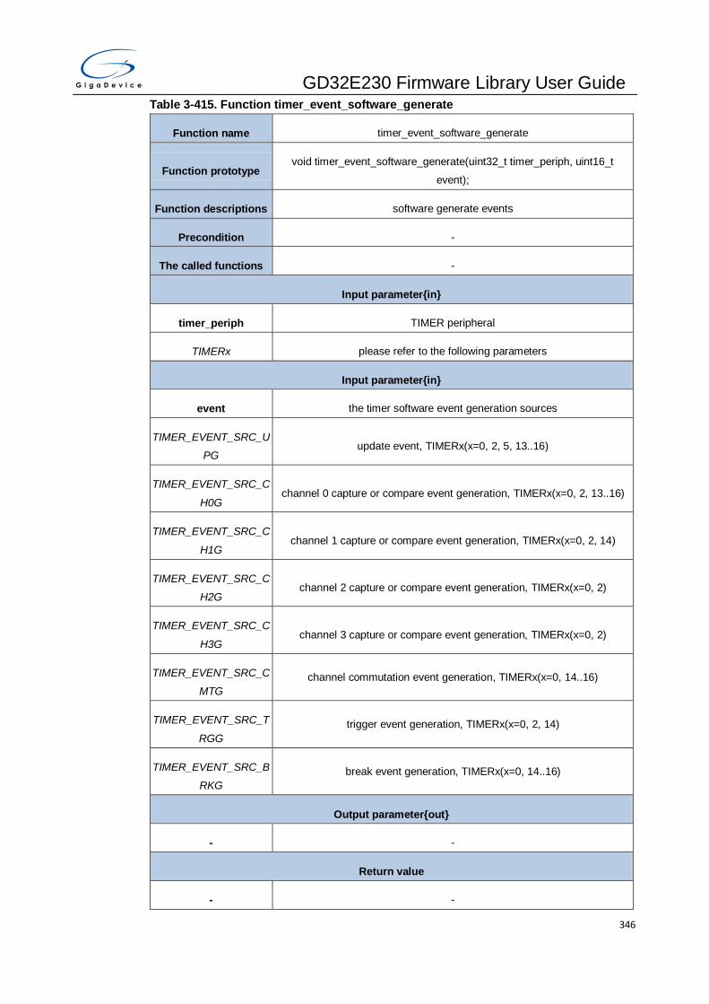
GD32E230 Firmware Library User Guide
346
Table 3-415. Function timer_event_software_generate
Function name timer_event_software_generate
Function prototype void timer_event_software_generate(uint32_t timer_periph, uint16_t
event);
Function descriptions software generate events
Precondition -
The called functions -
Input parameter{in}
timer_periph TIMER peripheral
TIMERx please refer to the following parameters
Input parameter{in}
event the timer software event generation sources
TIMER_EVENT_SRC_U
PG update event, TIMERx(x=0, 2, 5, 13..16)
TIMER_EVENT_SRC_C
H0G channel 0 capture or compare event generation, TIMERx(x=0, 2, 13..16)
TIMER_EVENT_SRC_C
H1G channel 1 capture or compare event generation, TIMERx(x=0, 2, 14)
TIMER_EVENT_SRC_C
H2G channel 2 capture or compare event generation, TIMERx(x=0, 2)
TIMER_EVENT_SRC_C
H3G channel 3 capture or compare event generation, TIMERx(x=0, 2)
TIMER_EVENT_SRC_C
MTG
channel commutation event generation, TIMERx(x=0, 14..16)
TIMER_EVENT_SRC_T
RGG
trigger event generation, TIMERx(x=0, 2, 14)
TIMER_EVENT_SRC_B
RKG
break event generation, TIMERx(x=0, 14..16)
Output parameter{out}
- -
Return value
- -
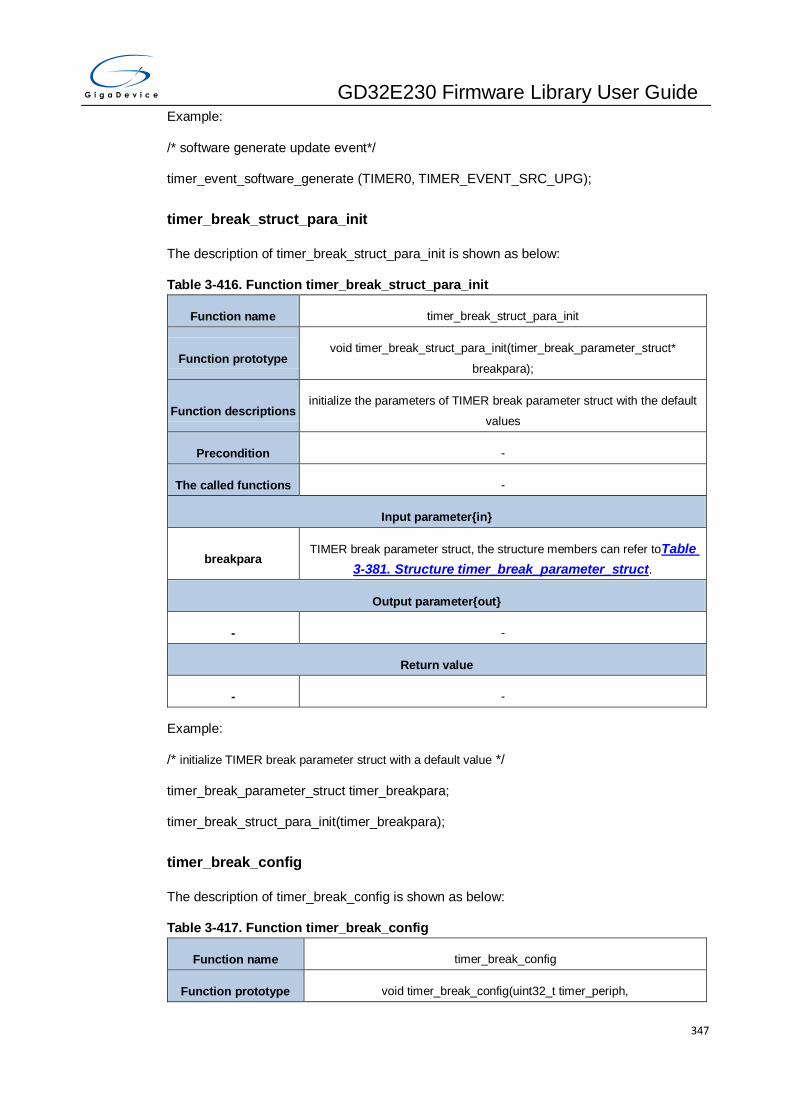
GD32E230 Firmware Library User Guide
347
Example:
/* software generate update event*/
timer_event_software_generate (TIMER0, TIMER_EVENT_SRC_UPG);
timer_break_struct_para_init
The description of timer_break_struct_para_init is shown as below:
Table 3-416. Function timer_break_struct_para_init
Function name timer_break_struct_para_init
Function prototype void timer_break_struct_para_init(timer_break_parameter_struct*
breakpara);
Function descriptions initialize the parameters of TIMER break parameter struct with the default
values
Precondition -
The called functions -
Input parameter{in}
breakpara TIMER break parameter struct, the structure members can refer toTable
3-381. Structure timer_break_parameter_struct.
Output parameter{out}
- -
Return value
- -
Example:
/* initialize TIMER break parameter struct with a default value */
timer_break_parameter_struct timer_breakpara;
timer_break_struct_para_init(timer_breakpara);
timer_break_config
The description of timer_break_config is shown as below:
Table 3-417. Function timer_break_config
Function name timer_break_config
Function prototype void timer_break_config(uint32_t timer_periph,

GD32E230 Firmware Library User Guide
348
timer_break_parameter_struct* breakpara);
Function descriptions configure TIMER break function
Precondition -
The called functions -
Input parameter{in}
timer_periph TIMER peripheral
TIMERx(x=0, 14..16) TIMER peripheral selection
Input parameter{in}
breakpara TIMER break parameter struct, the structure members can refer toTable
3-381. Structure timer_break_parameter_struct.
Output parameter{out}
- -
Return value
- -
Example:
/* configure TIMER0 break function */
timer_break_parameter_struct timer_breakpara;
timer_breakpara.runoffstate = TIMER_ROS_STATE_DISABLE;
timer_breakpara.ideloffstate = TIMER_IOS_STATE_DISABLE ;
timer_breakpara.deadtime = 255;
timer_breakpara.breakpolarity = TIMER_BREAK_POLARITY_LOW;
timer_breakpara.outputautostate = TIMER_OUTAUTO_ENABLE;
timer_breakpara.protectmode = TIMER_CCHP_PROT_0;
timer_breakpara.breakstate = TIMER_BREAK_ENABLE;
timer_break_config(TIMER0, &timer_breakpara);
timer_break_enable
The description of timer_break_enable is shown as below:
Table 3-418. Function timer_break_enable
Function name timer_break_enable

GD32E230 Firmware Library User Guide
349
Function prototype void timer_break_enable(uint32_t timer_periph);
Function descriptions enable TIMER break function
Precondition This function can be called only when PROT [1:0] bit-filed in
TIMERx_CCHP register is 00.
The called functions -
Input parameter{in}
timer_periph TIMER peripheral
TIMERx(x=0, 14..16) TIMER peripheral selection
Output parameter{out}
- -
Return value
- -
Example:
/* enable TIMER0 break function*/
timer_break_enable (TIMER0);
timer_break_disable
The description of timer_break_disable is shown as below:
Table 3-419. Function timer_break_disable
Function name timer_break_disable
Function prototype void timer_break_disable(uint32_t timer_periph);
Function descriptions disable TIMER break function
Precondition This function can be called only when PROT [1:0] bit-filed in
TIMERx_CCHP register is 00.
The called functions -
Input parameter{in}
timer_periph TIMER peripheral
TIMERx(x=0, 14..16) TIMER peripheral selection
Output parameter{out}
- -
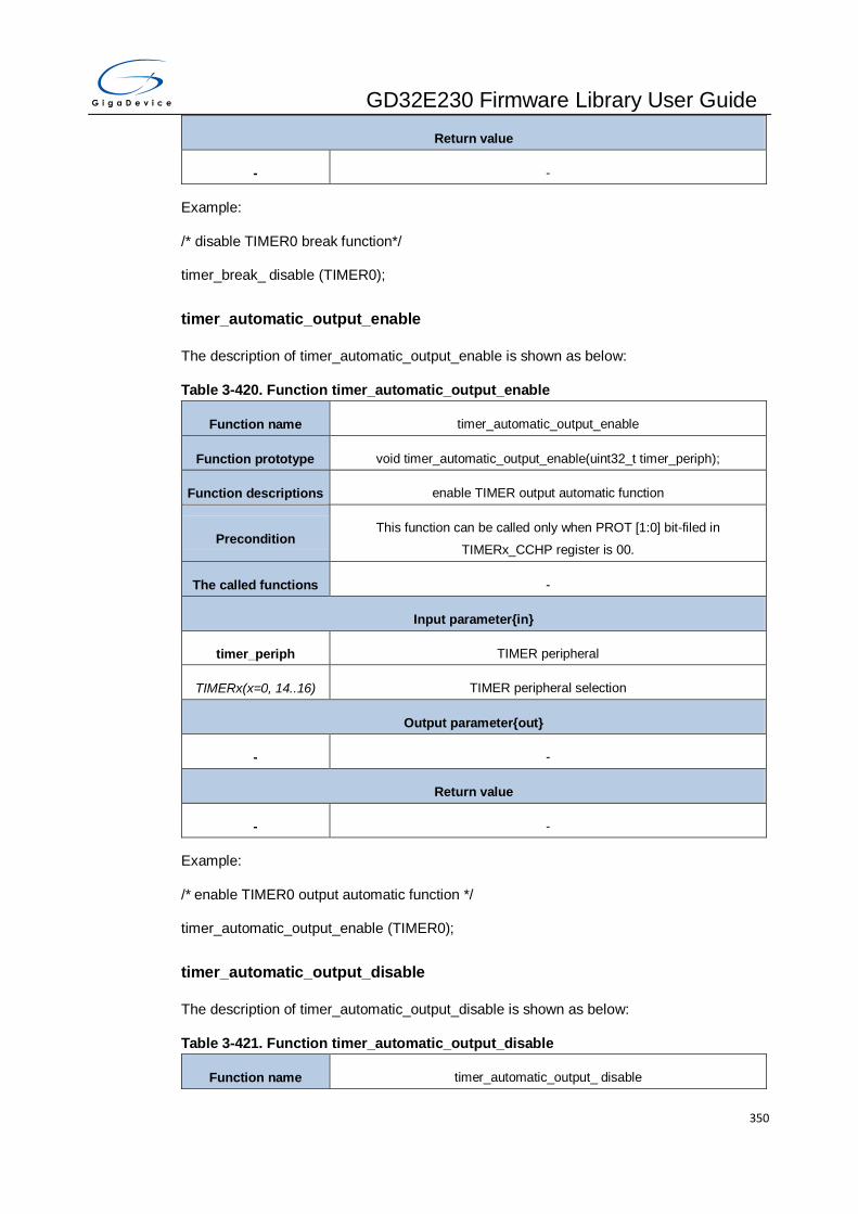
GD32E230 Firmware Library User Guide
350
Return value
- -
Example:
/* disable TIMER0 break function*/
timer_break_ disable (TIMER0);
timer_automatic_output_enable
The description of timer_automatic_output_enable is shown as below:
Table 3-420. Function timer_automatic_output_enable
Function name timer_automatic_output_enable
Function prototype void timer_automatic_output_enable(uint32_t timer_periph);
Function descriptions enable TIMER output automatic function
Precondition This function can be called only when PROT [1:0] bit-filed in
TIMERx_CCHP register is 00.
The called functions -
Input parameter{in}
timer_periph TIMER peripheral
TIMERx(x=0, 14..16) TIMER peripheral selection
Output parameter{out}
- -
Return value
- -
Example:
/* enable TIMER0 output automatic function */
timer_automatic_output_enable (TIMER0);
timer_automatic_output_disable
The description of timer_automatic_output_disable is shown as below:
Table 3-421. Function timer_automatic_output_disable
Function name timer_automatic_output_ disable

GD32E230 Firmware Library User Guide
351
Function prototype void timer_automatic_output_ disable (uint32_t timer_periph);
Function descriptions disable TIMER output automatic function
Precondition This function can be called only when PROT [1:0] bit-filed in
TIMERx_CCHP register is 00.
The called functions -
Input parameter{in}
timer_periph TIMER peripheral
TIMERx(x=0, 14..16) TIMER peripheral selection
Output parameter{out}
- -
Return value
- -
Example:
/* disable TIMER0 output automatic function */
timer_automatic_output_disable (TIMER0);
timer_primary_output_config
The description of timer_primary_output_config is shown as below:
Table 3-422. Function timer_primary_output_config
Function name timer_primary_output_config
Function prototype void timer_primary_output_config(uint32_t timer_periph, ControlStatus
newvalue);
Function descriptions configure TIMER primary output function
Precondition -
The called functions -
Input parameter{in}
timer_periph TIMER peripheral
TIMERx(x=0,14..16) TIMER peripheral selection
Input parameter{in}
newvalue control value

GD32E230 Firmware Library User Guide
352
ENABLE enable function
DISABLE disable function
Output parameter{out}
- -
Return value
- -
Example:
/* enable TIMER0 primary output function */
timer_primary_output_config (TIMER0, ENABLE);
timer_channel_control_shadow_config
The description of timer_channel_control_shadow_config is shown as below:
Table 3-423. Function timer_channel_control_shadow_config
Function name timer_channel_control_shadow_config
Function prototype void timer_channel_control_shadow_config(uint32_t timer_periph,
ControlStatus newvalue);
Function descriptions channel commutation control shadow register enable
Precondition -
The called functions -
Input parameter{in}
timer_periph TIMER peripheral
TIMERx(x=0, 14..16) TIMER peripheral selection
Input parameter{in}
newvalue control value
ENABLE enable function
DISABLE disable function
Output parameter{out}
- -
Return value

GD32E230 Firmware Library User Guide
353
- -
Example:
/* channel capture/compare control shadow register enable */
timer_channel_control_shadow_config (TIMER0, ENABLE);
timer_channel_control_shadow_update_config
The description of timer_channel_control_shadow_update_config is shown as below:
Table 3-424. Function timer_channel_control_shadow_update_config
Function name timer_channel_control_shadow_update_config
Function prototype void timer_channel_control_shadow_update_config(uint32_t timer_periph,
uint8_t ccuctl);
Function descriptions configure commutation control shadow register update control
Precondition -
The called functions -
Input parameter{in}
timer_periph TIMER peripheral
TIMERx(x=0, 14..16) TIMER peripheral selection
Input parameter{in}
ccuctl channel control shadow register update control
TIMER_UPDATECTL_C
CU the shadow registers update by when CMTG bit is set
TIMER_UPDATECTL_C
CUTRI
the shadow registers update by when CMTG bit is set or an rising edge of
TRGI occurs
Output parameter{out}
- -
Return value
- -
Example:
/* configure TIMER0 channel control shadow register update when CMTG bit is set */
timer_channel_control_shadow_update_config (TIMER0, TIMER_UPDATECTL_CCU);
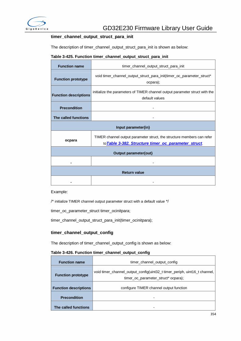
GD32E230 Firmware Library User Guide
354
timer_channel_output_struct_para_init
The description of timer_channel_output_struct_para_init is shown as below:
Table 3-425. Function timer_channel_output_struct_para_init
Function name timer_channel_output_struct_para_init
Function prototype void timer_channel_output_struct_para_init(timer_oc_parameter_struct*
ocpara);
Function descriptions initialize the parameters of TIMER channel output parameter struct with the
default values
Precondition -
The called functions -
Input parameter{in}
ocpara TIMER channel output parameter struct, the structure members can refer
toTable 3-382. Structure timer_oc_parameter_struct.
Output parameter{out}
- -
Return value
- -
Example:
/* initialize TIMER channel output parameter struct with a default value */
timer_oc_parameter_struct timer_ocinitpara;
timer_channel_output_struct_para_init(timer_ocinitpara);
timer_channel_output_config
The description of timer_channel_output_config is shown as below:
Table 3-426. Function timer_channel_output_config
Function name timer_channel_output_config
Function prototype void timer_channel_output_config(uint32_t timer_periph, uint16_t channel,
timer_oc_parameter_struct* ocpara);
Function descriptions configure TIMER channel output function
Precondition -
The called functions -

GD32E230 Firmware Library User Guide
355
Input parameter{in}
timer_periph TIMER peripheral
TIMERx please refer to the following parameters
Input parameter{in}
channel channel to be configured
TIMER_CH_0 TIMER channel 0 (TIMERx(x=0, 2, 13..16))
TIMER_CH_1 TIMER channel 1 (TIMERx(x=0, 2, 14))
TIMER_CH_2 TIMER channel 2 (TIMERx(x=0, 2))
TIMER_CH_3 IMER channel 3 (TIMERx(x=0, 2))
Input parameter{in}
ocpara TIMER channel output parameter struct, the structure members can refer
toTable 3-382. Structure timer_oc_parameter_struct.
Output parameter{out}
- -
Return value
- -
Example:
/* configure TIMER0 channel 0 output function */
timer_oc_parameter_struct timer_ocinitpara;
timer_ocinitpara.outputstate = TIMER_CCX_ENABLE;
timer_ocinitpara.outputnstate = TIMER_CCXN_ENABLE;
timer_ocinitpara.ocpolarity = TIMER_OC_POLARITY_HIGH;
timer_ocinitpara.ocnpolarity = TIMER_OCN_POLARITY_HIGH;
timer_ocinitpara.ocidlestate = TIMER_OC_IDLE_STATE_HIGH;
timer_ocinitpara.ocnidlestate = TIMER_OCN_IDLE_STATE_LOW;
timer_channel_output_config(TIMER0, TIMER_CH_0, &timer_ocinitpara);
timer_channel_output_mode_config
The description of timer_channel_output_mode_config is shown as below:

GD32E230 Firmware Library User Guide
356
Table 3-427. Function timer_channel_output_mode_config
Function name timer_channel_output_mode_config
Function prototype void timer_channel_output_mode_config(uint32_t timer_periph, uint16_t
channel, uint16_t ocmode);
Function descriptions configure TIMER channel output compare mode
Precondition -
The called functions -
Input parameter{in}
timer_periph TIMER peripheral
TIMERx please refer to the following parameters
Input parameter{in}
channel channel to be configured
TIMER_CH_0 TIMER channel 0 (TIMERx (x=0, 2, 13..16))
TIMER_CH_1 TIMER channel 1 (TIMERx (x=0, 2, 14))
TIMER_CH_2 TIMER channel 2 (TIMERx (x=0, 2))
TIMER_CH_3 IMER channel 3 (TIMERx (x=0, 2))
Input parameter{in}
ocmode channel output compare mode
TIMER_OC_MODE_TIM
ING timing mode
TIMER_OC_MODE_AC
TIVE set the channel output
TIMER_OC_MODE_INA
CTIVE clear the channel output
TIMER_OC_MODE_TO
GGLE toggle on match
TIMER_OC_MODE_LO
W force low mode
TIMER_OC_MODE_HIG
H force high mode
TIMER_OC_MODE_PW PWM mode 0

GD32E230 Firmware Library User Guide
357
M0
TIMER_OC_MODE_PW
M1 PWM mode 1
Output parameter{out}
- -
Return value
- -
Example:
/* configure TIMER0 channel PWM 0 mode */
timer_channel_output_mode_config(TIMER0, TIMER_CH_0, TIMER_OC_MODE_PWM0);
timer_channel_output_pulse_value_config
The description of timer_channel_output_pulse_value_config is shown as below:
Table 3-428. Function timer_channel_output_pulse_value_config
Function name timer_channel_output_pulse_value_config
Function prototype void timer_channel_output_pulse_value_config(uint32_t timer_periph,
uint16_t channel, uint32_t pulse);
Function descriptions configure TIMER channel output pulse value
Precondition -
The called functions -
Input parameter{in}
timer_periph TIMER peripheral
TIMERx please refer to the following parameters
Input parameter{in}
channel channel to be configured
TIMER_CH_0 TIMER channel 0 (TIMERx (x=0, 2, 13..16))
TIMER_CH_1 TIMER channel 1 (TIMERx TIMERx(x=0, 2, 14))
TIMER_CH_2 TIMER channel 2 (TIMERx (x=0, 2))
TIMER_CH_3 IMER channel 3 (TIMERx (x=0, 2))
Input parameter{in}

GD32E230 Firmware Library User Guide
358
pulse channel output pulse value(0~65535)
Output parameter{out}
- -
Return value
- -
Example:
/* configure TIMER0 channel 0 output pulse value */
timer_channel_output_pulse_value_config(TIMER0, TIMER_CH_0, 399);
timer_channel_output_shadow_config
The description of timer_channel_output_shadow_config is shown as below:
Table 3-429. Function timer_channel_output_shadow_config
Function name timer_channel_output_shadow_config
Function prototype void timer_channel_output_shadow_config(uint32_t timer_periph, uint16_t
channel, uint16_t ocshadow);
Function descriptions configure TIMER channel output shadow function
Precondition -
The called functions -
Input parameter{in}
timer_periph TIMER peripheral
TIMERx please refer to the following parameters
Input parameter{in}
channel channel to be configured
TIMER_CH_0 TIMER channel 0 (TIMERx (x=0, 2, 13..16))
TIMER_CH_1 TIMER channel 1 (TIMERx (x=0, 2, 14))
TIMER_CH_2 TIMER channel 2 (TIMERx (x=0, 2))
TIMER_CH_3 IMER channel 3 (TIMERx (x=0, 2))
Input parameter{in}
ocshadow channel output shadow state

GD32E230 Firmware Library User Guide
359
TIMER_OC_SHADOW_
ENABLE channel output shadow state enable
TIMER_OC_SHADOW_
DISABLE channel output shadow state disable
Output parameter{out}
- -
Return value
- -
Example:
/*configure TIMER0 channel 0 output shadow function */
timer_channel_output_shadow_config (TIMER0, TIMER_CH_0,
TIMER_OC_SHADOW_ENABLE);
timer_channel_output_fast_config
The description of timer_channel_output_fast_config is shown as below:
Table 3-430. Function timer_channel_output_fast_config
Function name timer_channel_output_fast_config
Function prototype void timer_channel_output_fast_config(uint32_t timer_periph, uint16_t
channel, uint16_t ocfast);
Function descriptions configure TIMER channel output fast function
Precondition -
The called functions -
Input parameter{in}
timer_periph TIMER peripheral
TIMERx please refer to the following parameters
Input parameter{in}
channel channel to be configured
TIMER_CH_0 TIMER channel 0 (TIMERx (x=0, 2, 13..16))
TIMER_CH_1 TIMER channel 1 (TIMERx (x=0, 2, 14))
TIMER_CH_2 TIMER channel 2 (TIMERx (x=0, 2))

GD32E230 Firmware Library User Guide
360
TIMER_CH_3 TIMER channel 3 (TIMERx (x=0, 2))
Input parameter{in}
ocfast channel output fast function
TIMER_OC_FAST_ENA
BLE channel output fast function enable
TIMER_OC_FAST_DIS
ABLE channel output fast function disable
Output parameter{out}
- -
Return value
- -
Example:
/* configure TIMER0 channel 0 output fast function */
timer_channel_output_fast_config (TIMER0, TIMER_CH_0, TIMER_OC_FAST_ENABLE);
timer_channel_output_clear_config
The description of timer_channel_output_clear_config is shown as below:
Table 3-431. Function timer_channel_output_clear_config
Function name timer_channel_output_clear_config
Function prototype void timer_channel_output_clear_config(uint32_t timer_periph, uint16_t
channel, uint16_t occlear);
Function descriptions configure TIMER channel output clear function
Precondition -
The called functions -
Input parameter{in}
timer_periph TIMER periphera
TIMERx please refer to the following parameters
Input parameter{in}
channel channel to be configured
TIMER_CH_0 TIMER channel 0 (TIMERx (x=0, 2))

GD32E230 Firmware Library User Guide
361
TIMER_CH_1 TIMER channel 1 (TIMERx (x=0, 2))
TIMER_CH_2 TIMER channel 2 (TIMERx (x=0, 2))
TIMER_CH_3 TIMER channel 3 (TIMERx (x=0, 2))
Input parameter{in}
occlear channel output clear function
TIMER_OC_CLEAR_EN
ABLE channel output clear function enable
TIMER_OC_CLEAR_DI
SABLE channel output clear function disable
Output parameter{out}
- -
Return value
- -
Example:
/* configure TIMER0 channel 0 output clear function */
timer_channel_output_clear_config (TIMER0, TIMER_CH_0,
TIMER_OC_CLEAR_ENABLE);
timer_channel_output_polarity_config
The description of timer_channel_output_polarity_config is shown as below:
Table 3-432. Function timer_channel_output_polarity_config
Function name timer_channel_output_polarity_config
Function prototype void timer_channel_output_polarity_config(uint32_t timer_periph, uint16_t
channel, uint16_t ocpolarity);
Function descriptions configure TIMER channel output polarity
Precondition -
The called functions -
Input parameter{in}
timer_periph TIMER peripheral
TIMERx please refer to the following parameters

GD32E230 Firmware Library User Guide
362
Input parameter{in}
channel channel to be configured
TIMER_CH_0 TIMER channel 0 (TIMERx (x=0, 2, 13..16))
TIMER_CH_1 TIMER channel 1 (TIMERx (x=0, 2, 14))
TIMER_CH_2 TIMER channel 2 (TIMERx(x=0, 2))
TIMER_CH_3 IMER channel 3 (TIMERx (x=0, 2))
Input parameter{in}
ocpolarity channel output polarity
TIMER_OC_POLARITY
_HIGH channel output polarity is high
TIMER_OC_POLARITY
_LOW channel output polarity is low
Output parameter{out}
- -
Return value
- -
Example:
/* configure TIMER0 channel 0 output polarity */
timer_channel_output_polarity_config (TIMER0, TIMER_CH_0,
TIMER_OC_POLARITY_HIGH);
timer_channel_complementary_output_polarity_config
The description of timer_channel_complementary_output_polarity_config is shown as below:
Table 3-433. Function timer_channel_complementary_output_polarity_config
Function name timer_channel_complementary_output_polarity_config
Function prototype void timer_channel_complementary_output_polarity_config(uint32_t
timer_periph, uint16_t channel, uint16_t ocnpolarity);
Function descriptions configure TIMER channel complementary output polarity
Precondition -
The called functions -

GD32E230 Firmware Library User Guide
363
Input parameter{in}
timer_periph TIMER peripheral
TIMERx TIMER peripheral selection
Input parameter{in}
channel channel to be configured
TIMER_CH_0 TIMER channel 0(TIMERx (x=0, 2, 13..16))
TIMER_CH_1 TIMER channel 1(TIMERx (x=0, 2, 14))
TIMER_CH_2 TIMER channel 2(TIMERx (x=0, 2))
TIMER_CH_3 TIMER channel 3(TIMERx (x=0, 2))
Input parameter{in}
ocpolarity channel complementary output polarity
TIMER_OCN_POLARIT
Y_HIGH channel complementary output polarity is high
TIMER_OCN_POLARIT
Y_LOW channel complementary output polarity is low
Output parameter{out}
- -
Return value
- -
Example:
/* configure TIMER0 channel 0 complementary output polarity */
timer_channel_complementary_output_polarity_config (TIMER0, TIMER_CH_0,
TIMER_OCN_POLARITY_HIGH);
timer_channel_output_state_config
The description of timer_channel_output_state_config is shown as below:
Table 3-434. Function timer_channel_output_state_config
Function name timer_channel_output_state_config
Function prototype void timer_channel_output_state_config(uint32_t timer_periph, uint16_t
channel, uint32_t state);

GD32E230 Firmware Library User Guide
364
Function descriptions configure TIMER channel enable state
Precondition -
The called functions -
Input parameter{in}
timer_periph TIMER peripheral
TIMERx please refer to the following parameters
Input parameter{in}
channel channel to be configured
TIMER_CH_0 TIMER channel 0(TIMERx (x=0, 2, 13..16))
TIMER_CH_1 TIMER channel 1(TIMERx (x=0, 2, 14))
TIMER_CH_2 TIMER channel 2(TIMERx (x=0, 2))
TIMER_CH_3 TIMER channel 3(TIMERx (x=0, 2))
Input parameter{in}
state TIMER channel enable state
TIMER_CCX_ENABLE channel enable
TIMER_CCX_DISABLE channel disable
Output parameter{out}
- -
Return value
- -
Example:
/* configure TIMER0 channel 0 enable state */
timer_channel_output_state_config (TIMER0, TIMER_CH_0, TIMER_CCX_ENABLE);
timer_channel_complementary_output_state_config
The description of timer_channel_complementary_output_state_config is shown as below:
Table 3-435. Function timer_channel_complementary_output_state_config
Function name timer_channel_complementary_output_state_config
Function prototype void timer_channel_complementary_output_state_config(uint32_t

GD32E230 Firmware Library User Guide
365
timer_periph, uint16_t channel, uint16_t ocnstate);
Function descriptions configure TIMER channel complementary output enable state
Precondition -
The called functions -
Input parameter{in}
timer_periph TIMER peripheral
TIMERx(x=0, 14,..16) TIMER peripheral selection
Input parameter{in}
channel channel to be configured
TIMER_CH_0 TIMER channel 0, TIMERx (x=0, 14..16)
TIMER_CH_1 TIMER channel 1, TIMERx (x=0)
TIMER_CH_2 TIMER channel 2, TIMERx (x=0)
Input parameter{in}
state TIMER channel complementary output enable state
TIMER_CCXN_ENABLE channel complementary enable
TIMER_CCXN_DISABL
E channel complementary disable
Output parameter{out}
- -
Return value
- -
Example:
/* configure TIMER0 channel 0 complementary output enable state */
timer_channel_complementary_output_state_config (TIMER0, TIMER_CH_0,
TIMER_CCXN_ENABLE);
timer_channel_input_struct_para_init
The description of timer_channel_input_struct_para_init is shown as below:
Table 3-436. Function timer_channel_input_struct_para_init
Function name timer_channel_input_struct_para_init
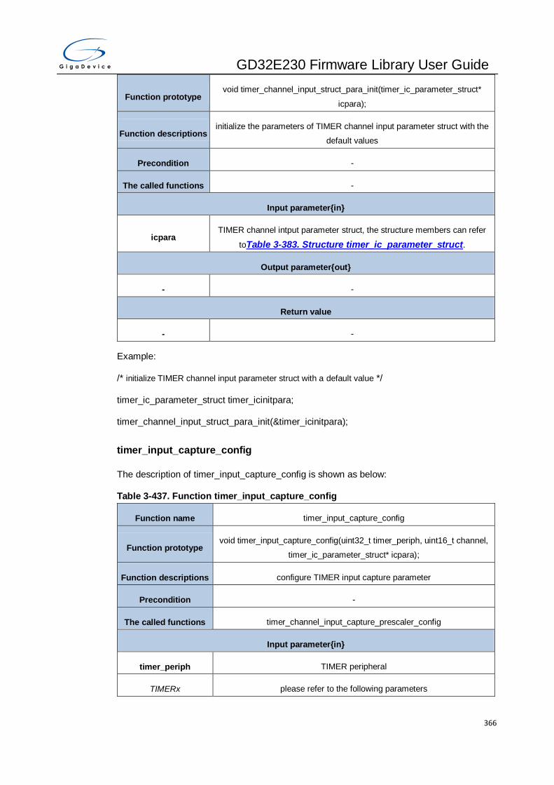
GD32E230 Firmware Library User Guide
366
Function prototype void timer_channel_input_struct_para_init(timer_ic_parameter_struct*
icpara);
Function descriptions initialize the parameters of TIMER channel input parameter struct with the
default values
Precondition -
The called functions -
Input parameter{in}
icpara TIMER channel intput parameter struct, the structure members can refer
toTable 3-383. Structure timer_ic_parameter_struct.
Output parameter{out}
- -
Return value
- -
Example:
/* initialize TIMER channel input parameter struct with a default value */
timer_ic_parameter_struct timer_icinitpara;
timer_channel_input_struct_para_init(&timer_icinitpara);
timer_input_capture_config
The description of timer_input_capture_config is shown as below:
Table 3-437. Function timer_input_capture_config
Function name timer_input_capture_config
Function prototype void timer_input_capture_config(uint32_t timer_periph, uint16_t channel,
timer_ic_parameter_struct* icpara);
Function descriptions configure TIMER input capture parameter
Precondition -
The called functions timer_channel_input_capture_prescaler_config
Input parameter{in}
timer_periph TIMER peripheral
TIMERx please refer to the following parameters

GD32E230 Firmware Library User Guide
367
Input parameter{in}
channel channel to be configured
TIMER_CH_0 TIMER channel 0(TIMERx (x=0, 2, 13..16))
TIMER_CH_1 TIMER channel 1(TIMERx (x=0, 2, 14))
TIMER_CH_2 TIMER channel 2(TIMERx (x=0, 2))
TIMER_CH_3 TIMER channel 3(TIMERx (x=0, 2))
Input parameter{in}
icpara TIMER channel intput parameter struct, the structure members can refer
toTable 3-383. Structure timer_ic_parameter_struct.
Output parameter{out}
- -
Return value
- -
Example:
/* configure TIMER0 input capture parameter */
timer_ic_parameter_struct timer_icinitpara;
timer_icinitpara.icpolarity = TIMER_IC_POLARITY_RISING;
timer_icinitpara.icselection = TIMER_IC_SELECTION_DIRECTTI;
timer_icinitpara.icprescaler = TIMER_IC_PSC_DIV1;
timer_icinitpara.icfilter = 0x0;
timer_input_capture_config(TIMER0, TIMER_CH_0, &timer_icinitpara);
timer_channel_input_capture_prescaler_config
The description of timer_channel_input_capture_prescaler_config is shown as below:
Table 3-438. Function timer_channel_input_capture_prescaler_config
Function name timer_channel_input_capture_prescaler_config
Function prototype void timer_channel_input_capture_prescaler_config(uint32_t timer_periph,
uint16_t channel, uint16_t prescaler);
Function descriptions configure TIMER channel input capture prescaler value
Precondition -
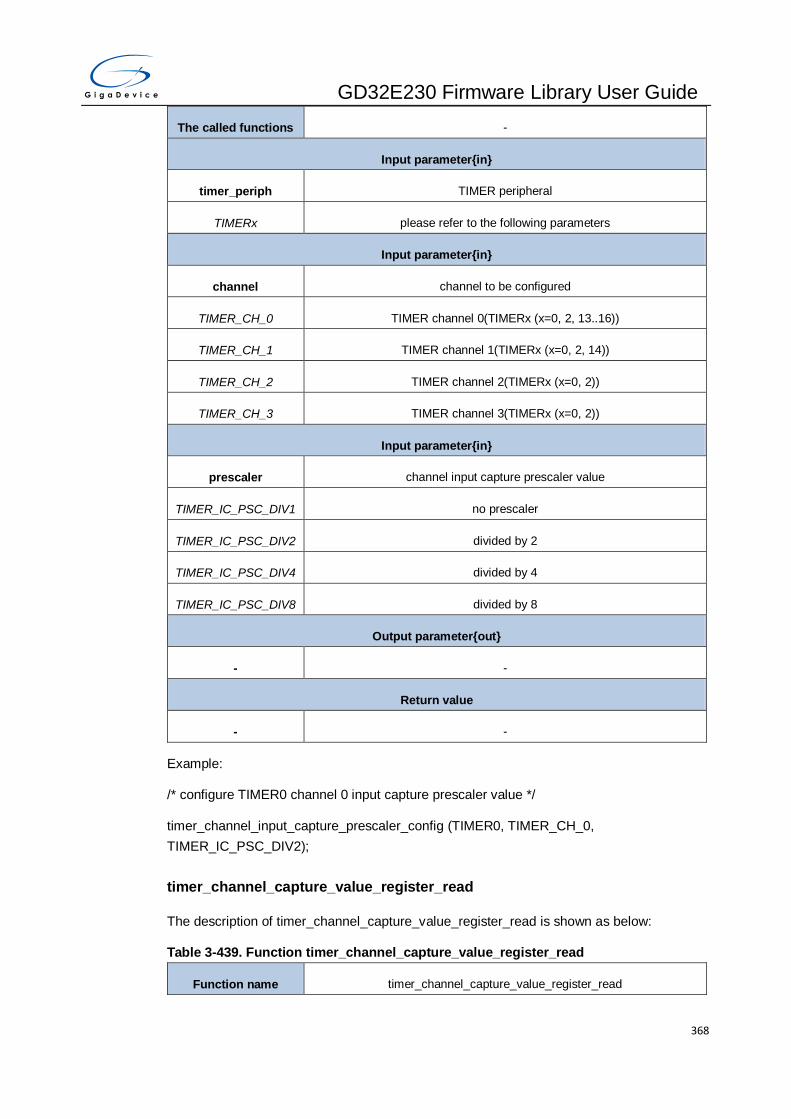
GD32E230 Firmware Library User Guide
368
The called functions -
Input parameter{in}
timer_periph TIMER peripheral
TIMERx please refer to the following parameters
Input parameter{in}
channel channel to be configured
TIMER_CH_0 TIMER channel 0(TIMERx (x=0, 2, 13..16))
TIMER_CH_1 TIMER channel 1(TIMERx (x=0, 2, 14))
TIMER_CH_2 TIMER channel 2(TIMERx (x=0, 2))
TIMER_CH_3 TIMER channel 3(TIMERx (x=0, 2))
Input parameter{in}
prescaler channel input capture prescaler value
TIMER_IC_PSC_DIV1 no prescaler
TIMER_IC_PSC_DIV2 divided by 2
TIMER_IC_PSC_DIV4 divided by 4
TIMER_IC_PSC_DIV8 divided by 8
Output parameter{out}
- -
Return value
- -
Example:
/* configure TIMER0 channel 0 input capture prescaler value */
timer_channel_input_capture_prescaler_config (TIMER0, TIMER_CH_0,
TIMER_IC_PSC_DIV2);
timer_channel_capture_value_register_read
The description of timer_channel_capture_value_register_read is shown as below:
Table 3-439. Function timer_channel_capture_value_register_read
Function name timer_channel_capture_value_register_read

GD32E230 Firmware Library User Guide
369
Function prototype uint32_t timer_channel_capture_value_register_read(uint32_t
timer_periph, uint16_t channel);
Function descriptions read TIMER channel capture compare register value
Precondition -
The called functions -
Input parameter{in}
timer_periph TIMER peripheral
TIMERx please refer to the following parameters
Input parameter{in}
channel channel to be configured
TIMER_CH_0 TIMER channel 0(TIMERx (x=0, 2, 13..16))
TIMER_CH_1 TIMER channel 1(TIMERx (x=0, 2, 14))
TIMER_CH_2 TIMER channel 2(TIMERx (x=0, 2))
TIMER_CH_3 TIMER channel 3(TIMERx (x=0, 2))
Output parameter{out}
- -
Return value
uint32_t channel capture compare register value (0~65535)
Example:
/* read TIMER0 channel 0 capture compare register value */
uint32_t ch0_value = 0;
ch0_value = timer_channel_capture_value_register_read (TIMER0, TIMER_CH_0);
timer_input_pwm_capture_config
The description of timer_input_pwm_capture_config is shown as below:
Table 3-440. Function timer_input_pwm_capture_config
Function name timer_input_pwm_capture_config
Function prototype void timer_input_pwm_capture_config(uint32_t timer_periph, uint16_t
channel, timer_ic_parameter_struct* icpwm);
Function descriptions configure TIMER input pwm capture function
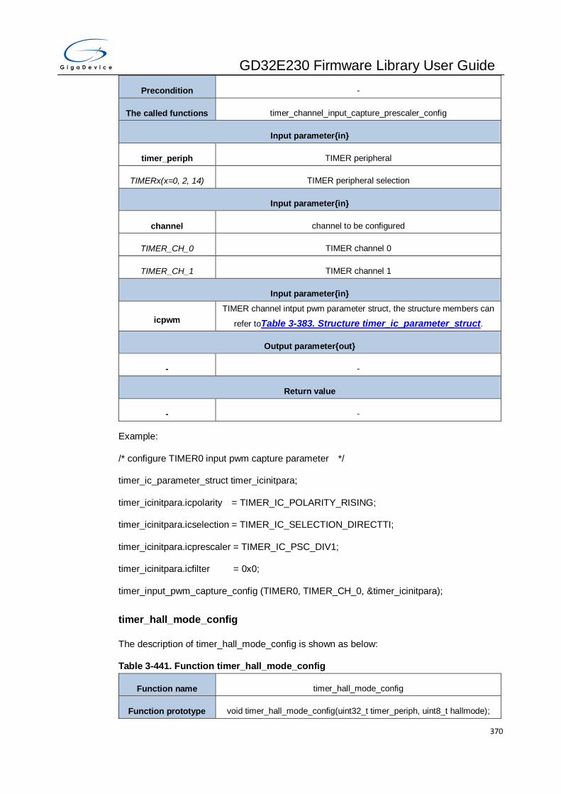
GD32E230 Firmware Library User Guide
370
Precondition -
The called functions timer_channel_input_capture_prescaler_config
Input parameter{in}
timer_periph TIMER peripheral
TIMERx(x=0, 2, 14) TIMER peripheral selection
Input parameter{in}
channel channel to be configured
TIMER_CH_0 TIMER channel 0
TIMER_CH_1 TIMER channel 1
Input parameter{in}
icpwm
TIMER channel intput pwm parameter struct, the structure members can
refer toTable 3-383. Structure timer_ic_parameter_struct.
Output parameter{out}
- -
Return value
- -
Example:
/* configure TIMER0 input pwm capture parameter */
timer_ic_parameter_struct timer_icinitpara;
timer_icinitpara.icpolarity = TIMER_IC_POLARITY_RISING;
timer_icinitpara.icselection = TIMER_IC_SELECTION_DIRECTTI;
timer_icinitpara.icprescaler = TIMER_IC_PSC_DIV1;
timer_icinitpara.icfilter = 0x0;
timer_input_pwm_capture_config (TIMER0, TIMER_CH_0, &timer_icinitpara);
timer_hall_mode_config
The description of timer_hall_mode_config is shown as below:
Table 3-441. Function timer_hall_mode_config
Function name timer_hall_mode_config
Function prototype void timer_hall_mode_config(uint32_t timer_periph, uint8_t hallmode);

GD32E230 Firmware Library User Guide
371
Function descriptions configure TIMER hall sensor mode
Precondition -
The called functions -
Input parameter{in}
timer_periph TIMER peripheral
TIMERx(x=0, 2) TIMER peripheral selection
Input parameter{in}
hallmode TIMER hall sensor mode state
TIMER_HALLINTERFA
CE_ENABLE TIMER hall sensor mode enable
TIMER_HALLINTERFA
CE_DISABLE TIMER hall sensor mode disable
Output parameter{out}
- -
Return value
- -
Example:
/* configure TIMER0 hall sensor mode */
timer_hall_mode_config (TIMER0, TIMER_HALLINTERFACE_ENABLE);
timer_input_trigger_source_select
The description of timer_input_trigger_source_select is shown as below:
Table 3-442. Function timer_input_trigger_source_select
Function name timer_input_trigger_source_select
Function prototype void timer_input_trigger_source_select(uint32_t timer_periph, uint32_t
intrigger);
Function descriptions select TIMER input trigger source
Precondition SMC[2:0] = 000
The called functions -
Input parameter{in}

GD32E230 Firmware Library User Guide
372
timer_periph TIMER peripheral
TIMERx(x=0, 2, 14) please refer to the following parameters
Input parameter{in}
intrigger trigger selection
TIMER_SMCFG_TRGS
EL_ITI0 Internal trigger input 0(ITI0,TIMERx(x=0, 2, 14))
TIMER_SMCFG_TRGS
EL_ITI1 Internal trigger input 0 (ITI1,TIMERx(x=0, 2, 14))
TIMER_SMCFG_TRGS
EL_ITI2 Internal trigger input 0 (ITI2, TIMERx(ITI2,TIMERx(x=0, 2))
TIMER_SMCFG_TRGS
EL_ITI3 Internal trigger input 0(ITI3,TIMERx(x=0, 2, 14))
TIMER_SMCFG_TRGS
EL_CI0F_ED CI0 edge flag (CI0F_ED,TIMERx(x=0, 2, 14))
TIMER_SMCFG_TRGS
EL_CI0FE0 channel 0 input Filtered output(CI0FE0,TIMERx(x=0, 2, 14))
TIMER_SMCFG_TRGS
EL_CI1FE1 channel 1 input Filtered output(CI1FE1,TIMERx(x=0, 2, 14))
TIMER_SMCFG_TRGS
EL_ETIFP External trigger input filter output(ETIFP,TIMERx(x=0, 2))
Output parameter{out}
- -
Return value
- -
Example:
/* select TIMER0 input trigger source */
timer_input_trigger_source_select (TIMER0, TIMER_SMCFG_TRGSEL_ITI0);
timer_master_output_trigger_source_select
The description of timer_master_output_trigger_source_select is shown as below:
Table 3-443. Function timer_master_output_trigger_source_select
Function name timer_master_output_trigger_source_select

GD32E230 Firmware Library User Guide
373
Function prototype void timer_master_output_trigger_source_select(uint32_t timer_periph,
uint32_t outrigger);
Function descriptions select TIMER master mode output trigger source
Precondition -
The called functions -
Input parameter{in}
timer_periph TIMER peripheral
TIMERx(x=0, 2, 5, 14) TIMER peripheral selection
Input parameter{in}
outrigger master mode control
TIMER_TRI_OUT_SRC
_RESET
Reset. When the UPG bit in the TIMERx_SWEVG register is set or a reset
is generated by the slave mode controller, a TRGO pulse occurs. And in
the latter case, the signal on TRGO is delayed compared to the actual
reset
TIMER_TRI_OUT_SRC
_ENABLE
Enable. This mode is useful to start several timers at the same time or to
control a window in which a slave timer is enabled. In this mode the master
mode controller selects the counter enable signal as TRGO. The counter
enable signal is set when CEN control bit is set or the trigger input in pause
mode is high. There is a delay between the trigger input in pause mode
and the TRGO output, except if the master-slave mode is selected.
TIMER_TRI_OUT_SRC
_UPDATE
Update. In this mode the master mode controller selects the update event
as TRGO.
TIMER_TRI_OUT_SRC
_CH0
Capture/compare pulse. In this mode the master mode controller generates
a TRGO pulse when a capture or a compare match occurred in channel 0.
TIMER_TRI_OUT_SRC
_O0CPRE
Compare. In this mode the master mode controller selects the O0CPRE
signal is used as TRGO.
TIMER_TRI_OUT_SRC
_O1CPRE
Compare. In this mode the master mode controller selects the O1CPRE
signal is used as TRGO.
TIMER_TRI_OUT_SRC
_O2CPRE
Compare. In this mode the master mode controller selects the O2CPRE
signal is used as TRGO.
TIMER_TRI_OUT_SRC
_O3CPRE
Compare. In this mode the master mode controller selects the O3CPRE
signal is used as TRGO.
Output parameter{out}
- -

GD32E230 Firmware Library User Guide
374
Return value
- -
Example:
/* select TIMER0 master mode output trigger source */
timer_master_output_trigger_source_select (TIMER0, TIMER_TRI_OUT_SRC_RESET);
timer_slave_mode_select
The description of timer_slave_mode_select is shown as below:
Table 3-444. Function timer_slave_mode_select
Function name timer_slave_mode_select
Function prototype void timer_slave_mode_select(uint32_t timer_periph, uint32_t slavemode);
Function descriptions select TIMER slave mode
Precondition -
The called functions -
Input parameter{in}
timer_periph TIMER peripheral
TIMERx(x=0, 2, 14) TIMER peripheral selection
Input parameter{in}
slavemode slave mode
TIMER_SLAVE_MODE_
DISABLE slave mode disable, TIMERx(x=0, 2, 14)
TIMER_ENCODER_MO
DE0 encoder mode 0, TIMERx(x=0, 2)
TIMER_ENCODER_MO
DE1 encoder mode 1, TIMERx(x=0, 2)
TIMER_ENCODER_MO
DE2 encoder mode 2, TIMERx(x=0, 2)
TIMER_SLAVE_MODE_
RESTART restart mode, TIMERx(x=0, 2, 14)
TIMER_SLAVE_MODE_
PAUSE pause mode, TIMERx(x=0, 2, 14)

GD32E230 Firmware Library User Guide
375
TIMER_SLAVE_MODE_
EVENT event mode, TIMERx(x=0, 2, 14)
TIMER_SLAVE_MODE_
EXTERNAL0 external clock mode 0, TIMERx(x=0, 2, 14)
Output parameter{out}
- -
Return value
- -
Example:
/* select TIMER0 slave mode */
timer_slave_mode_select (TIMER0, TIMER_ENCODER_MODE0);
timer_master_slave_mode_config
The description of timer_master_slave_mode_config is shown as below:
Table 3-445. Function timer_master_slave_mode_config
Function name timer_master_slave_mode_config
Function prototype void timer_master_slave_mode_config(uint32_t timer_periph, uint8_t
masterslave);
Function descriptions configure TIMER master slave mode
Precondition -
The called functions -
Input parameter{in}
timer_periph TIMER peripheral
TIMERx(x=0, 2, 14) TIMER peripheral selection
Input parameter{in}
masterslave master slave mode state
TIMER_MASTER_SLAV
E_MODE_ENABLE master slave mode enable
TIMER_MASTER_SLAV
E_MODE_DISABLE master slave mode disable
Output parameter{out}

GD32E230 Firmware Library User Guide
376
- -
Return value
- -
Example:
/* configure TIMER0 master slave mode */
timer_master_slave_mode_config (TIMER0, TIMER_MASTER_SLAVE_MODE_ENABLE);
timer_external_trigger_config
The description of timer_external_trigger_config is shown as below:
Table 3-446. Function timer_external_trigger_config
Function name timer_external_trigger_config
Function prototype void timer_external_trigger_config(uint32_t timer_periph, uint32_t
extprescaler, uint32_t expolarity, uint32_t extfilter);
Function descriptions configure TIMER external trigger input
Precondition -
The called functions -
Input parameter{in}
timer_periph TIMER peripheral
TIMERx(x=0, 2) TIMER peripheral selection
Input parameter{in}
extprescaler external trigger prescaler
TIMER_EXT_TRI_PSC_
OFF no divided
TIMER_EXT_TRI_PSC_
DIV2 divided by 2
TIMER_EXT_TRI_PSC_
DIV4 divided by 4
TIMER_EXT_TRI_PSC_
DIV8 divided by 8
Input parameter{in}
expolarity external trigger polarity

GD32E230 Firmware Library User Guide
377
TIMER_ETP_FALLING active low or falling edge active
TIMER_ETP_RISING active high or rising edge active
Input parameter{in}
extfilter external trigger filter control(0~15)
Output parameter{out}
- -
Return value
- -
Example:
/* configure TIMER0 external trigger input */
timer_external_trigger_config (TIMER0, TIMER_EXT_TRI_PSC_DIV2,
TIMER_ETP_FALLING, 10);
timer_quadrature_decoder_mode_config
The description of timer_quadrature_decoder_mode_config is shown as below:
Table 3-447. Function timer_quadrature_decoder_mode_config
Function name timer_quadrature_decoder_mode_config
Function prototype void timer_quadrature_decoder_mode_config(uint32_t timer_periph,
uint32_t decomode, uint16_t ic0polarity, uint16_t ic1polarity);
Function descriptions configure TIMER quadrature decoder mode
Precondition -
The called functions -
Input parameter{in}
timer_periph TIMER peripheral
TIMERx(x=0, 2) TIMER peripheral selection
Input parameter{in}
decomode quadrature decoder mode
TIMER_ENCODER_MO
DE0 counter counts on CI0FE0 edge depending on CI1FE1 level
TIMER_ENCODER_MO counter counts on CI1FE1 edge depending on CI0FE0 level

GD32E230 Firmware Library User Guide
378
DE1
TIMER_ENCODER_MO
DE2
counter counts on both CI0FE0 and CI1FE1 edges depending on the level
of the other input
Input parameter{in}
ic0polarity IC0 polarity
TIMER_IC_POLARITY_
RISING capture rising edge
TIMER_IC_POLARITY_
FALLING capture falling edge
Input parameter{in}
ic1polarity IC1 polarity
TIMER_IC_POLARITY_
RISING capture rising edge
TIMER_IC_POLARITY_
FALLING capture falling edge
Output parameter{out}
- -
Return value
- -
Example:
/* configure TIMER0 quadrature decoder mode */
timer_quadrature_decoder_mode_config (TIMER0, TIMER_ENCODER_MODE0,
TIMER_IC_POLARITY_RISING, TIMER_IC_POLARITY_RISING);
timer_internal_clock_config
The description of timer_internal_clock_config is shown as below:
Table 3-448. Function timer_internal_clock_config
Function name timer_internal_clock_config
Function prototype void timer_internal_clock_config(uint32_t timer_periph);
Function descriptions configure TIMER internal clock mode
Precondition -

GD32E230 Firmware Library User Guide
379
The called functions -
Input parameter{in}
timer_periph TIMER peripheral
TIMERx(x=0, 2, 14) TIMER peripheral selection
Output parameter{out}
- -
Return value
- -
Example:
/* configure TIMER0 internal clock mode */
timer_internal_clock_config (TIMER0);
timer_internal_trigger_as_external_clock_config
The description of timer_internal_trigger_as_external_clock_config is shown as below:
Table 3-449. Function timer_internal_trigger_as_external_clock_config
Function name timer_internal_trigger_as_external_clock_config
Function prototype void timer_internal_trigger_as_external_clock_config(uint32_t
timer_periph, uint32_t intrigger);
Function descriptions configure TIMER the internal trigger as external clock input
Precondition -
The called functions timer_input_trigger_source_select
Input parameter{in}
timer_periph TIMER peripheral
TIMERx(x=0, 2, 14) TIMER peripheral selection
Input parameter{in}
intrigger trigger selection
TIMER_SMCFG_TRGS
EL_ITI0 Internal trigger input 0 (ITI0), TIMERx(x=0, 2, 14)
TIMER_SMCFG_TRGS
EL_ITI1 Internal trigger input 0 (ITI1) , TIMERx(x=0, 2, 14)
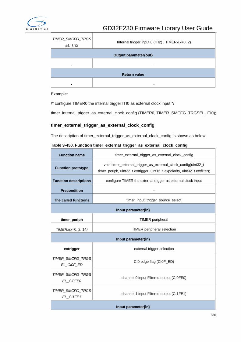
GD32E230 Firmware Library User Guide
380
TIMER_SMCFG_TRGS
EL_ITI2 Internal trigger input 0 (ITI2) , TIMERx(x=0, 2)
Output parameter{out}
- -
Return value
- -
Example:
/* configure TIMER0 the internal trigger ITI0 as external clock input */
timer_internal_trigger_as_external_clock_config (TIMER0, TIMER_SMCFG_TRGSEL_ITI0);
timer_external_trigger_as_external_clock_config
The description of timer_external_trigger_as_external_clock_config is shown as below:
Table 3-450. Function timer_external_trigger_as_external_clock_config
Function name timer_external_trigger_as_external_clock_config
Function prototype void timer_external_trigger_as_external_clock_config(uint32_t
timer_periph, uint32_t extrigger, uint16_t expolarity, uint32_t extfilter);
Function descriptions configure TIMER the external trigger as external clock input
Precondition -
The called functions timer_input_trigger_source_select
Input parameter{in}
timer_periph TIMER peripheral
TIMERx(x=0, 2, 14) TIMER peripheral selection
Input parameter{in}
extrigger external trigger selection
TIMER_SMCFG_TRGS
EL_CI0F_ED CI0 edge flag (CI0F_ED)
TIMER_SMCFG_TRGS
EL_CI0FE0 channel 0 input Filtered output (CI0FE0)
TIMER_SMCFG_TRGS
EL_CI1FE1 channel 1 input Filtered output (CI1FE1)
Input parameter{in}

GD32E230 Firmware Library User Guide
381
expolarity external trigger polarity
TIMER_IC_POLARITY_
RISING active high or rising edge active
TIMER_IC_POLARITY_
FALLING active low or falling edge active
TIMER_IC_POLARITY_
BOTH_EDGE falling edge or rising edge active
Input parameter{in}
extfilter external trigger filter control(0~15)
Output parameter{out}
- -
Return value
- -
Example:
/* configure TIMER0 the external trigger CI0FE0 as external clock input */
timer_external_trigger_as_external_clock_config (TIMER0,
TIMER_SMCFG_TRGSEL_CI0FE0, TIMER_IC_POLARITY_RISING, 0);
timer_external_clock_mode0_config
The description of timer_external_clock_mode0_config is shown as below:
Table 3-451. Function timer_external_clock_mode0_config
Function name timer_external_clock_mode0_config
Function prototype void timer_external_clock_mode0_config(uint32_t timer_periph, uint32_t
extprescaler, uint32_t expolarity, uint32_t extfilter);
Function descriptions configure TIMER the external clock mode0
Precondition -
The called functions timer_external_trigger_config
Input parameter{in}
timer_periph TIMER peripheral
TIMERx(x=0, 2) TIMER peripheral selection
Input parameter{in}

GD32E230 Firmware Library User Guide
382
extprescaler ETI external trigger prescaler
TIMER_EXT_TRI_PSC_
OFF no divided
TIMER_EXT_TRI_PSC_
DIV2 divided by 2
TIMER_EXT_TRI_PSC_
DIV4 divided by 4
TIMER_EXT_TRI_PSC_
DIV8 divided by 8
Input parameter{in}
expolarity ETI external trigger polarity
TIMER_ETP_FALLING active low or falling edge active
TIMER_ETP_RISING active high or rising edge active
Input parameter{in}
extfilter ETI external trigger filter control(0~15)
Output parameter{out}
- -
Return value
- -
Example:
/* configure TIMER0 the external clock mode0 */
timer_external_clock_mode0_config (TIMER0, TIMER_EXT_TRI_PSC_DIV2,
TIMER_ETP_FALLING, 0);
timer_external_clock_mode1_config
The description of timer_external_clock_mode1_config is shown as below:
Table 3-452. Function timer_external_clock_mode1_config
Function name timer_external_clock_mode1_config
Function prototype void timer_external_clock_mode1_config(uint32_t timer_periph, uint32_t
extprescaler, uint32_t expolarity, uint32_t extfilter);
Function descriptions configure TIMER the external clock mode1
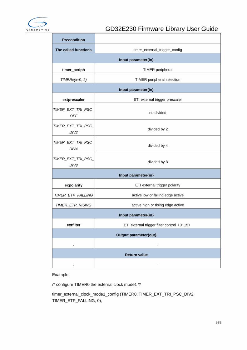
GD32E230 Firmware Library User Guide
383
Precondition -
The called functions timer_external_trigger_config
Input parameter{in}
timer_periph TIMER peripheral
TIMERx(x=0, 2) TIMER peripheral selection
Input parameter{in}
extprescaler ETI external trigger prescaler
TIMER_EXT_TRI_PSC_
OFF no divided
TIMER_EXT_TRI_PSC_
DIV2 divided by 2
TIMER_EXT_TRI_PSC_
DIV4 divided by 4
TIMER_EXT_TRI_PSC_
DIV8 divided by 8
Input parameter{in}
expolarity ETI external trigger polarity
TIMER_ETP_FALLING active low or falling edge active
TIMER_ETP_RISING active high or rising edge active
Input parameter{in}
extfilter ETI external trigger filter control(0~15)
Output parameter{out}
- -
Return value
- -
Example:
/* configure TIMER0 the external clock mode1 */
timer_external_clock_mode1_config (TIMER0, TIMER_EXT_TRI_PSC_DIV2,
TIMER_ETP_FALLING, 0);
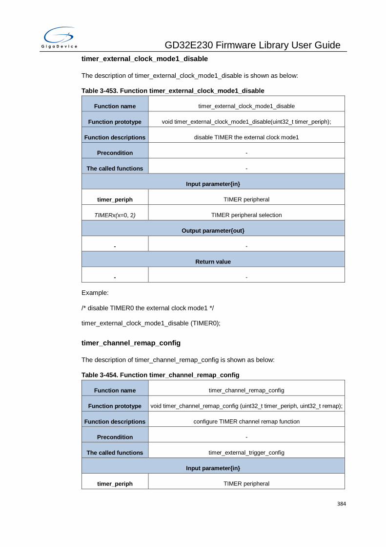
GD32E230 Firmware Library User Guide
384
timer_external_clock_mode1_disable
The description of timer_external_clock_mode1_disable is shown as below:
Table 3-453. Function timer_external_clock_mode1_disable
Function name timer_external_clock_mode1_disable
Function prototype void timer_external_clock_mode1_disable(uint32_t timer_periph);
Function descriptions disable TIMER the external clock mode1
Precondition -
The called functions -
Input parameter{in}
timer_periph TIMER peripheral
TIMERx(x=0, 2) TIMER peripheral selection
Output parameter{out}
- -
Return value
- -
Example:
/* disable TIMER0 the external clock mode1 */
timer_external_clock_mode1_disable (TIMER0);
timer_channel_remap_config
The description of timer_channel_remap_config is shown as below:
Table 3-454. Function timer_channel_remap_config
Function name timer_channel_remap_config
Function prototype void timer_channel_remap_config (uint32_t timer_periph, uint32_t remap);
Function descriptions configure TIMER channel remap function
Precondition -
The called functions timer_external_trigger_config
Input parameter{in}
timer_periph TIMER peripheral
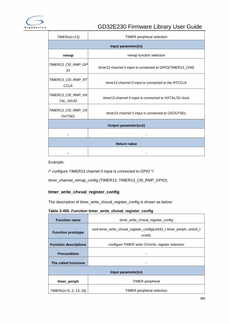
GD32E230 Firmware Library User Guide
385
TIMERx(x=13) TIMER peripheral selection
Input parameter{in}
remap remap function selection
TIMER13_CI0_RMP_GP
IO timer13 channel 0 input is connected to GPIO(TIMER13_CH0)
TIMER13_CI0_RMP_RT
CCLK timer13 channel 0 input is connected to the RTCCLK
TIMER13_CI0_RMP_HX
TAL_DIV32 timer13 channel 0 input is connected to HXTAL/32 clock
TIMER13_CI0_RMP_CK
OUTSEL timer13 channel 0 input is connected to CKOUTSEL
Output parameter{out}
- -
Return value
- -
Example:
/* configure TIMER13 channel 0 input is connected to GPIO */
timer_channel_remap_config (TIMER13, TIMER13_CI0_RMP_GPIO);
timer_write_chxval_register_config
The description of timer_write_chxval_register_config is shown as below:
Table 3-455. Function timer_write_chxval_register_config
Function name timer_write_chxval_register_config
Function prototype void timer_write_chxval_register_config(uint32_t timer_periph, uint16_t
ccsel);
Function descriptions configure TIMER write CHxVAL register selection
Precondition -
The called functions -
Input parameter{in}
timer_periph TIMER peripheral
TIMERx(x=0, 2, 13..16) TIMER peripheral selection

GD32E230 Firmware Library User Guide
386
Input parameter{in}
ccsel write CHxVAL register selection
TIMER_CHVSEL_DISA
BLE no effect
TIMER_CHVSEL_ENAB
LE
when write the CHxVAL register, if the write value is same as the CHxVAL
value, the write access is ignored
Output parameter{out}
- -
Return value
- -
Example:
/* configure TIMER0 write CHxVAL register selection */
timer_write_chxval_register_config(TIMER0, TIMER_CHVSEL_ENABLE);
timer_output_value_selection_config
The description of timer_output_value_selection_config is shown as below:
Table 3-456. Function timer_output_value_selection_config
Function name timer_output_value_selection_config
Function prototype void timer_output_value_selection_config(uint32_t timer_periph, uint16_t
outsel);
Function descriptions configure TIMER output value selection
Precondition -
The called functions -
Input parameter{in}
timer_periph TIMER peripheral
TIMERx(x=0, 14..16) TIMER peripheral selection
Input parameter{in}
outsel output value selection
TIMER_OUTSEL_DISA
BLE no effect
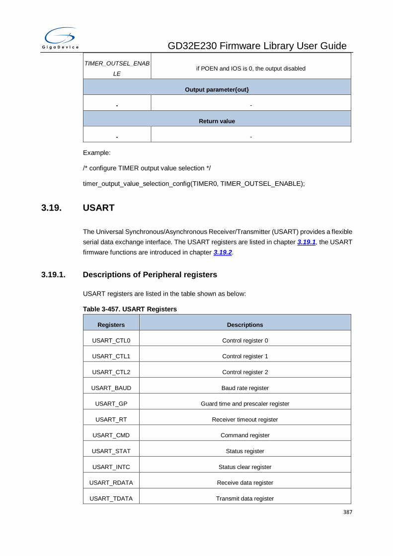
GD32E230 Firmware Library User Guide
387
TIMER_OUTSEL_ENAB
LE if POEN and IOS is 0, the output disabled
Output parameter{out}
- -
Return value
- -
Example:
/* configure TIMER output value selection */
timer_output_value_selection_config(TIMER0, TIMER_OUTSEL_ENABLE);
3.19. USART
The Universal Synchronous/Asynchronous Receiver/Transmitter (USART) provides a flexible
serial data exchange interface. The USART registers are listed in chapter 3.19.1, the USART
firmware functions are introduced in chapter 3.19.2.
3.19.1. Descriptions of Peripheral registers
USART registers are listed in the table shown as below:
Table 3-457. USART Registers
Registers Descriptions
USART_CTL0 Control register 0
USART_CTL1 Control register 1
USART_CTL2 Control register 2
USART_BAUD Baud rate register
USART_GP Guard time and prescaler register
USART_RT Receiver timeout register
USART_CMD Command register
USART_STAT Status register
USART_INTC Status clear register
USART_RDATA Receive data register
USART_TDATA Transmit data register

GD32E230 Firmware Library User Guide
388
Registers Descriptions
USART_CHC Coherence control register
USART_RFCS Receive FIFO control and status register
3.19.2. Descriptions of Peripheral functions
USART firmware functions are listed in the table shown as below:
Table 3-458. USART firmware function
Function name Function description
usart_deinit reset USART
usart_baudrate_set configure USART baud rate value
usart_parity_config configure USART parity function
usart_word_length_set configure USART word length
usart_stop_bit_set configure USART stop bit length
usart_enable enable USART
usart_disable disable USART
usart_transmit_config configure USART transmitter
usart_receive_config configure USART receiver
usart_data_first_config data is transmitted/received with the LSB/MSB first
usart_invert_config configure USART inverted
usart_overrun_enable enable the USART overrun function
usart_overrun_disable disable the USART overrun function
usart_oversample_config configure the USART oversample mode
usart_sample_bit_config configure sample bit method
usart_receiver_timeout_enable enable receiver timeout
usart_receiver_timeout_disable disable receiver timeout
usart_receiver_timeout_threshold_con
fig configure receiver timeout threshold
usart_data_transmit USART transmit data function
usart_data_receive USART receive data function
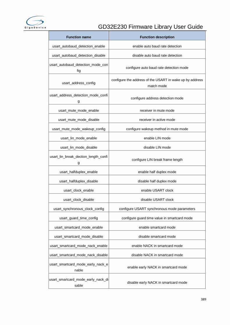
GD32E230 Firmware Library User Guide
389
Function name Function description
usart_autobaud_detection_enable enable auto baud rate detection
usart_autobaud_detection_disable disable auto baud rate detection
usart_autobaud_detection_mode_con
fig configure auto baud rate detection mode
usart_address_config configure the address of the USART in wake up by address
match mode
usart_address_detection_mode_confi
g configure address detection mode
usart_mute_mode_enable receiver in mute mode
usart_mute_mode_disable receiver in active mode
usart_mute_mode_wakeup_config configure wakeup method in mute mode
usart_lin_mode_enable enable LIN mode
usart_lin_mode_disable disable LIN mode
usart_lin_break_dection_length_confi
g configure LIN break frame length
usart_halfduplex_enable enable half duplex mode
usart_halfduplex_disable disable half duplex mode
usart_clock_enable enable USART clock
usart_clock_disable disable USART clock
usart_synchronous_clock_config configure USART synchronous mode parameters
usart_guard_time_config configure guard time value in smartcard mode
usart_smartcard_mode_enable enable smartcard mode
usart_smartcard_mode_disable disable smartcard mode
usart_smartcard_mode_nack_enable enable NACK in smartcard mode
usart_smartcard_mode_nack_disable disable NACK in smartcard mode
usart_smartcard_mode_early_nack_e
nable enable early NACK in smartcard mode
usart_smartcard_mode_early_nack_di
sable disable early NACK in smartcard mode
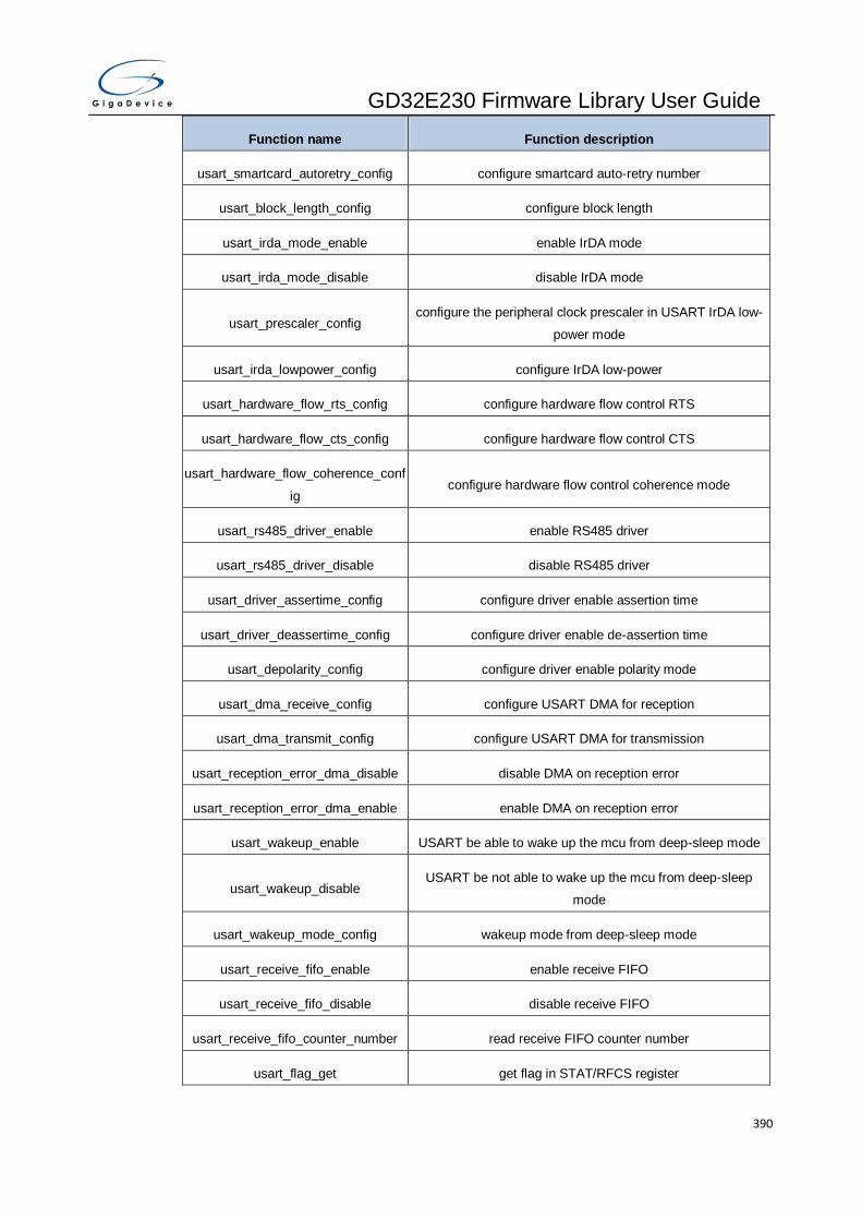
GD32E230 Firmware Library User Guide
390
Function name Function description
usart_smartcard_autoretry_config configure smartcard auto-retry number
usart_block_length_config configure block length
usart_irda_mode_enable enable IrDA mode
usart_irda_mode_disable disable IrDA mode
usart_prescaler_config configure the peripheral clock prescaler in USART IrDA low-
power mode
usart_irda_lowpower_config configure IrDA low-power
usart_hardware_flow_rts_config configure hardware flow control RTS
usart_hardware_flow_cts_config configure hardware flow control CTS
usart_hardware_flow_coherence_conf
ig configure hardware flow control coherence mode
usart_rs485_driver_enable enable RS485 driver
usart_rs485_driver_disable disable RS485 driver
usart_driver_assertime_config configure driver enable assertion time
usart_driver_deassertime_config configure driver enable de-assertion time
usart_depolarity_config configure driver enable polarity mode
usart_dma_receive_config configure USART DMA for reception
usart_dma_transmit_config configure USART DMA for transmission
usart_reception_error_dma_disable disable DMA on reception error
usart_reception_error_dma_enable enable DMA on reception error
usart_wakeup_enable USART be able to wake up the mcu from deep-sleep mode
usart_wakeup_disable USART be not able to wake up the mcu from deep-sleep
mode
usart_wakeup_mode_config wakeup mode from deep-sleep mode
usart_receive_fifo_enable enable receive FIFO
usart_receive_fifo_disable disable receive FIFO
usart_receive_fifo_counter_number read receive FIFO counter number
usart_flag_get get flag in STAT/RFCS register
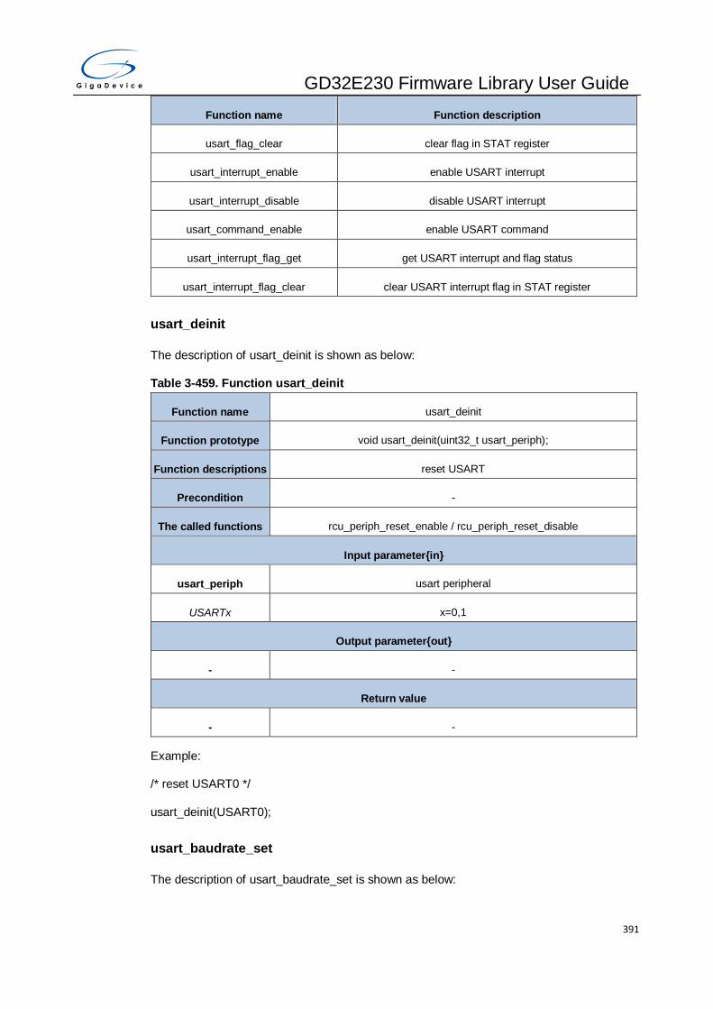
GD32E230 Firmware Library User Guide
391
Function name Function description
usart_flag_clear clear flag in STAT register
usart_interrupt_enable enable USART interrupt
usart_interrupt_disable disable USART interrupt
usart_command_enable enable USART command
usart_interrupt_flag_get get USART interrupt and flag status
usart_interrupt_flag_clear clear USART interrupt flag in STAT register
usart_deinit
The description of usart_deinit is shown as below:
Table 3-459. Function usart_deinit
Function name usart_deinit
Function prototype void usart_deinit(uint32_t usart_periph);
Function descriptions reset USART
Precondition -
The called functions rcu_periph_reset_enable / rcu_periph_reset_disable
Input parameter{in}
usart_periph usart peripheral
USARTx x=0,1
Output parameter{out}
- -
Return value
- -
Example:
/* reset USART0 */
usart_deinit(USART0);
usart_baudrate_set
The description of usart_baudrate_set is shown as below:
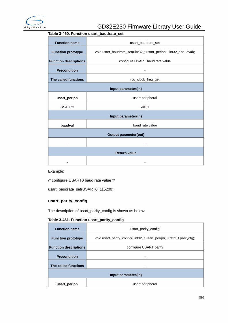
GD32E230 Firmware Library User Guide
392
Table 3-460. Function usart_baudrate_set
Function name usart_baudrate_set
Function prototype void usart_baudrate_set(uint32_t usart_periph, uint32_t baudval);
Function descriptions configure USART baud rate value
Precondition -
The called functions rcu_clock_freq_get
Input parameter{in}
usart_periph usart peripheral
USARTx x=0,1
Input parameter{in}
baudval baud rate value
Output parameter{out}
- -
Return value
- -
Example:
/* configure USART0 baud rate value */
usart_baudrate_set(USART0, 115200);
usart_parity_config
The description of usart_parity_config is shown as below:
Table 3-461. Function usart_parity_config
Function name usart_parity_config
Function prototype void usart_parity_config(uint32_t usart_periph, uint32_t paritycfg);
Function descriptions configure USART parity
Precondition -
The called functions -
Input parameter{in}
usart_periph usart peripheral

GD32E230 Firmware Library User Guide
393
USARTx x=0,1
Input parameter{in}
paritycfg configure USART parity
USART_PM_NONE no parity
USART_PM_ODD odd parity
USART_PM_EVEN even parity
Output parameter{out}
- -
Return value
- -
Example:
/* configure USART0 parity */
usart_parity_config(USART0, USART_PM_EVEN);
usart_word_length_set
The description of usart_word_length_set is shown as below:
Table 3-462. Function usart_word_length_set
Function name usart_word_length_set
Function prototype void usart_word_length_set(uint32_t usart_periph, uint32_t wlen);
Function descriptions configure USART word length
Precondition -
The called functions -
Input parameter{in}
usart_periph usart peripheral
USARTx x=0,1
Input parameter{in}
wlen USART word length configure
USART_WL_8BIT 8 bits
USART_WL_9BIT 9 bits
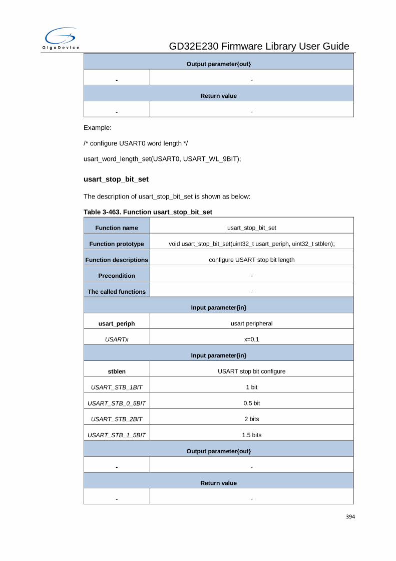
GD32E230 Firmware Library User Guide
394
Output parameter{out}
- -
Return value
- -
Example:
/* configure USART0 word length */
usart_word_length_set(USART0, USART_WL_9BIT);
usart_stop_bit_set
The description of usart_stop_bit_set is shown as below:
Table 3-463. Function usart_stop_bit_set
Function name usart_stop_bit_set
Function prototype void usart_stop_bit_set(uint32_t usart_periph, uint32_t stblen);
Function descriptions configure USART stop bit length
Precondition -
The called functions -
Input parameter{in}
usart_periph usart peripheral
USARTx x=0,1
Input parameter{in}
stblen USART stop bit configure
USART_STB_1BIT 1 bit
USART_STB_0_5BIT 0.5 bit
USART_STB_2BIT 2 bits
USART_STB_1_5BIT 1.5 bits
Output parameter{out}
- -
Return value
- -

GD32E230 Firmware Library User Guide
395
Example:
/* configure USART0 stop bit length */
usart_stop_bit_set(USART0, USART_STB_1_5BIT);
usart_enable
The description of usart_enable is shown as below:
Table 3-464. Function usart_enable
Function name usart_enable
Function prototype void usart_enable(uint32_t usart_periph);
Function descriptions enable USART
Precondition -
The called functions -
Input parameter{in}
usart_periph usart peripheral
USARTx x=0,1
Output parameter{out}
- -
Return value
- -
Example:
/* enable USART0 */
usart_enable(USART0);
usart_disable
The description of usart_disable is shown as below:
Table 3-465. Function usart_disable
Function name usart_disable
Function prototype void usart_disable(uint32_t usart_periph);
Function descriptions disable USART
Precondition -

GD32E230 Firmware Library User Guide
396
The called functions -
Input parameter{in}
usart_periph usart peripheral
USARTx x=0,1
Output parameter{out}
- -
Return value
- -
Example:
/* disable USART0 */
usart_disable(USART0);
usart_transmit_config
The description of usart_transmit_config is shown as below:
Table 3-466. Function usart_transmit_config
Function name usart_transmit_config
Function prototype void usart_transmit_config(uint32_t usart_periph, uint32_t txconfig);
Function descriptions configure USART transmitter
Precondition -
The called functions -
Input parameter{in}
usart_periph usart peripheral
USARTx x=0,1
Input parameter{in}
txconfig enable or disable USART transmitter
USART_TRANSMIT_E
NABLE enable USART transmission
USART_TRANSMIT_DI
SABLE disable USART transmission
Output parameter{out}

GD32E230 Firmware Library User Guide
397
- -
Return value
- -
Example:
/* configure USART0 transmitter */
usart_transmit_config(USART0,USART_TRANSMIT_ENABLE);
usart_receive_config
The description of usart_receive_config is shown as below:
Table 3-467. Function usart_receive_config
Function name usart_receive_config
Function prototype void usart_receive_config(uint32_t usart_periph, uint32_t rxconfig);
Function descriptions configure USART receiver
Precondition -
The called functions -
Input parameter{in}
usart_periph usart peripheral
USARTx x=0,1
Input parameter{in}
rxconfig enable or disable USART receiver
USART_RECEIVE_EN
ABLE enable USART reception
USART_RECEIVE_DIS
ABLE disable USART reception
Output parameter{out}
- -
Return value
- -
Example:
/* Configure USART0 receiver */
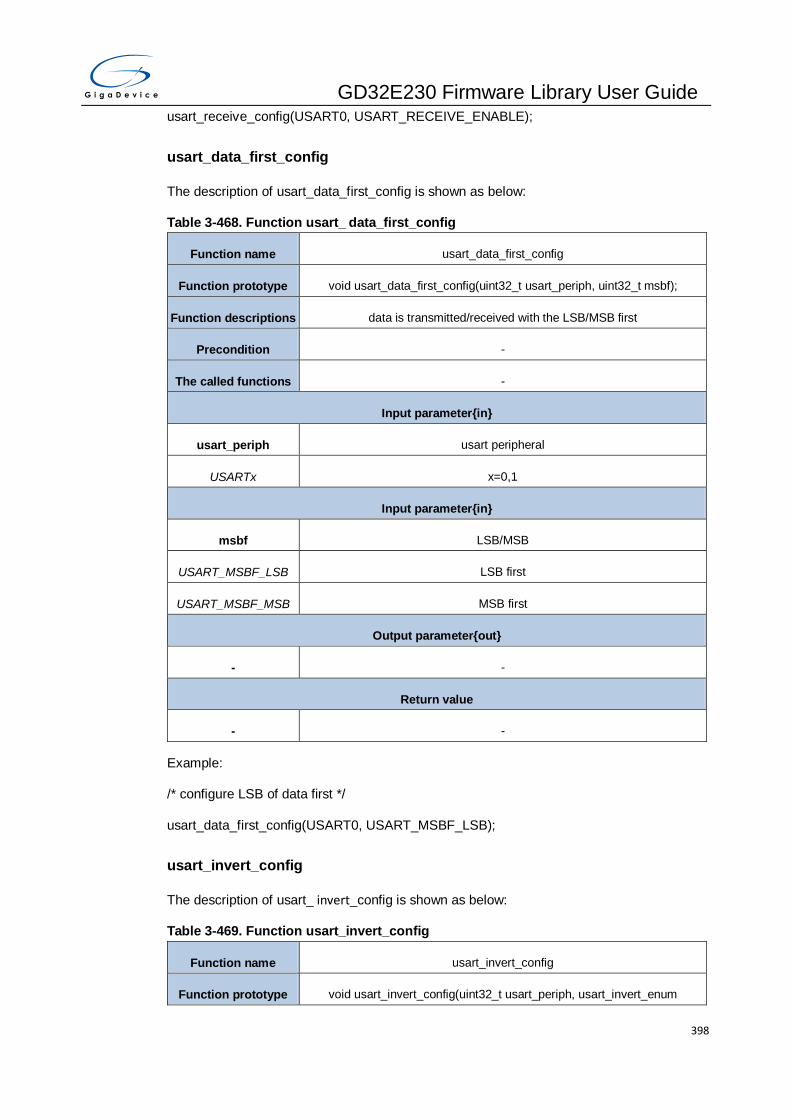
GD32E230 Firmware Library User Guide
398
usart_receive_config(USART0, USART_RECEIVE_ENABLE);
usart_data_first_config
The description of usart_data_first_config is shown as below:
Table 3-468. Function usart_ data_first_config
Function name usart_data_first_config
Function prototype void usart_data_first_config(uint32_t usart_periph, uint32_t msbf);
Function descriptions data is transmitted/received with the LSB/MSB first
Precondition -
The called functions -
Input parameter{in}
usart_periph usart peripheral
USARTx x=0,1
Input parameter{in}
msbf LSB/MSB
USART_MSBF_LSB LSB first
USART_MSBF_MSB MSB first
Output parameter{out}
- -
Return value
- -
Example:
/* configure LSB of data first */
usart_data_first_config(USART0, USART_MSBF_LSB);
usart_invert_config
The description of usart_ invert_config is shown as below:
Table 3-469. Function usart_invert_config
Function name usart_invert_config
Function prototype void usart_invert_config(uint32_t usart_periph, usart_invert_enum
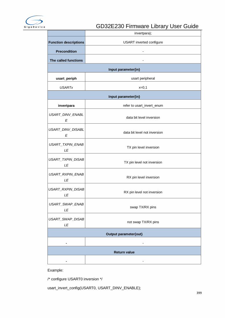
GD32E230 Firmware Library User Guide
399
invertpara);
Function descriptions USART inverted configure
Precondition -
The called functions -
Input parameter{in}
usart_periph usart peripheral
USARTx x=0,1
Input parameter{in}
invertpara refer to usart_invert_enum
USART_DINV_ENABL
E data bit level inversion
USART_DINV_DISABL
E data bit level not inversion
USART_TXPIN_ENAB
LE TX pin level inversion
USART_TXPIN_DISAB
LE TX pin level not inversion
USART_RXPIN_ENAB
LE RX pin level inversion
USART_RXPIN_DISAB
LE RX pin level not inversion
USART_SWAP_ENAB
LE swap TX/RX pins
USART_SWAP_DISAB
LE not swap TX/RX pins
Output parameter{out}
- -
Return value
- -
Example:
/* configure USART0 inversion */
usart_invert_config(USART0, USART_DINV_ENABLE);

GD32E230 Firmware Library User Guide
400
usart_overrun_enable
The description of usart_overrun_enable is shown as below:
Table 3-470. Function usart_overrun_enable
Function name usart_overrun_enable
Function prototype void usart_overrun_enable(uint32_t usart_periph);
Function descriptions enable the USART overrun function
Precondition -
The called functions -
Input parameter{in}
usart_periph usart peripheral
USARTx x=0,1
Output parameter{out}
- -
Return value
- -
Example:
/* enable USART0 overrun */
usart_overrun_enable(USART0);
usart_overrun_disable
The description of usart_overrun_disable is shown as below:
Table 3-471. Function usart_overrun_disable
Function name usart_overrun_disable
Function prototype void usart_overrun_disable(uint32_t usart_periph);
Function descriptions disable the USART overrun function
Precondition -
The called functions -
Input parameter{in}
usart_periph usart peripheral

GD32E230 Firmware Library User Guide
401
USARTx x=0,1
Output parameter{out}
- -
Return value
- -
Example:
/* disable USART0 overrun */
usart_overrun_disable(USART0);
usart_oversample_config
The description of usart_oversample_config is shown as below:
Table 3-472. Function usart_oversample_config
Function name usart_oversample_config
Function prototype void usart_oversample_config(uint32_t usart_periph, uint32_t oversamp);
Function descriptions configure the USART oversample mode
Precondition -
The called functions -
Input parameter{in}
usart_periph usart peripheral
USARTx x=0,1
Input parameter{in}
oversamp oversample value
USART_OVSMOD_8 oversampling by 8
USART_OVSMOD_16 oversampling by 16
Output parameter{out}
- -
Return value
- -
Example:

GD32E230 Firmware Library User Guide
402
/* config USART0 oversampling by 8 */
usart_oversample_config(USART0,USART_OVSMOD_8);
usart_sample_bit_config
The description of usart_sample_bit_config is shown as below:
Table 3-473. Function usart_sample_bit_config
Function name usart_sample_bit_config
Function prototype void usart_sample_bit_config(uint32_t usart_periph, uint32_t osb);
Function descriptions configure the sample bit method
Precondition -
The called functions -
Input parameter{in}
usart_periph usart peripheral
USARTx x=0,1
Input parameter{in}
osb sample bit
USART_OSB_1BIT 1 bit
USART_OSB_3BIT 3 bits
Output parameter{out}
- -
Return value
- -
Example:
/* config USART0 1 bit sample mode */
usart_sample_bit_config(USART0,USART_OSB_1BIT);
usart_receiver_timeout_enable
The description of usart_receiver_timeout_enable is shown as below:
Table 3-474. Function usart_receiver_timeout_enable
Function name usart_receiver_timeout_enable

GD32E230 Firmware Library User Guide
403
Function prototype void usart_receiver_timeout_enable(uint32_t usart_periph);
Function descriptions enable receiver timeout
Precondition -
The called functions -
Input parameter{in}
usart_periph usart peripheral
USARTx x=0
Output parameter{out}
- -
Return value
- -
Example:
/* enable USART0 receiver timeout */
usart_receiver_timeout_enable(USART0);
usart_receiver_timeout_disable
The description of usart_receiver_timeout_disable is shown as below:
Table 3-475. Function usart_receiver_timeout_disable
Function name usart_receiver_timeout_disable
Function prototype void usart_receiver_timeout_disable(uint32_t usart_periph);
Function descriptions disable receiver timeout
Precondition -
The called functions -
Input parameter{in}
usart_periph usart peripheral
USARTx x=0
Output parameter{out}
- -
Return value

GD32E230 Firmware Library User Guide
404
- -
Example:
/* disable USART0 receiver timeout */
usart_receiver_timeout_disable(USART0);
usart_receiver_timeout_threshold_config
The description of usart_receiver_timeout_threshold_config is shown as below:
Table 3-476. Function usart_receiver_timeout_threshold_config
Function name usart_receiver_timeout_threshold_config
Function prototype void usart_receiver_timeout_threshold_config(uint32_t usart_periph,
uint32_t rtimeout);
Function descriptions configure receiver timeout threshold
Precondition -
The called functions -
Input parameter{in}
usart_periph usart peripheral
USARTx x=0
Input parameter{in}
rtimeout receiver timeout
0x00000000-
0x00FFFFFF receiver timeout value
Output parameter{out}
- -
Return value
- -
Example:
/* set the receiver timeout threshold of USART0*/
usart_receiver_timeout_ threshold_config(USART0,115200*3);
usart_data_transmit
The description of usart_data_transmit is shown as below:
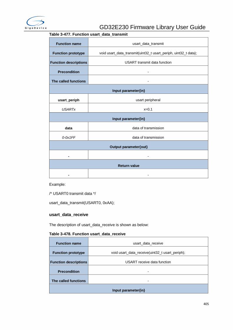
GD32E230 Firmware Library User Guide
405
Table 3-477. Function usart_data_transmit
Function name usart_data_transmit
Function prototype void usart_data_transmit(uint32_t usart_periph, uint32_t data);
Function descriptions USART transmit data function
Precondition -
The called functions -
Input parameter{in}
usart_periph usart peripheral
USARTx x=0,1
Input parameter{in}
data data of transmission
0-0x1FF data of transmission
Output parameter{out}
- -
Return value
- -
Example:
/* USART0 transmit data */
usart_data_transmit(USART0, 0xAA);
usart_data_receive
The description of usart_data_receive is shown as below:
Table 3-478. Function usart_data_receive
Function name usart_data_receive
Function prototype void usart_data_receive(uint32_t usart_periph);
Function descriptions USART receive data function
Precondition -
The called functions -
Input parameter{in}
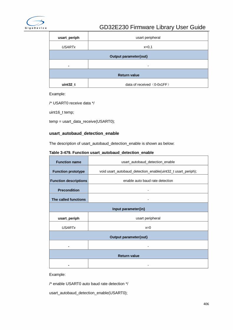
GD32E230 Firmware Library User Guide
406
usart_periph usart peripheral
USARTx x=0,1
Output parameter{out}
- -
Return value
uint32_t data of received(0-0x1FF)
Example:
/* USART0 receive data */
uint16_t temp;
temp = usart_data_receive(USART0);
usart_autobaud_detection_enable
The description of usart_autobaud_detection_enable is shown as below:
Table 3-479. Function usart_autobaud_detection_enable
Function name usart_autobaud_detection_enable
Function prototype void usart_autobaud_detection_enable(uint32_t usart_periph);
Function descriptions enable auto baud rate detection
Precondition -
The called functions -
Input parameter{in}
usart_periph usart peripheral
USARTx x=0
Output parameter{out}
- -
Return value
- -
Example:
/* enable USART0 auto baud rate detection */
usart_autobaud_detection_enable(USART0);

GD32E230 Firmware Library User Guide
407
usart_autobaud_detection_disable
The description of usart_autobaud_detection_disable is shown as below:
Table 3-480. Function usart_autobaud_detection_disable
Function name usart_autobaud_detection_disable
Function prototype void usart_autobaud_detection_disable(uint32_t usart_periph);
Function descriptions disable auto baud rate detection
Precondition -
The called functions -
Input parameter{in}
usart_periph usart peripheral
USARTx x=0
Output parameter{out}
- -
Return value
- -
Example:
/* disable USART0 auto baud rate detection */
usart_autobaud_detection_disable(USART0);
usart_autobaud_detection_mode_config
The description of usart_autobaud_detection_mode_config is shown as below:
Table 3-481. Function usart_autobaud_detection_mode_config
Function name usart_autobaud_detection_mode_config
Function prototype void usart_autobaud_detection_mode_config(uint32_t usart_periph,
uint32_t abdmod);
Function descriptions configure auto baud rate detection mode
Precondition -
The called functions -
Input parameter{in}
usart_periph usart peripheral

GD32E230 Firmware Library User Guide
408
USARTx x=0
Input parameter{in}
abdmod auto baud rate detection mode
USART_ABDM_FTOR falling edge to rising edge measurement
USART_ABDM_FTOF falling edge to falling edge measurement
Output parameter{out}
- -
Return value
- -
Example:
/* configure USART0 auto baud rate detection mode */
usart_autobaud_detection_mode_config(USART0, USART_ABDM_FTOR);
usart_address_config
The description of usart_address_config is shown as below:
Table 3-482. Function usart_address_config
Function name usart_address_config
Function prototype void usart_address_config(uint32_t usart_periph, uint8_t addr);
Function descriptions configure the address of the USART terminal
Precondition -
The called functions -
Input parameter{in}
usart_periph usart peripheral
USARTx x=0,1
Input parameter{in}
addr address of USART
0-0xFF address of USART
Output parameter{out}
- -

GD32E230 Firmware Library User Guide
409
Return value
- -
Example:
/* configure address of the USART0 */
usart_address_config(USART0, 0x00);
usart_address_detection_mode_config
The description of usart_address_detection_mode_config is shown as below:
Table 3-483. Function usart_address_detection_mode_config
Function name usart_address_detection_mode_config
Function prototype void usart_address_detection_mode_config(uint32_t usart_periph, uint32_t
addmod);
Function descriptions configure address detection mode
Precondition -
The called functions -
Input parameter{in}
usart_periph usart peripheral
USARTx x=0,1
Input parameter{in}
addmod address detection mode
USART_ADDM_4BIT 4 bits
USART_ADDM_FULLB
IT full bits
Output parameter{out}
- -
Return value
- -
Example:
/*configure address detection mode */
usart_address_config(USART0, USART_ADDM_4BIT);

GD32E230 Firmware Library User Guide
410
usart_mute_mode_enable
The description of usart_mute_mode_enable is shown as below:
Table 3-484. Function usart_mute_mode_enable
Function name usart_mute_mode_enable
Function prototype void usart_mute_mode_enable(uint32_t usart_periph);
Function descriptions enable mute mode
Precondition -
The called functions -
Input parameter{in}
usart_periph usart peripheral
USARTx x=0,1
Output parameter{out}
- -
Return value
- -
Example:
/* enable USART0 receiver in mute mode */
usart_mute_mode_enable(USART0);
usart_mute_mode_disable
The description of usart_mute_mode_disable is shown as below:
Table 3-485. Function usart_mute_mode_disable
Function name usart_mute_mode_disable
Function prototype void usart_mute_mode_disable(uint32_t usart_periph);
Function descriptions disable mute mode
Precondition -
The called functions -
Input parameter{in}
usart_periph usart peripheral
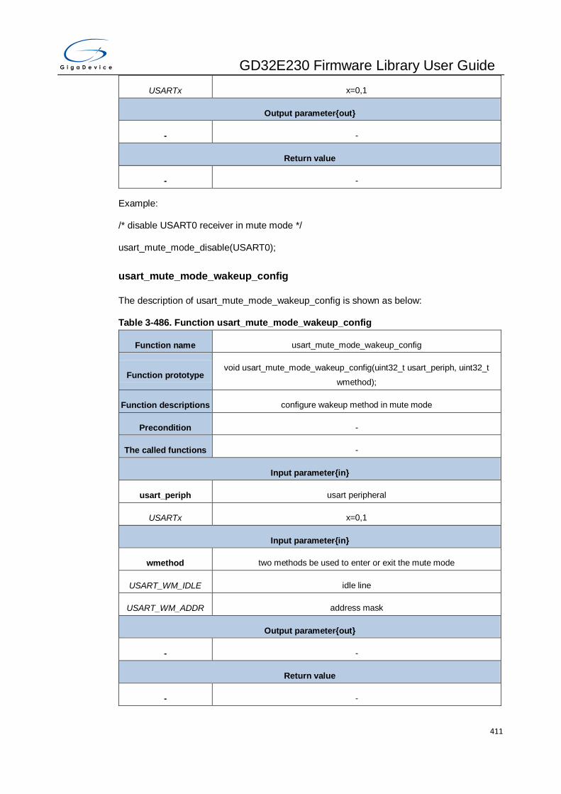
GD32E230 Firmware Library User Guide
411
USARTx x=0,1
Output parameter{out}
- -
Return value
- -
Example:
/* disable USART0 receiver in mute mode */
usart_mute_mode_disable(USART0);
usart_mute_mode_wakeup_config
The description of usart_mute_mode_wakeup_config is shown as below:
Table 3-486. Function usart_mute_mode_wakeup_config
Function name usart_mute_mode_wakeup_config
Function prototype void usart_mute_mode_wakeup_config(uint32_t usart_periph, uint32_t
wmethod);
Function descriptions configure wakeup method in mute mode
Precondition -
The called functions -
Input parameter{in}
usart_periph usart peripheral
USARTx x=0,1
Input parameter{in}
wmethod two methods be used to enter or exit the mute mode
USART_WM_IDLE idle line
USART_WM_ADDR address mask
Output parameter{out}
- -
Return value
- -

GD32E230 Firmware Library User Guide
412
Example:
/* configure USART0 wakeup method in mute mode */
usart_mute_mode_wakeup_config(USART0, USART_WM_IDLE);
usart_lin_mode_enable
The description of usart_lin_mode_enable is shown as below:
Table 3-487. Function usart_lin_mode_enable
Function name usart_lin_mode_enable
Function prototype void usart_lin_mode_enable(uint32_t usart_periph);
Function descriptions enable LIN mode
Precondition -
The called functions -
Input parameter{in}
usart_periph usart peripheral
USARTx x=0
Output parameter{out}
- -
Return value
- -
Example:
/* USART0 LIN mode enable */
usart_lin_mode_enable(USART0);
usart_lin_mode_disable
The description of usart_lin_mode_disable is shown as below:
Table 3-488. Function usart_lin_mode_disable
Function name usart_lin_mode_disable
Function prototype void usart_lin_mode_disable(uint32_t usart_periph);
Function descriptions disable LIN mode
Precondition -

GD32E230 Firmware Library User Guide
413
The called functions -
Input parameter{in}
usart_periph usart peripheral
USARTx x=0
Output parameter{out}
- -
Return value
- -
Example:
/* USART0 LIN mode disable */
usart_lin_mode_disable(USART0);
usart_lin_break_dection_length_config
The description of usart_lin_break_dection_length_config is shown as below:
Table 3-489. Function usart_lin_break_dection_length_config
Function name usart_lin_break_dection_length_config
Function prototype void usart_lin_break_dection_length_config(uint32_t usart_periph, uint32_t
lblen);
Function descriptions configure lin break frame length
Precondition -
The called functions -
Input parameter{in}
usart_periph usart peripheral
USARTx x=0
Input parameter{in}
lblen two methods be used to enter or exit the mute mode
USART_LBLEN_10B 10 bits
USART_LBLEN_11B 11 bits
Output parameter{out}

GD32E230 Firmware Library User Guide
414
- -
Return value
- -
Example:
/* configure LIN break frame length */
usart_lin_break_dection_length_config(USART0, USART_LBLEN_10B);
usart_halfduplex_enable
The description of usart_halfduplex_enable is shown as below:
Table 3-490. Function usart_halfduplex_enable
Function name usart_halfduplex_enable
Function prototype void usart_halfduplex_enable(uint32_t usart_periph);
Function descriptions enable half-duplex mode
Precondition -
The called functions -
Input parameter{in}
usart_periph usart peripheral
USARTx x=0,1
Output parameter{out}
- -
Return value
- -
Example:
/* enable USART0 half duplex mode*/
usart_halfduplex_enable(USART0);
usart_halfduplex_disable
The description of usart_halfduplex_disable is shown as below:
Table 3-491. Function usart_halfduplex_disable
Function name usart_halfduplex_disable

GD32E230 Firmware Library User Guide
415
Function prototype void usart_halfduplex_disable(uint32_t usart_periph);
Function descriptions disable half-duplex mode
Precondition -
The called functions -
Input parameter{in}
usart_periph usart peripheral
USARTx x=0,1
Output parameter{out}
- -
Return value
- -
Example:
/* disable USART0 half duplex mode*/
usart_halfduplex_disable(USART0);
usart_clock_enable
The description of usart_clock_enable is shown as below:
Table 3-492. Function usart_clock_enable
Function name usart_clock_enable
Function prototype void usart_clock_enable(uint32_t usart_periph);
Function descriptions enable clock
Precondition -
The called functions -
Input parameter{in}
usart_periph usart peripheral
USARTx x=0
Output parameter{out}
- -
Return value
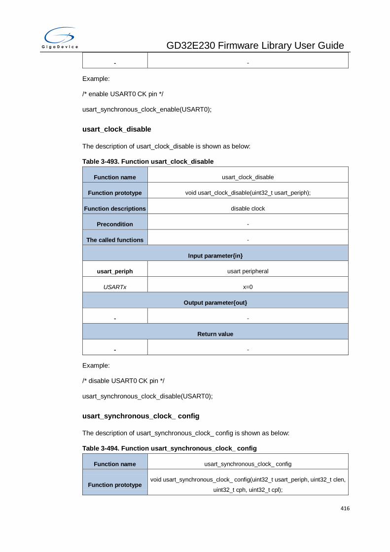
GD32E230 Firmware Library User Guide
416
- -
Example:
/* enable USART0 CK pin */
usart_synchronous_clock_enable(USART0);
usart_clock_disable
The description of usart_clock_disable is shown as below:
Table 3-493. Function usart_clock_disable
Function name usart_clock_disable
Function prototype void usart_clock_disable(uint32_t usart_periph);
Function descriptions disable clock
Precondition -
The called functions -
Input parameter{in}
usart_periph usart peripheral
USARTx x=0
Output parameter{out}
- -
Return value
- -
Example:
/* disable USART0 CK pin */
usart_synchronous_clock_disable(USART0);
usart_synchronous_clock_ config
The description of usart_synchronous_clock_ config is shown as below:
Table 3-494. Function usart_synchronous_clock_ config
Function name usart_synchronous_clock_ config
Function prototype void usart_synchronous_clock_ config(uint32_t usart_periph, uint32_t clen,
uint32_t cph, uint32_t cpl);

GD32E230 Firmware Library User Guide
417
Function descriptions configure USART synchronous mode parameters
Precondition -
The called functions -
Input parameter{in}
usart_periph usart peripheral
USARTx x=0,1
Input parameter{in}
clen last bit clock pulse
USART_CLEN_NONE clock pulse of the last data bit (MSB) is not output to the CK pin
USART_CLEN_EN clock pulse of the last data bit (MSB) is output to the CK pin
Input parameter{in}
cph clock phase
USART_CPH_1CK first clock transition is the first data capture edge
USART_CPH_2CK second clock transition is the first data capture edge
Input parameter{in}
cpl clock polarity
USART_CPL_LOW steady low value on CK pin
USART_CPL_HIGH steady high value on CK pin
Output parameter{out}
- -
Return value
- -
Example:
/* configure USART0 synchronous mode parameters */
usart_synchronous_clock_config(USART0,USART_CLEN_EN,USART_CPH_2CK,
USART_CPL_HIGH);
usart_guard_time_config
The description of usart_guard_time_config is shown as below:
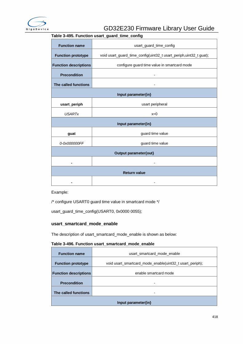
GD32E230 Firmware Library User Guide
418
Table 3-495. Function usart_guard_time_config
Function name usart_guard_time_config
Function prototype void usart_guard_time_config(uint32_t usart_periph,uint32_t guat);
Function descriptions configure guard time value in smartcard mode
Precondition -
The called functions -
Input parameter{in}
usart_periph usart peripheral
USARTx x=0
Input parameter{in}
guat guard time value
0-0x000000FF guard time value
Output parameter{out}
- -
Return value
- -
Example:
/* configure USART0 guard time value in smartcard mode */
usart_guard_time_config(USART0, 0x0000 0055);
usart_smartcard_mode_enable
The description of usart_smartcard_mode_enable is shown as below:
Table 3-496. Function usart_smartcard_mode_enable
Function name usart_smartcard_mode_enable
Function prototype void usart_smartcard_mode_enable(uint32_t usart_periph);
Function descriptions enable smartcard mode
Precondition -
The called functions -
Input parameter{in}

GD32E230 Firmware Library User Guide
419
usart_periph usart peripheral
USARTx x=0
Output parameter{out}
- -
Return value
- -
Example:
/* USART0 smartcard mode enable */
usart_smartcard_mode_enable(USART0);
usart_smartcard_mode_disable
The description of usart_smartcard_mode_disable is shown as below:
Table 3-497. Function usart_smartcard_mode_disable
Function name usart_smartcard_mode_disable
Function prototype void usart_smartcard_mode_disable(uint32_t usart_periph);
Function descriptions disable smartcard mode
Precondition -
The called functions -
Input parameter{in}
usart_periph usart peripheral
USARTx x=0
Output parameter{out}
- -
Return value
- -
Example:
/* USART0 smartcard mode disable */
usart_smartcard_mode_disable(USART0);
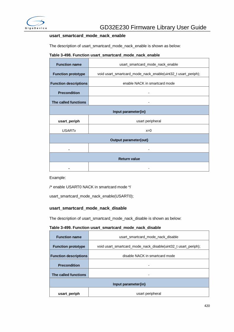
GD32E230 Firmware Library User Guide
420
usart_smartcard_mode_nack_enable
The description of usart_smartcard_mode_nack_enable is shown as below:
Table 3-498. Function usart_smartcard_mode_nack_enable
Function name usart_smartcard_mode_nack_enable
Function prototype void usart_smartcard_mode_nack_enable(uint32_t usart_periph);
Function descriptions enable NACK in smartcard mode
Precondition -
The called functions -
Input parameter{in}
usart_periph usart peripheral
USARTx x=0
Output parameter{out}
- -
Return value
- -
Example:
/* enable USART0 NACK in smartcard mode */
usart_smartcard_mode_nack_enable(USART0);
usart_smartcard_mode_nack_disable
The description of usart_smartcard_mode_nack_disable is shown as below:
Table 3-499. Function usart_smartcard_mode_nack_disable
Function name usart_smartcard_mode_nack_disable
Function prototype void usart_smartcard_mode_nack_disable(uint32_t usart_periph);
Function descriptions disable NACK in smartcard mode
Precondition -
The called functions -
Input parameter{in}
usart_periph usart peripheral

GD32E230 Firmware Library User Guide
421
USARTx x=0
Output parameter{out}
- -
Return value
- -
Example:
/* disable USART0 NACK in smartcard mode */
usart_smartcard_mode_nack_disable(USART0);
usart_smartcard_mode_early_nack_enable
The description of usart_smartcard_mode_early_nack_enable is shown as below:
Table 3-500. Function usart_smartcard_mode_early_nack_enable
Function name usart_smartcard_mode_early_nack_enable
Function prototype void usart_smartcard_mode_early_nack_enable(uint32_t usart_periph);
Function descriptions enable early NACK in smartcard mode
Precondition -
The called functions -
Input parameter{in}
usart_periph usart peripheral
USARTx x=0
Output parameter{out}
- -
Return value
- -
Example:
/* enable USART0 early NACK in smartcard mode */
usart_smartcard_mode_early_nack_enable(USART0);
usart_smartcard_mode_early_nack_disable
The description of usart_smartcard_mode_early_nack_disable is shown as below:

GD32E230 Firmware Library User Guide
422
Table 3-501. Function usart_smartcard_mode_early_nack_disable
Function name usart_smartcard_mode_early_nack_disable
Function prototype void usart_smartcard_mode_early_nack_disable(uint32_t usart_periph);
Function descriptions disable early NACK in smartcard mode
Precondition -
The called functions -
Input parameter{in}
usart_periph usart peripheral
USARTx x=0
Output parameter{out}
- -
Return value
- -
Example:
/* disable USART0 early NACK in smartcard mode */
usart_smartcard_mode_early_nack_disable(USART0);
usart_smartcard_autoretry_config
The description of usart_smartcard_autoretry_config is shown as below:
Table 3-502. Function usart_smartcard_autoretry_config
Function name usart_smartcard_autoretry_config
Function prototype void usart_smartcard_autoretry_config(uint32_t usart_periph, uint32_t
scrtnum);
Function descriptions configure smartcard auto-retry number
Precondition -
The called functions -
Input parameter{in}
usart_periph usart peripheral
USARTx x=0
Input parameter{in}

GD32E230 Firmware Library User Guide
423
scrtnum smartcard auto-retry number
0x00000000-
0x00000007 smartcard auto-retry number
Output parameter{out}
- -
Return value
- -
Example:
/* configure smartcard auto-retry number */
usart_smartcard_autoretry_config(USART0, 0x00000007);
usart_block_length_config
The description of usart_block_length_config is shown as below:
Table 3-503. Function usart_block_length_config
Function name usart_block_length_config
Function prototype void usart_block_length_config(uint32_t usart_periph, uint32_t bl);
Function descriptions configure block length
Precondition -
The called functions -
Input parameter{in}
usart_periph usart peripheral
USARTx x=0
Input parameter{in}
bl block length
0-0x000000FF block length
Output parameter{out}
- -
Return value
- -
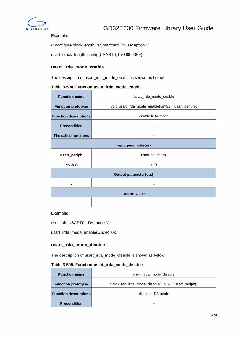
GD32E230 Firmware Library User Guide
424
Example:
/* configure block length in Smartcard T=1 reception */
usart_block_length_config(USART0, 0x000000FF);
usart_irda_mode_enable
The description of usart_irda_mode_enable is shown as below:
Table 3-504. Function usart_irda_mode_enable
Function name usart_irda_mode_enable
Function prototype void usart_irda_mode_enable(uint32_t usart_periph);
Function descriptions enable IrDA mode
Precondition -
The called functions -
Input parameter{in}
usart_periph usart peripheral
USARTx x=0
Output parameter{out}
- -
Return value
- -
Example:
/* enable USART0 IrDA mode */
usart_irda_mode_enable(USART0);
usart_irda_mode_disable
The description of usart_irda_mode_disable is shown as below:
Table 3-505. Function usart_irda_mode_disable
Function name usart_irda_mode_disable
Function prototype void usart_irda_mode_disable(uint32_t usart_periph);
Function descriptions disable IrDA mode
Precondition -
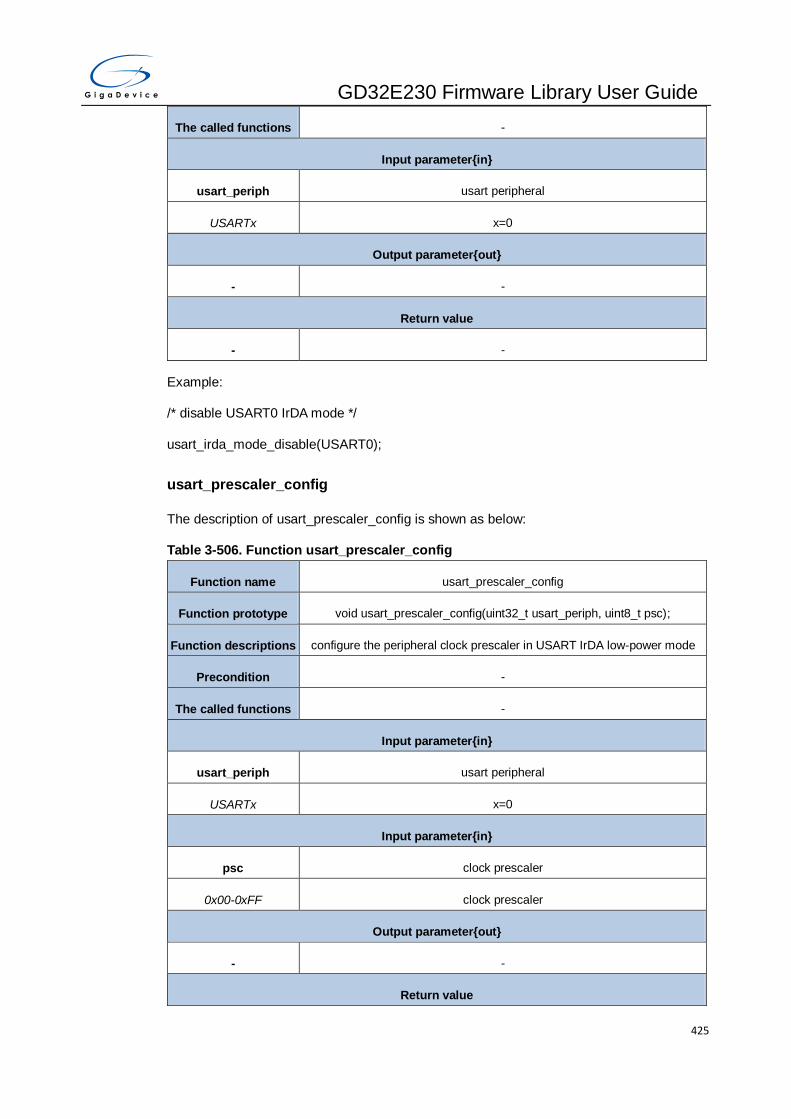
GD32E230 Firmware Library User Guide
425
The called functions -
Input parameter{in}
usart_periph usart peripheral
USARTx x=0
Output parameter{out}
- -
Return value
- -
Example:
/* disable USART0 IrDA mode */
usart_irda_mode_disable(USART0);
usart_prescaler_config
The description of usart_prescaler_config is shown as below:
Table 3-506. Function usart_prescaler_config
Function name usart_prescaler_config
Function prototype void usart_prescaler_config(uint32_t usart_periph, uint8_t psc);
Function descriptions configure the peripheral clock prescaler in USART IrDA low-power mode
Precondition -
The called functions -
Input parameter{in}
usart_periph usart peripheral
USARTx x=0
Input parameter{in}
psc clock prescaler
0x00-0xFF clock prescaler
Output parameter{out}
- -
Return value
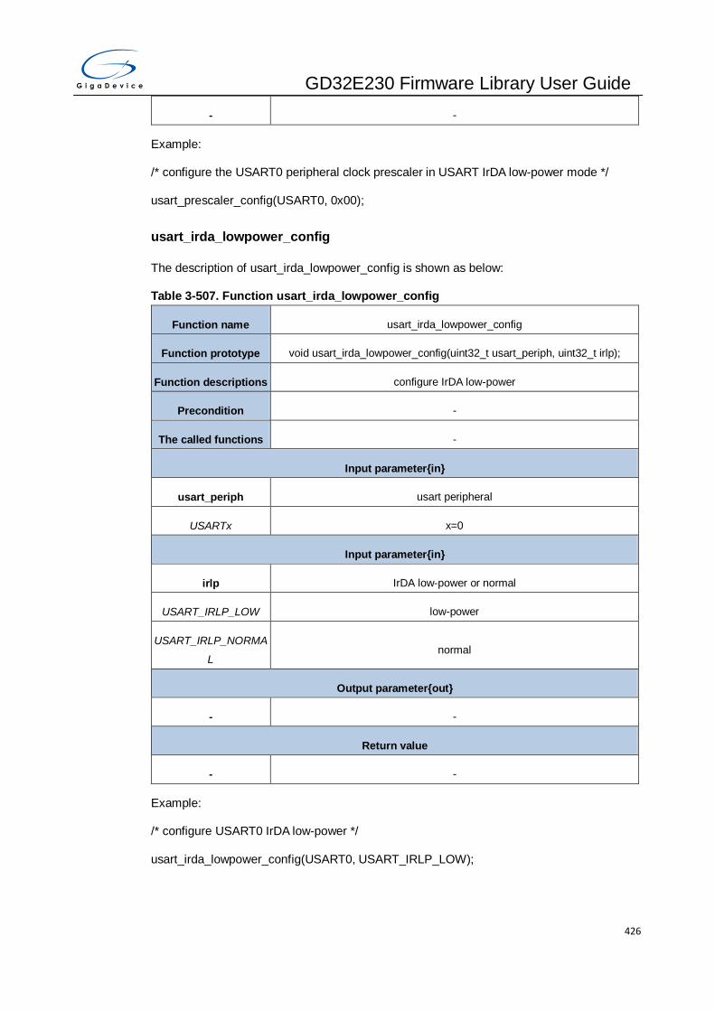
GD32E230 Firmware Library User Guide
426
- -
Example:
/* configure the USART0 peripheral clock prescaler in USART IrDA low-power mode */
usart_prescaler_config(USART0, 0x00);
usart_irda_lowpower_config
The description of usart_irda_lowpower_config is shown as below:
Table 3-507. Function usart_irda_lowpower_config
Function name usart_irda_lowpower_config
Function prototype void usart_irda_lowpower_config(uint32_t usart_periph, uint32_t irlp);
Function descriptions configure IrDA low-power
Precondition -
The called functions -
Input parameter{in}
usart_periph usart peripheral
USARTx x=0
Input parameter{in}
irlp IrDA low-power or normal
USART_IRLP_LOW low-power
USART_IRLP_NORMA
L normal
Output parameter{out}
- -
Return value
- -
Example:
/* configure USART0 IrDA low-power */
usart_irda_lowpower_config(USART0, USART_IRLP_LOW);
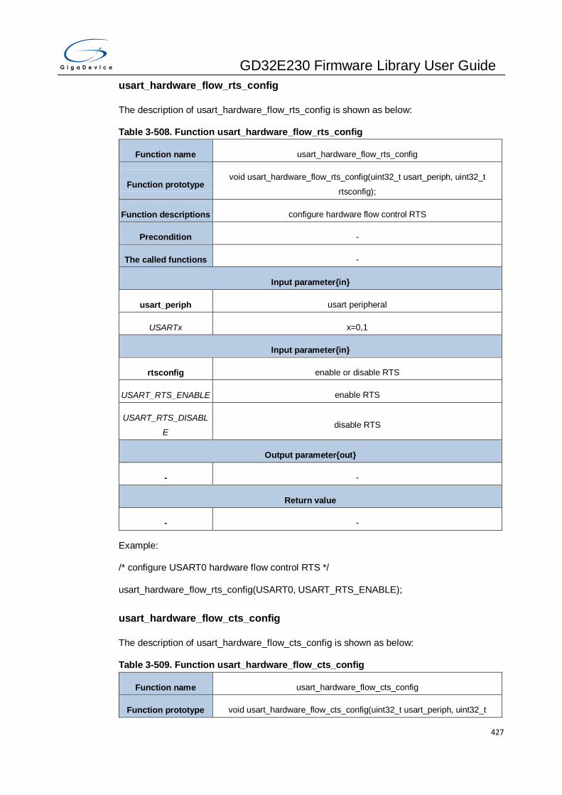
GD32E230 Firmware Library User Guide
427
usart_hardware_flow_rts_config
The description of usart_hardware_flow_rts_config is shown as below:
Table 3-508. Function usart_hardware_flow_rts_config
Function name usart_hardware_flow_rts_config
Function prototype void usart_hardware_flow_rts_config(uint32_t usart_periph, uint32_t
rtsconfig);
Function descriptions configure hardware flow control RTS
Precondition -
The called functions -
Input parameter{in}
usart_periph usart peripheral
USARTx x=0,1
Input parameter{in}
rtsconfig enable or disable RTS
USART_RTS_ENABLE enable RTS
USART_RTS_DISABL
E disable RTS
Output parameter{out}
- -
Return value
- -
Example:
/* configure USART0 hardware flow control RTS */
usart_hardware_flow_rts_config(USART0, USART_RTS_ENABLE);
usart_hardware_flow_cts_config
The description of usart_hardware_flow_cts_config is shown as below:
Table 3-509. Function usart_hardware_flow_cts_config
Function name usart_hardware_flow_cts_config
Function prototype void usart_hardware_flow_cts_config(uint32_t usart_periph, uint32_t

GD32E230 Firmware Library User Guide
428
ctsconfig);
Function descriptions configure hardware flow control RTS
Precondition -
The called functions -
Input parameter{in}
usart_periph usart peripheral
USARTx x=0,1
Input parameter{in}
ctsconfig enable or disable CTS
USART_CTS_ENABLE enable CTS
USART_CTS_DISABL
E disable CTS
Output parameter{out}
- -
Return value
- -
Example:
/* configure USART0 hardware flow control CTS */
usart_hardware_flow_cts_config(USART0, USART_CTS_ENABLE);
usart_hardware_flow_coherence_config
The description of usart_hardware_flow_coherence_config is shown as below:
Table 3-510. Function usart_hardware_flow_coherence_config
Function name usart_hardware_flow_coherence_config
Function prototype void usart_hardware_flow_coherence_config(uint32_t usart_periph, uint32_t
hcm);
Function descriptions configure hardware flow control coherence mode
Precondition -
The called functions -
Input parameter{in}

GD32E230 Firmware Library User Guide
429
usart_periph usart peripheral
USARTx x=0,1
Input parameter{in}
hcm Hardware flow control coherence mode
USART_HCM_NONE nRTS signal equals to the rxne status register
USART_HCM_EN nRTS signal is set when the last data bit has been sampled
Output parameter{out}
- -
Return value
- -
Example:
/* configure hardware flow control coherence mode */
usart_hardware_flow_coherence_config(USART0, USART_HCM_NONE);
usart_rs485_driver_enable
The description of usart_rs485_driver_enable is shown as below:
Table 3-511. Function usart_rs485_driver_enable
Function name usart_rs485_driver_enable
Function prototype void usart_rs485_driver_enable(uint32_t usart_periph);
Function descriptions enable USART RS485 driver
Precondition -
The called functions -
Input parameter{in}
usart_periph usart peripheral
USARTx x=0,1
Output parameter{out}
- -
Return value
- -

GD32E230 Firmware Library User Guide
430
Example:
/* enable USART0 RS485 driver */
usart_rs485_driver_enable(USART0);
usart_rs485_driver_disable
The description of usart_rs485_driver_disable is shown as below:
Table 3-512. Function usart_rs485_driver_disable
Function name usart_rs485_driver_disable
Function prototype void usart_rs485_driver_disable(uint32_t usart_periph);
Function descriptions disable USARTRS485 driver
Precondition -
The called functions -
Input parameter{in}
usart_periph usart peripheral
USARTx x=0,1
Output parameter{out}
- -
Return value
- -
Example:
/* disable USART0 RS485 driver */
usart_rs485_driver_disable (USART0);
usart_driver_assertime_config
The description of usart_driver_assertime_config is shown as below:
Table 3-513. Function usart_driver_assertime_config
Function name usart_driver_assertime_config
Function prototype void usart_driver_assertime_config(uint32_t usart_periph, uint32_t
deatime);
Function descriptions configure driver enable assertion time

GD32E230 Firmware Library User Guide
431
Precondition -
The called functions -
Input parameter{in}
usart_periph usart peripheral
USARTx x=0,1
Input parameter{in}
deatime driver enable assertion time
0-0x0000001F driver enable assertion time
Output parameter{out}
- -
Return value
- -
Example:
/* set USART0 driver assertime */
usart_driver_assertime_config(USART0,0x0000001F);
usart_driver_deassertime_config
The description of usart_driver_deassertime_config is shown as below:
Table 3-514. Function usart_driver_deassertime_config
Function name usart_driver_deassertime_config
Function prototype void usart_driver_deassertime_config(uint32_t usart_periph, uint32_t
dedtime);
Function descriptions configure driver enable de-assertion time
Precondition -
The called functions -
Input parameter{in}
usart_periph usart peripheral
USARTx x=0,1
Input parameter{in}
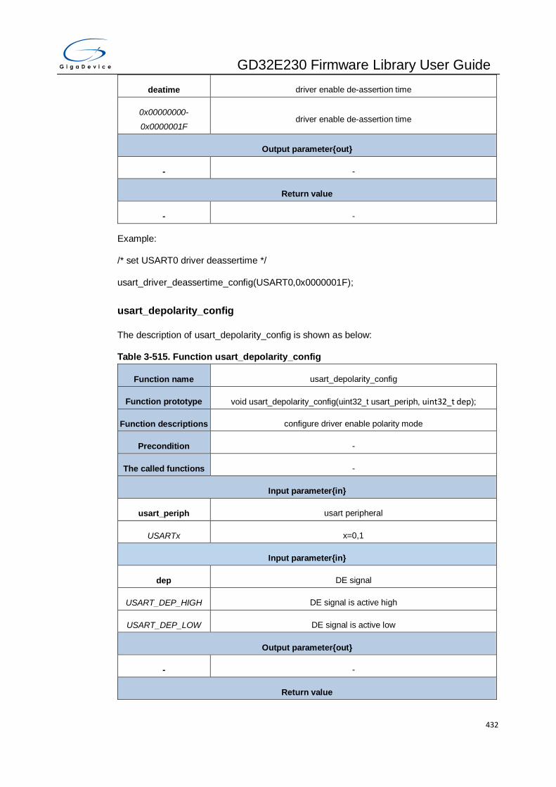
GD32E230 Firmware Library User Guide
432
deatime driver enable de-assertion time
0x00000000-
0x0000001F driver enable de-assertion time
Output parameter{out}
- -
Return value
- -
Example:
/* set USART0 driver deassertime */
usart_driver_deassertime_config(USART0,0x0000001F);
usart_depolarity_config
The description of usart_depolarity_config is shown as below:
Table 3-515. Function usart_depolarity_config
Function name usart_depolarity_config
Function prototype void usart_depolarity_config(uint32_t usart_periph, uint32_t dep);
Function descriptions configure driver enable polarity mode
Precondition -
The called functions -
Input parameter{in}
usart_periph usart peripheral
USARTx x=0,1
Input parameter{in}
dep DE signal
USART_DEP_HIGH DE signal is active high
USART_DEP_LOW DE signal is active low
Output parameter{out}
- -
Return value

GD32E230 Firmware Library User Guide
433
- -
Example:
//* configure driver enable polarity mode */
usart_driver_depolarity_config(USART0, USART_DEP_HIGH);
usart_dma_receive_config
The description of usart_dma_receive_config is shown as below:
Table 3-516. Function usart_dma_receive_config
Function name usart_dma_receive_config
Function prototype void usart_dma_receive_config(uint32_t usart_periph, uint32_t dmacmd);
Function descriptions configure USART DMA reception
Precondition -
The called functions -
Input parameter{in}
usart_periph usart peripheral
USARTx x=0,1
Input parameter{in}
dmacmd enable or disable DMA for reception
USART_DENR_ENABL
E DMA enable for reception
USART_DENR_DISAB
LE DMA disable for reception
Output parameter{out}
- -
Return value
- -
Example:
/* USART0 DMA enable for reception */
usart_dma_receive_config(USART0, USART_DENR_ENABLE);
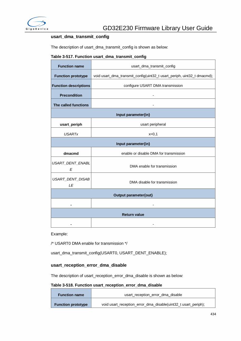
GD32E230 Firmware Library User Guide
434
usart_dma_transmit_config
The description of usart_dma_transmit_config is shown as below:
Table 3-517. Function usart_dma_transmit_config
Function name usart_dma_transmit_config
Function prototype void usart_dma_transmit_config(uint32_t usart_periph, uint32_t dmacmd);
Function descriptions configure USART DMA transmission
Precondition -
The called functions -
Input parameter{in}
usart_periph usart peripheral
USARTx x=0,1
Input parameter{in}
dmacmd enable or disable DMA for transmission
USART_DENT_ENABL
E DMA enable for transmission
USART_DENT_DISAB
LE DMA disable for transmission
Output parameter{out}
- -
Return value
- -
Example:
/* USART0 DMA enable for transmission */
usart_dma_transmit_config(USART0, USART_DENT_ENABLE);
usart_reception_error_dma_disable
The description of usart_reception_error_dma_disable is shown as below:
Table 3-518. Function usart_reception_error_dma_disable
Function name usart_reception_error_dma_disable
Function prototype void usart_reception_error_dma_disable(uint32_t usart_periph);

GD32E230 Firmware Library User Guide
435
Function descriptions disable DMA on reception error
Precondition -
The called functions -
Input parameter{in}
usart_periph usart peripheral
USARTx x=0,1
Output parameter{out}
- -
Return value
- -
Example:
/* disable DMA on reception error */
usart_reception_error_dma_disable(USART0);
usart_reception_error_dma_enable
The description of usart_reception_error_dma_enable is shown as below:
Table 3-519. Function usart_reception_error_dma_enable
Function name usart_reception_error_dma_enable
Function prototype void usart_reception_error_dma_enable(uint32_t usart_periph);
Function descriptions enable DMA on reception error
Precondition -
The called functions -
Input parameter{in}
usart_periph usart peripheral
USARTx x=0,1
Output parameter{out}
- -
Return value
- -

GD32E230 Firmware Library User Guide
436
Example:
/* enable DMA on reception error */
usart_reception_error_dma_ enable(USART0);
usart_wakeup_enable
The description of usart_wakeup_enable is shown as below:
Table 3-520. Function usart_wakeup_enable
Function name usart_wakeup_enable
Function prototype void usart_wakeup_enable(uint32_t usart_periph);
Function descriptions USART be able to wake up the MCU from deep-sleep mode
Precondition -
The called functions -
Input parameter{in}
usart_periph usart peripheral
USARTx x=0
Output parameter{out}
- -
Return value
- -
Example:
/* USART0 wake up enable */
usart_wakeup_enable(USART0);
usart_wakeup_disable
The description of usart_wakeup_disable is shown as below:
Table 3-521. Function usart_wakeup_disable
Function name usart_wakeup_disable
Function prototype void usart_wakeup_disable(uint32_t usart_periph);
Function descriptions USART not be able to wake up the MCU from deep-sleep mode
Precondition -

GD32E230 Firmware Library User Guide
437
The called functions -
Input parameter{in}
usart_periph usart peripheral
USARTx x=0
Output parameter{out}
- -
Return value
- -
Example:
/* USART0 wake up disable */
usart_wakeup_disable(USART0);
usart_wakeup_mode_config
The description of usart_wakeup_mode_config is shown as below:
Table 3-522. Function usart_wakeup_mode_config
Function name usart_wakeup_mode_config
Function prototype void usart_wakeup_mode_config(uint32_t usart_periph, uint32_t wum);
Function descriptions wakeup mode from deep-sleep mode
Precondition -
The called functions -
Input parameter{in}
usart_periph usart peripheral
USARTx x=0
Input parameter{in}
wum wakeup mode
USART_WUM_ADDR WUF active on address match
USART_WUM_START
B WUF active on start bit
USART_WUM_RBNE WUF active on RBNE

GD32E230 Firmware Library User Guide
438
Output parameter{out}
- -
Return value
- -
Example:
/* configure USART0 wake up mode */
usart_wakeup_mode_config(USART0, USART_WUM_ADDR);
usart_receive_fifo_enable
The description of usart_receive_fifo_enable is shown as below:
Table 3-523. Function usart_receive_fifo_enable
Function name usart_receive_fifo_enable
Function prototype void usart_receive_fifo_enable(uint32_t usart_periph);
Function descriptions enable receive FIFO
Precondition -
The called functions -
Input parameter{in}
usart_periph usart peripheral
USARTx x=0,1
Output parameter{out}
- -
Return value
- -
Example:
/* enable receive FIFO */
usart_receive_fifo_enable(USART0);
usart_receive_fifo_disable
The description of usart_receive_fifo_disable is shown as below:

GD32E230 Firmware Library User Guide
439
Table 3-524. Function usart_receive_fifo_disable
Function name usart_receive_fifo_disable
Function prototype void usart_receive_fifo_disable(uint32_t usart_periph);
Function descriptions disable receive FIFO
Precondition -
The called functions -
Input parameter{in}
usart_periph usart peripheral
USARTx x=0,1
Output parameter{out}
- -
Return value
- -
Example:
/* disable receive FIFO */
usart_receive_fifo_disable(USART0);
usart_receive_fifo_counter_number
The description of usart_receive_fifo_counter_number is shown as below:
Table 3-525. Function usart_receive_fifo_counter_number
Function name usart_receive_fifo_counter_number
Function prototype uint8_t usart_receive_fifo_counter_number(uint32_t usart_periph);
Function descriptions read receive FIFO counter number
Precondition -
The called functions -
Input parameter{in}
usart_periph usart peripheral
USARTx x=0,1
Output parameter{out}
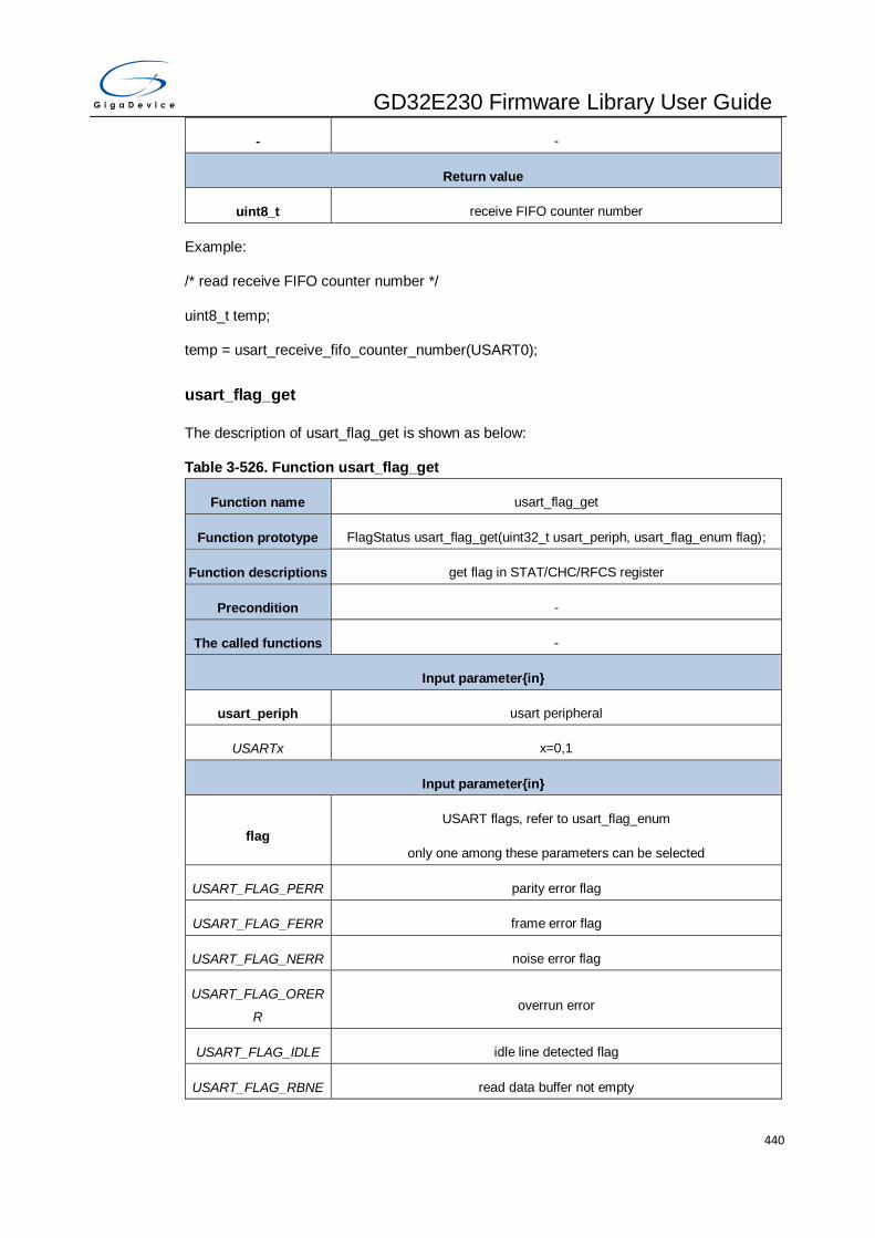
GD32E230 Firmware Library User Guide
440
- -
Return value
uint8_t receive FIFO counter number
Example:
/* read receive FIFO counter number */
uint8_t temp;
temp = usart_receive_fifo_counter_number(USART0);
usart_flag_get
The description of usart_flag_get is shown as below:
Table 3-526. Function usart_flag_get
Function name usart_flag_get
Function prototype FlagStatus usart_flag_get(uint32_t usart_periph, usart_flag_enum flag);
Function descriptions get flag in STAT/CHC/RFCS register
Precondition -
The called functions -
Input parameter{in}
usart_periph usart peripheral
USARTx x=0,1
Input parameter{in}
flag
USART flags, refer to usart_flag_enum
only one among these parameters can be selected
USART_FLAG_PERR parity error flag
USART_FLAG_FERR frame error flag
USART_FLAG_NERR noise error flag
USART_FLAG_ORER
R overrun error
USART_FLAG_IDLE idle line detected flag
USART_FLAG_RBNE read data buffer not empty

GD32E230 Firmware Library User Guide
441
USART_FLAG_TC transmission completed
USART_FLAG_TBE transmit data register empty
USART_FLAG_LBD LIN break detected flag
USART_FLAG_CTSF CTS change flag
USART_FLAG_CTS CTS level
USART_FLAG_RT receiver timeout flag
USART_FLAG_EB end of block flag
USART_FLAG_ABDE auto baudrate detection error
USART_FLAG_ABD auto baudrate detection flag
USART_FLAG_BSY busy flag
USART_FLAG_AM address match flag
USART_FLAG_SB send break flag
USART_FLAG_RWU receiver wakeup from mute mode
USART_FLAG_WU wakeup from deep-sleep mode flag
USART_FLAG_TEA transmit enable acknowledge flag
USART_FLAG_REA receive enable acknowledge flag
USART_FLAG_EPERR early parity error flag
USART_FLAG_RFE receive FIFO empty flag
USART_FLAG_RFF receive FIFO full flag
USART_FLAG_RFFINT receive FIFO full interrupt flag
Output parameter{out}
- -
Return value
FlagStatus SET or RESET
Example:
/* get flag USART0 state */
FlagStatus status;
status = usart_flag_get(USART0,USART_FLAG_TBE);

GD32E230 Firmware Library User Guide
442
usart_flag_clear
The description of usart_flag_clear is shown as below:
Table 3-527. Function usart_flag_clear
Function name usart_flag_clear
Function prototype void usart_flag_clear(uint32_t usart_periph, usart_flag_enum flag);
Function descriptions clear flag in STAT register
Precondition -
The called functions -
Input parameter{in}
usart_periph usart peripheral
USARTx x=0,1
Input parameter{in}
flag
USART flags, refer to usart_flag_enum
only one among these parameters can be selected
USART_FLAG_PERR parity error flag
USART_FLAG_FERR frame error flag
USART_FLAG_NERR noise detected flag
USART_FLAG_ORER
R overrun error flag
USART_FLAG_IDLE idle line detected flag
USART_FLAG_TC transmission complete flag
USART_FLAG_LBD LIN break detected flag
USART_FLAG_CTSF CTS change flag
USART_FLAG_RT receiver timeout flag
USART_FLAG_EB end of block flag
USART_FLAG_AM address match flag
USART_FLAG_WU wakeup from deep-sleep mode flag
USART_FLAG_EPERR early parity error flag
Output parameter{out}

GD32E230 Firmware Library User Guide
443
- -
Return value
- -
Example:
/* clear USART0 flag */
usart_flag_clear(USART0,USART_FLAG_TC);
usart_interrupt_enable
The description of usart_interrupt_enableis shown as below:
Table 3-528. Function usart_interrupt_enable
Function name usart_interrupt_enable
Function prototype void usart_interrupt_enable(uint32_t usart_periph, usart_interrupt_enum
inttype);
Function descriptions enable USART interrupt
Precondition -
The called functions -
Input parameter{in}
usart_periph usart peripheral
USARTx x=0,1
Input parameter{in}
inttype interrupt type
USART_INT_IDLE idle interrupt
USART_INT_RBNE read data buffer not empty interrupt and overrun error interrupt enable
interrupt
USART_INT_TC transmission complete interrupt
USART_INT_TBE transmit data register empty interrupt
USART_INT_PERR parity error interrupt
USART_INT_AM address match interrupt
USART_INT_RT receiver timeout interrupt
USART_INT_EB end of block interrupt

GD32E230 Firmware Library User Guide
444
USART_INT_LBD LIN break detection interrupt
USART_INT_ERR error interrupt enable in multibuffer communication
USART_INT_CTS CTS interrupt
USART_INT_WU wakeup from deep-sleep mode interrupt
USART_INT_RFF receive FIFO full interrupt enable
Output parameter{out}
- -
Return value
- -
Example:
/* enable USART0 TBE interrupt */
usart_interrupt_enable(USART0, USART_INT_TBE);
usart_interrupt_disable
The description of usart_interrupt_disable is shown as below:
Table 3-529. Function usart_interrupt_disable
Function name usart_interrupt_disable
Function prototype void usart_interrupt_disable(uint32_t usart_periph, usart_interrupt_enum
inttype);
Function descriptions disable USART interrupt
Precondition -
The called functions -
Input parameter{in}
usart_periph usart peripheral
USARTx x=0,1
Input parameter{in}
inttype USART interrupt flag
USART_INT_IDLE idle interrupt
USART_INT_RBNE read data buffer not empty interrupt and overrun error interrupt enable
interrupt
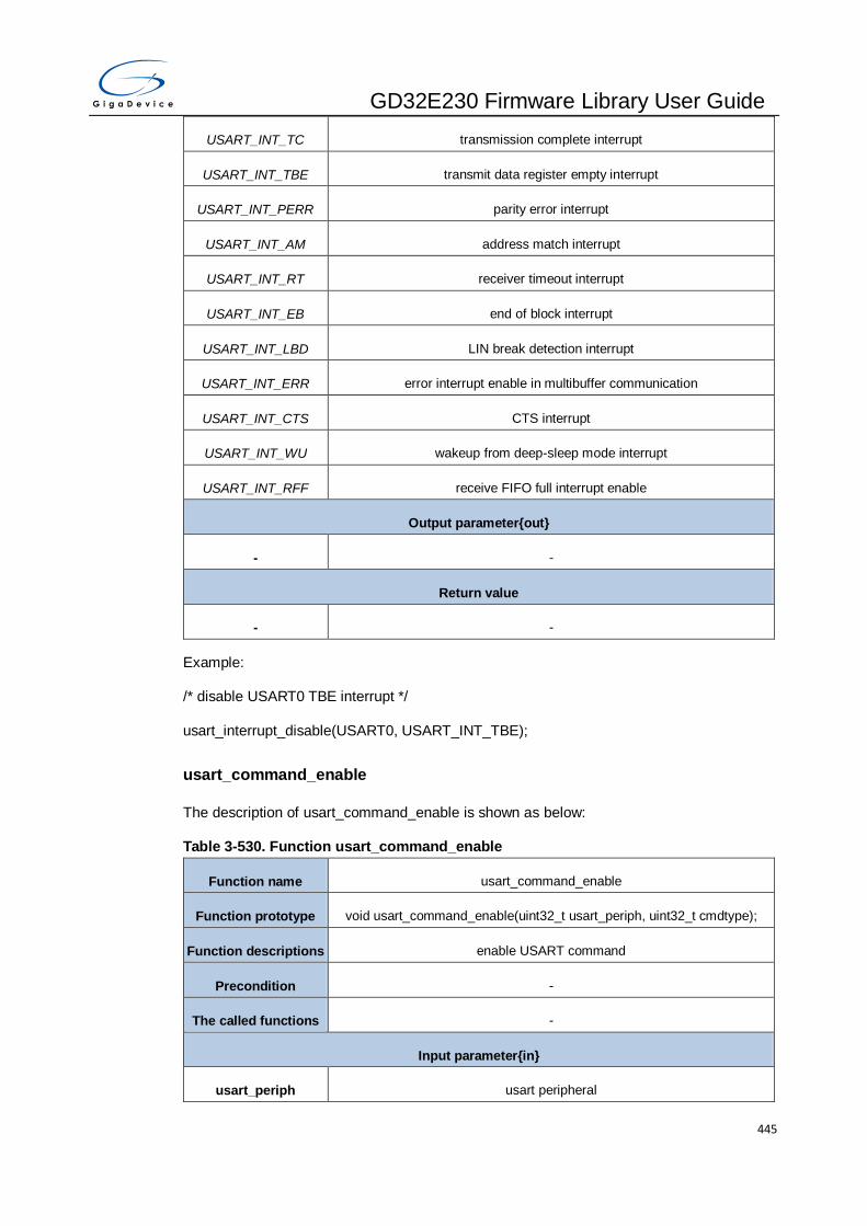
GD32E230 Firmware Library User Guide
445
USART_INT_TC transmission complete interrupt
USART_INT_TBE transmit data register empty interrupt
USART_INT_PERR parity error interrupt
USART_INT_AM address match interrupt
USART_INT_RT receiver timeout interrupt
USART_INT_EB end of block interrupt
USART_INT_LBD LIN break detection interrupt
USART_INT_ERR error interrupt enable in multibuffer communication
USART_INT_CTS CTS interrupt
USART_INT_WU wakeup from deep-sleep mode interrupt
USART_INT_RFF receive FIFO full interrupt enable
Output parameter{out}
- -
Return value
- -
Example:
/* disable USART0 TBE interrupt */
usart_interrupt_disable(USART0, USART_INT_TBE);
usart_command_enable
The description of usart_command_enable is shown as below:
Table 3-530. Function usart_command_enable
Function name usart_command_enable
Function prototype void usart_command_enable(uint32_t usart_periph, uint32_t cmdtype);
Function descriptions enable USART command
Precondition -
The called functions -
Input parameter{in}
usart_periph usart peripheral
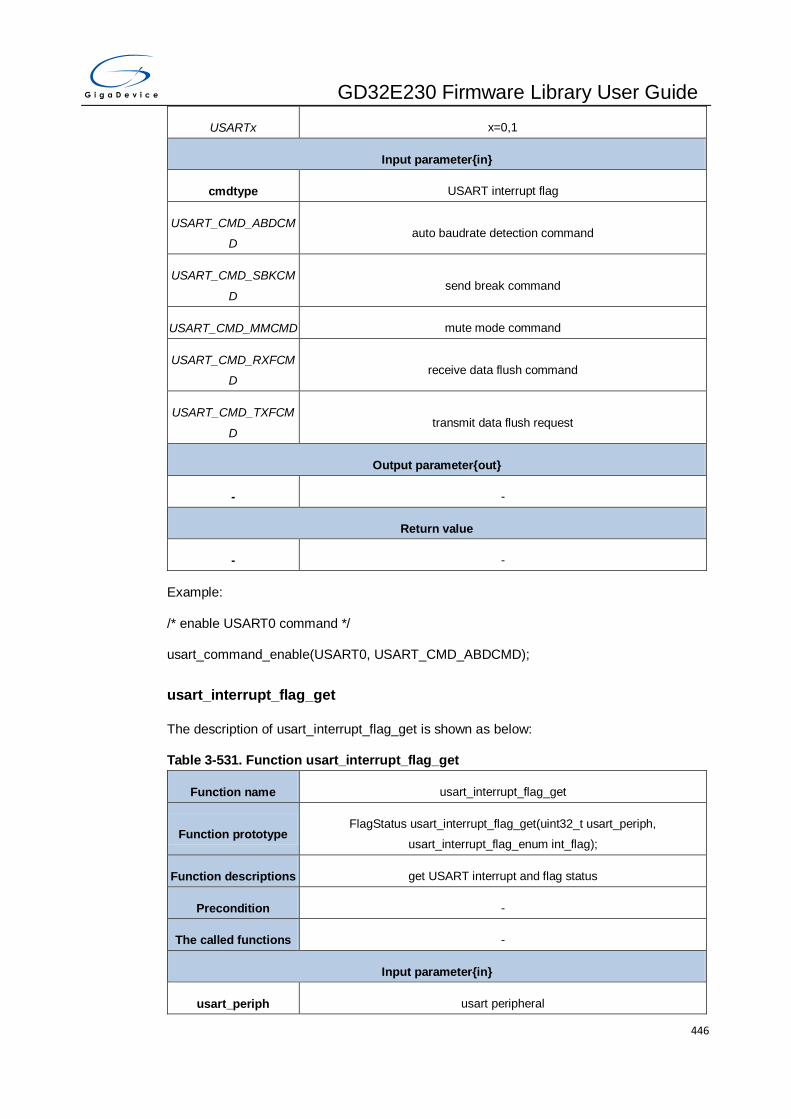
GD32E230 Firmware Library User Guide
446
USARTx x=0,1
Input parameter{in}
cmdtype USART interrupt flag
USART_CMD_ABDCM
D auto baudrate detection command
USART_CMD_SBKCM
D send break command
USART_CMD_MMCMD mute mode command
USART_CMD_RXFCM
D receive data flush command
USART_CMD_TXFCM
D transmit data flush request
Output parameter{out}
- -
Return value
- -
Example:
/* enable USART0 command */
usart_command_enable(USART0, USART_CMD_ABDCMD);
usart_interrupt_flag_get
The description of usart_interrupt_flag_get is shown as below:
Table 3-531. Function usart_interrupt_flag_get
Function name usart_interrupt_flag_get
Function prototype FlagStatus usart_interrupt_flag_get(uint32_t usart_periph,
usart_interrupt_flag_enum int_flag);
Function descriptions get USART interrupt and flag status
Precondition -
The called functions -
Input parameter{in}
usart_periph usart peripheral

GD32E230 Firmware Library User Guide
447
USARTx x=0,1
Input parameter{in}
int_flag USART interrupt flag
USART_INT_FLAG_EB end of block interrupt and flag
USART_INT_FLAG_RT receiver timeout interrupt and flag
USART_INT_FLAG_A
M address match interrupt and flag
USART_INT_FLAG_PE
RR parity error interrupt and flag
USART_INT_FLAG_TB
E transmitter buffer empty interrupt and flag
USART_INT_FLAG_TC transmission complete interrupt and flag
USART_INT_FLAG_RB
NE read data buffer not empty interrupt and flag
USART_INT_FLAG_RB
NE_ORERR read data buffer not empty interrupt and overrun error flag
USART_INT_FLAG_ID
LE IDLE line detected interrupt and flag
USART_INT_FLAG_LB
D LIN break detected interrupt and flag
USART_INT_FLAG_W
U wakeup from deep-sleep mode interrupt and flag
USART_INT_FLAG_CT
S CTS interrupt and flag
USART_INT_FLAG_ER
R_NERR error interrupt and noise error flag
USART_INT_FLAG_ER
R_ORERR error interrupt and overrun error
USART_INT_FLAG_ER
R_FERR error interrupt and frame error flag
USART_INT_FLAG_RF
F receive FIFO full interrupt and flag
Output parameter{out}

GD32E230 Firmware Library User Guide
448
- -
Return value
FlagStatus SET or RESET
Example:
/* get the USART0 interrupt flag status */
FlagStatus status;
status = usart_interrupt_flag_get(USART0, USART_INT_FLAG_RBNE);
usart_interrupt_flag_clear
The description of usart_interrupt_flag_clear is shown as below:
Table 3-532. Function usart_interrupt_flag_clear
Function name usart_interrupt_flag_clear
Function prototype void usart_interrupt_flag_clear(uint32_t usart_periph,
usart_interrupt_flag_enum flag);
Function descriptions clear USART interrupt flag in STAT register
Precondition -
The called functions -
Input parameter{in}
usart_periph usart peripheral
USARTx x=0,1
Input parameter{in}
flag USART interrupt flag
USART_INT_FLAG_PE
RR parity error flag
USART_INT_FLAG_ER
R_FERR frame error flag
USART_INT_FLAG_ER
R_NERR noise detected flag
USART_INT_FLAG_RB
NE_ORERR read data buffer not empty interrupt and overrun error flag
USART_INT_FLAG_ER error interrupt and overrun error
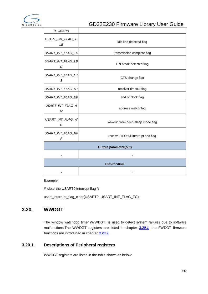
GD32E230 Firmware Library User Guide
449
R_ORERR
USART_INT_FLAG_ID
LE idle line detected flag
USART_INT_FLAG_TC transmission complete flag
USART_INT_FLAG_LB
D LIN break detected flag
USART_INT_FLAG_CT
S CTS change flag
USART_INT_FLAG_RT receiver timeout flag
USART_INT_FLAG_EB end of block flag
USART_INT_FLAG_A
M address match flag
USART_INT_FLAG_W
U wakeup from deep-sleep mode flag
USART_INT_FLAG_RF
F receive FIFO full interrupt and flag
Output parameter{out}
- -
Return value
- -
Example:
/* clear the USART0 interrupt flag */
usart_interrupt_flag_clear(USART0, USART_INT_FLAG_TC);
3.20. WWDGT
The window watchdog timer (WWDGT) is used to detect system failures due to software
malfunctions.The WWDGT registers are listed in chapter 3.20.1, the FWDGT firmware
functions are introduced in chapter 3.20.2.
3.20.1. Descriptions of Peripheral registers
WWDGT registers are listed in the table shown as below:

GD32E230 Firmware Library User Guide
450
Table 3-533. WWDGT Registers
Registers Descriptions
WWDGT_CTL Control register
WWDGT_CFG Configuration register
WWDGT_STAT Status register
3.20.2. Descriptions of Peripheral functions
WWDGT firmware functions are listed in the table shown as below:
Table 3-534. WWDGT firmware function
Function name Function description
wwdgt_deinit reset the WWDGT counter configuration
wwdgt_enable start the WWDGT counter
wwdgt_counter_update configure the WWDGT counter value
wwdgt_config configure counter value, window value, and prescaler divider
value
wwdgt_interrupt_enable enable early wakeup interrupt of WWDGT
wwdgt_flag_get check early wakeup interrupt state of WWDGT
wwdgt_flag_clear clear early wakeup interrupt state of WWDGT
wwdgt_deinit
The description of wwdgt_deinit is shown as below:
Table 3-535. Function wwdgt_deinit
Function name wwdgt_deinit
Function prototype void wwdgt_deinit(void);
Function descriptions reset the WWDGT counter configuration
Precondition -
The called functions -
Input parameter{in}
- -
Output parameter{out}

GD32E230 Firmware Library User Guide
451
- -
Return value
- -
Example:
/* reset the WWDGT configuration */
wwdgt_deinit ( );
wwdgt_enable
The description of wwdgt_enable is shown as below:
Table 3-536. Function wwdgt_enable
Function name wwdgt_enable
Function prototype void wwdgt_enable (void);
Function descriptions start the WWDGT counter
Precondition -
The called functions -
Input parameter{in}
- -
Output parameter{out}
- -
Return value
- -
Example:
/* start the WWDGT counter */
wwdgt_enable ( );
wwdgt_counter_update
The description of wwdgt_counter_update is shown as below:
Table 3-537. Function wwdgt_counter_update
Function name wwdgt_counter_update
Function prototype void wwdgt_counter_update(uint16_t counter_value);

GD32E230 Firmware Library User Guide
452
Function descriptions configure the WWDGT counter value
Precondition -
The called functions -
Input parameter{in}
counter_value counter_value: 0x00000000 - 0x0000007F
Output parameter{out}
- -
Return value
- -
Example:
/* update WWDGT counter to 0x7F */
wwdgt_counter_update(127);
wwdgt_config
The description of wwdgt_config is shown as below:
Table 3-538. Function wwdgt_config
Function name wwdgt_config
Function prototype void wwdgt_config(uint16_t counter, uint16_t window, uint32_t prescaler);
Function descriptions configure counter value, window value, and prescaler divider value
Precondition -
The called functions -
Input parameter{in}
counter counter: 0x00000000 - 0x0000007F
Input parameter{in}
window window: 0x00000000 - 0x0000007F
Input parameter{in}
prescaler wwdgt prescaler value
WWDGT_CFG_PSC_D
IV1 the time base of WWDGT counter = (PCLK1/4096)/1

GD32E230 Firmware Library User Guide
453
WWDGT_CFG_PSC_D
IV2 the time base of WWDGT counter = (PCLK1/4096)/2
WWDGT_CFG_PSC_D
IV4 the time base of WWDGT counter = (PCLK1/4096)/4
WWDGT_CFG_PSC_D
IV8 the time base of WWDGT counter = (PCLK1/4096)/8
Output parameter{out}
- -
Return value
- -
Example:
/* confiure WWDGT counter value to 0x7F, window value to 0x50, prescaler divider value to
8 */
wwdgt_config(127, 80, WWDGT_CFG_PSC_DIV8);
wwdgt_interrupt_enable
The description of wwdgt_interrupt_enable is shown as below:
Table 3-539. Function wwdgt_interrupt_enable
Function name wwdgt_interrupt_enable
Function prototype void wwdgt_interrupt_enable(void);
Function descriptions enable early wakeup interrupt of WWDGT
Precondition -
The called functions -
Input parameter{in}
- -
Output parameter{out}
- -
Return value
- -
Example:
/* enable early wakeup interrupt of WWDGT */

GD32E230 Firmware Library User Guide
454
wwdgt_interrupt_enable ( );
wwdgt_flag_get
The description of wwdgt_flag_get is shown as below:
Table 3-540. Function wwdgt_flag_get
Function name wwdgt_flag_get
Function prototype FlagStatus wwdgt_flag_get(void);
Function descriptions check early wakeup interrupt state of WWDGT
Precondition -
The called functions -
Input parameter{in}
- -
Output parameter{out}
- -
Return value
FlagStatus SET or RESET
Example:
/* test if the counter value update has reached the 0x40 */
FlagStatus status;
status = wwdgt_flag_get ( );
if(status == RESET)
{
...
}else
{
...
}
wwdgt_flag_clear
The description of wwdgt_flag_clear is shown as below:

GD32E230 Firmware Library User Guide
455
Table 3-541. Function wwdgt_flag_clear
Function name wwdgt_flag_clear
Function prototype void wwdgt_flag_clear(void);
Function descriptions clear early wakeup interrupt state of WWDGT
Precondition -
The called functions -
Input parameter{in}
- -
Output parameter{out}
- -
Return value
- -
Example:
/* clear early wakeup interrupt state of WWDGT */
wwdgt_flag_clear( );

GD32E230 Firmware Library User Guide
456
4. Revision history
Table 4-1. Revision history
Revison No. Description Date
1.0 Initial Release Aug.16, 2018
GD32E230 Firmware Library User Guide
457
Important Notice
This document is the property of GigaDevice Semiconductor Inc. and its subsidiaries (the "Company"). This document, including any
product of the Company described in this document (the “Product”), is owned by the Company under the intellectual property laws and
treaties of the People’s Republic of China and other jurisdictions worldwide. The Company reserves all rights under such laws and
treaties and does not grant any license under its patents, copyrights, trademarks, or other intellectual property rights. The names and
brands of third party referred thereto (if any) are the property of their respective owner and referred to for identification purposes only.
The Company makes no warranty of any kind, express or implied, with regard to this document or any Product, including, but no t
limited to, the implied warranties of merchantability and fitness for a particular purpose. The Company does not assume any liability
arising out of the application or use of any Product described in this document. Any information provided in this document is provided
only for reference purposes. It is the responsibility of the user of this document to properly design, program, and test the functionality
and safety of any application made of this information and any resulting product. Except for customized products which has been
expressly identified in the applicable agreement, the Products are designed, developed, and/or manufactured for ordinary business,
industrial, personal, and/or household applications only. The Products are not designed, intended, or authorized for use as components
in systems designed or intended for the operation of weapons, weapons systems, nuclear installations, atomic energy control
instruments, combustion control instruments, airplane or spaceship instruments, transportation instruments, traffic signal instruments,
life-support devices or systems, other medical devices or systems (including resuscitation equipment and surgical implants), pollution
control or hazardous substances management, or other uses where the failure of the device or Product could cause personal injury,
death, property or environmental damage ("Unintended Uses"). Customers shall take any and all actions to ensure using and selling
the Products in accordance with the applicable laws and regulations. The Company is not liable, in whole or in part, and customers
shall and hereby do release the Company as well as it’s suppliers and/or distributors from any claim, damage, or other liability arising
from or related to all Unintended Uses of the Products. Customers shall indemnify and hold the Company as well as it’s suppliers
and/or distributors harmless from and against all claims, costs, damages, and other liabilities, including claims for personal injury or
death, arising from or related to any Unintended Uses of the Products.
Information in this document is provided solely in connection with the Products. The Company reserves the right to make changes,
corrections, modifications or improvements to this document and Products and services described herein at any time, without notice.
© 2018 GigaDevice – All rights reserved