ghg 410 7001 p0001 d/e/f (r)
TRANSCRIPT
Explosionsgeschützte Steuergeräte GHG 411 und GHG 412
Explosion-protected control units GHG 411 and GHG 412
Boites de commande GHG 411 et GHG 412 pour atmosphères explosives
BetriebsanleitungOperating instructionsMode d’emploi
22
GHG 410 7001 P0001 D/E/F (r)
CROUSE-HINDSSERIES

2
Explosionsgeschützte Steuergeräte GHG 411 und GHG 412
Explosion-protected control units GHG 411 and GHG 412
Boites de commande GHG 411 et GHG 412 pour atmosphères explosives
1 Technische Angaben ................................ 3
1.1 Komplette Steuergeräte ........................... 3
1.2 Drucktaster-, Schalter- und Potentiometersockel allgemein ............... 3
1.2.1 Drucktastersockel 2 polig für Drucktaster, Schlagtaster, Schalter und Schlüsseltaster .................................. 4
1.2.2 Drucktastersockel 4 polig für Drucktaster, Schlagtaster, Schalter und Schlüsseltaster .................................. 4
1.2.3 Potentiometer .......................................... 4
1.3 Signallampe.............................................. 4
1.4 Messinstrument AM45 / AM72 ............... 5
Messinstrument VM45 / VM72 ............... 5
1.5 Klemmenblock ......................................... 5
1.6 Eigensichere Stromkreise ........................ 5
2 Sicherheitshinweise ................................. 6
3 Normenkonformität .................................. 6
4 Verwendungsbereich ............................... 6
5 Verwendung / Eigenschaften ................... 6
6 Installation ................................................ 7
6.1 Montage / Demontage ............................. 7
6.2 Öffnen des Gerätes/ .................................. Elektrischer Anschluss ............................. 7
6.3 Kabel- und Leitungseinführungen (KLE); Verschlussstopfen .................................... 8
6.4 Flansche und Metallplatten *................... 8
6.5 Schließen des Gerätes / Deckelverschluss ..................................... 8
6.6 Inbetriebnahme ........................................ 9
7 Instandhaltung / Wartung ......................... 9
8 Reparatur / Instandsetzung / Änderung ................................................. 9
9 Entsorgung /............................................... Wiederverwertung ................................... 9
Inhalt: Contents: Contenu:
1 Technical data..........................................10
1.1 Control unit assemblies ..........................10
1.2 Actuator general ......................................10
1.2.1 Actuator 2 pole for push button, Mushroom head p.b., switch and Key-operated pushbutton ........................11
1.2.2 Actuator 4 pole for push button, Mushroom head p.b., switch and Key-operated pushbutton ........................11
1.2.3 Potentiometer .........................................11
1.3 Signallamp...............................................11
1.4 AM45 / AM72 measuring Instrument VM45 / VM72 measuring instrument..... 12
1.5 Terminal block ........................................ 12
1.6 Intrinsically safe circuits: ........................ 12
2 Safety instructions ................................. 13
3 Conformity with standards .................... 13
4 Field of application ................................. 13
5 Application / Properties .......................... 13
6 Installation .............................................. 14
6.1 Mounting................................................ 14
6.2 Opening apparatus/ .................................... Electrical connection .............................. 14
6.3 Cable entries (KLE); ................................... blanking plugs ........................................ 15
6.4 Flange and metal plates ........................ 15
6.5 Closing apparatus / .................................... Cover closure ......................................... 15
6.6 Putting into operation ............................. 15
7 Maintenance / Servicing......................... 16
8 Repairs / Overhaul / .................................... Modification ........................................... 16
9 Disposal / Recycling ................................................ 16
1 Caractéristiques techniques ...................17
1.1 Boites de commande complete..............17
1.2 Modules général ....................................17
1.2.1 Bouton-poussoir 2 pole et interrupteurer 1.2.2 Bouton-poussoir 4 pole et interrupteur .................................18
1.2.3 Potentiomètre .........................................18
1.3 Lampe de signalisation ...........................18
1.4 Instrument de mesure AM45 / AM72 Instrument de mesure VM45 / VM72 .....19
1.5 Bornier ....................................................19
1.6 Circuit à sécurité intrinsèque ................................19
2 Consignes de sécurité ........................... 20
3 Conformité avec les normes .................. 20
4 Domaine d’utilisation ............................. 20
5 Utilisation / Propriétés ............................................... 20
6 Installation .............................................. 21
6.1 Montage................................................. 21
6.2 Ouverture de l’appareil / ............................. Raccordement électrique ....................... 21
6.3 Entrées de câble (KLE) / ............................. Bouchons de fermeture ......................... 22
6.4 Plaques à brides * .................................. 22
6.5 Fermeture de l’appareil / Fermeture à couvercle ........................... 22
6.6 Mise en service ...................................... 22
7 Maintien / Entretien ............................... 23
8 Réparations / Remise en état ................. 23
9 Évacuation des déchets / ........................... Recyclage ............................................... 23
Konformitätserklärung separat beigelegt. Declaration of conformity, enclosed separately. Déclaration de conformité, jointe séparément.
3
D
Explosionsgeschützte Steuergeräte GHG 411 und GHG 412
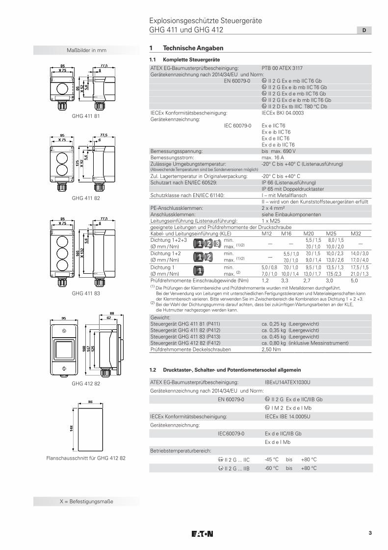
Maßbilder in mm
X = Befestigungsmaße
1 Technische Angaben
1.1 Komplette Steuergeräte
ATEX EG-Baumusterprüfbescheinigung: PTB 00 ATEX 3117Gerätekennzeichnung nach 2014/34/EU und Norm:
EN 60079-0 D II 2 G Ex e mb IIC T6 GbD II 2 G Ex e ib mb IIC T6 GbD II 2 G Ex d e mb IIC T6 GbD II 2 G Ex d e ib mb IIC T6 GbD II 2 D Ex tb IIIC T80 °C Db
IECEx Konformitätsbescheinigung: IECEx BKI 04.0003Gerätekennzeichnung:
IEC 60079-0 Ex e IIC T6Ex e ib IIC T6Ex d e IIC T6Ex d e ib IIC T6
Bemessungsspannung: bis max. 690 VBemessungsstrom: max. 16 AZulässige Umgebungstemperatur: (Abweichende Temperaturen sind bei Sonderversionen möglich)
-20° C bis +40° C (Listenausführung)
Zul. Lagertemperatur in Originalverpackung: -20° C bis +40° CSchutzart nach EN/IEC 60529: IP 66 (Listenausführung)
IP 65 mit DoppeldrucktasterSchutzklasse nach EN/IEC 61140: I – mit Metallflansch
II – wird von den Kunststoffsteuergeräten erfülltPE-Anschlussklemmen: 2 x 4 mm²Anschlussklemmen: siehe EinbaukomponentenLeitungseinführung (Listenausführung): 1 x M25geeignete Leitungen und Prüfdrehmomente der DruckschraubeKabel- und Leitungseinführung (KLE) M12 M16 M20 M25 M32Dichtung 1+2+3 (Ø mm / Nm) 1 2 3 min.
max. (1)(2) --- --- 5,5 / 1,5 7,0 / 1,0
8,0 / 1,5 10,0 / 2,0 ---
Dichtung 1+2 (Ø mm / Nm) 1 2 3 min.
max. (1)(2) --- 5,5 / 1,0 7,0 / 1,0
7,0 / 1,5 9,0 / 1,4
10,0 / 2,3 13,0 / 2,6
14,0 / 3,0 17,0 / 4,0
Dichtung 1 (Ø mm / Nm) 1 2 3 min.
max. (2)5,0 / 0,8 7,0 / 1,0
7,0 / 1,0 10,0 / 1,4
9,5 / 1,0 13,0 / 1,7
13,5 / 1,3 17,5 /2,3
17,5 / 1,5 21,0 / 1,3
Prüfdrehmomente Einschraubgewinde (Nm) 1,2 3,3 2,7 3,0 5,0(1) Die Prüfungen der Klemmbereiche und Prüfdrehmomente wurden mit Metalldornen durchgeführt.
Bei der Verwendung von Leitungen mit unterschiedlichen Fertigungstoleranzen und Materialeigenschaften kann der Klemmbereich variieren. Bitte verwenden Sie im Zwischenbereich die Kombination aus Dichtung 1 + 2 +3.
(2) Bei der Wahl der Dichtungsgummis darauf achten, dass bei zukünftigen Wartungsarbeiten an der KLE, die Hutmutter nachgezogen werden kann.
Gewicht:Steuergerät GHG 411 81 (P411) ca. 0,25 kg (Leergewicht)Steuergerät GHG 411 82 (P412) ca. 0,35 kg (Leergewicht)Steuergerät GHG 411 83 (P413) ca. 0,45 kg (Leergewicht)Steuergerät GHG 412 82 (F412) ca. 0,80 kg (inklusive Messinstrument)Prüfdrehmomente Deckelschrauben 2,50 Nm
GHG 411 81
GHG 411 82
GHG 411 83
GHG 412 82
Flanschausschnitt für GHG 412 82
ATEX EG-Baumusterprüfbescheinigung: IBExU14ATEX1030U
Gerätekennzeichnung nach 2014/34/EU und Norm:
EN 60079-0 D II 2 G Ex d e IIC/IIB Gb
D I M 2 Ex d e I Mb
IECEx Konformitätsbescheinigung: IECEx IBE 14.0005U
Gerätekennzeichnung:
IEC60079-0 Ex d e IIC/IIB Gb
Ex d e I Mb
Betriebstemperaturbereich:
II 2 G ... IIC -45 °C bis +80 °C
II 2 G ... IIB -60 °C bis +80 °C
1.2 Drucktaster-, Schalter- und Potentiometersockel allgemein

4
D
Explosionsgeschützte Steuergeräte GHG 411 und GHG 412
Maßbilder Bedienelemente 1.2.1 Drucktastersockel 2 polig für Drucktaster, Schlagtaster, Schalter und Schlüsseltaster
1.2.2 Drucktastersockel 4 polig für Drucktaster, Schlagtaster, Schalter und Schlüsseltaster
Bemessungsspannung: bis max. 500 VBemessungsstrom maximal
Bemessungsan-schlussquerschnitt
Umgebungstemperatur maximal
20 A 2,5 mm² 40 °C
16 A 4,0 mm² starr 40 °C
12 A 2,5 mm² 50 °C
15 A 4,0 mm² starr 50 °C
Schaltvermögen AC 15 (EN 60947-5-1): 250 V / 6 A 500 V / 4,0 A
Schaltvermögen DC 13 (EN 60947-5-1): 24 V / 6 A 60 V / 0,8 A 110 V / 0,5 A
mit Goldspitzkontakten: max. 400 mA
Anschlussklemmen: 2 x 1,0 - 2,5 mm²;
1 x 4,0 mm² starr
Prüfdrehmoment Anschlussklemmen 2,5 Nm
Gewicht: 2 polig ca. 0,15 kg
4 polig ca. 0,35 kg
1.2.3 Potentiometer
Bemessungsspannung: bis 250 VLeistung: 1 WDrehbereich: 270°Skalierung: 0 - 100%Anschlussklemme/Prüfdrehmoment: 2 x 1,0 - 2,5 mm²
1 x 4,0 mm² starrPrüfdrehmoment Anschlussklemmen 2,5 NmGewicht: ca. 0,15 kg
1.3 Signallampe
ATEX EG-Baumusterprüfbescheinigung: IBExU 12ATEX 1047 UGerätekennzeichnung nach 2014/34/EU und Norm:
EN 60079-0 D II 2 G Ex de IIC/IIB GbD II 2 G Ex d ia IIC/IIB Gb
IECEx Konformitätsbescheinigung: IECEx IBE 13.0031UGerätekennzeichnung:
IEC 60079-0 Ex d e IIC/IIB GbEx d ia IIC/IIB Gb
Betriebstemperaturbereich:D II 2 G Ex ... IIC -45 °C bis +60 °CD II 2 G Ex ... IIB -60 °C bis +60 °C
(Abweichende Temperaturen sind bei Sonderversionen möglich)
Bemessungsspannung/Bemessungsstrom:"e" erhöhte Sicherheit 20 V bis 254 V AC/DC 4 bis 15 mA"i" eigensichere Ausführung 10 V bis 30 V DC max. 25 mA"e" erhöhte Sicherheit 12 V bis 24 V AC/DC max. 24 mA
Ex-i Daten: U i 30 VI i 100 mACi 0Li 0Pi 750 mW
Anschlussklemmen: 2 x 1,0 - 2,5 mm²; 1 x 4,0 mm² starrPrüfdrehmoment Anschlussklemmen 2,5 NmGewicht: ca. 0,15 kg
Drucktastervorsatz
Doppeldrucktastervorsatz
Schlagtastervorsatz
Signalleuchtenvorsatz mit Kalotte
Schlagtastervorsatz „NOT-AUS“
Schlagtastervorsatz „NOT-AUS“ mit Schlüsselentriegelung
Schlüsselschalter*-/ tastervorsatz
* z.Zt. nicht bescheinigt für Kategorie II D

5
Maßbilder Bedienelemente
2
1
Messinstrumentenvorsatz AM/VM45
Messinstrumentenvorsatz AM/VM72
Schalter- und Potentiometervorsatz
X = Befestigungsmaße
Bild 1
D
Explosionsgeschützte Steuergeräte GHG 411 und GHG 412
1.5 Klemmenblock
1.4 Messinstrument AM45 / AM72
Messinstrument VM45/VM72
1.6 Eigensichere Stromkreise
Sicherheitstechnische Maximalspannung Um: 690 Veff
Galvanisch sicher getrennt von allen anderen Stromkreisen und von Erde
ATEX EG-Baumusterprüfbescheinigung: BVS 14 ATEX E 125U
Gerätekennzeichnung nach 2014/34/EU und Norm:
Dreheisen D II 2 G Ex e IIC Gb
D II 2 G Ex e mb IIC Gb
Drehspule D II 2 G Ex ib IIC Gb
IECEx Konformitätsbescheinigung: IECEx BVS 14.0082U
Gerätekennzeichnung:
Dreheisen Ex e IIC Gb
Ex e mb IIC Gb
Drehspule Ex ib IIC Gb
Betriebstemperaturbereich: -55 °C bis +80 °C
Bemessungsspannung: bis max. 500 V
Dreheisen Drehspule
Genauigkeit: Klasse 2,5 Klasse 1,5
Überlastbereich: fach sek. fach sek.
fach sek.
fach sek
anzeigend
Messbereiche:
direkt
Leistungsaufnahme:
Spule: Windungen
Innenwiderstand:
Li:
Ci:
Ui:
I i :
Anschlussklemmen: fein- / mehrdrähtig
eindrähtig
Prüfdrehmoment Anschlussklemme:
Gewicht AM/VM 45:
AM/VM 72:
EN 60079-0
IEC 60079-0
10 - - 25 10 - - 5
25 - - 4
50 - - 1
1:1,5
AM: n / 1A 0 - 24 mA
0 - 25 A 4 - 24 mA
VM45: 6 - 415 V
VM72: 6 - 660 V
VM45: 0,91 - 1,76 VA
VM72: 0,91 - 2,65 VA
26,5
2,5 Ohm +- 30%
- max. 0,1 mH
- max. 0,1 nF
- max. 30 V
- max. 150 mA
2 x 0,5 - 2,5 mm²
1 x 4,0 mm²
2,5 Nm
ca. 0,35 Kg
ca. 0,40 Kg
ATEX Konformitätsbescheinigung: SEV 13 ATEX 0178 U
Gerätekennzeichnung nach 2014/34/EU und Norm:
EN 60079-0 II 2 G Ex eb IIC
IECEx Zertifikat IECEx SEV 13.0012 U
Gerätekennzeichnung: IEC60079-0 Ex eb IIC
Klemmentyp: 6 x MUT 4
Bemessungsspannung: bis 352 V
Anschlussquerschnitt: 2 x 0,2 - 4,0 mm²
Prüfdrehmoment Anschlussklemmen: 0,6 - 0,8 Nm
Gewicht: ca. 0,08 kg
6
D
Explosionsgeschützte Steuergeräte GHG 411 und GHG 412
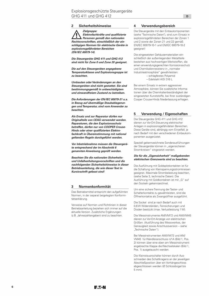
2 Sicherheitshinweise
aZielgruppe: Elektrofachkräfte und qualifizierte Personen gemäß den nationalen
Rechtsvorschriften, einschließlich der ein-schlägigen Normen für elektrische Geräte in explosionsgefährdeten Bereichen (EN/IEC 60079-14).
Die Steuergeräte GHG 411 und GHG 412 sind nicht für Zone 0 und Zone 20 geeignet.
Die auf den Steuergeräten angegebene Temperaturklasse und Explosionsgruppe ist zu beachten.
Umbauten oder Veränderungen an den Steuergeräten sind nicht gestattet. Sie sind bestimmungsgemäß in unbeschädigtem und einwandfreiem Zustand zu betreiben.
Die Anforderungen der EN/IEC 60079-31 u.a. in Bezug auf übermäßige Staubablagerun-gen und Temperatur, sind vom Anwender zu beachten.
Als Ersatz und zur Reparatur dürfen nur Originalteile von CEAG verwendet werden. Reparaturen, die den Explosionsschutz betreffen, dürfen nur von COOPER Crouse-Hinds oder einer qualifizierten Elektro-fachkraft in Übereinstimmung mit national geltenden Regeln durchgeführt werden.
Vor Inbetriebnahme müssen die Steuergerä-te entsprechend der im Abschnitt 6 genannten Anweisung geprüft werden.
Beachten Sie die nationalen Sicherheits- und Unfallverhütungsvorschriften und die nachfolgenden Sicherheitshinweise in dieser Betriebsanleitung, die wie dieser Text in Kursivschrift gefasst sind!
3 NormenkonformitätDas Betriebsmittel entspricht den aufgeführten Normen, in der separat beigelegten Konformi-tätserklärung.
Verweise auf Normen und Richtlinien in dieser Betriebsanleitung beziehen sich immer auf die aktuelle Version. Zusätzliche Ergänzungen (z.B. Jahreszahlangaben) sind zu beachten.
4 VerwendungsbereichDie Steuergeräte mit den Einbaukomponenten (siehe "Technische Daten"), sind zum Einsatz in explosionsgefährdeten Bereichen der Zonen 1 und 2 sowie der Zonen 21 und 22 gemäß EN/IEC 60079-10-1 und EN/IEC 60079-10-2 geeignet!
Die eingesetzten Gehäusematerialien ein-schließlich der außenliegenden Metallteile bestehen aus hochwertigen Werkstoffen, die einen anwendungsgerechten Korrosionsschutz und Chemikalienresistenz in „normaler Industrie atmosphäre“ gewährleisten: – schlagfestes Polyamid – Edelstahl AISI 316 L
Bei einem Einsatz in extrem aggressiver Atmosphäre, können Sie zusätzliche Informa-tionen über die Chemikalienbeständigkeit der eingesetzten Kunststoffe, bei Ihrer zuständigen Cooper Crouse-Hinds Niederlassung erfragen.
5 Verwendung / EigenschaftenDie Steuergeräte GHG 411 und GHG 412 dienen zur Vor-Ort-Steuerung elektrischer Anlagen in explosionsgefährdeten Bereichen. Diese Geräte sind, abhängig vom Einzelfall, je nach Bedarf mit den verschiedenen Einbaukom-ponenten ausgerüstet.
Speziell gekennzeichnete Sonderausführungen der Steuergeräte können in „eigensicheren Stromkreisen“ eingesetzt werden.
Die für die „Eigensicherheit“ maßgebenden elektrischen Grenzwerte sind zu beachten.
Die Ausführung mit Goldspitzkontakten ist für die Schaltung von Kleinspannungsstromkreisen geeignet. Maximale Strombelastung beachten, (siehe Seite 3, technische Daten). Die Ausführung mit Goldkontakten ist mit „G“ auf den Sockeln gekennzeichnet.
Um eine sichere Trennung der Taster- und Schalterkontakte zu gewährleisten, sind die Öffnerkontakte als Zwangsöffner ausgeführt.
Die Sockel sind je nach Bedarf auch mit 0,6 W Widerständen, Feinsicherungen und Dioden bestückt (max. Verlustleistung 1 W).
Die Messinstrumente AM/VM72 und AM/VM45 dienen zur Vor-Ort-Anzeige von elektrischen Größen. (Ausführung des Messwerkes, der Genauigkeit sowie Anschlussversion – siehe „Technische Daten“).
Bei Messinstrumenten AM/VM72 und AM/VM45 für Wandleranschluss n/1A (Bild 1, Pos. 2) können über eine oben am Messinstrument angebrachte Klappe die Wechselskalen (Bild 1, Pos. 1) ausgetauscht werden.
Die Kleinsteuerschalter können durch Aus-schneiden des Schaltkragens an der jeweiligen Abschließposition über ein Vorhängeschloss abgeschlossen werden (Ø Schlossbügel bis 5 mm).
7
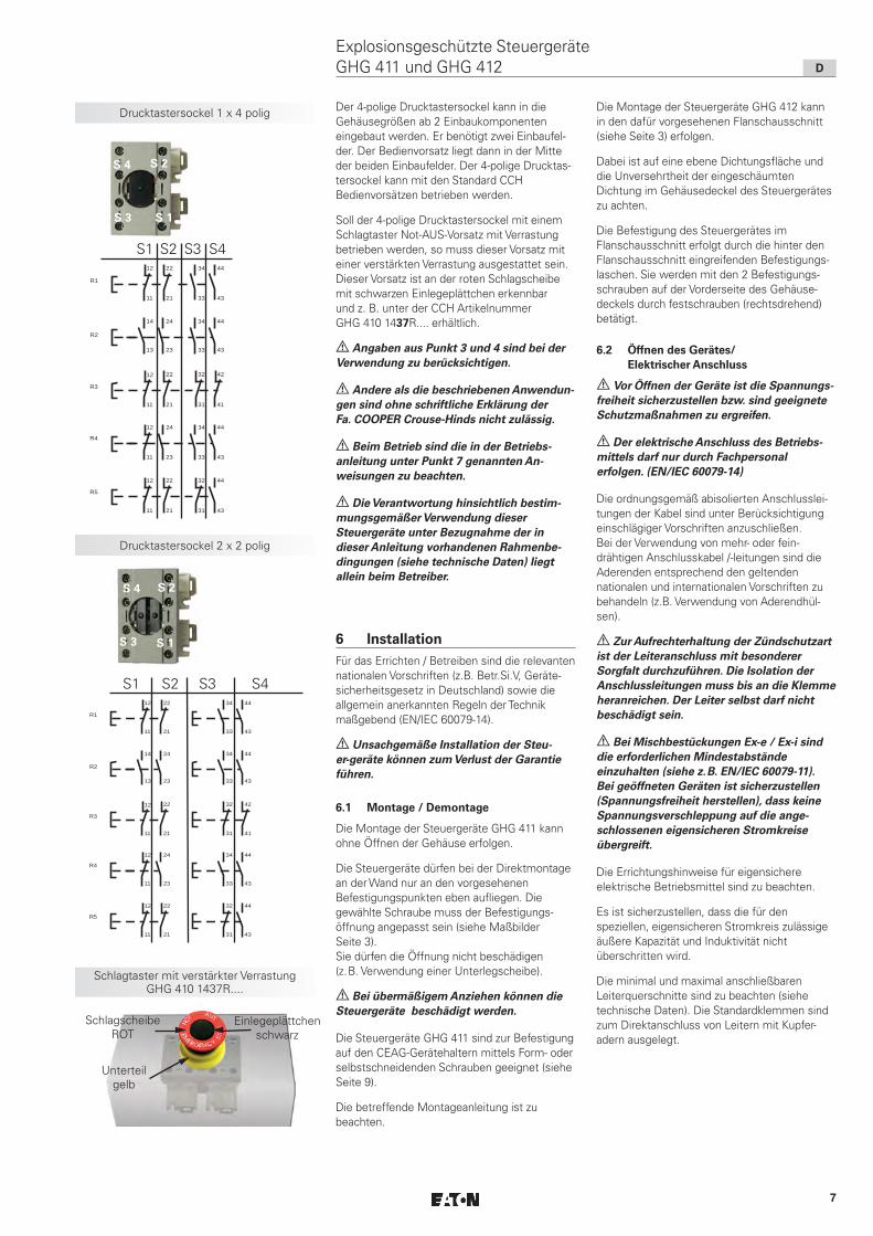
Der 4-polige Drucktastersockel kann in die Gehäusegrößen ab 2 Einbaukomponenten eingebaut werden. Er benötigt zwei Einbaufel-der. Der Bedienvorsatz liegt dann in der Mitte der beiden Einbaufelder. Der 4-polige Drucktas-tersockel kann mit den Standard CCH Bedien vorsätzen betrieben werden.
Soll der 4-polige Drucktastersockel mit einem Schlagtaster Not-AUS-Vorsatz mit Verrastung betrieben werden, so muss dieser Vorsatz mit einer verstärkten Verrastung ausgestattet sein. Dieser Vorsatz ist an der roten Schlagscheibe mit schwarzen Einlegeplättchen erkennbar und z. B. unter der CCH Artikelnummer GHG 410 1437R.... erhältlich.
a Angaben aus Punkt 3 und 4 sind bei der Verwendung zu berücksichtigen.
a Andere als die beschriebenen Anwendun-gen sind ohne schriftliche Erklärung der Fa. COOPER Crouse-Hinds nicht zulässig.
a Beim Betrieb sind die in der Betriebs- anleitung unter Punkt 7 genannten An- weisungen zu beachten.
a Die Verantwortung hinsichtlich bestim-mungsgemäßer Verwendung dieser Steuergeräte unter Bezugnahme der in dieser Anleitung vorhandenen Rahmenbe-dingungen (siehe technische Daten) liegt allein beim Betreiber.
6 InstallationFür das Errichten / Betreiben sind die relevanten nationalen Vorschriften (z.B. Betr.Si.V, Geräte-sicherheitsgesetz in Deutschland) sowie die allgemein anerkannten Regeln der Technik maßgebend (EN/IEC 60079-14).
a Unsachgemäße Installation der Steu-er-geräte können zum Verlust der Garantie führen.
6.1 Montage / Demontage
Die Montage der Steuergeräte GHG 411 kann ohne Öffnen der Gehäuse erfolgen.
Die Steuergeräte dürfen bei der Direktmontage an der Wand nur an den vorgesehenen Befestigungspunkten eben aufliegen. Die gewählte Schraube muss der Befestigungs-öffnung angepasst sein (siehe Maßbilder Seite 3). Sie dürfen die Öffnung nicht beschädigen (z.B. Verwendung einer Unterlegscheibe).
a Bei übermäßigem Anziehen können die Steuergeräte beschädigt werden.
Die Steuergeräte GHG 411 sind zur Befestigung auf den CEAG-Gerätehaltern mittels Form- oder selbstschneidenden Schrauben geeignet (siehe Seite 9).
Die betreffende Montageanleitung ist zu beachten.
Die Montage der Steuergeräte GHG 412 kann in den dafür vorgesehenen Flanschausschnitt (siehe Seite 3) erfolgen.
Dabei ist auf eine ebene Dichtungsfläche und die Unversehrtheit der eingeschäumten Dichtung im Gehäusedeckel des Steuergerätes zu achten.
Die Befestigung des Steuergerätes im Flanschausschnitt erfolgt durch die hinter den Flanschausschnitt eingreifenden Befestigungs-laschen. Sie werden mit den 2 Befestigungs-schrauben auf der Vorderseite des Gehäuse-deckels durch festschrauben (rechtsdrehend) betätigt.
6.2 Öffnen des Gerätes/ Elektrischer Anschluss
a Vor Öffnen der Geräte ist die Spannungs-freiheit sicherzustellen bzw. sind geeignete Schutzmaßnahmen zu ergreifen.
a Der elektrische Anschluss des Betriebs-mittels darf nur durch Fachpersonal erfolgen. (EN/IEC 60079-14)
Die ordnungsgemäß abisolierten Anschlusslei-tungen der Kabel sind unter Berücksichtigung einschlägiger Vorschriften anzuschließen. Bei der Verwendung von mehr- oder fein-drähtigen Anschlusskabel /-leitungen sind die Aderenden entsprechend den geltenden nationalen und internationalen Vorschriften zu behandeln (z.B. Verwendung von Aderendhül-sen).
a Zur Aufrechterhaltung der Zündschutzart ist der Leiteranschluss mit besonderer Sorgfalt durchzuführen. Die Isolation der Anschlussleitungen muss bis an die Klemme heranreichen. Der Leiter selbst darf nicht beschädigt sein.
a Bei Mischbestückungen Ex-e / Ex-i sind die erforderlichen Mindestabstände einzuhalten (siehe z.B. EN/IEC 60079-11). Bei geöffneten Geräten ist sicherzustellen (Spannungsfreiheit herstellen), dass keine Spannungsverschleppung auf die ange-schlossenen eigensicheren Stromkreise übergreift.
Die Errichtungshinweise für eigensichere elektrische Betriebsmittel sind zu beachten.
Es ist sicherzustellen, dass die für den speziellen, eigensicheren Stromkreis zulässige äußere Kapazität und Induktivität nicht überschritten wird.
Die minimal und maximal anschließbaren Leiterquerschnitte sind zu beachten (siehe technische Daten). Die Standardklemmen sind zum Direktanschluss von Leitern mit Kupfer-adern ausgelegt.
Drucktastersockel 1 x 4 polig
Drucktastersockel 2 x 2 polig
Schlagtaster mit verstärkter Verrastung GHG 410 1437R....
21
22 44
43
R1
34
3311
12
44
43
R2
34
33
24
23
14
13
21
22
R3
11
12
41
42
31
32
44
43
R4
34
33
24
2311
12
21
22
R5
11
12
31
32 44
43
S 1
S 2S 4
S 3
S 2S 4
S 3
S4
S 1
21
22 44
43
R1
34
3311
12
44
43
R2
34
33
24
23
14
13
21
22
R3
11
12
41
42
31
32
44
43
R4
34
33
24
2311
12
21
22
R5
11
12
31
32 44
43
S2 S3S1
Schlagscheibe ROT
Einlegeplättchen schwarz
Unterteil gelb
S4S2 S3S1
D
Explosionsgeschützte Steuergeräte GHG 411 und GHG 412

8
Schaltabwicklungen
D
Explosionsgeschützte Steuergeräte GHG 411 und GHG 412
Alle Schrauben und/oder Muttern der An schlussklemmen, auch die der nicht benutzten, sind fest anzuziehen.
! Wird das Betriebsmittel in der Ausführung „Schutzisoliert“ ausgeführt, kann das entsprechende Klebeschild ( ) GHG 905 1002 P0005 beim Hersteller angefordert werden.
! Wird die eingebaute Klemmentragschiene nicht komplett mit Reihenklemmen bestückt, muss die Klemmentragschiene in den Potentialausgleich mit einbezogen werden.
Das Schaltbild der Einbaukomponenten ist auf den Komponenten angegeben, dem Schaltgerät beigelegt oder aus der Betriebsanleitung zu entnehmen.
Werden die Einbaukomponenten (Messinstru-ment AM/VM72 und AM/VM45, Drucktaster- sockel, Signalleuchtensockel, Steuerschalterso-ckel, Potentiometersockel usw.) zur leichteren Verdrahtung aus der Profilschiene im Gehäuse-boden der Steuergeräte ausgeschnappt, sind die Komponenten hiernach wieder vorschrifts-mäßig in die entsprechende Einrastposition auf der Profilschiene einzusetzen. Zum Ausschnap-pen der Komponenten (u.a. auch die Messinstru mente AM/VM72 + AM/VM45), werden die Rasthaken zum entriegeln nach außen gezogen.
Um ein korrektes Schließen der Geräte zu gewährleisten, ist ein Schalten an der Schalt-achse der Schalteinsätze bei geöffnetem Gerät nicht zulässig.
a Die Einrastpositionen der Ein- baukomponenten müssen mit den Einker-bungen der Profilschiene übereinstimmen!
6.3 Kabel- und Leitungs- einführungen (KLE); Verschlussstopfen
a Es dürfen generell nur bescheinigte und geeignete KLE's und Verschlussstopfen verwendet werden. Für bewegliche Leitungen sind Trompeten verschraubungen oder andere geeignete Einführungen mit zusätzlicher Zugentlastung zu verwenden.
Die für die eingesetzten KLE maßgebenden Montagerichtlinien sind zu beachten. Beim Einsatz von KLE mit einer niedrigeren als der für das Gerät zutreffenden IP-Schutzart, wird die IP-Schutzart des gesamten Gerätes reduziert.
Eigensichere Stromkreise sind über die farblich (hellblau) gekennzeichneten KLE einzuführen. Beim Einsatz von nur für fest verlegte Leitungen geeigneten Kabel- und Leitungsein-führungen ist sicherzustellen, dass keine unzulässig hohe mechanische Beanspruchung der Kabel- und Leitungseinführung und/oder deren Dichtung erfolgt.
Nicht benutzte Einführungsöffnungen sind mit einem bescheinigten Verschlussstopfen zu verschließen, um die Mindestschutzart herzustellen.
Es ist darauf zu achten, dass bei der Installation der KLE’s die für den Leitungsdurchmesser geeigneten Dichtungseinsätze verwendet werden. Bei ausschneidbaren Dichtungs-einsätzen ist sicherzustellen, dass der Einsatz ordnungsgemäß dem Leitungsdurchmesser angepasst wird. Zur Sicherstellung der erforderlichen Mindestschutzart sind die KLE’s fest anzuziehen.
a Bei übermäßigem Anziehen kann die Schutzart beeinträchtigt werden.
a Beim Anziehen der Hutmutter der Metall-KLE (z.B. Typ ADE) ist die Verschrau-bung mit einem geeigneten Werkzeug gegen Verdrehen zu sichern.
Alle nicht benutzten metrischen CEAG KLE sind mit dem bescheinigten Verschluss für metrische KLE zu verschließen.
6.4 Flansche und Metallplatten *
Müssen Flanschplatten demontiert werden (z.B. zum Bohren von Einführungsöffnungen), ist bei der Montage zur Aufrechterhaltung der Mindestschutzart auf den korrekten Sitz der Flanschplatte zu achten.
a Von außen herangeführte PE-Leitungen sind auf die dafür vorgesehene PE-Klemme am Flansch anzuschließen. Der maximale Anschlussquerschnitt beträgt 6 mm².
a Metallflansche, Metallplatten und Metallverschraubungen müssen in den Potentialausgleich miteinbezogen werden.
* z.Zt. nicht bescheinigt für Kategorie II D
6.5 Schließen des Gerätes / Deckelverschluss
a Beim Aufsetzen der Gehäusedeckel ist darauf zu achten, dass die Vorsätze korrekt mit den Einbaukomponenten übereinstim-men, dass die Schaltachse der Schalteinsät-ze korrekt in die Mitnehmeröffnung der Schaltgriffe eingeführt wird, und der zum Gehäuse unterteil gehörige Deckel ver- wendet wird.
Der Schaltgriff muss in der gleichen Stellung stehen, die er beim Öffnen des Gerätes innehatte.
Alle Fremdkörper sind aus dem Gerät zu entfernen.
Zur Sicherstellung der erforderlichen Mindest-schutzart sind die Deckelschrauben fest anzuziehen.
Bei übermäßigem Anziehen kann die Schutzart beeinträchtigt werden.
Drucktaster
Doppeldrucktaster
Schlagtastertaster
Schlagtastertaster mit Schlüssel
Schlüsseltaster
Potentiometer
Steuerschalter R6201
Steuerschalter R6102
Steuerschalter R6002
Steuerschalter R5307
Steuerschalter R5507
Steuerschalter R8701

9
Befestigungslöcher auf Gerätehalter Größe 1
Befestigungslöcher auf Gerätehalter Größe 2
D
Explosionsgeschützte Steuergeräte GHG 411 und GHG 412
8 Reparatur / Instandsetzung / ÄnderungInstandsetzungsarbeiten / Reparaturen dürfen nur mit CEAG Originalersatzteilen vorgenom-men werden.
a Bei Schäden an der druckfesten Kapse-lung ist nur ein Austausch zulässig. Im Zweifels falle ist das betroffene Betriebsmit-tel an CEAG zur Reparatur zurückzugeben.
a Reparaturen, die den Explosionsschutz betreffen, dürfen nur von COOPER Crouse-Hinds oder einer qualifizierten Elektrofach-kraft in Übereinstimmung mit national geltenden Regeln durchgeführt werden. (EN/IEC 60079-19)
Umbauten oder Änderungen am Betriebsmittel sind nicht gestattet; ausgenommen ist das Anbringen von zusätzlichen KLE’s im Rahmen der Zulassung des Betriebsmittels oder nach Angaben des Herstellers.
Bei Austausch einzelner Einbaukomponenten (Messinstrument, Taster usw.) ist Pkt. 6.2 „Öffnen des Gerätes / Elektrischer Anschluss“ zu beachten.
9 Entsorgung / WiederverwertungBei der Entsorgung des Betriebsmittels und der Einbaukomponenten (Messinstrument, Signalleuchte, Taster usw.) sind die jeweils geltenden nationalen Abfallbeseitigungsvor-schriften zu beachten.
Zur Erleichterung der Wiederverwertbarkeit von Einzelteilen sind Kunststoffteile mit dem Kennzeichen des verwendeten Kunststoffes versehen.
Programmänderungen und -ergänzungen sind vorbehalten.
6.6 Inbetriebnahme
Vor Inbetriebnahme des Betriebsmittels sind die in den einzelnen nationalen Bestimmungen genannten Prüfungen durchzuführen.
Außerdem ist vor der Inbetriebnahme die korrekte Funktion und Installation des Betriebs-mittels und der Einbaukomponenten (Messinst-rument, Signalleuchte, Taster usw.) in Überein-stimmung mit dieser Betriebsanleitung und anderen anwendbaren Bestimmungen zu überprüfen.
Die Nullpunkteinstellung des Messinstrumente-zeigers ist vor der Inbetriebnahme zu über-prü-fen. Gegebenenfalls mit der Justierschraube den Messgerätezeiger auf den Nullpunkt einjustieren.
Die Gasgruppe (II B bzw. II C) des eigensiche-ren Stromkreises ist zur Bewertung der Gasgruppe der Einbaukomponenten zu berücksichtigen.
a Unsachgemäßer Betrieb der Steuergeräte kann zum Verlust der Garantie führen.
7 Instandhaltung / Wartunga Die für die Wartung / Instandhaltung von elektrischen Betriebsmitteln in explosions-gefährdeten Bereichen geltenden nationalen Bestimmungen sind einzuhalten (z.B. EN/IEC 60079-17).
Vor Öffnen des Gehäuses Spannungsfreiheit sicherstellen bzw. geeignete Schutzmaßnah-men ergreifen.
Bei eigensicheren Stromkreisen ist das Arbeiten unter Spannung zulässig.
Die erforderlichen Wartungsintervalle sind anwendungsspezifisch und daher in Abhängig-keit von den Einsatzbedingungen vom Betreiber festzulegen.
Im Rahmen der Wartung sind vor allem die Teile, von denen die Zündschutzart abhängt, zu prüfen (z.B. Unversehrtheit der druckfesten Komponenten, des Gehäuses, der Dichtungen und der Kabel- und Leitungseinführungen), sowie die Schaltwerksfunktion.
Sollte bei einer Wartung festgestellt werden, dass Instandsetzungsarbeiten erforderlich sind, ist Abschnitt 8 dieser Betriebsanleitung zu beachten.
Gerätehalter für Gitterrinnen- und Wand befestigung
Gerätehalter für Gitterrinnen- und Wand befestigung
Befestigungs-löcher für Steuergerät GHG 411 81
Gerätehalter für Rohrbefestigung
Gerätehalter für Rohrbefesti-gung
Befestigungslöcher für Steuergerät GHG 411 82
Befestigungslöcher für Steuergerät
GHG 411 83

10
E
Explosion-protected control units GHG 411 and 412
Dimensions in mm
X = fixing dimensions
1 Technical data
1.1 Control unit assemblies
ATEX type examination certificate: PTB 00 ATEX 3117Marking acc. to 2014/34/EU and standard:
EN 60079-0 D II 2 G Ex e mb IIC T6 GbD II 2 G Ex e ib mb IIC T6 GbD II 2 G Ex d e mb IIC T6 GbD II 2 G Ex d e ib mb IIC T6 GbD II 2 D Ex tb IIIC T80 °C Db
IECEx type examination certificate: IECEx BKI 04.0003Category of application:
IEC60079-0 Ex e IIC T6Ex e ib IIC T6Ex d e IIC T6Ex d e ib IIC T6
Rated voltage: up to max. 690 V Rated current: max. 16 APermissible ambient temperature: Other temperatures possible for special versions.
-20° C to +40° C (standard version)
Perm. storage temperature in original packing: -20° C to +40° C Degree of protection to IEC/EN 60529: IP 66 (standard version)
IP 65 Double push buttonInsulation class acc. to IEC/EN 61140: I - with metal flange
II - plastic terminal boxes fulfil this requirementPE- terminal: 2 x 4 mm²Terminals: see built-in componentsCable entries (standard version): 1 x M25suitable cables and test torques of the pressure srewCabel entry: M12 M16 M20 M25 M32seel 1+2+3 (Ø mm / Nm) 1 2 3 min.
max. (1) (2) --- --- 5,5 / 1,5 7,0 / 1,0
8,0 / 1,5 10,0 / 2,0 ---
seel 1+2 (Ø mm / Nm) 1 2 3 min.
max. (1) (2) --- 5,5 / 1,0 7,0 / 1,0
7,0 / 1,5 9,0 / 1,4
10,0 / 2,3 13,0 / 2,6
14,0 / 3,0 17,0 / 4,0
seel 1 (Ø mm / Nm) 1 2 3 min.
max. (2)5,0 / 0,8 7,0 / 1,0
7,0 / 1,0 10,0 / 1,4
9,5 / 1,0 13,0 / 1,7
13,5 / 1,3 17,5 /2,3
17,5 / 1,5 21,0 / 1,3
Test torque for screw in thread cable entry (Nm) 1.2 3.3 2.7 3.0 5.0(1) The tests of clamping ranges and torque values were performed with metal mandrel. The clamping range can
vary by using cables with different manufacturing tolerances and material properties. Please use the combination of sealing 1 + 2 + 3 for the intermediate region.
(2) When selecting the seal rubber, ensure that the cap nut can be tightened when carrying out any future maintenance work on the cable entry.
Weight:Control unit GHG 411 81 (P411) approx. 0.25 kg (empty weight)Control unit GHG 411 82 (P412) approx. 0.35 kg (empty weight)Control unit GHG 411 83 (P413) approx. 0.45 kg (empty weight)Control unit GHG 412 82 (F412) approx. 0.80 kg (incl. measuring instrument)Test torques: Cover screws 2.50 Nm
GHG 411 81
GHG 411 82
GHG 411 83
GHG 412 82
Flange opening for GHG 412 82
1.2 Actuator general
ATEX type examination certificate: IBExU14ATEX1030U
Marking acc. to 2014/34/EU and standard:
EN 60079-0 D II 2 G Ex d e IIC/IIB Gb
D I M 2 Ex d e I Mb
IECEx type examination certificate: IECEx IBE 14.0005U
Category of application:
IEC60079-0 Ex d e IIC/IIB Gb
Ex d e I Mb
Operating temperature:
II 2 G ... IIC -45 °C to +80 °C
II 2 G ... IIB -60 °C to +80 °C

11
E
Explosion-protected control units GHG 411 and 412
Dimensions of actuator elements
Pushbutton actuator
Double pushbutton actuator
Mushroom-head pushbutton actuator
Signal lamp bezel with lens
Mushroom-head pushbutton actuator "EMERGENCY STOP"
Mushroom-head pushbutton actuator "EMERGENCY STOP"
with key release
Key-operated switch* -/-pushbutton actuator
* not yet certified for category II D
Rated voltage: up to 500 V
Rated currentRated supply terminal
Permissible ambient temperature max.
14 A 2.5 mm² 40 °C
16 A 4.0 mm² single wire 40 °C
12 A 2.5 mm² 50 °C
15 A 4.0 mm² single wire 50 °C
Switching capacity acc. to AC 15
(EN 60947-5-1): 250 V / 6 A 500 V / 4.0 A
Switching capacity acc. to DC 13
(EN 60947-5-1): 24 V / 6 A 60 V / 0.8 A 110 V / 0.5 A
with gold-tipped contacts: max. 400 mA
Supply terminal: 2 x 1.0 - 2.5 mm²
1 x 4.0 mm² single wire
Test torques: 2.5 Nm
Weight: 2 pole approx 0.15 kg
4 pole approx 0.35 kg
1.2.1 Actuator 2 pole for push button, Mushroom head p.b., switch and Key-operated pushbutton
1.2.2 Actuator 4 pole for push button, Mushroom head p.b., switch and Key-operated pushbutton
12.3 Potentiometer
Rated voltage: up to 250 VRating: 1 WTurning range: 270°Scale: 0 - 100%Supply terminal/Test torques: 2 x 1.0 - 2.5 mm²
1 x 4.0 mm² single wireTest torques: 2.5 NmWeight: approx. 0.15 kg
1.3 Signallamp
ATEX type examination certificate: IBExU 12ATEX 1047 UMarking acc. to 2014/34/EU and standard:
EN 60079-0 D II 2 G Ex de IIC/IIB GbD II 2 G Ex d ia IIC/IIB Gb
IECEX type examination certificate: IECEx IBE 13.0031UCategory of application:
IEC60079-0 Ex d e IIC/IIB GbEx d ia IIC/IIB Gb
Appliation temperatureD II 2 G Ex ... IIC -45 °C up to +60 °CD II 2 G Ex ... IIB -60 °C up to +60 °C
(Other temperatures possible with special versions)Rated voltage /Rated current:
"e" increased safety 20 V up to 254 V AC/DC 4 up to 15 mA"i" intrinsically safe version 10 V up to 30 V DC max. 25 mA"e" increased safety 12 V up to 24 V AC/DC max. 24 mA
Ex-i Datas: U i 30 VI i 100 mACi 0Li 0Pi 750 mW
Supply terminal: 2 x 1.0 - 2.5 mm²; 1 x 4.0 mm² single wireTest torques: 2.5 NmWeight: approx. 0.15 kg

12
Dimension for actuator elements
2
1
Glass for measuring instrument AM/VM45
Glass for measuring instrument AM/VM72
Switch- and potentiometer actuator
X = fixing dimensions
Fig. 1
E
Explosion-protected control units GHG 411 and 412
1.5 Terminal block
1.4 AM45 / AM72 measuring Instrument VM45 / VM72 measuring instrument:
ATEX type examination certificate: BVS 14 ATEX E 125
Marking acc. to 2014/34/EU and standard:
Moving iron D II 2 G Ex e IIC Gb
D II 2 G Ex e mb II CGb
Moving coil D II 2 G Ex ib IIC Gb
IECEx type examination certificate: IECEx BVS 14.0082U
Category of application:
Moving iron Ex e IIC Gb
Ex e mb IIC Gb
Moving coil Ex ib IIC Gb
Operating temperature -55 °C to +80 °C
Rated voltage: to max. 500 V
Moving iron Moving coil
Measuring accuracy: Klasse 2,5 Klasse 1,5
Overload range: fold at sec. fold at sec
fold at sec.
fold at sec
indicated
Measuring range:
direct
Power consumption:
Coil: turns
Internal resistance:
Li:
Ci:
Ui:
I i :
Supply terminals: fine- / multy wire
solid wire
Test torques:
Weight: AM/VM 45
AM/VM 72
EN 60079-0
IEC 60079-0
10 - - 25 10 - - 5
25 - - 4
50 - - 1
1:1,5
AM: n / 1A 0 - 24 mA
0 - 25 A 4 - 24 mA
VM45: 6 - 415V
VM72: 6 - 660V
VM45: 0.91 - 1.76VA
VM72: 0.91 - 2.65VA
26.5
2.5 Ohm +- 30%
- max. 0.1 mH
- max. 0.1 nF
- max. 30 V
- max. 150 mA
2 x 0.5 - 2.5 mm²
1 x 4.0 mm²
2.5 Nm
approx. 0.35 Kg
approx. 0.40 Kg
1.6 Intrinsically safe circuits:Intrinsically safe circuits: Max. safe voltage Um: 690 Veff
Safe galvanic isolation from all other circuits and earth
ATEX certificate: SEV 13 ATEX 0178 U
Marking acc. to 2014/34/EU and standard:
EN 60079-0 II 2 G Ex eb IIC
IECEx certificate: IECEx SEV 13.0012 U
Category of application: IEC60079-0 Ex eb IIC
Type of terminal: 6 x MUT 4
Rated voltage: up to 352 V
Conductor cross-section: 2 x 0.2 - 4.0 mm²
Test torques: 0.6 - 0.8 Nm
Weight: approx. 0.08 kg

13
2 Safety instructions
aTarget group: For skilled electricians and qualified personnel in accordance with
national legislation, including the relevant standards and, where applicable, in acc. with IEC/EN 60079-14 on electrical appara-tus for explosive atmospheres.
The control units GHG 411 and GHG 412 are not suitable for zone 0 and Zone 20 hazard-ous areas.
The temperature class and type of protec-tion stated on the apparatus shall be observed.
Modifications or changes to the control units are not permitted. They shall be used for their intended purpose and shall be in a perfect and clean state.
The requirements of the IEC/EN 60079-31 regarding excessive dust deposits and temperature to be considered from the user.
Only original CEAG parts may be used as replacements and for repairs. Repairs that affect the explosion protection may only be carried out by COOPER Crouse-Hinds or by a qualified electrician in compliance with the respective national regulations.
Prior to being put into operation, the control units shall be checked in accordance with the instructions as per section 6.
The national safety rules and regulations for the prevention of accidents, as well as the safety instructions included in these operating instructions, that, like this text, are set in italics, shall be observed!!
3 Conformity with standardsThe apparatus is conform to the standards specified in the EC-Declaration of conformity, enclosed separately.
References to standards and directives in these operating instructions always relate to the latest version. Other additions (e.g. details relating to the year) shall be observed.
4 Field of applicationThe control units are intended for use in potentially explosive atmospheres in zones 1, 2 as well as in Zones 21 and 22 in accordance with IEC/EN 60079-10-1 and IEC/EN 60079-10-2.
The enclosure materials used, including any external metal parts, are high quality materials that ensure a corrosion resistance and resistance to chemical substances according to the requirements for use in a ”normal industrial atmosphere”
- impact resistant polyamide - special steel AISI 316 L.
In case of use in an extremely aggressive atmosphere, please refer to manufacturer.
5 Application / PropertiesThe control units GHG 411 and 412 are intended for the local control of electrical installations in potentially explosive atmos-pheres. The units are fitted with built-in components according to the respective application.
Specially marked special versions of the control units can be used in ”intrinsically safe circuits”.
The electrical limiting values that are decisive for the intrinsic safety shall be observed.
The version with gold-tipped contacts is suited for switching extra-low voltage circuits. Special attention shall be paid to the maximum current load (see technical data). The contact chamber of the gold-tipped version is marked with the letter ”G” or colour-coded.
To ensure a safe and reliable disconnection, the normally closed contacts are designed as compulsory opening contacts.
Where required, the bases are fitted with 0.6 W resistors, fine-wire fuses and diodes (max. power dissipation 1 W).
The measuring instruments AM/VM72 and AM/VM45 are used for the local indication of electrical values. See ”Technical Data” for details of measuring mechanism, accuracy and connection.
With measuring instruments AM/VM72 and AM/VM45 for c.t. connection n/1A (Fig. 1, item 2) the interchangeable scales can be exchanged via a flap on the upper part of the measuring instrument (Fig. 1, item 1).
When the switch collar of small control switches is cut out at the respective locking position, they can be padlocked (padlock shackle Ø up to 5 mm).
E
Explosion-protected control units GHG 411 and 412

14
The 4 pole pushbutton contact can be added with the standard CCH actuators.
If the 4 pole pushbutton contact is added with an Emergency STOP Mushroom-head pushbutton actuator, then you have to use the actuators with CCH order number GHG 410 1437R. This actuators can be recognized by the red thrust washer and black inserting sign.
a The data according to sections 3 and 4 shall be taken into account during use.
a Applications other than those described are not permissible without a written declaration of consent from Messrs. COOPER Crouse-Hinds.
a During operation the instructions stated in section 7 of the operating instructions shall be observed.
a The sole responsibility with respect to the suitability and proper use of the control switches with regard to the basic require-ments of these instructions (see technical data) lies with the operator.
6 InstallationThe relevant national regulations (e.g. Betr.Si.V, the equipment safety law for Germany) and the generally recognized rules of engineering apply for the installation and operation IEC/EN 60079-14.
a The improper installation and operation of control switches may result in the invalidation of the guarantee.
6.1 Mounting
The control units GHG 411 can be mounted without opening the enclosure.
When the control units are mounted directly onto the wall, they shall rest evenly only on the fastening points provided for this purpose.
The screw chosen shall fit the fixing hole (see dimensional drawings, page 10) and shall not damage the hole (e.g. use of a washer).
The apparatus shall be fixed diagonally with a minimum of 2 screws.
a If the screws are overtightened, the apparatus may be damaged.
The control units GHG 411 and GHG 412 are suited for mounting on CEAG apparatus holders by means of self-cutting screws (see pages 16).
See the respective mounting instructions.
The control units GHG 412 can be mounted in the flange openings provided for this purpose (see page 10).
Here special attention shall be paid to an even sealing surface and the perfect condition of the seal that is foamed into the enclosure cover of the control unit.
The control unit is mounted in the flange opening by means of fixing lugs that engage behind the flange opening.
These are actuated by turning the 2 fixing screws on the front of the enclosure cover clockwise.
6.2 Opening apparatus/ Electrical connection
a Before opening the apparatus, it is necessary to ensure that there is no voltage or to take suitable protective measures.
a The electrical connection of the may only be carried out by specialists. (IEC/EN 60079-14)
The properly bared conductors of cables shall be connected with due regard to the respective regulations. If multi- or fine-wire connection cables are used, the wire ends shall be handled according to the applicable national and international regulations (e.g. use of multicore cable ends).
a To maintain the explosion protection, conductors shall be connected with special care.The insulation shall reach up to the terminal. The conductor itself shall not be damaged.
a In the case of mixed Ex-e / Ex-i installa-tions, the required minimum clearances shall be maintained (see, for example, IEC/EN 60079-11).When apparatus is open, it is necessary to ensure (disconnect voltage supply) that no voltage is carried over into the connected intrinsically safe circuits.
The installation instructions for intrinsically safe electrical apparatus shall be observed.
It is necessary to ensure that the permissible external capacitance and inductance of the special intrinsically safe circuits are not exceeded.
The minimum and maximum conductor cross sections that can be connected shall be observed (see technical data).
Actuator 1 x 4 pole
Actuator 2 x 2 pole
Mushroom-head pushbutton actuator "EMERGENCY STOP" GHG 410 1437R....
21
22 44
43
R1
34
3311
12
44
43
R2
34
33
24
23
14
13
21
22
R3
11
12
41
42
31
32
44
43
R4
34
33
24
2311
12
21
22
R5
11
12
31
32 44
43
S 1
S 2S 4
S 3
S 2S 4
S 3
S4
S 1
21
22 44
43
R1
34
3311
12
44
43
R2
34
33
24
23
14
13
21
22
R3
11
12
41
42
31
32
44
43
R4
34
33
24
2311
12
21
22
R5
11
12
31
32 44
43
S2 S3S1
thrust washer red
inserting sign black
base yellow
S4S2 S3S1
E
Explosion-protected control units GHG 411 and 412
15
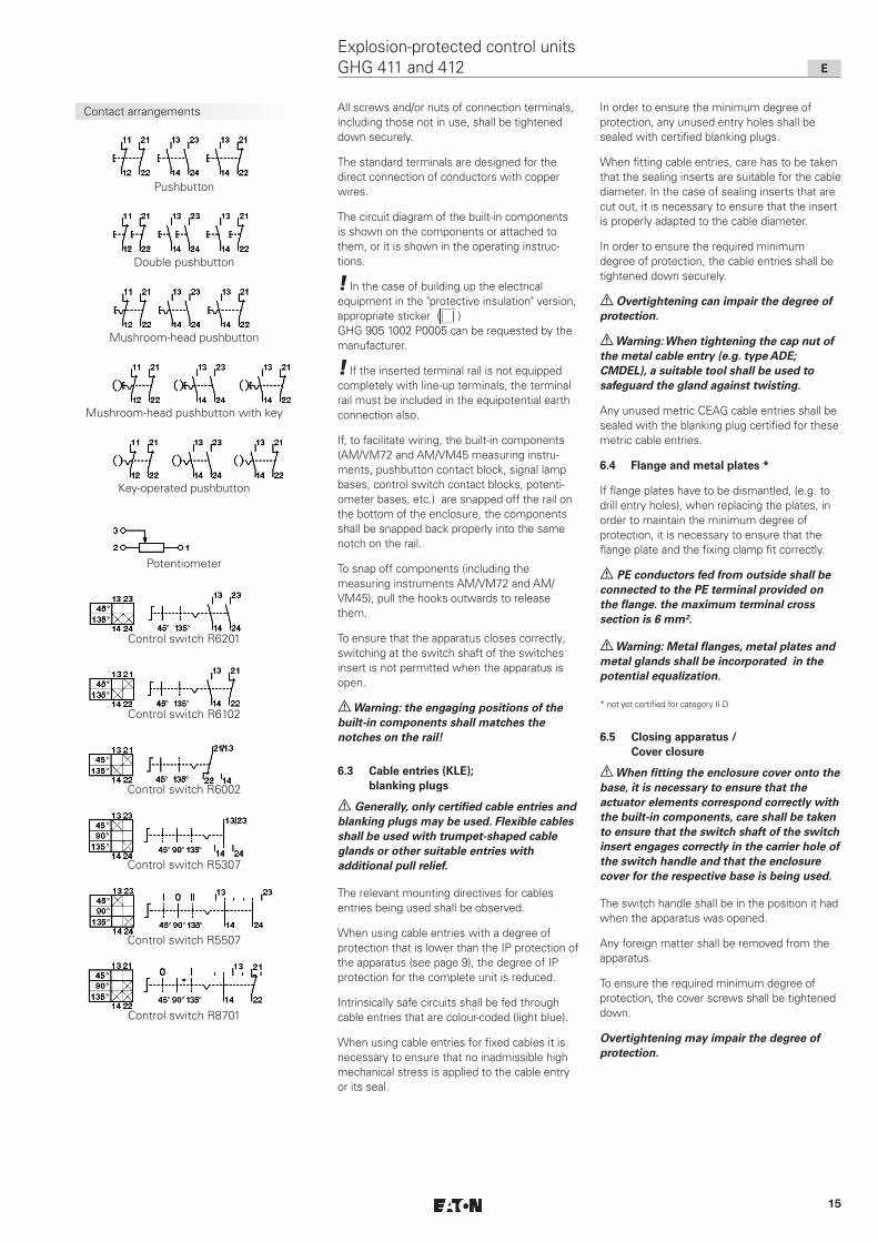
Contact arrangements All screws and/or nuts of connection terminals, including those not in use, shall be tightened down securely.
The standard terminals are designed for the direct connection of conductors with copper wires.
The circuit diagram of the built-in components is shown on the components or attached to them, or it is shown in the operating instruc-tions.
! In the case of building up the electrical equipment in the "protective insulation" version, appropriate sticker ( ) GHG 905 1002 P0005 can be requested by the manufacturer.
! If the inserted terminal rail is not equipped completely with line-up terminals, the terminal rail must be included in the equipotential earth connection also.
If, to facilitate wiring, the built-in components (AM/VM72 and AM/VM45 measuring instru-ments, pushbutton contact block, signal lamp bases, control switch contact blocks, potenti-ometer bases, etc.) are snapped off the rail on the bottom of the enclosure, the components shall be snapped back properly into the same notch on the rail.
To snap off components (including the measuring instruments AM/VM72 and AM/VM45), pull the hooks outwards to release them.
To ensure that the apparatus closes correctly, switching at the switch shaft of the switches insert is not permitted when the apparatus is open.
a Warning: the engaging positions of the built-in components shall matches the notches on the rail!
6.3 Cable entries (KLE); blanking plugs
a Generally, only certified cable entries and blanking plugs may be used. Flexible cables shall be used with trumpet-shaped cable glands or other suitable entries with additional pull relief.
The relevant mounting directives for cables entries being used shall be observed.
When using cable entries with a degree of protection that is lower than the IP protection of the apparatus (see page 9), the degree of IP protection for the complete unit is reduced.
Intrinsically safe circuits shall be fed through cable entries that are colour-coded (light blue).
When using cable entries for fixed cables it is necessary to ensure that no inadmissible high mechanical stress is applied to the cable entry or its seal.
In order to ensure the minimum degree of protection, any unused entry holes shall be sealed with certified blanking plugs.
When fitting cable entries, care has to be taken that the sealing inserts are suitable for the cable diameter. In the case of sealing inserts that are cut out, it is necessary to ensure that the insert is properly adapted to the cable diameter.
In order to ensure the required minimum degree of protection, the cable entries shall be tightened down securely.
a Overtightening can impair the degree of protection.
a Warning: When tightening the cap nut of the metal cable entry (e.g. type ADE; CMDEL), a suitable tool shall be used to safeguard the gland against twisting.
Any unused metric CEAG cable entries shall be sealed with the blanking plug certified for these metric cable entries.
6.4 Flange and metal plates *
If flange plates have to be dismantled, (e.g. to drill entry holes), when replacing the plates, in order to maintain the minimum degree of protection, it is necessary to ensure that the flange plate and the fixing clamp fit correctly.
a PE conductors fed from outside shall be connected to the PE terminal provided on the flange. the maximum terminal cross section is 6 mm².
a Warning: Metal flanges, metal plates and metal glands shall be incorporated in the potential equalization.
* not yet certified for category II D
6.5 Closing apparatus / Cover closure
a When fitting the enclosure cover onto the base, it is necessary to ensure that the actuator elements correspond correctly with the built-in components, care shall be taken to ensure that the switch shaft of the switch insert engages correctly in the carrier hole of the switch handle and that the enclosure cover for the respective base is being used.
The switch handle shall be in the position it had when the apparatus was opened.
Any foreign matter shall be removed from the apparatus.
To ensure the required minimum degree of protection, the cover screws shall be tightened down.
Overtightening may impair the degree of protection.
Pushbutton
Double pushbutton
Mushroom-head pushbutton
Mushroom-head pushbutton with key
Key-operated pushbutton
Potentiometer
Control switch R6201
Control switch R6102
Control switch R6002
Control switch R5307
Control switch R5507
Control switch R8701
E
Explosion-protected control units GHG 411 and 412

16
Fastening holes of the apparatus mounting plates size 1
Fastening holes of the apparatus mounting plates size 2
8 Repairs / Overhaul / ModificationOnly original CEAG parts shall be used for carrying out repairs.
a In the event of damage to the flameproof encapsulation, replacement of these components is mandatory. In case of doubt, the respective apparatus shall be sent to COOPER Crouse-Hinds for repair.
a Repairs that affect the explosion protection may only be carried out by COOPER Crouse-Hinds or by a qualified electrician in compliance with the respective national regulations (IEC/EN 60079-19).
Apparatus modifications or design changes are not permitted; excepted from this is the fitting of additional cable entries within the scope of the apparatus approvals or acc. to the instruc-tions given by the manufacturer.
When replacing individual built-in components (pushbuttons, etc.) section 6.2 ”Opening apparatus / Electrical connection” shall be observed.
9 Disposal / RecyclingThe respective valid national regulations for waste disposal shall be observed when disposing of apparatus.
To facilitate the recycling of individual parts, parts made of moulded plastic shall bear the marking for the type of plastic used.
The product range is subject to changes and additions.
6.6 Putting into operation
Before putting the apparatus into operation, the tests specified in the individual national regulations shall be performed.
In addition to this, before being put into operation, the correct functioning of the apparatus and of the built-in components (measuring instruments, signal lamps, pushbuttons, etc.) shall be checked in accordance with these operating instructions and other applicable regulations.
The zero setting of the measuring instrument needle shall be checked before putting it into operation. If necessary, the measuring instrument needle shall be set to zero using the adjustment screw.
The gas group (IIB or IIC) of the intrinsically safe circuit shall be taken into consideration for the evaluation of the gas group of the built-in components.
a The improper operation of control units may result in the invalidation of the guarantee.
7 Maintenance / Servicinga The valid national regulations for the servicing / maintenance of electrical apparatus for use in potentially explosive atmospheres shall be observed. (e.g. IEC/EN 60079-17)
Prior to opening the enclosure, it is necessary to ensure that the voltage supply has been isolated or to take suitable protective measures.
Working with live circuits is permissible for intrinsically safe circuits.
The necessary intervals between servicing depend upon the specific application and shall be stipulated by the operator according to the respective operating conditions.
During servicing, above all, the parts on which the explosion protection depend, (e.g. intactness of the flameproof components, the enclosure, the seals and cable entries), and the switch mechanism function of the control switch shall be checked.
If, in the course of servicing, it is ascertained, that repairs are necessary, section 8 of these operating instructions shall be observed.
Apparatus mounting plate for channel- and wall mounting
Apparatus mounting plate for channel- and wall mounting
Fasteningholes forcontrol unitGHG 411 81
Apparatus mounting plate for pipe mounting
Apparatus mounting plate for pipe mounting
Fastening holes for control unit GHG 411 82
Fastening holes for control unit GHG 411 83
E
Explosion-protected control units GHG 411 and 412

17
F
Boites de commande GHG 411 et GHG 412 pour atmosphères explosives
Dimensions en mm
X = dimensions de fixation
1 Caractéristiques techniques
1.1 Boites de commande complete
ATEX Certificat de Conformité: PTB 00 ATEX 3117Marquage selon 2014/34/UE et directive:
EN 60079-0 D II 2 G Ex e mb IIC T6 GbD II 2 G Ex e ib mb IIC T6 GbD II 2 G Ex d e mb IIC T6 GbD II 2 G Ex d e ib mb IIC T6 GbD II 2 D Ex tb IIIC T80 °C Db
IECEx Certificat de Conformité: IECEx BKI 04.0003Marquage selon:
IEC60079-0 Ex e IIC T6Ex e ib IIC T6Ex d e IIC T6Ex d e ib IIC T6
Tension nominale: jusqu’à 690 V Courant nominal: 16 A au maxiTempérature ambiante admissible: D’autres températures possibles avec des modèles spéciaux.
-20° C à +40° C (modèles de liste)
Temp. de stockage dans l’emballage original: -20° C à + 40° CIndice de protection selon CEI/EN 60529: IP 66, (modèles de liste)
IP 65, bouton-poussoir double Classe d’isolation selon CEI/EN 61140: I – avec plaque métalique
II – est remplie par les boites de bornes d'éclairageBorne PE: 2 x 4 mm²Bornes de connexion: voir ComposantsEntrées de câble (modèles de liste): 1 x M25câbles appropriés et couples d’essai de la vis de pressionEntrées de câble M12 M16 M20 M25 M32Garniture 1+2+6 (Ø mm / Nm) 1 2 3 min.
max. (1) (2) --- --- 5,5 / 1,5 7,0 / 1,0
8,0 / 1,5 10,0 / 2,0
---
Garniture 1+2 (Ø mm / Nm) 1 2 3 min.
max. (1) (2) --- 5,5 / 1,0 7,0 / 1,0
7,0 / 1,5 9,0 / 1,4
10,0 / 2,3 13,0 / 2,6
14,0 / 3,0 17,0 / 4,0
Garniture 1 (Ø mm / Nm) 1 2 3 min.
max. (2)5,0 / 0,8 7,0 / 1,0
7,0 / 1,0 10,0 / 1,4
9,5 / 1,0 13,0 / 1,7
13,5 / 1,3 17,5 /2,3
17,5 / 1,5 21,0 / 1,3
Couple d' essai pour l’entrée de câble (Nm) 1,2 3,3 2,7 3,0 5,0(1) Les tests des plages de serrage et les valeurs de couple de serrage ont été réalisés avec un mandrin
métallique. La plage de serrage peut varier légèrement selon le type de câble et les propriétés des matériaux utilisés. Pour la zone intermédiaire, veuillez utiliser la combinaison des bagues d'étanchéité 1 + 2 + 3.
(2) Lors de la sélection des bagues d’étanchéité au moment de l’installation, il faut s’assurer qu’il reste une marge de serrage suffisante au niveau du chapeau du presse étoupe. Cela permettra de pouvoir resserrer le presse étoupe lors d’une future maintenance.
Poids:Boite de commande GHG 411 81 (P411) env. 0,25 kg (Poids à vide)Boite de commande GHG 411 82 (P412) env. 0,35 kg (Poids à vide)Boite de commande GHG 411 83 (P413) env. 0,45 kg (Poids à vide)Boite de commande GHG 412 82 (F412) env. 0,80 kg (incl. instrument de mesure)Couples de serrage testés: Vis du couvercle 2,50 Nm
GHG 411 81
GHG 411 82
GHG 411 83
GHG 412 82
Gabarit de perçage pour GHG 412 82
ATEX Certificat de Conformité: IBExU14ATEX1030U
Marquage selon 2014/34/UE et directive:
EN 60079-0 D II 2 G Ex d e IIC/IIB Gb
D I M 2 Ex d e I Mb
IECEx Certificat de Conformité: IECEx IBE 14.0005U
Marquage selon:
IEC60079-0 Ex d e IIC/IIB Gb
Ex d e I Mb
Température de fonctionnement:
II 2 G ... IIC -45 °C à +80 °C
II 2 G ... IIB -60 °C à +80 °C
1.2 Modules général
18
Dimensions des elements de commande
Tête de bouton-poussoir
Tête de double bouton-poussoir
Tête de bouton-poussoir à frapper
Tête de signalisation avec calotte
Tête de bouton-poussoir à frapper"ARRET D'URGENCE"
Tête de bouton-poussoir à frapper "ARRET D'URGENCE" avec clé
Tête de commutateur*- / Tête de bouton-poussoir à clé
* pour le moment, pas encore certifié Catégorie II D
F
Boites de commande GHG 411 et GHG 412 pour atmosphères explosives
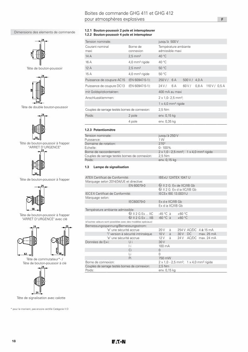
Tension nominale: jusqu’à 500 VCourant nominal maxi
Borne de connexion
Température ambiante admissible maxi
14 A 2,5 mm² 40 °C
16 A 4,0 mm² rigide 40 °C
12 A 2,5 mm² 50 °C
15 A 4,0 mm² rigide 50 °C
Puissance de coupure AC15 (EN 60947-5-1): 250 V / 6 A 500 V / 4,0 A
Puissance de coupure DC13 (EN 60947-5-1): 24 V / 6 A 60 V / 0,8 A 110 V / 0,5 A
mit Goldspitzkontakten: 400 mA au maxi
Anschlussklemmen: 2 x 1,0 - 2,5 mm²;
1 x 4,0 mm² rigide
Couples de serrage testés bornes de connexion: 2,5 Nm
Poids: 2 pole env. 0,15 kg
4 pole env. 0,35 kg
1.2.1 Bouton-poussoir 2 pole et interrupteurer 1.2.2 Bouton-poussoir 4 pole et interrupteur
1.2.3 Potentiomètre
Tension nominale: jusqu’à 250 VPuissance: 1 WDomaine de rotation: 270°Echelle: 0 - 100%Borne de raccordement: 2 x 1,0 - 2,5 mm²; 1 x 4,0 mm² rigideCouples de serrage testés bornes de connexion: 2,5 NmPoids: env. 0,15 kg
1.3 Lampe de signalisation
ATEX Certificat de Conformité: IBExU 12ATEX 1047 UMarquage selon 2014/34/UE et directive:
EN 60079-0 D II 2 G Ex de IIC/IIB GbD II 2 G Ex d ia IIC/IIB Gb
IECEX Certificat de Conformité: IECEx IBE 13.0031UMarquage selon:
IEC60079-0 Ex d e IIC/IIB GbEx d ia IIC/IIB Gb
Température ambiante admissible:D II 2 G Ex ... IIC -45 °C à +60 °CD II 2 G Ex ... IIB -60 °C à +60 °C
(d’autres valeurs sont possibles avec des modèles spéciaux)
Bemessungsspannung/Bemessungsstrom:"e" une sécurité accrue 20 V à 254 V AC/DC 4 à 15 mA"i" version à sécurité intrinsèque 10 V à 30 V DC max. 25 mA"e" une sécurité accrue 12 V à 24 V AC/DC max. 24 mA
Données de Ex-i: U i 30 VI i 100 mACi 0Li 0Pi 750 mW
Borne de connexion: 2 x 1,0 - 2,5 mm²; 1 x 4,0 mm² rigideCouples de serrage testés bornes de connexion: 2,5 NmPoids: env. 0,15 kg

19
F
Boites de commande GHG 411 et GHG 412 pour atmosphères explosives
Dimensions des elements de commande
2
1
Tête d'instrument de mesure AM 45
Tête d'instrument de mesure AM 72
Tête de commutateur de commande
X = dimensions de fixation
Fig. 1
1.6 Circuit à sécurité intrinsèque
1.5 Bornier
1.4 Instrument de mesure AM45 / AM72; Instrument de mesure VM45 / VM72
Attestation d’examen CE de type: BVS 14 ATEX E 125 U
Marquage selon 2014/34/UE et directive:
ferromagnétique D II 2 G Ex e IIC Gb
D II 2 G Ex e mb IIC Gb
magnéto-électrique D II 2 G Ex ib IIC Gb
IECEx Certificat de Conformité: IECEx BVS 14.0082U
Marquage selon:
ferromagnétique Ex e IIC Gb
Ex e mb IIC Gb
magnéto-électrique Ex ib IIC Gb
Température de fonctionnement: -55 °C et +55 °C
Tension nominale: 500 V au maxi
ferromagnétique magnéto-électrique
Justesse: Classe 2,5 Classe 1,5
Gamme de surcharge: fois à sec. fois à sec.
fois à sec.
fois à sec.
indicatif
Etendue de mesure:
direkt
Consommaton d’énergie:
Coil: tours
Résistance interne:
Li:
Ci:
Ui:
I i :
Borne de raccordement: fine / brin
rigide
Couples de serrage testés bornes de connexion:
Poids AM/VM 45
AM/VM 72
EN 60079-0
IEC 60079-0
10 - - 25 10 - - 5
25 - - 4
50 - - 1
1:1,5
AM: n / 1A 0 - 24 mA
0 - 25 A 4 - 24 mA
VM45: 6 - 415 V
VM72: 6 - 660 V
VM45: 0,91 - 1,76 VA
VM72: 0,91 - 2,65 VA
26,5
2,5 Ohm +- 30%
- max. 0,1 mH
- max. 0,1 nF
- max. 30 V
- max. 150 mA
2 x 0,5 - 2,5 mm²
1 x 4,0 mm²
2,5 Nm
env. 0,35 Kg
env. 0,40 Kg
Tension maximale pour sécurité technique Um: 690 Veff
isolation galvanique de tous les autres circuits à sécurité intrinsèque et de la terre
ATEX Certificat: SEV 13 ATEX 0178 U
Marquage selon 2014/34/UE et directive:
EN 60079-0 II 2 G Ex eb IIC
IECEx Certificat: IECEx SEV 13.0012 U
Marquage selon: IEC60079-0 Ex eb IIC
Type de borne: 6 x MUT 4
Tension nominale: jusqu’à 352 V
Section transversale du conducteur: 2 x 0,2 - 4,0 mm²
Couples de serrage testés bornes de connexion: 0,6 - 0,8 Nm
Poids: env. 0,08 kg

20
2 Consignes de sécurité
aGroupe cible: Électriciens et personnel qualifiés en conformité avec la législation et
les standards nationaux et, si applicable, en conformité avec CEI/EN 60079-14 sur les ins-tallations électriques pour les atmosphères explosives.
Les boites de commande GHG 411 et GHG 412 ne conviennent pas à un emploi en zone 0 et zone 20.
Le groupe d’explosion et la classe de température marqués sur les appareils devront être respectés.
Il n’est pas permis de transformer ou de modifier les boites de commande. Seuls des boites de commande intactes et parfaites devront être employées pour la fonction qui leur est dévolue.
Les exigences des CEI/EN 60079-31 en ce qui concerne des dépôts de poussière démesurés et une température doivent être considérées par I’utilisateur.
Seules des pièces de rechange homologuées d’origine CEAG devront être utilisées comme remplacement et pour des répa-ra-tions. Des réparations qui portent sur la protection contre l’explosion, ne devront être exécutées que par CEAG ou par un électricien qualifié en conformité avec la règlementation nationale en vigueur.
Avant la mise en service, les boites de commande doivent être vérifiées selon l’instruction donnée dans la section 6.
Respectez les prescriptions nationales de sécurité et de prévoyance contre les accidents ainsi que les consignes de sécurité figurant en italique dans ce mode d’emploi.
3 Conformité avec les normesLes Appareils sont conformes aux normes reprises dans la déclaration de conformité, jointe séparément.
Les références aux normes et directives dans cette notice se réfèrent toujours à la dernière version. Les suppléments éventuels doivent également être respectés.
4 Domaine d’utilisationCes boites de commande comportant les composants décrits dans le chapitre Caractéris-tiques techniques répondent aux exigences d’une utilisation en atmosphère explosible, zones 1, 2 ainsi que l’emploi en zones 21 et 22 selon la norme CEI/EN 60079-10-1 et CEI/EN 60079-10-2.
Pour l’enveloppe, et les pièces métalliques extérieures, des matières de qualité supérieure (polyamide anti-choc) qui assurent une protection appropriée contre la corrosion et une résistance aux agents chimiques en ”atmos-phère normale” ont été employées : -polyamide anti-choc -acier spécial AISI 316 L
En cas d‘utilisation en atmosphère extrème-ment corrosive, vous pouvez obtenir des informations complémentaires sur la résistance chimique des plastiques utilisés chez la succursale Cooper Crouse-Hinds de votre région.
5 Utilisation / PropriétésLes boites de commande GHG 411 et GHG 412 servent à la commande sur place d’installations électriques en atmosphère explosive.
Dépendant de l’emploi spécifique et suivant le cas, les appareils sont dotés des composants encastrés appropriés.
Des modèles spéciaux de boites de commande conçus sur demande peuvent être employés dans des circuits à sécurité intrinsèque.
Dans ce cas, les valeurs électriques limites de la sécurité intrinsèque sont à respecter.
Le modèle à pointes de contact or est employé pour la coupure de valeurs de tension peu élevées. La tension maximale admise doit être observée (voir page 17, Caractéristiques techniques). Ce modèle est reconnaissable au marquage ”G” sur le socle.
Afin d’obtenir une déconnexion fiable, des contacts de rupture forcée ont été montés comme contacts normaux.
Suivant le cas, les socles sont aussi dotés de résistances de 0,6 W, de fusibles pour faible intensité et des diodes (puissance dissipée de 1 W maxi).
L’instrument de mesure AM/VM72 et AM/VM45 sert à l’indication sur place des grandeurs électriques. Le type du mécanisme de mesure, la justesse et le type de raccordement sont indi-qués dans les caractéristiques techniques.
En cas d’instruments de mesure pour connexion au transformateur d’intensité n/1A (fig. 1, pos. 2), un volet disposé sur la partie supérieure de l’instrument de mesure permet d’échanger les cadrans interchangeables (fig. 1, pos. 1).
Si le collet de commutation des manipulateurs est découpé à la position de verrouillage respective, il est possible de les cadenasser dans cette position (Ø de l’étrier jusqu’à 5 mm).
F
Boites de commande GHG 411 et GHG 412 pour atmosphères explosives

21
On peut actionner 4 bases de traceur de pression polige avec le type d'état CCH résolutions de contrôle. Si 4 bases de traceur de pression polige avec un traceur d'impact la résolution doit être actionnée avec des Verrastung, cette résolution doit être équipée avec un Verrastung renforcée.
Cette résolution est à la glace d'impact rouge avec des panneaux d'insertion noirs de manière perceptible et p. ex. sous le CCH un numéro d'article GHG 410 1437R….
a Pour l’emploi, les consignes des sections 3 et 4 devront être respectées.
a Des emplois autres que ceux décrits ne sont admis qu’avec le consentement par écrit de la part de CEAG.
a Lors de l’exploitation, les instructions selon point 7 de ce mode d’emploi doivent être respectées.
a Seul l’utilisateur est responsable de l’emploi comme prévu de cette boites de commande, en tenant compte des condi-tions générales existant dans l’établisse-ment (voir Caractéristiques techniques).
6 InstallationPour l’installation et l’exploitation de ces appareils, la règlementation nationale en vigueur (en Allemagne par ex. Betr.Si.V, loi de sécurité des appareils) ainsi que les règles de la technique généralement reconnues devront être respectées (CEI/EN 60079-14).
a L’installation incorrecte de ces boites à commande peut annuler la garantie.
6.1 Montage
Le montage des boites de commande GHG 411 peut se faire sans ouvrir l’enveloppe.
En cas de montage directement au mur, les boites de commande ne doivent reposer au niveau du mur que dans les points de fixation prévus. La vis choisie doit être en rapport avec le trou de fixation (voir plan coté, page 17).
Elle ne doit pas avarier le trou (par ex. emploi d’une rondelle).
a Si les vis sont forcées, l’appareil peut être avarié.
Les boites de commande GHG 411 peuvent être montées sur des porte-appareils COOPER Crouse-Hinds au moyen des vis autotarau-deuses, voir page 23).
Les instructions respectives pour le montage devront être respectées.
Le montage des boites de commande GHG 412 peut se faire grâce au gabarit de perçage prévu à cet effet (voir page 17).
Ce faisant, on veillera à l’efficacité de la surface de fermeture et au bon état du joint qui est appliqué sur le couvercle de l’appareil.
La fixation de la boite de commande dans la plaque se fait par l’arrière de celle-ci, au moyen des ergots prévus à cet effet. Ces derniers seront fixés par 2 vis sur la partie arrière de la boite.
6.2 Ouverture de l’appareil / Raccordement électrique
a Avant ouverture des boitiers, on s’assurera de la mise hors tension et de la prise de mesures de sécurité.
a Le raccordement électrique de l’appareil ne doit se faire que par du personnel qualifié (CEI/EN 60079-14).
En tenant compte des règlements respectifs, les conducteurs dûment dénudés des câbles sont raccordés. En cas d’utilisation de câbles de connexion multifilaires ou à fils de petit diamètre, les extrémités des fils doivent être traitées selon la règlementation nationale et internationale applicable (par ex. emploi des embouts).
a Afin de maintenir le mode de protection, la connexion des conducteurs doit se faire très soigneusement. L’isolation doit couvrir le conducteur jusqu’à la borne. Le conduc-teur lui-même ne doit pas être endommagé.
a Si l’appareil comporte des composants Ex-i et Ex-e, les distances minimales requises sont à respecter (voir par ex. CEI/EN 60079-11). On s’assurera qu’il n’y a aucun reste de tension dans les circuits à sécurité intrinsèque lorsque l’appareil est ouvert.
Les instructions pour le montage du matériel électrique à sécurité intrinsèque doivent être respectées.
Il faut assurer que la capacitance et l’inductance extérieures admissibles pour le circuit spécifique à sécurité intrinsèque ne soient pas dépassées.
Les sections minimales et maximales admissibles des conducteurs doivent être respectées (voir caractéristiques techniques).
Schémas de connexion 1 x 4 pole
Schémas de connexion 2 x 2 pole
Têtede bouton-poussoir à frapper GHG 410 1437R....
21
22 44
43
R1
34
3311
12
44
43
R2
34
33
24
23
14
13
21
22
R3
11
12
41
42
31
32
44
43
R4
34
33
24
2311
12
21
22
R5
11
12
31
32 44
43
S 1
S 2S 4
S 3
S 2S 4
S 3
S4
S 1
21
22 44
43
R1
34
3311
12
44
43
R2
34
33
24
23
14
13
21
22
R3
11
12
41
42
31
32
44
43
R4
34
33
24
2311
12
21
22
R5
11
12
31
32 44
43
S2 S3S1
Glace d’impactROUGE
Panneaux d’insertion
noir
base jaune
S4S2 S3S1
F
Boites de commande GHG 411 et GHG 412 pour atmosphères explosives
22
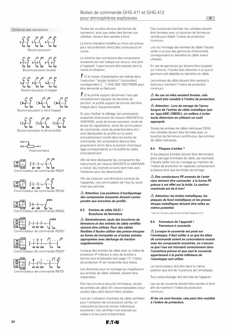
Schémas des connexions Toutes les vis et/ou écrous des bornes de connexion, ainsi que celles des bornes non utilisées, doivent être serrées à fond.
La borne standard installée au choix est prévue pour raccordement direct des conducteurs en cuivre.
Le schéma des connexions des composants encastrés est soit indiqué sur ceux-ci, soit joint à l’appareil. Il peut encore être exposé dans la notice d’utilisation.
! Si le moyen d’exploitation est réalisé dans l’exécution ”double isolation“, l’autocollant correspondant ( ) GHG 905 1002 P0005 peut être demandé au fabricant.
! Si le profilé support de bornes n’est pas complètement équipés de barrettes de jonction, le profilé support de bornes doit être intégré dans l’équipotentialité.
Si, pour faciliter le câblage, les composants encastrés (instrument de mesure AM/VM72 et AM/VM45, socle de bouton-poussoir, socle de lampe de signalisation, socle de commutateur de commande, socle de potentiomètre etc.) sont décliquetés du profilé sur le cadre d’encastrement monté dans les boites de commande, les composants devront être proprement remis dans la position d’enclique-tage correspondante sur le profilé du cadre d’encastrement.
Afin de faire décliqueter les composants (les instruments de mesure AM/VM72 et AM/VM45 y inclus), les crochets à crans sont tirés vers l’extérieur pour les déverrouiller.
Afin de s’assurer une fermeture correcte de l'appareils, une commutation de l’axe du socle n’est pas permise.
a Attention: Les positions d’encliquetage des composants encastrés doivent corres-pondre aux encoches du profilé .
6.3 Entrées de câble (KLE) / Bouchons de fermeture
a Généralement, seuls des bouchons de fermeture et des entrées de câble certifiés doivent être utilisés. Pour des câbles flexibles il faudra utiliser des presse-étoupes en forme de trompette ou d’autres entrées appropriées avec décharge de traction supplémentaire.
Lorsque des entrées de câble avec un indice de protection IP inférieur à celui de la boîte à bornes sont employées (voir page 17), l’indice de protection IP de l’ensemble sera réduit.
Les directives pour le montage qui s’appliquent aux entrées de câble utilisées, doivent être respectées.
Pour les circuits à sécurité intrinsèque, seules les entrées de câble EX-i (reconnaissables à leur couleur bleu clair) devront être utilisées.
Lors de l’utilisation d’entrées de câble certifiées pour l’utilisation de conducteurs serrés, on s’assurera qu’aucune torsion mécanique excessive / non certifiée n’est exercée sur celles-ci et les joints d’étanchéité.
Des ouvertures d’entrée non utilisées doivent être fermées avec un bouchon de fermeture certifié pour établir l’indice de protection minimum.
Lors du montage des entrées de câble il faudra veiller à ce que des garnitures d’étanchéité correspondant au diamètre du câble soient utilisées.
En cas de garnitures qui doivent être coupées sur mesure, il faudra faire attention à ce que la garniture soit adaptée au diamètre du câble.
Les entrées de câble doivent être serrées à fond pour maintenir l’indice de protection minimum.
a Au cas où elles seraient forcées, cela pourrait être nuisible à l’indice de protection.
a Attention : Lors du serrage de l’écrou borgne de l’entrée de câble métallique (par ex. type ADE; CMDEL), on veillera à éviter toute distorsion en utilisant un outil approprié.
Toutes les entrées de câble métriques CEAG non utilisées doivent être fermées avec un bouchon de fermeture certifié pour des entrées de câble métriques.
6.4 Plaques à brides *
Si les plaques à brides doivent être démontées (pour percage d’entrées de câble, par exemple) il faudra veiller lors du montage au maintien de l’indice de protection en replacant correctement la plaque ainsi que les brides de serrage.
a Des conducteurs PE amenés de l’exté-rieur doivent être connectés à la borne PE prévue à cet effet sur la bride. La section maximale est de 6 mm²
a Attention: les brides métalliques, les plaques de fond métalliques et les presse-étoupe métalliques doivent être reliés au même potentiel.
* pour le moment, pas encore certifié Catégorie II D
6.5 Fermeture de l’appareil / Fermeture à couvercle
a Lorsque le couvercle est posé sur l’enveloppe, il faut veiller à ce que les têtes de commande soient en concordance exacte avec les composants encastrés, on s’assure-ra que l’axe est introduit correctement dans l’ouverture prévue et que seul le couvercle appartenant à la partie inférieure de l’enveloppe soit utilisé.
Le commutateur doit être dans la même position que lors de l’ouverture de l’enveloppe.
Tout corps étranger doit être ôté de l’appareil.
Les vis de couvercle doivent être serrées à fond afin de maintenir l’indice de protection minimum.
Si les vis sont forcées, cela peut être nuisible à l’indice de protection.
Bouton-poussoir
Bouton-poussoir double
Bouton-poussoir à frapper
Bouton-poussoir à clé à frapper
Bouton-poussoir à clé amovible
Potentiomètre
Commutateur de commande R6201
Commutateur de commande R6102
Commutateur de commande R6002
Commutateur de commande R5307
Commutateur de commande R5507
Commutateur de commande R8701
F
Boites de commande GHG 411 et GHG 412 pour atmosphères explosives

23
Trous de fixation sur porte-appareils taille 1
Trous de fixation sur porte-appareils taille 2
8 Réparations / Remise en étatDes réparations ne doivent être exécutées qu’à l’aide des pièces de rechange d’origine CEAG.
a En cas de défauts sur l’enveloppe antidéflagrante, seul un remplacement est admissible. Dans le doute, l’appareil défectueux devra être renvoyé à CEAG pour réparation.
a Des réparations qui portent sur la protection contre l’explosion, ne devront être exécutées que par COOPER Crouse-Hinds ou par un électricien qualifié en conformité avec la règlementation nationale en vigueur (CEI/EN 60079-19).
Il n’est pas permis de transformer ou de modifier ces appareils, sauf pour le montage des entrées de câble supplémentaires en conformité avec leur homologation.
Pour remplacer des composants encastrés individuels (instrument de mesure, bou-ton-poussoir etc.), l’alinéa 6.2 „Ouverture de l’appareil/Raccordement électrique“ devra être respecté.
9 Évacuation des déchets / RecyclageLors de l’évacuation de ce matériel électrique, la règlementation nationale respective en vigueur devra être respectée.
Pour faciliter la réutilisation des composants individuels, des pièces en matière plastique ont été repérées de la marque distinctive de la matière plastique employée.
Sous réserve de modification ou d’informations supplémentaires..
6.6 Mise en service
Avant la mise en service de l’appareil, les vérifications spécifiées dans les règlements nationaux individuels devront être exécutées.
De plus, on vérifiera que son fonctionnement et son installation sont correcte de telle sorte à respecter les instructions de ce mode d’emploi et des autres règlements applicables
Avant la mise en service, le positionnement à zéro de l’aiguille devra être vérifié. Le cas échéant, on utilisera la vis de réglage.
La classification du gaz (II B ou II C) du circuit à sécurité intrinsèque est à prendre en compte pour le classement des composants encastrés.
a L’utilisation incorrecte de ces boites à bornes peut annuler la garantie.
7 Maintien / EntretienLa règlementation nationale en vigueur pour le maintien et l’entretien du matériel électrique pour atmosphère explosive doit être respectée. (en CEI/EN 60079-17).
Avant d’ouvrir l’enveloppe, débrancher l’appareil de la tension ou prendre des mesures préventives appropriées.
En cas de circuits à sécurité intrinsèque, des travaux sont permis sous tension.
Les intervalles de service requis dépendent de l’emploi spécifique et devront donc être fixés par l’utilisateur en tenant compte des condi-tions d’utilisation.
Lors de l’entretien des commutateurs, surtout les composants qui sont essentiels à leur mode de protection contre l’explosion, doivent être vérifiés (par ex. intégrité des composants antidéflagrants et du boitier, efficacité des joints de couvercle et resserrement des entrées de câble) ainsi que le fonctionnement du méca-nisme de commutation.
Si, lors d’un entretien, on constate que des travaux d’entretien sont nécessaires, il faudra suivre le point 8 de ce mode d’emploi.
Porte-appareil pour fixation au mur et sur grillage
Porte-appareil pour fixation au mur et sur grillage
Trous defixation pourboite de commandeGHG 411 81
Porte-appareil pour fixation aux tubes
Porte-appareil pour fixation aux tubes
Trous de fixation pour boite de commande GHG 411 82
Trous de fixation pour boite de commande
GHG 411 83
F
Boites de commande GHG 411 et GHG 412 pour atmosphères explosives

Publication No. GHG 410 7001 P0001 D/E/F (r) / Auflage 01.2016/MS
Eaton is a registered trademark.
All trademarks are property of their respective owners.
Eaton is dedicated to ensuring that reliable, efficient and safe power is available when it’s needed most. With unparalleled knowledge of electrical power management across industries, experts at Eaton deliver customized, integrated solutions to solve our customers’ most critical challenges.
Our focus is on delivering the right solution for the applica-tion. But, decision makers demand more than just innovative products. They turn to Eaton for an unwavering commitment to personal support that makes customer success a top priority. For more information, visit
www.eaton.com/electrical.
Changes to the products, to the information contained in this document, and to prices are reserved; so are errors and omissions. Only order confirmations and technical documentation by Eaton is binding. Photos and pictures also do not warrant a specific layout or functionality. Their use in whatever form is subject to prior approval by Eaton. The same applies to Trademarks (especially Eaton, Moeller, and Cutler-Hammer). The Terms and Conditions of Eaton apply, as referenced on Eaton Internet pages and Eaton order confirmations.
CZ: "Tento návod k použití si m žete vyžádatve svém mate ském jazyce u p íslušnéhozastoupení spole nosti Cooper Crouse-Hinds/CEAG ve vaší zemi."
DK: "Montagevejledningen kan oversættes tilandre EU-sprog og rekvireres hos DeresCooper Crouse-Hinds/CEAG leverandør"
E: "En caso necesario podrá solicitar de surepresentante Cooper Crouse-Hinds/CEAGestas instrucciones de servicio en otro idiomade la Union Europea"
EST: "Seda kasutusjuhendit oma riigikeelesvõite küsida oma riigis asuvast asjaomasestCooper Crouse-Hindsi/CEAG esindusest."
FIN: "Tarvittaessa tämän käyttöohjeen käännöson saatavissa toisella EU:n kielellä TeidänCooper Crouse-Hinds/CEAG - edustajaltanne"
GR:
Cooper Crouse-Hinds/CEAG"
H: "A kezelési útmutatót az adott országnyelvén a Cooper Crouse-Hinds/CEAG céghelyi képviseletén igényelheti meg."
I: "Se desiderate la traduzione del manualeoperativo in un´altra lingua della Comunit àEuropea potete richiederla al vostrorappresentante Cooper Crouse-Hinds/CEAG"
LT: Šios naudojimo instrukcijos, išverstos J sugimt j kalb , galite pareikalauti atsakingoje"Cooper Crouse-Hinds/CEAG" atstovyb je savošalyje.
LV: "Šo ekspluat cijas instrukciju valsts valodvarat piepras t j su valsts atbild gaj CooperCrouse-Hinds/CEAG p rst vniec b ."
M: Jistg u jitolbu dan il-manwal fil-lingwanazzjonali tag hom ming and ir-rappre entantta' Cooper Crouse Hinds/CEAG f'pajji hom.
NL: "Indien noodzakelijk kan de vertaling vandeze gebruiksinstructie in een andere EU-taalworden opgevraagd bij Uw Cooper Crouse-Hinds/CEAG - vertegenwoordiging"
P: "Se for necessária a tradução destasinstruções de operação para outro idioma daUnião Europeia, pode solicita-la junto do seurepresentante Cooper Crouse-Hinds/CEAG"PL: Niniejsz instrukcj obs ugi w odpowiedniejwersji j zykowej mo na zamówi wprzedstawicielstwie firmy Cooper-Crouse-Hinds/CEAG na dany kraj.
S: "En översättning av denna montage- ochskötselinstruktion till annat EU - språk kan vidbehov beställas från Er Cooper Crouse-Hinds/CEAG- representant"
SK: "Tento návod na obsluhu Vám vo Vašomrodnom jazyku poskytne zastúpenie spolo nostiCooper Crouse-Hinds/CEAG vo Vašej krajine."
SLO: "Navodila za uporabo v Vašem jezikulahko zahtevate pri pristojnem zastopništvupodjetja Cooper Crouse-Hinds/CEAG v Vašidržavi."
RUS: "При необходимости, вы можете запрашивать перевод данного руководства на другом языке ЕС или на русском от вашего Cooper Crouse-Хиндс / CEAG - представителей."