gfrp bars for internal reinforcement of … · 191 studies and researches – v.34, 2015 graduate...
TRANSCRIPT

191
STUDIES AND RESEARCHES – V.34, 2015 Graduate School in Concrete Structures – Fratelli Pesenti Politecnico di Milano, Italy
GFRP BARS FOR INTERNAL REINFORCEMENT OF CONCRETE STRUCTURES
Giulia Fava1, Massimiliano Bocciarelli2, Valter Carvelli2, Marco Andrea Pisani3, Carlo Poggi3
ABSTRACT
This paper presents the activities developed at Politecnico di Milano that deal with the use of glass fibre reinforced polymers (GFRP) rebars for the internal reinforcement of concrete structural elements.
Problems related to experimental characterization of the rebars, to bond of GFRP rebars and concrete, to fatigue of GFRP reinforced slabs and to the effect of elevated temperature on GFRP reinforced beams are discussed after showing the outcomes of the experimental tests conducted.
All these studies support the view that GFRP rebars can be used profitably in some structural elements particularly exposed to corrosion.
Keywords: GFRP bars, Reinforced concrete, Mechanical properties.
1 Assistant Professor – Department of Architecture, Built Environment and Construction Engineering – ABC, Politecnico di Milano, Milan (Italy).
2 Associate Professor, Department of Architecture, Built Environment and Construction Engineering – ABC, Politecnico di Milano, Milan (Italy). 3 Professor, Department of Architecture, Built Environment and Construction Engineering – ABC, Politecnico di Milano, Milan (Italy).

192
1. INTRODUCTION Steel rebars are the tension device usually adopted worldwide in reinforced concrete. There are anyway few special conditions where the adoption of GFRP (Glass Fibre Reinforced Polymer) rebars can be advantageous (Rostàsy et al, 1993; Bakis et al, 2002).
GFRP rebars are commonly adopted in Tunnel Boring Machine “soft-eye” openings for launch and reception because of their brittleness and weakness when impacted by the cutting shield of the TBO
Nevertheless, the main application of these rebars refers to structural elements in severe environmental conditions. This is due to the excellent corrosion resistance to salt water of GFRP rebars have and the good behaviour at low temperature. Because of this, GFRP rebars could be adopted to increase durability of concrete structures exposed to de-icing chlorides, i.e.: • bridge decks and railings, • median barriers, • approach slabs, • salt storage facilities, • continuously reinforced concrete paving, • some precast elements like culverts and rail grade crossings, or to marine chlorides, that is: • sea walls, wharfs, quays and dry docks, • coastal construction exposed to salt fog, • desalinization intakes, • port aprons.
Canadians build bridge slabs reinforced with GFRP rebars from the early nineties (see Mufti et al, 2008 and Pendhari et al, 2008) and the advantages of these composite rebars have been already demonstrated, although some aspects concerning for instance bond to concrete, durability of the rebars, fatigue behaviour and reaction to fire still need more in-depth investigation.
This paper is intended to describe the research carried out and experience gained at Politecnico di Milano on this particular type of rebar. 2. MATERIALS EXPERIMENTAL CHARACTERIZATION The manufacturing technique generally adopted to produce fibre reinforced polymer rebars is pultrusion: the fibres are taken directly from the rovings and conveyed to a resin bath where impregnation occurs. Bundles of impregnated fibres enter the heating die where the material is formed. The thermosetting resin is then hardened by means of heating (generally supplied by electrical resistances and the temperature is controlled by means of thermocouples). Upon exiting from the heating die, the matrix is cured and the composite is pulled at a constant speed. At the end of the process the material is cut to the appropriate length.
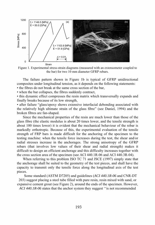
The tensile behaviour of a GFRP rebar is elastic/brittle, as shown in Figure 1a.
193
Figure 1. Experimental stress-strain diagrams (measured with an extensometer coupled to
the bar) for two 10 mm diameter GFRP rebars.
The failure pattern shown in Figure 1b is typical of GFRP unidirectional composites under longitudinal tension, as it depends on the following statements: • the fibres do not break at the same cross section of the bar, • when the bar collapses, the fibres suddenly contract, • this dynamic effect compresses the resin matrix which transversally expands and finally breaks because of its low strength, • after failure “glass/epoxy shows extensive interfacial debonding associated with the relatively high ultimate strain of the glass fibre” (see Daniel, 1994) and the broken fibres are fan-shaped.
Since the mechanical properties of the resin are much lower than those of the glass fibre (the elastic modulus is about 20 times lower, and the tensile strength is about 100 times lower) it is evident that the mechanical behaviour of the rebar is markedly orthotropic. Because of this, the experimental evaluation of the tensile strength of FRP bars is made difficult for the anchoring of the specimen to the testing machine: when the tensile force increases during the test, the shear and/or radial stresses increase in the anchorages. The strong anisotropy of the GFRP rebars (that involves low values of their shear and radial strength) makes it difficult to design an efficient anchorage and this difficulty increases together with the cross section area of the specimen (see ACI 440.1R-06 and ACI 440.3R-04).
When referring to this problem ISO TC 71 and JSCE (1997) simply state that the anchorage shall be suited to the geometry of the test pieces, and shall have the capacity to transmit only the tensile force along the longitudinal axis of the test pieces.
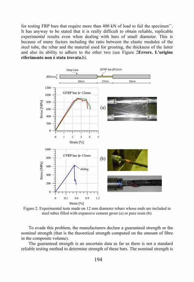
Some standard (ASTM D7205) and guidelines (ACI 440.1R-06 and CNR-DT 203) suggest placing a steel tube filled with pure resin, resin mixed with sand, or
expansive cement grout (see Figure 2), around the ends of the specimen. However, ACI 440.1R-06 states that the anchor system they suggest ‘‘is not recommended
194
for testing FRP bars that require more than 400 kN of load to fail the specimen’’. It has anyway to be stated that it is really difficult to obtain reliable, replicable experimental results even when dealing with bars of small diameter. This is because of many factors including the ratio between the elastic modules of the steel tube, the rebar and the material used for grouting, the thickness of the latter and also its ability to adhere to the other two (see Figure 2Errore. L'origine riferimento non è stata trovata.b).
Figure 2. Experimental tests made on 12 mm diameter rebars whose ends are included in
steel tubes filled with expansive cement grout (a) or pure resin (b).
To evade this problem, the manufacturers declare a guaranteed strength or the nominal strength (that is the theoretical strength computed on the amount of fibre in the composite volume).
The guaranteed strength is an uncertain data as far as there is not a standard reliable testing method to determine strength of these bars. The nominal strength is

195
meaningless because the bar strength strongly depends on the resin adopted, the manufacturing method (that governs the parallelism and distribution of the fibres inside the polymeric matrix) and the bar diameter (ACI 440.1R-06 states that ‘‘GFRP bars from three different manufacturers show tensile strength reductions of up to 40% as the diameter increases proportionally from 0.375 to 0.875 in.’’).
To overcome these difficulties a new anchor system that makes it possible tension testing of large diameter GFRP bars in a universal testing machine was developed (Carvelli et al, 2009 and Fava et al, 2012).
The anchor body designed consists of two shells, pushed one against the other by the jaws of the testing machine, leaving an inner conical hole. The ends of the bar are equipped with resin heads having the shape of the hole inside the anchor body (see Figure 3).The adopted resin is a mix of orthophtalic unsaturated polyester high reactive resin and quartz sand (grains range is 0.2–0.3 mm). The ratio of sand to resin by weight is 210% (sand may break apart when over-mixing). Quartz sand has to be wormed up to 45°C before mixing it with the resin to get a homogeneous and low viscous mixture.
Figure 3. Geometry of the anchor system suggested in Carvelli et al, 2009.
The mean value of the tensile strength of this resin mixture is 10.2 MPa and the tensile Young modulus measured is 3.1 GPa, whereas the mean value of the compressive strength is 72.2 MPa.
The concept that ruled the design of the anchoring system is that the resin head is dragged inside the conical hole because of its adhesion to the surface of the bar.

196
The resin heads are covered with grease to minimize friction with the inner surface of the anchor body and, therefore, facilitate this mechanical behaviour.
When the tensile stress increases in the bar, the resin head is pushed inside the conical hole, causing an increase of the radial pressure and of the adhesion to the surface of the bar.
The purpose of the overhanging rear region is to increase the bond surface and to create a pressure on the rear base of the cone placed inside the anchor body.
This anchor system demonstrated to be effective in performing tension testing of GFRP bars having a diameter between 12 mm and 28 mm, that is bars whose theoretical failure load is in the range between 100 kN and 600 kN.
A crucial point to be successful in the tests concerns the distribution of contact pressure between the resin heads and the conical hole inside the anchor body. The volume of the resin head changes during hardening, therefore adjustments had to be made to the mould before the resin head fitted the conical seat inside the anchor body. Despite the excellent ability to replicate the experimental results, it has to be mentioned that the problem of the dependence of the shape of the mould on the exact inner shape of the shells of a specific testing machine has limited up to now the diffusion of this testing method.
3. BOND OF GFRP REBARS AND CONCRETE When GFRP rebars are used as internal reinforcements in concrete, debonding is not allowed among the collapse mechanisms, as stated in the Eurocode 2, where it is required that “the ultimate bond strength shall be sufficient to prevent bond failure” (EN 1992-1-2, 2005). From this point of view, in the past years both manufacturers and researchers have been analysing the way to improve the bond strength of GFRP (glass fibre reinforced polymer) rebars in concrete, as an effective alternative to steel rebars in reinforcing concrete structural elements.
As pultruded GFRP rebars are significantly orthotropic materials with high strength unidirectional fibres placed inside a low strength polymeric matrix, attaining suitable bond strength is quite troublesome. An efficient method to achieve good bond strength is to coat their surface with coarse quartz sand (Baena et al., 2009). Another way to increase the bond strength of GFRP rebars consists on wrapping a helical yarn around the bar before resin polymerization to obtain a corrugated surface or on producing an external ribbed surface bar after curing.
In this Section the results of an extensive investigation on the bond behaviour of GFRP rebars embedded in concrete is presented. Pull-out tests were performed on helically wrapped and sand coated GFRP rebars with a wide range of diameters. Finally, the development length of FRP bars suggested in some design codes is discussed.
The GFRP bars considered in the investigation had nominal diameters of 8, 10, 12, 16, 20 and 25 mm. The bars were made of unidirectional E-glass fibres and vynilester resin. In the manufacturing process, the bars were firstly pultruded and
197
then wrapped. Indeed, the external surface had a spiral aramidic yarn wound along the length and was sand coated with quartz to increase the bond to concrete.
The mechanical properties of the bars were verified experimentally (Carvelli et al., 2009). The average (three tests for each diameter) longitudinal tensile strengths of the bars were of 885 MPa, 1071 MPa for diameters of 16 mm and 20 mm, respectively. The elastic modulus for all diameters was equal to 39 GPa.
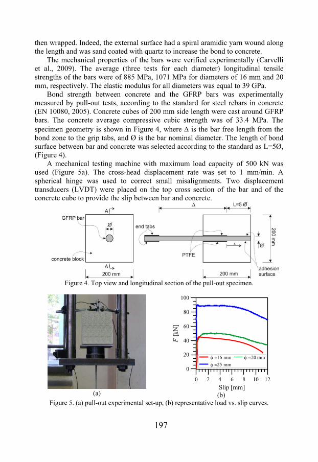
Bond strength between concrete and the GFRP bars was experimentally measured by pull-out tests, according to the standard for steel rebars in concrete (EN 10080, 2005). Concrete cubes of 200 mm side length were cast around GFRP bars. The concrete average compressive cubic strength was of 33.4 MPa. The specimen geometry is shown in Figure 4, where is the bar free length from the bond zone to the grip tabs, and Ø is the bar nominal diameter. The length of bond surface between bar and concrete was selected according to the standard as L=5Ø, (Figure 4).
A mechanical testing machine with maximum load capacity of 500 kN was used (Figure 5a). The cross-head displacement rate was set to 1 mm/min. A spherical hinge was used to correct small misalignments. Two displacement transducers (LVDT) were placed on the top cross section of the bar and of the concrete cube to provide the slip between bar and concrete.
Figure 4. Top view and longitudinal section of the pull-out specimen.
(a)
0 2 4 6 8 10 12
Slip [mm]
0
20
40
60
80
100
F[k
N]
16 mm
25 mm
20 mm
(b)
Figure 5. (a) pull-out experimental set-up, (b) representative load vs. slip curves.

198
The similarities and discrepancies between the bond behaviour of GFRP and steel bars in concrete are shown in Figure 6a. For the same geometry of the pull-out specimen, the same concrete quality and experimental setup, the maximum average adhesive shear stresses for the GFRP rebars are compared to those of some steel rebars (Figure 6a). For the considered diameters GFRP bars are found to ensure bond strength of the same level of the steel ones. The main difference between the GFRP and steel bond to concrete is related to the failure mode.
For all the GFRP bars, the bond failed at the interface (Figure 6b). The external layer of the bars, including the spiral aramidic yarn and quartz sand, was completely detached. The steel bars of lower diameters generated interfacial failure with concrete, while concrete cube splitting was observed for bigger diameters.
Based on the experimental evidences a question concerning the optimal value of the development length for a GFRP rebar embedded in concrete arises. In fact, as the strength of a GFRP rebar approximately doubles the one of steel rebars and considering that the experimental data show that the bong strength of GFRP bars are similar to the values for steel rebars, one could argue whether the development length of GFRP reinforcement should double too.
8 10 12 16 20 25
Bar diameter [mm]
0
5
10
15
20
max
[MP
a]
GFRPSteel
(a)
(b)
Figure 6. (a) maximum average adhesive shear stresses for bar nominal diameter, (b) typical failure mode for pull-out specimens with GFRP bars.
From the design point of view, the fib bulletin 40 (fib, 2007) provides expressions for evaluating the development length of FRP reinforcing bars in concrete and ensuring a successful transfer of forces from concrete to the reinforcement. Analytical bond evaluation in concrete elements are based on both the Japan Society for Civil Engineering (JSCE, 1997) and American Concrete Institute (ACI 440.1R) design recommendations. In both cases, the design of concrete structural elements with FRP bars is an extension of the requirements for

199
steel reinforced structures and it is stated that the development length should be properly defined to avoid splitting.
Besides, in (JSCE, 1997) it is stated that, as a general rule, the basic development length of a FRP bar embedded in concrete should be experimentally obtained. Nonetheless, as experimentally observed, the bond interaction and failure of FRP bars is different from that of steel bars. In steel bars the interaction is mainly due to the mechanical action of the bar lugs against concrete and, once the concrete tensile stress is exceeded, cracks develop and propagate in the concrete substrate. On the other hand, when FRP bars are used, the bond interaction is primarily due to friction.
The experimental outcomes and the observations concerning the current codes allow to consider that: (a) in all the design formulae the development length is always influenced by the concrete compressive strength even if under certain conditions concrete splitting is not observed (Carvelli et al, 2010) and (b) that the bond strength is a function of the ratio between the concrete cover and the bar diameter irrespectively of the failure mode. All these remarks suggest that the determination of the development length of FRP rebars is very complex and still an unsolved point. Great merit must be allowed to the mentioned codes for providing a method to evaluate the development length and for pointing out the importance of such topic, but there is still a need to revise the existing formulae in order to propose more realistic and effective expressions. This will increase the confidence in using FRP reinforcement in concrete structural elements. 4. FATIGUE OF GFRP REINFORCED SLABS The durability of bridge decks is often affected by the corrosion of steel reinforcing bars in several cold countries, where de-icing is traditionally done with salt along with sand and gravel. The corrosion of steel rebars causes cracking and spalling of concrete bridge decks with consequent elevated costs for rehabilitation and traffic disruption. The possibility to replace steel rebars with GFRP rebars (that resist fairly well to salt water), as reinforcement of concrete bridge slabs, is an effective alternative to increase their service life in these unfavourable conditions (Hejlla, 2006).
The deck slabs sustain the moving loads representing the wheels of the vehicles, and are therefore susceptible to fatigue damage. Several researches were carried out to study the effects of the travelling concentrated loads on traditional concrete decks reinforced with steel bars (Pardikaris et al., 1988), while few were dedicated to full scale bridge deck slabs reinforced with GFRP bars (El-Ragaby, 2007).
The experimental investigation, here briefly presented (more details in Carvelli et al, 2010), aimed to understand the mechanical behaviour under cyclic (moving) loading of full scale bridge slab prototypes reinforced with GFRP bars and to verify the accuracy of the rules suggested by the European Codes to these bridge deck slabs.

200
The European codes (EN 1991-2, EN 1992-2) were adopted in the design process to define the acting loads and the mechanical properties of concrete.
The dimensions of the specimens (Figure 7) are representative of a full scale bridge deck adopted in stringer bridges, girder and crossbeam systems. The ratio between the distance of a free edge from the border of the nearest loading device (that simulates the contact area of the wheel of a lorry) and the centre-to-centre distance of the supports (which simulate the bridge beams) is 2050/1500=1.37. The ratio between the centre-to-centre distance of the supports and the deck thickness, equal to 1500/200=7.5, should minimize the arch effect inside the specimen. The two overhangs, 490 mm long, guarantee a suitable anchorage of the straight GFRP reinforcing bars and allow easy road haulage.
The European code (EN 1991-2) defines five fatigue load models. The maximum wheel load among them is 95 kN. It was decided to adopt a 140 kN load (that is a load 1.5 times the maximum one imposed by the codes) to design the specimens. Moreover, the wheel contact area adopted is 200300 mm, that is a contact area markedly lower than that of a 95 kN twinned wheel (400600 mm). These assumptions allowed reducing the collapse number of cycles during the experimental tests.
Figure 7. Specimen dimensions and reinforcement.

201
The GFRP rebars adopted were manufactured by combining the pultrusion process with a wrapping process, as described above. The external surface of the rebar is wrapped by aramidic yarn along the length of the bar and then sanded by quartz particles to increase bond to concrete. The mean strength of 16 mm diameter rebars of this kind was 885 MPa while the mean longitudinal elastic modulus was 39 GPa (Carvelli et al, 2009). Due to the low longitudinal elastic modulus, under the service load, the maximum displacement was set 1/250 of the centre-to-centre distance of the supports that is 6 mm. In other words, the bottom reinforcement is set to guarantee the durability of the asphalt concrete usually placed over the bridge deck, whereas the same amount of reinforcement is overabundant when referring to the bending strength of the slab.
Concrete of quality C55/67 was considered with mean cylindrical strength of 63 MPa and nominal (design) strength 36.7 MPa. This concrete, according to the European codes (Palmgren-Miner rule), fails after almost 1.13 million constant amplitude cycles (140 kN load applied on 200300 mm contact area).
The experimental setup aims to reproduce as close as possible the working features of a concrete bridge slab. The slabs were constrained by two longitudinal beams (length 5.1m) to simulate a simply support boundary condition (Figure 8). On the top side of the beams two continuous steel half cylinder (diameter 50mm) were welded to produce the supporting lines.
The loading condition of a travelling lorry wheel, according to the European codes, was reproduced by two hydraulic jacks whose axes were perpendicular to the slab longitudinal mid line. The jacks were positioned at a distance of 700mm (Figure 8), between them and the slab two laminated neoprene prismatic blocks were placed to produce a contact surface of 300200mm. To simulate the lorry wheel movement, the load cycle of each jack was defined setting as phase shift one quarter of cycle to have the maximum load of first jack when the second jack is at the minimum.
The mid span displacement was measured using five transducers (LVDTs) placed along the bottom mid span line of the slab.
Figure 8. Experimental setup.

202
Three slabs (S1, S2 and S3) were cyclically loaded according to the maximum load in the cycle listed in Table 1. Slabs S1 and S2 did not collapse during the cyclic test and therefore were then statically loaded up to failure with a single concentrated load to observe the residual capacity compared to the slab (S4) not previously cyclically stressed.
The test of slab S1 was interrupted after 1.5 million cycles. It reached a stable response. The measured displacements by the LVDTs along the mid-line show the effect of the damage produced during the cyclic loading on the deflection. The displacements of the five transducers in the beginning of the test and after 1.5 million cycles (see Figure 9a) differ of maximum 0.5mm. This suggests that, for the maximum applied load of 140kN, the slab could work for a number of cycles much greater than the one suggested in the European code. The maximum midspan deflection, after 1.5 million cycles, was of 2.5mm. This confirms the fulfilment of the design criterion on the maximum deflection (1/250 of the centre-to-centre distance of the supports that is 6 mm).
Table 1: Tests features for each sample.
Slab Test Max load in cycles [kN]
Frequency [Hz]
S1 cyclic + static 140 0.75 ÷ 1.25
S2 cyclic + static 290 0.7
S3 cyclic 440 0.2
S4 static
(a) (b)
Figure 9. Load vs. displacement of the LVDTs of specimen: (a) S1, cycle 1.5 million; (b) S2, cycle 135000.
203
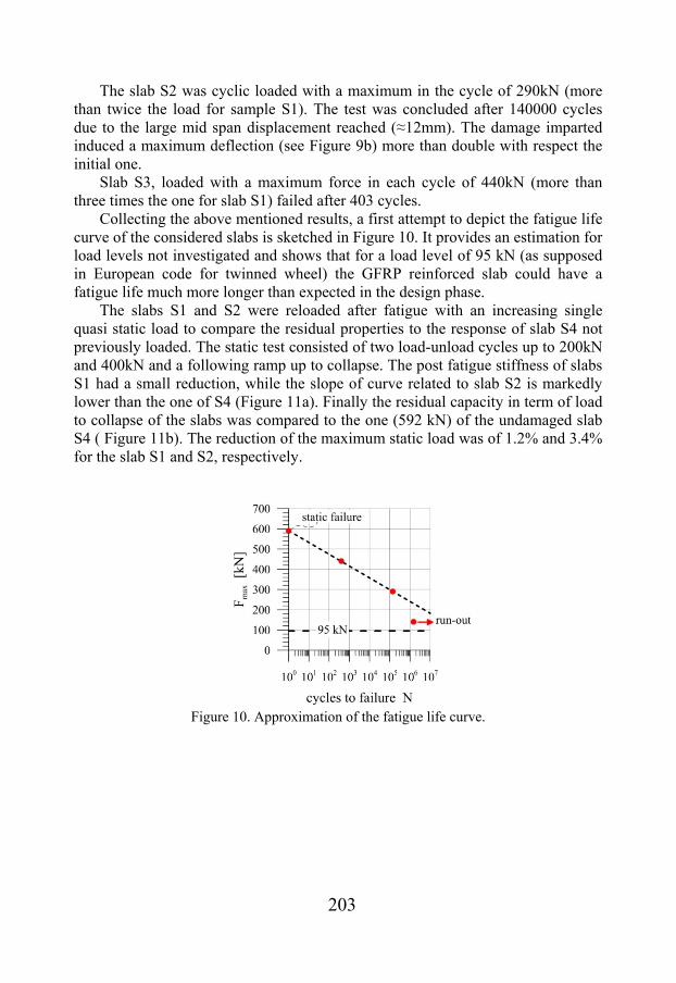
The slab S2 was cyclic loaded with a maximum in the cycle of 290kN (more than twice the load for sample S1). The test was concluded after 140000 cycles due to the large mid span displacement reached (≈12mm). The damage imparted induced a maximum deflection (see Figure 9b) more than double with respect the initial one.
Slab S3, loaded with a maximum force in each cycle of 440kN (more than three times the one for slab S1) failed after 403 cycles.
Collecting the above mentioned results, a first attempt to depict the fatigue life curve of the considered slabs is sketched in Figure 10. It provides an estimation for load levels not investigated and shows that for a load level of 95 kN (as supposed in European code for twinned wheel) the GFRP reinforced slab could have a fatigue life much more longer than expected in the design phase.
The slabs S1 and S2 were reloaded after fatigue with an increasing single quasi static load to compare the residual properties to the response of slab S4 not previously loaded. The static test consisted of two load-unload cycles up to 200kN and 400kN and a following ramp up to collapse. The post fatigue stiffness of slabs S1 had a small reduction, while the slope of curve related to slab S2 is markedly lower than the one of S4 (Figure 11a). Finally the residual capacity in term of load to collapse of the slabs was compared to the one (592 kN) of the undamaged slab S4 ( Figure 11b). The reduction of the maximum static load was of 1.2% and 3.4% for the slab S1 and S2, respectively.
Figure 10. Approximation of the fatigue life curve.

204
(a) (b) Figure 11. Static tests: load vs. displacement of (a) LVDT2 and (b) jack.
5. EFFECT OF ELEVATED TEMPERATURE ON GFRP REINFORCED
BEAMS GFRP presents poor resistance to elevated temperature due to the low value of the glass transition temperature of the polymeric matrix that can be even close to 80 °C. A temperature of this level is higher than the thermal loads due to seasonal changes and solar radiation (Priestley, 1989), but could be easily overcome during fire exposure. For example, a bridge deck may be interested by different types of fire. A vehicle burning on a bridge deck cannot damage the GFRP rebars because they are under the source of heating, and are protected by asphalt concrete and concrete cover. The case of fire under the bridge is much more dangerous both for strength and durability of the bridge deck. A distinction is needed in this case: when dealing with maximum temperatures higher than 600 °C the real problem is the rapid strength decrease of the structure, independently of the type of rebar adopted (see e.g. Sadek et al, 2007). On the contrary, when the maximum sustained temperature does not exceed approximately 600 °C concrete strength does not tremendously decrease (Di Luzio et al, 2013), whereas bond between GFRP rebars and concrete vanishes.
The experimental tests here considered are described in details in (Carvelli et al, 2013). They deal with narrow strips of a bridge slab (see above and Carvelli et al, 2010) reinforced with four different schemes of GFRP rebars. A series of specimens (0.5 m wide, 2.5 m long and 0.2 m thick) were tested both at room temperature and after heating up to 550 °C.
The concrete beams were reinforced with unidirectional E-glass fibre reinforced/vynilester (GFRP) having nominal diameter of 16 mm. The external surface of the rebars has a spiral wound yarn along the length and quartz sand to increase bond to concrete. The mechanical properties of the rebars were experimentally measured (see Carvelli et al, 2009). At room temperature, the GFRP bars have longitudinal tensile strength of 885 MPa and tensile modulus of 39 GPa. The mechanical properties of concrete at room temperature are:

205
cylindrical compression strength of 49.8 MPa; tensile strength of 4 MPa measured by indirect tensile tests (EN 12390-6). The degradation of the mechanical properties after heating for 2 h at 550 °C was measured (see Carvelli et al, 2013). The cylindrical compression strength decreased to 23.3 MPa, while the residual tensile strength was 1.1 MPa.
The beams were heated up to 550°C on a portion of the bottom surface of 48×50 cm (see grey shaded rectangles in Figure 12a) of the unloaded specimen. The temperature was continuously recorded during heating in three different positions of the heated zone (see Figure 12b): in the centre of the heated area and on both longitudinal edge sides, 2 cm inside the concrete; all positions being located 3 cm from the bottom to monitor the temperature close to the GFRP rebars.
The maximum temperature recorded close to the GFRP rebars was about 400 °C. This temperature allows neglecting the expansion of the quartz sand consequence of the reversible change in crystal structure of the quartz (from - to -quartz). After heating for more than 2 h, the specimens were subjected to three point bending quasi-static loading with load applied on a contact surface of 30×20cm (see Figure 12b).
The experimental tests were then modelled according to both an analytical and finite element approach (see more details in Pagani et al, 2014).
The proposed analytical formulation, modelling the thermomechanical behaviour of the concrete strip reinforced with GFRP bars, is based on the following assumptions: • temperature distribution previously derived by proper thermal analysis; • linear elastic behaviour of GFRP and elasto-plastic for concrete; • planarity of the cross-section after bending throughout fire exposure; • perfect bond between concrete and GFRP rebars.
(a)

206
(b)
Figure 12. a) Beam geometry and scheme of the continuous reinforcement; (b) experimental setup with thermocouples (TC) and displacement transducers (LVDT)
position.
In relation to the last assumption, it is a matter of fact that deterioration of the mechanical properties of GFRP (especially strength and Young’s modulus), as well as the bond properties, starts when temperature reaches values close to the glass transition temperature (Palmieri et al, 2012), that is between 70 °C and 180 °C depending on the type of resin. Nevertheless, both decrease of Young’s modulus and bond properties of the rebars are globally taken into account by means of a reduction of Young’s modulus, consistently to the simplified method suggested in Nigro et al, 2014.
Two non-linear coupled thermo-mechanical finite element models were developed using the commercial code ABAQUS to simulate the GFRP reinforced beam bending behaviour after local heating, namely plane stress (2D) and three dimensional (3D).
The initial temperature was set equal to the room temperature. The experimental temperature history was imposed as a prescribed boundary condition on the heated portion of the bottom edge of the model: the temperature increases from 20 to 550 °C in 60 min and then remained constant for 90 min (see GFRP bar after heating and loading in Figure 13b). The heat transfer problem is nonlinear being the material properties temperature dependent. At elevated temperatures, chemically bounded water on concrete is released gradually as free water and begins to evaporate. During this process, additional heat is absorbed by the concrete, which affects the temperature development in concrete. Instead of conducting a complex coupled thermo-hydro-mechanical analysis, the concrete specific heat Cp(T) was assumed to be temperature dependent to reflect this influence in the heat transfer analysis, according to EN 1992-1-2. Both concrete density and thermal conductivity were assumed to decrease with temperature according to EN 1992-1-2. GFRP thermal properties were assumed to be constant. In particular, the density was taken equal to 1900 kg/m3, while thermal
207
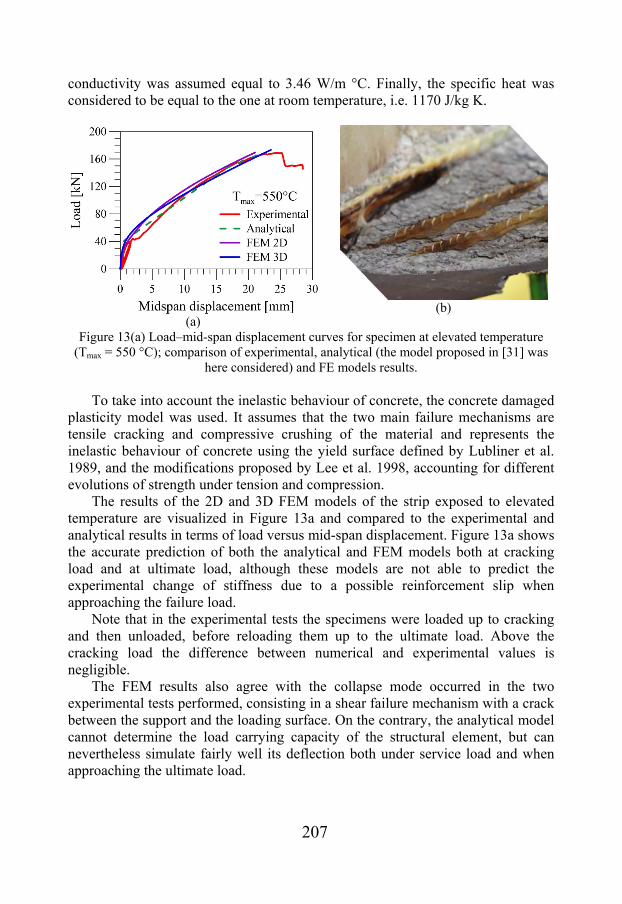
conductivity was assumed equal to 3.46 W/m °C. Finally, the specific heat was considered to be equal to the one at room temperature, i.e. 1170 J/kg K.
(a)
(b)
Figure 13(a) Load–mid-span displacement curves for specimen at elevated temperature (Tmax = 550 °C); comparison of experimental, analytical (the model proposed in [31] was
here considered) and FE models results.
To take into account the inelastic behaviour of concrete, the concrete damaged plasticity model was used. It assumes that the two main failure mechanisms are tensile cracking and compressive crushing of the material and represents the inelastic behaviour of concrete using the yield surface defined by Lubliner et al. 1989, and the modifications proposed by Lee et al. 1998, accounting for different evolutions of strength under tension and compression.
The results of the 2D and 3D FEM models of the strip exposed to elevated temperature are visualized in Figure 13a and compared to the experimental and analytical results in terms of load versus mid-span displacement. Figure 13a shows the accurate prediction of both the analytical and FEM models both at cracking load and at ultimate load, although these models are not able to predict the experimental change of stiffness due to a possible reinforcement slip when approaching the failure load.
Note that in the experimental tests the specimens were loaded up to cracking and then unloaded, before reloading them up to the ultimate load. Above the cracking load the difference between numerical and experimental values is negligible.
The FEM results also agree with the collapse mode occurred in the two experimental tests performed, consisting in a shear failure mechanism with a crack between the support and the loading surface. On the contrary, the analytical model cannot determine the load carrying capacity of the structural element, but can nevertheless simulate fairly well its deflection both under service load and when approaching the ultimate load.

208
6. CONCLUSIONS The activities developed at Politecnico di Milano dealing with the use of GFRP rebars for the internal reinforcement of concrete structural elements were presented.
The problems related to the determination of the mechanical properties of the GFRP rebars were discussed.
The wide experimental campaign made to test the bond behaviour of GFRP rebars embedded in concrete was presented. Pull-out tests were performed on helically wrapped and sand coated GFRP rebars with several different diameters. The development length of FRP bars may be determined on the basis of the expressions suggested in some design codes that are examined in the paper. The experimental results of the pull-out tests were compared with the proposal of some guidelines.The main outcomes concerning the current codes are the following:
(a) in all the design formulae the development length is always influenced by the concrete compressive strength, although debonding of some GFRP rebars often does not depend on this parameter;
b) the bond strength is a function of the ratio between the concrete cover and the bar diameter irrespectively of the failure mode.
Another research carried out at the Politecnico of Milan regards the durability of concrete bridge decks with GFRP rebars. The experimental investigation, here briefly presented, aimed to understand the mechanical behaviour under cyclic (moving) loading of full scale bridge slab prototypes reinforced with GFRP bars and to verify the accuracy of the rules suggested by the European Codes for these bridge deck slabs.
Finally, the results of experiments aiming to evaluate the effects of high temperatures on concrete beams were presented. The collapse mode consisted in a shear failure mechanism with a crack between the support and the loading surface. The finite elements models could predict this behaviour with good accuracy. On the contrary, the analytical model cannot determine the load carrying capacity of the structural element, but can nevertheless simulate fairly well its deflection both under service load and when approaching the ultimate load.
All these researches suggest that GFRP rebars are effective in substituting steel rebars in concrete bridge slabs, although their elastic-brittle behaviour prevents from their generalized adoption in common practice.

209
REFERENCES
[1] ABAQUS/Standard, 2007. Theory and users manuals, release 6.10-1. Pawtucket, RI, USA: HKS Inc.
[2] ACI 440.1R, 2006. American Concrete Institute. Guide for the design and construction of structural concrete reinforced with FRP Bars. ACI, Farmington Hills, Mich.
[3] ACI 440.3R, 2004. American Concrete Institute. Guide test methods for fiber-reinforced polymers (FRPs) for reinforcing or strengthening concrete structures. ACI, Farmington Hills, Mich.
[4] ASTM D7205M, 2006. American Society for Testing and Materials. Standard test method for tensile properties of fiber reinforced polymer matrix composite bars. ASTM, West Conshohocken, PA.
[5] Baena M., Torres L., Turon A., Barris C. (2009). “Experimental study of bond behaviour between concrete and FRP bars using a pull-out test”. Composites: Part B, 40 (8): 784–797.
[6] Bakis C.E., Bank L.C., Brown V.L., Cosenza E., Davalos J.F., Lesko J.J., Machida A., Rizkalla S. H., and Triantafillou, T. C. (2002). “Fibre-reinforced polymer composites for construction-state-of-the-art review”. ASCE Journal of Composites for Construction, 6(2), 73-87.
[7] Carvelli V., Fava G., Pisani M.A. (2009). “Anchor system for tension testing of large diameter GFRP bars”. ASCE Journal of Composites for Construction, 13(5), 344-349.
[9] Carvelli V., Pisani M.A., Poggi C. (2010). “Fatigue behaviour of concrete bridge deck slabs reinforced with GFRP bars”. Composites: Part B, 41(7), 560-567.
[10] Carvelli V., Pisani M.A., Poggi C. (2013). “High temperature effects on concrete members reinforced with GFRP rebars”. Composites: Part B, 54, 125-32.
[11] CNR-DT 203, 2006. Italian National Research Council (CNR) (2006). Guide for the design and construction of concrete structures reinforced with fiber-reinforced polymer bars. CNR, Rome, Italy.
[12] Daniel I. M. and Ishai O. (1994). Engineering mechanics of composite materials, Oxford University Press, New York
[13] Di Luzio G. and Biolzi L. (2013). “Assessing the residual fracture properties of thermally damaged high strength concrete”. Mech Mater, 4, 27-43
[14] El-Ragaby A., El-Salakawy E., Benmokrane B. (2007). “Fatigue analysis of concrete bridge deck slabs reinforced with E-glass/Vynil ester FRP reinforcing bars”. Composites: Part B, 38, 703-711.
[15] EN 10080, 2005. Steel for the reinforcement of concrete - Weldable reinforcing steel - General. European Committee for Standardization, CEN Management Centre, Brussels, Belgium.
[16] EN 1991-2:2005. Eurocode 1 - Actions on structures - Part 2: Traffic loads on bridges. European Committe for Standardization, CEN Management Centre, Brussels, Belgium.
[17] EN 1992-2, 2006. Eurocode 2 - Design of concrete structures – Part 2: Concrete bridges. Design and detailing rules. European Committe for Standardization, CEN Management Centre, Brussels, Belgium.

210
[18] EN 1992-1-2, 2005. Eurocode 2 - Design of concrete structures – Part 1–2: General rules – structural fire design. European Committe for Standardization, CEN Management Centre, Brussels, Belgium.
[19] EN 12390-6, 2000. Tensile splitting strength of test specimens. European committee for standardization, CEN Management Centre, Brussels, Belgium
[20] Fava, G., Carvelli, V., Pisani, M.A. (2012). “Mechanical behaviour modelling of a new anchor system for large diameter GFRP bars”. Composites Part B, 43(3), 1397-1404.
[21] fib bulletin 40, 2007. International Federation of Concrete (fib). FRP reinforcement in RC structures. Lausanne.
[22] Hejlla A., Täljstena B., Motavalli M. (2006). “Static and fatigue investigation of second generation steel-free bridge decks”. Cement & Concrete Composites, 28, 890-897.
[23] ISO TC 71/SC 6/WG. International Standards Organization (ISO) (2003). Non-conventional reinforcement of concrete – Test methods – Part 1: Fiber reinforced polymer (FRP) bars and grids. Geneva, Switzerland.
[24] JSCE, 1997. Japan Society of Civil Engineers. Recommendation for design and construction of concrete structures using continuous fiber reinforcing materials. Concrete Engineering Series No. 23
[25] Lee J., Fenves G.L. (1998). “Plastic-damage model for cyclic loading of concrete structures”. J Eng Mech, 124, 892-900-
[26] Lubliner J., Oliver J., Oller S., Oñate E. (1989). “A plastic-damage model for concrete”. Int J Solids Struct, 25, 299-326.
[27] Mufti A.A. and Neale K.W. (2008). “State-of-the-art of FRP and SHM applications in bridge structures in Canada”. Composites Rresearch Journal, 2(2), 60-69.
[28] Nigro E., Cefarelli G., Bilotta A., Manfredi G., Cosenza E. (2014). “Guidelines for flexural resistance of FRP reinforced concrete slabs and beams in fire”. Composites: Part B, 58, 103–112.
[29] Pagani R., Bocciarelli M., Carvelli V., Pisani M.A. (2014). “Modelling high temperature effects on bridge slabs reinforced with GFRP rebars”. Engineering Structures, 81, 318-326.
[30] Palmieri A., Matthys S., Taerwe L. (2012). “Experimental investigation on fire endurance of insulated concrete beams strengthened with near surface mounted FRP bar reinforcement”. Composites Part B, 43(3), 885–95.
[31] Pardikaris P.C., Beim S. (1988). “RC Bridges under pulsating and moving load”. ASCE Journal of Structural Engineering, 114(3), 591-607.
[32] Pendhari S.S., Kant T. and Desai Y.M. (2008). “Application of polymer composites in civil construction: a general review”. Composite Structures, 84, 114-24
[33] Priestley M.J.N. (1987). “The thermal response of concrete bridges, in concrete bridges engineering: performance and advances”. London: Elsevier Applied Science, 143-188.
[34] Rostàsy F.S. (1993). “FRP tensile elements for prestressed concrete: state of the art, potentials and limits”. In: Nanni A, Dolan CW, editors. “Fiber-reinforced plastic reinforcement for concrete structures”, SP-138, American Concrete Institute, Farmington Hills, Mich, 347–365.
[35] Sadek A.W., El-Hawary M.M., El-Dieb A.S. (2007). “Fire resistance testing of concrete slabs reinforced by GFRP rebars. J. Appl Fire Sci, 15, 131-145.