getting started with m.2 modules and i.mx 6/7/8 · the first step address basic steps like powering...
TRANSCRIPT

Getting Started with M.2 Modules and i.MX 6/7/8
Copyright 2019 © Embedded Artists AB
Getting Started with M.2 Modules and i.MX 6/7/8

Getting Started with M.2 Modules and i.MX 6/7/8 Page 2
Copyright 2019 © Embedded Artists AB Rev A
Embedded Artists AB Jörgen Ankersgatan 12 SE-211 45 Malmö Sweden
http://www.EmbeddedArtists.com
Copyright 2019 © Embedded Artists AB. All rights reserved.
No part of this publication may be reproduced, transmitted, transcribed, stored in a retrieval system, or translated into any language or computer language, in any form or by any means, electronic, mechanical, magnetic, optical, chemical, manual or otherwise, without the prior written permission of Embedded Artists AB.
Disclaimer
Embedded Artists AB makes no representation or warranties with respect to the contents hereof and specifically disclaim any implied warranties or merchantability or fitness for any particular purpose. Information in this publication is subject to change without notice and does not represent a commitment on the part of Embedded Artists AB.
Feedback
We appreciate any feedback you may have for improvements on this document. Send your comments by using the contact form: www.embeddedartists.com/contact.
Trademarks
All brand and product names mentioned herein are trademarks, services marks, registered trademarks, or registered service marks of their respective owners and should be treated as such.
Getting Started with M.2 Modules and i.MX 6/7/8 Page 3
Copyright 2019 © Embedded Artists AB Rev A
Table of Contents 1 Document Revision History ................................. 5
2 Introduction ........................................................... 6
2.1 Conventions .................................................................................... 6
3 QuickStart Guide ................................................... 7
3.1 Follow "Getting Started" Guide ..................................................... 7
3.2 Mount M.2 Module .......................................................................... 7
3.3 Power-up Board .............................................................................. 9
3.4 Linux Console - Manually Setup Wi-Fi Interface from Console 10
3.5 Access and Configure Bluetooth Devices ................................. 13
3.5.1 Additional Links ........................................................................... 15
3.6 Wi-Fi: iperf3 Test .......................................................................... 16
3.7 Wi-Fi: Check the Linux Boot Log ................................................ 17
3.8 Wi-Fi: Connect Automatically During Boot ................................ 17
3.8.1 Shortcut ....................................................................................... 18
3.9 Bluetooth: keyboard .................................................................... 19
4 COM Carrier Board V2 Advanced Features ...... 22
4.1 VBAT Current Measurement ........................................................ 22
4.2 VBAT 3.3V or 3.6V ........................................................................ 23
4.3 Support for 3.3V IO logic level (if M.2 module supports it) ....... 23
4.4 Bluetooth UART Interception ...................................................... 23
4.5 Dual UART Debug Channels and JTAG...................................... 25
4.6 Audio Codec Multiplexing ........................................................... 25
5 Software Update .................................................. 26
5.1 Linux Host Setup .......................................................................... 26
5.1.1 Introduction .................................................................................. 26
5.1.2 Required Packages ..................................................................... 26
5.1.3 Install the repo tool ..................................................................... 26
5.1.4 Download Yocto recipes .............................................................. 27
5.2 Building Images ............................................................................ 27
5.2.1 Available Images ......................................................................... 27
5.2.2 Machine Configurations ............................................................... 28
5.2.3 Initialize Build .............................................................................. 28
5.2.4 Starting the Build ......................................................................... 29
5.3 Deploying Images ......................................................................... 29
5.3.1 Manufacturing Tool ...................................................................... 29 5.3.1.1 Download the Tool ................................................................................ 29 5.3.1.2 Prepare hardware ................................................................................. 30 5.3.1.3 OTG boot mode – J2 jumper ................................................................. 30 5.3.1.4 Configurations ....................................................................................... 30 5.3.1.5 Download Your Own Images ................................................................. 31
Getting Started with M.2 Modules and i.MX 6/7/8 Page 4
Copyright 2019 © Embedded Artists AB Rev A
5.3.1.6 Run the Tool ......................................................................................... 31
5.3.2 UUU ............................................................................................ 31 5.3.2.1 Download the Tool ................................................................................ 32 5.3.2.2 Prepare hardware ................................................................................. 32 5.3.2.3 OTG boot mode – J2 jumper ................................................................. 32 5.3.2.4 Configurations ....................................................................................... 32 5.3.2.5 Download Your Own Images ................................................................. 33 5.3.2.6 Run the Tool in Ubuntu ......................................................................... 33 5.3.2.7 Run the Tool in Windows....................................................................... 33 5.3.2.8 Troubleshoot ......................................................................................... 34
5.4 Building without Yocto ................................................................ 36
5.4.1 Stand-alone Toolchain ................................................................ 36
5.4.2 Build Linux kernel from source code ........................................... 36
5.4.3 Build u-boot from source code ..................................................... 37
5.5 NVRAM .......................................................................................... 38
5.6 Firmware ....................................................................................... 38
5.7 WinSCP ......................................................................................... 38
5.7.1 Download and Install ................................................................... 38
5.7.2 Connect to Target ........................................................................ 38
5.7.3 Copy Files ................................................................................... 41
Getting Started with M.2 Modules and i.MX 6/7/8 Page 5
Copyright 2019 © Embedded Artists AB Rev A
1 Document Revision History Revision Date Description
PA2 2019-03-11 First release.
PA3 2019-03-14 Added description about how to build the Linux kernel (chapter 5).
PA4 2019-03-29 Added Software Update section. Fixed review comments. Added shortcut description in 3.8.1
PA5 2019-04-01 Added information about CyBluetool to section 4.4
PA6 2019-04-01 Updated information about CyBluetool to section 4.4
PA7 2019-04-12 Added pictures of how to mount an M.2 module.
PA8 2019-05-08 Added information about i.MX8, uuu and a section about WinSCP
Getting Started with M.2 Modules and i.MX 6/7/8 Page 6
Copyright 2019 © Embedded Artists AB Rev A
2 Introduction This document describes how to add wireless functionality with M.2 modules to an iMX Developer’s Kit V2. Linux commands for controlling wireless functionality are also presented.
There are several different iMX Developer’s Kits V2 and this document refers to all of these kits collectively as iMX Developer’s Kits. Please note that all available iMX Developer’s Kits may not support all the presented wireless technologies or more specifically the interface used to communicate with a hardware module. The PCIe interface is for example not supported by all i.MX processors.
All interfaces, needed tools and kernel configurations described in this document have been added / enabled in the prepared images available at http://imx.embeddedartists.com/. To make changes to your own build, see the iMX Working with Yocto document which can be downloaded on each COM board’s product page.
Additional documentation you might need is.
The Getting Started document for the iMX Developer's Kit you are using
COM Board Datasheet for the specific COM board you are using
COM Carrier Board Datasheet
M.2 Module Datasheet for the specific M.2 module you are using
2.1 Conventions
A number of conventions have been used throughout to help the reader better understand the content of the document.
Constant width text – is used for file system paths and command, utility and tool names.
$ This field illustrates user input in a terminal running on the
development workstation, i.e., on the workstation where you edit,
configure and build Linux
# This field illustrates user input on the target hardware, i.e.,
input given to the terminal attached to the COM Board
TThhiiss ffiieelldd iiss uusseedd ttoo iilllluussttrraattee eexxaammppllee ccooddee oorr eexxcceerrpptt ffrroomm aa
ddooccuummeenntt..
This field is used to highlight important information

Getting Started with M.2 Modules and i.MX 6/7/8 Page 7
Copyright 2019 © Embedded Artists AB Rev A
3 QuickStart Guide This chapter is a step-by-step guide to get Wi-Fi and Bluetooth connections up in shortest possible time:
1. The first step address basic steps like powering the board and getting access to the console.
2. The second step describes where and how to physically mount the M.2 module.
3. The third step describes how to power up the system and boot with correct setting (given the M.2 module that is mounted).
4. The fourth step describe how to manually setup the Wi-Fi interface from the Linux console.
5. The fifth step describe how to access and configure the Bluetooth interface.
Above are the five simple steps to get up-and-running immediately!
There are a couple of more sections describing different aspects, like performance measurements with iperf and how to connect specific Bluetooth devices, like a keyboard.
3.1 Follow "Getting Started" Guide
Follow the instructions in the getting started guide https://www.embeddedartists.com/getting-started-with-imx-developers-kit-v2/ to get access to the console and to connect the power supply but keep the board powered off for now.
3.2 Mount M.2 Module
Make sure the iMX Developer's Kit is powered off and then mount the M.2 Module, as illustrated in the picture below:
Figure 1 – M.2 Module on COM Carrier Board V2
Getting Started with M.2 Modules and i.MX 6/7/8 Page 8
Copyright 2019 © Embedded Artists AB Rev A
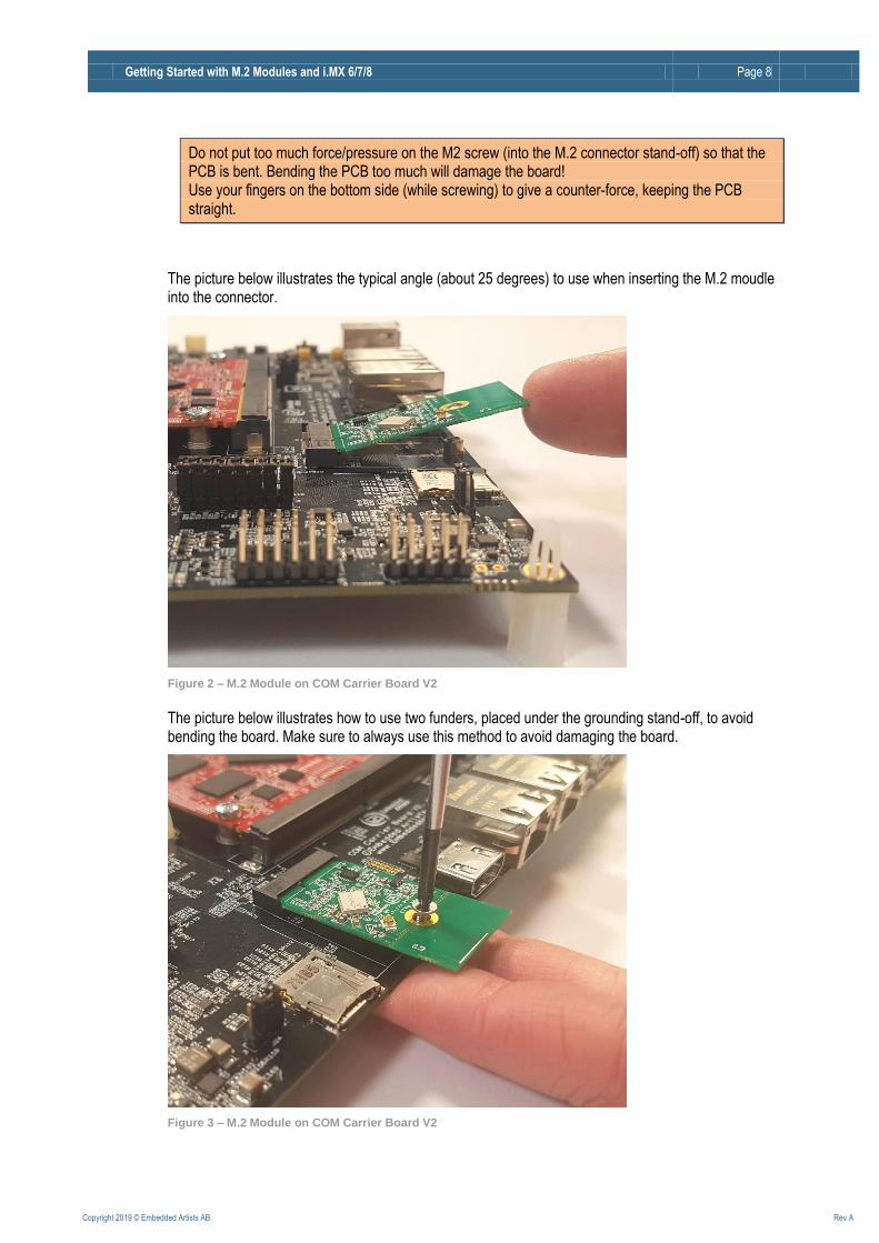
Do not put too much force/pressure on the M2 screw (into the M.2 connector stand-off) so that the PCB is bent. Bending the PCB too much will damage the board! Use your fingers on the bottom side (while screwing) to give a counter-force, keeping the PCB straight.
The picture below illustrates the typical angle (about 25 degrees) to use when inserting the M.2 moudle into the connector.
Figure 2 – M.2 Module on COM Carrier Board V2
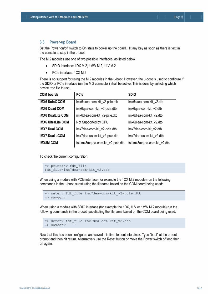
The picture below illustrates how to use two funders, placed under the grounding stand-off, to avoid bending the board. Make sure to always use this method to avoid damaging the board.
Figure 3 – M.2 Module on COM Carrier Board V2
Getting Started with M.2 Modules and i.MX 6/7/8 Page 9
Copyright 2019 © Embedded Artists AB Rev A
3.3 Power-up Board
Set the Power on/off switch to On state to power up the board. Hit any key as soon as there is text in the console to stop in the u-boot.
The M.2 modules use one of two possible interfaces, as listed below
SDIO interface: 1DX M.2, 1MW M.2, 1LV M.2
PCIe interface: 1CX M.2
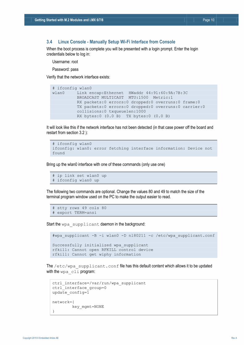
There is no support for using the M.2 modules in the u-boot. However, the u-boot is used to configure if the SDIO or PCIe interface (on the M.2 connector) shall be active. This is done by selecting which device tree file to use.
COM boards PCIe SDIO
iMX6 SoloX COM imx6sxea-com-kit_v2-pcie.dtb imx6sxea-com-kit_v2.dtb
iMX6 Quad COM imx6qea-com-kit_v2-pcie.dtb imx6qea-com-kit_v2.dtb
iMX6 DualLite COM imx6dlea-com-kit_v2-pcie.dtb imx6dlea-com-kit_v2.dtb
iMX6 UltraLite COM Not Supported by CPU imx6ulea-com-kit_v2.dtb
iMX7 Dual COM imx7dea-com-kit_v2-pcie.dtb imx7dea-com-kit_v2.dtb
iMX7 Dual uCOM imx7dea-ucom-kit_v2-pcie.dtb imx7dea-ucom-kit_v2.dtb
iMX8M COM fsl-imx8mq-ea-com-kit_v2-pcie.dts fsl-imx8mq-ea-com-kit_v2.dts
To check the current configuration:
=> printenv fdt_file
fdt_file=imx7dea-com-kit_v2.dtb
When using a module with PCIe interface (for example the 1CX M.2 module) run the following commands in the u-boot, substituting the filename based on the COM board being used:
=> setenv fdt_file imx7dea-com-kit_v2-pcie.dtb
=> saveenv
When using a module with SDIO interface (for example the 1DX, 1LV or 1MW M.2 module) run the following commands in the u-boot, substituting the filename based on the COM board being used:
=> setenv fdt_file imx7dea-com-kit_v2.dtb
=> saveenv
Now that this has been configured and saved it is time to boot into Linux. Type "boot" at the u-boot prompt and then hit return. Alternatively use the Reset button or move the Power switch off and then on again.
Getting Started with M.2 Modules and i.MX 6/7/8 Page 10
Copyright 2019 © Embedded Artists AB Rev A
3.4 Linux Console - Manually Setup Wi-Fi Interface from Console
When the boot process is complete you will be presented with a login prompt. Enter the login credentials below to log in:
Username: root
Password: pass
Verify that the network interface exists:
# ifconfig wlan0
wlan0 Link encap:Ethernet HWaddr 44:91:60:9A:7B:3C
BROADCAST MULTICAST MTU:1500 Metric:1
RX packets:0 errors:0 dropped:0 overruns:0 frame:0
TX packets:0 errors:0 dropped:0 overruns:0 carrier:0
collisions:0 txqueuelen:1000
RX bytes:0 (0.0 B) TX bytes:0 (0.0 B)
It will look like this if the network interface has not been detected (in that case power off the board and restart from section 3.2 ):
# ifconfig wlan0
ifconfig: wlan0: error fetching interface information: Device not
found
Bring up the wlan0 interface with one of these commands (only use one)
# ip link set wlan0 up
# ifconfig wlan0 up
The following two commands are optional. Change the values 80 and 49 to match the size of the terminal program window used on the PC to make the output easier to read.
# stty rows 49 cols 80
# export TERM=ansi
Start the wpa_supplicant daemon in the background:
#wpa_supplicant -B -i wlan0 -D nl80211 -c /etc/wpa_supplicant.conf
Successfully initialized wpa_supplicant
rfkill: Cannot open RFKILL control device
rfkill: Cannot get wiphy information
The /etc/wpa_supplicant.conf file has this default content which allows it to be updated
with the wpa_cli program:
ccttrrll__iinntteerrffaaccee==//vvaarr//rruunn//wwppaa__ssuupppplliiccaanntt
ccttrrll__iinntteerrffaaccee__ggrroouupp==00
uuppddaattee__ccoonnffiigg==11
nneettwwoorrkk=={{
kkeeyy__mmggmmtt==NNOONNEE
}}

Getting Started with M.2 Modules and i.MX 6/7/8 Page 11
Copyright 2019 © Embedded Artists AB Rev A
It is now time to run the interactive wpa_cli tool to scan for, select and then connect to a network.
# wpa_cli -i wlan0
Scan for networks (press ENTER after the last line below to get back to the prompt):
> scan
OK
<3>CTRL-EVENT-SCAN-STARTED
<3>CTRL-EVENT-SCAN-RESULTS
To list found networks:
> scan_result
bssid / frequency / signal level / flags / ssid
00:1e:00:00:ca:89 2412 -62 [WPA2-PSK-CCMP+TKIP][ESS] EA Guest
00:fa:00:00:49:ff 5500 -86 [WPA2-EAP-CCMP][ESS] BOB
00:c7:00:00:b2:80 2462 -86 [WPA2-EAP-CCMP][ESS] ALICE
00:fa:00:00:49:f1 2412 -76 [ESS] Company_Guest
00:c7:00:00:b3:90 2412 -93 [WPA2-EAP-CCMP][ESS] Company Inc
The list shows that the “EA Guest” network uses pre-shared keys (PSK) as authentication. It is a relatively low security alternative but it is simple to use. The following example will connect to that network using the password “welcome”. For examples using other authentication methods see https://wiki.netbsd.org/tutorials/how_to_use_wpa_supplicant/.
To connect to the “EA Guest” network:
> remove_network all Optional
OK
> add_network
0
> set_network 0 ssid "EA Guest"
OK
> set_network 0 psk "welcome"
OK
> enable_network 0
...
<3>CTRL-EVENT-CONNECTED...
> status
bssid=00:1e:00:00:ca:89
ssid=EA Guest
id=0
mode=station
pairwise_cipher=CCMP
group_cipher=TKIP
key_mgmt=WPA2-PSK
wpa_state=COMPLETED
address=d8:00:93:00:1e:00
...
> save_config Very important to save before quitting
OK
> quit
Note: If there is more than one network (added before or added automatically) the add_network
call will return another number, for example 1. Use that in the set_network and
Getting Started with M.2 Modules and i.MX 6/7/8 Page 12
Copyright 2019 © Embedded Artists AB Rev A
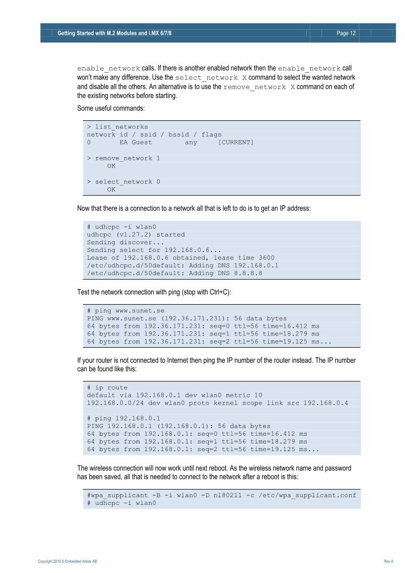
enable_network calls. If there is another enabled network then the enable_network call
won’t make any difference. Use the select_network X command to select the wanted network
and disable all the others. An alternative is to use the remove_network X command on each of
the existing networks before starting.
Some useful commands:
> list_networks
network id / ssid / bssid / flags
0 EA Guest any [CURRENT]
> remove_network 1
OK
> select_network 0
OK
Now that there is a connection to a network all that is left to do is to get an IP address:
# udhcpc -i wlan0
udhcpc (v1.27.2) started
Sending discover...
Sending select for 192.168.0.6...
Lease of 192.168.0.6 obtained, lease time 3600
/etc/udhcpc.d/50default: Adding DNS 192.168.0.1
/etc/udhcpc.d/50default: Adding DNS 8.8.8.8
Test the network connection with ping (stop with Ctrl+C):
# ping www.sunet.se
PING www.sunet.se (192.36.171.231): 56 data bytes
64 bytes from 192.36.171.231: seq=0 ttl=56 time=16.412 ms
64 bytes from 192.36.171.231: seq=1 ttl=56 time=18.279 ms
64 bytes from 192.36.171.231: seq=2 ttl=56 time=19.125 ms...
If your router is not connected to Internet then ping the IP number of the router instead. The IP number can be found like this:
# ip route
default via 192.168.0.1 dev wlan0 metric 10
192.168.0.0/24 dev wlan0 proto kernel scope link src 192.168.0.4
# ping 192.168.0.1
PING 192.168.0.1 (192.168.0.1): 56 data bytes
64 bytes from 192.168.0.1: seq=0 ttl=56 time=16.412 ms
64 bytes from 192.168.0.1: seq=1 ttl=56 time=18.279 ms
64 bytes from 192.168.0.1: seq=2 ttl=56 time=19.125 ms...
The wireless connection will now work until next reboot. As the wireless network name and password has been saved, all that is needed to connect to the network after a reboot is this:
#wpa_supplicant -B -i wlan0 -D nl80211 -c /etc/wpa_supplicant.conf
# udhcpc -i wlan0

Getting Started with M.2 Modules and i.MX 6/7/8 Page 13
Copyright 2019 © Embedded Artists AB Rev A
There are several ways to see the status of your connection and the network it is connection to. Here are two examples (not showing the output):
# iw dev wlan0 link
# wl assoc
3.5 Access and Configure Bluetooth Devices
The Bluetooth device uses the UART interface and which interface it is depends on the COM Board as shown in this table.
COM boards Bluetooth UART
iMX6 SoloX COM /dev/ttymxc1
iMX6 Quad COM /dev/ttymxc4
iMX6 DualLite COM /dev/ttymxc4
iMX6 UltraLite COM /dev/ttymxc1
iMX7 Dual COM /dev/ttymxc1
iMX7 Dual uCOM /dev/ttymxc1
iMX8M COM /dev/ttymxc1
Start by initializing the UART (pick the UART in the table above according to you COM board):
# hciattach /dev/ttymxc1 bcm43xx 3000000 flow -t 20
bcm43xx_init
Set Controller UART speed to 3000000 bit/s
Flash firmware /etc/firmware/BCM43012C0.1LV.hcd
Set Controller UART speed to 3000000 bit/s
Setting TTY to N_HCI line discipline
Device setup complete
The output from the hciattach command will show the module name (in the case above a 1LV M.2 module was used). If the M.2 module is not inserted or it cannot be communicated with then the hciattach command will timeout after 20 seconds.
Check if the device is up:
# hciconfig -a hci0
hci0: Type: Primary Bus: UART
BD Address: 44:91:60:9A:62:14 ACL MTU: 1021:8 SCO MTU:
64:1
DOWN
RX bytes:708 acl:0 sco:0 events:38 errors:0
TX bytes:446 acl:0 sco:0 commands:38 errors:0
Features: 0xbf 0xfe 0xcf 0xfe 0xdb 0xff 0x7b 0x87
Packet type: DM1 DM3 DM5 DH1 DH3 DH5 HV1 HV2 HV3
Link policy: RSWITCH SNIFF
Link mode: SLAVE ACCEPT
If it is down then bring it up with:
Getting Started with M.2 Modules and i.MX 6/7/8 Page 14
Copyright 2019 © Embedded Artists AB Rev A
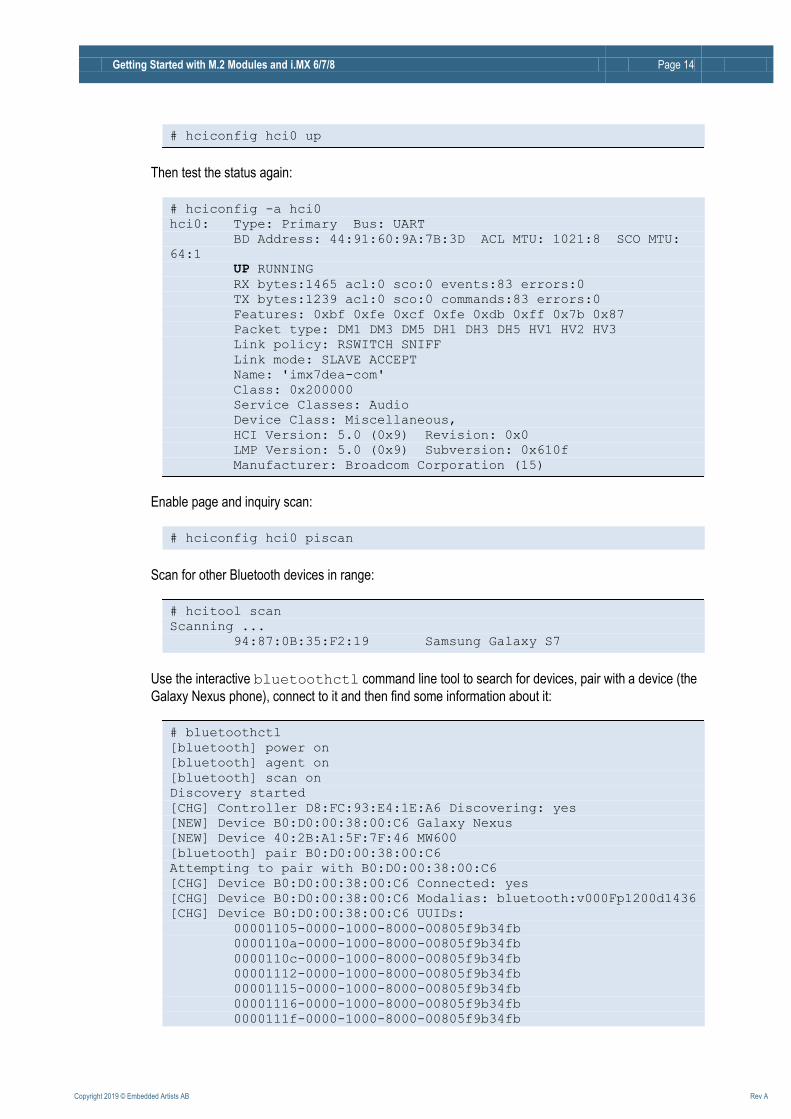
# hciconfig hci0 up
Then test the status again:
# hciconfig -a hci0
hci0: Type: Primary Bus: UART
BD Address: 44:91:60:9A:7B:3D ACL MTU: 1021:8 SCO MTU:
64:1
UP RUNNING
RX bytes:1465 acl:0 sco:0 events:83 errors:0
TX bytes:1239 acl:0 sco:0 commands:83 errors:0
Features: 0xbf 0xfe 0xcf 0xfe 0xdb 0xff 0x7b 0x87
Packet type: DM1 DM3 DM5 DH1 DH3 DH5 HV1 HV2 HV3
Link policy: RSWITCH SNIFF
Link mode: SLAVE ACCEPT
Name: 'imx7dea-com'
Class: 0x200000
Service Classes: Audio
Device Class: Miscellaneous,
HCI Version: 5.0 (0x9) Revision: 0x0
LMP Version: 5.0 (0x9) Subversion: 0x610f
Manufacturer: Broadcom Corporation (15)
Enable page and inquiry scan:
# hciconfig hci0 piscan
Scan for other Bluetooth devices in range:
# hcitool scan
Scanning ...
94:87:0B:35:F2:19 Samsung Galaxy S7
Use the interactive bluetoothctl command line tool to search for devices, pair with a device (the
Galaxy Nexus phone), connect to it and then find some information about it:
# bluetoothctl
[bluetooth] power on
[bluetooth] agent on
[bluetooth] scan on
Discovery started
[CHG] Controller D8:FC:93:E4:1E:A6 Discovering: yes
[NEW] Device B0:D0:00:38:00:C6 Galaxy Nexus
[NEW] Device 40:2B:A1:5F:7F:46 MW600
[bluetooth] pair B0:D0:00:38:00:C6
Attempting to pair with B0:D0:00:38:00:C6
[CHG] Device B0:D0:00:38:00:C6 Connected: yes
[CHG] Device B0:D0:00:38:00:C6 Modalias: bluetooth:v000Fp1200d1436
[CHG] Device B0:D0:00:38:00:C6 UUIDs:
00001105-0000-1000-8000-00805f9b34fb
0000110a-0000-1000-8000-00805f9b34fb
0000110c-0000-1000-8000-00805f9b34fb
00001112-0000-1000-8000-00805f9b34fb
00001115-0000-1000-8000-00805f9b34fb
00001116-0000-1000-8000-00805f9b34fb
0000111f-0000-1000-8000-00805f9b34fb

Getting Started with M.2 Modules and i.MX 6/7/8 Page 15
Copyright 2019 © Embedded Artists AB Rev A
0000112f-0000-1000-8000-00805f9b34fb
00001200-0000-1000-8000-00805f9b34fb
[CHG] Device B0:D0:00:38:00:C6 Paired: yes
Pairing successful
[bluetooth] scan off
[bluetooth] devices
Device B0:D0:00:38:00:C6 Galaxy Nexus
[bluetooth]# connect B0:D0:9C:38:84:C6
Attempting to connect to B0:D0:9C:38:84:C6
[CHG] Device B0:D0:9C:38:84:C6 Connected: yes
Connection successful
[bluetooth]# info B0:D0:00:38:00:C6
Device B0:D0:00:38:00:C6
Name: Galaxy Nexus
Alias: Galaxy Nexus
Class: 0x5a020c
Icon: phone
Paired: yes
Trusted: yes
Blocked: no
Connected: yes
LegacyPairing: no UUID: OBEX Object Push (00001105-0000-1000-8000-00805f9b34fb)
UUID: Audio Source (0000110a-0000-1000-8000-00805f9b34fb)
UUID: A/V Remote Control Target (0000110c-0000-1000-8000-00805f9b34fb)
UUID: Headset AG (00001112-0000-1000-8000-00805f9b34fb)
UUID: PANU (00001115-0000-1000-8000-00805f9b34fb)
UUID: NAP (00001116-0000-1000-8000-00805f9b34fb)
UUID: Handsfree Audio Gateway (0000111f-0000-1000-8000-00805f9b34fb)
UUID: Phonebook Access Server (0000112f-0000-1000-8000-00805f9b34fb)
UUID: PnP Information (00001200-0000-1000-8000-00805f9b34fb)
Modalias: bluetooth:v000Fp1200d1436
[bluetooth] quit
Using the sdptool command it is possible to find even more information (only showing first part
here):
# sdptool browse B0:D0:00:38:00:C6
Browsing B0:D0:00:38:00:C6 ...
Service Name: Headset Gateway
Service RecHandle: 0x10000
Service Class ID List:
"Headset Audio Gateway" (0x1112)
"Generic Audio" (0x1203)
Protocol Descriptor List:
"L2CAP" (0x0100)
"RFCOMM" (0x0003)
Channel: 2
Profile Descriptor List:
"Headset" (0x1108)
Version: 0x0102
3.5.1 Additional Links
https://wiki.archlinux.org/index.php/Bluetooth_headset
https://wiki.archlinux.org/index.php/Bluetooth

Getting Started with M.2 Modules and i.MX 6/7/8 Page 16
Copyright 2019 © Embedded Artists AB Rev A
3.6 Wi-Fi: iperf3 Test
Ping is a great way to test if the hardware is connected to the network, or not, but to really test the
network interface it is better to use a program like iperf3. The program works with a client and a
server. The client is typically run on the COM board and the server software can either be installed on a computer on the local network (https://iperf.fr/iperf-download.php) or one of the online servers can be used (https://iperf.fr/iperf-servers.php).
To run the test first start the server by running the program with the -s switch. On a server running Linux the command looks like this:
$ iperf3 -s
-----------------------------------------------------------
Server listening on 5201
-----------------------------------------------------------
To improve the performance run the following commands (or run the helper script /opt/ea/optimize_for_iperf.sh):
# wl mpc 0
# wl PM 0
# wl frameburst 1
# echo performance >
/sys/devices/system/cpu/cpu0/cpufreq/scaling_governor
# cat /sys/devices/system/cpu/cpu0/cpufreq/cpuinfo_cur_freq
996000
The commands will, in order, set the minimum power consumption mode, set the driver power management mode to constantly awake, enable frame burst and set the CPU frequency governor to performance mode to achieve maximum performance. The last command shows the current CPU speed.
The next step is to run the client on the target hardware:
# iperf3 -c 192.168.1.128 -p 5201 -i 1 -P 4
The most important parameter is the url or ip number of the server, in this case 192.168.1.128 and the port number reported by the server, in this case 5201. There are a lot of options that can be given to
the program. Use the --help option to see them all.
The client prints a lot during the test phase and in the end it prints a summary like this:
[ ID] Interval Transfer Bitrate Retr
[ 5] 0.00-10.00 sec 8.76 MBytes 7.35 Mbits/sec 1 sender
[ 5] 0.00-10.00 sec 8.67 MBytes 7.27 Mbits/sec receiver
[ 7] 0.00-10.00 sec 10.5 MBytes 8.81 Mbits/sec 1 sender
[ 7] 0.00-10.00 sec 10.2 MBytes 8.54 Mbits/sec receiver
[ 9] 0.00-10.00 sec 8.36 MBytes 7.02 Mbits/sec 4 sender
[ 9] 0.00-10.00 sec 8.20 MBytes 6.88 Mbits/sec receiver
[ 11] 0.00-10.00 sec 8.55 MBytes 7.17 Mbits/sec 1 sender
[ 11] 0.00-10.00 sec 8.47 MBytes 7.11 Mbits/sec receiver
[SUM] 0.00-10.00 sec 36.2 MBytes 30.4 Mbits/sec 7 sender
[SUM] 0.00-10.00 sec 35.5 MBytes 29.8 Mbits/sec receiver
Getting Started with M.2 Modules and i.MX 6/7/8 Page 17
Copyright 2019 © Embedded Artists AB Rev A
The last two lines display the bandwidth for send (30.4Mbit/sec) and receive (29.8Mbit/sec). Note that this number is limited by several factors: max bandwidth of the COM board's CPU, any network switches, network card in the PC and the PC performance. The summary above is actually from a test against an online server so the internet connection also limits the speed.
3.7 Wi-Fi: Check the Linux Boot Log
Start by checking that the module has been detected:
# dmesg | grep brcm
brcmfmac: brcmf_c_preinit_dcmds: Firmware version = wl0: May 14
2018 04:48:55 version 13.10.271.107 (r689896) FWID 01-9d634183
If the command does not return something similar to the line above then make sure that 1) the module is inserted correctly and 2) that the correct device tree files was setup in the u-boot.
3.8 Wi-Fi: Connect Automatically During Boot
It is possible to configure the system to automatically connect to a network when booting instead of having to connect manually each time. The procedure below is a bit cumbersome but it works (see 3.8.1 for a quicker way).
The instructions in section 3.4 must have been completed before continuing as this section uses assumes that the wireless connection already works.
This method involves disabling the ConnectionManager and setting up systemd services instead.
Start by creating three files. There are two text editors available in the default build: nano and vi. If you have not used any of them choose nano as it has on-screen hints about available commands. To create the first file:
# nano /etc/systemd/network/wired.network
[[MMaattcchh]]
NNaammee==eetthh**
[[NNeettwwoorrkk]]
DDHHCCPP==bbootthh
[[DDHHCCPP]]
RRoouutteeMMeettrriicc==1100
Exit the program with Ctrl-X, followed by Y to save the file.
# nano /etc/systemd/network/wireless.network
[[MMaattcchh]]
NNaammee==wwllaann00
[[NNeettwwoorrkk]]
DDHHCCPP==bbootthh
Getting Started with M.2 Modules and i.MX 6/7/8 Page 18
Copyright 2019 © Embedded Artists AB Rev A
[[DDHHCCPP]]
RRoouutteeMMeettrriicc==2200
The RouteMetric property will prioritize a wired network over a wireless if possible. Set both to the same value or remove the property completely if this is not the wanted use case.
# nano /etc/systemd/system/[email protected]
[[UUnniitt]]
DDeessccrriippttiioonn==WWPPAA ssuupppplliiccaanntt ffoorr %%ii
[[SSeerrvviiccee]]
EExxeeccSSttaarrtt==//uussrr//ssbbiinn//wwppaa__ssuupppplliiccaanntt --ii%%ii --DD nnll8800221111 --cc//eettcc//wwppaa__ssuupppplliiccaanntt..ccoonnff
[[IInnssttaallll]]
WWaanntteeddBByy==mmuullttii--uusseerr..ttaarrggeett
In section 3.4 the interactive wpa_cli tool was used to establish a connection to the network and when the save_config command was executed in the end it updated the /etc/wpa_supplicant.conf file. It will hold the ssid and possibly the password of the network you setup. It will look something like this:
ccttrrll__iinntteerrffaaccee==//vvaarr//rruunn//wwppaa__ssuupppplliiccaanntt
ccttrrll__iinntteerrffaaccee__ggrroouupp==00
uuppddaattee__ccoonnffiigg==11
nneettwwoorrkk=={{
ssssiidd==""EEAA GGuueesstt""
ppsskk==""wweellccoommee""
}}
Now disable/remove ConnectionManager:
# rm /etc/resolv.conf
# rm /etc/tmpfiles.d/connman_resolvconf.conf
# systemctl stop connman
# systemctl stop connman-env
# systemctl disable connman
# systemctl disable connman-env
The network service was already enabled but the wpa_supplicant and resolver services must be reconfigured:
# ln -s /run/systemd/resolve/resolv.conf /etc/resolv.conf
# systemctl stop wpa_supplicant
# systemctl disable wpa_supplicant
# systemctl enable wpa_supplicant@wlan0
# systemctl enable systemd-resolved.service
Now the connection to the wireless network will be enabled after a reboot.
3.8.1 Shortcut
If you are using one of the official builds from http://imx.embeddedartists.com/ for kernel 4.14.78 or have built the file system yourself using the ea-image-base recipe then the file system already have these files:
/etc/systemd/network/wired.network

Getting Started with M.2 Modules and i.MX 6/7/8 Page 19
Copyright 2019 © Embedded Artists AB Rev A
/etc/systemd/network/wireless.network
/etc/systemd/system/[email protected]
There is also a helper script for the commands:
/opt/ea/autostart_network.sh
So after initially booting into linux and preparing the /etc/wpa_supplicant.conf file execute this command once and then both the wired and wireless networks will be enabled after a reboot
# /opt/ea/autostart_network.sh
3.9 Bluetooth: keyboard
This chapter will show how to connect to a Bluetooth keyboard and how to automatically connect to it after a reboot. Note that the keyboard will appear as an input device and it will not actually work to type in the terminal on the PC. The initialization is the same as explained in section 3.5 but will be repeated for completeness.
Start by initializing the UART (pick the UART in the table in section 3.5 to you COM board):
# hciattach /dev/ttymxc1 bcm43xx 3000000 flow -t 20
bcm43xx_init
Set Controller UART speed to 3000000 bit/s
Flash firmware /etc/firmware/BCM43012C0.1LV.hcd
Set Controller UART speed to 3000000 bit/s
Setting TTY to N_HCI line discipline
Device setup complete
Then bring it up with:
# hciconfig hci0 up
Use the interactive bluetoothctl command line tool to search for devices:
# bluetoothctl
[bluetooth] power on
[bluetooth] agent on
[bluetooth] scan on
Discovery started
[CHG] Controller 44:91:60:9A:7B:3D Discovering: yes
[NEW] Device 5B:09:CC:56:F9:2B 5B-09-CC-56-F9-2B
[NEW] Device 54:1B:BC:EF:AF:5B 54-1B-BC-EF-AF-5B
[CHG] Device 24:4B:03:74:42:FE Name: [TV] UE55JS8505
[NEW] Device 76:09:06:02:00:75 76-09-06-02-00-75
[CHG] Device 76:09:06:02:00:75 LegacyPairing: no
[CHG] Device 76:09:06:02:00:75 Name: Bluetooth 3.0 Keyboard
[CHG] Device 76:09:06:02:00:75 Alias: Bluetooth 3.0 Keyboard
[NEW] Device 5D:B3:02:D1:F9:FC 5D-B3-02-D1-F9-FC
[CHG] Device 76:09:06:02:00:75 LegacyPairing: yes
...
The device we are interested in is the 76:09:06:02:00:75 "Bluetooth 3.0 Keyboard". Pair with it:

Getting Started with M.2 Modules and i.MX 6/7/8 Page 20
Copyright 2019 © Embedded Artists AB Rev A
[bluetooth]# pair 76:09:06:02:00:75
Attempting to pair with 76:09:06:02:00:75
[CHG] Device 76:09:06:02:00:75 Connected: yes
[agent] PIN code: 067627
In this case the keyboard sends a pass code "067627" that has to be typed on the Bluetooth keyboard followed by the Enter key in order to pair successfully. Check that the pairing was successful:
[bluetooth]# paired-devices
Device 76:09:06:02:00:75 Bluetooth 3.0 Keyboard
To allow the device to establish the connection by itself it needs to be trusted:
[bluetooth]# trust 76:09:06:02:00:75
[CHG] Device 76:09:06:02:00:75 Trusted: yes
Changing 76:09:06:02:00:75 trust succeeded
As the last step connect to the keyboard:
[bluetooth]# connect 76:09:06:02:00:75
Attempting to connect to 76:09:06:02:00:75
[CHG] Device 76:09:06:02:00:75 Connected: yes
Connection successful
hid-generic 0005:04E8:7021.0001: unknown main item tag 0x0
input: Bluetooth 3.0 Keyboard as /devices/soc0/soc/30800000.aips-
bus/30890000.serial/tty/ttymxc1/hci0/hci0:11/0005:04E8:7021.0001/i
nput/input2
hid-generic 0005:04E8:7021.0001: input: BLUETOOTH HID v1.1b
Keyboard [Bluetooth 3.0 Keyboard] on 44:91:60:9a:7b:3d
[CHG] Device 76:09:06:02:00:75 ServicesResolved: yes
[Bluetooth 3.0 Keyboard]#
Exit the tool
[bluetooth]# quit
To test the keyboard
# evtest
No device specified, trying to scan all of /dev/input/event*
Available devices:
/dev/input/event0: 30370000.snvs:snvs-powerkey
/dev/input/event1: Bluetooth 3.0 Keyboard
Select the device event number [0-1]:
Type 1 and then Enter to start the tool. All key presses on the keyboard will be reported. End with Ctrl+C.
The keyboard remains paired until that pairing is broken for example with the remove command in
bluetothctl. However, the Bluetooth controller will be turned off after a reboot so a few changes
need to be made to automatically enable the keyboard after a reboot.

Getting Started with M.2 Modules and i.MX 6/7/8 Page 21
Copyright 2019 © Embedded Artists AB Rev A
Start by creating a systemd service file: /etc/systemd/system/btstart.service with
this content:
[[UUnniitt]]
DDeessccrriippttiioonn==EEnnaabbllee bblluueettooootthh aafftteerr aa rreebboooott
BBeeffoorree==bblluueettooootthh..sseerrvviiccee
[[SSeerrvviiccee]]
TTyyppee==ssiimmppllee
RReemmaaiinnAAfftteerrEExxiitt==yyeess
EExxeeccSSttaarrtt==//uussrr//bbiinn//hhcciiaattttaacchh //ddeevv//ttttyymmxxcc11 bbccmm4433xxxx 33000000000000 ffllooww --tt 55
[[IInnssttaallll]]
WWaanntteeddBByy==mmuullttii--uusseerr..ttaarrggeett
The next thing is to create a second systemd service file. This is specifically for the keyboard and
should be placed here: /etc/systemd/system/btkbd.service
[[UUnniitt]]
DDeessccrriippttiioonn==ssyysstteemmdd UUnniitt ttoo aauuttoommaattiiccaallllyy ssttaarrtt aa BBlluueettooootthh kkeeyybbooaarrdd
DDooccuummeennttaattiioonn==hhttttppss::////wwiikkii..aarrcchhlliinnuuxx..oorrgg//iinnddeexx..pphhpp//BBlluueettooootthh__KKeeyybbooaarrdd
CCoonnddiittiioonnPPaatthhEExxiissttss==//eettcc//bbttkkbbdd..ccoonnff
CCoonnddiittiioonnPPaatthhEExxiissttss==//uussrr//bbiinn//hhcciittooooll
CCoonnddiittiioonnPPaatthhEExxiissttss==//uussrr//bbiinn//hhcciiccoonnffiigg
AAfftteerr==bbttssttaarrtt..sseerrvviiccee
[[SSeerrvviiccee]]
TTyyppee==oonneesshhoott
EEnnvviirroonnmmeennttFFiillee==//eettcc//bbttkkbbdd..ccoonnff
EExxeeccSSttaarrtt==//uussrr//bbiinn//hhcciiccoonnffiigg $${{HHCCIIDDEEVVIICCEE}} uupp
## iiggnnoorree eerrrroorrss oonn ccoonnnneecctt,, ssppuurriioouuss pprroobblleemmss wwiitthh bbtt?? ssoo ssttaarrtt nneexxtt
## ccoommmmaanndd wwiitthh --
EExxeeccSSttaarrtt==--//uussrr//bbiinn//hhcciittooooll cccc $${{BBTTKKBBDDMMAACC}}
[[IInnssttaallll]]
WWaanntteeddBByy==bblluueettooootthh..ttaarrggeett
The btkbd service loads some settings from /etc/btkbd.conf so create that file with this
content. Replace with the MAC address of the device that you paired with.
## CCoonnffiigg ffiillee ffoorr bbttkkbbdd..sseerrvviiccee
## cchhaannggee wwhheenn rreeqquuiirreedd ((ee..gg.. kkeeyybbooaarrdd hhaarrddwwaarree cchhaannggeess,, mmoorree hhccii ddeevviicceess
## aarree ccoonnnneecctteedd))
BBTTKKBBDDMMAACC == ''''7766::0099::0066::0022::0000::7755''''
HHCCIIDDEEVVIICCEE == ''''hhccii00''''
Now the only thing remaining is to enable the two services that we just created:
# systemctl enable btstart.service
# systemctl enable btkbd.service
Now Bluetooth will be enabled after a reboot and if the Bluetooth keyboard is turned on and in range it will automatically connect.
Getting Started with M.2 Modules and i.MX 6/7/8 Page 22
Copyright 2019 © Embedded Artists AB Rev A
4 COM Carrier Board V2 Advanced Features There are several advanced and unique features of the COM Carrier Board V2 that has been added to be able to professional evaluation/benchmarking and also debugging. This chapter describes these features.
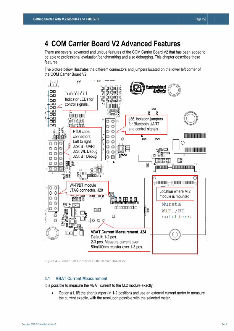
The picture below illustrates the different connectors and jumpers located on the lower left corner of the COM Carrier Board V2.
Figure 4 – Lower Left Corner of COM Carrier Board V2
4.1 VBAT Current Measurement
It is possible to measure the VBAT current to the M.2 module exactly.
Option #1, lift the short jumper (in 1-2 position) and use an external current meter to measure the current exactly, with the resolution possible with the selected meter.
VBAT Current Measurement, J24 Default: 1-2 pos. 2-3 pos. Measure current over 50milliOhm resistor over 1-3 pos.
J36, isolation jumpers for Bluetooth UART and control signals.
Indicator LEDs for control signals.
Wi-Fi/BT module JTAG connector, J28
FTDI cable connectors, Left to right: J29: BT UART J26: WL Debug J23: BT Debug
Location where M.2 module is mounted

Getting Started with M.2 Modules and i.MX 6/7/8 Page 23
Copyright 2019 © Embedded Artists AB Rev A
Note: make sure the current meter does not add a voltage drop more than 50-100mV maximum.
Option #2, move the short jumper to position 2-3. This will add a 50 milliOhm series resistor and it is possible to measure the voltage over this series resistor on pos 1 and 3.
Do not forget to move the short jumper back to position 1-2 after a measurement session.
4.2 VBAT 3.3V or 3.6V
It is possible to set VBAT to either 3.3V or 3.6V during run time. This is controlled via a I2C mapped GPIO. Setting VBAT to 3.6V can improve radio performance on the M.2 module. Note that setting VBAT to 3.6V is outside of the M.2 specification, but if the radio chip/module on the M.2 module is known to handle VBAT set to 3.6V then it can be an option to measure the added performance.
4.3 Support for 3.3V IO logic level (if M.2 module supports it)
The M.2 standard defines the IO voltage logic levels to a mixture of 1.8V and 3.3V. It is possible to set the 1.8V logic signals to 3.3V logic level during run time. This is controlled via a I2C mapped GPIO. Note that before doing this make sure the M.2 module used supports this feature. Not all of them do this.
Also not that this control only affects the controls signals that have 1.8V logic level, not the SDIO bus. The SDIO bus voltage level is controlled via other means.
4.4 Bluetooth UART Interception
It is possible to intercept/overtake the Bluetooth UART communication via connector J29. Insert a UART-to-USB bridge cable from FTDI (TTL-232R-3V3) into J29 and use a PC application to communicate directly with the Bluetooth part of the M.2 module.
Cypress has a tool called CyBluetool that can be used to debug Bluetooth communication problems. The program and instructions on how to use it can be downloaded here: https://community.cypress.com/docs/DOC-16475.
CyBluetool requires direct control of the UART and this is normally controlled by Linux. To disable that control:
1) Start the terminal program on the PC
2) Power on the board
3) Press space as soon as text appears in the terminal program to stop in the u-boot
4) Run this command:
=> setenv cmd_custom fdt set serial1 status disabled\;fdt set
/modem-reset status disabled
Note that this is one line and the => should not be typed. The "serial1" part of the command is COM board specific. Look at the table in section 3.5 and use the number in the device name. For example /dev/ttymcx1 becomes serial1, /dev/ttymxc4 becomes serial 4.
5) Run this command to save the setting:
=> saveenv
Getting Started with M.2 Modules and i.MX 6/7/8 Page 24
Copyright 2019 © Embedded Artists AB Rev A
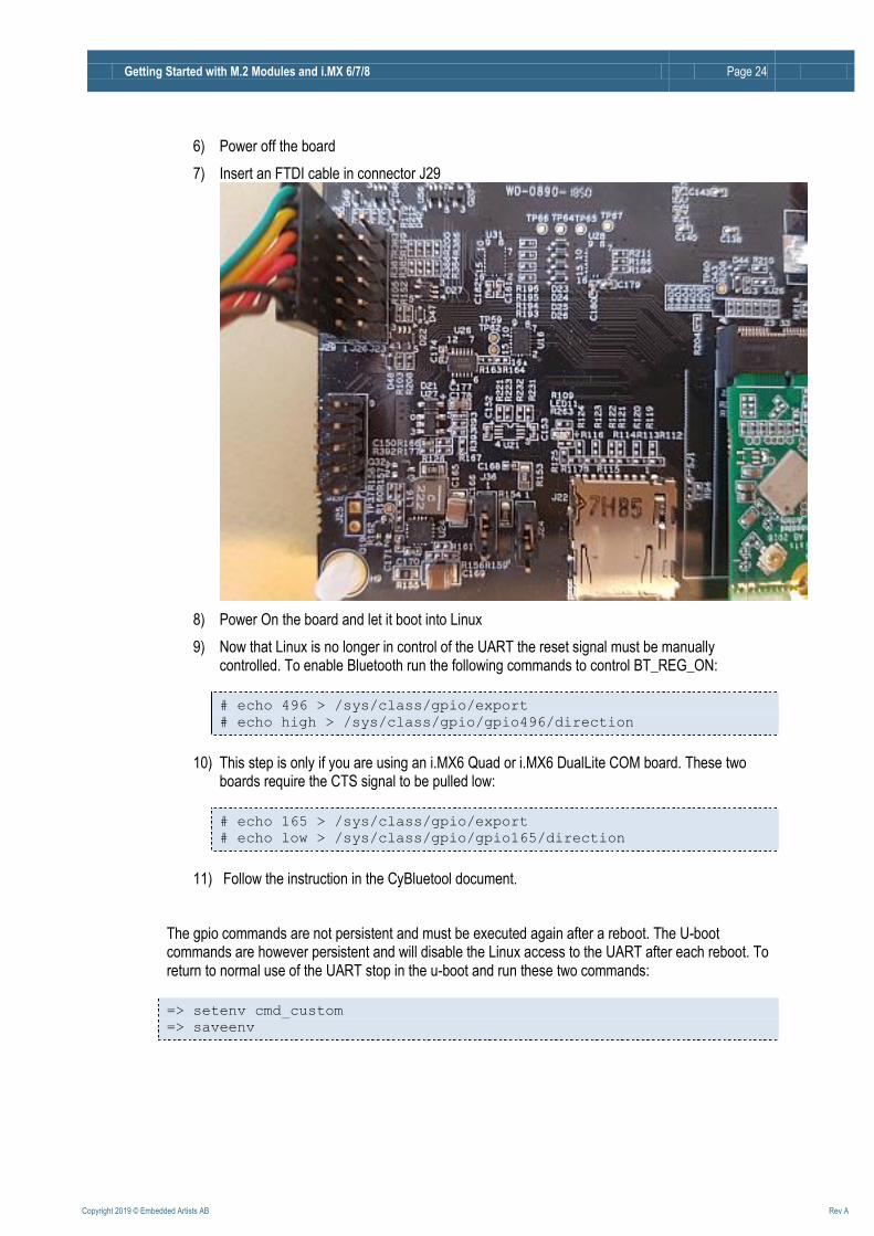
6) Power off the board
7) Insert an FTDI cable in connector J29
8) Power On the board and let it boot into Linux
9) Now that Linux is no longer in control of the UART the reset signal must be manually controlled. To enable Bluetooth run the following commands to control BT_REG_ON:
# echo 496 > /sys/class/gpio/export
# echo high > /sys/class/gpio/gpio496/direction
10) This step is only if you are using an i.MX6 Quad or i.MX6 DualLite COM board. These two boards require the CTS signal to be pulled low:
# echo 165 > /sys/class/gpio/export
# echo low > /sys/class/gpio/gpio165/direction
11) Follow the instruction in the CyBluetool document.
The gpio commands are not persistent and must be executed again after a reboot. The U-boot commands are however persistent and will disable the Linux access to the UART after each reboot. To return to normal use of the UART stop in the u-boot and run these two commands:
=> setenv cmd_custom
=> saveenv

Getting Started with M.2 Modules and i.MX 6/7/8 Page 25
Copyright 2019 © Embedded Artists AB Rev A
4.5 Dual UART Debug Channels and JTAG
In a cooperation with Murata, Cypress and Embedded Artists a number of pins on the M.2 connector have been defines to carry UART debug channels as well as JTAG signals to the chipset on the M.2 module. Note that not all M.2 modules support all debug channels.
Connector J26 carry the Wi-Fi UART debug channel. Connect a UART-to-USB bridge cable from FTDI (TTL-232R-3V3) into J26 and use a PC terminal application to get access to the debug interface.
Connector J23 carry the Bluetooth UART debug channel. Connect a UART-to-USB bridge cable from FTDI (TTL-232R-3V3) into J26 and use a PC terminal application to get access to the debug interface.
J28 is a JTAG debug interface to the chipset on the M.2 module.
Note that using these debug interfaces typically requires understanding and access to the firmware
4.6 Audio Codec Multiplexing
Audio interface routing between i.MX processor on COM board, M.2 module and audio codec are three corners in a triangle. With multiplexing, any corner can connect to any other corner. There are three options, as listed below. Control is done in run time with two I2C mapped GPIOs.
Option #1, connect M.2 module audio interface to audio codec on COM Carrier Board V2.
Option #2, connect M.2 module audio interface to i.MX processor on the COM board.
Option #3, connect audio interface from i.MX processor (on the COM board) to audio codec on COM Carrier Board V2. This is the default when no M.2 module is used.
Getting Started with M.2 Modules and i.MX 6/7/8 Page 26
Copyright 2019 © Embedded Artists AB Rev A
5 Software Update The first software version that supports the COM Carrier Board V2 is Linux kernel 4.14.78 and u-boot v2018.03. The fastest way to get started is to download a prepared set of files for the COM board you are using from http://imx.embeddedartists.com .
Instructions on how to flash that software is available in the iMX Working with Yocto document.
This section is an abbreviated version of that document.
5.1 Linux Host Setup
5.1.1 Introduction
The Yocto build system requires a Linux host machine. You can either run this host as a standalone / native computer or as a virtual machine on, for example, a Microsoft Windows PC. The minimum available hard disk space is 50 GB, but it is recommended that the host machine has at least 120 GB to be able to build the largest image / distribution.
Several Linux distributions are supported by the Yocto project. Please refer to the Supported Linux Distributions section in the Yocto reference manual for a complete list.
The instructions in this document have been tested on an Ubuntu 14.04. The iMX Working with Yocto document explains how to setup a virtual machine.
5.1.2 Required Packages
The Yocto Project requires several packages to be installed on the host machine. If you are using any of the distributions in section 5.1.1 follow the instructions below. If you, however, are using another distribution refer to the Required Packages for the Host Development System section in the Yocto reference manual.
$ sudo apt-get install gawk wget git-core diffstat unzip texinfo
gcc-multilib build-essential chrpath socat
$ sudo apt-get install libsdl1.2-dev xterm sed cvs subversion
coreutils texi2html docbook-utils python-pysqlite2 help2man make
gcc g++ desktop-file-utils libgl1-mesa-dev libglu1-mesa-dev
mercurial autoconf automake groff curl lzop asciidoc
$ sudo apt-get install u-boot-tools
5.1.3 Install the repo tool
The repo tool has been developed to make it easier to manage multiple Git repositories. Instead of
downloading each repository separately the repo tool can download all with one instruction.
Download and install the tool by following the instructions below.
1. Create a directory for the tool. The example below creates a directory named bin in your
home folder.
$ mkdir ~/bin
2. Download the tool
$ curl http://commondatastorage.googleapis.com/git-repo-
downloads/repo > ~/bin/repo
Getting Started with M.2 Modules and i.MX 6/7/8 Page 27
Copyright 2019 © Embedded Artists AB Rev A
3. Make the tool executable
$ chmod a+x ~/bin/repo
4. Add the directory to the PATH variable. The line below could be added to your .bashrc file so the path is available in each started shell/terminal
$ export PATH=~/bin:$PATH
5.1.4 Download Yocto recipes
The Yocto project consists of many recipes used when building an image. These recipes come from several repositories and the repo tool is used to download these repositories.
In step 3 below a branch must be selected of the ea-yocto-base repository. The table below lists the branches that support the M.2 modules.
Branch name Description
ea-4.14.78 u-boot: 2018.03. Linux: 4.14.78.
Table 1 - ea-yocto-base branches
1. Create a directory for the downloaded files (ea-bsp in the example below)
$ mkdir ea-bsp
$ cd ea-bsp
2. Configure Git if you haven’t already done so. Change “Your name” to your actual name and “Your e-mail” to your e-mail address.
$ git config --global user.name “Your name”
$ git config --global user.email “Your e-mail”
3. Initialize repo. The file containing all needed repositories is downloaded in this step. Change <selected branch> to a branch name according to Table 1.
$ repo init -u https://github.com/embeddedartists/ea-yocto-base -b
<selected branch>
4. Start to download files
$ repo sync
All files have now been downloaded into the ea-bsp directory. Most of the files will actually be
available in the sub-directory called sources.
5.2 Building Images
Yocto is using the BitBake tool to generate complete Linux images/distributions, that is, all needed to boot and run a Linux system. This is typically boot loader(s), Linux kernel, and root file system with selected utilities and applications.
5.2.1 Available Images
The recipes that have been downloaded contain many different images. The table below describes the ones relevant when working with the M.2 modules.
Getting Started with M.2 Modules and i.MX 6/7/8 Page 28
Copyright 2019 © Embedded Artists AB Rev A
Image name Description
meta-toolchain Builds an installable toolchain (cross-complier)
ea-image-base Only available on branch ea-4.14.78 and later. Based on core-image-base and added packages for peripheral testing and verification
5.2.2 Machine Configurations
A machine configuration must be specified before a build can be started.
The table below contains the machine configurations available for Embedded Artists boards. It is also
possible to find the configuration files in the directory ~/ea-bsp/sources/meta-
ea/conf/machine.
Machine Description
imx6sxea-com Machine configuration for Embedded Artists i.MX 6 SoloX COM Board / Kit
imx6qea-com Machine configuration for Embedded Artists i.MX 6 Quad COM Board / Kit
imx6dlea-com Machine configuration for Embedded Artists i.MX 6 DualLite COM Board / Kit
imx6ulea-com Machine configuration for Embedded Artists i.MX 6 UltraLite COM Board / Kit
imx7dea-ucom Machine configuration for Embedded Artists i.MX 7 Dual uCOM Board / Kit
imx7dea-com Machine configuration for Embedded Artists i.MX 7 Dual COM Board / Kit
imx8mqea-com Machine configuration for Embedded Artists i.MX8M Quad COM Board / Kit
5.2.3 Initialize Build
Before starting the build it must be initialized. In this step the build directory and local configuration files are created.
A distribution must be selected when initializing the build, see iMX Working with Yocto for different
alternatives. For headless setups (i.e. without a display) use fsl-imx-fb. Note that the i.MX8M
does not support fsl-imx-fb so use fsl-imx-wayland instead.
In the example below the machine imx6sxea-com, the build directory build_dir and the
fsl-imx-fb distribution (see iMX Working with Yocto for other distributions) is selected.
$ DISTRO=fsl-imx-fb MACHINE=imx6sxea-com source ea-setup-
release.sh -b build_dir
Restart a Build
If you need to restart a build in a new terminal window or after a restart of the host computer you don’t
need to run the ea-setup-release.sh script again. Instead you run the setup-
environment script. If you don’t run the setup-environment script you won’t have access
to needed tools and utilities, such as bitbake.
Getting Started with M.2 Modules and i.MX 6/7/8 Page 29
Copyright 2019 © Embedded Artists AB Rev A
$ source setup-environment build_dir
5.2.4 Starting the Build
Everything has now been setup to start the actual build. The example below shows how the ea-
image-base image is being built. Please note that depending on the capabilities of your host
computer building an image can take many hours.
$ bitbake ea-image-base
When the build has finished the images will be available in the directory specified below. Please note that this directory will be different if you are using another build directory or machine configuration.
~/ea-bsp/build_dir/tmp/deploy/images/imx6sxea-com.
Go to chapter 5.3 for instructions of how to deploy images to the target hardware.
5.3 Deploying Images
NXP's Manufacturing Tool currently exists in two versions. MFGTool is the old version and UUU is the new version.
MFGTool UUU
MFGTool version V2 V3
Actively developed No Yes
OS Support Windows only Windows + Linux
Source Code Available No Yes, GitHub
As of May 2019 Embedded Artists plan to keep MFGTool support for old kernel releases (i.e. prior to Linux 4.14.78). For Linux 4.14.78 there will be a transition time where both MFGTool and UUU zip files will be available but at some point only the UUU zip file will be updated. For all releases after Linux 4.14.78, only UUU will be supported.
5.3.1 Manufacturing Tool
NXP’s Manufacturing Tool (MFGTool) can be used to write images to the board. This tool is sending files and instructions over USB and the board must be set in OTG boot mode for it to work.
At the moment the tool is only available for Microsoft Windows and a version which has been prepared for Embedded Artists boards is available on http://imx.embeddedartists.com/ for the board you are using.
5.3.1.1 Download the Tool
Download the zip file containing the manufacturing tool from http://imx.embeddedartists.com/
Unpack this zip file somewhere on your computer running Microsoft Windows. Below is a description of some of the content in the zip file.
- mfgtool (root): Contains the actual tool as well as vbs files which can be used to run a
specific download configuration.
- mfgtool/Document: Contains documentation for the manufacturing tool. This
documentation has been written by NXP.
Getting Started with M.2 Modules and i.MX 6/7/8 Page 30
Copyright 2019 © Embedded Artists AB Rev A
- mfgtool/Profiles/Linux/OS Firmware/ucl2.xml: This file contains the
actual download configurations.
- mfgtool/Profiles/Linux/OS Firmware/files: Contains pre-compiled
versions of images. The tool will look in this directory when selecting images to download to the board.
5.3.1.2 Prepare hardware
Begin by reading the Getting Started document for the board you are using. It shows how to setup the board and also gives an overview of the hardware.
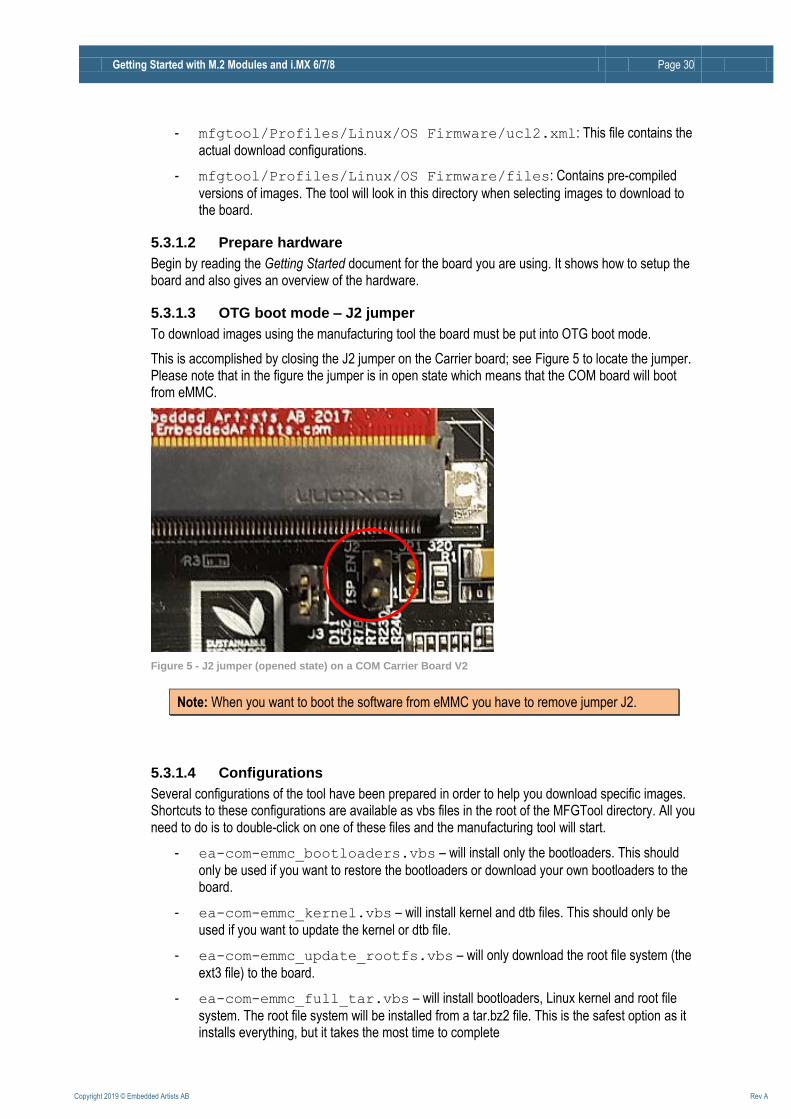
5.3.1.3 OTG boot mode – J2 jumper
To download images using the manufacturing tool the board must be put into OTG boot mode.
This is accomplished by closing the J2 jumper on the Carrier board; see Figure 5 to locate the jumper. Please note that in the figure the jumper is in open state which means that the COM board will boot from eMMC.
Figure 5 - J2 jumper (opened state) on a COM Carrier Board V2
Note: When you want to boot the software from eMMC you have to remove jumper J2.
5.3.1.4 Configurations
Several configurations of the tool have been prepared in order to help you download specific images. Shortcuts to these configurations are available as vbs files in the root of the MFGTool directory. All you need to do is to double-click on one of these files and the manufacturing tool will start.
- ea-com-emmc_bootloaders.vbs – will install only the bootloaders. This should
only be used if you want to restore the bootloaders or download your own bootloaders to the board.
- ea-com-emmc_kernel.vbs – will install kernel and dtb files. This should only be
used if you want to update the kernel or dtb file.
- ea-com-emmc_update_rootfs.vbs – will only download the root file system (the
ext3 file) to the board.
- ea-com-emmc_full_tar.vbs – will install bootloaders, Linux kernel and root file
system. The root file system will be installed from a tar.bz2 file. This is the safest option as it installs everything, but it takes the most time to complete

Getting Started with M.2 Modules and i.MX 6/7/8 Page 31
Copyright 2019 © Embedded Artists AB Rev A
5.3.1.5 Download Your Own Images
The simplest way to download your own images is to replace the existing file(s) with your file(s). If you keep the file names intact the vbs files will download your version of the file.
The files to replace are in the Profiles\Linux\OS Firmware\files\ folder.
5.3.1.6 Run the Tool
Double click on one of the vbs files to start the manufacturing tool. If the tool can find the board it will write “HID-compliant device” in the status field, see Figure 6 below. If it cannot find the board it will write “No Device Connected”.
Figure 6 - Manufacturing Tool
Click the Start button to start the download of files. If all operations are successful the progress bars will turn green, see Figure 7. Click the Stop button and then Exit to close the manufacturing tool. If an operation fails the progress bars will turn red. In this case it can be helpful to have a look at the log
MfgTool.log which is found in the same directory as the manufacturing tool.
Figure 7 Manufacturing Tool successful download
Remove jumper J2 and power cycle the board to boot into Linux.
5.3.2 UUU
UUU (Universal Update Utility) is version 3 of MFGTool but it has been rewritten, is publicly available on GitHub (https://github.com/NXPmicro/mfgtools) and it can be run on both Windows and Linux while the older versions of MFGTool were limited to Windows only.
UUU can be used to write images to the board. This tool is sending files and instructions over USB and the board must be set in OTG boot mode for it to work.
Getting Started with M.2 Modules and i.MX 6/7/8 Page 32
Copyright 2019 © Embedded Artists AB Rev A
Starting with Linux 4.14.78, a uuu-zip file will be made available in addition to the mfgtool zip files on http://imx.embeddedartists.com/ for the board you are using. i.MX 8M COM boards only support the uuu format and will not have an mfgtool zip file.
Prerequisites:
Ubuntu 16.04 or above, 64-bit
Windows 10, 64-bit
Windows 7, 64-bit - note that there might be problems with drivers and that it might not even work with the driver fixes applied even if the documentation says it does. The Windows 7 specific instructions can be found here: https://github.com/NXPmicro/mfgtools/wiki/WIN7-User-Guide
Useful links:
UUU on GitHub: https://github.com/NXPmicro/mfgtools
UUU release page: https://github.com/NXPmicro/mfgtools/releases
5.3.2.1 Download the Tool
Download the zip file for the board you are using from http://imx.embeddedartists.com/
Unpack this zip file somewhere on your computer. Below is a description of some of the content in the zip file.
- uuu (root): Contains a README file.
- uuu/*.uuu: The different download configurations.
- uuu/files/: Contains pre-compiled versions of images. The tool will look in this directory
when selecting images to download to the board.
Unlike the older MFGTool the uuu zip file does not include the tool itself. The README file contains a link to where the latest binaries can be downloaded (https://github.com/NXPmicro/mfgtools/releases) . Download either uuu.exe (for Windows) or uuu for Linux and save the file in the same folder as the README file.
5.3.2.2 Prepare hardware
The instructions here are identical to the ones for MFGTool available in 5.3.1.2
5.3.2.3 OTG boot mode – J2 jumper
The instructions here are identical to the ones for MFGTool available in 5.3.1.3
5.3.2.4 Configurations
Several configurations (*.uuu files) for the tool have been prepared in order to help you download specific images.
- bootloader.uuu – will install only the bootloaders. This should only be used if you want
to restore the bootloaders or download your own bootloaders to the board.
- bootloader_combined.uuu – will install only the bootloaders. This is a faster
alternative to bootloader.uuu but it requires a binary where SPL and the u-boot have been combined (see below). This should only be used if you want to restore the bootloaders or download your own bootloaders to the board.
Getting Started with M.2 Modules and i.MX 6/7/8 Page 33
Copyright 2019 © Embedded Artists AB Rev A
- kernel.uuu – will install kernel and dtb files. This should only be used if you want to
update the kernel or dtb files.
- full_tar.uuu – will install bootloaders, Linux kernel and root file system. The root file
system will be installed from a tar.bz2 file.
- raw_sdcard_example.uuu – will overwrite the eMMC with the content of an sdcard
file. The sdcard file is copied directly to the eMMC overwriting everything including bootloaders, Linux kernel and file system.
If you want to create the combined binary to use with bootloader_combined.uuu run the following commands in Linux:
$ dd if=SPL of=spl_and_uboot.bin bs=1024
$ dd if=u-boot.img of=spl_and_uboot.bin bs=1024 seek=68
5.3.2.5 Download Your Own Images
The uuu zip file that you download from http://imx.embeddedartists.com/ contain the latest build from Embedded Artists.
The simplest way to download your own images is to replace the existing file(s) with your own file(s). If you keep the file names intact the *.uuu configurations will download your version of the file.
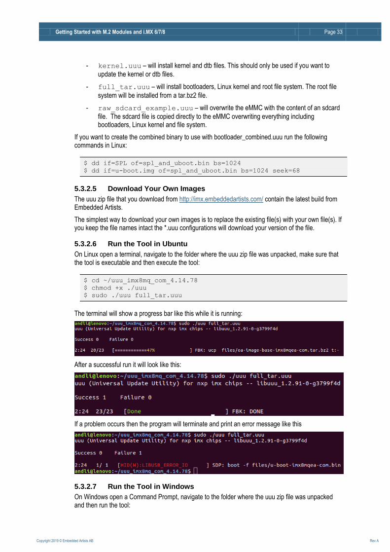
5.3.2.6 Run the Tool in Ubuntu
On Linux open a terminal, navigate to the folder where the uuu zip file was unpacked, make sure that the tool is executable and then execute the tool:
$ cd ~/uuu_imx8mq_com_4.14.78
$ chmod +x ./uuu
$ sudo ./uuu full_tar.uuu
The terminal will show a progress bar like this while it is running:
After a successful run it will look like this:
If a problem occurs then the program will terminate and print an error message like this
5.3.2.7 Run the Tool in Windows
On Windows open a Command Prompt, navigate to the folder where the uuu zip file was unpacked and then run the tool:
Getting Started with M.2 Modules and i.MX 6/7/8 Page 34
Copyright 2019 © Embedded Artists AB Rev A
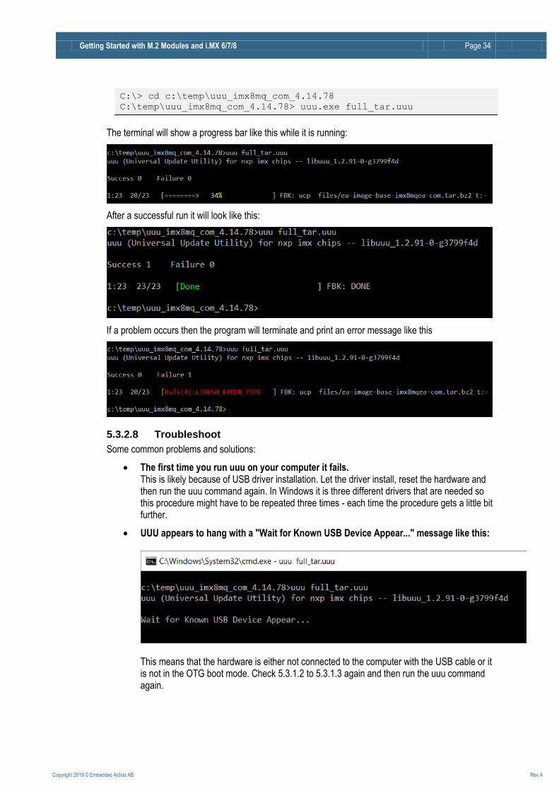
C:\> cd c:\temp\uuu_imx8mq_com_4.14.78
C:\temp\uuu_imx8mq_com_4.14.78> uuu.exe full_tar.uuu
The terminal will show a progress bar like this while it is running:
After a successful run it will look like this:
If a problem occurs then the program will terminate and print an error message like this
5.3.2.8 Troubleshoot
Some common problems and solutions:
The first time you run uuu on your computer it fails. This is likely because of USB driver installation. Let the driver install, reset the hardware and then run the uuu command again. In Windows it is three different drivers that are needed so this procedure might have to be repeated three times - each time the procedure gets a little bit further.
UUU appears to hang with a "Wait for Known USB Device Appear..." message like this:
This means that the hardware is either not connected to the computer with the USB cable or it is not in the OTG boot mode. Check 5.3.1.2 to 5.3.1.3 again and then run the uuu command again.
Getting Started with M.2 Modules and i.MX 6/7/8 Page 35
Copyright 2019 © Embedded Artists AB Rev A
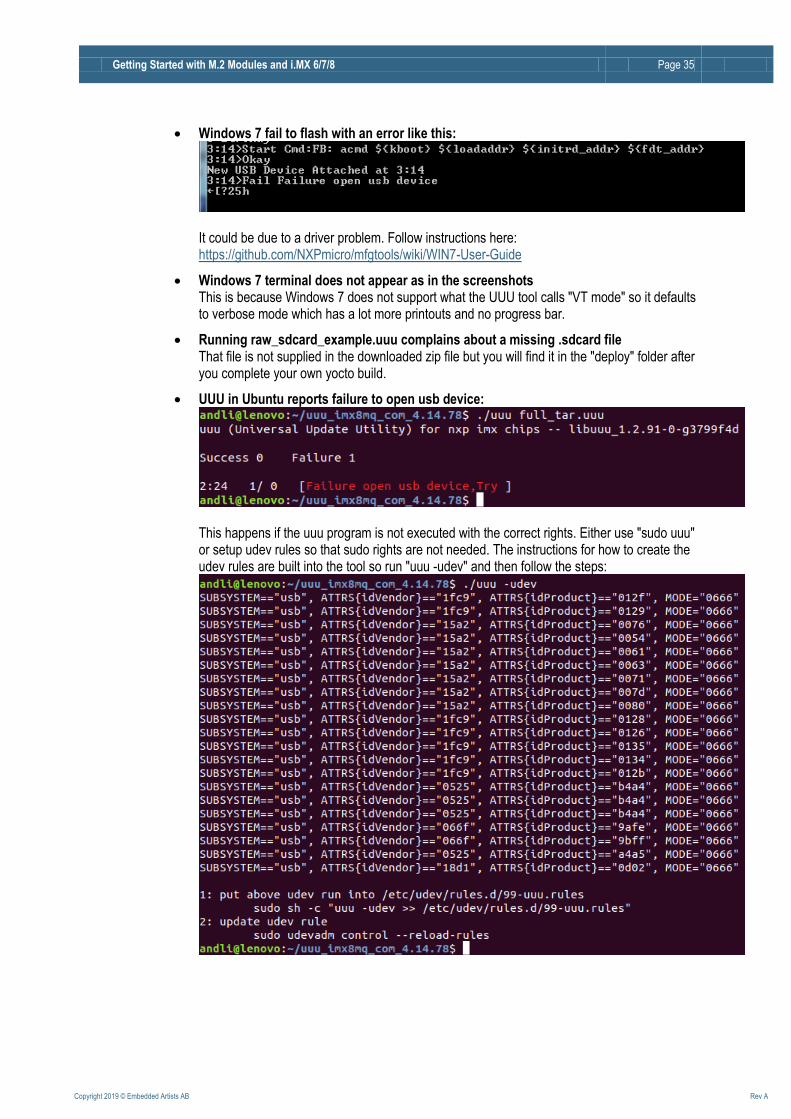
Windows 7 fail to flash with an error like this:
It could be due to a driver problem. Follow instructions here: https://github.com/NXPmicro/mfgtools/wiki/WIN7-User-Guide
Windows 7 terminal does not appear as in the screenshots This is because Windows 7 does not support what the UUU tool calls "VT mode" so it defaults to verbose mode which has a lot more printouts and no progress bar.
Running raw_sdcard_example.uuu complains about a missing .sdcard file That file is not supplied in the downloaded zip file but you will find it in the "deploy" folder after you complete your own yocto build.
UUU in Ubuntu reports failure to open usb device:
This happens if the uuu program is not executed with the correct rights. Either use "sudo uuu" or setup udev rules so that sudo rights are not needed. The instructions for how to create the udev rules are built into the tool so run "uuu -udev" and then follow the steps:

Getting Started with M.2 Modules and i.MX 6/7/8 Page 36
Copyright 2019 © Embedded Artists AB Rev A
5.4 Building without Yocto
5.4.1 Stand-alone Toolchain
To be able to build your own application or, for example, u-boot and the Linux kernel outside of Yocto you need a toolchain. The toolchain consists of cross-compiler, linker, and necessary libraries. As mentioned in section 5.2.1 there is an image named meta-toolchain that will create the necessary toolchain.
1. Build the image
$ bitbake meta-toolchain
2. The build will result in a file located at <build dir>/tmp/deploy/sdk. The exact
name of the file depends on several, but in our example it is called: fsl-imx-fb-glibc-x86_64-meta-toolchain-cortexa9hf-neon-
toolchain-4.14-sumo.sh
3. Install the toolchain
$ cd <build dir>/tmp/deploy/sdk
$ sudo ./fsl-imx-fb-glibc-x86_64-meta-toolchain-cortexa9hf-neon-
toolchain-4.14-sumo.sh
4. If you select the default settings the toolchain will in this example be installed in /opt/fsl-imx-fb/ 4.14-sumo
5. Before building an application run the command below to setup environment variables
$ source /opt/fsl-imx-fb/4.14-sumo/environment-setup-cortexa9hf-
neon-poky-linux-gnueabi
6. You can verify that the environment variables has been correctly setup by running the command below that will show the version of the GCC compiler used.
$ $CC –-version
arm-poky-linux-gnueabi-gcc (GCC) 7.3.0
...
NOTE 1: Setting up environment variables in step 5 may overwrite other variables you already have in your environment. It is, for example, not recommended to do this in the same terminal where you run bitbake to build Yocto images.
It is recommended to build this toolchain on your host computer and where you will do the development and that you build for the same board as for example i.MX6UL/i.MX7Dual have a different (ARM7) cross compiler than other i.MX6 processors (ARM9).
5.4.2 Build Linux kernel from source code
You can build the Linux kernel outside of Yocto by following the instructions in this section. Please note that it is recommended that the kernel is built by Yocto when you are generating your final distribution images since there can be dependencies between the root file system and the kernel.
Getting Started with M.2 Modules and i.MX 6/7/8 Page 37
Copyright 2019 © Embedded Artists AB Rev A
The instructions in this section assume that you have built and installed the toolchain as described in section 5.4.1 above.
Setup the environment variables for the toolchain. We are using the same installation path as described in section 5.4.1 above. If you have installed the toolchain in a different path use that path in the instructions below.
$ source /opt/fsl-imx-fb/4.14-sumo/environment-setup-cortexa9hf-
neon-poky-linux-gnueabi
Get the source code from the Embedded Artists GitHub repository. In this example we are checking out branch ea_4.14.78.
$ git clone https://github.com/embeddedartists/linux-imx.git
$ cd linux-imx
$ git checkout ea_4.14.78
Use Embedded Artists kernel configurations.
$ make ea_imx_defconfig
(Optional) If you want to change kernel configurations you can at this point run the menuconfig tool.
$ make menuconfig
Build the kernel.
$ make
When the build process has finished the kernel will be available here: arch/arm/boot/zImage.
Device tree files are available in the following directory: arch/arm/boot/dts. A compiled device
tree file has the file extension dtb.
Updating the system
To update the system use manufacturing tool as described in 5.3 . For alternative ways of updating see the iMX Working with Yocto document.
5.4.3 Build u-boot from source code
You can build u-boot outside of Yocto by following the instructions in this section.
The instructions in this section assume that you have built and installed the toolchain as described in section 5.4.1 above.
Setup the environment variables for the toolchain. We are using the same installation path as described in section 5.4.1 above. If you have installed the toolchain in a different path use that path in the instructions below.
$ source /opt/fsl-imx-fb/4.14-sumo/environment-setup-cortexa9hf-
neon-poky-linux-gnueabi
Get the source code from the Embedded Artists GitHub repository. In this example we are checking out branch ea_v2018.03.

Getting Started with M.2 Modules and i.MX 6/7/8 Page 38
Copyright 2019 © Embedded Artists AB Rev A
$ git clone https://github.com/embeddedartists/uboot-imx.git
$ cd uboot-imx
$ git checkout ea_v2018.03
Use the Embedded Artists configuration for the COM board you are using. In the example below the configuration for the iMX6 SoloX COM board is used.
$ make mx6sxea-com_config
Build the bootloader.
$ make
When the build process has finished the u-boot image (and in some cases SPL) will be available directly in the uboot-imx directory.
Updating the system
Use the manufacturing tool as described in section 5.3.1 to update the system with the new u-boot image and possibly SPL if your board requires it.
5.5 NVRAM
<TBD>Describe NVRAM and how it is updated/modified
5.6 Firmware
<TBD>Describe how to update the firmware for the M.2 modules, if needed
5.7 WinSCP
WinSCP is a Windows program that is very useful to transfer files from the PC to the target hardware. It can also be used to transfer the files from a yocto build to the PC where the files can be flashed using MFGTool/UUU as described in section 5.3 .
5.7.1 Download and Install
Download the program from https://winscp.net/eng/download.php and install it.
5.7.2 Connect to Target
When WinSCP is started it asks for connection information. Enter the following information
Field Value
User name root
Password pass
Host name The IP number of the target (found by running "ifconfig" on the target)
File protocol SCP or SFTP
Getting Started with M.2 Modules and i.MX 6/7/8 Page 39
Copyright 2019 © Embedded Artists AB Rev A
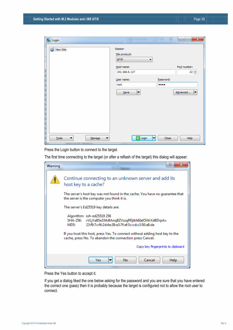
Press the Login button to connect to the target.
The first time connecting to the target (or after a reflash of the target) this dialog will appear:
Press the Yes button to accept it.
If you get a dialog liked the one below asking for the password and you are sure that you have entered the correct one (pass) then it is probably because the target is configured not to allow the root user to connect.

Getting Started with M.2 Modules and i.MX 6/7/8 Page 40
Copyright 2019 © Embedded Artists AB Rev A
Allowing root access is a huge security threat and it should never be allowed in a production system. To allow it during development in a controlled environment is ok and to do it run the following command on the target and then reboot to apply the change:
# sed -i 's/#PermitRoot/PermitRoot/' /etc/ssh/sshd_config
If you prefer to edit the file manually then open /etc/ssh/sshd_config and search for
#PermitRootLogin yes
and remove the preceding # sign.
Note that the command is persistent but needs to be executed again if you reflash the file system.
Getting Started with M.2 Modules and i.MX 6/7/8 Page 41
Copyright 2019 © Embedded Artists AB Rev A
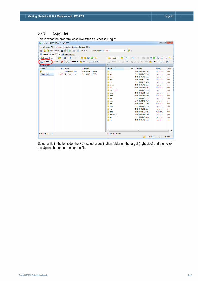
5.7.3 Copy Files
This is what the program looks like after a successful login:
Select a file in the left side (the PC), select a destination folder on the target (right side) and then click the Upload button to transfer the file.