getting started with batchreactor - process simulation · be calculated for both process and...
TRANSCRIPT

© 2014 ProSim S.A. All rights reserved.
Example: simulation of the Chlorotoluene chloration
Getting started with
BatchReactor
© 2
014
Pro
Sim
S.A
. A
ll rights
reserv
ed
.
2
This document presents the different steps to follow in order to
simulate a batch reactor synthesis using BatchReactor software.
This presentation is supported with an example: the chloration of
the chlorotoluene.
This example is available in the BatchReactor example directory
( reactor2.pbpr input file)
The summary of this Getting Started is:
Part 1 – Description of the example
Part 2 – General points on the software interface
Part 3 – Description of the different steps to simulate the example
Introduction

© 2
014
Pro
Sim
S.A
. A
ll rights
reserv
ed
.
3
Part 1
Description of the example:
• Description of the reaction system
• Compounds and thermodynamic model
• Description of the equipments
• Operating mode

© 2
014
Pro
Sim
S.A
. A
ll rights
reserv
ed
.
4
Gaseous chlorine is fed into a liquid chlorotoluene charge. The
reaction takes place in liquid phase. A nitrogen sweeping is
maintained during the reaction.
The main reaction is as follow:
C7H7Cl + Cl2 C7H6Cl2 + HCl
Chloromethyl chloro benzene (ACl) and hydrogen chloride are
produced. The reaction rate is found to be expressed with a partial
order equal to 1 for each reactant, a frequency factor
Ko = 2.7203e17 mol/l .s and energy activation
Ea = 130320 J /mol
Description of the reaction system

© 2
014
Pro
Sim
S.A
. A
ll rights
reserv
ed
.
5
Side reaction is:
C7H6Cl2 + Cl2 C7H5Cl3 + HCl
Chloro-2-dichloro methylbenzene (dichloride) and hydrogen
chloride are formed. The kinetic law is also expressed with
partial order equal to 1 for each reactant, Ko = 580 mol / l .s
and
Ea = 42200 J /mol
The heat of reactions are calculated from the standard
enthalpies of formation at 298 K (perfect gas state).
Description of the reaction system

© 2
014
Pro
Sim
S.A
. A
ll rights
reserv
ed
.
6
The compounds involved are:
- Chlorotoluene (CT)
- Chloromethyl chloro benzene (ACl)
- Chloro-2-dichloro methylbenzene (dichloride)
- Chlorine
- Hydrogen chloride
- Nitrogen
The thermodynamic model selected is NRTL. Binaries
interaction parameters expressed in cal/mol are:
CT-ACl
CT- Dichloride
ACl-Dichloride
-707,3
-1246
64,339
775,31
1463,5
-79,04
0,1939
0,1584
0,4097
Compounds and thermodynamic model
© 2
014
Pro
Sim
S.A
. A
ll rights
reserv
ed
.
7
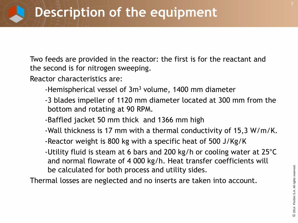
Two feeds are provided in the reactor: the first is for the reactant and
the second is for nitrogen sweeping.
Reactor characteristics are:
-Hemispherical vessel of 3m3 volume, 1400 mm diameter
-3 blades impeller of 1120 mm diameter located at 300 mm from the
bottom and rotating at 90 RPM.
-Baffled jacket 50 mm thick and 1366 mm high
-Wall thickness is 17 mm with a thermal conductivity of 15,3 W/m/K.
-Reactor weight is 800 kg with a specific heat of 500 J/Kg/K
-Utility fluid is steam at 6 bars and 200 kg/h or cooling water at 25°C
and normal flowrate of 4 000 kg/h. Heat transfer coefficients will
be calculated for both process and utility sides.
Thermal losses are neglected and no inserts are taken into account.
Description of the equipment

© 2
014
Pro
Sim
S.A
. A
ll rights
reserv
ed
.
8
The reactor is closed and equipped with a two-stage condenser. A vapor outlet is leaving the second stage and a liquid outlet collects both condensates
The first stage of the condenser has an exchange area of 15 m2 and the global heat transfer coefficient is 300 kcal/h m2 °C. It is cooled by 3000 kg/h of water at 20°C.
The second stage has an exchange area of 0,5 m2 and a global heat transfer coefficient is 300 kcal/h m2 °C. The service fluid is at -15°C with a flowrate of 100 Kg/h. Its specific heat is 0,7933 cal/g/K at -15°C.
Pressure drop in both stages are neglected.
Description of the equipment

© 2
014
Pro
Sim
S.A
. A
ll rights
reserv
ed
.
9
The reactor is charged with 2 400 kg of chlorotoluene at 25°C and
atmospheric pressure.
First step: heating
Total reflux is maintained until the temperature reach 58°C.
Nitrogen flow is 1 kg/h at 25°C and atmospheric pressure. The total
pressure is equal to the atmospheric pressure.
Second step: reaction
The reactor is fed during 2 hours with 60 kg/h of chlorine at 3 bar.
The nitrogen sweeping is maintained. The reactor temperature is
controlled at value of 62°C by acting on the cooling water flowrate.
PID controller parameters are :
-Minimum / maximum values 59°C / 65°C
-Type : feedback, P = -5, Ti = 500 s, Td = 0
-The valve is equal percentage with Cv = 30. Sampling time is
10 s.
Operating mode

© 2
014
Pro
Sim
S.A
. A
ll rights
reserv
ed
.
10
Part 2
General points on the software interface:
• The main window
• Using the menu bar
• Choosing the unit system
• Create a new simulation file

© 2
014
Pro
Sim
S.A
. A
ll rights
reserv
ed
.
11
Menu bar
Scenario
view
Tools bar
Topology
panel
Flowsheet
view
The main window

© 2
014
Pro
Sim
S.A
. A
ll rights
reserv
ed
.
12
File management
(new, open, save, save
as, close)
Steps and events
connections
Units management
Units
conversion Numerical
parameters
Graphical objects
(forms, pictures, text)
Sheet
properties
Copy flowsheet
Last simulation
results
Synopsis
Copy, cut,
paste, delete
View
compounds list
Compounds,
thermodynamic,
chemical reactions
Start
simulation
Calculator
Report
parameters
Bulk
properties
Using the menu bar

© 2
014
Pro
Sim
S.A
. A
ll rights
reserv
ed
.
13
1- Select a predefined
system and click on
“Apply system”
2- Change a given unit
by another by clicking
on the name
3- Click on OK to validate
Choosing the unit system

© 2
014
Pro
Sim
S.A
. A
ll rights
reserv
ed
.
14
1- Click on « create a new document »
3- Open the synopsis
(optional)
4 – Fill the form
2- Save the file
Create a new simulation file

© 2
014
Pro
Sim
S.A
. A
ll rights
reserv
ed
.
15
Part 3
Description of the different steps to simulate
the example
• Phase 1: Select your compounds
• Phase 2: Select your thermodynamic model
• Phase 3: Describe the chemicals reactions
• Phase 4: Describe the reaction system
• Phase 5 : Describe the operating steps
• Phase 6: Run the simulation
• Phase 7: Display the simulation results

© 2
014
Pro
Sim
S.A
. A
ll rights
reserv
ed
.
16
2- Double click on
the calculator.
A calculator allow
you to define a list
of compounds and
a thermodynamic
model
1- Click on the
thermodynamics and
compounds icon
3- Click on “open a compounds file”
In this example, the compounds needed
for the simulation have been
stored in a private database called
“chlorotoluene.compounds”
Phase 1:Select your compounds

© 2
014
Pro
Sim
S.A
. A
ll rights
reserv
ed
.
17
4- Select
“chlorotoluene.compounds”
Phase 1:Select your compounds

© 2
014
Pro
Sim
S.A
. A
ll rights
reserv
ed
.
18
5- The compounds imported from the compounds file are listed.
CT, chlorine, hydrogen chloride and nitrogen are from the standard
databank. ACl and dichlorine have been created by the user.
Phase 1:Select your compounds

© 2
014
Pro
Sim
S.A
. A
ll rights
reserv
ed
.
19
1- Click on the “ Model” tab to open
the thermodynamic models
configuration window.
2- All thermodynamic models
available are listed here.
Use the scroll bar to go
through the complete list.
Select NRTL as the model to
be used in the example
Phase 2: Select your thermodynamic mode
© 2
014
Pro
Sim
S.A
. A
ll rights
reserv
ed
.
20
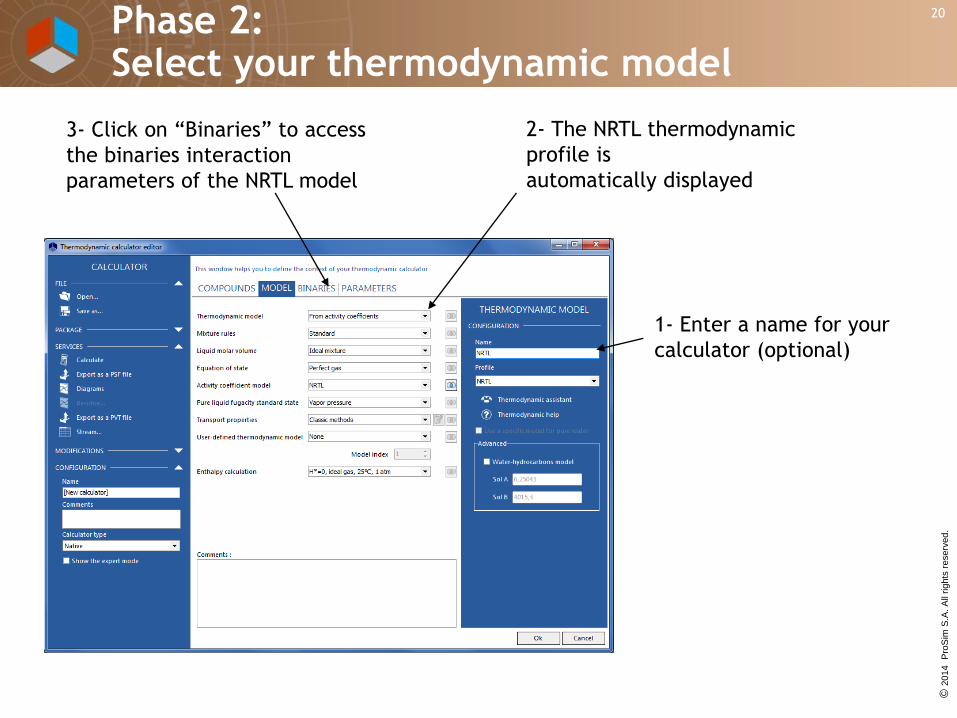
2- The NRTL thermodynamic
profile is
automatically displayed
3- Click on “Binaries” to access
the binaries interaction
parameters of the NRTL model
1- Enter a name for your
calculator (optional)
Phase 2: Select your thermodynamic model

© 2
014
Pro
Sim
S.A
. A
ll rights
reserv
ed
.
21
5- You can enter your binaries interaction parameters
Click on OK at the bottom to exit the thermodynamic calculator
Phase 2: Select your thermodynamic model
© 2
014
Pro
Sim
S.A
. A
ll rights
reserv
ed
.
22
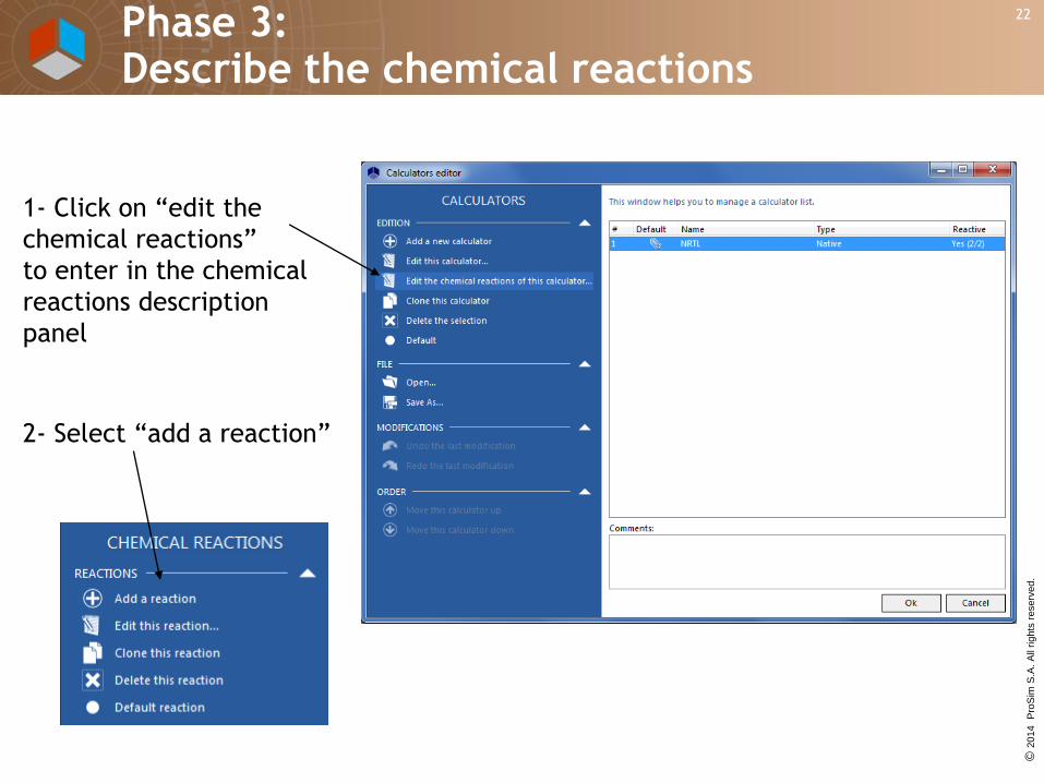
1- Click on “edit the
chemical reactions”
to enter in the chemical
reactions description
panel
2- Select “add a reaction”
Phase 3: Describe the chemical reactions
© 2
014
Pro
Sim
S.A
. A
ll rights
reserv
ed
.
23
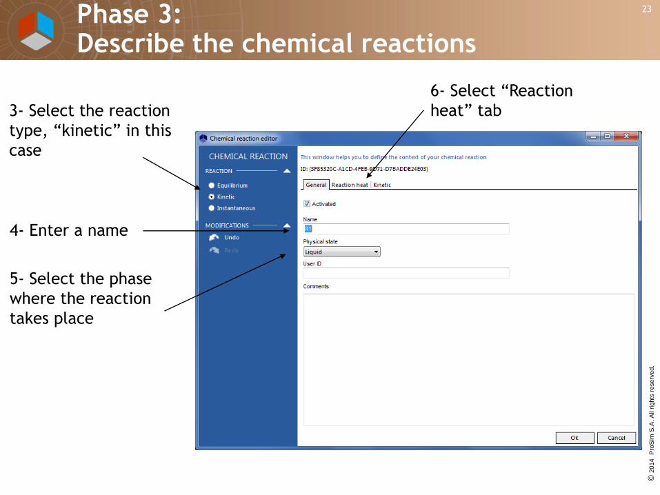
3- Select the reaction
type, “kinetic” in this
case
4- Enter a name
5- Select the phase
where the reaction
takes place
6- Select “Reaction
heat” tab
Phase 3: Describe the chemical reactions

© 2
014
Pro
Sim
S.A
. A
ll rights
reserv
ed
.
24
7- Select the reaction heat
model, calculated from
standard enthalpies of
formation
8- Select “Kinetic” tab
Phase 3: Describe the chemical reactions

© 2
014
Pro
Sim
S.A
. A
ll rights
reserv
ed
.
25
9- Select “Arrhenius”
and enter the activation
energy value
10- Select “Compounds” tab
Phase 3: Describe the chemical reactions

© 2
014
Pro
Sim
S.A
. A
ll rights
reserv
ed
.
26
11- Enter the stoichiometry coefficients (- for reactants
and + for products) and the orders of the considered reaction
12- Select
“Model” tab
Phase 3: Describe the chemical reactions

© 2
014
Pro
Sim
S.A
. A
ll rights
reserv
ed
.
27
13- Enter the
Frequency factor
14- Click on OK to exit
Phase 3: Describe the chemical reactions

© 2
014
Pro
Sim
S.A
. A
ll rights
reserv
ed
.
28
15- Enter the second
reaction:
- add a reaction
- describes the second
reaction as for the first
Phase 3: Describe the chemical reactions

© 2
014
Pro
Sim
S.A
. A
ll rights
reserv
ed
.
29
The main flowsheet allows the display of the reaction system (inlet and outlet storages, reactor and condensing system, ) and provide direct access to the different windows allowing the description.
1- Select the calculation mode
Phase 4: Describe the reaction system

© 2
014
Pro
Sim
S.A
. A
ll rights
reserv
ed
.
30
2- Select the relevant options:
-closed type
-with a condenser
-hemispherical bottom
-3 retreating-blades impeller
-joined external jacket
Phase 4: Describe the reaction system

© 2
014
Pro
Sim
S.A
. A
ll rights
reserv
ed
.
31
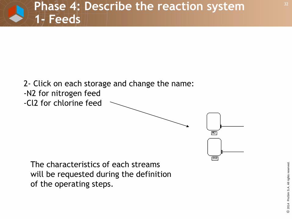
1- Drag and drop
an additional feed
Phase 4: Describe the reaction system 1- Feeds
© 2
014
Pro
Sim
S.A
. A
ll rights
reserv
ed
.
32
2- Click on each storage and change the name:
-N2 for nitrogen feed
-Cl2 for chlorine feed
The characteristics of each streams
will be requested during the definition
of the operating steps.
Phase 4: Describe the reaction system 1- Feeds

© 2
014
Pro
Sim
S.A
. A
ll rights
reserv
ed
.
33
Click on “Head
space”
Select « Other » and « Nitrogen » as compound
in the list (nitrogen blanketting)
Phase 4: Describe the reaction system 2- Reactor

© 2
014
Pro
Sim
S.A
. A
ll rights
reserv
ed
.
34
Click on “Mixing
device”
Select "3 retreating blades impeller" in the list
Enter the diameter and the height from the bottom
You can save your mixing
system in the database
managed by Simulis
Technology
Phase 4: Describe the reaction system 2- Reactor
© 2
014
Pro
Sim
S.A
. A
ll rights
reserv
ed
.
35
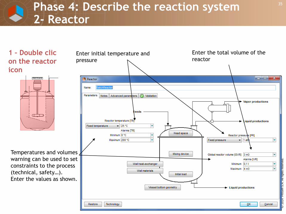
Temperatures and volumes
warning can be used to set
constraints to the process
(technical, safety…).
Enter the values as shown.
Enter the total volume of the
reactor Enter initial temperature and
pressure
1 – Double clic
on the reactor
icon
Phase 4: Describe the reaction system 2- Reactor

© 2
014
Pro
Sim
S.A
. A
ll rights
reserv
ed
.
36
Click on “Initial
load”
Enter composition and mass
of the initial load
Phase 4: Describe the reaction system 2- Reactor

© 2
014
Pro
Sim
S.A
. A
ll rights
reserv
ed
.
37
Click on “Wall heat
exchanger”
Enter layout, jacket characteristics
and geometrical parameters
Phase 4: Describe the reaction system 2- Reactor

© 2
014
Pro
Sim
S.A
. A
ll rights
reserv
ed
.
38
Click on “Wall materials”
Enter wall materials characteristics.
One or two material types could be selected
Phase 4: Describe the reaction system 2- Reactor

© 2
014
Pro
Sim
S.A
. A
ll rights
reserv
ed
.
39
Click on “Vessel bottom
geometry”
Enter vessel bottom characteristics
Phase 4: Describe the reaction system 2- Reactor

© 2
014
Pro
Sim
S.A
. A
ll rights
reserv
ed
.
40
Select the validation tab.
This tab indicates warning messages. If the data are
correctly entered, this tab should be empty and the
reactor icon is not highlighted anymore.
Phase 4: Describe the reaction system 2- Reactor
© 2
014
Pro
Sim
S.A
. A
ll rights
reserv
ed
.
41
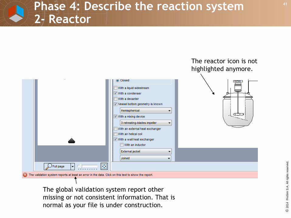
The reactor icon is not
highlighted anymore.
The global validation system report other
missing or not consistent information. That is
normal as your file is under construction.
Phase 4: Describe the reaction system 2- Reactor

© 2
014
Pro
Sim
S.A
. A
ll rights
reserv
ed
.
42
Double click on “Condenser”
Enter the number of stages.Two condensers in serie can be defined
Phase 4: Describe the reaction system 3- Condenser

© 2
014
Pro
Sim
S.A
. A
ll rights
reserv
ed
.
43
Double click on a tank1 - Enter the name of the gas tank
2- Enter the name of the liquid tank
Phase 4: Describe the reaction system 4- Products tanks

© 2
014
Pro
Sim
S.A
. A
ll rights
reserv
ed
.
44
The description of the reactor
operations is made in the scenario
window by a succession of steps and
events.
Phase 5: Describe the operating steps

© 2
014
Pro
Sim
S.A
. A
ll rights
reserv
ed
.
45
1- Click on “Variable heat duty” step. 2- Click on the scenario window
A new step and a new event will be created
Phase 5: Describe the operating steps

© 2
014
Pro
Sim
S.A
. A
ll rights
reserv
ed
.
46
1- Click on “connection”.
2- Click on the first triangle (operation start) and then
click on the first step
A new connection will be created
Phase 5: Describe the operating steps
© 2
014
Pro
Sim
S.A
. A
ll rights
reserv
ed
.
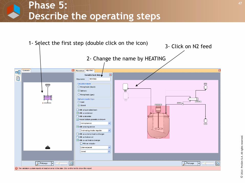
47
1- Select the first step (double click on the icon)
2- Change the name by HEATING
3- Click on N2 feed
Phase 5: Describe the operating steps

© 2
014
Pro
Sim
S.A
. A
ll rights
reserv
ed
.
48
1- Select “Feed is open”
2- Enter operating parameters during
the first step:
• Temperature
• Pressure
• Feed composition
• Total mass flowrate
3- Click on OK
Phase 5: Describe the operating steps

© 2
014
Pro
Sim
S.A
. A
ll rights
reserv
ed
.
49
1- Select “Condenser is open”
3- Enter operating parameters
for the condensing first stage
during the first step:
•Calculation type
•Exchange coefficient
•Exchange area
•Pressure drop
•Fluid type
•Inlet temperature
•Mass flowrate
2- Select “Calculated
condenser”
and select 2 stages
Double click on the condenser to access to the detail view
Phase 5: Describe the operating steps

© 2
014
Pro
Sim
S.A
. A
ll rights
reserv
ed
.
50
1- Enter operating parameters for
the second condensing stage
During the first step:
•Calculation type
•Exchange coefficient
•Exchange area
•Pressure drop
•Fluid type
•Inlet temperature
•Mass flowrate
2- Click on OK
Click on the 2nd stage
Phase 5: Describe the operating steps

© 2
014
Pro
Sim
S.A
. A
ll rights
reserv
ed
.
51
1- Double click on the reactor
icon on the HEATING flow
scheme to enter in this view
2- Enter operating
parameters:
• reflux percentage
(1 for total reflux)
•Pressure specification
3- Click on
“Mixing parameters”
Phase 5: Describe the operating steps

© 2
014
Pro
Sim
S.A
. A
ll rights
reserv
ed
.
52
Enter mixing operating parameter
during the first step:
• Rotation speed
Phase 5: Describe the operating steps

© 2
014
Pro
Sim
S.A
. A
ll rights
reserv
ed
.
53
2- Enter operating parameters:
• Fluid type
• Mass flowrate
• Pressure
Click on “Wall heat exchanger” to enter the detail view and
set the
heating operating parameters during this step
1- Select “the wall heat exchanger is in use”
Phase 5: Describe the operating steps

© 2
014
Pro
Sim
S.A
. A
ll rights
reserv
ed
.
54
2- Enter event
type and value
Click on the HEATING step ending event
1- Enter the name
of the event
Phase 5: Describe the operating steps
© 2
014
Pro
Sim
S.A
. A
ll rights
reserv
ed
.
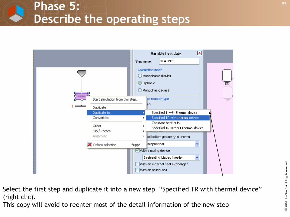
55
Select the first step and duplicate it into a new step “Specified TR with thermal device”
(right clic).
This copy will avoid to reenter most of the detail information of the new step
Phase 5: Describe the operating steps

© 2
014
Pro
Sim
S.A
. A
ll rights
reserv
ed
.
56
Connect appropriately the new step to the ending event of the HEATING step
and to the final simulation event
Phase 5: Describe the operating steps

© 2
014
Pro
Sim
S.A
. A
ll rights
reserv
ed
.
57
2- Enter the feed operating
parameters during the second step:
• Temperature
• Pressure
• Feed composition
• Mass flowrate
1- Select “Feed is open”
3- Click on OK
Double click on the feed Cl2
Phase 5: Describe the operating steps

© 2
014
Pro
Sim
S.A
. A
ll rights
reserv
ed
.
58
2- Select “PID”
3- Enter temperature
set point, minimum and
maximum
5- Click on PID to enter the
detail view
4- Enter minimum
and maximum flowrate
1- Double click on the reactor
icon
Phase 5: Describe the operating steps

© 2
014
Pro
Sim
S.A
. A
ll rights
reserv
ed
.
59
1- Enter controller parameters
2- Enter valve parameters
3- Click on “OK”
Phase 5: Describe the operating steps
© 2
014
Pro
Sim
S.A
. A
ll rights
reserv
ed
.
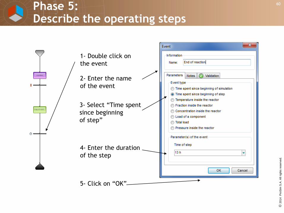
60
1- Double click on
the event
3- Select “Time spent
since beginning
of step”
5- Click on “OK”
4- Enter the duration
of the step
2- Enter the name
of the event
Phase 5: Describe the operating steps
© 2
014
Pro
Sim
S.A
. A
ll rights
reserv
ed
.
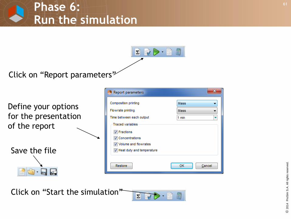
61
Define your options
for the presentation
of the report
Click on “Report parameters”
Click on “Start the simulation”
Save the file
Phase 6: Run the simulation

© 2
014
Pro
Sim
S.A
. A
ll rights
reserv
ed
.
62
You can hold the simulation to review the evolution of the different parameters
Phase 6: Run the simulation

© 2
014
Pro
Sim
S.A
. A
ll rights
reserv
ed
.
63
When simulation is completed, click on « Results »
to display the simulation results
Phase 6: Run the simulation
© 2
014
Pro
Sim
S.A
. A
ll rights
reserv
ed
.
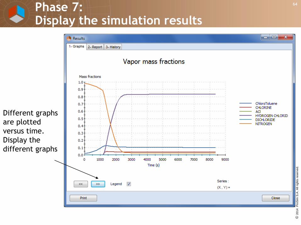
64
Different graphs
are plotted
versus time.
Display the
different graphs
Phase 7: Display the simulation results

© 2
014
Pro
Sim
S.A
. A
ll rights
reserv
ed
.
65
Access to the report
and review:
- reactor characteristics
- mass and energy
balance versus time for
each operating step
- mass balance at the
end of each step
Phase 7: Display the simulation results

© 2
014
Pro
Sim
S.A
. A
ll rights
reserv
ed
.
66
ProSim SA
51, rue Ampère
Immeuble Stratège A
F-31670 Labège Cedex
France
Phone: +33 (0) 5 62 88 24 30
ProSim, Inc.
325 Chestnut Street, Suite 800
Philadelphia, PA 19106
U.S.A.
Phone: +1 215 600 3760www.prosim.net