getting started tutorial - ige+xao · this document is intended for anybody who is new to see...
TRANSCRIPT

Tutorial
COPYRIGHT © 2017 IGE+XAO. All rights reserved
Getting Started Tutorial
V8R2

Tutorial
COPYRIGHT © 2017 IGE+XAO. All rights reserved
Page 2 A. Foreword
Copyright Copyright (c) September 2017 IGE-XAO. All rights reserved. No part of this manual, or any portion of it, shall be reproduced, transcribed, saved or translated, under whatever form and by whatever means, without written authorization from IGE-XAO USA, 2540 King Arthur Blvd. Suite 209-M, Lewisville, TX 75056.

Tutorial
COPYRIGHT © 2017 IGE+XAO. All rights reserved
A. Foreword Page 3
TABLE OF CONTENTS
GETTING STARTED TUTORIAL 1
A FOREWORD 5
B BEFORE YOU START 6
B.1. ABBREVIATIONS USED IN THIS TUTORIAL 6 B.2. FOLDERS AND FILES 7
C CREATING A WORKSPACE 8
C.1. CREATING A NEW WORKSPACE 8
D DRAWING CIRCUIT DIAGRAMS 12
D.1. DRAWING PAGE 1 12 D.1.1. Potentials on Page 1 12 D.1.2. Electrical Symbols on Page 1 13 D.1.3. Inserting a Protective Device on Page 1 15 D.1.4. Inserting a Circuit Breaker on Page 1 15 D.1.5. Inserting a Motor on Page 1 16 D.1.6. Inserting Type and Description 17 D.1.7. Inserting Main Contacts on Page 1 18 D.1.8. Inserting a Terminal Strip with 5 Terminals on Page 1 20 D.1.9. Inserting a Terminal Strip with 4 Terminals on Page 1 21 D.1.10. Connecting Symbols on Page 1 22 D.1.11. Inserting a Relay Coil on Page 1 25 D.1.12. Connecting the Relay Coil on Page 1 26 D.1.13. Inserting a Circuit Breaker in a Connection on Page 1 27 D.1.14. Inserting a Break Contact on Page 1 28 D.1.15. Copying a Row on Page 1 29 D.1.16. Inserting a Lamp on Page 1 30 D.1.17. Inserting a Relay Contact on Page 1 31 D.1.18. Inserting Terminals on Page 1 32 D.1.19. Drawing a Cable on Page 1 33 D.1.20. Page 1 Illustrated 35
D.2. DRAWING PAGE 2 35 D.2.1. Creating Page 2 35 D.2.2. Showing Two Pages Simultaneously 37 D.2.3. Copying Potentials 37 D.2.4. Restoring the Window of Page 2 38 D.2.5. Electrical Symbols on Page 2 38 D.2.6. Inserting Fuses on Page 2 39 D.2.7. Inserting a Contactor on Page 2 39 D.2.8. Inserting a Motor on Page 2 41 D.2.9. Connecting Symbols on Page 2 43 D.2.10. Inserting Terminal Strips on Page 2 45 D.2.11. Inserting Relay Coils on Page 2 47 D.2.12. Connecting the Relay Coil on Page 2 48 D.2.13. Inserting Circuit Breakers on Page 2 48 D.2.14. Inserting Contacts NC on Page 2 49 D.2.15. Inserting Contacts NO on Page 2 51 D.2.16. Drawing Wires on Page 2 52

Tutorial
COPYRIGHT © 2017 IGE+XAO. All rights reserved
Page 4 A. Foreword
D.2.17. Drawing a Cable on Page 2 54 D.2.18. Page 2 Illustrated 57
E ADDITIONAL PROCESSING OF CIRCUIT DIAGRAMS 58
E.1. PAGE INDEX 58 E.2. TEXTS 59
F PRINTING 63
F.1. PRINT 63 F.2. PRINT PREVIEW 64
G CLOSING REMARKS 65

Tutorial
COPYRIGHT © 2017 IGE+XAO. All rights reserved
A. Foreword Page 5
A FOREWORD This document is intended for anybody who is new to SEE Electrical Free. This will encompass users who already have experience in using electrical drawing packages, and also those who are totally new to the area. In addition, it is understood that readers will also have very different levels of IT literacy. Because of this, the instructions have been made as complete as possible. If you feel some of the steps are ‘a bit basic’, then please feel free to skip through them in quick time. The tutorial is best carried out with the use of a mouse, as a laptop touchpad lacks the precision required for quickly and accurately placing components. Steps involving ‘clicking’ or ‘selecting’ should be taken to imply that the left mouse button is to be used. The right mouse button is used less, and you will be specifically instructed when to do so. It is strongly recommended that you fully read each step before carrying out its instructions. You are also encouraged to always compare what you have drawn to the relevant figures, as these are the best indication that what you have done is correct. You will quickly become familiar with the various functions and how to implement them. Indeed, one of the major strengths of SEE Electrical over other Electrical CAD (ECAD) packages is its ease of use. Only a minimal training period is required before users can quickly create their own complex projects.

Tutorial
COPYRIGHT © 2017 IGE+XAO. All rights reserved
Page 6 B. Before You Start
B BEFORE YOU START
It is essential that you follow the instructions on this page before starting the tutorial; otherwise, you will not have the required symbol groups available to you in SEE Electrical.
It is assumed that you have downloaded the free version of SEE Electrical from our website. It is also assumed that you have installed the software on your computer. If this is not the case, then do this before continuing. If you need help with any of the above, please contact our helpdesk.
B.1. ABBREVIATIONS USED IN THIS TUTORIAL Inputs are described as follows:
CA Select a category CO Select a command + Select an element with the cursor M Select from a pull-down menu # Keyboard entry > Select a field in a window <Input> Type text or select an element etc. T Click onto a tab in a window I Select a toolbar icon

Tutorial
COPYRIGHT © 2017 IGE+XAO. All rights reserved
B. Before You Start Page 7
B.2. FOLDERS AND FILES SEE Electrical uses the following folders and files:
< SEE Electrical V8R2 folder> The program files of SEE Electrical are saved in this folder.
Users\Public\Public Documents\IGE-XAO\SEE Electrical Free\ V8R2\ Projects
In this folder, you can find the workspace files of SEE Electrical delivered by default.
Workspace files have the .SEP extension.
Users\Public\Public Documents\IGE-XAO\SEE Electrical Free\ V8R2\Symbols
This folder contains the symbol databases in SEE Electrical.
Symbol databases have the .SES extension.
The TYPES.SES database, required in the Standard and Advanced levels is also stored here. (not available in SEE Electrical Free)
Note that the SYSTEM.SES library is required for internal purposes and must not be removed from this folder.
Users\Public\Public Documents\IGE-XAO\SEE Electrical Free\ V8R2\Templates
This folder contains workspace and page templates and templates for lists and labels. Fonts are saved here, too.
SEP: Workspace templates
TDW: Page templates
DAT: Fonts
Users\Public\Public Documents\IGE-XAO\SEE Electrical Free\ V8R2\Templates\Label_Settings
SLS files (used for creating labels for different printer formats).

Tutorial
COPYRIGHT © 2017 IGE+XAO. All rights reserved
Page 8 C. Creating a Workspace
C CREATING A WORKSPACE
Important: Do not begin this stage before you have followed the instructions on the previous pages!
C.1. CREATING A NEW WORKSPACE This chapter shows you how to create a new workspace and then create a page in it. Quick guide: 1.CA File 2.CO New…
The New Workspace dialogue box is displayed.
Note:
Various contents may appear within the dialogue.
3.> File name 4.# <Workspace name>
You can write a long descriptive name which can contain spaces. 5.> Save
The Select Workspace Template window, which contains a list of available workspace templates, is displayed:

Tutorial
COPYRIGHT © 2017 IGE+XAO. All rights reserved
C. Creating a Workspace Page 9
Note
Various contents may appear within the window.
6.> IEEE, Consecutive Numbering by Page, B-Size, 1 Zone 7.> OK
The workspace information is displayed in the Properties pane in the left area of the main SEE Electrical window:
In the first field you can see the name of the workspace (*.SEP). In these fields you can type in text information applicable to the whole project. If text placeholders are defined in the page templates of the circuit diagrams, the information is transferred on all the pages of the workspace. Consequently, here you must enter or change all the data that must appear on all pages. Customer Information You can type information concerning the customer in the fields "Customer", "Address 1", etc... General Information about the workspace In the fields "Workspace Description-line 01 … 10", you can type descriptions of the project. These descriptions will automatically be inserted into all the pages of the workspace if the respective placeholders are available in the page template. In this workspace example and in the relevant page template, description lines 01 and 02 are used to describe the workspace.

Tutorial
COPYRIGHT © 2017 IGE+XAO. All rights reserved
Page 10 C. Creating a Workspace
Type in the following text in the dialogue: 8.> Workspace Description-line 01: 9.# Workspace example 10.> Workspace Description-line 02: 11.# SEE Electrical
Fill information about the customer if desired. The new workspace has been created. Now you will create the first page in it.
12. Right-click the module in the Workspace Explorer and select the New Page pop-up command.
The Page information dialogue box is displayed. Type the following information in the dialogue box: 13.> Page 14.# 1
The page number is automatically suggested by SEE Electrical but you can change it.
15.> Page Description-line 01 The data entered in the Page information dialogue box applies only to the current page of the circuit diagram. It will be displayed in the page if the corresponding text placeholders are available in the page template.
16.# Power Supply 17.> Page Description-line 02 18.# Motor Control 19.> Page Description-line 03: 20.# Motor Reverse 21.> Page Created Date 22.# SEE Electrical automatically inserts the date but this can be changed if desired.
If you click the field in the "Page Created Date" field, you can choose a date.
You can change the date by clicking the field in the "Page Created Date" field. You can change the day, month, or year.

Tutorial
COPYRIGHT © 2017 IGE+XAO. All rights reserved
C. Creating a Workspace Page 11
23.> OK
Page 1 is now displayed on the screen:
Hints for creating a new page
Diagrams in ISO A3 format are used for circuit diagrams by default. The page dimensions and the standard sheet are defined by the workspace template or page template that you choose. For example, in this workspace example, you have chosen the workspace template IEEE, Consecutive Numbering by Page, B-Size, 1 Zone. You can create your own templates and standard sheets.

Tutorial
COPYRIGHT © 2017 IGE+XAO. All rights reserved
Page 12 D. Drawing Circuit Diagrams
D DRAWING CIRCUIT DIAGRAMS
D.1. DRAWING PAGE 1 This chapter shows you, step by step, how to draw the circuit diagram on page 1.
D.1.1. POTENTIALS ON PAGE 1 Follow the next steps to insert five potentials on page 1. First, insert the three top potentials. Quick guide: 1.CA Electrical IEEE 2.CO Left (Potential panel)
Click the command. The potential is drawn and the Component Properties dialogue box is displayed. Type the name of the potential.
3.# Type L1 in the “Product (-)” field 4.> OK 5.CA Electrical IEEE 6.CO Left 7.# Type L2 in the “Product (-)” field 8.> OK 9.CA Electrical IEEE 10.CO Left 11.# Type L3 in the “Product (-)” field 12.> OK
Hint
You can activate the Potential – Left functionality by pressing F11 instead of clicking the icon.
In the next steps, insert the two bottom potentials. Quick guide: 1.CA Electrical IEEE 2.CO Right (Potential panel) 3.# Type PE in the “Product (-)” field 4.> OK 5.CA Electrical IEEE 6.CO Right (Potential panel) 7.# Type N in the “Product (-)” field 8.> OK

Tutorial
COPYRIGHT © 2017 IGE+XAO. All rights reserved
D. Drawing Circuit Diagrams Page 13
Hint
You can activate the Potential – Right functionality by pressing F12 instead of clicking the icon.
Hint
All wires must be continuous lines. This also applies to PE and N.
D.1.2. ELECTRICAL SYMBOLS ON PAGE 1 You will now insert electrical symbols in the circuit diagram.
In the left area of the workspace, click the Symbols tab, as shown below:
The symbol tree is displayed:

Tutorial
COPYRIGHT © 2017 IGE+XAO. All rights reserved
Page 14 D. Drawing Circuit Diagrams
Note:
Various contents may appear within the panel depending on the installed symbol libraries.
Selecting a symbol database SEE Electrical symbols are distributed into symbol databases. There exists a database of graphical symbols for diagrams according to IEEE Std 91/91a and IEEE Std 315. Other symbol databases include symbols for the layout of switchboards from Danfoss, Siemens, etc.
▪ Select the database that contains the symbols you wish to work with. (In this case, select Electrical & Automation IEEE v2.)
▪ Double-click the Electrical & Automation IEEE v2 symbol database or click on the plus sign on the left of the symbol database name to expand it.
If the symbol database is not visible, browse through the symbol tree. Each symbol database is divided into different folders such as relay coils, converters and motors. The different symbol folders are displayed. The symbol folders are arranged in alphabetical order:
▪ Select the folder for the specific symbol you wish to work with. ▪ Select the symbol and insert it in the circuit diagram.

Tutorial
COPYRIGHT © 2017 IGE+XAO. All rights reserved
D. Drawing Circuit Diagrams Page 15
D.1.3. INSERTING A PROTECTIVE DEVICE ON PAGE 1
You will now insert a protective device in column 1.
Quick guide: 1. Double-click the Circuit Breaker symbol folder to open it. 2.+ Click the TCB3P symbol.
Once you have selected the symbol, it appears attached to the cursor. 3.+ Move the cursor into the drawing area (Cell E1) where you want to insert the symbol. 4.+ Click with the mouse to insert the symbol. 5. The symbol name is automatically assigned (1CB1). 6. Right-click to exit the insertion mode.
Hint
If you cannot find the symbol in your symbol database, use the "Filter" field in the upper part of the panel. Type "TCB3P" in it and press Enter.
D.1.4. INSERTING A CIRCUIT BREAKER ON PAGE 1 You will now insert a circuit breaker in column 2. Quick guide: 1. Double-click the Circuit Breaker symbol folder to open it. 2. Click the CB3P symbol. 3.+ Move the cursor into the drawing area where you want to insert the symbol (the
symbol is attached to the cursor). 4.+ Click to insert the symbol between cells B3 and C3.

Tutorial
COPYRIGHT © 2017 IGE+XAO. All rights reserved
Page 16 D. Drawing Circuit Diagrams
5. Right-click to exit the insertion mode.
Hint
You can close a symbol folder by clicking on the minus sign on the left of the symbol folder:
D.1.5. INSERTING A MOTOR ON PAGE 1 You will now insert a motor in column 9, behind the right potentials.
Quick guide: 1. Open the Motors symbol folder. 2. Select the Motor_Gnd symbol (this is a 3 phase motor with additional ground
contact). 3.+ Move the cursor into the drawing area on the right of the potentials N and PE.

Tutorial
COPYRIGHT © 2017 IGE+XAO. All rights reserved
D. Drawing Circuit Diagrams Page 17
4.+ Click to insert the symbol. Position the motor accurately, so its contacts are aligned
with the contacts of the 1CB1 protective device. 5. Right-click to exit the insertion mode.
D.1.6. INSERTING TYPE AND DESCRIPTION You will now insert data about the type and possibly, the function of the three symbols. Quick guide: 1.+ Double-click the 1CB1 protective device symbol.
The symbol is highlighted in red. The Component Properties dialogue box is displayed.
2.> Product (-) The component name is displayed, and you can change it as desired.
3.> Type 4.# 3VE
This is an example of a type.

Tutorial
COPYRIGHT © 2017 IGE+XAO. All rights reserved
Page 18 D. Drawing Circuit Diagrams
5.> Connection 00, etc.
The connection texts of the component are displayed in these fields. You can change them if required.
6.> OK Click OK to close the Component Properties dialogue.
Change also the types of the motor and the main circuit breaker. The main circuit breaker must receive the type "S3", and the motor - the type "M10". You must also change the connection names of the motor in its Component Properties dialogue:
D.1.7. INSERTING MAIN CONTACTS ON PAGE 1 You will now insert main contacts in columns 3 and 4. Quick guide: 1. Double-click the Contactor symbol folder to open it. 2. Select the CON3P Slave contactor symbol. 3.+ Move the cursor into the drawing area. 4.+ Insert the symbol right below the main circuit breaker aligned with the 1CB1
protective device. The Component Properties dialogue box is displayed. Change the name of the contact.
5.> Product (-) 6.# K1 7.# Fill in the empty fields as shown in the picture:

Tutorial
COPYRIGHT © 2017 IGE+XAO. All rights reserved
D. Drawing Circuit Diagrams Page 19
8.> OK
Insert the second main contact. 9.+ Click to insert the contact symbol below the first contact.
The Component Properties dialogue box is displayed again. 10.> Product (-) 11.# K2 12.# Enter the connection numbers again. 13.> OK
Right-click to exit the insertion mode.

Tutorial
COPYRIGHT © 2017 IGE+XAO. All rights reserved
Page 20 D. Drawing Circuit Diagrams
D.1.8. INSERTING A TERMINAL STRIP WITH 5 TERMINALS ON PAGE 1
You will now insert five terminals in column 8 on the right of the existing potentials.
Note:
To insert the terminals, you will need more space. Move the two right potentials by selecting both of them and dragging them three-four steps to the left
Quick guide: 1. Open the Terminals symbol folder. 2. Select the TER S1 2C symbol. 3.+ Move the cursor into the drawing area where you want to insert the symbol. The
symbol is attached to the cursor. 4.+ Click to insert the symbol (in Cell B8). The terminal must be aligned with the circuit
breaker’s first contact. The Component Properties dialogue box is displayed (first terminal), change as described:
5.> Product (-) 6.# TB1 7.> Terminal Number 8.# 1 (first terminal number available in the terminal strip) 9.> OK 10. Continue inserting terminals. Insert four more terminals aligned with the circuit
breaker’s contacts.
Hint
Hold down the CTRL key to copy the first terminal to the next connections. This way you copy the "Product (-)" name of the terminal, so you do not have to enter it every time.
The numbers 2, 3, 4 and 5 are assigned automatically to the next four terminals (if you choose not to copy the first terminal, type "TB1" in the "Product (-)" fields of the respective Component Properties dialogues).

Tutorial
COPYRIGHT © 2017 IGE+XAO. All rights reserved
D. Drawing Circuit Diagrams Page 21
D.1.9. INSERTING A TERMINAL STRIP WITH 4 TERMINALS ON PAGE 1 You will now insert four terminals in column 8 right below the first five terminals.
Quick guide: 1. The Terminals symbol folder is open. 2. Select the TER S1 2C symbol. 3.+ Select the place on the page where you want to insert the terminal strip (the symbol is
attached to the cursor). 4.+ Click to insert the symbol (in Cell D8). The terminal must be aligned with the motor’s
connections. The Component Properties dialogue box is displayed (first terminal), change as described:
5.> Product (-) 6.# TB1 7.> Terminal Number 8.# 6
Terminal number 6 is suggested. Accept it. 9.> Terminal Sorting 10.# 6
Terminal index 6 is suggested. Accept it. 11.> OK

Tutorial
COPYRIGHT © 2017 IGE+XAO. All rights reserved
Page 22 D. Drawing Circuit Diagrams
Right-click to exit the insertion mode.
12. Insert three more terminals aligned with the motor’s connections. The numbers 7, 8 and 9 are assigned automatically to the next three terminals (if you choose not to copy the first terminal, type "TB1" in the "Product (-)" fields of the respective Component Properties dialogues). Move the potentials, if necessary, so there is enough place for all components.
D.1.10. CONNECTING SYMBOLS ON PAGE 1 You will now connect the inserted symbols with each other and with the potentials.
Attention!
You must draw wires and not lines because wires are regarded by SEE Electrical as real electrical connections but lines are not.
First, you will draw a 3 wires connection between the potentials L1, L2 and L3 and the terminals TB1:1, TB1:2 and TB1:3.

Tutorial
COPYRIGHT © 2017 IGE+XAO. All rights reserved
D. Drawing Circuit Diagrams Page 23
Quick guide: 1.CA Electrical IEEE 2.CO 3 Wires (Wire Connections panel) 3.+ Select the starting point of the wire on the potential L1 strictly aligned with terminal
TB1:1 by clicking the left mouse button. 4.+ Select the second point of the wire by clicking the right connection of terminal TB1:1. In addition to the connection between L1 and TB1:1, SEE Electrical draws automatically two more connections: between the potential L2 and terminal TB1:2, and between the potential L3 and terminal TB1:3. The connections are automatically broken at the symbol places (for example, at the main circuit breaker). If the components are not aligned, drag them to the desired place. Now you will draw a 3 wires connection between the potentials L1, L2 and L3 and the motor. Quick guide: 1. The 3 Wires command is still active. Keep on drawing. 2.+ Click to select the starting point of the wire on the potential L1 strictly aligned with
terminal TB1:6 and motor connection U1. 3.+ Select the second point of the wire on connection U1 of the motor. Now you will connect terminal TB1:4 with the potential N, and terminal TB1:5 as well as the motor connection PE with the potential PE. Quick guide: 1.CA Electrical IEEE 2.CO 1 Wire (Wire Connections panel) 3.+ Select the starting point of the wire on the potential N aligned with the terminal TB1:4
by clicking the left mouse button. 4.+ Select the second point of the wire on the left connection of terminal TB1:4 by clicking
the left mouse button again. 5. The 1 Wire command is still active. Now, draw the wire between the potential PE and
the left connection of terminal TB1:5, as described above. 6. The 1 Wire command is still active. Draw the wire between the potential PE and the
motor connection PE. Right-click to exit the wire drawing mode.
Hint
You can activate the 3 Wires functionality by using the CTRL + 3 key combination, and you can activate the 1 Wire functionality by using the CTRL + 1 key combination.

Tutorial
COPYRIGHT © 2017 IGE+XAO. All rights reserved
Page 24 D. Drawing Circuit Diagrams
Wires for reversal of rotation direction
You will now draw connections from the horizontal wires in rows D and E, through the three-pole contactor in rows F and G, and back to the horizontal wires in rows D and E.

Tutorial
COPYRIGHT © 2017 IGE+XAO. All rights reserved
D. Drawing Circuit Diagrams Page 25
Quick guide: You can draw the wires by using the 1 Wire command. 1.CA Electrical IEEE 2.CO 1 Wire (Wire Connections panel) 3.+ Select the starting point of the wire on the horizontal wire on the left of K1/ connection
1. 4.+ Move the cursor down until aligned with connection 1 of K2 of the main relay-contact,
and click to set a corner point. 5.+ Go horizontally to the right of connection 2 of K2 and click to create the second corner
point. 6.+ Complete the wire creation by clicking on the right of connection point 6 of K1. 7.+ Repeat the process for the other connection points: K1/5 through K2/5/6 to K1/2 and
K1/3 through K2/3/4 to K1/4. Right-click to exit the wire drawing mode.
D.1.11. INSERTING A RELAY COIL ON PAGE 1 You will now insert a relay coil in column 6 on page 1.
Quick guide: 1. Open the Relay symbol folder from Electrical & Automation IEEE. 2. Select the Coil symbol. 3. Select where on the page you want to insert the relay coil (the symbol is attached to
the cursor). 4.+ Click with the left mouse button to insert the symbol (cell H6).
Right-click to exit the insertion mode. Changing the relay coil type: Quick guide: 1.+ Double-click the relay coil.
The symbol is highlighted in red. The Component Properties dialogue box is displayed.
2.> Product (-) 3.# K1 4. Type 5.# 3TB4011
This is an example of a type.

Tutorial
COPYRIGHT © 2017 IGE+XAO. All rights reserved
Page 26 D. Drawing Circuit Diagrams
6.> OK
A contact cross appears automatically on the right of the potentials, displaying the main references of the existing relay-contacts. If, later on, you assign additional contacts to the relay coil, their corresponding references are automatically added in the contact cross.
Hint
The relay coils and the assigned contacts are displayed in the list of contacts. Using the list of contacts, you can easily recognize contacts not assigned to coils and vice versa. For example, you have drawn a contact NO named 1K5 in the circuit diagram, but you have not inserted a relay coil with the same name. You will see the contact NO in the list of contacts but a coil is not shown above.
D.1.12. CONNECTING THE RELAY COIL ON PAGE 1 You will now connect the relay coil K1 with the potentials L3 and N. Quick guide: 1.CA Electrical IEEE 2.CO 1 Wire (Wire Connections panel) 3.+ Select the starting point of the wire on the potential L3 strictly aligned with the relay
coil’s connections. 4.+ Finish the wire on potential N.
The connection is cut at the relay coil. The nodes at the potentials appear automatically. Right-click to exit the wire drawing mode.

Tutorial
COPYRIGHT © 2017 IGE+XAO. All rights reserved
D. Drawing Circuit Diagrams Page 27
D.1.13. INSERTING A CIRCUIT BREAKER IN A CONNECTION ON PAGE 1 So far, you have inserted symbols and connected them with wires. You will now try to insert symbols on existing wires. Every time you insert a symbol on a wire, the wire will be automatically cut and the symbol will be connected correctly.
Hint
If SEE Electrical does not cut the wire or cable when you insert a symbol, this means that you have used by mistake an ordinary line instead of a wire to connect your symbols.
You will now insert a push button in column 3 on the existing wire.

Tutorial
COPYRIGHT © 2017 IGE+XAO. All rights reserved
Page 28 D. Drawing Circuit Diagrams
Quick guide: 1. Open the Push Button symbol folder in Electrical & Automation IEEE v2 library. 2. Select the Push Button Contact NO symbol. 3.+ Select the place where you want to insert the switch (the symbol is attached to the
cursor). 4.+ Click to insert the symbol on the wire which connects the coil in cell H3. 5.> Product (-) 6.# S1 7.> Type 8.# TPS
This is an example of a type. 9.> OK 10. Right-click to exit the wire insertion mode.
D.1.14. INSERTING A BREAK CONTACT ON PAGE 1 You will now insert the break contact symbol in column 5.
Quick guide: 1. Open the Relay symbol folder in Electrical & Automation IEEE library. 2. Select the Contact NC symbol. 3.+ Select the place in the drawing area where you want to insert the symbol (the symbol
is attached to the cursor). 4.+ Click the left mouse button to insert the symbol (on the right of the push button - in
cell H5, for example). SEE Electrical opens automatically the Component Properties dialogue box. Assign the contact to a relay coil.
5.> Product (-) 6.# K2 (the relay coil will be created in row I). 7.> Connection 00 8.# 21
Enter the contact number of the connection. 9.> Connection 01 10.# 22
Enter the contact number of the second connection. 11.> OK
Right-click to exit the insertion mode.

Tutorial
COPYRIGHT © 2017 IGE+XAO. All rights reserved
D. Drawing Circuit Diagrams Page 29
D.1.15. COPYING A ROW ON PAGE 1
You have now drawn all the elements in Row H. Row I will be exactly like Row H, but the component names of the symbols will be changed. Therefore, it is easier to copy everything from Row H to Row I. There are several ways of copying but the easiest one is described below. Quick guide: You must select all the symbols in Row H within a frame as shown below:
1.+ Select the first point of the frame by clicking with the mouse at the top left corner of
the frame. 2.+ Keep the left mouse button pressed and drag, so that all the symbols available in row
H are included in the frame. 3.+ Release the left mouse button when you reach the bottom right corner of the frame. 4. The selected symbols are highlighted in red. 5. Move the cursor near to the top node. Click the wire and hold down the left mouse
button while moving the group. The selected symbols and wires are attached to the cursor. The point attached to the cursor is the point where the cursor was placed at the beginning of this step.
6. Move the group to the position where you want to insert it (Row I). 7.+ Press and hold down the CTRL key (Windows standard procedure: Copy while
moving) when releasing the left mouse button to place the group. The group is copied to Row I.
8.# Type S2 in the "Product (-)" field and TPS in the "Type" field for the new push button.

Tutorial
COPYRIGHT © 2017 IGE+XAO. All rights reserved
Page 30 D. Drawing Circuit Diagrams
9.# Type K1 in the "Product (-)" field for the new contact. The contact is assigned to relay coil K1. 10.# Type K2 in the "Product (-)" field for the new coil.
The cross-references in the contact cross of the relay coil are automatically updated. Row I is now an exact copy of Row H.
D.1.16. INSERTING A LAMP ON PAGE 1 You will now insert a lamp in Row I column 6.
Quick guide: 1. Open the Lamps / Lights / Indicators symbol folder. 2. Select the Pilot Light symbol. 3.+ Select the place where you want to insert the lamp (the symbol is attached to the
cursor). 4.+ Click the left mouse button to insert the symbol below the K2 coil.
Right-click to exit the insertion mode. Changing the type of the lamp: Quick guide: 1.+ Double-click the lamp.
The symbol is highlighted in red. The Component Properties dialogue box is displayed.
2.> Type 3.# ZLA558
This is an example of a type. 4.> OK

Tutorial
COPYRIGHT © 2017 IGE+XAO. All rights reserved
D. Drawing Circuit Diagrams Page 31
D.1.17. INSERTING A RELAY CONTACT ON PAGE 1
You will now insert a NO relay-contact in column 5.
Quick guide: 1. Double-click the Relay symbol folder. 2. Select the Contact NO symbol by clicking the left mouse button. 3.+ Select the place where you want to insert the symbol (the symbol is attached to the
cursor). 4.+ Click the left mouse button to insert the symbol. The contact must be aligned with the
lamp’s connections. 5. In the dialogue box, assign the contact to the appropriate relay coil. 6.> Product (-) 7.# K1
This symbol is only applied when associated with a relay coil. You must insert manually the numbers of the connection text. For example:
8.> Connection 00 9.# 13
Type in the contact number of the first connection. 10.> Connection 01 11.# 14
Type in the contact number of the second connection. 12.> OK
Right-click to exit the insertion mode. Drawing a wire in row I Now you will connect the potentials L3 and N together in row I. Quick guide: 1.CA Electrical IEEE 2.CO 1 Wire (Wire Connections panel) 3.+ Select the starting point of the wire on the potential L3 strictly aligned with the lamp
and the contact. 4.+ Finish the wire on potential N.
The connection is cut at the lamp as well as at the relay contact NO. The nodes at the potentials appear automatically. Right-click to exit the wire drawing mode.

Tutorial
COPYRIGHT © 2017 IGE+XAO. All rights reserved
Page 32 D. Drawing Circuit Diagrams
D.1.18. INSERTING TERMINALS ON PAGE 1
You will now insert four terminals in Row H and Row I.
Quick guide: 1. Open the Terminals symbol folder from Electrical & Automation IEEE v2 library. 2. Select the TER S1 2C symbol. 3.+ Select the place where you want to insert the terminal TB2 (at the start of row H, the
symbol is attached to the cursor). 4.+ Click the left mouse button to insert the symbol.
The Component Properties dialogue box is displayed. Type in the following data:
5.> Product (-) 6.# TB2 7.> Terminal Number 8.# 1 (the first number available in the terminal strip) 9.> Terminal Sorting
The terminal index is used to sort the terminals in the list of terminals. 10.# 1
You can enter a type in the "Type" field. 11.> OK 12.+ Insert the terminal TB2 (in row H, after the relay coil). 13.> Product (-) 14.# TB2 15.> OK
SEE Electrical automatically increases the terminal number and terminal index (both +1). Accept the suggestion. Right-click to exit the insertion mode.
Copying terminals Copy the two terminals you have just inserted. Quick guide: 1.+ Select the top terminal in row H. 2.# Press the CTRL key and hold it down (Windows standard procedure: Add to
selection). 3.+ Select the right terminal in row H.
The selected symbols are highlighted in red. 4.+ Position the cursor near the top connection of the top terminal. Press the left mouse
button and hold it down while moving the mouse.

Tutorial
COPYRIGHT © 2017 IGE+XAO. All rights reserved
D. Drawing Circuit Diagrams Page 33
The highlighted symbols are attached to the cursor. The point attached to the cursor is the point where the cursor was placed at the beginning of this step.
5.# Press and hold down the CTRL key (Windows standard procedure: Copy using Drag and Drop)
6.+ Drag the symbols to the desired position (row I), and drop them by releasing the left mouse button and the CTRL key.
The Component Properties dialogue is displayed. The terminal strip name (TB2) is suggested in the "Product (-)" field and "3" is suggested in the "Terminal Number" and "Terminal Sorting" fields.
7.> OK The Component Properties dialogue closes.
The terminal strip name (TB2), terminal number 4 and terminal index 4 are automatically assigned to the other terminal.
D.1.19. DRAWING A CABLE ON PAGE 1 You will now insert a cable between terminal strip TB1 and motor 1MTR-1: Quick guide: 1.CA Electrical IEEE 2.CO Cable (Cable panel) The Select a Cable window is displayed.
3.> Click the Default button.
Cables must run across wires, but not across symbols.

Tutorial
COPYRIGHT © 2017 IGE+XAO. All rights reserved
Page 34 D. Drawing Circuit Diagrams
4.+ Select the starting point of the cable. 5.+ Select the ending point of the cable.
The Component Properties dialogue of the cable is displayed. It allows you to fill in the information for all cable cores. Type in the desired information for the cable:
6.> Product (-) 7.# W1 8.> Type 9.# U-1000 R2V 4G1,5 10.> Cable-core No. 11.# 1
The cores are numbered in succession, from left to right, starting with 1 for each new cable.
12.# Cable-core Colour Select a color from the drop-down list. For example: RD (red). You can do that for all cable cores.
13.# Cable-core Size Select a size from the drop-down list. For example: 1.5 (1.5 mm2). You can do that for all cable cores.
14.> OK Right-click to exit the cable insertion mode.
Hints
According to IEEE Std 91/91, the letter code for cables must be "W". If you use the advanced level of SEE Electrical and you have set user-defined cables via the Cables setup… button in the Cables tab of the Circuit Diagrams (IEEE) Properties window,
the Electrical IEEE ➤ Cable ➤ Cable command allows you to insert a predefined cable.
Select the desired predefined cable type, or click the Default button.

Tutorial
COPYRIGHT © 2017 IGE+XAO. All rights reserved
D. Drawing Circuit Diagrams Page 35
D.1.20. PAGE 1 ILLUSTRATED
You have now drawn the first page in this workspace example. The page is presented below:
Saving the workspace You must save the workspace.
1. File ➤ Save
D.2. DRAWING PAGE 2 This chapter guides you, step by step, in drawing the circuit diagram on page 2.
D.2.1. CREATING PAGE 2 You will now create the second page in the workspace.

Tutorial
COPYRIGHT © 2017 IGE+XAO. All rights reserved
Page 36 D. Drawing Circuit Diagrams
Quick guide: 1. Select the Workspace tab as shown below:
The Workspace Explorer is displayed:
2. Right-click the module in the Workspace Explorer and select the New Page pop-up command The Page information dialogue box is displayed.
Type the following information in the dialogue box: 3.> Page 4.# 2
Page number 2 is automatically suggested by SEE Electrical. 5.> Page Description-line 01 6.# Control
7.> OK
Page 2 appears on the screen.

Tutorial
COPYRIGHT © 2017 IGE+XAO. All rights reserved
D. Drawing Circuit Diagrams Page 37
Hint
You can switch between pages 1 and 2 by using the PageUp and PageDown keys.
D.2.2. SHOWING TWO PAGES SIMULTANEOUSLY When you copy the symbols from one page to another, it is an advantage to have both pages on the screen together. Quick guide: 1. Right-click the tab at the top of the drawing area, displaying the name of the first page
(Page 001). The following pop-up menu appears:
2. Select the New Horizontal Tab Group command. Both pages are displayed on the screen now.
D.2.3. COPYING POTENTIALS You will now copy all the potentials from page 1 and insert them on page 2. Quick guide: 1.+ Select the first potential on page 1 (for ex. the left potential L1) 2.# Press and hold down the SHIFT key. 3.+ Select the other potentials (L2, L3, N and PE) on page 1 (Windows standard
procedure: Add to selection). The selected potentials are highlighted in red.
4. Release the SHIFT key. 5.+ Position the cursor near the point where you want to drop the copy, i.e. on the left end
point of the potential L1. Press and hold down the left mouse button. 6.+ Press and hold down the CTRL key (Windows standard procedure: Create a copy). 7.+ "Drag" the copy of the potentials to page 2. 8.+ "Drop" the copy in page 2 in the desired place (keep the CTRL key pressed at the
moment you are placing the copy). 9.> OK

Tutorial
COPYRIGHT © 2017 IGE+XAO. All rights reserved
Page 38 D. Drawing Circuit Diagrams
SEE Electrical asks the names of the five potentials in succession. You can change the names but do not do it now. Accept the suggested names by clicking OK. The potentials on page 1 receive on their lower side automatically an additional cross-reference to the potentials on page 2. The potentials on page 2 receive on their upper side an additional cross-reference to the potentials on page 1.
D.2.4. RESTORING THE WINDOW OF PAGE 2 1. Right-click the tab at the top of the drawing area, displaying the name of the second
page (Page 002). 2. Select the Move to Next Tab Group pop-up command.
The window of Page 002 is restored to its full size.
D.2.5. ELECTRICAL SYMBOLS ON PAGE 2 You will now insert electrical symbols in page 2. Insert symbols on page 2 in the same way as you did on page 1. Prepare SEE Electrical to work with symbols as follows: 1. Select Symbols as shown below:
2. Expand the desired symbol folder, select a symbol and "drag" it with the cursor to the desired place in the page.

Tutorial
COPYRIGHT © 2017 IGE+XAO. All rights reserved
D. Drawing Circuit Diagrams Page 39
D.2.6. INSERTING FUSES ON PAGE 2
You will now insert a 3-pole fuse in cell B2 and D2.
Quick guide: 1. Open the Fuse symbol folder in Electrical & Automation IEEE v2 library. 2. Select the FU3P symbol. 3.+ Select the place where you want to insert fuse 1 (cell B2). The symbol is attached to
the cursor. 4.+ Click the left mouse button to insert the symbol. 5.+ Select the place where you want to insert fuse 2 (cell D2), the symbol is attached to
the cursor. 6.+ Click the left mouse button to insert the symbol. 7. Right-click to exit the insertion mode. 8.+ Double-click the first fuse.
The symbol is highlighted in red. The Component Properties dialogue box is displayed.
9.> Type 10.# E3
This is an example of a type. 11.> OK
Use the same approach about the second fuse.
D.2.7. INSERTING A CONTACTOR ON PAGE 2 You will now insert contactors in columns B4, D4 and F4.

Tutorial
COPYRIGHT © 2017 IGE+XAO. All rights reserved
Page 40 D. Drawing Circuit Diagrams
Quick guide: 1. Open the Contactor symbol folder. 2. Select the CON3P Slave symbol. 3.+ Select the place where you want to insert the first contactor (cell B4). The symbol is
attached to the cursor. 4.+ Insert the symbol with its contacts aligned with the fuse contacts.
The Component Properties dialogue box is displayed. Change the component name.
5.> Product (-) 6.# K3 (the relay coil will be placed on page 2 in row G). 7.> Connection 00 8.# 1 9.> Connection 01 10.# 2 11.> Connection 02 12.# 3 13.> Connection 03 14.# 4 15.> Connection 04 16.# 5 17.> Connection 05 18.# 6 19.> OK The Component Properties dialogue closes.
Now place the second contactor. 20.+ Select the place where you want to insert the contactor (cell D4). The symbol is still
attached to the cursor. 21.+ Insert the symbol with its contacts aligned with the fuse contacts.
The Component Properties dialogue box is displayed again. 21.> Product (-) 22.# K4 (the relay coil will be placed on page 2 in row H). 23.# Enter the same connection numbers as those of contactor K3. 24.> OK The Component Properties dialogue closes. 25.+ Select the place where you want to insert contactor 3 (cell F4). The symbol is
attached to the cursor. 26.+ Click the left mouse button to insert the symbol on the page.
The Component Properties dialogue box is displayed again (for the third contactor). 27.> Product (-) 28.# K5 (the relay coil will be placed on page 2 in row I). 29.# Enter the same connection numbers as those of contactors K3 and K4. 30.> OK The Component Properties dialogue closes.
Right-click to exit the insertion mode.

Tutorial
COPYRIGHT © 2017 IGE+XAO. All rights reserved
D. Drawing Circuit Diagrams Page 41
D.2.8. INSERTING A MOTOR ON PAGE 2
You will now insert a motor in column 9, on the right of the potentials.
Quick guide: 1. Open the Motors symbol folder from Electrical & Automation IEEE v2. 2. Select the Motor 6P - 1 symbol. 3.+ Select the position where to insert the motor (aligned with the contact’s connections).
The symbol is attached to the cursor. 4.+ Click the left mouse button to insert the symbol. 5.+ Right-click to exit the insertion mode. 6. Click the motor to select it. 7. Right-click and execute the Explode command. 8. Select the horizontal line of connection 3 along with its connection point. 9. Press and hold down the CTRL key and drag the objects to the middle of the motor,
between the two connection groups.
10. Select the whole motor by using a frame, right-click and then click the Block… pop-
up command. The Block/Component Definition window is displayed. Choose Component for the block definition and click OK. The Define component name prefix dialogue is displayed.

Tutorial
COPYRIGHT © 2017 IGE+XAO. All rights reserved
Page 42 D. Drawing Circuit Diagrams
You can see "MRT" in the input field and you have to click OK. Change the motor type as described below:
11.+ Double-click on the motor. The symbol is highlighted in red. The Component Properties dialogue box is displayed.
12.> Type 13.# M30
This is an example of a type. 14.> Connection 06 15.> PE
Type in the text PE in the "Connection 06" field. The other connection texts are filled in automatically. Do not change them.
16.> OK
Move some of the symbols if necessary so that they can be perfectly aligned.

Tutorial
COPYRIGHT © 2017 IGE+XAO. All rights reserved
D. Drawing Circuit Diagrams Page 43
D.2.9. CONNECTING SYMBOLS ON PAGE 2
You will now connect the newly inserted symbols with the potentials.
Attention!
You must draw wires and not lines because wires are regarded by SEE Electrical as real electrical connections but lines are not.
You will draw 3 wires between the potentials L1, L2 and L3 and the motor connections 1, 2 and 3. Quick guide: 1.CA Electrical IEEE 2.CO 3 Wires (Wire Connections panel) 3.+ Select the starting point of the wire on potential L1, strictly aligned with connection 1
of the motor. 4.+ Select the second point of the wire on connection 1 of the motor.
Two additional wires are drawn automatically: from potential L2 to connection 2 and from potential L3 to connection 3. The wires are cut at the places where components are located (such as at the contactor).
Hint
You can also use hot keys CTRL + 1 to draw a single wire or CTRL + 3 to draw 3 wires.
Now draw the 3 wires between the potentials L1, L2 and L3 and the connections 4, 5 and 6 of the motor. Quick guide: 1. The 3 Wires command is still active. Draw the next connection. 2.+ Select the starting point of the wire on potential L1, strictly aligned with connection 4
of the motor. 3.+ Select the second point of the wire on the connection 4 of the motor.
Two additional wires are drawn automatically: from potential L2 to connection 5 and from potential L3 to connection 6. Right-click to exit the wire drawing mode.
You will now draw a wire from potential PE to the connection PE of the motor. Quick guide: 1.CA Electrical IEEE

Tutorial
COPYRIGHT © 2017 IGE+XAO. All rights reserved
Page 44 D. Drawing Circuit Diagrams
2.CO 1 Wire (Wire Connections panel) 3.+ Select the starting point of the wire on the potential PE opposite the connection
2MTR1/PE (the middle connection of the motor). 4.+ Select the second point of the wire on the PE connection of the motor.
The 1 Wire command is still active. You can continue to draw the wires to the main contact K5. Quick guide: 1. Draw the following connection first:
2.+ Set the starting point of the wire on the right of the connection K4/2.

Tutorial
COPYRIGHT © 2017 IGE+XAO. All rights reserved
D. Drawing Circuit Diagrams Page 45
3.+ Move the cursor vertically down to align it with the connection 2 of the main contact
K5, and click to set the first corner point of the wire. 4.+ Draw the wire horizontally – to the left of connection K5/1, and click to indicate its
second corner point. 5.+ Continue vertically downwards to the point where the wire is aligned with connection
K5/5. 6. Click again to set the next corner point (rightwards from connection K5/6) and then go
up to connection K4/6. 7.+ The 1 Wire command is still active. Start a wire on the right of connection K4/4
(between the two previous wires) and go down until aligned with connection K5/4. Then go left and connect the wire with the vertical part of the previous one.
D.2.10. INSERTING TERMINAL STRIPS ON PAGE 2 You will now insert terminal strips on the six motor connections.
Quick guide: 1. Double-click the Terminals symbol folder from Electrical & Automation IEEE v2. 2. Click the TER S1 2C symbol. 3.+ Select the place where you want to insert the first terminal strip. The symbol is
attached to the cursor. 4.+ Click the left mouse button to insert the symbol (on the left of connection 1 of the
motor and before the potentials). The Component Properties dialogue box is displayed.

Tutorial
COPYRIGHT © 2017 IGE+XAO. All rights reserved
Page 46 D. Drawing Circuit Diagrams
Change the information in it as described:
5.> Product (-) 6.# TB3 7.> Terminal Number 8. 1 9.> Terminal Sorting 10.# 1
If you wish to insert a type, type it in the "Type" field. 11.> OK
If necessary, move the two potentials 1-2 steps to the left. Place the terminals of the motor connections 2, 3, 4, 5 and 6.
12.+ Continue inserting terminals on the connections with the exception of the PE connection. The numbers 2, 3, 4, 5 and 6 are assigned automatically to the respective terminals (if you choose not to copy the first terminal, type "TB3" in the "Product (-)" fields of the respective Component Properties dialogues).
Hint
Hold the CTRL key to copy the first terminal to the next connections. This way you copy the "Product (-)" name of the terminal, so you do not have to enter it every time.
Now insert the single terminal above the motor connection in the middle.

Tutorial
COPYRIGHT © 2017 IGE+XAO. All rights reserved
D. Drawing Circuit Diagrams Page 47
Quick guide: 1. Double-click the Terminals symbol folder from Electrical & Automation IEEE v2. 2. Select the TER S1 2C symbol. 3.+ Click the left mouse button to insert the symbol in the desired place (in front of the PE
connection of the motor). The Component Properties dialogue box is displayed. SEE Electrical automatically increases the terminal number and terminal index with +1. However, you must change the terminal number to PE.
5.> Product (-) 6.# TB3 7.> Terminal Number 8.# PE 9.> Terminal Sorting 10.# 7
If you wish to insert a type, type it in the "Type" field. 11.> OK
D.2.11. INSERTING RELAY COILS ON PAGE 2 You will now insert a relay coil at the end of rows G, H and I.
Quick guide: 1. Double-click the Relay symbol folder from Electrical & Automation IEEE library. 2. Click the Coil symbol. 3.+ Insert the first relay coil (Row G). The symbol is attached to the cursor. 4.+ Insert the relay coil again (Row H). 5.+ Insert the relay coil again (Row I).
Right-click to exit the insertion mode. 6.# Double-click on the first relay coil and enter K3 in the "Product (-)" field. A contact cross is placed automatically on the right of the symbol. The existing
contacts are shown in the contact cross. If you assign later additional contacts to the relay coil, the corresponding cross-references are added to the contact cross.
7.# Enter K4 and K5 in the respective "Product (-)" fields for the two other relay coils.

Tutorial
COPYRIGHT © 2017 IGE+XAO. All rights reserved
Page 48 D. Drawing Circuit Diagrams
D.2.12. CONNECTING THE RELAY COIL ON PAGE 2
You will now connect relay coil K3 to the potential L3 and potential N. Quick guide: 1.CA Electrical IEEE 2.CO 1 Wire (Wire Connections panel) 3.+ Select the starting point of the wire on the potential L3, aligned with the connections
of the relay coil K3. 4.+ Place the second point of the wire on the N potential.
Right-click to exit the wire drawing mode.
D.2.13. INSERTING CIRCUIT BREAKERS ON PAGE 2 You will now insert switches in Row G and Row I. First, you will insert the Push Button symbol.
Quick guide: 1. Double-click the Push Button symbol folder in the Electrical & Automation IEEE v2
library. 2. Select the Push Button Contact NO symbol. 3.+ Select the place where you want to insert the first button (NO) (row G). The symbol is
attached to the cursor. 4.+ Click with the mouse to insert the symbol in column 2. The Component Properties dialogue is displayed. 5.> Product (-) 6.# S3 7.> OK The Component Properties dialogue closes. 8.+ Select the place where you want to insert the second button (NO) (row I). The symbol
is attached to the cursor. 9.+ Click with the mouse to insert the symbol in column 2. The Component Properties dialogue is displayed. 10.> Product (-) 11.# S4 12.> OK The Component Properties dialogue closes. 13. Right-click to exit the insertion mode.

Tutorial
COPYRIGHT © 2017 IGE+XAO. All rights reserved
D. Drawing Circuit Diagrams Page 49
Next, you will insert a NC switch in Row G.
Quick guide: 1. The Push Button symbol folder is still open. 2. Select the Push Button Contact NC symbol. 3.+ Select the place where you want to insert the NC switch (cell G1). The Component Properties dialogue is displayed. 4.> Product (-) 5.# S5 6.> OK The Component Properties dialogue closes. 7.+ Right-click to exit the insertion mode. You will now change the type of the circuit breakers. Quick guide: 1.+ Double-click a circuit breaker.
The symbol is highlighted in red. The Component Properties dialogue box is displayed.
2.> Type 3.# TPS or TPB
Assign TPS to the circuit breaker NO, then assign TPB to the circuit breaker NC. 4.> OK
Use the same approach for all three circuit breakers.
D.2.14. INSERTING CONTACTS NC ON PAGE 2 You will now insert break contacts NC in Rows G and Row I.
Quick guide: 1. Double-click the Contactor symbol folder to open it. 2. Select the CON1P-2 Slave symbol.

Tutorial
COPYRIGHT © 2017 IGE+XAO. All rights reserved
Page 50 D. Drawing Circuit Diagrams
3.+ Select the place where you want to insert the first break contact. The symbol is
attached to the cursor. 4.+ Click the left mouse button to insert the symbol in cell G4.
In the Component Properties dialogue box, assign the contact to the relay coil. 5.> Product (-) 6.# K5 7.> Connection 00 8.# 21
Fill in the first connection number of the contact. 9.> Connection 01 10.# 22
Fill in the second connection number of the contact. 11.> OK 12.+ Insert the second contact in row I right below the K5 contact.
In the Component Properties dialogue box, assign the break contact to the appropriate relay coil.
13.> Product (-) 14.# K3 15.> Connection 00 16.# 21
Fill in the first connection number of the contact. 17.> Connection 01 18.# 22
Fill in the second connection number of the contact. 19.> OK 20.+ Insert another break contact in Cell I5 by clicking the left mouse button.
In the Component Properties dialogue box, assign the break contact to the appropriate relay coil.
21.> Product (-) 22.# K4 23.> Connection 00 24.# 21
Fill in the first connection number of the contact. 25.> Connection 01 26.# 22
Fill in the second connection number of the contact. 27.> OK
Right-click to exit the insertion mode.
Tutorial
COPYRIGHT © 2017 IGE+XAO. All rights reserved
D. Drawing Circuit Diagrams Page 51
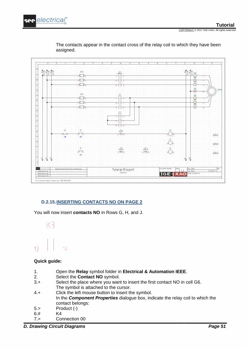
The contacts appear in the contact cross of the relay coil to which they have been assigned.
D.2.15. INSERTING CONTACTS NO ON PAGE 2 You will now insert contacts NO in Rows G, H, and J.
Quick guide: 1. Open the Relay symbol folder in Electrical & Automation IEEE. 2. Select the Contact NO symbol. 3.+ Select the place where you want to insert the first contact NO in cell G6.
The symbol is attached to the cursor. 4.+ Click the left mouse button to insert the symbol.
In the Component Properties dialogue box, indicate the relay coil to which the contact belongs:
5.> Product (-) 6.# K4 7.> Connection 00

Tutorial
COPYRIGHT © 2017 IGE+XAO. All rights reserved
Page 52 D. Drawing Circuit Diagrams
8.# 13
Fill in the first connection number of the contact. 9.> Connection 01 10.# 14
Fill in the second connection number of the contact. 11.> OK 12.+ Select the place where you want to insert the contact NO in cell H2. Click the left
mouse button to insert the symbol. In the Component Properties dialogue box, indicate the relay coil to which the contact belongs:
13.> Product (-) 14.# K3 15.> Connection 00 16.# 13
Fill in the first connection number of the contact. 17.> Connection 01 18.# 14
Fill in the second connection number of the contact. 19.> OK 20.+ Insert the contact again (cell J2) by clicking the left mouse button.
In the Component Properties dialogue box, indicate the relay coil to which the contact belongs:
21.> Product (-) 22.# K5 23.> Connection 00 24.# 13
Fill in the first connection number of the contact. 25.> Connection 01 26.# 14
Fill in the second connection number of the contact. 27.> OK
Right-click to exit the insertion mode. The contacts appear in the contact cross of the corresponding relay coil.
D.2.16. DRAWING WIRES ON PAGE 2 You will now connect the horizontal wire in Row G to the symbols in rows H and I. Quick guide: 1.CA Electrical IEEE 2.CO 1 Wire (Wire Connections panel)

Tutorial
COPYRIGHT © 2017 IGE+XAO. All rights reserved
D. Drawing Circuit Diagrams Page 53
Draw the following wire first:
3.+ Select the starting point of the wire on the horizontal connection between S5 and S3
in column 1. 4.+ Draw the wire, going vertically down to row J on the left of connection 13 of the K5
contact NO. Place the corner point of the wire by clicking the left mouse button. 5.+ Draw the wire horizontally through the K5 contact NO in column 2. Go vertically and
align the wire with the S4 push button. Draw the next connection:
6.+ Select the starting point of the wire on the right of the S3 push button (column 2). Go
vertically to row H and align the end of the wire with the K3 connections. 7.+ Continue the wire through K3 to the existing vertical wire in column 1.

Tutorial
COPYRIGHT © 2017 IGE+XAO. All rights reserved
Page 54 D. Drawing Circuit Diagrams
Draw the next connection:
8.+ Select the starting point of the wire on the potential N (on the right of the relay coil K4 in row H).
9.+ Draw the wire horizontally (through the relay coil K4). Place the corner point of the wire by clicking the left mouse button.
10.+ Draw the wire vertically upwards to the existing horizontal connection. Draw the next connection in row I:
11.+ Select the starting point of the wire on the vertical wire connection on the left of the
S4 push button in row I. 12.+ Draw the wire horizontally towards to the potential N. Place the ending point of the
wire by clicking the left mouse button. Right-click to exit wire drawing mode.
D.2.17. DRAWING A CABLE ON PAGE 2 You will now insert a cable between terminal strip TB3 and motor 2MTR1. Quick guide: 1.CA Electrical IEEE 2.CO Cable (Cable panel)
Cables must run across wires, not across elements of symbols. 3.+ Select the starting point of the cable. 4.+ Select the ending point of the cable.

Tutorial
COPYRIGHT © 2017 IGE+XAO. All rights reserved
D. Drawing Circuit Diagrams Page 55
The Component Properties dialogue of the cable is displayed. It allows you to fill in the information for all cable cores. Fill in the desired information of the cable:
5.> Product (-) 6.# W2 7.> Type 8.# U-1000 R2V 12G1,5²
This is an example of a type. 9.> Cable-core No. 10.# 1
The cores are numbered in succession, from left to right, starting with 1 for each new cable.
11.# Cable-core Colour In case a valid type has been selected, the cable core colors are filled in according to the information from the type database (Standard and Advanced).
12.# Cable-core Size In case a valid type has been selected, the cable core sizes are filled in according to the information from the type database (Standard and Advanced).
13.> OK

Tutorial
COPYRIGHT © 2017 IGE+XAO. All rights reserved
Page 56 D. Drawing Circuit Diagrams
Right-click to exit the cable insertion mode.
Hints
According to IEEE Std 91/91, the letter code for cables must be "W". If you use the advanced level of SEE Electrical and you have set user-defined cables via the Cables setup… button in the Cables tab of the Circuit Diagrams (IEEE) Properties window,
the Electrical IEEE ➤ Cable ➤ Cable command allows you to insert a predefined cable.
Select the desired predefined cable type, or click the Default button.

Tutorial
COPYRIGHT © 2017 IGE+XAO. All rights reserved
D. Drawing Circuit Diagrams Page 57
D.2.18. PAGE 2 ILLUSTRATED
Congratulations! You have now completed the second page in the workspace example. The page is illustrated below:
Saving the workspace You must save the workspace.
1. File ➤ Save

Tutorial
COPYRIGHT © 2017 IGE+XAO. All rights reserved
Page 58 E. Additional Processing of Circuit Diagrams
E ADDITIONAL PROCESSING OF CIRCUIT DIAGRAMS
E.1. PAGE INDEX If an installation has just been built, it is often necessary to add pages in order to have additional circuit parts in the project. If a page numbering for the component names is used, then the names of the components which are already installed must not be changed. The page index allows inserting pages without changing the numbers of the existing ones. You will now insert page 1a in the workspace. 1. Create a new page using the same approach as for the creation of page 2.
2.> Page
Change the page number. 3.# 1 4.> Index 5.# a
Type in the page index. 6.> OK
The page has been created. Place a symbol of a lamp on page 1a. It is automatically named 1aLT1, because in our example the component names are created using the page number. When you draw the potential L1 on page 1a, the cross-references on pages 1 and 2 will be updated. The same happens to the cross references of coils and contacts. They will also be updated using the information of the page index.

Tutorial
COPYRIGHT © 2017 IGE+XAO. All rights reserved
E. Additional Processing of Circuit Diagrams Page 59
Saving the workspace You must save the workspace.
1. File ➤ Save
E.2. TEXTS You can insert comment texts in a page. Insert the texts "Motor 1" and "Motor 2" in page 2.

Tutorial
COPYRIGHT © 2017 IGE+XAO. All rights reserved
Page 60 E. Additional Processing of Circuit Diagrams
1.CA Draw 2.CO New Text (Elements panel) The Text dialogue is displayed.
Hint
In order to call the Text dialogue, in which you can create a new text, click the icon.
3.+ Move the cursor into the input field. 4.# Motor 1
Type in the text.
5.> Tick the "Show advanced properties" checkbox and select the desired text attributes, such as size, highlight colour and adjustment (Left justified, or Center justified).

Tutorial
COPYRIGHT © 2017 IGE+XAO. All rights reserved
E. Additional Processing of Circuit Diagrams Page 61
6.+ Insert the text in the drawing by clicking at the desired position.
The Text dialogue box remains open. 7.+ Move the cursor into the input field again. 8. Change the existing text or type in a new text, place the text in the drawing, etc.
9.> Click the button to close the Text dialogue box. Now you will change the text you have just inserted. 1.CA Edit 2.CO Edit Text (Text panel) 3.+ Click the text you want to change. The Text dialogue is displayed and you can see the text in the input field.
Hint
In order to call the Text dialogue, in which you can change/edit a text, you have to:
▪ Click the icon. When you move the cursor to the drawing, its graphic changes.
▪ Click the text to change. The Text dialogue, which contains the respective text, is displayed.
4.# Type "90.00" degrees in the "Angle" field. 5.# <Text>
Change the text "Motor 1" to "Motor FU3P1". The change can be seen directly in the drawing.

Tutorial
COPYRIGHT © 2017 IGE+XAO. All rights reserved
Page 62 E. Additional Processing of Circuit Diagrams
6.> If you want, tick the "Show advanced properties" checkbox and change the desired
text attributes, such as size, highlight colour and adjustment (Left justified, or Center justified).
7.+ Click the next text you want to change: "Motor 2" to "Motor FU3P2", for example. The Text dialogue box remains open.
8.+ Move the cursor into the input field again. 9. Change the existing text, etc.
10.> Click the button to close the Text dialogue box.

Tutorial
COPYRIGHT © 2017 IGE+XAO. All rights reserved
F. Printing Page 63
F PRINTING
F.1. PRINT After the project is completed, it can be printed. 1.CA File 2.CO Print 3.CO Print… The Diagram Printing window is displayed.

Tutorial
COPYRIGHT © 2017 IGE+XAO. All rights reserved
Page 64 F. Printing
The "Use page properties for printing" option allows you to print the pages in their current orientation - landscape (since the default orientation used by most printers is "portrait"). When enabled, the pages are printed in the orientation defined in the page template.
F.2. PRINT PREVIEW A print preview is available for single pages of the project. This function can be accessed by
clicking the Print preview button in the Diagram Printing window or by executing the File ➤
Print ➤ Print Preview command.
You will now display a print preview of the active page. 1.CA File 2.CA Print 3.CA Print Preview
A print preview of the currently active page appears.
4.> Click the icon to zoom the preview. 5.> Click the Close button to exit the print preview.

Tutorial
COPYRIGHT © 2017 IGE+XAO. All rights reserved
G. Closing Remarks Page 65
G CLOSING REMARKS We hope you have found this tutorial useful and informative. You should now have a general understanding of the steps involved in producing electrical schematics with SEE Electrical Free. The functions outlined here are only the tip of the iceberg in terms of what can be achieved using the packages sold by IGE+XAO. Other functionalities include: Creation of custom symbols with their associated electrical properties. Creation of customized page and workspace templates. Project development based on a Function/Location hierarchy, allowing multiple users to
work on different parts of the same project, and then merge these together. Sophisticated handling of PLCs. Creation of dimensioned control cabinets with components linked to the main electrical
schematic. Creation of building installation plans, with electrical components and cables linked back to
the electrical schematic. Language translation of complete projects at the press of a button. Creation of customized graphical and database lists. Auto-diagramming function, allowing instant creation of circuit schematics directly from an
Excel spreadsheet. And a lot more.
If you need help with any of the above, please contact our helpdesk.