getting started - panasonic · 1.2 network devices and numbering plan getting started 9 1.2.2...
TRANSCRIPT

KX-TDA3480 Model KX-TDA0484
4-Channel VoIP Gateway Card
Getting Started
Thank you for purchasing a Panasonic 4-Channel VoIP Gateway Card.Please read this manual carefully before using this product and save this manual for future use.

Table of Contents
1 Overview.................................................................................................. 51.1 Example Network Diagram...............................................................................................61.2 Network Devices and Numbering Plan ...........................................................................71.2.1 Network Application ............................................................................................................81.2.2 Numbering Plan Example ...................................................................................................91.2.3 Numbering Plan Summary................................................................................................12
2 Installing in the KX-TDA30 PBX .......................................................... 132.1 Installation .......................................................................................................................142.1.1 Names and Locations .......................................................................................................142.1.2 Installing the VoIP Gateway Card in the PBX....................................................................152.2 Cable Connection............................................................................................................172.2.1 Connection for Programming ............................................................................................172.2.2 Connection to the LAN......................................................................................................18
3 Installing in the KX-TDA100/KX-TDA200/KX-TDA600 PBX................ 193.1 Installation .......................................................................................................................203.1.1 Names and Locations .......................................................................................................203.1.2 Installing the VoIP Gateway Card in the PBX....................................................................213.2 Cable Connection............................................................................................................233.2.1 Connection for Programming ............................................................................................233.2.2 Connection to the LAN......................................................................................................24
4 Programming the VoIP Gateway Card ................................................ 254.1 Preparations ....................................................................................................................264.1.1 Preparing the PC ..............................................................................................................264.2 Programming the VoIP Gateway Card in the Los Angeles Office...............................294.2.1 Starting the IP-GW4 Maintenance Utility ..........................................................................294.2.2 Changing the Status of the VoIP Gateway Card ...............................................................314.2.3 Assigning the IP Address..................................................................................................324.2.4 Assigning the Hunt Pattern ...............................................................................................334.2.5 Programming the Address Translation Table.....................................................................344.2.6 Downloading the Address Translation Table from the VoIP Gateway Card.......................374.2.7 Rebooting the VoIP Gateway Card ...................................................................................384.2.8 Confirming the IP Address Assignment ............................................................................394.3 Programming the VoIP Gateway Card in the Chicago Office ......................................40
5 Programming the PBX.......................................................................... 455.1 Programming the PBX in the Los Angeles Office........................................................465.2 Programming the PBX in the Chicago Office ...............................................................49
A Guidance for VoIP Installation............................................................. 53A1 VoIP Requirements .........................................................................................................54A1.1 Bandwidth Assessment.....................................................................................................54A1.2 Network Configuration.......................................................................................................56A1.3 Network Devices ...............................................................................................................59A1.4 QoS (Quality of Service) ...................................................................................................60A2 VoIP Requirements Checklist.........................................................................................61
2 Getting Started

B Alternative Numbering Plan Example .................................................63B1 Extension Number Method............................................................................................ 64B1.1 Example Network ............................................................................................................. 64B1.2 Numbering Plan Example................................................................................................. 65B2 Programming for the Extension Number Method ....................................................... 67B2.1 Programming the VoIP Gateway Card.............................................................................. 67B2.2 Programming the PBX...................................................................................................... 68
C Initialisation of the VoIP Gateway Card...............................................73C1 Initialising the VoIP Gateway Card................................................................................ 74
D Using the KX-TDA3480/KX-TDA0484 and KX-TDA0480 in One Network..................................................................................................77
D1 Considerations in Installation ....................................................................................... 78
Getting Started 3

4 Getting Started
Section 1
Overview
Panasonic PBX with VoIP Gateway Card will allow organisations to route both voice and fax communications over digital data networks.
The VoIP Gateway Card, designed to be easily integrated into existing IP networks, seamlessly bridges Public Switched Telephone Network (PSTN) and analogue telephones with digital data networks without interrupting pre-existing data communications. Because communications do not take place over conventional telephone networks, the high cost of long distance communications is virtually eliminated.
Getting Started 5
1.1 Example Network Diagram
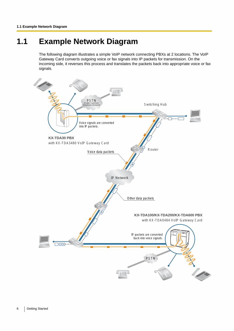
1.1 Example Network DiagramThe following diagram illustrates a simple VoIP network connecting PBXs at 2 locations. The VoIP Gateway Card converts outgoing voice or fax signals into IP packets for transmission. On the incoming side, it reverses this process and translates the packets back into appropriate voice or fax signals.
PSTN(Public Switched
Telephone Network)
IP Network
PSTN
Voice signals are converted into IP packets.
Router
Switching Hub
KX-TDA30 PBXwith KX-TDA3480 VoIP Gateway Card
Other data packets
Voice data packets
IP packets are converted back into voice signals.
KX-TDA100/KX-TDA200/KX-TDA600 PBXwith KX-TDA0484 VoIP Gateway Card
6 Getting Started
1.2 Network Devices and Numbering Plan
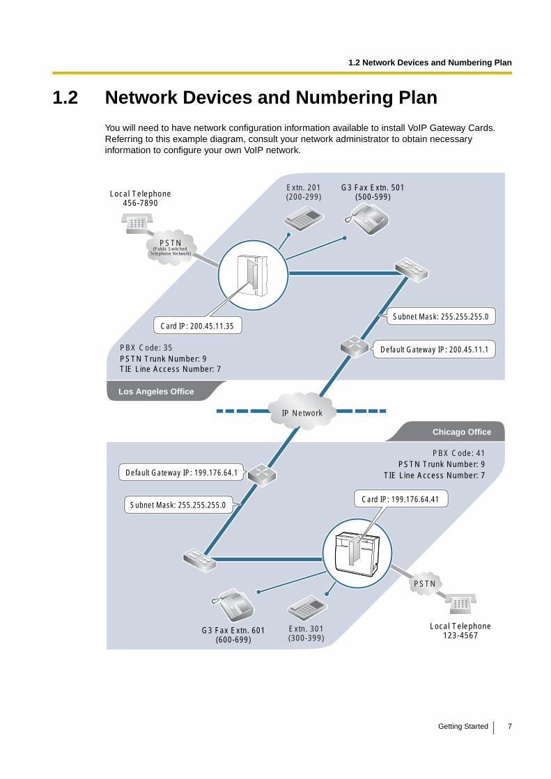
1.2 Network Devices and Numbering PlanYou will need to have network configuration information available to install VoIP Gateway Cards. Referring to this example diagram, consult your network administrator to obtain necessary information to configure your own VoIP network.
PSTN(Public Switched
Telephone Network)
IP Network
Chicago Office
PBX Code: 41PSTN Trunk Number: 9
TIE Line Access Number: 7
PSTN
Local Telephone123-4567
Extn. 301(300-399)
PBX Code: 35PSTN Trunk Number: 9TIE Line Access Number: 7
Extn. 201(200-299)Local Telephone
456-7890
G3 Fax Extn. 501(500-599)
G3 Fax Extn. 601(600-699)
Default Gateway IP: 200.45.11.1
Subnet Mask: 255.255.255.0Card IP: 200.45.11.35
Subnet Mask: 255.255.255.0
Los Angeles Office
Default Gateway IP: 199.176.64.1
Card IP: 199.176.64.41
Getting Started 7
1.2 Network Devices and Numbering Plan
1.2.1 Network Application
QSIG Network InterfaceQSIG is a protocol based on ISDN (Q.931) that offers enhanced PBX features in a private network. The QSIG network supports private communications by the TIE line service method. Implementation of VoIP Gateway Cards provides a VoIP interface to employ a QSIG network between PBXs at different locations by using an IP network instead of conventional telephone networks.
Types of IP NetworkThe VoIP Gateway Card's quality of performance depends on the type of IP network in use. Managed IP networks provide better quality of service compared to unmanaged networks, where quality of service is not guaranteed.
Examples of recommended IP networks
• Digital Leased Line
• IP-VPN (Virtual Private Network)
• Frame Relay
Notice
The performance of the VoIP Gateway Card may deteriorate when it is used on the Internet. Delays and loss in data transmission can degrade speech quality, and impair the card's capability to use the enhanced networking features of the PBX (for more information about these features, refer to the relevant sections of the Hybrid IP-PBX documentation.)
Using the KX-TDA3480/KX-TDA0484 with Other KX-TDA Series VoIP Gateway Cards
When using the KX-TDA3480/KX-TDA0484 in a network that contains other KX-TDA series VoIP Gateway Cards, keep in mind the following points:
1. Making and Receiving Calls
Calls can be made and received between the KX-TDA3480/KX-TDA0484 and other KX-TDA series VoIP Gateway Cards. However, the KX-TDA0480 requires a special setting to be able to communicate with the KX-TDA3480/KX-TDA0484 on the network. Refer to "D1 Considerations in Installation" for more details.
2. Using QSIG Services
All QSIG services available with the PBX can be used between the KX-TDA3480/KX-TDA0484 and KX-TDA0490. However, CLIP service is the only available QSIG service between the KX-TDA3480/KX-TDA0484 and KX-TDA0480.
FirewallA firewall protects the internal networks of an organisation against unauthorised penetration from outside. When routing a VoIP network through a firewall, some performance degradation may result. If for practical reasons you must route the VoIP network through a firewall, refer to "A1.3 Network Devices" for more details.
8 Getting Started
1.2 Network Devices and Numbering Plan
1.2.2 Numbering Plan Example
There are 2 methods to plan your numbering system, as follows:
This section provides a network numbering mechanism using the PBX code method based on the previous example diagram. Configure your network referring to this example.
Note
An example using the extension number method is provided in "B Alternative Numbering Plan Example".
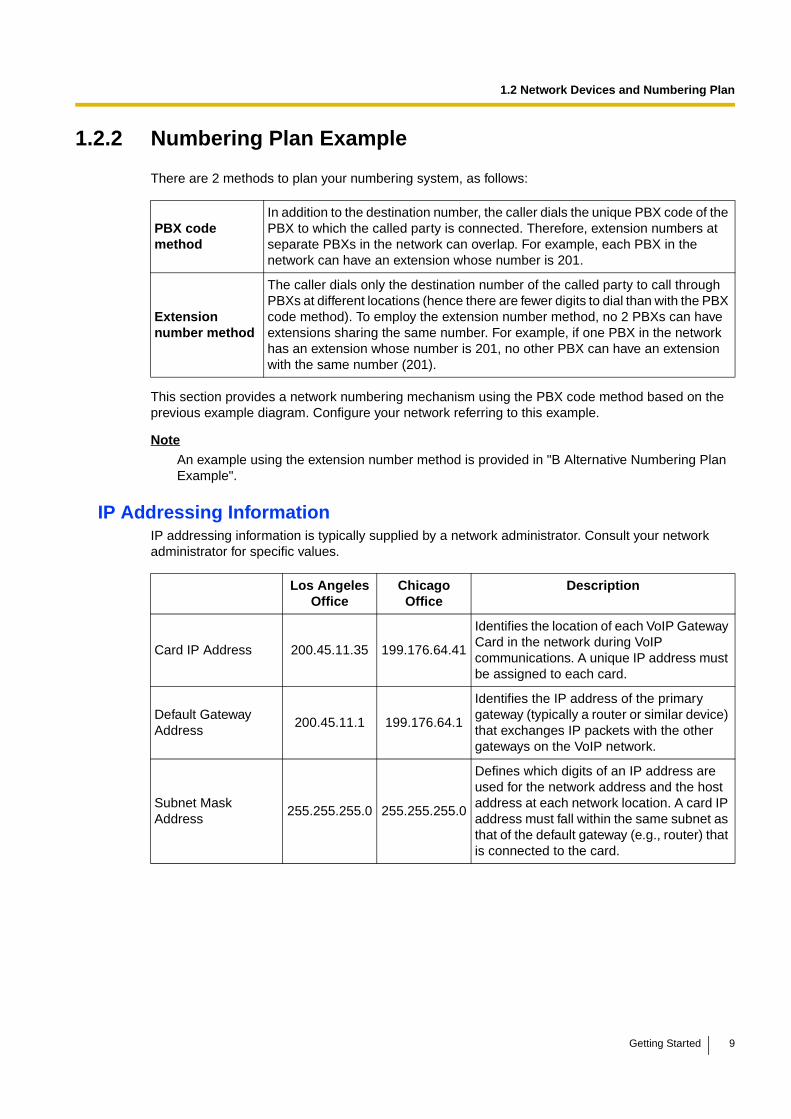
IP Addressing InformationIP addressing information is typically supplied by a network administrator. Consult your network administrator for specific values.
PBX code method
In addition to the destination number, the caller dials the unique PBX code of the PBX to which the called party is connected. Therefore, extension numbers at separate PBXs in the network can overlap. For example, each PBX in the network can have an extension whose number is 201.
Extension number method
The caller dials only the destination number of the called party to call through PBXs at different locations (hence there are fewer digits to dial than with the PBX code method). To employ the extension number method, no 2 PBXs can have extensions sharing the same number. For example, if one PBX in the network has an extension whose number is 201, no other PBX can have an extension with the same number (201).
Los Angeles Office
Chicago Office
Description
Card IP Address 200.45.11.35 199.176.64.41
Identifies the location of each VoIP Gateway Card in the network during VoIP communications. A unique IP address must be assigned to each card.
Default Gateway Address
200.45.11.1 199.176.64.1
Identifies the IP address of the primary gateway (typically a router or similar device) that exchanges IP packets with the other gateways on the VoIP network.
Subnet Mask Address
255.255.255.0 255.255.255.0
Defines which digits of an IP address are used for the network address and the host address at each network location. A card IP address must fall within the same subnet as that of the default gateway (e.g., router) that is connected to the card.
Getting Started 9
1.2 Network Devices and Numbering Plan
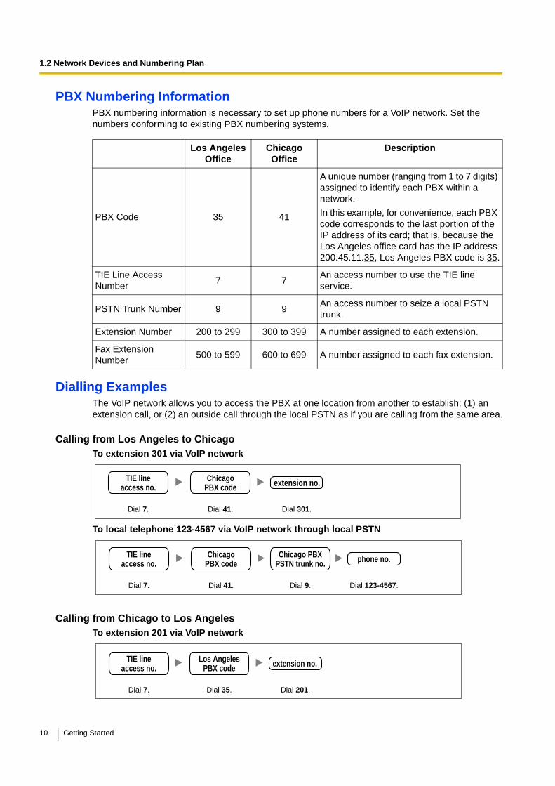
PBX Numbering InformationPBX numbering information is necessary to set up phone numbers for a VoIP network. Set the numbers conforming to existing PBX numbering systems.
Dialling ExamplesThe VoIP network allows you to access the PBX at one location from another to establish: (1) an extension call, or (2) an outside call through the local PSTN as if you are calling from the same area.
Calling from Los Angeles to ChicagoTo extension 301 via VoIP network
To local telephone 123-4567 via VoIP network through local PSTN
Calling from Chicago to Los AngelesTo extension 201 via VoIP network
Los Angeles Office
Chicago Office
Description
PBX Code 35 41
A unique number (ranging from 1 to 7 digits) assigned to identify each PBX within a network.
In this example, for convenience, each PBX code corresponds to the last portion of the IP address of its card; that is, because the Los Angeles office card has the IP address 200.45.11.35, Los Angeles PBX code is 35.
TIE Line Access Number
7 7An access number to use the TIE line service.
PSTN Trunk Number 9 9An access number to seize a local PSTN trunk.
Extension Number 200 to 299 300 to 399 A number assigned to each extension.
Fax Extension Number
500 to 599 600 to 699 A number assigned to each fax extension.
Dial 41.Dial 7. Dial 301.
ChicagoPBX code
TIE lineaccess no. extension no.
Dial 41. Dial 9.Dial 7. Dial 123-4567.
ChicagoPBX code
TIE lineaccess no. phone no.Chicago PBX
PSTN trunk no.
Dial 35.Dial 7. Dial 201.
Los AngelesPBX code
TIE lineaccess no. extension no.
10 Getting Started

1.2 Network Devices and Numbering Plan
To local telephone 456-7890 via VoIP network through local PSTN
PBX Connection InformationPBX connection information is created by combining IP Addressing Information and PBX Numbering Information. Referring to the sample below, create your own PBX connection information.
Leading Number:
A number composed of the PBX code followed by the first digit of the destination number. See the example on the right.
Remaining Digits:
The maximum number of digits to be dialled following the leading number to access the destination. (However, for example, setting the remaining digits to 7 does not mean that the user must dial all 7 digits when making a call.) See the example on the right.
Card IP Address:
The IP address of each card in the network (as the access destination).
Los Angeles Office (PBX Code: 35) Chicago Office (PBX Code: 41)
Extn. FAX Extn. PSTN Access
Extn. FAX Extn. PSTN Access
Leading Number 352 355 359 413 416 419
Remaining Digits 2 2 7 2 2 7
Card IP Address 200.45.11.35 199.176.64.41
Dial 35. Dial 9.Dial 7. Dial 456-7890.
Los AngelesPBX code
TIE lineaccess no. phone no.Los Angeles PBX
PSTN trunk no.
352+00 to 99
PBX Code
Remaining DigitsLeading No.
Los Angeles extensions
First digit of the extension number
Remaining digits of the extension number
Getting Started 11

1.2 Network Devices and Numbering Plan
1.2.3 Numbering Plan Summary
Print this page and write down your network information in the space provided below for each card in the network. Consult your network administrator to fill in the shaded entries.
PSTN(Public Switched
Telephone Network)
IP Network
PBX Code: PSTN Trunk Number: TIE Line Access Number:
Extension Number:Local Telephone: G3 Fax Extension Number:
Subnet Mask:
IP Address
Card IP Address
Default Gateway IP Address
Subnet Mask Address
PBX Numbering
PBX Code
TIE Line Access Number
PSTN Trunk Number
Extension Number
Fax Extension Number
Card IP Address
Extensions
Leading Number
Remaining Digits
PBX Connection
PSTN AccessFax Extensions
Default Gateway IP:
Card IP:
12 Getting Started
Section 2
Installing in the KX-TDA30 PBX
This section describes the physical installation process of the KX-TDA3480 VoIP Gateway Card covering the following topics: (1) installing the card in the KX-TDA30 PBX, and (2) connecting the card to a network device using a Category 5 (CAT5) Ethernet cable.
Getting Started 13
2.1 Installation
2.1 Installation
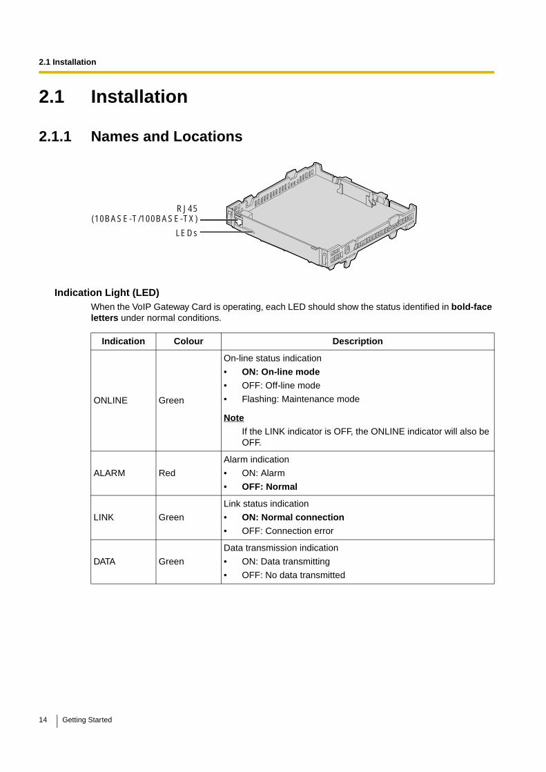
2.1.1 Names and Locations
Indication Light (LED)When the VoIP Gateway Card is operating, each LED should show the status identified in bold-face letters under normal conditions.
Indication Colour Description
ONLINE Green
On-line status indication
• ON: On-line mode
• OFF: Off-line mode
• Flashing: Maintenance mode
Note
If the LINK indicator is OFF, the ONLINE indicator will also be OFF.
ALARM Red
Alarm indication
• ON: Alarm
• OFF: Normal
LINK Green
Link status indication
• ON: Normal connection
• OFF: Connection error
DATA Green
Data transmission indication
• ON: Data transmitting
• OFF: No data transmitted
RJ45(10BASE-T/100BASE-TX)
LEDs
14 Getting Started

2.1 Installation
2.1.2 Installing the VoIP Gateway Card in the PBX
Install the VoIP Gateway Card in slot 05, 06, or 07 of the KX-TDA30 PBX.
1. Before installing the card, cut and remove the dummy cover plate for the appropriate slot from the main unit.
CAUTIONFor safety reasons, smooth the cut edges after removing the dummy cover plate.
2. Position the card in the open slot, making sure that the tabs on both sides of the card fit into place. Then, holding the card firmly in place, lower the rear end so that the hole of the card fits over the extension bolt.
Dummy Cover Plate
1
2
Extension Bolt
Getting Started 15
2.1 Installation
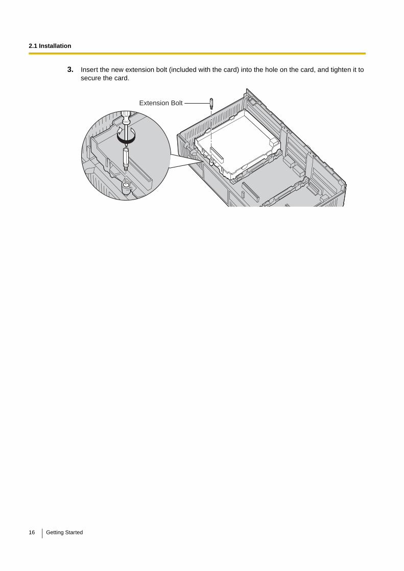
3. Insert the new extension bolt (included with the card) into the hole on the card, and tighten it to secure the card.
Extension Bolt
16 Getting Started

2.2 Cable Connection
2.2 Cable ConnectionUse a Category 5 (CAT5) Ethernet cable (10BASE-T/100BASE-TX) with an RJ45 connector to connect the VoIP Gateway Card to a network device.
When connecting the card to a switching hub, use an Ethernet straight cable; when connecting directly to a router or PC, use an Ethernet cross cable.
Note
Use only CAT5 Ethernet cable for connection.
2.2.1 Connection for Programming
When assigning a new IP address to the VoIP Gateway Card for the first time, connect a PC directly to the card using an Ethernet cross cable.
1. Connect the Ethernet cable to the RJ45 connector of the card.
2. Connect the other end of the cable to the PC.
Ethernet Cross Cable PC
RJ45
Getting Started 17
2.2 Cable Connection
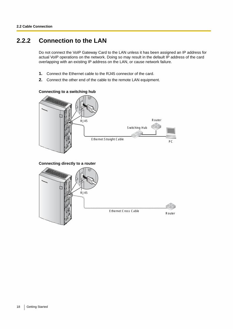
2.2.2 Connection to the LAN
Do not connect the VoIP Gateway Card to the LAN unless it has been assigned an IP address for actual VoIP operations on the network. Doing so may result in the default IP address of the card overlapping with an existing IP address on the LAN, or cause network failure.
1. Connect the Ethernet cable to the RJ45 connector of the card.
2. Connect the other end of the cable to the remote LAN equipment.
Connecting to a switching hub
Connecting directly to a router
Ethernet Straight Cable
Router
Switching Hub
PC
RJ45
Ethernet Cross Cable Router
RJ45
18 Getting Started
Section 3
Installing in the KX-TDA100/KX-TDA200/KX-TDA600 PBX
This section describes the physical installation process of the KX-TDA0484 VoIP Gateway Card covering the following topics: (1) installing the card in the KX-TDA100/KX-TDA200/KX-TDA600 PBX, and (2) connecting the card to a network device using a Category 5 (CAT5) Ethernet cable.
Getting Started 19
3.1 Installation
3.1 Installation
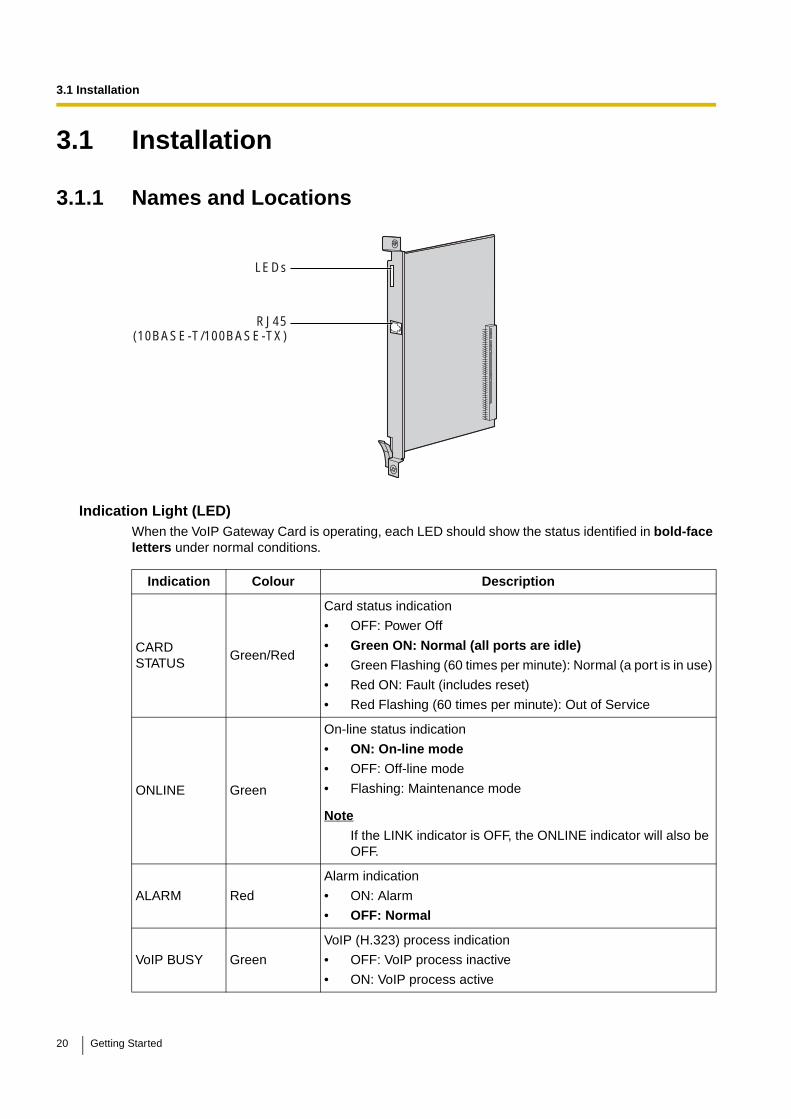
3.1.1 Names and Locations
Indication Light (LED)When the VoIP Gateway Card is operating, each LED should show the status identified in bold-face letters under normal conditions.
Indication Colour Description
CARD STATUS
Green/Red
Card status indication
• OFF: Power Off
• Green ON: Normal (all ports are idle)
• Green Flashing (60 times per minute): Normal (a port is in use)
• Red ON: Fault (includes reset)
• Red Flashing (60 times per minute): Out of Service
ONLINE Green
On-line status indication
• ON: On-line mode
• OFF: Off-line mode
• Flashing: Maintenance mode
Note
If the LINK indicator is OFF, the ONLINE indicator will also be OFF.
ALARM Red
Alarm indication
• ON: Alarm
• OFF: Normal
VoIP BUSY Green
VoIP (H.323) process indication
• OFF: VoIP process inactive
• ON: VoIP process active
LEDs
RJ45(10BASE-T/100BASE-TX)
20 Getting Started
3.1 Installation
3.1.2 Installing the VoIP Gateway Card in the PBX
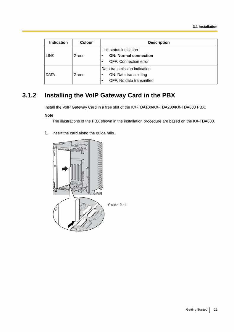
Install the VoIP Gateway Card in a free slot of the KX-TDA100/KX-TDA200/KX-TDA600 PBX.
Note
The illustrations of the PBX shown in the installation procedure are based on the KX-TDA600.
1. Insert the card along the guide rails.
LINK Green
Link status indication
• ON: Normal connection
• OFF: Connection error
DATA Green
Data transmission indication
• ON: Data transmitting
• OFF: No data transmitted
Indication Colour Description
Guide Rail
Getting Started 21
3.1 Installation
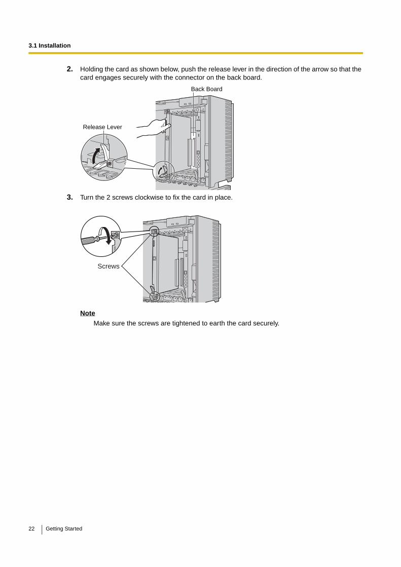
2. Holding the card as shown below, push the release lever in the direction of the arrow so that the card engages securely with the connector on the back board.
3. Turn the 2 screws clockwise to fix the card in place.
Note
Make sure the screws are tightened to earth the card securely.
Release Lever
Back Board
Screws
22 Getting Started

3.2 Cable Connection
3.2 Cable ConnectionUse a Category 5 (CAT5) Ethernet cable (10BASE-T/100BASE-TX) with an RJ45 connector to connect the VoIP Gateway Card to a network device.
When connecting the card to a switching hub, use an Ethernet straight cable; when connecting directly to a router or PC, use an Ethernet cross cable.
Note
Use only CAT5 Ethernet cable for connection.
3.2.1 Connection for Programming
When assigning a new IP address to the VoIP Gateway Card for the first time, connect a PC directly to the card using an Ethernet cross cable.
1. Connect the Ethernet cable to the RJ45 connector of the card.
2. Connect the other end of the cable to the PC.
Ethernet Cross Cable PC
RJ45
Getting Started 23

3.2 Cable Connection
3.2.2 Connection to the LAN
Do not connect the VoIP Gateway Card to the LAN unless it has been assigned an IP address for actual VoIP operations on the network. Doing so may result in the default IP address of the card overlapping with an existing IP address on the LAN, or cause network failure.
1. Connect the Ethernet cable to the RJ45 connector of the card.
2. Connect the other end of the cable to the remote LAN equipment.
Connecting to a switching hub
Connecting directly to a router
Ethernet Straight Cable
Router
Switching Hub
PC
RJ45
Ethernet Cross Cable Router
RJ45
24 Getting Started
Section 4
Programming the VoIP Gateway Card
One way of setting up a VoIP network for the first time is to go through the whole programming process of a VoIP Gateway Card at one location in the network, then start programming the other cards at different locations.
Based on the theoretical network illustrated previously in this manual, this section demonstrates the procedure to programme the cards in the Los Angeles and Chicago offices.
Getting Started 25

4.1 Preparations
4.1 PreparationsA web programming utility called the IP-GW4 Maintenance Utility is available for programming of the VoIP Gateway Card.
For a complete discussion of web programming, refer to the VoIP Gateway Card Programming Guide.
System Requirements
• The IP-GW4 Maintenance Utility requires Microsoft® Internet Explorer 5.0 or above.
Trademarks
• Microsoft is either a registered trademark or trademark of Microsoft Corporation in the United States and/or other countries.
• All other trademarks identified herein are the property of their respective owners.
• Screen shots reprinted with permission from Microsoft Corporation.
4.1.1 Preparing the PC
To prepare for programming using the IP-GW4 Maintenance Utility, configure your PC by (1) assigning an IP address that belongs to the same network as that of the VoIP Gateway Card, and (2) choosing the appropriate options for the Internet properties.
Note
The procedure below is based on the Windows XP operating system as an example.
1. Open Internet Protocol (TCP/IP) Properties from the Start menu.
2. a. Click Use the following IP address.
b. In the IP address box, type 192.168.1.100.
This is an example entry for the case when the card has the default IP address (192.168.1.200).
c. In the Subnet mask box, type 255.255.255.0.
d. Click OK.
3. a. Start Internet Explorer from the Start menu.
b. Click Internet Options from the Tools menu.
26 Getting Started
4.1 Preparations
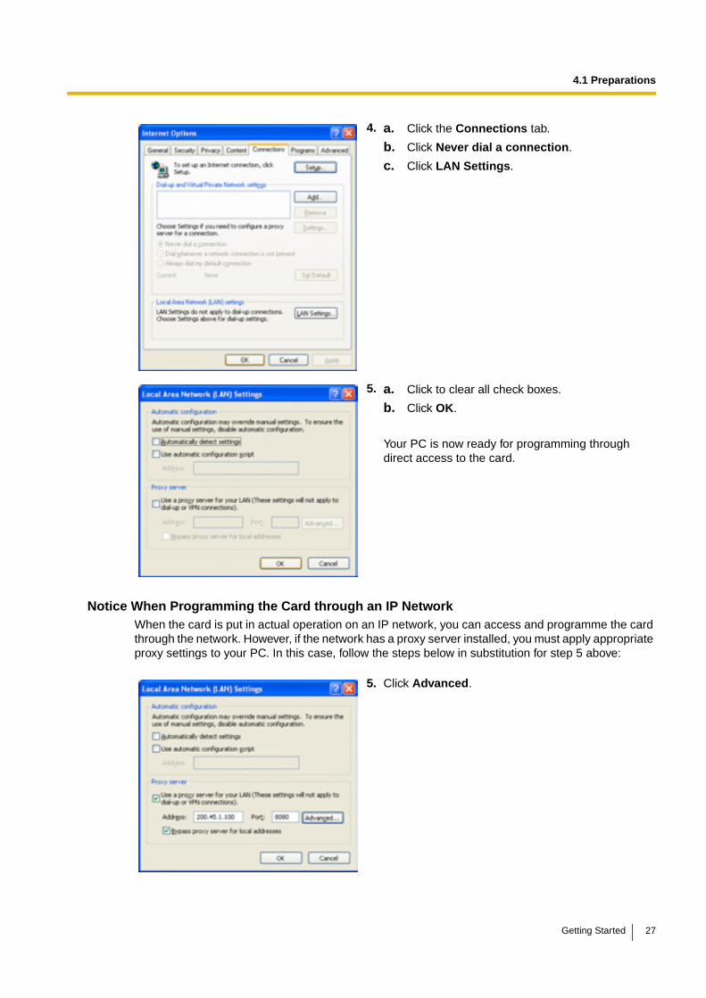
Notice When Programming the Card through an IP NetworkWhen the card is put in actual operation on an IP network, you can access and programme the card through the network. However, if the network has a proxy server installed, you must apply appropriate proxy settings to your PC. In this case, follow the steps below in substitution for step 5 above:
4. a. Click the Connections tab.
b. Click Never dial a connection.
c. Click LAN Settings.
5. a. Click to clear all check boxes.
b. Click OK.
Your PC is now ready for programming through direct access to the card.
5. Click Advanced.
Getting Started 27
4.1 Preparations
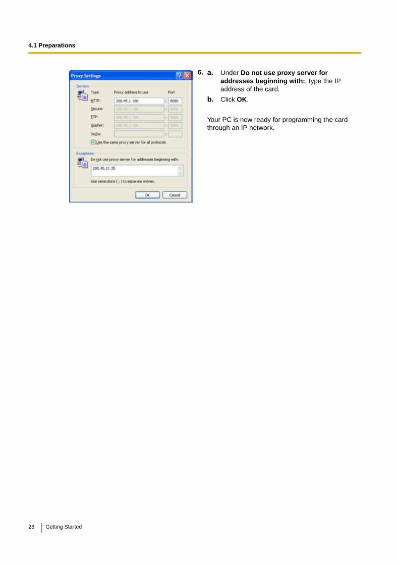
6. a. Under Do not use proxy server for addresses beginning with:, type the IP address of the card.
b. Click OK.
Your PC is now ready for programming the card through an IP network.
28 Getting Started
4.2 Programming the VoIP Gateway Card in the Los Angeles Office
4.2 Programming the VoIP Gateway Card in the Los Angeles OfficeBased on the example network in "1.2 Network Devices and Numbering Plan", this section demonstrates the procedure to programme a VoIP Gateway Card for use in the Los Angeles office, as the first step of setting up a VoIP network. VoIP communications between the 2 offices will be possible when the cards, as well as the PBXs, in both offices are fully programmed.
The procedure to programme the card in the Chicago office is given in "4.3 Programming the VoIP Gateway Card in the Chicago Office". In addition, the procedure to programme the PBXs is given in "5 Programming the PBX".
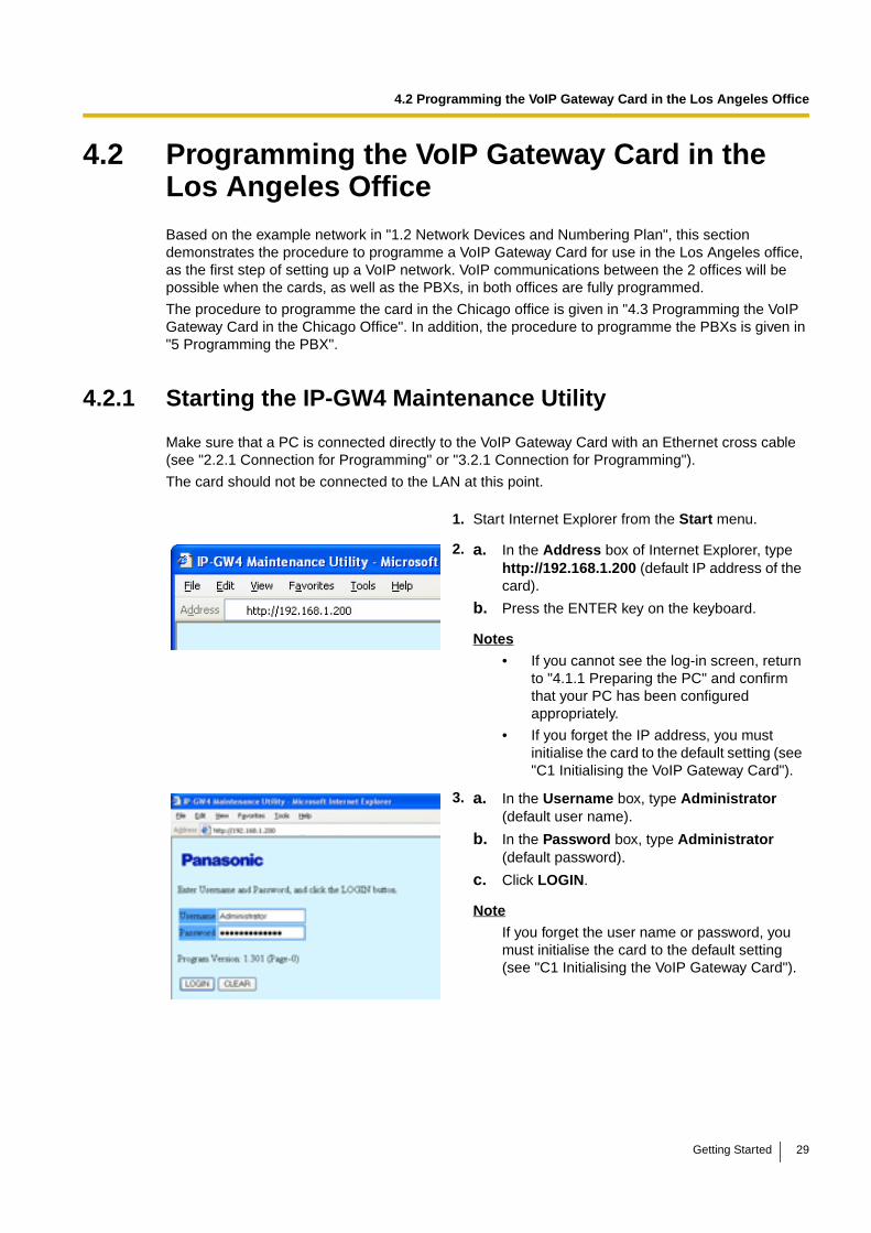
4.2.1 Starting the IP-GW4 Maintenance Utility
Make sure that a PC is connected directly to the VoIP Gateway Card with an Ethernet cross cable (see "2.2.1 Connection for Programming" or "3.2.1 Connection for Programming").
The card should not be connected to the LAN at this point.
1. Start Internet Explorer from the Start menu.
2. a. In the Address box of Internet Explorer, type http://192.168.1.200 (default IP address of the card).
b. Press the ENTER key on the keyboard.
Notes
• If you cannot see the log-in screen, return to "4.1.1 Preparing the PC" and confirm that your PC has been configured appropriately.
• If you forget the IP address, you must initialise the card to the default setting (see "C1 Initialising the VoIP Gateway Card").
3. a. In the Username box, type Administrator (default user name).
b. In the Password box, type Administrator (default password).
c. Click LOGIN.
Note
If you forget the user name or password, you must initialise the card to the default setting (see "C1 Initialising the VoIP Gateway Card").
Getting Started 29
4.2 Programming the VoIP Gateway Card in the Los Angeles Office
Note
If you finish a programming session without logging out from the card (e.g., quitting Internet Explorer, or returning to the log-in screen with the "Back" button of Internet Explorer), you cannot log in again for the period of time specified by the parameter Programming Auto Disconnect Time (default: 10 min).
For the log-out procedure and Programming Auto Disconnect Time setting, refer to "2.5.2 Log Out" and "2.3.2 Maintenance Settings" of the VoIP Gateway Card Programming Guide, respectively.
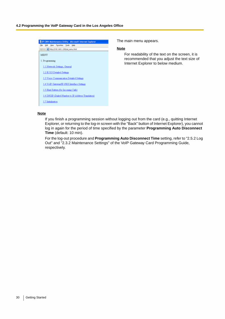
The main menu appears.
Note
For readability of the text on the screen, it is recommended that you adjust the text size of Internet Explorer to below medium.
30 Getting Started
4.2 Programming the VoIP Gateway Card in the Los Angeles Office
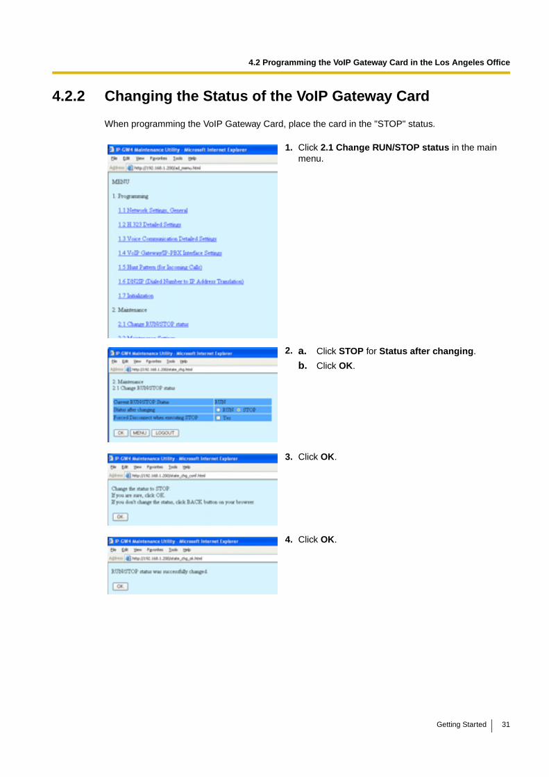
4.2.2 Changing the Status of the VoIP Gateway Card
When programming the VoIP Gateway Card, place the card in the "STOP" status.
1. Click 2.1 Change RUN/STOP status in the main menu.
2. a. Click STOP for Status after changing.
b. Click OK.
3. Click OK.
4. Click OK.
Getting Started 31
4.2 Programming the VoIP Gateway Card in the Los Angeles Office
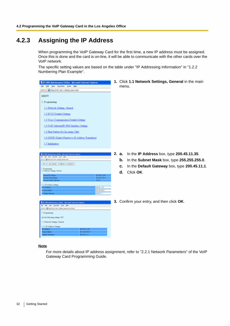
4.2.3 Assigning the IP Address
When programming the VoIP Gateway Card for the first time, a new IP address must be assigned. Once this is done and the card is on-line, it will be able to communicate with the other cards over the VoIP network.
The specific setting values are based on the table under "IP Addressing Information" in "1.2.2 Numbering Plan Example".
NoteFor more details about IP address assignment, refer to "2.2.1 Network Parameters" of the VoIP Gateway Card Programming Guide.
1. Click 1.1 Network Settings, General in the main menu.
2. a. In the IP Address box, type 200.45.11.35.
b. In the Subnet Mask box, type 255.255.255.0.
c. In the Default Gateway box, type 200.45.11.1.
d. Click OK.
3. Confirm your entry, and then click OK.
32 Getting Started

4.2 Programming the VoIP Gateway Card in the Los Angeles Office
4.2.4 Assigning the Hunt Pattern
The hunt pattern determines how to route incoming calls through the VoIP Gateway Card to the PBX.
Note
For more details about hunt pattern assignment, refer to "2.2.5 Hunt Pattern Parameters" of the VoIP Gateway Card Programming Guide.
1. Click 1.5 Hunt Pattern (for Incoming Calls) in the main menu.
2. a. In the Hunt Pattern No. box, type 1.
A hunt pattern will be created with this numbering.
b. In the Receive Leading Number box, type 35 (PBX code).
c. Click ENTRY.
d. Click OK.
3. Confirm your entry, and then click OK.
Getting Started 33
4.2 Programming the VoIP Gateway Card in the Los Angeles Office
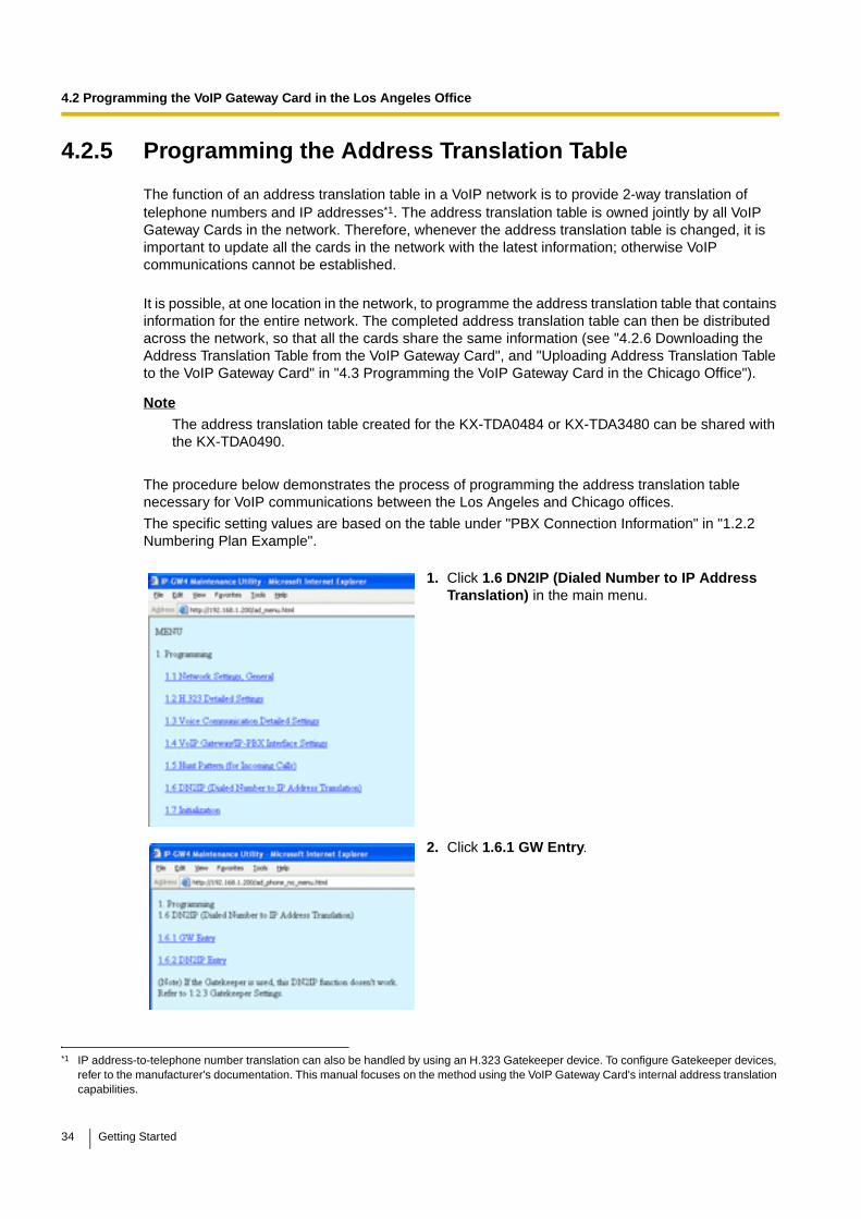
4.2.5 Programming the Address Translation Table
The function of an address translation table in a VoIP network is to provide 2-way translation of telephone numbers and IP addresses*1. The address translation table is owned jointly by all VoIP Gateway Cards in the network. Therefore, whenever the address translation table is changed, it is important to update all the cards in the network with the latest information; otherwise VoIP communications cannot be established.
It is possible, at one location in the network, to programme the address translation table that contains information for the entire network. The completed address translation table can then be distributed across the network, so that all the cards share the same information (see "4.2.6 Downloading the Address Translation Table from the VoIP Gateway Card", and "Uploading Address Translation Table to the VoIP Gateway Card" in "4.3 Programming the VoIP Gateway Card in the Chicago Office").
NoteThe address translation table created for the KX-TDA0484 or KX-TDA3480 can be shared with the KX-TDA0490.
The procedure below demonstrates the process of programming the address translation table necessary for VoIP communications between the Los Angeles and Chicago offices.
The specific setting values are based on the table under "PBX Connection Information" in "1.2.2 Numbering Plan Example".
*1 IP address-to-telephone number translation can also be handled by using an H.323 Gatekeeper device. To configure Gatekeeper devices, refer to the manufacturer's documentation. This manual focuses on the method using the VoIP Gateway Card's internal address translation capabilities.
1. Click 1.6 DN2IP (Dialed Number to IP Address Translation) in the main menu.
2. Click 1.6.1 GW Entry.
34 Getting Started
4.2 Programming the VoIP Gateway Card in the Los Angeles Office
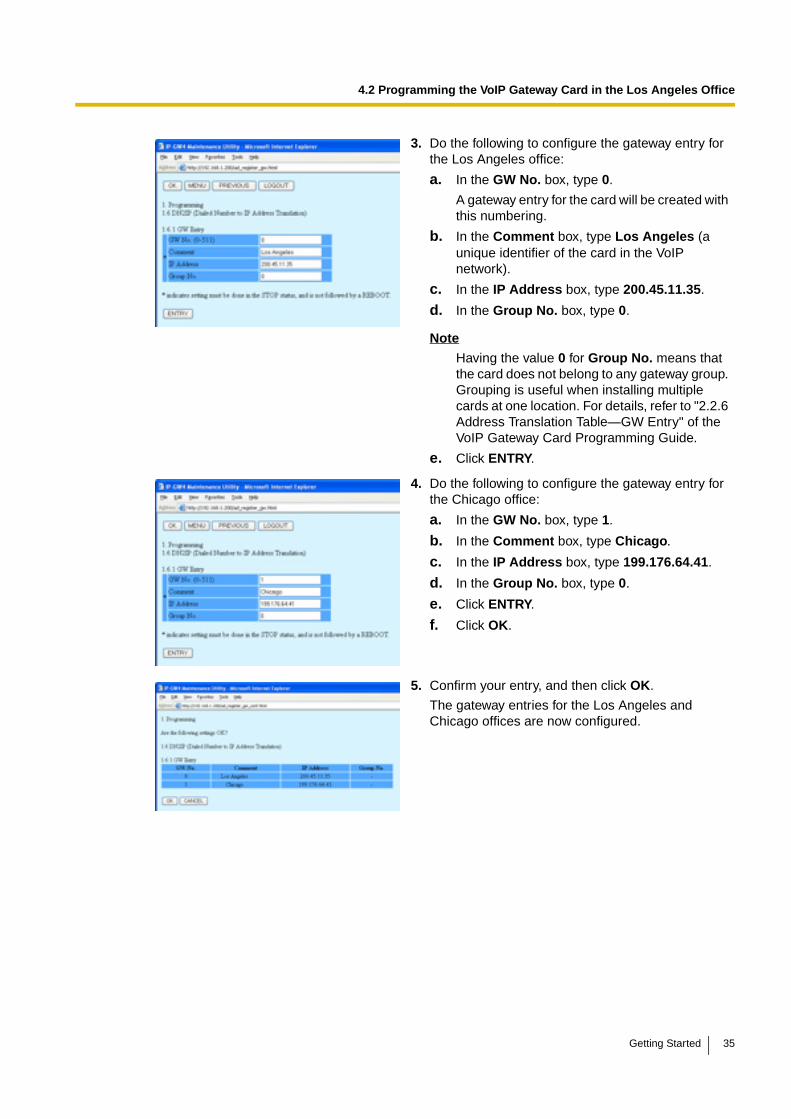
3. Do the following to configure the gateway entry for the Los Angeles office:
a. In the GW No. box, type 0.
A gateway entry for the card will be created with this numbering.
b. In the Comment box, type Los Angeles (a unique identifier of the card in the VoIP network).
c. In the IP Address box, type 200.45.11.35.
d. In the Group No. box, type 0.
Note
Having the value 0 for Group No. means that the card does not belong to any gateway group. Grouping is useful when installing multiple cards at one location. For details, refer to "2.2.6 Address Translation Table—GW Entry" of the VoIP Gateway Card Programming Guide.
e. Click ENTRY.
4. Do the following to configure the gateway entry for the Chicago office:
a. In the GW No. box, type 1.
b. In the Comment box, type Chicago.
c. In the IP Address box, type 199.176.64.41.
d. In the Group No. box, type 0.
e. Click ENTRY.
f. Click OK.
5. Confirm your entry, and then click OK.
The gateway entries for the Los Angeles and Chicago offices are now configured.
Getting Started 35
4.2 Programming the VoIP Gateway Card in the Los Angeles Office
Note
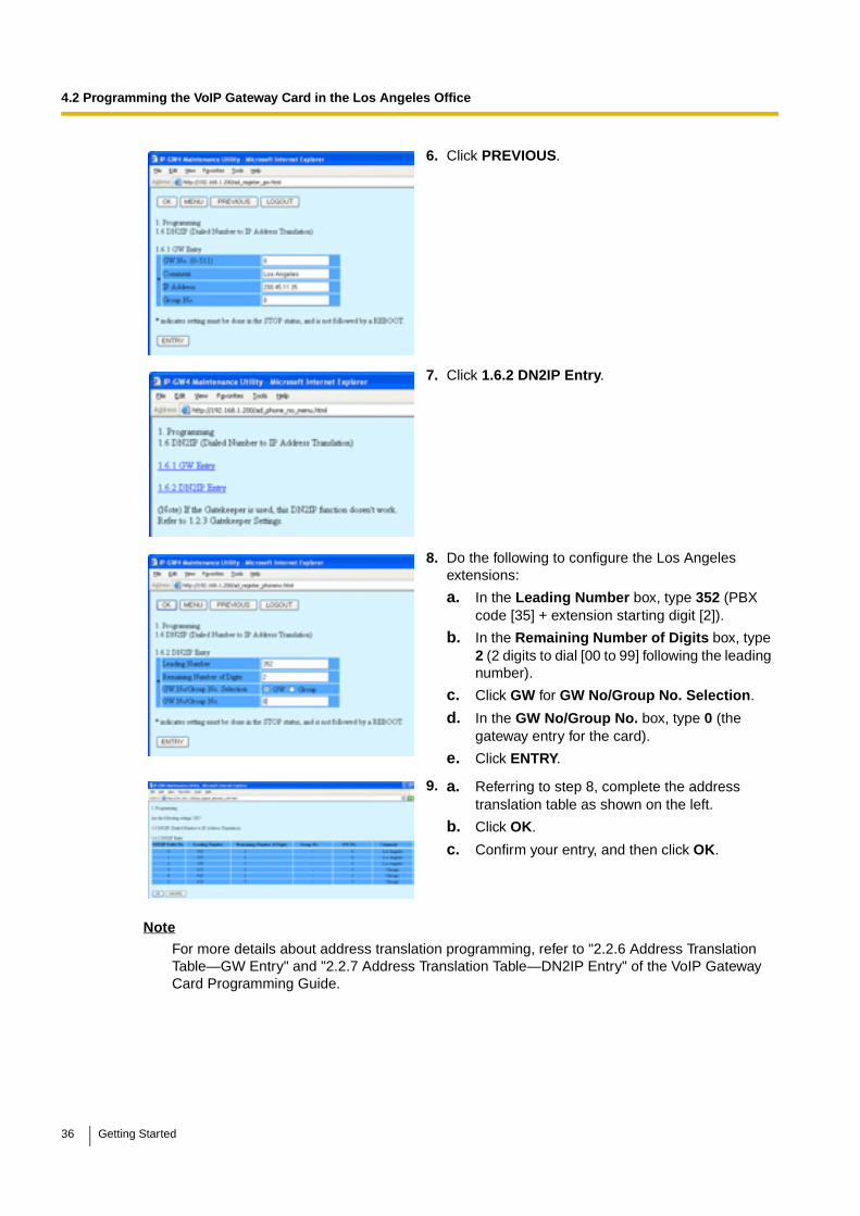
For more details about address translation programming, refer to "2.2.6 Address Translation Table—GW Entry" and "2.2.7 Address Translation Table—DN2IP Entry" of the VoIP Gateway Card Programming Guide.
6. Click PREVIOUS.
7. Click 1.6.2 DN2IP Entry.
8. Do the following to configure the Los Angeles extensions:
a. In the Leading Number box, type 352 (PBX code [35] + extension starting digit [2]).
b. In the Remaining Number of Digits box, type 2 (2 digits to dial [00 to 99] following the leading number).
c. Click GW for GW No/Group No. Selection.
d. In the GW No/Group No. box, type 0 (the gateway entry for the card).
e. Click ENTRY.
9. a. Referring to step 8, complete the address translation table as shown on the left.
b. Click OK.
c. Confirm your entry, and then click OK.
36 Getting Started
4.2 Programming the VoIP Gateway Card in the Los Angeles Office
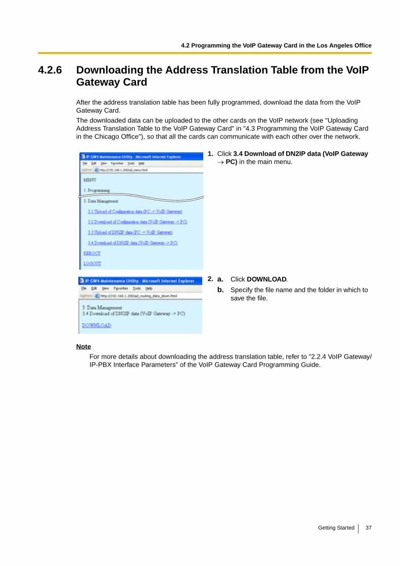
4.2.6 Downloading the Address Translation Table from the VoIP Gateway Card
After the address translation table has been fully programmed, download the data from the VoIP Gateway Card.
The downloaded data can be uploaded to the other cards on the VoIP network (see "Uploading Address Translation Table to the VoIP Gateway Card" in "4.3 Programming the VoIP Gateway Card in the Chicago Office"), so that all the cards can communicate with each other over the network.
Note
For more details about downloading the address translation table, refer to "2.2.4 VoIP Gateway/IP-PBX Interface Parameters" of the VoIP Gateway Card Programming Guide.
1. Click 3.4 Download of DN2IP data (VoIP Gateway → PC) in the main menu.
2. a. Click DOWNLOAD.
b. Specify the file name and the folder in which to save the file.
Getting Started 37
4.2 Programming the VoIP Gateway Card in the Los Angeles Office
4.2.7 Rebooting the VoIP Gateway Card
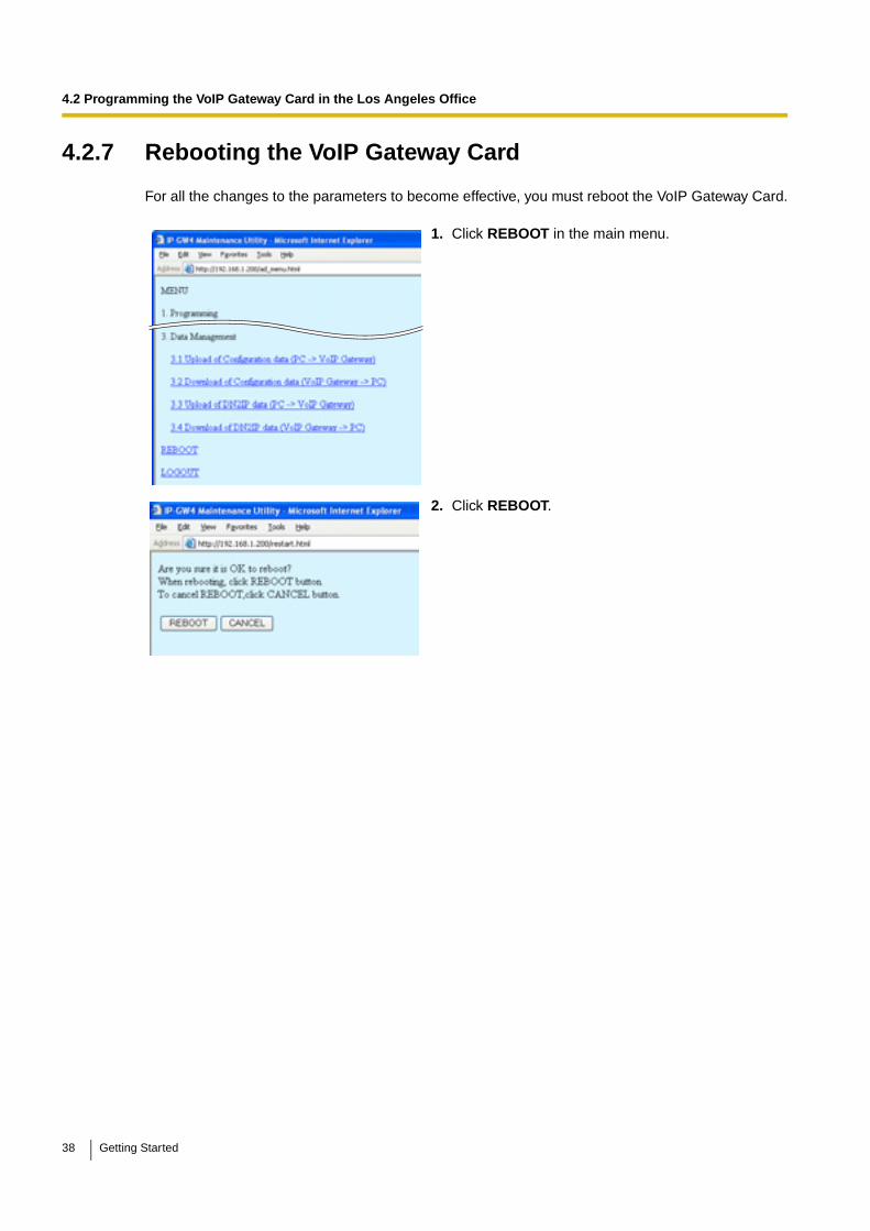
For all the changes to the parameters to become effective, you must reboot the VoIP Gateway Card.
1. Click REBOOT in the main menu.
2. Click REBOOT.
38 Getting Started
4.2 Programming the VoIP Gateway Card in the Los Angeles Office
4.2.8 Confirming the IP Address Assignment
After programming of the VoIP Gateway Card is finished, try to access the card with the new IP addressing information. If you can connect to the card without problems, the card can be placed on the LAN for VoIP operations (see "2.2.2 Connection to the LAN" or "3.2.2 Connection to the LAN").
Follow the procedure below, referring to "4.1.1 Preparing the PC" and "4.2.1 Starting the IP-GW4 Maintenance Utility".
1. Set the IP address settings of the PC to the following values:
• IP address: 200.45.11.100
• Subnet Mask address: 255.255.255.0
2. Start Internet Explorer from the Start menu.
3. In the Address box of Internet Explorer, type http://200.45.11.35 (the new IP address of the card).
4. Press the ENTER key on the keyboard.
If you can log in, then the card has been successfully programmed.
After you have confirmed that the card has been successfully programmed, it is strongly recommended that you download the configuration data from the card and save it on your PC for backup and archive purposes.
The procedure for downloading the configuration data is provided in "2.4.2 Download of Configuration Data" of the VoIP Gateway Card Programming Guide.
Getting Started 39
4.3 Programming the VoIP Gateway Card in the Chicago Office
4.3 Programming the VoIP Gateway Card in the Chicago OfficeThis section details the procedure to programme the VoIP Gateway Card in the Chicago office, which for the most part is a duplication of that for the Los Angeles office. For general information that is not discussed here, refer to the relevant sections in "4.2 Programming the VoIP Gateway Card in the Los Angeles Office".
There are differences in the procedure where distinct setting values are required for parameters that are dependent on the specific network configuration of the Chicago office. Also, the address translation table does not need to be programmed, because the one downloaded from the card in the Los Angeles office already contains the information for the entire network. You can simply upload the address translation table from the Los Angeles office, and the cards can communicate with each other on the network.
Starting the IP-GW4 Maintenance Utility
Changing the Status of the VoIP Gateway Card
1. Start Internet Explorer from the Start menu.
2. a. In the Address box of Internet Explorer, type http://192.168.1.200 (default IP address of the card).
Make sure that the PC has the appropriate IP address setting to access the card (refer to "4.1.1 Preparing the PC").
b. Press the ENTER key on the keyboard.
3. a. In the Username box, type Administrator (default user name).
b. In the Password box, type Administrator (default password).
c. Click LOGIN.
The main menu appears.
1. Click 2.1 Change RUN/STOP status in the main menu.
2. a. Click STOP for Status after changing.
b. Click OK.
c. Click OK.
d. Click OK.
40 Getting Started
4.3 Programming the VoIP Gateway Card in the Chicago Office
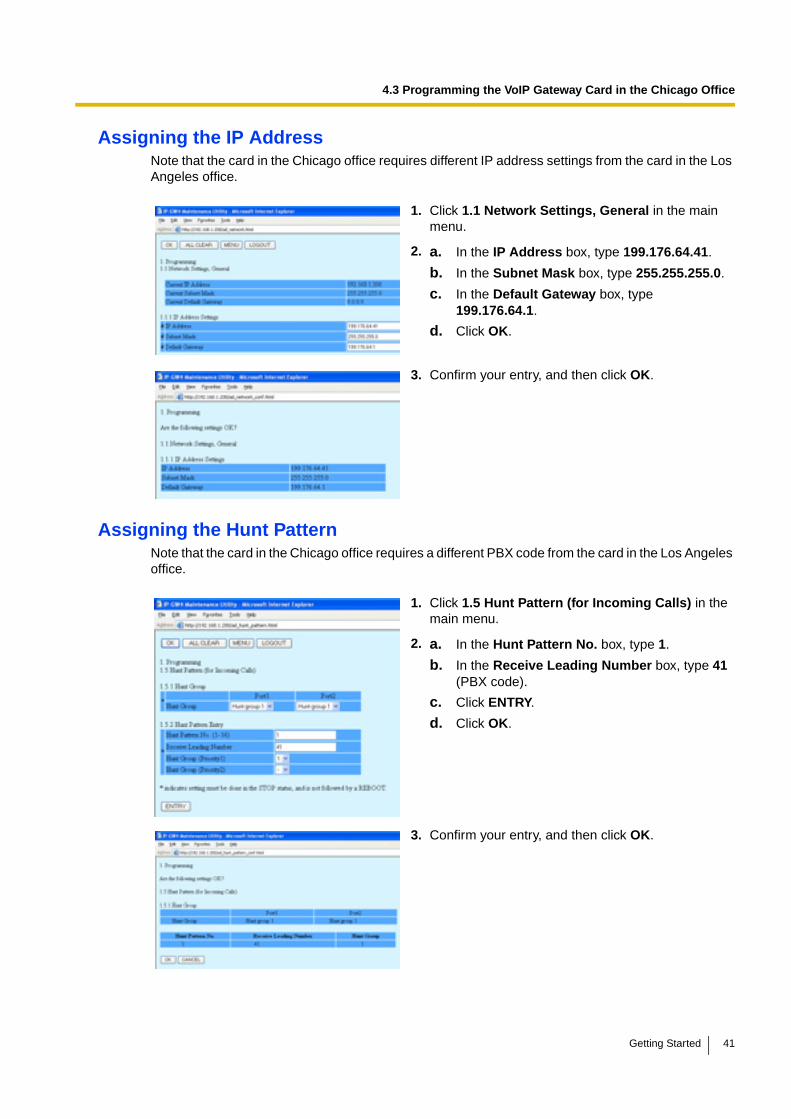
Assigning the IP AddressNote that the card in the Chicago office requires different IP address settings from the card in the Los Angeles office.
Assigning the Hunt PatternNote that the card in the Chicago office requires a different PBX code from the card in the Los Angeles office.
1. Click 1.1 Network Settings, General in the main menu.
2. a. In the IP Address box, type 199.176.64.41.
b. In the Subnet Mask box, type 255.255.255.0.
c. In the Default Gateway box, type 199.176.64.1.
d. Click OK.
3. Confirm your entry, and then click OK.
1. Click 1.5 Hunt Pattern (for Incoming Calls) in the main menu.
2. a. In the Hunt Pattern No. box, type 1.
b. In the Receive Leading Number box, type 41 (PBX code).
c. Click ENTRY.
d. Click OK.
3. Confirm your entry, and then click OK.
Getting Started 41
4.3 Programming the VoIP Gateway Card in the Chicago Office
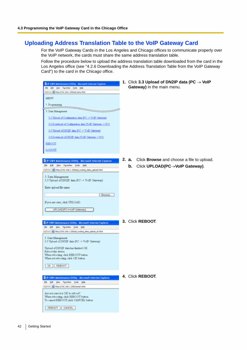
Uploading Address Translation Table to the VoIP Gateway CardFor the VoIP Gateway Cards in the Los Angeles and Chicago offices to communicate properly over the VoIP network, the cards must share the same address translation table.
Follow the procedure below to upload the address translation table downloaded from the card in the Los Angeles office (see "4.2.6 Downloading the Address Translation Table from the VoIP Gateway Card") to the card in the Chicago office.
1. Click 3.3 Upload of DN2IP data (PC → VoIP Gateway) in the main menu.
2. a. Click Browse and choose a file to upload.
b. Click UPLOAD(PC→VoIP Gateway).
3. Click REBOOT.
4. Click REBOOT.
42 Getting Started

4.3 Programming the VoIP Gateway Card in the Chicago Office
Note
For more details about uploading the address translation table, refer to "2.4.3 Upload of Address Translation Table" of the VoIP Gateway Card Programming Guide.
Confirming the IP Address AssignmentNote that the card in the Chicago has been assigned a different IP address from the card in the Los Angeles office.
1. Set the IP address settings of the PC to the following values:
• IP address: 199.176.64.100
• Subnet Mask address: 255.255.255.0
2. Start Internet Explorer from the Start menu.
3. In the Address box of Internet Explorer, type http://199.176.64.41 (the new IP address of the card).
4. Press the ENTER key on the keyboard.
If you can log in, then the card has been successfully programmed.
After you have confirmed that the card has been successfully programmed, it is strongly recommended that you download the configuration data from the card and save it on your PC for backup and archive purposes.
The procedure for downloading the configuration data is provided in "2.4.2 Download of Configuration Data" of the VoIP Gateway Card Programming Guide.
Getting Started 43

4.3 Programming the VoIP Gateway Card in the Chicago Office
44 Getting Started

Section 5
Programming the PBX
For successful operation of a VoIP network using the VoIP Gateway Card as a QSIG network interface, the PBX at each location in the network must be programmed appropriately. For a detailed discussion of related features, refer to the Hybrid IP-PBX Feature Guide.
This section details the procedure to programme the PBX to use the card.
Getting Started 45

5.1 Programming the PBX in the Los Angeles Office
5.1 Programming the PBX in the Los Angeles OfficeThis section details the procedure to programme the PBX in the Los Angeles office using the Maintenance Console (PC programming software of the PBX). After the PBX in the Los Angeles office has been fully programmed, programme the PBX in the Chicago office with the appropriate setting values (see "5.2 Programming the PBX in the Chicago Office").
Notes
• It is assumed that you have already installed the KX-TDA30 Maintenance Console (PC programming software of the KX-TDA30 PBX) in your PC.
• The contents and design of the software are subject to change without notice.
1. Start the KX-TDA30 Maintenance Console from the Start menu.
2. a. Type the Installer Level Programmer Code (default: INSTALLER).
b. Click OK.
3. a. Click Connect → RS-232C or USB.
b. On the next screen, type the system password for installer (default: 1234).
c. Click OK.
The system menu appears.
4. a. Under Configuration, click Slot.
b. Move the mouse pointer over the installed VoIP Gateway Card to display the menu of options.
c. Click Port Property.
Confirm that ports 1 and 2 are in service (INS).
46 Getting Started
5.1 Programming the PBX in the Los Angeles Office
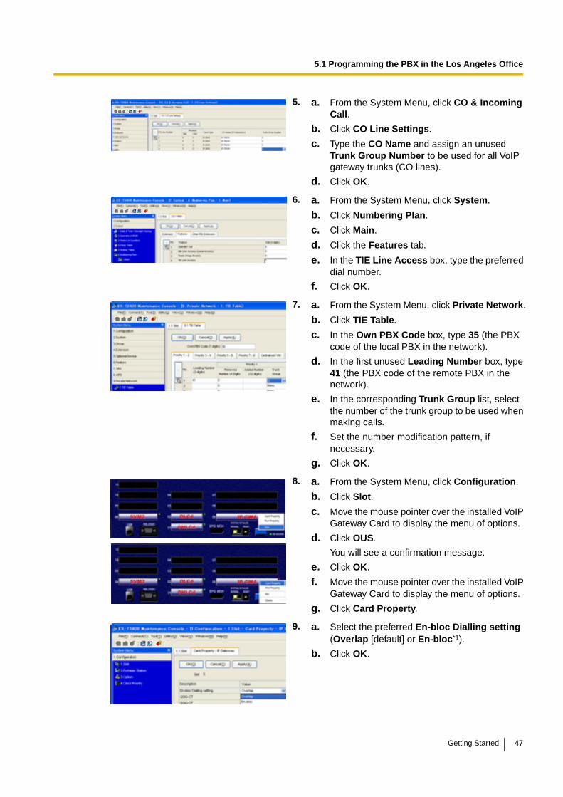
5. a. From the System Menu, click CO & Incoming Call.
b. Click CO Line Settings.
c. Type the CO Name and assign an unused Trunk Group Number to be used for all VoIP gateway trunks (CO lines).
d. Click OK.
6. a. From the System Menu, click System.
b. Click Numbering Plan.
c. Click Main.
d. Click the Features tab.
e. In the TIE Line Access box, type the preferred dial number.
f. Click OK.
7. a. From the System Menu, click Private Network.
b. Click TIE Table.
c. In the Own PBX Code box, type 35 (the PBX code of the local PBX in the network).
d. In the first unused Leading Number box, type 41 (the PBX code of the remote PBX in the network).
e. In the corresponding Trunk Group list, select the number of the trunk group to be used when making calls.
f. Set the number modification pattern, if necessary.
g. Click OK.
8. a. From the System Menu, click Configuration.
b. Click Slot.
c. Move the mouse pointer over the installed VoIP Gateway Card to display the menu of options.
d. Click OUS.
You will see a confirmation message.
e. Click OK.
f. Move the mouse pointer over the installed VoIP Gateway Card to display the menu of options.
g. Click Card Property.
9. a. Select the preferred En-bloc Dialling setting (Overlap [default] or En-bloc*1).
b. Click OK.
Getting Started 47
5.1 Programming the PBX in the Los Angeles Office
Note
For details about network parameter settings, refer to the relevant sections of the Hybrid IP-PBX PC Programming Manual.
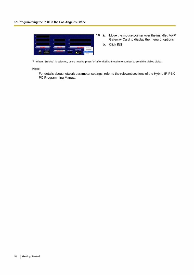
10. a. Move the mouse pointer over the installed VoIP Gateway Card to display the menu of options.
b. Click INS.
*1 When "En-bloc" is selected, users need to press "#" after dialling the phone number to send the dialled digits.
48 Getting Started
5.2 Programming the PBX in the Chicago Office
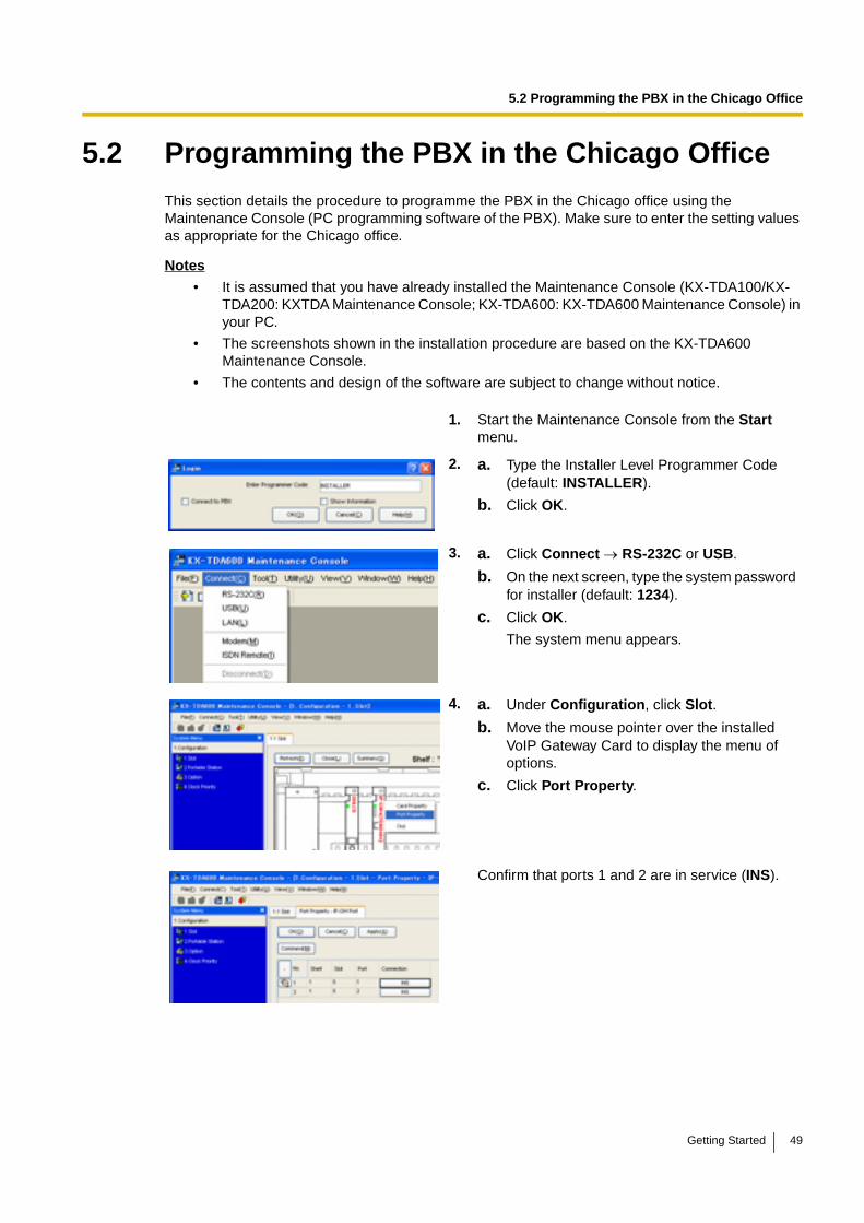
5.2 Programming the PBX in the Chicago OfficeThis section details the procedure to programme the PBX in the Chicago office using the Maintenance Console (PC programming software of the PBX). Make sure to enter the setting values as appropriate for the Chicago office.
Notes
• It is assumed that you have already installed the Maintenance Console (KX-TDA100/KX-TDA200: KXTDA Maintenance Console; KX-TDA600: KX-TDA600 Maintenance Console) in your PC.
• The screenshots shown in the installation procedure are based on the KX-TDA600 Maintenance Console.
• The contents and design of the software are subject to change without notice.
1. Start the Maintenance Console from the Start menu.
2. a. Type the Installer Level Programmer Code (default: INSTALLER).
b. Click OK.
3. a. Click Connect → RS-232C or USB.
b. On the next screen, type the system password for installer (default: 1234).
c. Click OK.
The system menu appears.
4. a. Under Configuration, click Slot.
b. Move the mouse pointer over the installed VoIP Gateway Card to display the menu of options.
c. Click Port Property.
Confirm that ports 1 and 2 are in service (INS).
Getting Started 49
5.2 Programming the PBX in the Chicago Office
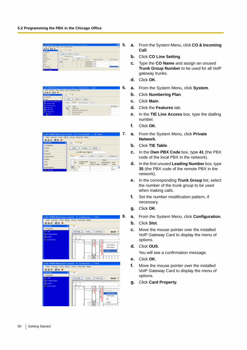
5. a. From the System Menu, click CO & Incoming Call.
b. Click CO Line Setting.
c. Type the CO Name and assign an unused Trunk Group Number to be used for all VoIP gateway trunks.
d. Click OK.
6. a. From the System Menu, click System.
b. Click Numbering Plan.
c. Click Main.
d. Click the Features tab.
e. In the TIE Line Access box, type the dialling number.
f. Click OK.
7. a. From the System Menu, click Private Network.
b. Click TIE Table.
c. In the Own PBX Code box, type 41 (the PBX code of the local PBX in the network).
d. In the first unused Leading Number box, type 35 (the PBX code of the remote PBX in the network).
e. In the corresponding Trunk Group list, select the number of the trunk group to be used when making calls.
f. Set the number modification pattern, if necessary.
g. Click OK.
8. a. From the System Menu, click Configuration.
b. Click Slot.
c. Move the mouse pointer over the installed VoIP Gateway Card to display the menu of options.
d. Click OUS.
You will see a confirmation message.
e. Click OK.
f. Move the mouse pointer over the installed VoIP Gateway Card to display the menu of options.
g. Click Card Property.
50 Getting Started

5.2 Programming the PBX in the Chicago Office
Note
For details about network parameter settings, refer to the relevant sections of the Hybrid IP-PBX PC Programming Manual.
9. a. Select the preferred En-bloc Dialling setting (Overlap [default] or En-bloc*1.
b. Click OK.
10. a. Move the mouse pointer over the installed VoIP Gateway Card to display the menu of options.
b. Click INS.
*1 When "En-bloc" is selected, users need to press "#" after dialling the phone number to enter the dialled digits.
Getting Started 51

5.2 Programming the PBX in the Chicago Office
52 Getting Started
Appendix A
Guidance for VoIP Installation
Getting Started 53
A1 VoIP Requirements
A1 VoIP Requirements
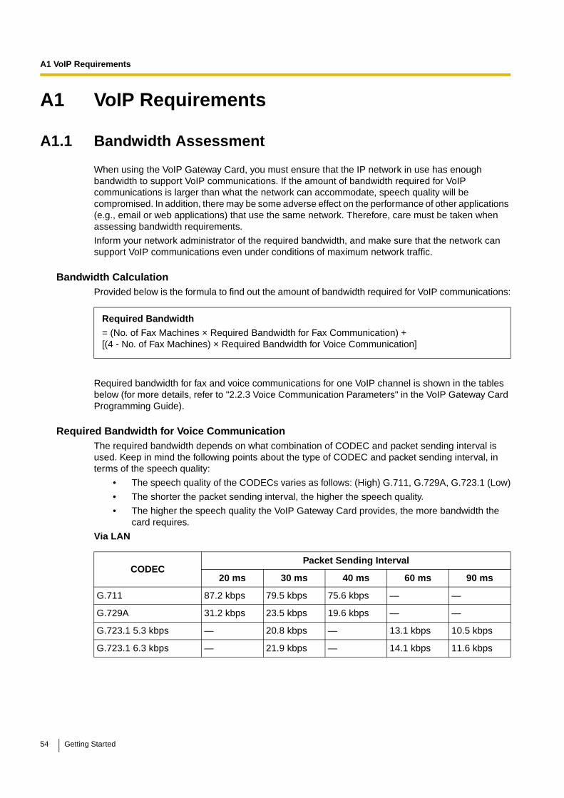
A1.1 Bandwidth Assessment
When using the VoIP Gateway Card, you must ensure that the IP network in use has enough bandwidth to support VoIP communications. If the amount of bandwidth required for VoIP communications is larger than what the network can accommodate, speech quality will be compromised. In addition, there may be some adverse effect on the performance of other applications (e.g., email or web applications) that use the same network. Therefore, care must be taken when assessing bandwidth requirements.
Inform your network administrator of the required bandwidth, and make sure that the network can support VoIP communications even under conditions of maximum network traffic.
Bandwidth CalculationProvided below is the formula to find out the amount of bandwidth required for VoIP communications:
Required bandwidth for fax and voice communications for one VoIP channel is shown in the tables below (for more details, refer to "2.2.3 Voice Communication Parameters" in the VoIP Gateway Card Programming Guide).
Required Bandwidth for Voice CommunicationThe required bandwidth depends on what combination of CODEC and packet sending interval is used. Keep in mind the following points about the type of CODEC and packet sending interval, in terms of the speech quality:
• The speech quality of the CODECs varies as follows: (High) G.711, G.729A, G.723.1 (Low)
• The shorter the packet sending interval, the higher the speech quality.
• The higher the speech quality the VoIP Gateway Card provides, the more bandwidth the card requires.
Via LAN
Required Bandwidth
= (No. of Fax Machines × Required Bandwidth for Fax Communication) +[(4 - No. of Fax Machines) × Required Bandwidth for Voice Communication]
CODECPacket Sending Interval
20 ms 30 ms 40 ms 60 ms 90 ms
G.711 87.2 kbps 79.5 kbps 75.6 kbps — —
G.729A 31.2 kbps 23.5 kbps 19.6 kbps — —
G.723.1 5.3 kbps — 20.8 kbps — 13.1 kbps 10.5 kbps
G.723.1 6.3 kbps — 21.9 kbps — 14.1 kbps 11.6 kbps
54 Getting Started
A1 VoIP Requirements
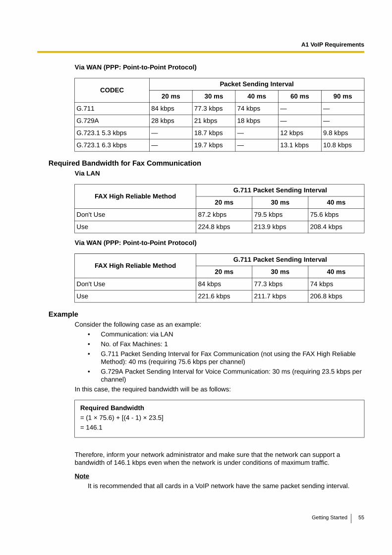
Via WAN (PPP: Point-to-Point Protocol)
Required Bandwidth for Fax CommunicationVia LAN
Via WAN (PPP: Point-to-Point Protocol)
ExampleConsider the following case as an example:
• Communication: via LAN
• No. of Fax Machines: 1
• G.711 Packet Sending Interval for Fax Communication (not using the FAX High Reliable Method): 40 ms (requiring 75.6 kbps per channel)
• G.729A Packet Sending Interval for Voice Communication: 30 ms (requiring 23.5 kbps per channel)
In this case, the required bandwidth will be as follows:
Therefore, inform your network administrator and make sure that the network can support a bandwidth of 146.1 kbps even when the network is under conditions of maximum traffic.
Note
It is recommended that all cards in a VoIP network have the same packet sending interval.
CODECPacket Sending Interval
20 ms 30 ms 40 ms 60 ms 90 ms
G.711 84 kbps 77.3 kbps 74 kbps — —
G.729A 28 kbps 21 kbps 18 kbps — —
G.723.1 5.3 kbps — 18.7 kbps — 12 kbps 9.8 kbps
G.723.1 6.3 kbps — 19.7 kbps — 13.1 kbps 10.8 kbps
FAX High Reliable MethodG.711 Packet Sending Interval
20 ms 30 ms 40 ms
Don't Use 87.2 kbps 79.5 kbps 75.6 kbps
Use 224.8 kbps 213.9 kbps 208.4 kbps
FAX High Reliable MethodG.711 Packet Sending Interval
20 ms 30 ms 40 ms
Don't Use 84 kbps 77.3 kbps 74 kbps
Use 221.6 kbps 211.7 kbps 206.8 kbps
Required Bandwidth
= (1 × 75.6) + [(4 - 1) × 23.5]
= 146.1
Getting Started 55

A1 VoIP Requirements
A1.2 Network Configuration
You must evaluate the structure of the existing network to see if a VoIP network can be implemented. Below are the points that should be taken into your evaluation.
Is it possible to have static IP addressing?Because the maintenance of the VoIP Gateway Card is carried out from a personal computer (PC) through an IP network, the card must be assigned a static IP address.
Static IP addressing must be made possible even when the DHCP feature is used. For more details, refer to "2.2.1 Network Parameters" in the VoIP Gateway Card Programming Guide.
Is network address translation (NAT/NAPT) disabled?In a network where address translation techniques (e.g., NAT/NAPT) are used to convert between global and local IP addresses, VoIP communications based on the H.323 protocol cannot be carried out appropriately. Generally, NAT/NAPT are features that are available with routers.
Note
If the router on the network supports the "H.323 NAT" feature, it may be possible to have VoIP communications over the network. For more information, consult your network administrator.
Router(NAT/NAPT enabled)
IP Network
Global IP Address Domain
Local IP Address Domain
56 Getting Started
A1 VoIP Requirements
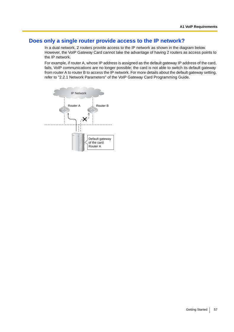
Does only a single router provide access to the IP network?In a dual network, 2 routers provide access to the IP network as shown in the diagram below. However, the VoIP Gateway Card cannot take the advantage of having 2 routers as access points to the IP network.
For example, if router A, whose IP address is assigned as the default gateway IP address of the card, fails, VoIP communications are no longer possible; the card is not able to switch its default gateway from router A to router B to access the IP network. For more details about the default gateway setting, refer to "2.2.1 Network Parameters" of the VoIP Gateway Card Programming Guide.
IP Network
Router A Router B
Default gateway of the card: Router A
Getting Started 57
A1 VoIP Requirements
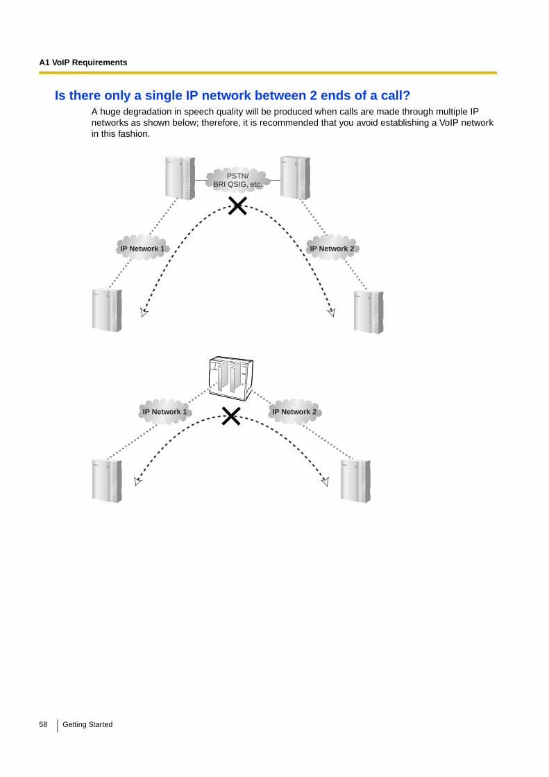
Is there only a single IP network between 2 ends of a call?A huge degradation in speech quality will be produced when calls are made through multiple IP networks as shown below; therefore, it is recommended that you avoid establishing a VoIP network in this fashion.
IP Network 1 IP Network 2
PSTN/BRI QSIG, etc.
IP Network 1 IP Network 2
58 Getting Started

A1 VoIP Requirements
Is the card located appropriately?Transmission delays can cause pauses and loss in VoIP communications. The more network devices (e.g., routers and switches) there are between the communicating cards, the larger the transmission delays, because a certain amount of delay is inevitable when packets go through each network device (hop).
One preventative measure is to install the card so that the number of transmission hops is kept to a minimum. In the diagram below, the card is located as close to the IP network interface as possible.
A1.3 Network Devices
You must evaluate the network devices that are used in the existing network to see if a VoIP network can be implemented. Below are the points that should be taken into your evaluation.
Can the firewall pass packets from the VoIP Gateway Card?If the VoIP network contains a firewall, the firewall must be configured appropriately to allow VoIP packets, which are listed in the table below, to pass through the network without being blocked by filtering.
For more information, consult your network administrator.
Protocol TCP/UDP Default Port No.
HTTP*1 TCP 80
RTP/RTCP*2 UDP 5004 to 5011
H.225.0 Call Signalling*2 TCP 1720
H.245*2 TCP 1712 to 1724
H.225.0 RAS*2 UDP 1719
QSIG Connectionless Tunnelling*1 TCP 1718
Router
Switch
Too many hops
Switch
Hub
Router
Switch
Better(PBX located nearest IP network access point)
Switch
Hub
Getting Started 59

A1 VoIP Requirements
Are layer 2 or higher switches used?Use of repeater hubs can increase the network load, and therefore will result in degradation in speech quality.
To ensure high speech quality, it is strongly recommended that you use layer 2 or higher switches.
Are Category 5 (CAT5) cables used?When connecting network devices, make sure to use CAT5 cables. If other types of cables are used, communications may not be carried out normally.
A1.4 QoS (Quality of Service)
Some routers permit the configuration of priority control features. This allows the router to give higher priority to voice packets and lower the rate of loss and delays during transmissions, hence improving speech quality. It is strongly recommended that you use this feature, especially in networks where traffic is heavy.
Typically, a router identifies what packets to pass in priority by checking the value in the ToS field of the header of IP packets. The VoIP Gateway Card has the ability to set the ToS field of outgoing voice packets (see "2.2.3 Voice Communication Parameters" in the VoIP Gateway Card Programming Guide). When the card is appropriately configured, the router can give voice packets from the card higher priority.
Consult your network administrator when setting the ToS field, as the setting value must conform to the router's specifications.
NoteSome switches also permit the configuration of priority control features. For more information, consult your network administrator.
*1 For the actual setting values, refer to "2.2.1 Network Parameters" in the VoIP Gateway Card Programming Guide.
*2 For the actual setting values, refer to "2.2.2 H.323 Parameters" in the VoIP Gateway Card Programming Guide.
60 Getting Started
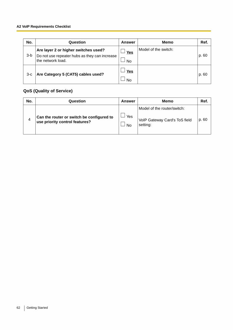
A2 VoIP Requirements Checklist
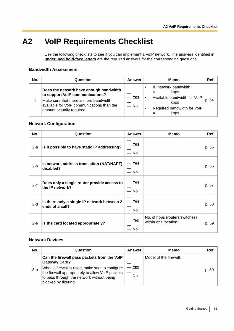
A2 VoIP Requirements ChecklistUse the following checklists to see if you can implement a VoIP network. The answers identified in underlined bold-face letters are the required answers for the corresponding questions.
Bandwidth Assessment
Network Configuration
Network Devices
No. Question Answer Memo Ref.
1
Does the network have enough bandwidth to support VoIP communications?
Make sure that there is more bandwidth available for VoIP communications than the amount actually required.
Yes
No
• IP network bandwidth= kbps
• Available bandwidth for VoIP= kbps
• Required bandwidth for VoIP= kbps
p. 54
No. Question Answer Memo Ref.
2-a Is it possible to have static IP addressing? Yes
No
p. 56
2-bIs network address translation (NAT/NAPT) disabled?
Yes
No
p. 56
2-cDoes only a single router provide access to the IP network?
Yes
No
p. 57
2-dIs there only a single IP network between 2 ends of a call?
Yes
No
p. 58
2-e Is the card located appropriately? Yes
No
No. of hops (routers/switches) within one location: p. 59
No. Question Answer Memo Ref.
3-a
Can the firewall pass packets from the VoIP Gateway Card?
When a firewall is used, make sure to configure the firewall appropriately to allow VoIP packets to pass through the network without being blocked by filtering.
Yes
No
Model of the firewall:
p. 59
Getting Started 61
A2 VoIP Requirements Checklist
QoS (Quality of Service)
3-bAre layer 2 or higher switches used?
Do not use repeater hubs as they can increase the network load.
Yes
No
Model of the switch:
p. 60
3-c Are Category 5 (CAT5) cables used? Yes
No
p. 60
No. Question Answer Memo Ref.
4Can the router or switch be configured to use priority control features?
Yes
No
Model of the router/switch:
VoIP Gateway Card's ToS field setting:
p. 60
No. Question Answer Memo Ref.
62 Getting Started

Appendix B
Alternative Numbering Plan Example
Getting Started 63
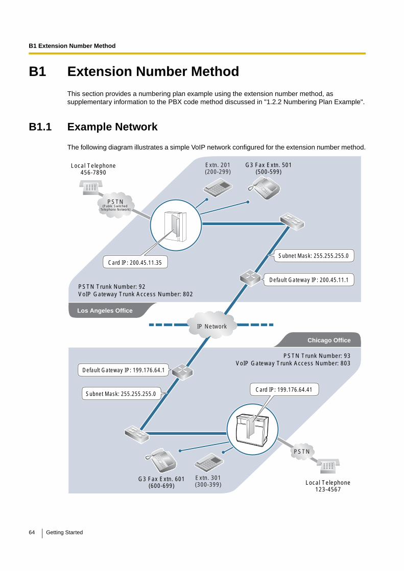
B1 Extension Number Method
B1 Extension Number MethodThis section provides a numbering plan example using the extension number method, as supplementary information to the PBX code method discussed in "1.2.2 Numbering Plan Example".
B1.1 Example Network
The following diagram illustrates a simple VoIP network configured for the extension number method.
PSTN(Public Switched
Telephone Network)
IP Network
Chicago Office
PSTN Trunk Number: 93VoIP Gateway Trunk Access Number: 803
PSTN
Local Telephone123-4567
Extn. 301(300-399)
PSTN Trunk Number: 92VoIP Gateway Trunk Access Number: 802
Extn. 201(200-299)
Local Telephone456-7890
G3 Fax Extn. 501(500-599)
G3 Fax Extn. 601(600-699)
Default Gateway IP: 200.45.11.1
Subnet Mask: 255.255.255.0Card IP: 200.45.11.35
Subnet Mask: 255.255.255.0
Los Angeles Office
Default Gateway IP: 199.176.64.1
Card IP: 199.176.64.41
64 Getting Started
B1 Extension Number Method
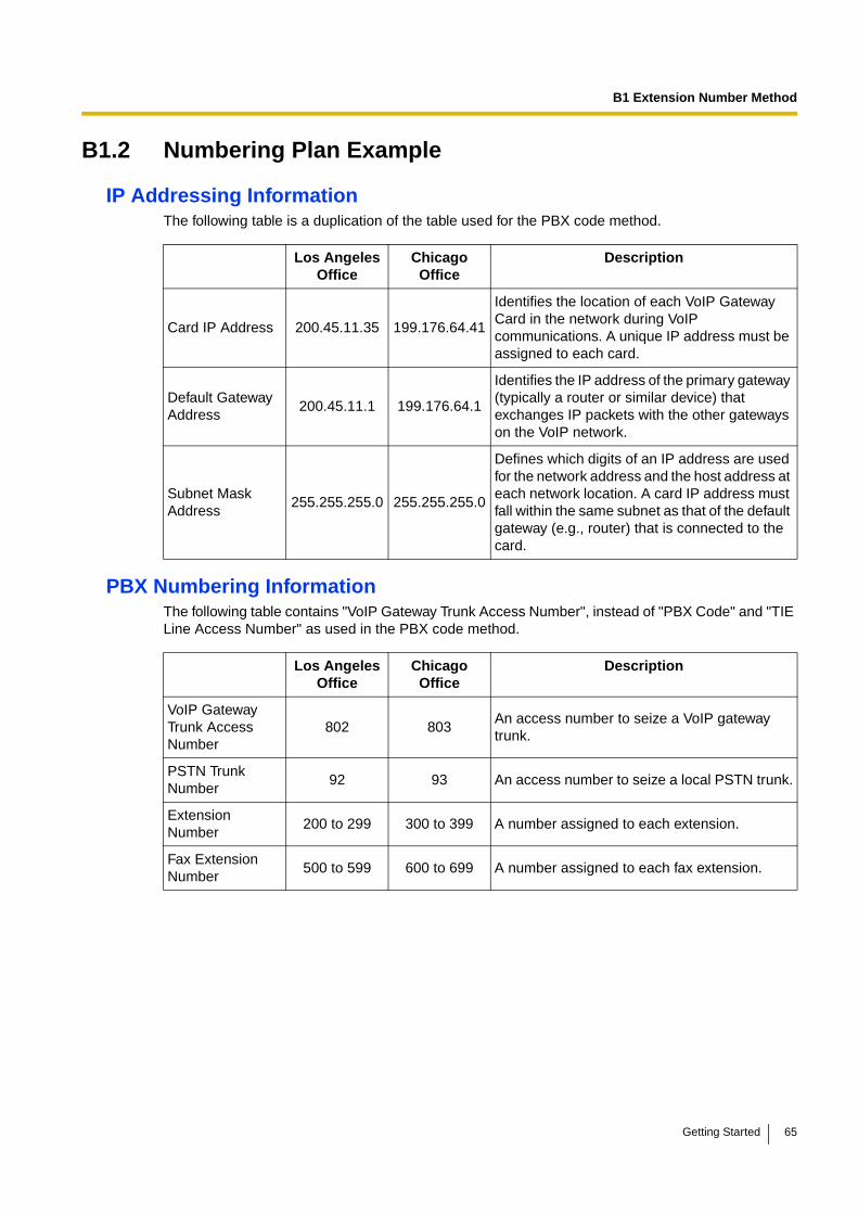
B1.2 Numbering Plan Example
IP Addressing InformationThe following table is a duplication of the table used for the PBX code method.
PBX Numbering InformationThe following table contains "VoIP Gateway Trunk Access Number", instead of "PBX Code" and "TIE Line Access Number" as used in the PBX code method.
Los Angeles Office
Chicago Office
Description
Card IP Address 200.45.11.35 199.176.64.41
Identifies the location of each VoIP Gateway Card in the network during VoIP communications. A unique IP address must be assigned to each card.
Default Gateway Address
200.45.11.1 199.176.64.1
Identifies the IP address of the primary gateway (typically a router or similar device) that exchanges IP packets with the other gateways on the VoIP network.
Subnet Mask Address
255.255.255.0 255.255.255.0
Defines which digits of an IP address are used for the network address and the host address at each network location. A card IP address must fall within the same subnet as that of the default gateway (e.g., router) that is connected to the card.
Los Angeles Office
Chicago Office
Description
VoIP Gateway Trunk Access Number
802 803An access number to seize a VoIP gateway trunk.
PSTN Trunk Number
92 93 An access number to seize a local PSTN trunk.
Extension Number
200 to 299 300 to 399 A number assigned to each extension.
Fax Extension Number
500 to 599 600 to 699 A number assigned to each fax extension.
Getting Started 65
B1 Extension Number Method
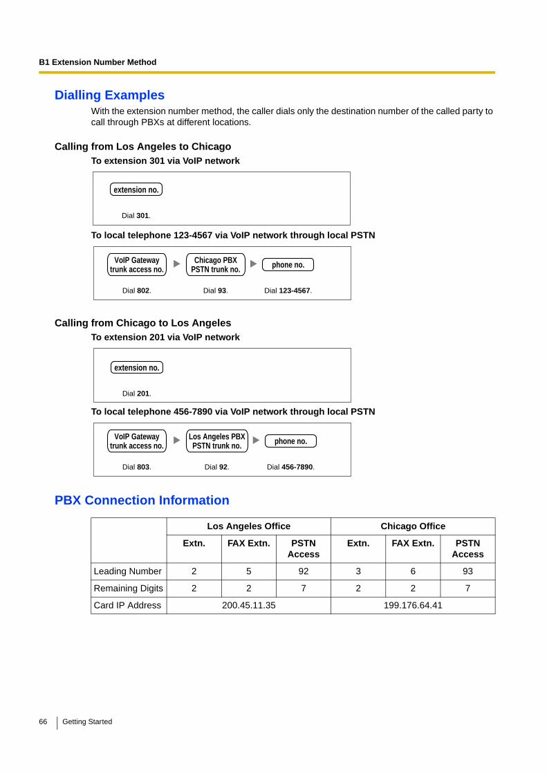
Dialling ExamplesWith the extension number method, the caller dials only the destination number of the called party to call through PBXs at different locations.
Calling from Los Angeles to ChicagoTo extension 301 via VoIP network
To local telephone 123-4567 via VoIP network through local PSTN
Calling from Chicago to Los AngelesTo extension 201 via VoIP network
To local telephone 456-7890 via VoIP network through local PSTN
PBX Connection Information
Los Angeles Office Chicago Office
Extn. FAX Extn. PSTN Access
Extn. FAX Extn. PSTN Access
Leading Number 2 5 92 3 6 93
Remaining Digits 2 2 7 2 2 7
Card IP Address 200.45.11.35 199.176.64.41
Dial 301.
extension no.
Dial 93.Dial 802. Dial 123-4567.
VoIP Gatewaytrunk access no. phone no.Chicago PBX
PSTN trunk no.
Dial 201.
extension no.
Dial 92.Dial 803. Dial 456-7890.
VoIP Gatewaytrunk access no. phone no.Los Angeles PBX
PSTN trunk no.
66 Getting Started
B2 Programming for the Extension Number Method
B2 Programming for the Extension Number MethodWhen programming the VoIP Gateway Cards and PBXs for use in a network configured for the extension number method instead of the PBX code method, some of the steps in the programming procedures require different setting values.
The following 2 sections provide specific steps that require different setting values. The steps other than those provided here have common setting values, and are therefore omitted from this explanation.
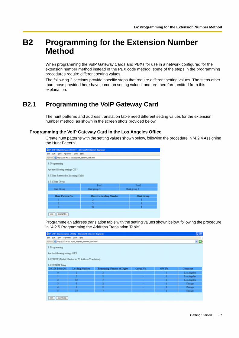
B2.1 Programming the VoIP Gateway Card
The hunt patterns and address translation table need different setting values for the extension number method, as shown in the screen shots provided below.
Programming the VoIP Gateway Card in the Los Angeles OfficeCreate hunt patterns with the setting values shown below, following the procedure in "4.2.4 Assigning the Hunt Pattern".
Programme an address translation table with the setting values shown below, following the procedure in "4.2.5 Programming the Address Translation Table".
Getting Started 67

B2 Programming for the Extension Number Method
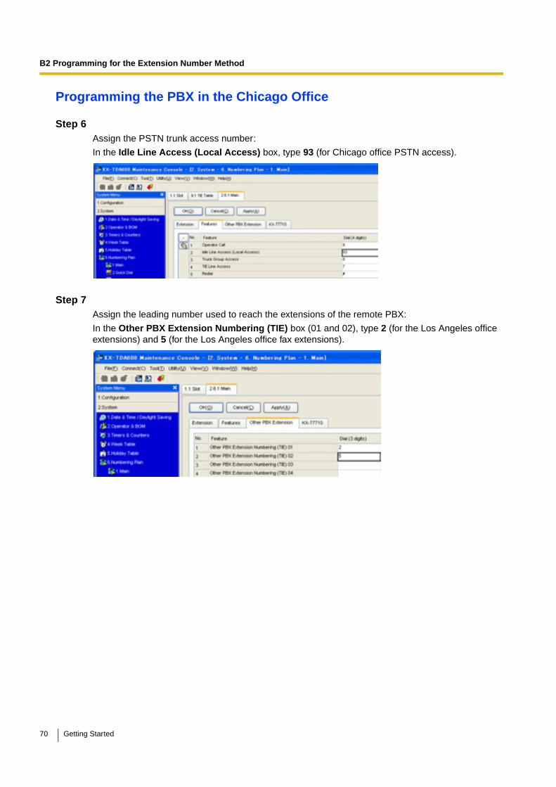
Programming the VoIP Gateway Card in the Chicago OfficeCreate hunt patterns with the setting values shown below, following the procedure in "Assigning the Hunt Pattern" under "4.3 Programming the VoIP Gateway Card in the Chicago Office".
B2.2 Programming the PBX
The steps below are provided in substitution for steps 6 and 7 of the procedure detailed in "5.1 Programming the PBX in the Los Angeles Office" and "5.2 Programming the PBX in the Chicago Office". Programme the PBXs in both offices using the extension number method, following these steps.
Programming the PBX in the Los Angeles Office
Step 6Assign the PSTN trunk access number:
In the Idle Line Access (Local Access) box, type 92 (for Los Angeles office PSTN access).
68 Getting Started
B2 Programming for the Extension Number Method
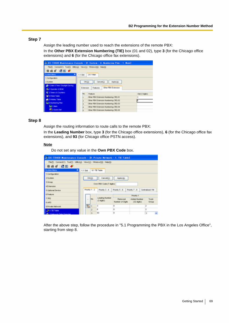
Step 7Assign the leading number used to reach the extensions of the remote PBX:
In the Other PBX Extension Numbering (TIE) box (01 and 02), type 3 (for the Chicago office extensions) and 6 (for the Chicago office fax extensions).
Step 8Assign the routing information to route calls to the remote PBX:
In the Leading Number box, type 3 (for the Chicago office extensions), 6 (for the Chicago office fax extensions), and 93 (for Chicago office PSTN access).
Note
Do not set any value in the Own PBX Code box.
After the above step, follow the procedure in "5.1 Programming the PBX in the Los Angeles Office", starting from step 8.
Getting Started 69
B2 Programming for the Extension Number Method
Programming the PBX in the Chicago Office
Step 6Assign the PSTN trunk access number:
In the Idle Line Access (Local Access) box, type 93 (for Chicago office PSTN access).
Step 7Assign the leading number used to reach the extensions of the remote PBX:
In the Other PBX Extension Numbering (TIE) box (01 and 02), type 2 (for the Los Angeles office extensions) and 5 (for the Los Angeles office fax extensions).
70 Getting Started
B2 Programming for the Extension Number Method
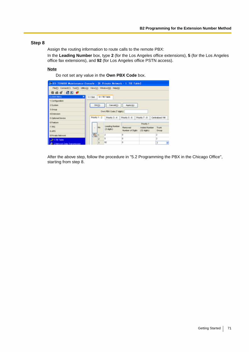
Step 8Assign the routing information to route calls to the remote PBX:
In the Leading Number box, type 2 (for the Los Angeles office extensions), 5 (for the Los Angeles office fax extensions), and 92 (for Los Angeles office PSTN access).
Note
Do not set any value in the Own PBX Code box.
After the above step, follow the procedure in "5.2 Programming the PBX in the Chicago Office", starting from step 8.
Getting Started 71

B2 Programming for the Extension Number Method
72 Getting Started
Appendix C
Initialisation of the VoIP Gateway Card
Getting Started 73
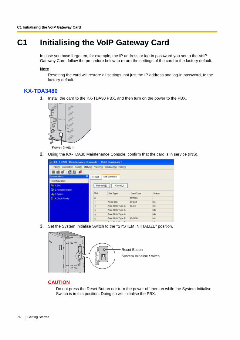
C1 Initialising the VoIP Gateway Card
C1 Initialising the VoIP Gateway CardIn case you have forgotten, for example, the IP address or log-in password you set to the VoIP Gateway Card, follow the procedure below to return the settings of the card to the factory default.
Note
Resetting the card will restore all settings, not just the IP address and log-in password, to the factory default.
KX-TDA34801. Install the card to the KX-TDA30 PBX, and then turn on the power to the PBX.
2. Using the KX-TDA30 Maintenance Console, confirm that the card is in service (INS).
3. Set the System Initialise Switch to the "SYSTEM INITIALIZE" position.
CAUTIONDo not press the Reset Button nor turn the power off then on while the System Initialise Switch is in this position. Doing so will initialise the PBX.
Power Switch
Reset Button
System Initialise Switch
74 Getting Started

C1 Initialising the VoIP Gateway Card
4. Using the KX-TDA30 Maintenance Console, set the status of the card to OUS, then set it back to INS.
5. Return the System Initialise Switch to the "NORMAL" position.
KX-TDA04841. Install the card to the KX-TDA100/KX-TDA200/KX-TDA600 PBX, and then turn on the power to
the PBX.
2. Using the Maintenance Console, confirm that the card is in service (INS).
3. Set the System Initialise Switch to the "SYSTEM INITIALIZE" position.
CAUTIONDo not press the Reset Button nor turn the power off then on while the System Initialise Switch is in this position. Doing so will initialise the PBX.
4. Using the Maintenance Console, set the status of the card to OUS, then set it back to INS.
5. Return the System Initialise Switch to the "NORMAL" position.
Power Switch
System Initialise Switch
Reset Button
SYSTEMINITIALIZE
RESET
NORMAL
Getting Started 75

C1 Initialising the VoIP Gateway Card
76 Getting Started
Appendix D
Using the KX-TDA3480/KX-TDA0484 and KX-TDA0480 in One Network
Getting Started 77
D1 Considerations in Installation
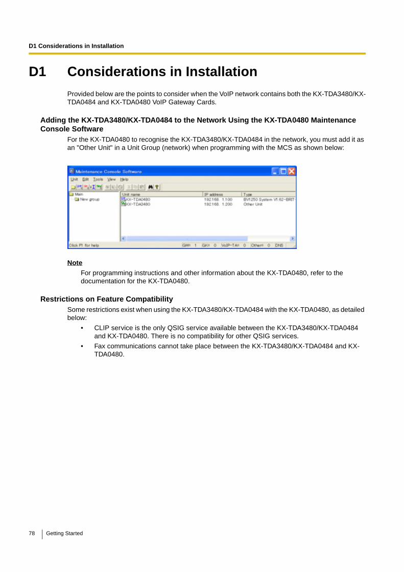
D1 Considerations in InstallationProvided below are the points to consider when the VoIP network contains both the KX-TDA3480/KX-TDA0484 and KX-TDA0480 VoIP Gateway Cards.
Adding the KX-TDA3480/KX-TDA0484 to the Network Using the KX-TDA0480 Maintenance Console Software
For the KX-TDA0480 to recognise the KX-TDA3480/KX-TDA0484 in the network, you must add it as an "Other Unit" in a Unit Group (network) when programming with the MCS as shown below:
Note
For programming instructions and other information about the KX-TDA0480, refer to the documentation for the KX-TDA0480.
Restrictions on Feature CompatibilitySome restrictions exist when using the KX-TDA3480/KX-TDA0484 with the KX-TDA0480, as detailed below:
• CLIP service is the only QSIG service available between the KX-TDA3480/KX-TDA0484 and KX-TDA0480. There is no compatibility for other QSIG services.
• Fax communications cannot take place between the KX-TDA3480/KX-TDA0484 and KX-TDA0480.
78 Getting Started

D1 Considerations in Installation
Getting Started 79

Panasonic Communications Co., Ltd.1-62, 4-chome, Minoshima, Hakata-ku, Fukuoka 812-8531, Japan
Copyright:This material is copyrighted by Panasonic Communications Co., Ltd., and may be reproduced for internal use only. All other reproduction, in whole or in part, is prohibited without the written consent of Panasonic Communications Co., Ltd.
© 2005 Panasonic Communications Co., Ltd. All Rights Reserved.
PSQX3951YA KK0805AH1076

KX-TDA3480 Model KX-TDA0484
4-Channel VoIP Gateway Card
Programming Guide
Thank you for purchasing a Panasonic 4-Channel VoIP Gateway Card.Please read this manual carefully before using this product and save this manual for future use.
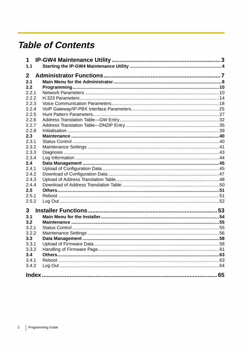
Table of Contents1 IP-GW4 Maintenance Utility ................................................................... 31.1 Starting the IP-GW4 Maintenance Utility ........................................................................4
2 Administrator Functions........................................................................ 72.1 Main Menu for the Administrator.....................................................................................82.2 Programming...................................................................................................................102.2.1 Network Parameters .........................................................................................................102.2.2 H.323 Parameters .............................................................................................................142.2.3 Voice Communication Parameters ....................................................................................182.2.4 VoIP Gateway/IP-PBX Interface Parameters.....................................................................252.2.5 Hunt Pattern Parameters...................................................................................................272.2.6 Address Translation Table—GW Entry..............................................................................322.2.7 Address Translation Table—DN2IP Entry .........................................................................352.2.8 Initialisation .......................................................................................................................392.3 Maintenance ....................................................................................................................402.3.1 Status Control ...................................................................................................................402.3.2 Maintenance Settings .......................................................................................................412.3.3 Diagnosis ..........................................................................................................................432.3.4 Log Information .................................................................................................................442.4 Data Management ...........................................................................................................452.4.1 Upload of Configuration Data............................................................................................452.4.2 Download of Configuration Data .......................................................................................472.4.3 Upload of Address Translation Table.................................................................................482.4.4 Download of Address Translation Table ............................................................................502.5 Others...............................................................................................................................512.5.1 Reboot ..............................................................................................................................512.5.2 Log Out .............................................................................................................................52
3 Installer Functions................................................................................ 533.1 Main Menu for the Installer.............................................................................................543.2 Maintenance ....................................................................................................................553.2.1 Status Control ...................................................................................................................553.2.2 Maintenance Settings .......................................................................................................563.3 Data Management ...........................................................................................................583.3.1 Upload of Firmware Data ..................................................................................................583.3.2 Handling of Firmware Page...............................................................................................613.4 Others...............................................................................................................................633.4.1 Reboot ..............................................................................................................................633.4.2 Log Out .............................................................................................................................64
Index ............................................................................................................ 65
2 Programming Guide

Section 1
IP-GW4 Maintenance Utility
Programming of the VoIP Gateway Card is carried out through a web programming utility called the IP-GW4 Maintenance Utility. This section provides the start-up procedure for the IP-GW4 Maintenance Utility.
Programming Guide 3
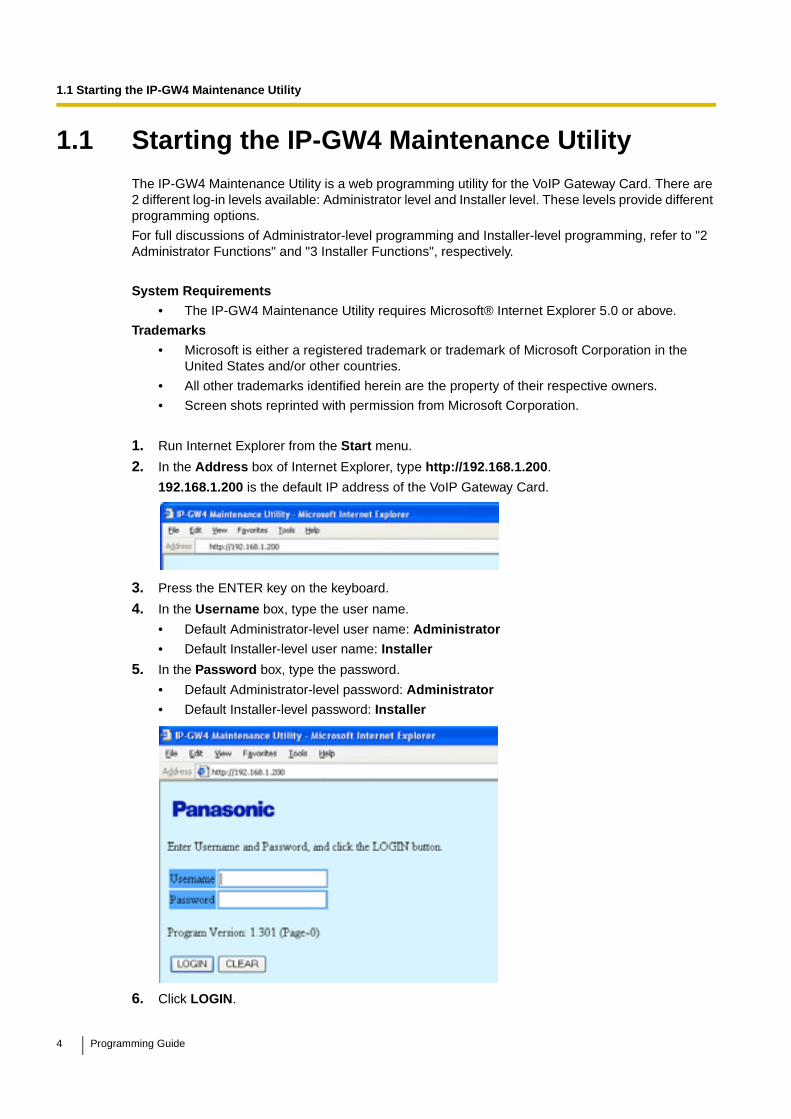
1.1 Starting the IP-GW4 Maintenance Utility
1.1 Starting the IP-GW4 Maintenance UtilityThe IP-GW4 Maintenance Utility is a web programming utility for the VoIP Gateway Card. There are 2 different log-in levels available: Administrator level and Installer level. These levels provide different programming options.
For full discussions of Administrator-level programming and Installer-level programming, refer to "2 Administrator Functions" and "3 Installer Functions", respectively.
System Requirements
• The IP-GW4 Maintenance Utility requires Microsoft® Internet Explorer 5.0 or above.
Trademarks
• Microsoft is either a registered trademark or trademark of Microsoft Corporation in the United States and/or other countries.
• All other trademarks identified herein are the property of their respective owners.
• Screen shots reprinted with permission from Microsoft Corporation.
1. Run Internet Explorer from the Start menu.
2. In the Address box of Internet Explorer, type http://192.168.1.200.
192.168.1.200 is the default IP address of the VoIP Gateway Card.
3. Press the ENTER key on the keyboard.
4. In the Username box, type the user name.
• Default Administrator-level user name: Administrator
• Default Installer-level user name: Installer
5. In the Password box, type the password.
• Default Administrator-level password: Administrator
• Default Installer-level password: Installer
6. Click LOGIN.
4 Programming Guide
1.1 Starting the IP-GW4 Maintenance Utility
To clear your entry, click CLEAR.
Notes• If another user is already logged in, you will be rejected.
• For readability of the text on the screen, it is recommended that you adjust the text size of Internet Explorer to below medium.
• If you finish a programming session without logging out from the card (e.g., quitting Internet Explorer, or returning to the log-in screen with the "Back" button of Internet Explorer), you cannot log in again for the period of time specified by the parameter Programming Auto Disconnect Time (default: 10 min).For the log-out procedure and Programming Auto Disconnect Time setting, refer to "2.5.2 Log Out"/"3.4.2 Log Out" and "2.3.2 Maintenance Settings", respectively.
Programming Guide 5

1.1 Starting the IP-GW4 Maintenance Utility
6 Programming Guide
Section 2
Administrator Functions
This section provides operating instructions for the IP-GW4 Maintenance Utility when logged in as the Administrator.
Programming Guide 7

2.1 Main Menu for the Administrator
2.1 Main Menu for the AdministratorThe IP-GW4 Maintenance Utility provides the following menu to a user logged in as the Administrator.
8 Programming Guide

2.1 Main Menu for the Administrator
Programming
Maintenance
Data Management
Others
Menu Section Reference
1.1 Network Settings, General 2.2.1 Network Parameters
1.2 H.323 Detailed Settings 2.2.2 H.323 Parameters
1.3 Voice Communication Detailed Settings 2.2.3 Voice Communication Parameters
1.4 VoIP Gateway/IP-PBX Interface Settings 2.2.4 VoIP Gateway/IP-PBX Interface Parameters
1.5 Hunt Pattern (for Incoming Calls) 2.2.5 Hunt Pattern Parameters
1.6 DN2IP (Dialed Number to IP Address Translation)
2.2.6 Address Translation Table—GW Entry
2.2.7 Address Translation Table—DN2IP Entry
1.7 Initialization 2.2.8 Initialisation
Menu Section Reference
2.1 Change RUN/STOP status 2.3.1 Status Control
2.2 Maintenance Settings 2.3.2 Maintenance Settings
2.3 Diagnosis 2.3.3 Diagnosis
2.4 Log Information 2.3.4 Log Information
Menu Section Reference
3.1 Upload of Configuration data (PC → VoIP Gateway)
2.4.1 Upload of Configuration Data
3.2 Download of Configuration data (VoIP Gateway → PC)
2.4.2 Download of Configuration Data
3.3 Upload of DN2IP data (PC → VoIP Gateway)
2.4.3 Upload of Address Translation Table
3.4 Download of DN2IP data (VoIP Gateway → PC)
2.4.4 Download of Address Translation Table
Menu Section Reference
REBOOT 2.5.1 Reboot
LOGOUT 2.5.2 Log Out
Programming Guide 9

2.2 Programming
2.2 Programming
2.2.1 Network Parameters
1. Click 1.1 Network Settings, General in the main menu.
Current IP Address, Current Subnet Mask, and Current Default Gateway show the current IP address settings of the VoIP Gateway Card.
2. Assign each parameter referring to the descriptions below.
At any time during the session, you can:
• Click ALL CLEAR to return all parameters to their previous values.
• Click MENU to return to the main menu (see "2.1 Main Menu for the Administrator").
• Click LOGOUT to log out from the IP-GW4 Maintenance Utility (see "2.5.2 Log Out").
3. Click OK.
You will see a confirmation screen.
NoteIf your entry contains an invalid value, you will be prompted to correct your input. Enter correct values for the parameters shown in red and try again.
4. Confirm your entry and click OK.
To return to the previous screen, click CANCEL.
10 Programming Guide
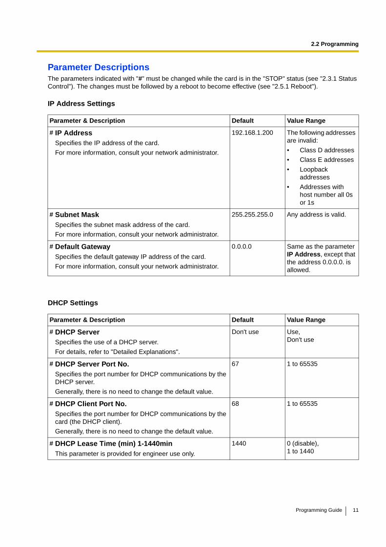
2.2 Programming
Parameter DescriptionsThe parameters indicated with "#" must be changed while the card is in the "STOP" status (see "2.3.1 Status Control"). The changes must be followed by a reboot to become effective (see "2.5.1 Reboot").
IP Address Settings
DHCP Settings
Parameter & Description Default Value Range
# IP AddressSpecifies the IP address of the card.
For more information, consult your network administrator.
192.168.1.200 The following addresses are invalid:
• Class D addresses
• Class E addresses
• Loopback addresses
• Addresses with host number all 0s or 1s
# Subnet MaskSpecifies the subnet mask address of the card.
For more information, consult your network administrator.
255.255.255.0 Any address is valid.
# Default GatewaySpecifies the default gateway IP address of the card.
For more information, consult your network administrator.
0.0.0.0 Same as the parameter IP Address, except that the address 0.0.0.0. is allowed.
Parameter & Description Default Value Range
# DHCP ServerSpecifies the use of a DHCP server.
For details, refer to "Detailed Explanations".
Don't use Use,Don't use
# DHCP Server Port No.Specifies the port number for DHCP communications by the DHCP server.
Generally, there is no need to change the default value.
67 1 to 65535
# DHCP Client Port No.Specifies the port number for DHCP communications by the card (the DHCP client).
Generally, there is no need to change the default value.
68 1 to 65535
# DHCP Lease Time (min) 1-1440minThis parameter is provided for engineer use only.
1440 0 (disable),1 to 1440
Programming Guide 11

2.2 Programming
HTTP Settings
QSIG Connectionless Tunneling Settings
Others
Parameter & Description Default Value Range
# HTTP Port No.Specifies the port number for HTTP communications by the card.
Generally, there is no need to change the default value.
80 1 to 65535
Parameter & Description Default Value Range
# QSIG Connectionless Tunneling Port No.Specifies the port number for connectionless tunnelling between cards at different locations in a QSIG network.
Generally, there is no need to change the default value.
Notes• Connectionless tunnelling enables the PBXs on a
QSIG network to use enhanced networking features. (For more information about these features, refer to the relevant sections of the Hybrid IP-PBX documentation.)
• If you are using a gatekeeper, and enhanced networking features of the PBX are being used, overall performance of the card may deteriorate when network traffic is heavy.
• If you are using a gatekeeper, and "Routed" is specified for the parameter Call Signaling Model (see "2.2.2 H.323 Parameters"), connectionless tunnelling is not possible. In this case, the PBX cannot use the enhanced networking features.
1718 1 to 65535
Parameter & Description Default Value Range
Host NameThis parameter is provided for engineer use only.
VoIP + lower 3 bytes of the MAC address
Max. 255 characters
# LAN Disconnect Threshold Time (s)Specifies the time (in seconds) until disconnection from the LAN is recognised.
For example, even if a LAN cable is disconnected during a call, reconnecting the cable within this time period maintains the call.
5 1 to 10
12 Programming Guide
2.2 Programming
Detailed Explanations
DHCP ServerWhen using the DHCP feature, the IP address settings of the card (IP address, subnet mask, and default gateway) will be assigned by a DHCP server.
However, keep in mind that the maintenance of the card is performed through a web browser from a PC; hence you must know the IP address of the card. Therefore, it is necessary to set up the DHCP server to assign a static IP address to the card from a pool of IP addresses that is defined in advance. For more information about DHCP server settings, consult your network administrator.
In addition, it is also necessary to specify the values for the parameters under IP Address Settings as they will be assigned by the DHCP server.
Programming Guide 13
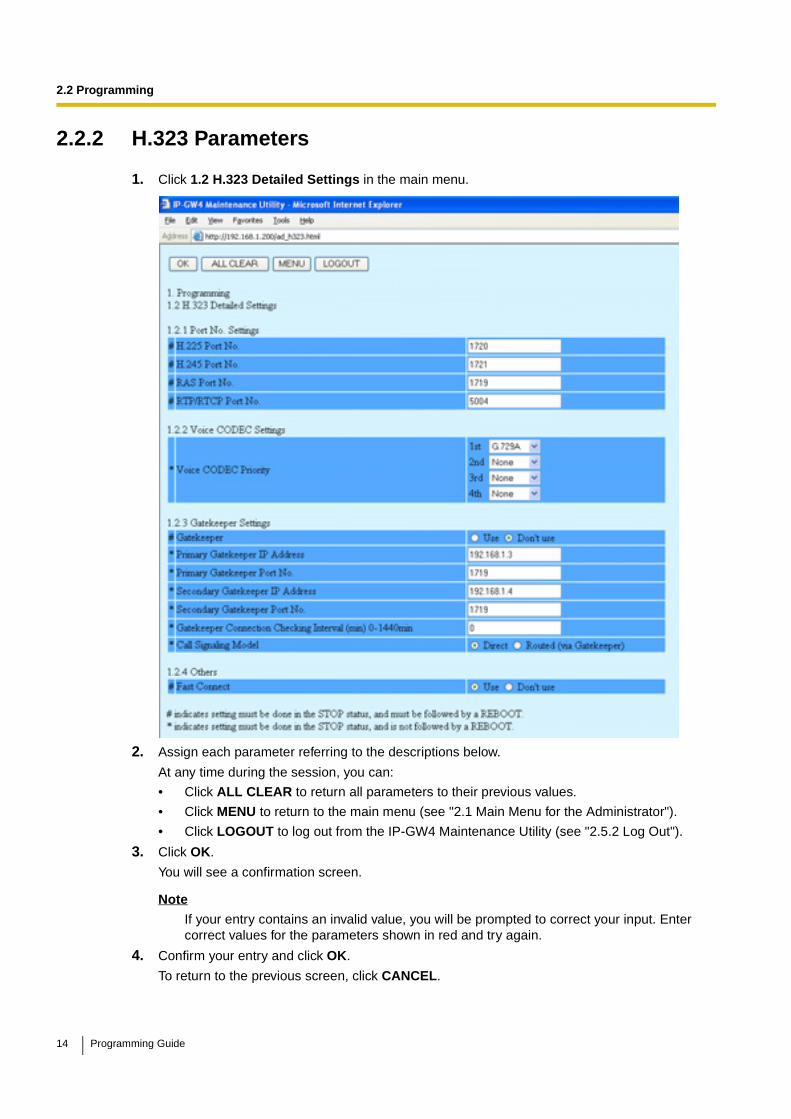
2.2 Programming
2.2.2 H.323 Parameters
1. Click 1.2 H.323 Detailed Settings in the main menu.
2. Assign each parameter referring to the descriptions below.
At any time during the session, you can:
• Click ALL CLEAR to return all parameters to their previous values.
• Click MENU to return to the main menu (see "2.1 Main Menu for the Administrator").
• Click LOGOUT to log out from the IP-GW4 Maintenance Utility (see "2.5.2 Log Out").
3. Click OK.
You will see a confirmation screen.
Note
If your entry contains an invalid value, you will be prompted to correct your input. Enter correct values for the parameters shown in red and try again.
4. Confirm your entry and click OK.
To return to the previous screen, click CANCEL.
14 Programming Guide

2.2 Programming
Parameter DescriptionsThe parameters indicated with "#" must be changed while the VoIP Gateway Card is in the "STOP" status (see "2.3.1 Status Control"). The changes must be followed by a reboot to become effective (see "2.5.1 Reboot").
The parameters indicated with "*" must be changed while the card is in the "STOP" status (see "2.3.1 Status Control"). The changes do not have to be followed by a reboot to become effective.
Port Number Settings
Voice CODEC Settings
Parameter & Description Default Value Range
# H.225 Port No.Specifies the port number for the H.225 protocol (call control) in an H.323 protocol suite.
Generally, there is no need to change the default value.
1720 1 to 65535
# H.245 Port No.Specifies the port number for the H.245 protocol (negotiation of channel usage and capabilities) in an H.323 protocol suite. 4 consecutive ports, starting with the specified port, will be used (by default, 1721 to 1724).
Generally, there is no need to change the default value.
1721 1 to 65532
# RAS Port No.Specifies the port number for the H.225 protocol (RAS) in an H.323 protocol suite.
Generally, there is no need to change the default value.
1719 1 to 65535
# RTP/RTCP Port No.Specifies the port number for RTP/RTCP. 8 consecutive ports, starting with the specified port, will be used (by default, 5004 to 5011).
Generally, there is no need to change the default value.
5004 1 to 65528
Parameter & Description Default Value Range
* Voice CODEC Priority 1st–4thSpecifies the type of CODEC for voice communications.
Choose the appropriate CODEC for the network environment (e.g., bandwidth, CODEC conditions of the remote terminal). When using multiple CODECs, set them in an appropriate priority order.
Prior to establishing a call, a negotiation takes place over the network and the CODEC to be used will be decided depending on the setting of this parameter.
For details about relations between bandwidth and CODEC, refer to "Detailed Explanations" in "2.2.3 Voice Communication Parameters".
1st: G.729A2nd: No default3rd: No default4th: No default
G.723.1,G.729A,G.711Mu,G.711A
Programming Guide 15
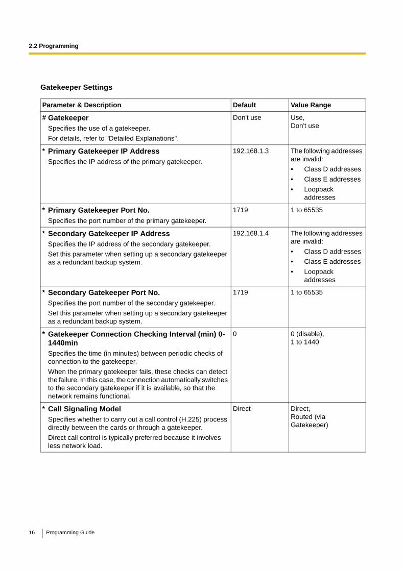
2.2 Programming
Gatekeeper Settings
Parameter & Description Default Value Range
# GatekeeperSpecifies the use of a gatekeeper.
For details, refer to "Detailed Explanations".
Don't use Use,Don't use
* Primary Gatekeeper IP AddressSpecifies the IP address of the primary gatekeeper.
192.168.1.3 The following addresses are invalid:
• Class D addresses
• Class E addresses
• Loopback addresses
* Primary Gatekeeper Port No.Specifies the port number of the primary gatekeeper.
1719 1 to 65535
* Secondary Gatekeeper IP AddressSpecifies the IP address of the secondary gatekeeper.
Set this parameter when setting up a secondary gatekeeper as a redundant backup system.
192.168.1.4 The following addresses are invalid:
• Class D addresses
• Class E addresses
• Loopback addresses
* Secondary Gatekeeper Port No.Specifies the port number of the secondary gatekeeper.
Set this parameter when setting up a secondary gatekeeper as a redundant backup system.
1719 1 to 65535
* Gatekeeper Connection Checking Interval (min) 0-1440minSpecifies the time (in minutes) between periodic checks of connection to the gatekeeper.
When the primary gatekeeper fails, these checks can detect the failure. In this case, the connection automatically switches to the secondary gatekeeper if it is available, so that the network remains functional.
0 0 (disable),1 to 1440
* Call Signaling ModelSpecifies whether to carry out a call control (H.225) process directly between the cards or through a gatekeeper.
Direct call control is typically preferred because it involves less network load.
Direct Direct,Routed (via Gatekeeper)
16 Programming Guide
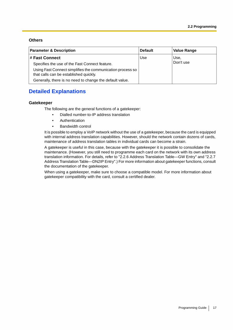
2.2 Programming
Others
Detailed Explanations
GatekeeperThe following are the general functions of a gatekeeper:
• Dialled number-to-IP address translation
• Authentication
• Bandwidth control
It is possible to employ a VoIP network without the use of a gatekeeper, because the card is equipped with internal address translation capabilities. However, should the network contain dozens of cards, maintenance of address translation tables in individual cards can become a strain.
A gatekeeper is useful in this case, because with the gatekeeper it is possible to consolidate the maintenance. (However, you still need to programme each card on the network with its own address translation information. For details, refer to "2.2.6 Address Translation Table—GW Entry" and "2.2.7 Address Translation Table—DN2IP Entry".) For more information about gatekeeper functions, consult the documentation of the gatekeeper.
When using a gatekeeper, make sure to choose a compatible model. For more information about gatekeeper compatibility with the card, consult a certified dealer.
Parameter & Description Default Value Range
# Fast ConnectSpecifies the use of the Fast Connect feature.
Using Fast Connect simplifies the communication process so that calls can be established quickly.
Generally, there is no need to change the default value.
Use Use,Don't use
Programming Guide 17
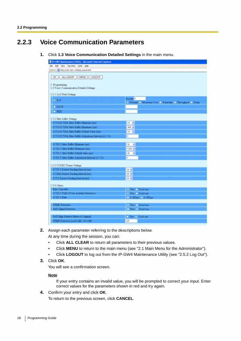
2.2 Programming
2.2.3 Voice Communication Parameters
1. Click 1.3 Voice Communication Detailed Settings in the main menu.
2. Assign each parameter referring to the descriptions below.
At any time during the session, you can:
• Click ALL CLEAR to return all parameters to their previous values.
• Click MENU to return to the main menu (see "2.1 Main Menu for the Administrator").
• Click LOGOUT to log out from the IP-GW4 Maintenance Utility (see "2.5.2 Log Out").
3. Click OK.
You will see a confirmation screen.
NoteIf your entry contains an invalid value, you will be prompted to correct your input. Enter correct values for the parameters shown in red and try again.
4. Confirm your entry and click OK.
To return to the previous screen, click CANCEL.
18 Programming Guide
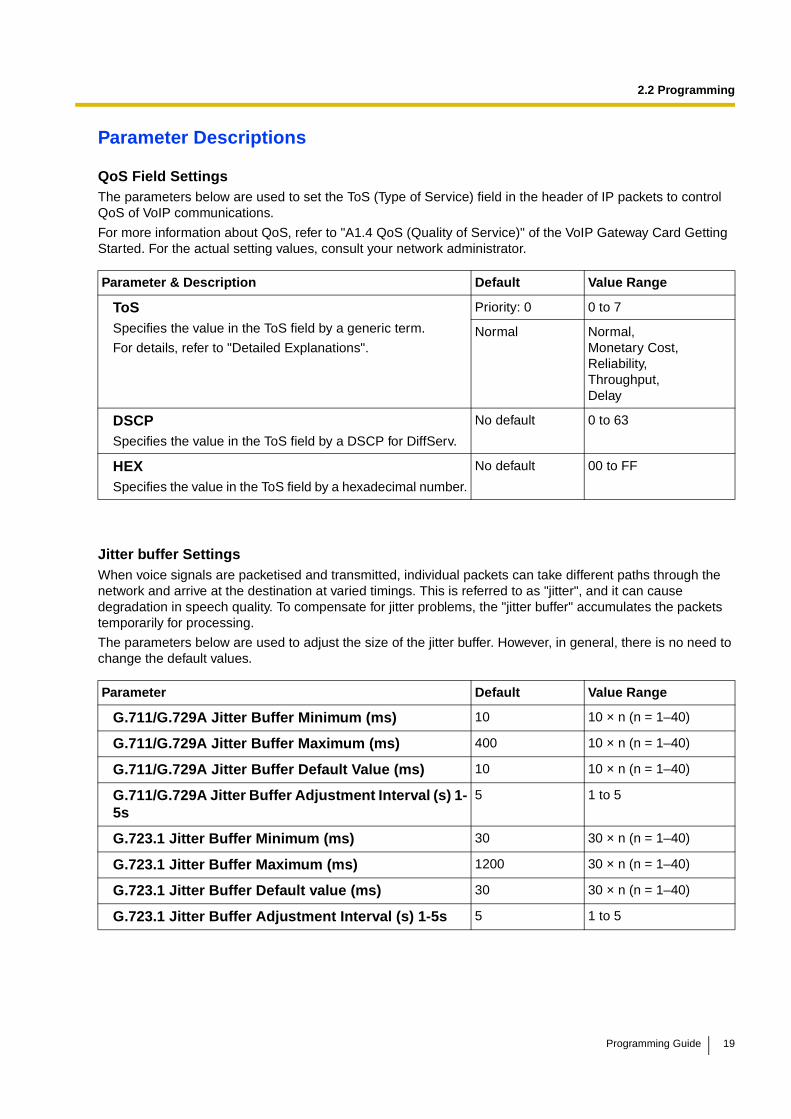
2.2 Programming
Parameter Descriptions
QoS Field SettingsThe parameters below are used to set the ToS (Type of Service) field in the header of IP packets to control QoS of VoIP communications.
For more information about QoS, refer to "A1.4 QoS (Quality of Service)" of the VoIP Gateway Card Getting Started. For the actual setting values, consult your network administrator.
Jitter buffer SettingsWhen voice signals are packetised and transmitted, individual packets can take different paths through the network and arrive at the destination at varied timings. This is referred to as "jitter", and it can cause degradation in speech quality. To compensate for jitter problems, the "jitter buffer" accumulates the packets temporarily for processing.
The parameters below are used to adjust the size of the jitter buffer. However, in general, there is no need to change the default values.
Parameter & Description Default Value Range
ToSSpecifies the value in the ToS field by a generic term.
For details, refer to "Detailed Explanations".
Priority: 0 0 to 7
Normal Normal,Monetary Cost,Reliability,Throughput,Delay
DSCPSpecifies the value in the ToS field by a DSCP for DiffServ.
No default 0 to 63
HEXSpecifies the value in the ToS field by a hexadecimal number.
No default 00 to FF
Parameter Default Value Range
G.711/G.729A Jitter Buffer Minimum (ms) 10 10 × n (n = 1–40)
G.711/G.729A Jitter Buffer Maximum (ms) 400 10 × n (n = 1–40)
G.711/G.729A Jitter Buffer Default Value (ms) 10 10 × n (n = 1–40)
G.711/G.729A Jitter Buffer Adjustment Interval (s) 1-5s
5 1 to 5
G.723.1 Jitter Buffer Minimum (ms) 30 30 × n (n = 1–40)
G.723.1 Jitter Buffer Maximum (ms) 1200 30 × n (n = 1–40)
G.723.1 Jitter Buffer Default value (ms) 30 30 × n (n = 1–40)
G.723.1 Jitter Buffer Adjustment Interval (s) 1-5s 5 1 to 5
Programming Guide 19

2.2 Programming
CODEC Frame SettingsThe parameters below are used to set the interval between packet transmissions for each type of CODEC. It is recommended that all VoIP Gateway Cards in a VoIP network have the same settings for these parameters.
For details, refer to "Detailed Explanations".
Others
Parameter Default Value Range
G.723.1 Packet Sending Interval (ms) 30 30, 60, 90
G.729A Packet Sending Interval (ms) 20 20, 30, 40
G.711 Packet Sending Interval (ms) 20 20, 30, 40
Parameter & Description Default Value Range
Echo CancellerSpecifies the use of the echo cancellation feature (G.168).
Echo is the audible duplication of a caller's voice on the return path; when echo exists, the caller hears his or her own voice after some delay. The echo canceller eliminates this echo.
NoteThere are various factors that may cause an echo. In some cases, this feature does not eliminate the echo entirely.
Use Use,Don't use
G.723.1 VAD (Voice Activity Detection)Specifies the use of the VAD feature (G.723.1).
The VAD conserves bandwidth by detecting silent periods during a call and suppressing the packets of silence from being sent to the network.
Note
To use this feature, both the local and remote cards must have this parameter set to "Use".
Use Use,Don't use
G.723.1 RateSpecifies the rate of the G.723.1 CODEC.
6.3Kbps 5.3Kbps,6.3Kbps
DTMF Detection Specifies the use of the DTMF detection feature.
DTMF detection enables end-to-end DTMF relay over the network.
For details, refer to "Detailed Explanations".
Use Use,Don't use
FAX Signal DetectionSpecifies the use of the fax signal detection feature.
Fax signal detection enables end-to-end fax signal relay over the network.
For details, refer to "Detailed Explanations".
Don't use Use,Don't use
20 Programming Guide
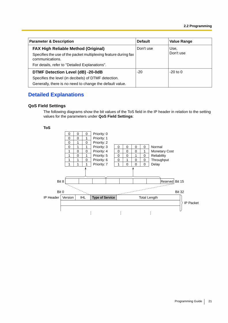
2.2 Programming
Detailed Explanations
QoS Field SettingsThe following diagrams show the bit values of the ToS field in the IP header in relation to the setting values for the parameters under QoS Field Settings:
ToS
FAX High Reliable Method (Original)Specifies the use of the packet multiplexing feature during fax communications.
For details, refer to "Detailed Explanations".
Don't use Use,Don't use
DTMF Detection Level (dB) -20-0dBSpecifies the level (in decibels) of DTMF detection.
Generally, there is no need to change the default value.
-20 -20 to 0
Parameter & Description Default Value Range
....
....
....
Bit 0
Bit 8
IP Header Version IHL Total Length
00001111
00110011
01010101
Priority: 0Priority: 1Priority: 2Priority: 3Priority: 4Priority: 5Priority: 6Priority: 7
Bit 15Reserved
Bit 32
IP Packet
Type of Service
00001
00010
00100
01000
NormalMonetary CostReliabilityThroughputDelay
Programming Guide 21

2.2 Programming
DSCP
HEX
CODEC Frame SettingsThe amount of required bandwidth depends on the type of CODEC and the selected packet sending interval. The tables below show the amount of bandwidth required for one VoIP channel in each case:
Required Bandwidth for Voice Communication via LAN
CODECPacket Sending Interval
20 ms 30 ms 40 ms 60 ms 90 ms
G.711 87.2 kbps 79.5 kbps 75.6 kbps — —
G.729A 31.2 kbps 23.5 kbps 19.6 kbps — —
G.723.1 5.3 kbps — 20.8 kbps — 13.1 kbps 10.5 kbps
G.723.1 6.3 kbps — 21.9 kbps — 14.1 kbps 11.6 kbps
....
....
....
Bit 0
Bit 8
IP Header Version IHL Total Length
Bit 15ReservedReserved
Bit 32
IP Packet
Type of Service
DSCP: 0DSCP: 1
DSCP: 62DSCP: 63
00
11
00
11
00
11
00
11
00
11
01
01
....
....
....
....
....
....
....
....
....
Bit 0
Bit 8
IP Header Version IHL Total Length
Bit 15
Bit 32
IP Packet
Type of Service
HEX: 0HEX: 1
HEX: FEHEX: FF
00
11
00
11
00
11
00
11
00
11
00
11
00
11
01
01
....
....
....
....
....
....
....
....
22 Programming Guide
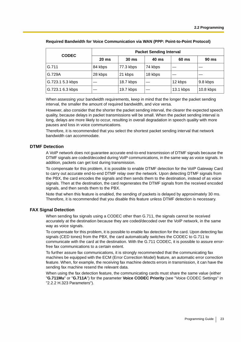
2.2 Programming
Required Bandwidth for Voice Communication via WAN (PPP: Point-to-Point Protocol)
When assessing your bandwidth requirements, keep in mind that the longer the packet sending interval, the smaller the amount of required bandwidth, and vice versa.
However, also consider that the shorter the packet sending interval, the clearer the expected speech quality, because delays in packet transmissions will be small. When the packet sending interval is long, delays are more likely to occur, resulting in overall degradation in speech quality with more pauses and loss in voice communications.
Therefore, it is recommended that you select the shortest packet sending interval that network bandwidth can accommodate.
DTMF DetectionA VoIP network does not guarantee accurate end-to-end transmission of DTMF signals because the DTMF signals are coded/decoded during VoIP communications, in the same way as voice signals. In addition, packets can get lost during transmission.
To compensate for this problem, it is possible to enable DTMF detection for the VoIP Gateway Card to carry out accurate end-to-end DTMF relay over the network. Upon detecting DTMF signals from the PBX, the card encodes the signals and then sends them to the destination, instead of as voice signals. Then at the destination, the card regenerates the DTMF signals from the received encoded signals, and then sends them to the PBX.
Note that when this feature is enabled, the sending of packets is delayed by approximately 30 ms. Therefore, it is recommended that you disable this feature unless DTMF detection is necessary.
FAX Signal DetectionWhen sending fax signals using a CODEC other than G.711, the signals cannot be received accurately at the destination because they are coded/decoded over the VoIP network, in the same way as voice signals.
To compensate for this problem, it is possible to enable fax detection for the card. Upon detecting fax signals (CED tones) from the PBX, the card automatically switches the CODEC to G.711 to communicate with the card at the destination. With the G.711 CODEC, it is possible to assure error-free fax communications to a certain extent.
To further assure fax communications, it is strongly recommended that the communicating fax machines be equipped with the ECM (Error Correction Model) feature, an automatic error correction feature. When, for example, the receiving fax machine detects errors in transmission, it can have the sending fax machine resend the relevant data.
When using the fax detection feature, the communicating cards must share the same value (either "G.711Mu" or "G.711A") for the parameter Voice CODEC Priority (see "Voice CODEC Settings" in "2.2.2 H.323 Parameters").
CODECPacket Sending Interval
20 ms 30 ms 40 ms 60 ms 90 ms
G.711 84 kbps 77.3 kbps 74 kbps — —
G.729A 28 kbps 21 kbps 18 kbps — —
G.723.1 5.3 kbps — 18.7 kbps — 12 kbps 9.8 kbps
G.723.1 6.3 kbps — 19.7 kbps — 13.1 kbps 10.8 kbps
Programming Guide 23

2.2 Programming
FAX High Reliable MethodIf ECM-capable fax machines are not available, it is necessary to use the "FAX High Reliable Method" (a proprietary feature of the card). This feature is used to multiplex the packets when sending them over the network for protection against packet loss. Hence it is possible to achieve reliable fax communications without using ECM-capable fax machines.
However, keep in mind that this feature does not entirely guarantee error-free fax communications. Also, more bandwidth is required for one VoIP channel when using this feature. The tables below show the amount of bandwidth required for one VoIP channel when this feature is in use and not in use:
Required Bandwidth for Fax Communication via LAN
Required Bandwidth for Fax Communication via WAN (PPP: Point-to-Point Protocol)
Notes
• To carry out fax communications between the KX-TDA3480/KX-TDA0484 and KX-TDA0490 VoIP Gateway Cards, it is necessary to disable the "FAX High Reliable Method" for the KX-TDA3480/KX-TDA0484 card.
• Fax communications cannot take place between the KX-TDA3480/KX-TDA0484 and KX-TDA0480 VoIP Gateway Cards.
• Fax communications in the Super G3 mode are not guaranteed.
FAX High Reliable MethodG.711 Packet Sending Interval
20 ms 30 ms 40 ms
Don't Use 87.2 kbps 79.5 kbps 75.6 kbps
Use 224.8 kbps 213.9 kbps 208.4 kbps
FAX High Reliable MethodG.711 Packet Sending Interval
20 ms 30 ms 40 ms
Don't Use 84 kbps 77.3 kbps 74 kbps
Use 221.6 kbps 211.7 kbps 206.8 kbps
24 Programming Guide
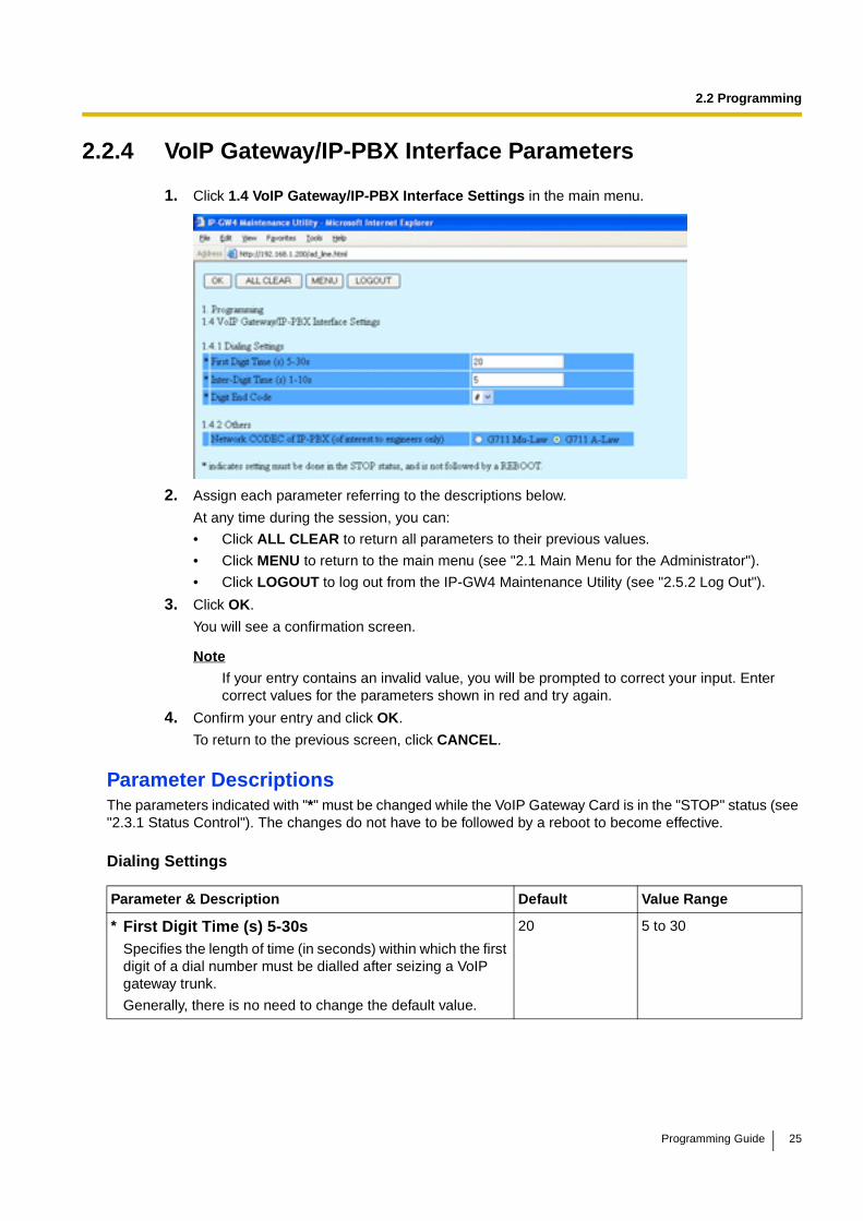
2.2 Programming
2.2.4 VoIP Gateway/IP-PBX Interface Parameters
1. Click 1.4 VoIP Gateway/IP-PBX Interface Settings in the main menu.
2. Assign each parameter referring to the descriptions below.
At any time during the session, you can:
• Click ALL CLEAR to return all parameters to their previous values.
• Click MENU to return to the main menu (see "2.1 Main Menu for the Administrator").
• Click LOGOUT to log out from the IP-GW4 Maintenance Utility (see "2.5.2 Log Out").
3. Click OK.
You will see a confirmation screen.
Note
If your entry contains an invalid value, you will be prompted to correct your input. Enter correct values for the parameters shown in red and try again.
4. Confirm your entry and click OK.
To return to the previous screen, click CANCEL.
Parameter DescriptionsThe parameters indicated with "*" must be changed while the VoIP Gateway Card is in the "STOP" status (see "2.3.1 Status Control"). The changes do not have to be followed by a reboot to become effective.
Dialing Settings
Parameter & Description Default Value Range
* First Digit Time (s) 5-30sSpecifies the length of time (in seconds) within which the first digit of a dial number must be dialled after seizing a VoIP gateway trunk.
Generally, there is no need to change the default value.
20 5 to 30
Programming Guide 25
2.2 Programming
Others
* Inter-Digit Time (s) 1-10sSpecifies the length of time (in seconds) within which subsequent digits of a dial number must be dialled.
Generally, there is no need to change the default value.
5 1 to 10
* Digit End CodeSpecifies the delimiter code to be used to signal the end of a dial number.
Generally, there is no need to change the default value.
# 0 to 9, #, *
Parameter & Description Default Value Range
Network CODEC of IP-PBXThe value of this parameter is set automatically as appropriate to the setting of the PBX.
There is no need to change the value.
Not applicable G.711 Mu-Law,G.711 A-Law
Parameter & Description Default Value Range
26 Programming Guide

2.2 Programming
2.2.5 Hunt Pattern Parameters
1. Click 1.5 Hunt Pattern (for Incoming Calls) in the main menu.
2. Assign each parameter referring to the descriptions below.
At any time during the session, you can:
• Click ALL CLEAR to return all parameters to their previous values.
• Click MENU to return to the main menu (see "2.1 Main Menu for the Administrator").
• Sort the hunt patterns in the table at the bottom of the screen:
a. Click the desired sort key and sort order from the Sort Option lists.
b. Click SORT.
• Delete the desired hunt pattern from the table at the bottom of the screen:
a. Select the appropriate check box for the hunt pattern you want to delete.
b. Click DELETE.
• Click LOGOUT to log out from the IP-GW4 Maintenance Utility (see "2.5.2 Log Out").
3. Click ENTRY.
A maximum of 16 hunt patterns can be created.
4. Click OK.
You will see a confirmation screen.
Note
If your entry contains an invalid value, you will be prompted to correct your input. Enter correct values for the parameters shown in red and try again.
5. Confirm your entry and click OK.
To return to the previous screen, click CANCEL.
Programming Guide 27
2.2 Programming
Parameter DescriptionsThe parameters indicated with "*" must be changed while the VoIP Gateway Card is in the "STOP" status (see "2.3.1 Status Control"). The changes do not have to be followed by a reboot to become effective.
Hunt GroupThe parameters below are used to assign VoIP gateway ports 1 and 2 to the hunt groups.
For details, refer to "Detailed Explanations".
Hunt Pattern EntryThe parameters below are used to create hunt patterns.
For details, refer to "Detailed Explanations".
Parameter Default Value Range
* Port1 Hunt group 1 Hunt group 1,Hunt group 2
* Port2 Hunt group 1 Hunt group 1,Hunt group 2
Parameter & Description Default Value Range
* Hunt Pattern No.Specifies the number for the hunt pattern to be created.
When changing the current settings of an existing hunt pattern, first delete the hunt pattern and then re-create with new values.
No default 1 to 16
* Receive Leading NumberSpecifies the leading digits in received numbers by which to determine the hunt group to direct incoming calls.
For example, to direct incoming calls with numbers starting with "9", specify the number "9" in this parameter. Likewise, to direct incoming calls with numbers starting with "1", specify the number "1".
However, if you want to direct incoming calls with numbers starting with "950" and "951" to separate hunt groups, it is necessary to make 2 hunt patterns with respective numbers, "950" and "951".
No default Max. 30 digits
* Hunt Group (Priority1)Specifies the hunt group to which incoming calls are directed first.
1 1, 2
* Hunt Group (Priority2)Specifies the hunt group to which incoming calls are directed when the VoIP gateway port assigned to Hunt Group (Priority1) is busy.
- 1, 2, - (disable)
28 Programming Guide
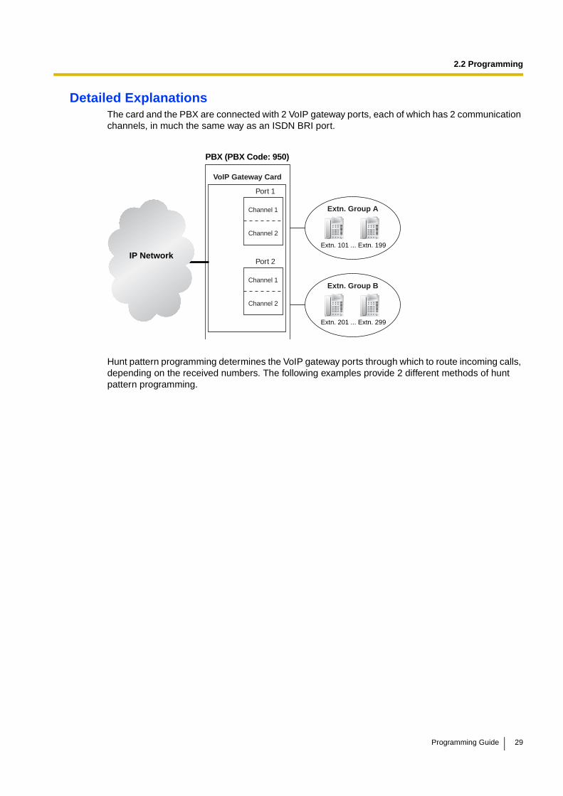
2.2 Programming
Detailed ExplanationsThe card and the PBX are connected with 2 VoIP gateway ports, each of which has 2 communication channels, in much the same way as an ISDN BRI port.
Hunt pattern programming determines the VoIP gateway ports through which to route incoming calls, depending on the received numbers. The following examples provide 2 different methods of hunt pattern programming.
IP Network
VoIP Gateway Card
Port 1
PBX (PBX Code: 950)
Extn. Group A
Extn. 101 ... Extn. 199
Channel 1
Channel 2
Extn. Group B
Extn. 201 ... Extn. 299
Port 2
Channel 1
Channel 2
Programming Guide 29

2.2 Programming
Example 1The following configuration is used to allocate 2 VoIP gateway ports (4 channels) to route incoming calls to both extension groups A and B.
When there are 4 incoming calls to extension group A in this configuration, no call can be routed to extension group B.
Hunt Group
Hunt Pattern Entry
Port1 Port2
Hunt Group Hunt group 1 Hunt group 1
Hunt Pattern No. 1
Receive Leading Number 9
Hunt Group (Priority1) 1
Hunt Group (Priority2) -
IP Network
VoIP Gateway Card
Port 1
PBX (PBX Code: 950)
Extn. Group A
Extn. 101 ... Extn. 199
Channel 1
Channel 2
Extn. Group B
Extn. 201 ... Extn. 299
Port 2Channel 1
Channel 2
Dials "950-101".
Dials "950-102".
Dials "950-103".
Dials "950-104".
Dials "950-201".
30 Programming Guide

2.2 Programming
Example 2The following configuration is used to allocate a single VoIP gateway port (2 channels) to individual extension groups. Specifically, with this configuration, calls to extension group A are routed through the port 1, and calls to extension group B are routed through the port 2.
This configuration rejects the third call to extension group A, while reserving the other port (the other 2 channels) through which to route calls to extension group B.
Hunt Group
Hunt Pattern Entry—1
Hunt Pattern Entry—2
It is possible to programme the PBX to allocate a single VoIP gateway port to individual extension groups A and B for making outgoing calls. With this programming, each extension group A and B can have a port for its exclusive use.
• The VoIP gateway port the extension group A uses to make outgoing calls: port 1
• The VoIP gateway port the extension group B uses to make outgoing calls: port 2
Port1 Port2
Hunt Group Hunt group 1 Hunt group 2
Hunt Pattern No. 1
Receive Leading Number 9501
Hunt Group (Priority1) 1
Hunt Group (Priority2) -
Hunt Pattern No. 2
Receive Leading Number 9502
Hunt Group (Priority1) 2
Hunt Group (Priority2) -
IP Network
VoIP Gateway Card
Port 1
PBX (PBX Code: 950)
Extn. Group A
Extn. 101 ... Extn. 199
Channel 1
Channel 2
Extn. Group B
Extn. 201 ... Extn. 299
Port 2Channel 1
Channel 2
Dials "950-101".
Dials "950-102".
Dials "950-103".
Dials "950-201".
Dials "950-202".
Programming Guide 31
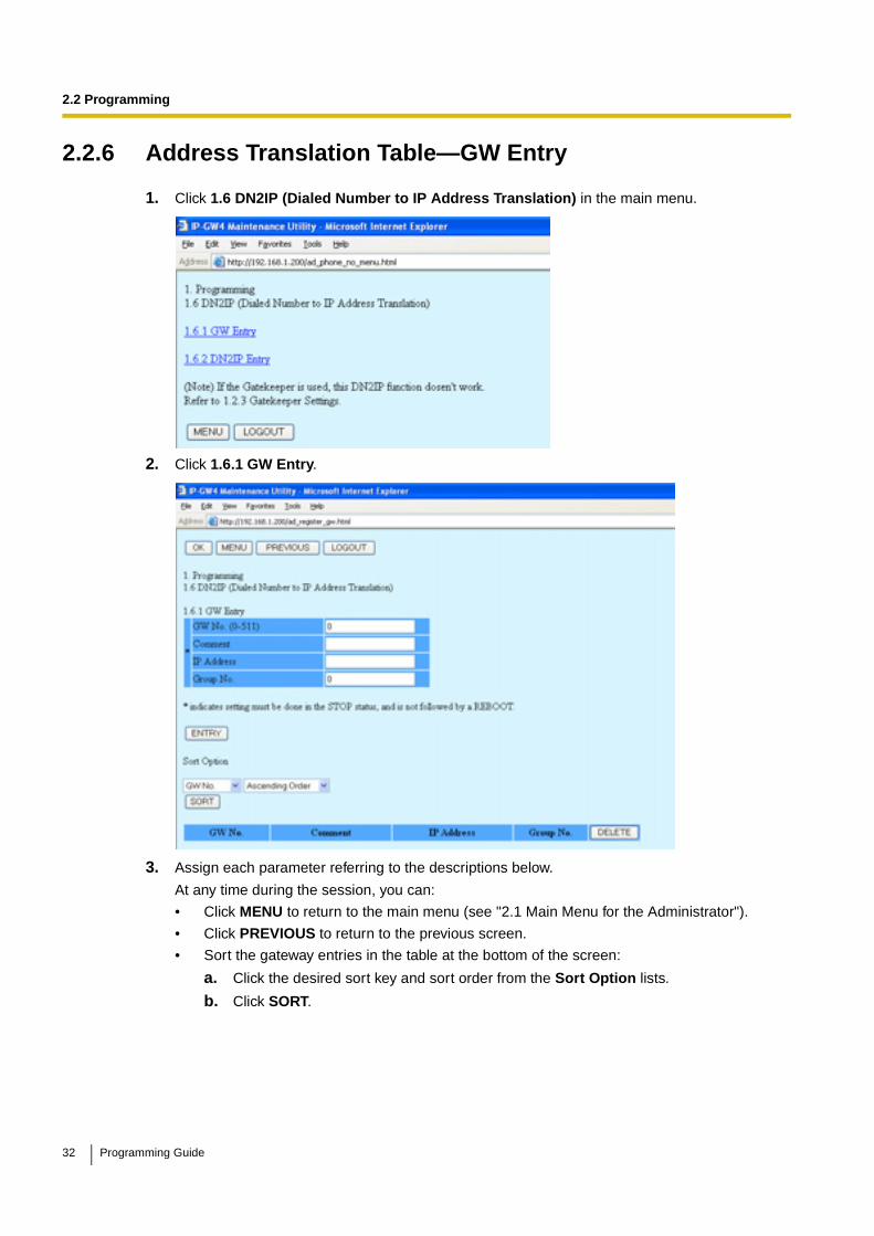
2.2 Programming
2.2.6 Address Translation Table—GW Entry
1. Click 1.6 DN2IP (Dialed Number to IP Address Translation) in the main menu.
2. Click 1.6.1 GW Entry.
3. Assign each parameter referring to the descriptions below.
At any time during the session, you can:
• Click MENU to return to the main menu (see "2.1 Main Menu for the Administrator").
• Click PREVIOUS to return to the previous screen.
• Sort the gateway entries in the table at the bottom of the screen:
a. Click the desired sort key and sort order from the Sort Option lists.
b. Click SORT.
32 Programming Guide

2.2 Programming
• Delete the desired gateway entry from the table at the bottom of the screen:
a. Select the appropriate check box for the gateway entry you want to delete.
NoteIf the gateway entry is registered to a DN2IP entry (see "2.2.7 Address Translation Table—DN2IP Entry"), no check box will be shown for the gateway entry.
b. Click DELETE.
• Click LOGOUT to log out from the IP-GW4 Maintenance Utility (see "2.5.2 Log Out").
4. Click ENTRY.
A maximum of 512 gateway entries can be created.
5. Click OK.
You will see a confirmation screen.
Note
If your entry contains an invalid value, you will be prompted to correct your input. Enter correct values for the parameters shown in red and try again.
6. Confirm your entry and click OK.
To return to the previous screen, click CANCEL.
Parameter DescriptionsThe parameters indicated with "*" must be changed while the VoIP Gateway Card is in the "STOP" status (see "2.3.1 Status Control"). The changes do not have to be followed by a reboot to become effective.
GW Entry
The parameters below are used to create gateway entries for both local and remote cards on the network, as a preliminary step to programming the address translation table (DN2IP).
For a programming example, refer to "4.2.5 Programming the Address Translation Table" of the VoIP Gateway Card Getting Started.
NoteIf you are using a gatekeeper, create the gateway entry only for the local card.
Parameter & Description Default Value Range
* GW No.Specifies the number for the gateway entry to be created.
When changing the current settings of an existing gateway entry, first delete the gateway entry and then re-create with new values.
0 0 to 511
* CommentSpecifies the comment for the gateway entry.
No default Max. 16 characters
* IP AddressSpecifies the IP address of the card.
No default The following addresses are invalid:
• Class D addresses
• Class E addresses
• Loopback addresses
Programming Guide 33
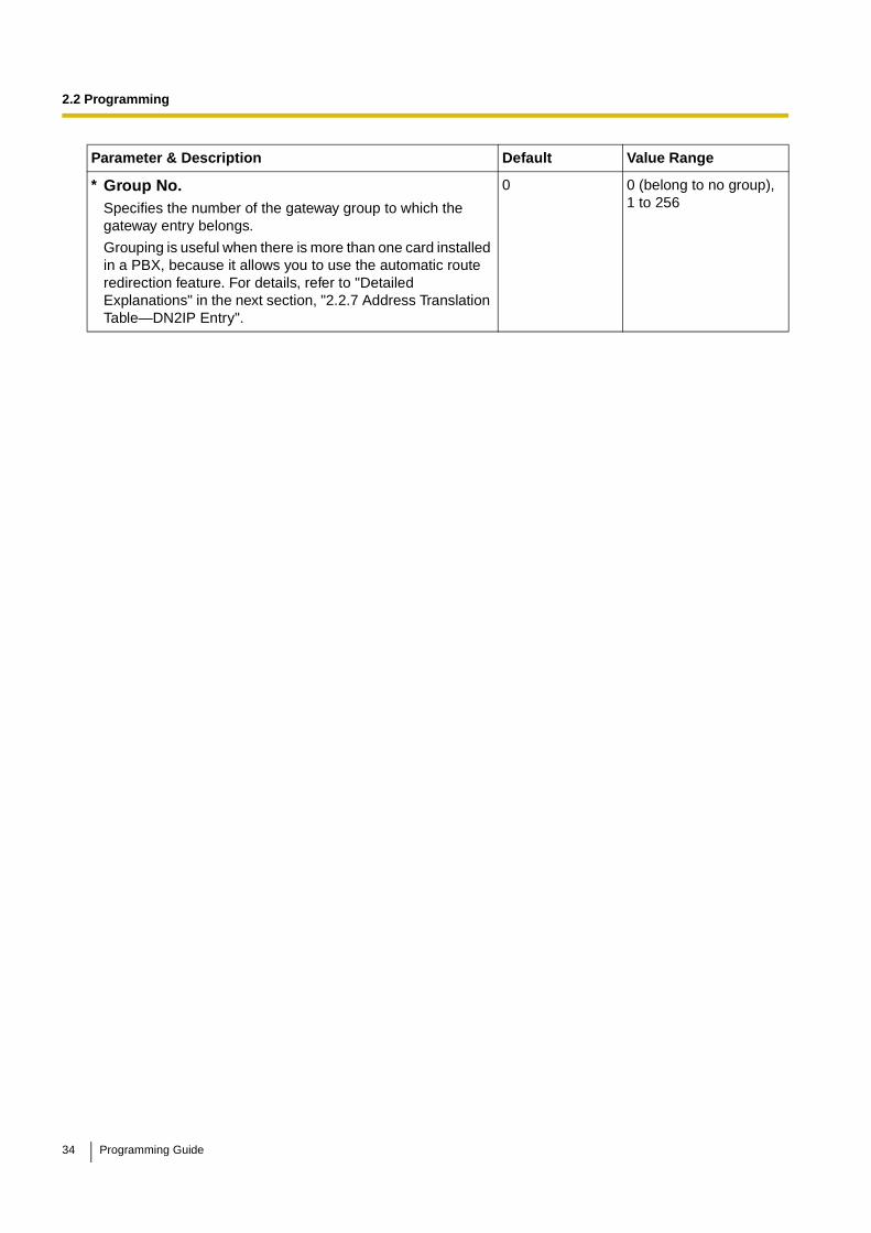
2.2 Programming
* Group No.Specifies the number of the gateway group to which the gateway entry belongs.
Grouping is useful when there is more than one card installed in a PBX, because it allows you to use the automatic route redirection feature. For details, refer to "Detailed Explanations" in the next section, "2.2.7 Address Translation Table—DN2IP Entry".
0 0 (belong to no group),1 to 256
Parameter & Description Default Value Range
34 Programming Guide
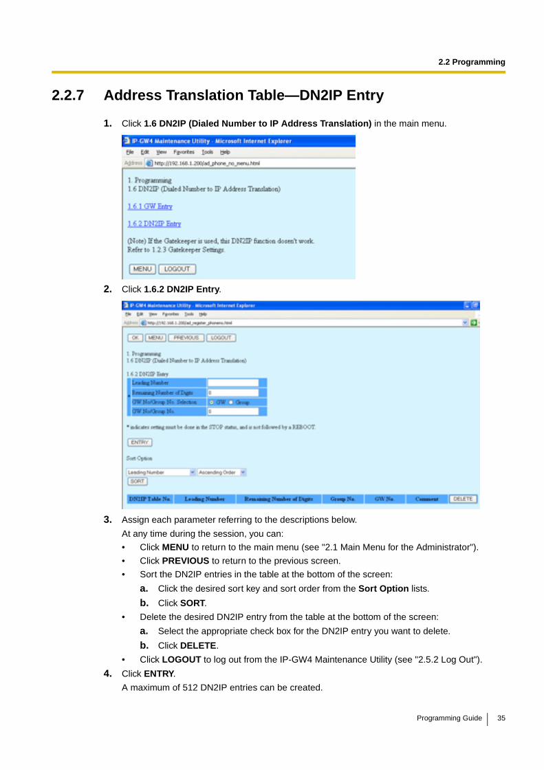
2.2 Programming
2.2.7 Address Translation Table—DN2IP Entry
1. Click 1.6 DN2IP (Dialed Number to IP Address Translation) in the main menu.
2. Click 1.6.2 DN2IP Entry.
3. Assign each parameter referring to the descriptions below.
At any time during the session, you can:
• Click MENU to return to the main menu (see "2.1 Main Menu for the Administrator").
• Click PREVIOUS to return to the previous screen.
• Sort the DN2IP entries in the table at the bottom of the screen:
a. Click the desired sort key and sort order from the Sort Option lists.
b. Click SORT.
• Delete the desired DN2IP entry from the table at the bottom of the screen:
a. Select the appropriate check box for the DN2IP entry you want to delete.
b. Click DELETE.
• Click LOGOUT to log out from the IP-GW4 Maintenance Utility (see "2.5.2 Log Out").
4. Click ENTRY.
A maximum of 512 DN2IP entries can be created.
Programming Guide 35
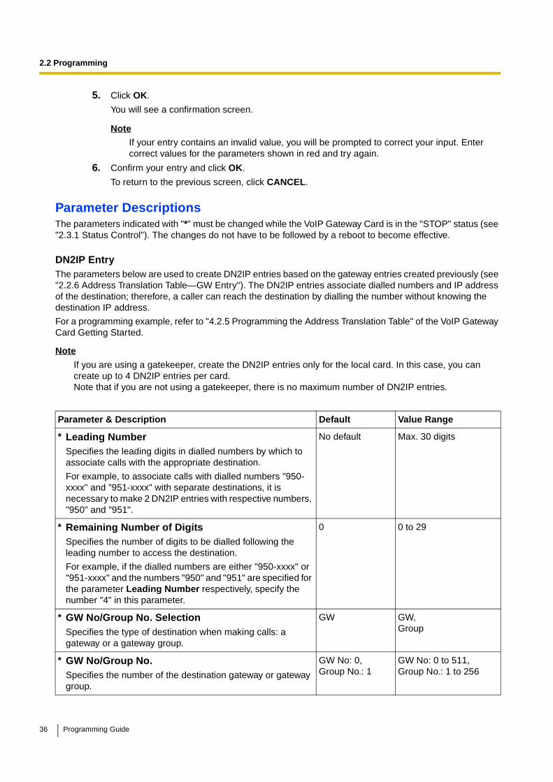
2.2 Programming
5. Click OK.
You will see a confirmation screen.
NoteIf your entry contains an invalid value, you will be prompted to correct your input. Enter correct values for the parameters shown in red and try again.
6. Confirm your entry and click OK.
To return to the previous screen, click CANCEL.
Parameter DescriptionsThe parameters indicated with "*" must be changed while the VoIP Gateway Card is in the "STOP" status (see "2.3.1 Status Control"). The changes do not have to be followed by a reboot to become effective.
DN2IP EntryThe parameters below are used to create DN2IP entries based on the gateway entries created previously (see "2.2.6 Address Translation Table—GW Entry"). The DN2IP entries associate dialled numbers and IP address of the destination; therefore, a caller can reach the destination by dialling the number without knowing the destination IP address.
For a programming example, refer to "4.2.5 Programming the Address Translation Table" of the VoIP Gateway Card Getting Started.
Note
If you are using a gatekeeper, create the DN2IP entries only for the local card. In this case, you can create up to 4 DN2IP entries per card.Note that if you are not using a gatekeeper, there is no maximum number of DN2IP entries.
Parameter & Description Default Value Range
* Leading NumberSpecifies the leading digits in dialled numbers by which to associate calls with the appropriate destination.
For example, to associate calls with dialled numbers "950-xxxx" and "951-xxxx" with separate destinations, it is necessary to make 2 DN2IP entries with respective numbers, "950" and "951".
No default Max. 30 digits
* Remaining Number of DigitsSpecifies the number of digits to be dialled following the leading number to access the destination.
For example, if the dialled numbers are either "950-xxxx" or "951-xxxx" and the numbers "950" and "951" are specified for the parameter Leading Number respectively, specify the number "4" in this parameter.
0 0 to 29
* GW No/Group No. SelectionSpecifies the type of destination when making calls: a gateway or a gateway group.
GW GW,Group
* GW No/Group No.Specifies the number of the destination gateway or gateway group.
GW No: 0,Group No.: 1
GW No: 0 to 511,Group No.: 1 to 256
36 Programming Guide
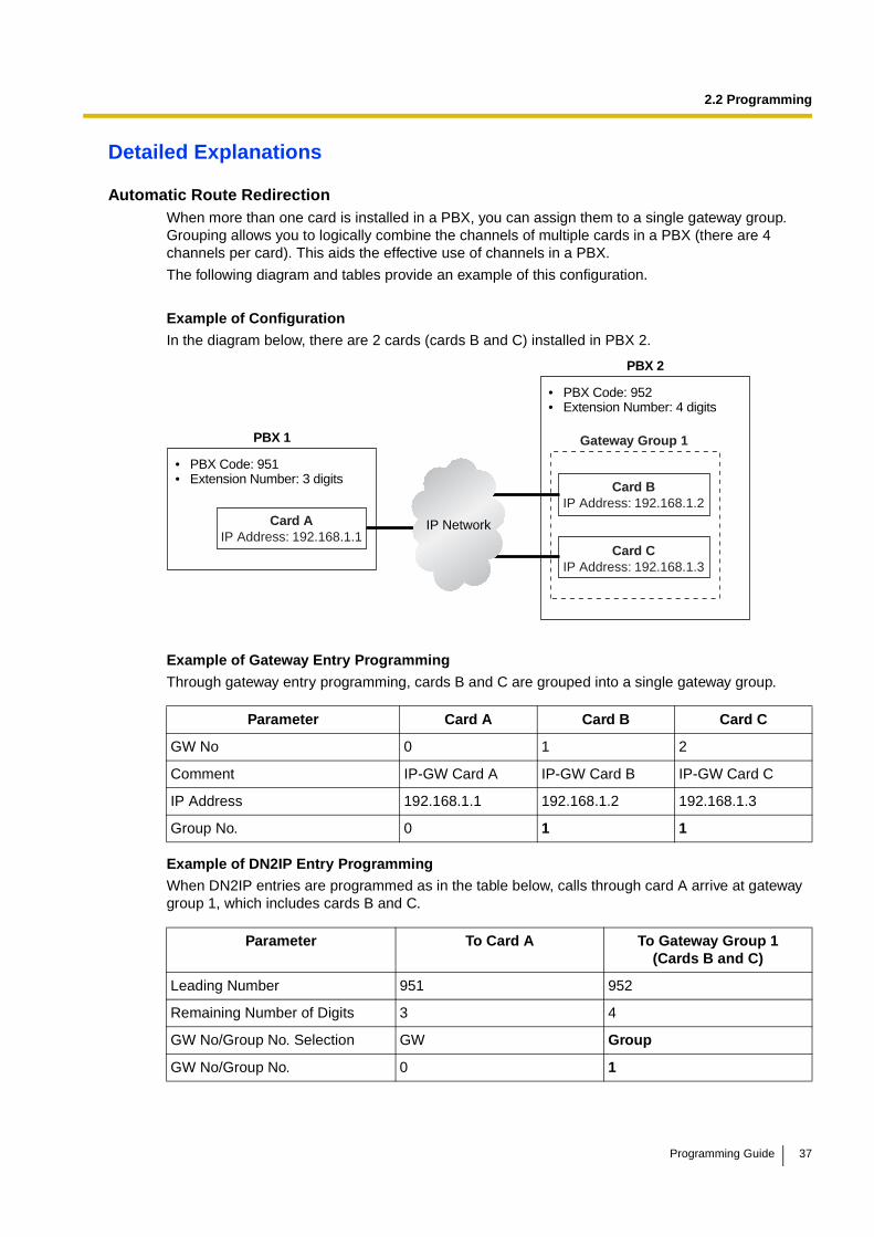
2.2 Programming
Detailed Explanations
Automatic Route RedirectionWhen more than one card is installed in a PBX, you can assign them to a single gateway group. Grouping allows you to logically combine the channels of multiple cards in a PBX (there are 4 channels per card). This aids the effective use of channels in a PBX.
The following diagram and tables provide an example of this configuration.
Example of Configuration
In the diagram below, there are 2 cards (cards B and C) installed in PBX 2.
Example of Gateway Entry Programming
Through gateway entry programming, cards B and C are grouped into a single gateway group.
Example of DN2IP Entry ProgrammingWhen DN2IP entries are programmed as in the table below, calls through card A arrive at gateway group 1, which includes cards B and C.
Parameter Card A Card B Card C
GW No 0 1 2
Comment IP-GW Card A IP-GW Card B IP-GW Card C
IP Address 192.168.1.1 192.168.1.2 192.168.1.3
Group No. 0 1 1
Parameter To Card A To Gateway Group 1(Cards B and C)
Leading Number 951 952
Remaining Number of Digits 3 4
GW No/Group No. Selection GW Group
GW No/Group No. 0 1
Card AIP Address: 192.168.1.1
PBX 1
• PBX Code: 951• Extension Number: 3 digits
PBX 2
• PBX Code: 952• Extension Number: 4 digits
Card BIP Address: 192.168.1.2
Card CIP Address: 192.168.1.3
Gateway Group 1
IP Network
Programming Guide 37

2.2 Programming
The automatic route redirection feature activates in this configuration. If a call is made through card A to gateway group 1 when all 4 channels of card B are busy, card A automatically redirects the call to card C.
This is possible because by grouping, PBX 1 sees PBX 2 as having a combined set of 8 channels, not 2 separate sets of 4 channels.
Note
The automatic route redirection feature cannot be used in a network where a gatekeeper is used. For details about gatekeeper settings, refer to "Gatekeeper Settings" in "2.2.2 H.323 Parameters".
38 Programming Guide
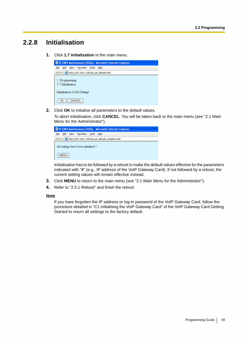
2.2 Programming
2.2.8 Initialisation
1. Click 1.7 Initialization in the main menu.
2. Click OK to initialise all parameters to the default values.
To abort initialisation, click CANCEL. You will be taken back to the main menu (see "2.1 Main Menu for the Administrator").
Initialisation has to be followed by a reboot to make the default values effective for the parameters indicated with "#" (e.g., IP address of the VoIP Gateway Card). If not followed by a reboot, the current setting values will remain effective instead.
3. Click MENU to return to the main menu (see "2.1 Main Menu for the Administrator").
4. Refer to "2.5.1 Reboot" and finish the reboot.
Note
If you have forgotten the IP address or log-in password of the VoIP Gateway Card, follow the procedure detailed in "C1 Initialising the VoIP Gateway Card" of the VoIP Gateway Card Getting Started to return all settings to the factory default.
Programming Guide 39
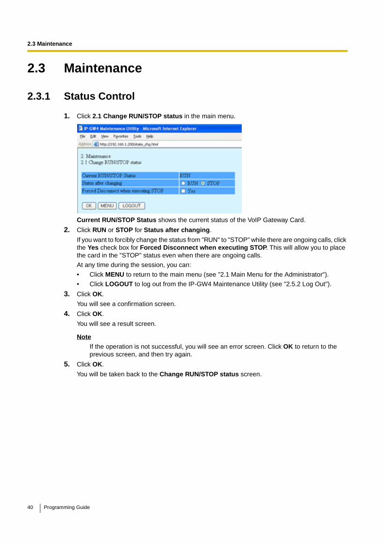
2.3 Maintenance
2.3 Maintenance
2.3.1 Status Control
1. Click 2.1 Change RUN/STOP status in the main menu.
Current RUN/STOP Status shows the current status of the VoIP Gateway Card.
2. Click RUN or STOP for Status after changing.
If you want to forcibly change the status from "RUN" to "STOP" while there are ongoing calls, click the Yes check box for Forced Disconnect when executing STOP. This will allow you to place the card in the "STOP" status even when there are ongoing calls.
At any time during the session, you can:
• Click MENU to return to the main menu (see "2.1 Main Menu for the Administrator").
• Click LOGOUT to log out from the IP-GW4 Maintenance Utility (see "2.5.2 Log Out").
3. Click OK.
You will see a confirmation screen.
4. Click OK.
You will see a result screen.
Note
If the operation is not successful, you will see an error screen. Click OK to return to the previous screen, and then try again.
5. Click OK.
You will be taken back to the Change RUN/STOP status screen.
40 Programming Guide
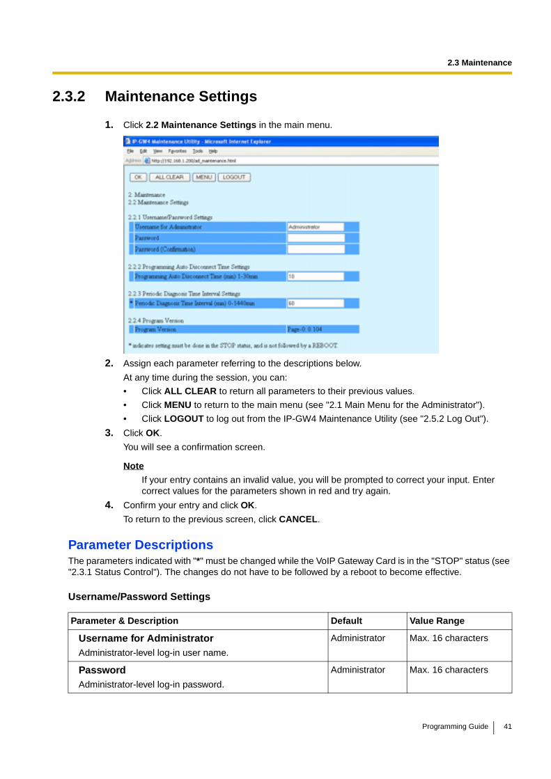
2.3 Maintenance
2.3.2 Maintenance Settings
1. Click 2.2 Maintenance Settings in the main menu.
2. Assign each parameter referring to the descriptions below.
At any time during the session, you can:
• Click ALL CLEAR to return all parameters to their previous values.
• Click MENU to return to the main menu (see "2.1 Main Menu for the Administrator").
• Click LOGOUT to log out from the IP-GW4 Maintenance Utility (see "2.5.2 Log Out").
3. Click OK.
You will see a confirmation screen.
Note
If your entry contains an invalid value, you will be prompted to correct your input. Enter correct values for the parameters shown in red and try again.
4. Confirm your entry and click OK.
To return to the previous screen, click CANCEL.
Parameter DescriptionsThe parameters indicated with "*" must be changed while the VoIP Gateway Card is in the "STOP" status (see "2.3.1 Status Control"). The changes do not have to be followed by a reboot to become effective.
Username/Password Settings
Parameter & Description Default Value Range
Username for AdministratorAdministrator-level log-in user name.
Administrator Max. 16 characters
PasswordAdministrator-level log-in password.
Administrator Max. 16 characters
Programming Guide 41
2.3 Maintenance
Programming Auto Disconnect Time Settings
Periodic Diagnosis Time Interval Settings
Program Version
Password (Confirmation)Confirmation of the administrator-level log-in password.
No default Max. 16 characters
Parameter & Description Default Value Range
Programming Auto Disconnect Time (min) 1-30minSpecifies the time (in minutes) until programming is automatically terminated.
If the specified period of time passes with no programming input, programming will automatically be terminated. This prevents problems caused by continuation of log-in status in cases such as being unable to log out due to the sudden failure of a PC.
10 1 to 30
Parameter & Description Default Value Range
* Periodic Diagnosis Time Interval (min) 0-1440minSpecifies the time (in minutes) between periodic self-diagnoses to test operation as described in "2.3.3 Diagnosis".
If failures are detected during the self-diagnosis, the card will alert the PBX.
60 0 (no periodic diagnosis),1 to 1440
Parameter Default Value Range
Program Version Display only
Parameter & Description Default Value Range
42 Programming Guide
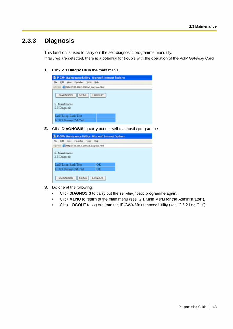
2.3 Maintenance
2.3.3 Diagnosis
This function is used to carry out the self-diagnostic programme manually.
If failures are detected, there is a potential for trouble with the operation of the VoIP Gateway Card.
1. Click 2.3 Diagnosis in the main menu.
2. Click DIAGNOSIS to carry out the self-diagnostic programme.
3. Do one of the following:
• Click DIAGNOSIS to carry out the self-diagnostic programme again.
• Click MENU to return to the main menu (see "2.1 Main Menu for the Administrator").
• Click LOGOUT to log out from the IP-GW4 Maintenance Utility (see "2.5.2 Log Out").
Programming Guide 43
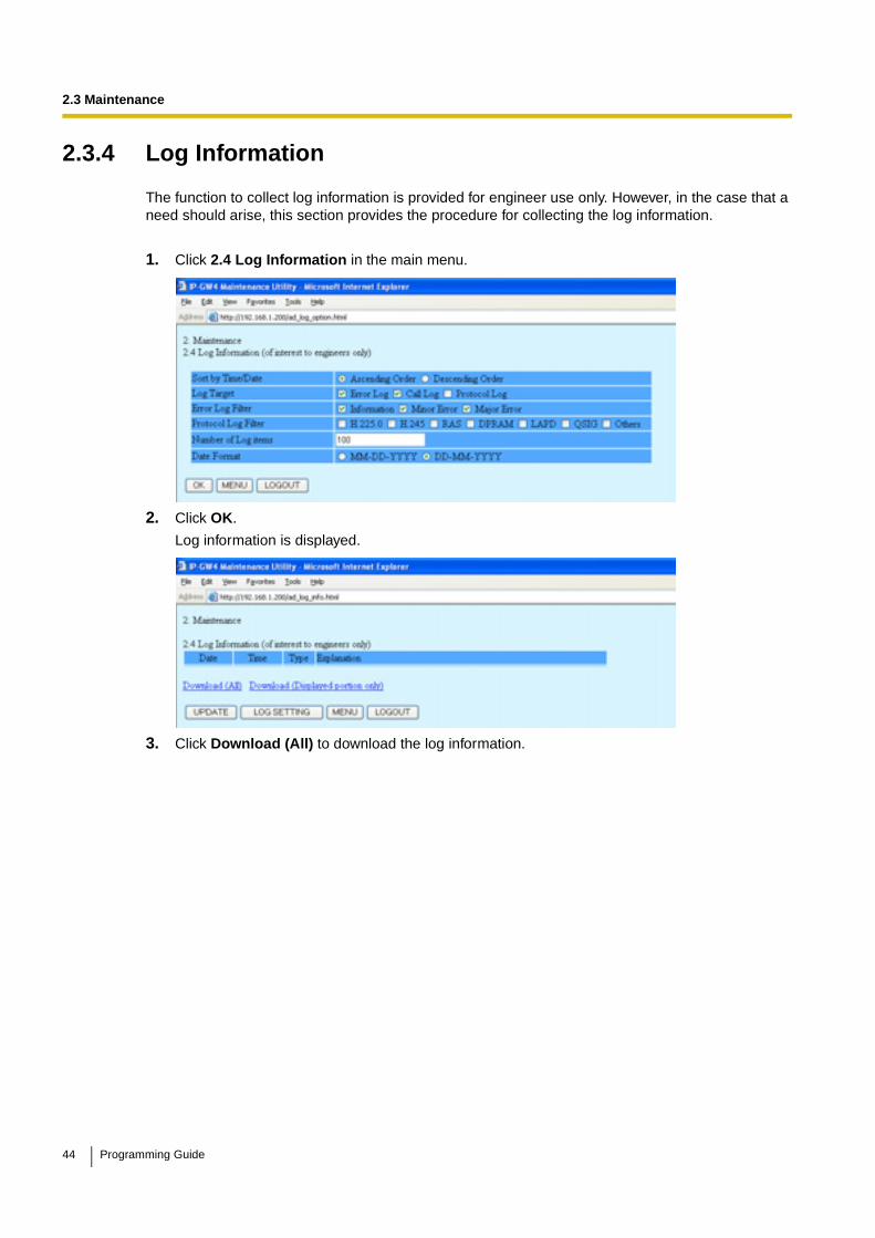
2.3 Maintenance
2.3.4 Log Information
The function to collect log information is provided for engineer use only. However, in the case that a need should arise, this section provides the procedure for collecting the log information.
1. Click 2.4 Log Information in the main menu.
2. Click OK.
Log information is displayed.
3. Click Download (All) to download the log information.
44 Programming Guide
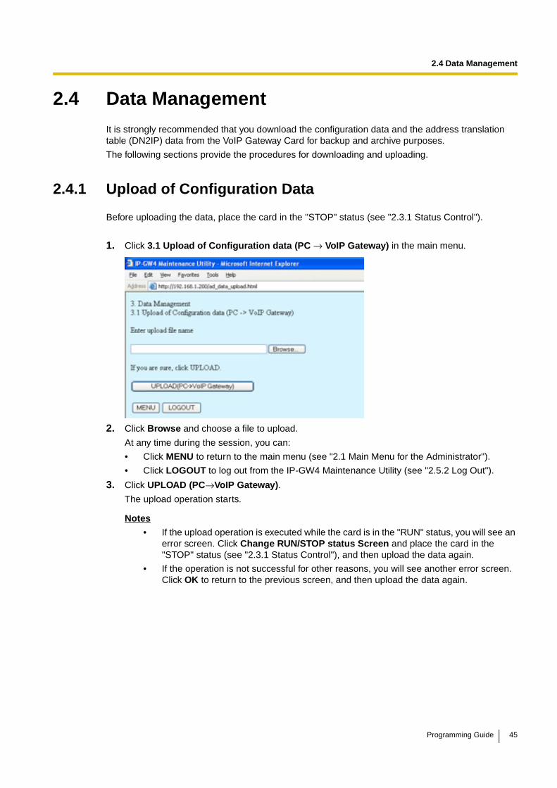
2.4 Data Management
2.4 Data ManagementIt is strongly recommended that you download the configuration data and the address translation table (DN2IP) data from the VoIP Gateway Card for backup and archive purposes.
The following sections provide the procedures for downloading and uploading.
2.4.1 Upload of Configuration Data
Before uploading the data, place the card in the "STOP" status (see "2.3.1 Status Control").
1. Click 3.1 Upload of Configuration data (PC → VoIP Gateway) in the main menu.
2. Click Browse and choose a file to upload.
At any time during the session, you can:
• Click MENU to return to the main menu (see "2.1 Main Menu for the Administrator").
• Click LOGOUT to log out from the IP-GW4 Maintenance Utility (see "2.5.2 Log Out").
3. Click UPLOAD (PC→VoIP Gateway).
The upload operation starts.
Notes
• If the upload operation is executed while the card is in the "RUN" status, you will see an error screen. Click Change RUN/STOP status Screen and place the card in the "STOP" status (see "2.3.1 Status Control"), and then upload the data again.
• If the operation is not successful for other reasons, you will see another error screen. Click OK to return to the previous screen, and then upload the data again.
Programming Guide 45
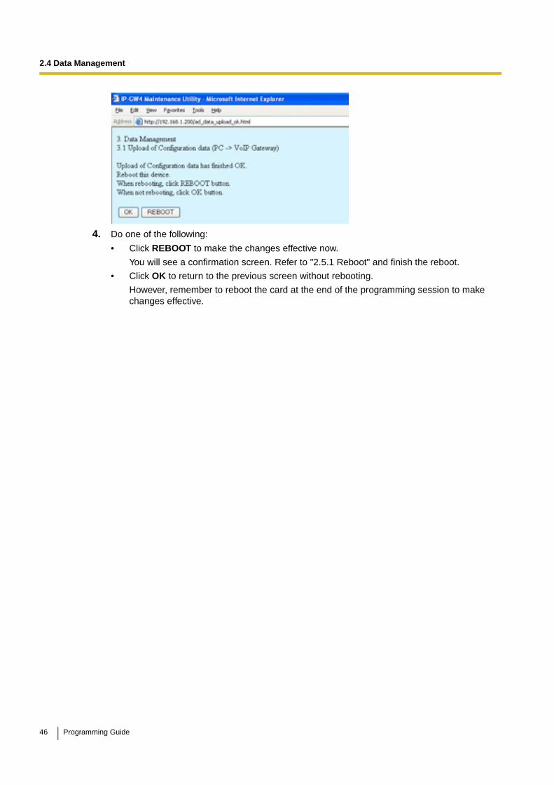
2.4 Data Management
4. Do one of the following:
• Click REBOOT to make the changes effective now.
You will see a confirmation screen. Refer to "2.5.1 Reboot" and finish the reboot.
• Click OK to return to the previous screen without rebooting.
However, remember to reboot the card at the end of the programming session to make changes effective.
46 Programming Guide
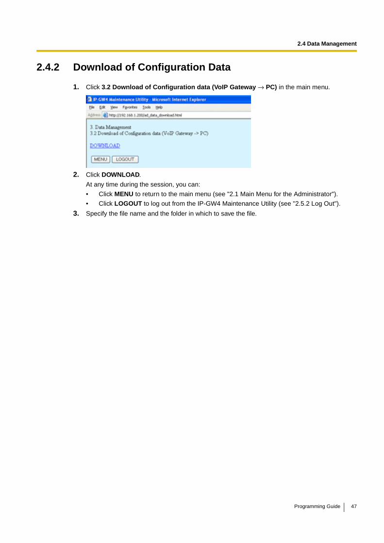
2.4 Data Management
2.4.2 Download of Configuration Data
1. Click 3.2 Download of Configuration data (VoIP Gateway → PC) in the main menu.
2. Click DOWNLOAD.
At any time during the session, you can:
• Click MENU to return to the main menu (see "2.1 Main Menu for the Administrator").
• Click LOGOUT to log out from the IP-GW4 Maintenance Utility (see "2.5.2 Log Out").
3. Specify the file name and the folder in which to save the file.
Programming Guide 47

2.4 Data Management
2.4.3 Upload of Address Translation Table
Before uploading the data, place the card in the "STOP" status (see "2.3.1 Status Control").
1. Click 3.3 Upload of DN2IP data (PC → VoIP Gateway) in the main menu.
2. Click Browse and choose a file to upload.
At any time during the session, you can:
• Click MENU to return to the main menu (see "2.1 Main Menu for the Administrator").
• Click LOGOUT to log out from the IP-GW4 Maintenance Utility (see "2.5.2 Log Out").
3. Click UPLOAD (PC→VoIP Gateway).
The upload operation starts.
Notes• If the upload operation is executed while the card is in the "RUN" status, you will see an
error screen. Click Change RUN/STOP status Screen and place the card in the "STOP" status (see "2.3.1 Status Control"), and then upload the data again.
• If the operation is not successful for other reasons, you will see another error screen. Click OK to return to the previous screen, and then upload the data again.
4. Do one of the following:
• Click REBOOT to make the changes effective now.
You will see a confirmation screen. Refer to "2.5.1 Reboot" and finish the reboot.
• Click OK to return to the previous screen without rebooting.
48 Programming Guide

2.4 Data Management
However, remember to reboot the card at the end of the programming session to make changes effective.
Programming Guide 49

2.4 Data Management
2.4.4 Download of Address Translation Table
1. Click 3.4 Download of DN2IP data (VoIP Gateway → PC) in the main menu.
2. Click DOWNLOAD.
At any time during the session, you can:
• Click MENU to return to the main menu (see "2.1 Main Menu for the Administrator").
• Click LOGOUT to log out from the IP-GW4 Maintenance Utility (see "2.5.2 Log Out").
3. Specify the file name and the folder in which to save the file.
50 Programming Guide
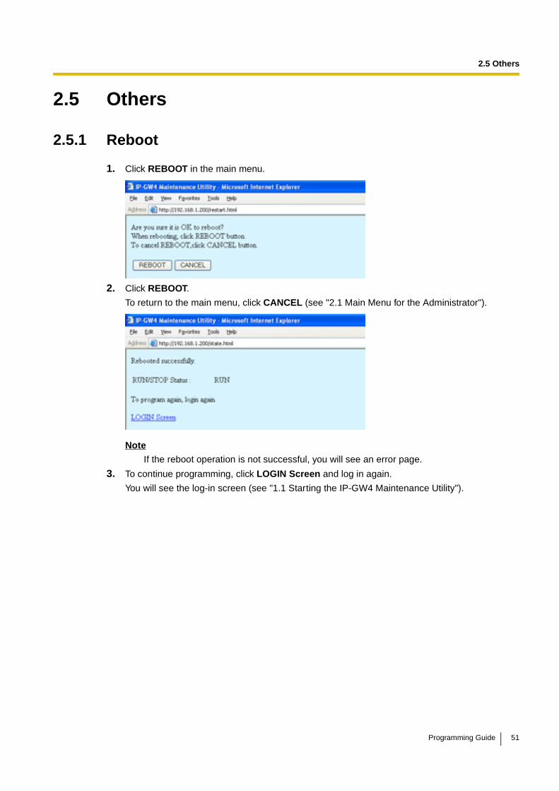
2.5 Others
2.5 Others
2.5.1 Reboot
1. Click REBOOT in the main menu.
2. Click REBOOT.
To return to the main menu, click CANCEL (see "2.1 Main Menu for the Administrator").
Note
If the reboot operation is not successful, you will see an error page.
3. To continue programming, click LOGIN Screen and log in again.
You will see the log-in screen (see "1.1 Starting the IP-GW4 Maintenance Utility").
Programming Guide 51
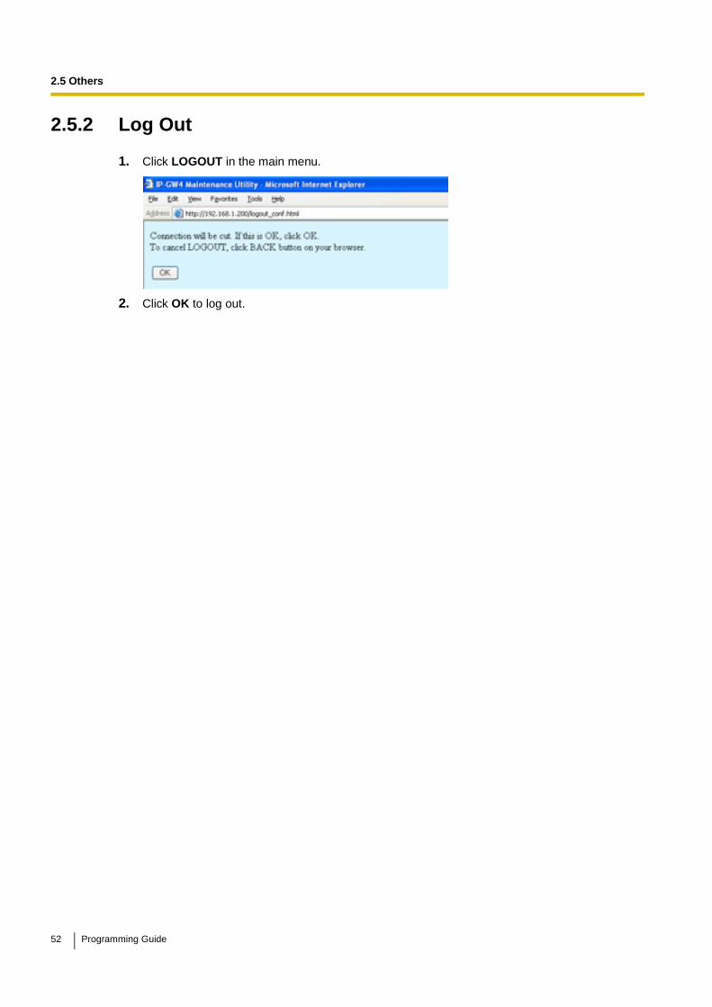
2.5 Others
2.5.2 Log Out
1. Click LOGOUT in the main menu.
2. Click OK to log out.
52 Programming Guide
Section 3
Installer Functions
This section provides operating instructions for the IP-GW4 Maintenance Utility when logged in as the Installer.
Programming Guide 53
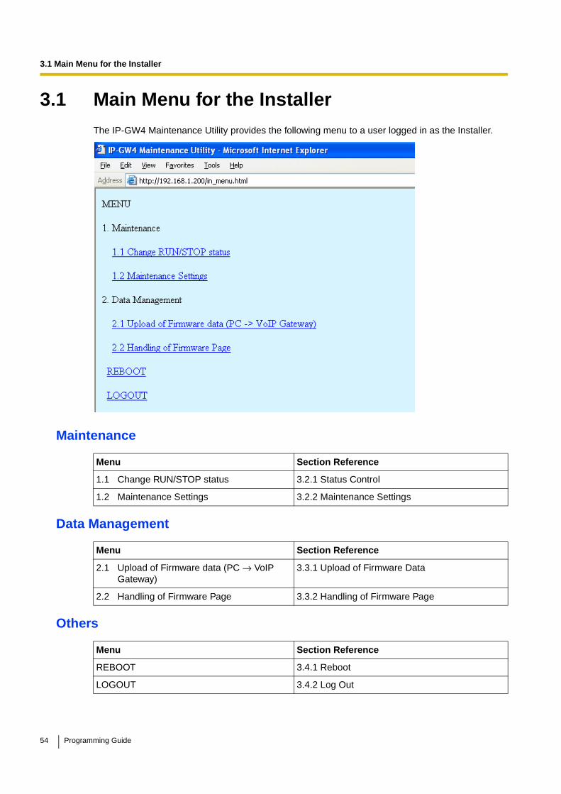
3.1 Main Menu for the Installer
3.1 Main Menu for the InstallerThe IP-GW4 Maintenance Utility provides the following menu to a user logged in as the Installer.
Maintenance
Data Management
Others
Menu Section Reference
1.1 Change RUN/STOP status 3.2.1 Status Control
1.2 Maintenance Settings 3.2.2 Maintenance Settings
Menu Section Reference
2.1 Upload of Firmware data (PC → VoIP Gateway)
3.3.1 Upload of Firmware Data
2.2 Handling of Firmware Page 3.3.2 Handling of Firmware Page
Menu Section Reference
REBOOT 3.4.1 Reboot
LOGOUT 3.4.2 Log Out
54 Programming Guide

3.2 Maintenance
3.2 Maintenance
3.2.1 Status Control
1. Click 1.1 Change RUN/STOP status in the main menu.
Current RUN/STOP Status shows the current status of the VoIP Gateway Card.
2. Click RUN or STOP for Status after changing.
If you want to forcibly change the status from "RUN" to "STOP" while there are ongoing calls, click the Yes check box for Forced Disconnect when executing STOP. This will allow you to place the card in the "STOP" status even when there are ongoing calls.
At any time during the session, you can:
• Click MENU to return to the main menu (see "3.1 Main Menu for the Installer").
• Click LOGOUT to log out from the IP-GW4 Maintenance Utility (see "3.4.2 Log Out").
3. Click OK.
You will see a confirmation screen.
4. Click OK.
You will see a result screen.
Note
If the operation is not successful, you will see an error screen. Click OK to return to the previous screen, and then try again.
5. Click OK.
You will be taken back to the Change RUN/STOP status screen.
Programming Guide 55

3.2 Maintenance
3.2.2 Maintenance Settings
1. Click 1.2 Maintenance Settings in the main menu.
2. Assign each parameter referring to the descriptions below.
At any time during the session, you can:
• Click ALL CLEAR to return all parameters to their previous values.
• Click MENU to return to the main menu (see "3.1 Main Menu for the Installer").
• Click LOGOUT to log out from the IP-GW4 Maintenance Utility (see "3.4.2 Log Out").
3. Click OK.
You will see a confirmation screen.
NoteIf your entry contains an invalid value, you will be prompted to correct your input. Enter correct values for the parameters shown in red and try again.
4. Confirm your entry and click OK.
To return to the previous screen, click CANCEL.
Parameter Descriptions
Username/Password Settings
Parameter & Description Default Value Range
Username for InstallerInstaller-level log-in user name.
Installer Max. 16 characters
PasswordInstaller-level log-in password.
Installer Max. 16 characters
Password (Confirmation)Confirmation of the installer-level log-in password.
No default Max. 16 characters
56 Programming Guide
3.2 Maintenance
Program Version
Parameter Default Value Range
Program Version Display only
Programming Guide 57
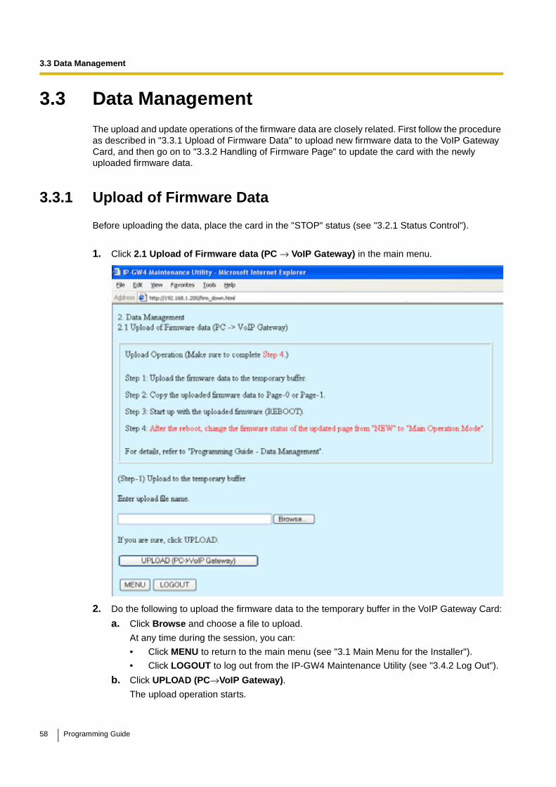
3.3 Data Management
3.3 Data ManagementThe upload and update operations of the firmware data are closely related. First follow the procedure as described in "3.3.1 Upload of Firmware Data" to upload new firmware data to the VoIP Gateway Card, and then go on to "3.3.2 Handling of Firmware Page" to update the card with the newly uploaded firmware data.
3.3.1 Upload of Firmware Data
Before uploading the data, place the card in the "STOP" status (see "3.2.1 Status Control").
1. Click 2.1 Upload of Firmware data (PC → VoIP Gateway) in the main menu.
2. Do the following to upload the firmware data to the temporary buffer in the VoIP Gateway Card:
a. Click Browse and choose a file to upload.
At any time during the session, you can:
• Click MENU to return to the main menu (see "3.1 Main Menu for the Installer").
• Click LOGOUT to log out from the IP-GW4 Maintenance Utility (see "3.4.2 Log Out").
b. Click UPLOAD (PC→VoIP Gateway).
The upload operation starts.
58 Programming Guide
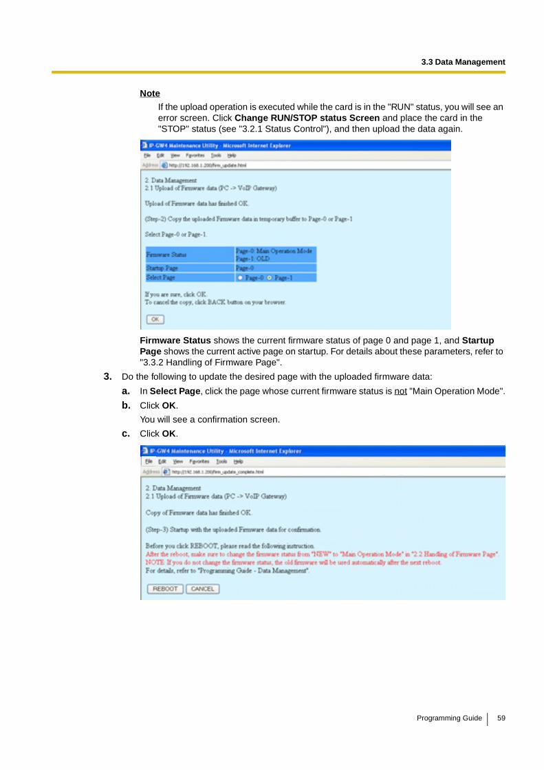
3.3 Data Management
NoteIf the upload operation is executed while the card is in the "RUN" status, you will see an error screen. Click Change RUN/STOP status Screen and place the card in the "STOP" status (see "3.2.1 Status Control"), and then upload the data again.
Firmware Status shows the current firmware status of page 0 and page 1, and Startup Page shows the current active page on startup. For details about these parameters, refer to "3.3.2 Handling of Firmware Page".
3. Do the following to update the desired page with the uploaded firmware data:
a. In Select Page, click the page whose current firmware status is not "Main Operation Mode".
b. Click OK.
You will see a confirmation screen.
c. Click OK.
Programming Guide 59
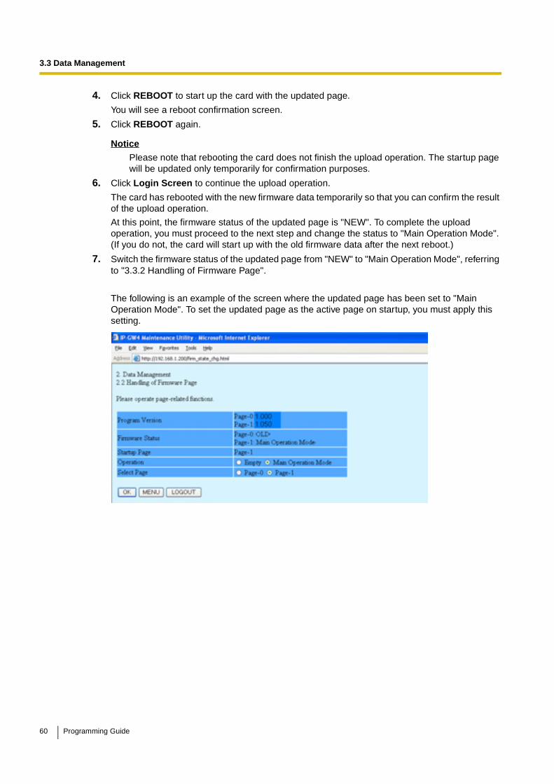
3.3 Data Management
4. Click REBOOT to start up the card with the updated page.
You will see a reboot confirmation screen.
5. Click REBOOT again.
NoticePlease note that rebooting the card does not finish the upload operation. The startup page will be updated only temporarily for confirmation purposes.
6. Click Login Screen to continue the upload operation.
The card has rebooted with the new firmware data temporarily so that you can confirm the result of the upload operation.
At this point, the firmware status of the updated page is "NEW". To complete the upload operation, you must proceed to the next step and change the status to "Main Operation Mode". (If you do not, the card will start up with the old firmware data after the next reboot.)
7. Switch the firmware status of the updated page from "NEW" to "Main Operation Mode", referring to "3.3.2 Handling of Firmware Page".
The following is an example of the screen where the updated page has been set to "Main Operation Mode". To set the updated page as the active page on startup, you must apply this setting.
60 Programming Guide
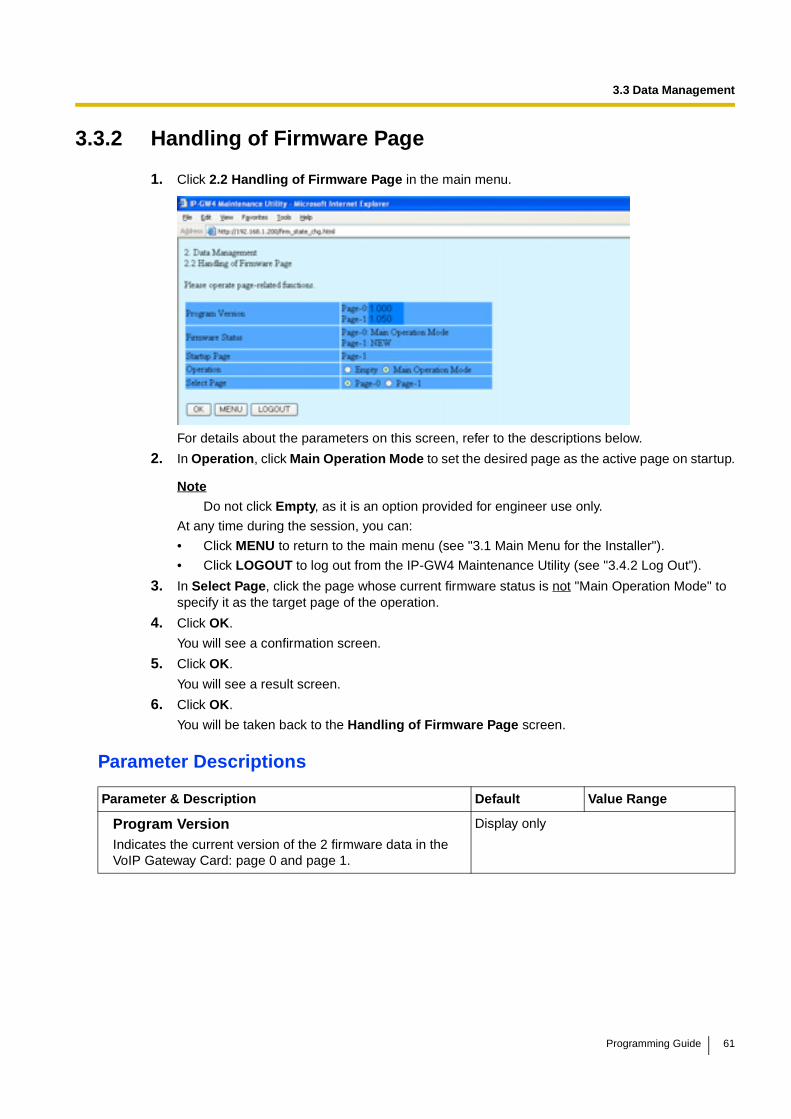
3.3 Data Management
3.3.2 Handling of Firmware Page
1. Click 2.2 Handling of Firmware Page in the main menu.
For details about the parameters on this screen, refer to the descriptions below.
2. In Operation, click Main Operation Mode to set the desired page as the active page on startup.
Note
Do not click Empty, as it is an option provided for engineer use only.
At any time during the session, you can:
• Click MENU to return to the main menu (see "3.1 Main Menu for the Installer").
• Click LOGOUT to log out from the IP-GW4 Maintenance Utility (see "3.4.2 Log Out").
3. In Select Page, click the page whose current firmware status is not "Main Operation Mode" to specify it as the target page of the operation.
4. Click OK.
You will see a confirmation screen.
5. Click OK.
You will see a result screen.
6. Click OK.
You will be taken back to the Handling of Firmware Page screen.
Parameter Descriptions
Parameter & Description Default Value Range
Program VersionIndicates the current version of the 2 firmware data in the VoIP Gateway Card: page 0 and page 1.
Display only
Programming Guide 61
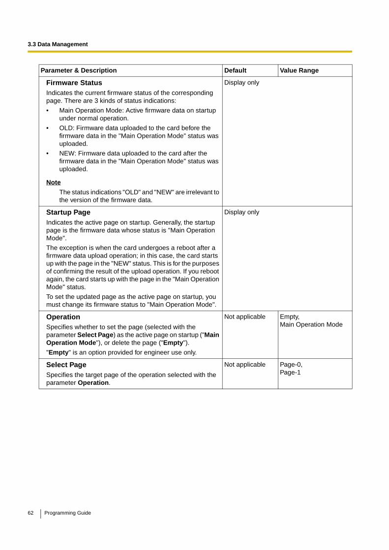
3.3 Data Management
Firmware StatusIndicates the current firmware status of the corresponding page. There are 3 kinds of status indications:
• Main Operation Mode: Active firmware data on startup under normal operation.
• OLD: Firmware data uploaded to the card before the firmware data in the "Main Operation Mode" status was uploaded.
• NEW: Firmware data uploaded to the card after the firmware data in the "Main Operation Mode" status was uploaded.
Note
The status indications "OLD" and "NEW" are irrelevant to the version of the firmware data.
Display only
Startup PageIndicates the active page on startup. Generally, the startup page is the firmware data whose status is "Main Operation Mode".
The exception is when the card undergoes a reboot after a firmware data upload operation; in this case, the card starts up with the page in the "NEW" status. This is for the purposes of confirming the result of the upload operation. If you reboot again, the card starts up with the page in the "Main Operation Mode" status.
To set the updated page as the active page on startup, you must change its firmware status to "Main Operation Mode".
Display only
OperationSpecifies whether to set the page (selected with the parameter Select Page) as the active page on startup ("Main Operation Mode"), or delete the page ("Empty").
"Empty" is an option provided for engineer use only.
Not applicable Empty,Main Operation Mode
Select PageSpecifies the target page of the operation selected with the parameter Operation.
Not applicable Page-0,Page-1
Parameter & Description Default Value Range
62 Programming Guide
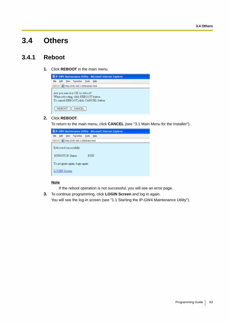
3.4 Others
3.4 Others
3.4.1 Reboot
1. Click REBOOT in the main menu.
2. Click REBOOT.
To return to the main menu, click CANCEL (see "3.1 Main Menu for the Installer").
Note
If the reboot operation is not successful, you will see an error page.
3. To continue programming, click LOGIN Screen and log in again.
You will see the log-in screen (see "1.1 Starting the IP-GW4 Maintenance Utility").
Programming Guide 63

3.4 Others
3.4.2 Log Out
1. Click LOGOUT in the main menu.
2. Click OK to log out.
64 Programming Guide

Programming Guide 65
Index
Index
AAutomatic Route Redirection 37
BBandwidth 22, 24
CCall Signaling Model 16Change RUN/STOP status 40, 55CODEC Frame Settings 20, 22
DDefault Gateway 11DHCP Settings 11Diagnosis 43Dialing Settings 25DiffServ 19Digit End Code 26DN2IP (Dialed Number to IP Address Translation) 32, 35DN2IP Entry 35, 36Download of Address Translation Table 50Download of Configuration Data 47DSCP 19, 22DTMF Detection 20, 23DTMF Detection Level 21DTMF Relay 20, 23
EEcho Canceller 20ECM (Error Correction Model) 23Empty 62
FFast Connect 17FAX High Reliable Method 21, 24FAX Signal Detection 20, 23Firmware Status 62First Digit Time 25
GG.168 20G.711A 15G.711Mu 15G.723.1 15G.723.1 Rate 20G.723.1 VAD (Voice Activity Detection) 20G.729A 15Gatekeeper Settings 16GW Entry 32, 33
HH.225 Port No. 15H.245 Port No. 15H.323 14H.323 Detailed Settings 14Handling of Firmware Page 61Host Name 12
HTTP Settings 12Hunt Pattern (for Incoming Calls) 27
IInitialisation 39Inter-Digit Time 26IP Address 11IP Address Settings 11IP Header 19, 21
JJitter buffer Settings 19
LLAN 22, 24LAN Disconnect Threshold Time 12Log Information 44Log Out 52, 64
MMain Menu for the Administrator 8Main Menu for the Installer 54Main Operation Mode 62Maintenance Settings 41, 56
NNetwork CODEC of IP-PBX 26Network Settings, General 10
PPacket Sending Interval 20, 22, 23, 24Periodic Diagnosis Time Interval Settings 42Port Number Settings 15PPP (Point-to-Point Protocol) 23, 24Program Version 42, 57, 61Programming Auto Disconnect Time Settings 42
QQoS Field Settings 19, 21QSIG Connectionless Tunneling Settings 12
RRAS Port No. 15Reboot 51, 63RTP/RTCP Port No. 15
SStartup Page 62Subnet Mask 11Super G3 Mode 24
TToS 19, 21
UUpload of Address Translation Table 48
66 Programming Guide

Index
Upload of Configuration Data 45Upload of Firmware Data 58Username/Password Settings 41, 56
VVAD (Voice Activity Detection) 20Voice CODEC Settings 15Voice Communication Detailed Settings 18VoIP Gateway/IP-PBX Interface Settings 25
Programming Guide 67

Panasonic Communications Co., Ltd.1-62, 4-chome, Minoshima, Hakata-ku, Fukuoka 812-8531, Japan
Copyright:This material is copyrighted by Panasonic Communications Co., Ltd., and may be reproduced for internal use only. All other reproduction, in whole or in part, is prohibited without the written consent of Panasonic Communications Co., Ltd.
© 2005 Panasonic Communications Co., Ltd. All Rights Reserved.
PSQX3952ZA KK0805AH0