getting started guide - lamar universitygalaxy.cs.lamar.edu/~bsun/getting_started_guide.pdfgetting...
TRANSCRIPT

Getting Started Guide
Rev. A, September 2005
Document 7430-0022-07

© 2002-2005 Crossbow Technology, Inc. All rights reserved. Information in this document is subject to change without notice.
Crossbow, MICA, TrueMesh and XMesh are registered trademarks of Crossbow Technology, Inc. Other product and trade names are trademarks or registered trademarks of their respective holders.

Getting Started Guide
Table of Contents
1 Mesh Networking Right Out-of-the-Box ..............................................................................4 1.1 Installing the Surge-View Folder onto Your PC............................................................ 5 1.2 Preparing the Motes and Base Station ........................................................................... 6 1.3 SerialForwarder ............................................................................................................ 7 1.4 Running the Surge GUI ................................................................................................. 8 1.5 Analyzing Network Data with Stats ............................................................................ 11 1.6 Reviewing Network Topology and Yield with HistoryViewer.................................... 11
2 Installation of TinyOS ..........................................................................................................13 2.1 What You Need for Installation................................................................................... 13 2.2 Installing TinyOS 1.1.0, Development Tools, and TinyOS 1.1.10 Updates................ 13 2.3 Verification of TinyOS and TinyOS Tools Installation............................................... 15 2.4 TinyOS Installation Structure............................................................................................ 17
3 Programming Environment Customization.......................................................................19 3.1 Setting Aliases ............................................................................................................. 19 3.2 Compiling TinyOS Applications ................................................................................. 19 3.3 Programming Boards ................................................................................................... 20 3.4 Installing TinyOS Applications into a Mote................................................................ 23 3.5 Setting the Group ID and Node Address for the Mote Network ................................. 23 3.6 The MakeXbowlocal File ............................................................................................. 24 3.7 Radio Frequencies........................................................................................................ 27
4 Introduction to TinyOS and NesC ......................................................................................29 4.1 TinyOS Programming philosophy ............................................................................... 29 4.2 Concurrency Model ..................................................................................................... 30 4.3 An Example Application: Blink ................................................................................... 30 4.4 Compiling the Blink Application ................................................................................. 31 4.5 Programming a Mote with the Application Blink ........................................................ 31 4.6 Generating the Component Structure Documentation ................................................. 32 4.7 Radio Communications................................................................................................ 33 4.8 Learning More About TinyOS and nesC ..................................................................... 35
5 Test Applications and Drivers for Sensor and Data Acquisition Boards ........................36 5.1 Drivers ......................................................................................................................... 36 5.2 Test Applications: The XSensor Series........................................................................ 36 5.3 User Interface: XListen ................................................................................................ 38 5.4 Example Output from XSensorMTS400....................................................................... 41
Doc. # 7430-0022-07 Rev. A Page 1

Getting Started Guide
5.5 Example Output from XSensorMTS510....................................................................... 42 5.6 Example Output from XSensorMDA300 ..................................................................... 42 5.7 Example Output from XSensorMDA500 .................................................................... 42
6 Surge Multi-hop Networking Application..........................................................................44 6.1 How does Surge Multi-hop network work?................................................................. 44 6.2 Programming Motes with Surge_Reliable................................................................... 45 6.3 Running Surge-View GUI ........................................................................................... 47
7 Appendix A. Warranty and Support Information ............................................................48 7.1 Customer Service......................................................................................................... 48 7.2 Contact Directory......................................................................................................... 48 7.3 Return Procedure ......................................................................................................... 48 7.4 Warranty ...................................................................................................................... 49
Page 2 Doc. # 7430-0022-07 Rev. A

Getting Started Guide
About This Document
The following annotations have been used to provide additional information.
NOTE Note provides additional information about the topic.
EXAMPLE Examples are given throughout the manual to help the reader understand the terminology.
IMPORTANT This symbol defines items that have significant meaning to the user
WARNING The user should pay particular attention to this symbol. It means there is a chance that physical harm could happen to either the person or the equipment.
The following paragraph heading formatting is used in this manual:
1 Heading 1
1.1 Heading 2
1.1.1 Heading 3
This document also uses different body text fonts (listed in Table 0-1) to help you distinguish between names of files, commands to be typed, and output coming from the computer.
Table 0-1. Font types used in this document.
Font Type Usage Courier New Normal Sample code and screen output Courier New Bold Commands to be typed by the user
Times New Roman Italic TinyOS files names, directory names Franklin Medium Condensed Text labels in GUIs
Doc. # 7430-0022-07 Rev. A Page 3

Getting Started Guide
1 Mesh Networking Right Out-of-the-Box
Wireless sensor networks have attracted a wide interest from academia and industry alike due to their diversity of applications. Sensor networks are pervasive by nature; the number of nodes in a network is nearly boundless. Therefore, a key to realizing this potential is multi-hop mesh networking, which enables scalability and reliability. A mesh network is really a generic name for a class of networked embedded systems that share several characteristics including,
Multihop Routing―the capability of sending messages peer-to-peer to a base station, thereby enabling scalable range extension;
Self-Configuring―capable of network formation without human intervention;
Self-Healing―capable of adding and removing network nodes automatically without having to reset the network; and
Dynamic Routing―capable of adaptively determining the route based on dynamic network conditions (e.g., link quality, hop-count, gradient, or other metric).
When combined with battery power management, these characteristics allow sensor networks to be long-lived, easily deployed, and resilient to the unpredictable wireless channel. With mesh networking, the vision of pervasive and fine-grained sensing becomes reality.
Crossbow has developed multi-hop, mesh networking firmware that implements the above characteristics. To help customers try mesh networking, the MICAz, MICA2 and MICA2DOT Motes that come in Crossbow’s Basic and Professional MOTE-KITs come preinstalled with a mesh networking application called Surge_Reliable. The mesh networking algorithm is based on work by Alec Woo and others at the University of California at Berkeley. The algorithms were extended and improved via a commercial software development and testing process.
We also have a set of PC software tools called Surge-View. Included is an enhanced Surge graphical user-interface to view the Motes’ connectivity, routing statistics, and sensor board data. Furthermore, users can store network performance data into their PCs for post-processing. A second program called Stats gives an overall summary of the network health. Another program called HistoryViewer allows for manual playback of the network’s topology and statistics.
IMPORTANT
This Chapter is geared for the MOTE-KIT users only. Crossbow’s Basic and Professional MOTE-KITs come pre-installed with a mesh networking application called Surge_Reliable. If you did not purchase a complete Kit, instead purchased individual boards, please proceed to Chapter 2. The Mote firmware and PC software are on the TinyOS Support Tools CDROM that comes with wireless the products.
Page 4 Doc. # 7430-0022-07 Rev. A

Getting Started Guide
1: Copying Surge-View to a PC
Insert CDROM into your PC’s CDROM drive. Copy the folder Surge-View and paste into your
C:\Program Files directory.
4: Starting the SerialForwarder GUI
Using Windows Explorer, navigate to the Surge-View folder under Program Files.
Double-click on Serialforwarder.exe When the SerialForwarder window appears, click
on “Stop Server.” Set the COM port number and serial port speed to
57600 in the box under “Mote Communications.” An example line is serial@COM1:57600
Click on “Start Server.”
2: Getting the Motes Ready
Install batteries into your Motes, except for the one labeled with “Base” and/or “0”.
Turn on the MICA2 or MICAz Motes using the switch that’s on the Mote’s PCB. (The MICA2DOTs automatically turn on when the battery is attached.)
Verify antennas are attached to MICA2 motes.
5: Starting the Surge GUI
Open a Command Prompt window. Change the directory to Program Files\Surge-View
with cd ..\..\Program Files\Surge-View
Type in Surge 125. (The “125” is the default group ID.)
This should invoke the Surge-View GUI.
3: Connecting the MIB510 to a PC
Connect MIB510 to the serial port of your PC with
an RS-232 straight-through serial cable. Attach the MICA2 or MICAz mote labeled as
“Base_###_0” or “Surge_0” to the MIB510.
6: Viewing the Results
The Network Topology and Statistics windows
should appear. Wait one to two minutes for the remote nodes to
appear.
Figure 1-1. Flow chart on how to get the Surge-View mesh networking demo running. The “###” in “Base_###_0” will either be 315, 433, 900 or 2400. The “COM#” is the serial port
number to which the MIB510 is connected. (Using MIB510 Serial interface board, Serial Cable and PC)
1.1 Installing the Surge-View Folder onto Your PC
1. Insert the TinyOS Support Tools CDROM into your PC.
2. Copy the Surge-View folder into your C:\Program Files\ directory.
Some of the commands in the Surge-View folder are run by typing in a Command Prompt window. You may want to put a shortcut to it (left click on start > Programs > Accessories, then right click on Command Prompt, choose “Create Shortcut”) in a convenient location like the desktop or in the Windows® Start Menu.
Doc. # 7430-0022-07 Rev. A Page 5

Getting Started Guide
1.2 Preparing the Motes and Base Station
The Motes in your basic or professional MOTE-KIT come pre-programmed with the mesh networking firmware: Surge_Reliable for the MICAz, MICA2 and Surge_Reliable_Dot for MICA2DOT. The set of hardware that is used for this application is shown in Figure 1-2 below.
(A)
B) MTS310 and
MTS300
C) MTS510
Figure 1-2. Pictures of the basic hardware used in the mesh networking application. A) In front: MIB510 topside. In back: a MICA2/MICAz and a MICA2DOT both without antennas. Antennas must be attached to have good radio transmission and reception. B and C) Sensor boards for
the MICA2 and MICA2DOT, respectively. The term “sensor node” will be used in this document to mean a MICA2|DOT Mote + sensor board.
1. Install the appropriate batteries: AA batteries or 3V coin cell in the MICAz/MICA2 and MICA2DOT Motes, respectively. Attach the antennas to the MICAz/MICA2 Motes if not already connected. Switch the MICAz/MICA2 battery switch to the “ON” position. The MICA2DOTs don’t have an “ON/OFF” switch and are automatically powered when the battery is installed.
2. Setting up the base station: Attach the MICAz/MICA2 Mote labeled “Base_###_0” or “Surge_0” to the MIB510, where ### refers to the frequency band of your Mote (i.e., 315, 433, 900 or 2400). Supply power to the MIB510 with the AC wall power adaptor. Connect the MIB510 to your PC’s serial port (or USB to serial or PCMCIA serial adaptor) with a straight-through RS-232 cable.
NOTE: The Professional MOTE-KITs come with two MDA500 data acquisition boards. These are circular PCBs populated only with 19 pins. These can be used to make it easier to attach a MICA2DOT to the MIB510. This is done by connecting the 19-pin female-side of the MDA500 to the 19 male pins on the MIB510. The flexibility of the board and pins of the MDA500 helps to make up for small misalignments between the boards and avoids bending of pins on MIB510.
3. Setting up the sensor nodes: Attach the MTS300 (found in the Basic kit) or MTS310 (found in the Professional kit) to your MICAz/MICA2 Motes. (Professional kit only: If necessary,
Page 6 Doc. # 7430-0022-07 Rev. A

Getting Started Guide
attach the MTS510 sensor board to each MICA2DOT.) While the Motes for this demo are pre-labeled with numbers, it does not matter which sensor boards you attach to the Mote as long as it’s compatible, e.g., MTS310/MDA300 to MICAz; MTS300/310 to MICA2; MTS510 to a MICA2DOT.
1.3 SerialForwarder
The SerialForwarder is a program written in Java, and it is used to read packet data from a computer’s serial port and forward it over a server port connection, so that other programs can communicate with the sensor network via a sensor network gateway. SerialForwarder does not display the packet data itself, but rather updates the packet counters in the lower-right hand corner of the window. Once running, the serial forwarder listens for network client connections on a given TCP port (9001 is the default for MIB510 and 10002 for MIB600), and simply forwards TinyOS messages from the serial port to the network client connection, and vice versa. Note that multiple applications can connect to the serial forwarder at once, and all of them will receive a copy of the messages from the sensor network.
You can startup the SerialForwarder in one of two ways:
Double-clicking on the file SerialForwarder.exe using Windows Explorer (right click on “start” on the task bar and navigate to C:\Program Files\Surge-View). OR…
Typing in a command line in a Command Prompt window (found in start>Programs>Accessories).
1.3.1 Double-clicking on the file SerialForwarder.exe in the Surge-View folder If you used Windows® Explorer and double-clicked on SerialForwarder.exe, then a window with the label SerialForwarder screen should appear.
For MIB510/MIB520 users the Server Port should be set to 9001 (the default).
Click on Stop Server (which then becomes Start Server). Edit the text box under Mote Communications to
serial@COM<#>:<platform>
where <#> = 1, 2, 3, etc., for serial port COM1, COM2, COM3, etc., if you’re using the MIB510/MIB520. Or to
network@<IP_Address_of_MIB600>:10002
where <IP_Address_of_MIB600> is the IP address of the MIB600. The information in that box is case sensitive so the word "network" must be all lower case.
Click on Start Server (which then becomes Stop Server).
Doc. # 7430-0022-07 Rev. A Page 7

Getting Started Guide
Figure 1-3. (Left) The Java application SerialForwarder when it first appears. (Right) When you click on
“Start Server,” it prints what serial port, speed, and port. A third line should include the word “resynchronizing.”
You should see the Pckts Read number increase if your MIB510/MIB600 has an attached MICAz/MICA2 Mote labeled with “Base_###_0” or “Surge_0” and is plugged into your PC and that you have the remaining Motes installed with batteries and antennas as needed. (The “###” will either be 315, 433, 900 or 2400)
1.3.2 Command Prompt directions 1. Start the Command Prompt program by going to the Windows® Taskbar and clicking on
start>Programs>Accessories>Command Prompt.
2. Change the directory to C:\Program Files\Surge-View. If the default directory is C:\Documents and Settings\[Your User Name]>, use the following command line.
cd ..\..\Program Files\Surge-View
3. Start SerialForwarder along with the -comm port information SerialForwarder -comm serial@COM<#>:57600
where <#> = 1, 2, 3, etc. for serial port COM1, COM2, COM3, etc. SerialForwarder –comm network@<IP_Address_of_MIB600>:10002
The -comm argument tells SerialForwarder to communicate over a specific port.
1.4 Running the Surge GUI
To run the Surge graphical user-interface:
1. Start the program Command Prompt (if not running) by going to the Windows® Taskbar and clicking on start > Programs > Accessories > Command Prompt.
2. Change directory to the Surge-View folder under C:\Program Files\. cd ..\..\Program Files\Surge-View
3. Type in the command line below: Surge 125 > log_filename
The “125” is the default group ID for your network. Surge will output on the Command Prompt window the raw network data. You can write that output to a file. To do this include the “>
Page 8 Doc. # 7430-0022-07 Rev. A

Getting Started Guide
log_filename” text as shown above, where log_filename is a user defined file name for the output.
When the application starts, you should immediately see the base node reporting sensor values. Typically after one to two minutes (but could be longer depending on how many nodes you have in the network), the remote nodes should appear as the network topology builds. A solid green line indicates an active data transmission link. A blue line represents a partially active communication link. A red line indicates that the link is no longer active and will soon disappear from the topology view until the link is re-established.
NOTE: The location of the node IDs on the screen does not represent the physical location of the nodes in the neighborhood of the PC.
Figure 1-4. Network topology and Statistics windows. Initially only the base station Mote as node 0 and host PC as node 126 appear on the Topology window.
Doc. # 7430-0022-07 Rev. A Page 9

Getting Started Guide
Figure 1-5. After a minute, the other Motes will begin to appear. Depending on the number of Motes, the entire network may take several minutes to come on line.
NOTE: For Professional MOTE-KIT users. The MICA2DOTs have a default transmit rate of once every two seconds. The MICA2s have a transmit rate of once per eight seconds. Therefore, in the “Statistics” window, the “sent” counter for the MICA2DOTs to be about four times the amount as the MICA2s. This will allow you to test how transmission rates affect quality and yield. You can change either the MICA2s or MICA2DOT’s transmit rate.
1.4.1 Changing the Background of the Surge GUI The background image displayed in the Sensor Network Topology window can be changed to any jpeg image file. The file called Surge_background.jpg is in the Surge-View\images\ folder. Rename the existing file and then save your own jpeg image file as Surge_background.jpg.
Page 10 Doc. # 7430-0022-07 Rev. A

Getting Started Guide
1.5 Analyzing Network Data with Stats
If you entered in a log_filename when starting Surge GUI, a colon delimited .txt file is stored onto your disk. This file can be read by a text editor, word processor, or spreadsheet program.
To run the Surge-View interface Stats.exe: 1. If not active, open a Command Prompt window by clicking on start > Programs > Accessories
> Command Prompt
2. Change directory to the Surge-View folder under C:\Program Files\ cd ..\..\Program Files\Surge-View
3. Run the Stats program by “piping in” (using the symbol for “lesser than,” <) the name you used for log_filename. Optionally you can also write the Stats output to file (using “>”) and assigning a filename.
Stats < log_filename > stats_filename
The above command line reads in the file with the network data log and then writes a colon delimited .txt file which can be read by a text editor, word processor, or spreadsheet program.
EXAMPLE—Imported Stats Output Turned Into an Excel® File
Node Number
Packets Received Packets Sent Success
Rate Parent
Changes Level
ChangesAverage
Level Duty Cycle
Battery Voltage
1 1211 1270 0.95 140 79 2.26 1.04 3.16
2 1272 1273 1.00 15 8 1.87 1.14 3.12
3 1266 1276 0.99 2 1 2.00 1.31 3.11
4 1275 1277 1.00 8 5 1.86 1.07 2.99
5 1267 1276 0.99 11 3 1.99 1.19 3.19
7 1267 1276 0.99 2 1 2.00 3.10 3.11
8 1255 1276 0.98 5 7 2.89 1.99 3.08
9 1278 1278 1.00 0 1 1.00 1.49 3.19
1.6 Reviewing Network Topology and Yield with HistoryViewer
Another way to look at the performance of your wireless network is with the program called HistoryViewer. Your data should be a file or subdirectory in the Surge-View folder.
To run the Surge-View’s interface HistoryViewer.exe: 1. If not active, open a Command Prompt window by clicking on start > Programs > Accessories
> Command Prompt
2. Change directory to the Surge-View folder under C:\Program Files\. cd ..\..\Program Files\Surge-View
3. Type in the following command line. (The “<” symbol pipes in the data from the data file log_filename.)
Doc. # 7430-0022-07 Rev. A Page 11

Getting Started Guide
HistoryViewer < log_filename
Three windows should appear: a “Sensor Network Topology,” a “Sensor Network Data,” and a “Statistics” window. In the Sensor Network Data window, use your mouse to move the vertical, red line to examine the statistics and network topology at that date/time.
Figure 1-6. Sensor Network Data and Statistics and Topology (not shown) appear when HistoryViewer.exe is started.
Page 12 Doc. # 7430-0022-07 Rev. A

Getting Started Guide
2 Installation of TinyOS
This Chapter takes you through the installation of TinyOS 1.1.0, then update to version 1.1.10, and copying of the Crossbow directory, contrib/xbow/, on a Windows®-based PC. Installation is required if you want to do firmware development. Following the installation, read Chapter 3 which covers many important programming topics, instructions for compiling and downloading the application firmware into your Motes, and useful programming environment customizations.
2.1 What You Need for Installation
Crossbow’s TinyOS Support Tools CD-ROM
A Windows®-based PC • Operating System: Microsoft Windows® (XP, 2000, NT) • 1 GB or more of free space in destination drive • 550 MB or more of space in C drive, regardless of destination drive or set the TEMP
directory to your destination drive Third-party Software
• WinZip® • Adobe Acrobat® PDF Reader to view Crossbow’s User’s Manuals and Getting Started
Guide. • Programmers Notepad (available for free at http://www.pnotepad.org/)
2.2 Installing TinyOS 1.1.0, Development Tools, and TinyOS 1.1.10 Updates
NOTE: The installation instructions for TinyOS 1.1.0 are found in TinyOS Quick Install.htm found on the CDROM. If you have a previous version of TinyOS or an unsuccessfully installation on your system, you must uninstall it. Instructions for this are found in the Uninstalling TinyOS.htm on the CD.
Also you must install with Administrator privileges. If you don’t, the setup will eventually abort but it could leave unwanted files and program registries behind. If you are using Windows NT, you must log on as the “administrator” and not as one who has administrator privileges.
The TinyOS 1.1.0 InstallShield Wizard setup offers the following software packages:
TinyOS 1.1.0 TinyOS Tools nesC Cygwin (An icon for Cygwin will appear on your Desktop when TinyOS 1.1.0 is
installed.) Support Tools Java 1.4 JDK & Java COMM 2.0 Graphviz AVR Tools
• avr-binutils
Doc. # 7430-0022-07 Rev. A Page 13

Getting Started Guide
• avr-libc • avr-gcc • avarice • avr-insight
2.2.1 Installing TinyOS 1.1.0 This step may take from tens of minutes to an hour or more depending on your computer’s speed.
1. Insert the Crossbow TinyOS Support Tools CD-ROM into the CD drive of your PC. Open up an Explore (right click on start) window to display the folders on the CD-ROM.
2. Click on the folder TinyOS Install/ and then double click on tinyos-1.1.0is.exe.
3. Follow the InstallShield Wizard screens and instructions to guide you through the install process.
2.2.2 Updating to TinyOS 1.1.10 Many of the Crossbow and a few useful TinyOS applications in the contrib/xbow/ (See Section 2.2.4 below) directory need to have the updates to TinyOS that have come with the v 1.1.10. As a convenience the TinyOS 1.1.10 RPM is included in the TinyOS Support Tools CDROM. The RPM file name is tinyos-1.1.10Jan2005cvs-1.cygwin.noarch.rpm found under TinyOS Updates folder.
The instructions are as follows:
1. Save your previous work if you have any. We recommend making a archive or copy of your entire TinyOS-1.x directory and saving it someplace.
2. From TinyOS Tools CDROM copy the file tinyos-1.1.10July2005cvs-1.cygwin.noarch.rpm (which is in the TinyOS Updates folder) to the C:\tinyos\cygwin\tmp\ directory.
3. Open a Cygwin window. Then type in cd /tmp
rpm --nodeps --force --ignoreos -Uvh tinyos-1.1.10Jan2005cvs-1.cygwin.noarch.rpm
(HINT: You can use the Tab key in Cygwin to automatically fill-in the rpm’s name.)
4. The rpm installation will take a while since it includes compiling the java code. After this step you’re done installing the TinyOS programming environment! The next step is to fix the make utility bug in TinyOS 1.1.10.
2.2.3 TinyOS 1.1.10’s make Utility Fix
TinyOS 1.1.10’s make reinstall command has a bug that forces building the application even though the application has already been built (“compiled”). The fix for this bug is done by editing a file named reinstall.extra, which is located in the directory C:\tinyos\cygwin\opt\tinyos-1.x\tools\make\avr\.
The fix is done by removing exe0 from line 5. Specifically change line 5 from this BUILD_DEPS = exe0 setid program delsetid
Page 14 Doc. # 7430-0022-07 Rev. A

Getting Started Guide
To this BUILD_DEPS = setid program delsetid
The next steps are to add Crossbow’s directory of TinyOS firmware applications and other code modules.
2.2.4 Copy the Crossbow TinyOS Directory (xbow/) into the contrib/ Directory. Crossbow has developed a number of firmware applications that are not in the main tinyos-1.x/apps/ directory. They are on the TinyOS Support Tools CDROM as a zip file (xbow_<version>.tgz) and need to be copied into the tinyos-1.x/contrib/ directory.
Verify that contrib is subdirectory of the tinyos-1.x directory. That is it is at the same level as the apps/ directory. If it does not exist, use your Windows® Explore to create a New Folder and rename it as contrib.
Copy the xbow_<version>.tgz file in the CDROM under TinyOS Updates folder into the opt/tinyos-1.x/contrib/ directory.
To unzip the .tgz file, use WinZip (which is included in the TinyOS Support Tools CDROM). Click on File > Open Archive…. Navigate to the tinyos\cygwin\opt\tinyos-1.x\contrib directory and select the xbow_<version>.tgz. Then click on Open.
When complete, you should see a folder (directory) called xbow directly under the contrib directory.
2.2.5 XInstall Utility The XInstall utility sets up soft links so that commonly used Crossbow programs can run from any directory in Cygwin. Additionally, it also applies the patch for programming via MIB520 USB interface. In a Cygwin window type the following commands: cd /opt/tinyos-1.x/contrib/xbow/bin ./xinstall
2.3 Verification of TinyOS and TinyOS Tools Installation
A TinyOS development environment requires the use of the avr gcc compiler, perl, flex, Cygwin (if you use windows operating system), and the JDK 1.4.x or above. First, we’ll list and check the versions of programming environment and various tools that have been installed. Next, we;ll check that the tools have been installed correctly and that the environment variables are set. The toscheck is a script that will perform these functions.
1. Open a Cygwin window by double-clicking on the icon that should be on your desktop.
2. Type in rpm –qa
This command line will list in your Cygwin window the various tools and programming environment versions installed.
Doc. # 7430-0022-07 Rev. A Page 15

Getting Started Guide
EXAMPLE—Screen output from the rpm –qa command in Cygwin jsuh@JSUH-LAPTOP ~ $ rpm -qa avr-libc-20030512cvs-1w avarice-2.0.20030825cvs-1w nesc-1.1-1w tinyos-contrib-1.1.0-1 tinyos-1.1.10Jan2005cvs-1 avr-binutils-2.13.2.1-1w avr-gcc-3.3tinyos-1w avr-insight-pre6.0cvs.tinyos-1w tinyos-tools-1.1.0-1 task-tinydb-1.1.0-1 tinyos-vm-1.1.0-1
3. Change into the opt/tinyos-1.x/tools/scripts/ directory and run toscheck. cd c:/<install dir>/tinyos/cygwin/opt/tinyos-1.x/tools/scripts
toscheck
The last line of the output should be: toscheck completed without error
If any errors are reported, make sure to fix the problem.
NOTE: After typing in toscheck, you may get this error message: --> WARNING: CLASSPATH may not include '.' (that is, the symbol for the current working directory). Please add '.' to your CLASSPATH or you may experience configuration problems. This is actually more of a warning than an error. That warning was included because a few people have had problems. If you don't experience any problems with compiling your Java applications, you can safely ignore the warning. If you do experience problems compiling your Java applications, then edit the file called profile located in C:\tinyos\cygwin\etc\profile\. Change line 16 from export PATH=”/usr/local/bin:/usr/bin:/bin:$PATH” to export PATH=”/usr/local/bin:/usr/bin:/bin:$PATH:.”
Page 16 Doc. # 7430-0022-07 Rev. A

Getting Started Guide
2.4 TinyOS Installation Structure
All the TinyOS apps/, contrib/, doc/, tools/, and tos/ directories are located under <install dir>/cygwin/opt/tinyos-1.x/. In addition the Makefile is in this folder. The environment variables for TOSROOT is set to <install dir>/tinyos-1.x/. The TinyOS Tutorial is located under <install dir>/cygwin/opt/tinyos-1.x/doc/tutorial/. Typically <install dir> is the C:/tinyos/
(a) TinyOS top level structure to tinyos-1.x/
(b) tinyos-1.x/ and subdirectories
(c) tos/ and subdirectories
Figure 2-1. TinyOS and Subdirectory Map
IMPORTANT. All the example applications explained in the subsequent chapters are from tinyos/cygwin/opt/tinyos-1.x/contrib/xbow/apps directory. These are applications developed and thoroughly tested by Crossbow. Crossbow will not support you for the other applications that are found under main apps tree (tinyos/cygwin/opt/tinyos-1.x/apps/)
Doc. # 7430-0022-07 Rev. A Page 17

Getting Started Guide
2.4.1 TinyOS online Resources / Major and MinorReleases The website for TinyOS is at www.tinyos.net. There you will find the latest news, downloads, and links to the TinyOS user’s community, and many other resources. Furthermore, the latest source code can always be downloaded from the TinyOS project page via CVS at SourceForge (http://sourceforge.net/projects/tinyos/). Occasionally TinyOS developers release a convenient-to-install CVS snapshot in the form of an RPM. These are minor releases of TinyOS and are posted at www.tinyos.net/download.html.
IMPORTANT: There are differences between major and minor releases of TinyOS. The major releases are strenuously and systematically tested by the TinyOS development team and by Crossbow. We test all applications in the release, run through the applications in the on-line tutorial and Getting Started Guide multiple times, and check that the documentation is up-to-date. We also post a list of known issues and problems for TinyOS 1.1.0 at http://www.xbow.com/Support/known-bugs-1_1_0.htm. If your project requires stability, we recommend that you stay with the fully-tested releases. A minor release or CVS snapshot release is very nearly that: a snapshot of the CVS tree in a convenient-to-install package. The intention behind the snapshots is to get the latest code out to developers without requiring developers to maintain a CVS tree. The code in the snapshot releases has generally been in the tree for approximately one month, but that doesn’t guarantee that anyone other than the developer tested it. The resulting RPM goes through the TinyOS regression test suite (see regression/). If you’d like the bleeding edge code and don’t mind the inherent risks, upgrade to the minor releases as they become available.
We have included the TinyOS 1.1.10 RPM update as described in Section 2.2.2, but please remember that it has not been as thoroughly tested as TinyOS 1.1.0.
3
Page 18 Doc. # 7430-0022-07 Rev. A

Getting Started Guide
Programming Environment Customization
3.1 Setting Aliases
Once you have successfully installed TinyOS, it is recommended that you setup aliases to commonly used commands and accessed directories. Aliases are to be edited at the bottom of the filed called profile which is located in <install dir>/tinyos/cygwin/etc/.
These aliases are useful for quickly changing to commonly used directories while in the Cygwin shell. Although some the aliases appear as two lines, all are written as one line. alias cdtinyos=“cd c:/<install dir>/tinyos/cygwin/opt/tinyos-1.x”
alias cdjava=“cd c:/<install dir>/tinyos/cygwin/opt/tinyos-1.x/tools/java”
alias cdxbow=“cd c:/<install dir>/tinyos/cygwin/opt/tinyos-1.x/contrib/xbow”
NOTE: If the <install dir>/ is the folder Program Files, then you must enter in the text Program\ Files to correctly handle the space between the two words when changing directories in Cygwin.
These and other alias can be setup to make changing directories and other commands easier. To make your own aliases, use the format as shown in the examples above.
IMPORTANT. All the example applications explained in the subsequent chapters are from the tinyos/opt/cygwin/tinyos-1.x/contrib/xbow/apps/ directory. These are applications developed and thoroughly tested by Crossbow. Crossbow will not support you for the other applications that are found under main apps tree (tinyos-1.x/apps)
3.2 Compiling TinyOS Applications
The new release of TinyOS supports the MICAz, MICA2 and MICA2DOT Mote processor-radio (MPR) hardware platforms. The syntax to type in a Cygwin window for compiling (building) application code is of the form:
make <platform>
The name to be used for <platform> can be found in Table 3-1.
Doc. # 7430-0022-07 Rev. A Page 19

Getting Started Guide
Table 3-1. Listing of Hardware Platforms (<platform>)
Processor/Radio Platform For <platform> use
MICAz (MPR2400 series) micaz
MICA (MPR3x0 series) mica
MICA2 (MPR4x0 series) mica2
MICA2DOT (MPR5x0 series) mica2dot
3.3 Programming Boards
The TinyOS development environment supports a variety of programming tools. The ones that are mentioned or described in this Guide are. The Cygwin/UISP names for these boards is listed on
The MIB500 parallel port programming board. The MIB510CA serial port programming board. The MIB520CA USB port programming board The MIB600CA Ethernet port programming board.
Table 3-2. Listing of Mote Interface Board (“MIB”) Programming Boards (<programmer>)
MIB Board For <programmer> use
MIB600 eprb
MIB510 mib510
MIB520 mib520
MIB500 Default, no additional information needed
The standard programming software used in TinyOS is the Micro (the Greek letter “mu”) In-System Programmer or UISP. This program, which comes as a part of the TinyOS release, takes various arguments according to the programmer hardware and the particular programming action desired (erase, verify, program, etc.). To simplify using this tool, the TinyOS environment invokes the UISP for you with the correct arguments whenever you issue an install or reinstall command. You also need specify the type of device you are using and how to communicate with it. This is done using environment variables.
IMPORTANT. All the apps under contrib/xbow use the TinyOS’s new make syntax. A detailed explanation of this syntax is provided in Readme file found under tinyos-1.x/tools/make. The syntax of typical Make file for these look like below.
EXAMPLE—The makefile used for tinyos/cygwin/opt/tinyos-1.x/contrib/xbow/ applications # $Id: Makefile,v 1.6 2004/08/06 09:30:24 husq Exp $ XBOWROOT=%T/../contrib/xbow/tos COMPONENT=TestSensor
Page 20 Doc. # 7430-0022-07 Rev. A

Getting Started Guide
SENSORBOARD=mts310 PFLAGS= -I$(XBOWROOT)/interfaces -I$(XBOWROOT)/system -I$(XBOWROOT)/platform/$(PLATFORM) -I$(XBOWROOT)/lib -I$(XBOWROOT)/sensorboards/$(SENSORBOARD) include ../MakeXbowlocal include ${TOSROOT}/tools/make/Makerules New syntax in Makefile
3.3.1 MIB500/Parallel Port Programmers This is the default programmer device. No additional command line parameters need to be specified when using this programmer.
The default command line entry is make <platform> install
3.3.2 MIB510/Serial Port Programmers Append the default command line with mib510,com<x> where <x> is the serial port number where the MIB510 is attached. Before running this command check you own system to see what ports are available.
EXAMPLE—Command Line Entry for MIB510 This example is for programming a MICAz from a MIB510 that is connected to a PC’s serial port COM1.
make micaz install mib510,com1
NOTE: If your computer does not have a DB9 serial port and are using a USB to DB9 serial port converter, you must know what port (COM) number your computer has assigned to the USB port. Use that COM port number when doing the above command. However, there are cases where your computer will issue a COM port number but is not what Cygwin will communicate through. That is, by trial and error you will have to try different numbers for the COM port.
3.3.3 MIB520 USB Programmers MIB520 uses FTDI FT2232C to use USB port as virtual COM port. Hence you need to install FT2232C VCP drivers.
• When you plug a MIB520 into your PC for the first time, the Windows detects and reports it as a new hardware. Please select “Install from a list or specific location (Advanced)” and browse to “MIB520 Drivers” folder of the TinyOS Support Tools CDROM. Install shield wizard will guide you through the installation process.
• When the drivers are installed, you will see two serial ports added under the Control Panel System Hardware Device Manager Port. Make a note of the assigned COM port numbers.
Doc. # 7430-0022-07 Rev. A Page 21

Getting Started Guide
• The two virtual serial ports for MIB520 are comx and com(x+1); comx is for Mote programming and com(x+1) is for Mote communication.
Append the default command line with mib520,com<x> where <x> is the COM port number to which the MIB520 is attached. Before running this command check and verify your PC to see which ports are available.
EXAMPLE—Command Line Entry for MIB520 This example is for programming a MICAz from a MIB520 that is connected to a PC’s serial port COM7.
make micaz install mib520,com7
3.3.4 MIB600 Ethernet Programmers In order to use MIB600 Ethernet programming board, you need to assign an IP address to the device. Every device connected to an IP network must have a unique IP address. This address is used to reference the specific unit. Every TCP connection and every UDP datagram is defined by a destination IP address and a port number
1. Install Lantronix device installer (DeviceInstaller36.zip) from the CD ROM under Miscellaneous folder. This can also be downloaded from http://www.lantronix.com/
2. Connect the MIB600 to the network using RJ-45 Ethernet cable and supply power using the power supply that was included in the packaging. Make sure the Power Switch SW2 is in “5V” position.
3. Click the Start button on the Task Bar and select start > Programs > Lantronix > Device Installer > Device Installer. The Device Installer window displays.
4. Click on Search button and you will see a list of devices that were found with the IP address and corresponding Hardware address.
5. Look and match the hardware address of your MIB600 board (e.g., 00-20-4A-63-47-31) and select it. Click on “Assign IP” and follow the instructions. Note down the IP address that you assigned.
6. Once you have assigned the IP address of the MIB600, the Cygwin command line to program a Mote is
make <platform> install eprb,<IP_Address_of_MIB600>
EXAMPLE—Command Line Entry for MIB600 The following command is for programming a MICA2 Mote on an MIB600 is assigned with IP address 192.168.100.123.
make mica2 install eprb,192.168.100.123
Page 22 Doc. # 7430-0022-07 Rev. A

Getting Started Guide
3.4 Installing TinyOS Applications into a Mote
The programming tools also include a method of programming unique node addresses without having to edit the TinyOS source code directly. To set the node address/ID during program load, the general syntax for installing is:
make <platform> re|install,<n> <programmer>,<port>
where <programmer> ,<port> the name of the programmer the port ID or address or number of the host PC to which the programmer is attached,,<n> is an optional number (in decimal) to set the node ID or address, and <platform> is the type of Mote processor/radio hardware platform.
The difference between install and reinstall is explained below.
install,<n>—compiles the application for the target platform, sets the node ID/address and programs the device (Mote).
reinstall,<n>—sets the node ID/address and downloads the pre-compiled program (into the Mote) only and does not recompile. This option is significantly faster.
Assigning a node ID by using the “,<n>” is optional and is discussed further in the next subsection.
3.5 Setting the Group ID and Node Address for the Mote Network
TinyOS messages contain a group ID in the header, which allows multiple distinct groups of Motes to share the same radio channel. If you want to separate multiple groups of Motes that are one the same radio channel, you need to set the group ID to a unique 8-bit value to allow TinyOS to filter out those messages. The default group ID is 0x7d. You can set the group ID by defining the preprocessor symbol DEFAULT_LOCAL_GROUP in a MakeXbowlocal file which is located in tinyos-1.x/contrib./xbow/apps/ directory. Section 3.7 has information about how to edit a MakeXbowlocal file. In addition, the message header carries the destination node number, which is a 16-bit value.
IMPORTANT: Except for decimal numbers 126 (the TOS_UART_ADDR 0x007E) and 255 (the TOS_BCAST_ADDR 0xFFFF), all other values between 0 and 254 are permissible. The number 0 is typically reserved for the base station Mote. Setting the node address is important when programming Motes for a sensor network (as in Section 3.4. The node address/ID of your Mote is set when you download the application into the Mote. The command line entry is
make <platform> re|install,<n> <programmer>,<port>
EXAMPLE—MIB510: Assigning a node address/ID of 38 to a MICA2. The MIB510 on the PC’s COM1 serial port.
make mica2 install,38 mib510,com1
Doc. # 7430-0022-07 Rev. A Page 23
Getting Started Guide
EXAMPLE— MIB520: Assigning a node address/ID of 38 to a MICA2. The Virtual COM port of MIB520 on the PC’s are COM3 and COM4.
make mica2 install,38 mib520,com3
EXAMPLE—MIB600: Assigning a node address/ID of 38 to a MICA2. The MIB600’s IP address is: 10.1.1.248.
make mica2 install,38 eprb,10.1.1.248
3.6 The MakeXbowlocal File
The MakeXbowlocal file was developed by Crossbow to be used with applications within the contrib/xbow/apps/ directory. It provides a convenient way for users to change the local group ID, channel (RX/TX frequency) and RF transmission power. It must be used with the CC1000Const.h file found in opt/tinyos-1.x/contrib/xbow/tos/platforms/mica2/. If you added the xbow directory after going through Chapter 2, those files are now available.
To use it, double-check that the Makefile in a particular application’s top-level directory has the following line:
include ../MakeXbowlocal
By adding this line in your applications Makefile will cause the compiler to include the MakeXbowlocal file. Below the actual contents of MakeXbowlocal and where to make the changes needed to change the local group, channel, RF transmission power, and programmer/COM port number.
EXAMPLE—Portions of the MakeXbowlocal File located under tinyos/cygwin/opt/tinyos-1.x/contrib/xbow/apps/.
########################################################################## # # MakeXbowlocal - Local Defines related to apps in contrib/xbow directory # ########################################################################## ########################################################################## # Settings for the the Mote Programmer, # If you are using MIB510 and it is connected to COM1 # of your PC use the following setting # If you are using MIB520 and the virtual COM ports of are COM3 and COM4 # For MIB600 use "eprb" setting and provide the hostname/IP address ########################################################################## DEFAULT_PROGRAM=mib510 #DEFAULT_PROGRAM=mib520 #DEFAULT_PROGRAM=eprb MIB510=COM1 #MIB520=COM3 #EPRB=10.1.1.238
Page 24 Doc. # 7430-0022-07 Rev. A

Getting Started Guide
########################################################################## # set Mote group id # - default mote group ########################################################################## DEFAULT_LOCAL_GROUP=125 ########################################################################## # set radio channel (freq) # -Uncomment ONLY one line to choose the desired radio operating freq. # -Select band based on freq label tag on mote (916,433..) # (i.e. 433Mhz channel will not work for mote configured for 916Mhz) ########################################################################## # # 916 MHz Band # # CHANNEL_00 - 903 MHz CHANNEL_02 - 904 MHz CHANNEL_04 - 905 MHz # CHANNEL_06 - 906 MHz CHANNEL_08 - 907 MHz CHANNEL_10 - 908 MHz # CHANNEL_12 - 909 MHz CHANNEL_14 - 910 MHz CHANNEL_16 - 911 MHz # CHANNEL_18 - 912 MHz CHANNEL_20 - 913 MHz CHANNEL_22 - 914 MHz # CHANNEL_24 - 915 MHz CHANNEL_26 - 916 MHz CHANNEL_28 - 917 MHz # CHANNEL_30 - 918 MHz CHANNEL_32 - 919 MHz CHANNEL_34 - 920 MHz # CHANNEL_36 - 921 MHz CHANNEL_38 - 922 MHz CHANNEL_40 - 923 MHz # CHANNEL_42 - 924 MHz CHANNEL_44 - 925 MHz CHANNEL_46 - 926 MHz # CHANNEL_48 - 927 MHz #CFLAGS = -DCC1K_DEFAULT_FREQ=CC1K_914_077_MHZ #CFLAGS = -DCC1K_DEFAULT_FREQ=CC1K_915_998_MHZ #CFLAGS = -DCC1K_DEFAULT_FREQ=RADIO_916BAND_CHANNEL_00 #CFLAGS = -DCC1K_DEFAULT_FREQ=RADIO_916BAND_CHANNEL_02 #CFLAGS = -DCC1K_DEFAULT_FREQ=RADIO_916BAND_CHANNEL_04 . . . #CFLAGS = -DCC1K_DEFAULT_FREQ=RADIO_916BAND_CHANNEL_48 #-------------------------------------------------------------------------- # 433 MHz Band # # CHANNEL_00 - 433.113 MHz CHANNEL_02 - 433.616 MHz # CHANNEL_04 - 434.108 MHz CHANNEL_06 - 434.618 MHz # #CFLAGS = -DCC1K_DEFAULT_FREQ=RADIO_433BAND_CHANNEL_00 #CFLAGS = -DCC1K_DEFAULT_FREQ=RADIO_433BAND_CHANNEL_02 #CFLAGS = -DCC1K_DEFAULT_FREQ=RADIO_433BAND_CHANNEL_04 #CFLAGS = -DCC1K_DEFAULT_FREQ=RADIO_433BAND_CHANNEL_06 ##-------------------------------------------------------------------------- # 315 MHz Band # # CHANNEL_00 - 315 MHz # ##-------------------------------------------------------------------------- #CFLAGS = -DCC1K_DEFAULT_FREQ=RADIO_315BAND_CHANNEL_00 ########################################################################## ########################################################################## # Set Radio Power # - Radio transmit power is by a value (RTP) between 0x00 and 0xFF # - RTP = 0 for least power; =0xFF for max transmit power #------------------------------------------------------------------------- # For Mica2 and Mica2Dot # Freq Band: Output Power(dBm) RTP # 916 Mhz -20 0x02 # -10 0x09 # 0 (1mw) 0x80 # 5 0xFF # 433 Mhz -20 0x01 # -10 0x05 # 0 (1mw) 0x0F
Doc. # 7430-0022-07 Rev. A Page 25

Getting Started Guide
# 10 0xFF ########################################################################## CFLAGS += -DRADIO_XMIT_POWER=0xFF ############################################## # # MICAZ RF Power Levels #TXPOWER_MAX TXPOWER_0DBM #TXPOWER_0DBM 0x1f //0dBm #TXPOWER_M3DBM 0x23 //-3dBm #TXPOWER_M5DBM 0x19 //-5dBm #TXPOWER_M10DBM 0x0B //-10dBm #TXPOWER_M15DBM 0x07 //-15dBm #TXPOWER_M25DBM 0x03 //-25dBm #TXPOWER_MIN TXPOWER_M25DBM ########################################## CFLAGS +=-DCC2420_TXPOWER=TXPOWER_MAX #CFLAGS +=-DCC2420_TXPOWER=TXPOWER_M0DBM #CFLAGS +=-DCC2420_TXPOWER=TXPOWER_M3DBM #CFLAGS +=-DCC2420_TXPOWER=TXPOWER_M5DBM #CFLAGS +=-DCC2420_TXPOWER=TXPOWER_M10DBM #CFLAGS +=-DCC2420_TXPOWER=TXPOWER_M15DBM #CFLAGS +=-DCC2420_TXPOWER=TXPOWER_M25DBM #CFLAGS +=-DCC2420_TXPOWER=TXPOWER_MIN ######################################################### # # Zigbee Channel Selection # CHANNEL_11 - 2405 MHz CHANNEL_12 - 2410 MHz CHANNEL_13 - 2415 MHz # CHANNEL_14 - 2420 MHz CHANNEL_15 - 2425 MHz CHANNEL_16 - 2430 MHz # CHANNEL_17 - 2435 MHz CHANNEL_18 - 2440 MHz CHANNEL_19 - 2445 MHz # CHANNEL_20 - 2450 MHz CHANNEL_21 - 2455 MHz CHANNEL_22 - 2460 MHz # CHANNEL_23 - 2465 MHz CHANNEL_24 - 2470 MHz CHANNEL_25 - 2475 MHz # CHANNEL_26 - 2480 MHz # # 15, 20, 25 & 26 seem to be non-overlapping with 802.11 ######################################################### #CFLAGS +=-DCC2420_DEF_CHANNEL=11 #CFLAGS +=-DCC2420_DEF_CHANNEL=12 . . . #CFLAGS +=-DCC2420_DEF_CHANNEL=25 #CFLAGS +=-DCC2420_DEF_CHANNEL=26 ##########################################################################
IMPORTANT: Don’t use Microsoft® Word to edit the file. A recommended text editor is Programmers Notepad, which is included in the CDROM under Miscellaneous folder. This is also available for free at http://www.pnotepad.org/.
NOTE: In order to comply with "Biyjacku" (Japanese standard), the Radio Transmit power for the MPR420 MICA2 must have PA_POW set to 0x01 in MakeXbowlocal file shown above.
Page 26 Doc. # 7430-0022-07 Rev. A
Getting Started Guide
3.7 Radio Frequencies
The radio transceivers on the MICAz, MICA2, and MICA2DOT support multiple frequencies. Units are delivered at a pre-defined channel in either 315 MHz, 433 MHz, 915 MHz, or 2.4 GHz ISM bands. All of the coefficients for radio tuning for the MICA2 and MICA2DOT are contained in the TinyOS file CC1000Const.h located in tos/platform/mica2/.
Users must compile in the correct base radio frequency otherwise radio communication will fail. The best and safest way to make sure you’re compiling for the correct frequency for any Mote platform is to edit the MakelXbowocal file (described in Section 0 above).
For MICA2 and MICA2DOT users, sometimes the frequency of interest is not available in the MakeXbowlocal file. In those cases, do the following steps.
1. Add a CFLAGS line of text of the following format:
CFLAGS=-DCC1K_DEF_FREQ=<Desired_Freq>
into a particular applications makefile. The value in <Desired_Freq> is the valid frequency in Hertz (Hz). The command line is case and space sensitive, so be sure to type in the line carefully.
2. Check and comment out (with a “#”) all frequencies in the MakeXbowlocal file, especially is
using applications in the tinyos/opt/cygwin/tinyos-1.x/contrib/xbow/apps/ directory.
EXAMPLE: Adding a CFLAGS statement to the end of CntToLedsAndRfm’s makefile to set the radio’s channel to 868.001000 MHz.
COMPONENT=CntToLedsAndRfm PFLAGS=-I%T/lib/Counters XBOWROOT=%T/../contrib/xbow/tos PFLAGS += -I$(XBOWROOT)/platform/mica2 include ../MakeXbowlocal include $(TOSROOT)/tools/make/Makerules CFLAGS=-DCC1K_DEF_FREQ=868001000
For MICAz users, the CFLAGS syntax is slightly different. All 16 of the 802.15.4 channels in the 2.4 GHz band are already in MakeXbowlocal. However, Instead use
Doc. # 7430-0022-07 Rev. A Page 27

Getting Started Guide
CFLAGS=-DCC2420_DEF_CHANNEL=<Desired_Channel>
EXAMPLE: Adding a CFLAGS statement to the end of CntToLedsAndRfm’s makefile to set the radio’s channel of 802.15.4 channel 15.
COMPONENT=CntToLedsAndRfm PFLAGS=-I%T/lib/Counters XBOWROOT=%T/../contrib/xbow/tos PFLAGS += -I$(XBOWROOT)/platform/mica2 include ../MakeXbowlocal include $(TOSROOT)/tools/make/Makerules CFLAGS=-DCC1K_DEF_CHANNEL=15
Page 28 Doc. # 7430-0022-07 Rev. A

Getting Started Guide
4 Introduction to TinyOS and NesC
TinyOS is an open-source operating system designed for wireless embedded sensor networks. It features a component-based architecture, which enables rapid innovation and implementation while minimizing code size as required by the severe memory constraints inherent in sensor networks. TinyOS’s component library includes network protocols, distributed services, sensor drivers, and data acquisition tools—all of which can be used as-is or be further refined for a custom application. TinyOS’s event-driven execution model enables fine-grained power management yet allows the scheduling flexibility made necessary by the unpredictable nature of wireless communication and physical world interfaces.
4.1 TinyOS Programming philosophy
The TinyOS operating system, libraries, and applications are all written in nesC, a new structured component-based language. The nesC language is primarily intended for embedded systems such as sensor networks. NesC has a C-like syntax, but supports the TinyOS concurrency model, as well as mechanisms for structuring, naming, and linking together software components into robust network embedded systems. The principal goal is to allow application designers to build components that can be easily composed into complete, concurrent systems, and yet perform extensive checking at compile time.
TinyOS also defines a number of important concepts that are expressed in nesC. A brief summary is provided here.
Table 4-1. Description of the Main TinyOS/nesC Concepts
TinyOS/nesC Concept Description
Application A TinyOS/nesC application consists of one or more components, linked (“wired”) together to form a run-time executable
ComponentComponents are the basic building blocks for nesC applications. There are two types of components: modules and configurations. A TinyOS component can provide and use interfaces.
Module A component that implements one or more interfaces.
Configuration
A component that wires other components together, connecting interfaces used by components to interfaces provided by others. (This is called wiring.) The idea is that a developer can build an application as a set of modules, wiring together those modules by providing a configuration. Furthermore, every nesC application is described by a top-level configuration that specifies the components in the application and how they invoke one another.
Interface
An interface is used to provide an abstract definition of the interaction of two components. This concept is similar to Java in that an interface should not contain code or wiring. It simply declares a set of functions that the interface’s provider must implement—commands—and another set of functions the interfaces’ requirer must implement—events. In this way it is different than Java interfaces which specify one direction of call. NesC interfaces are bi-directional. For a component to call the commands in an interface it must implement the events of that interface. A single component may require or provide multiple interfaces and multiple instances of the same interface. These interfaces are the only point of access to the component.
NesC also defines a concurrency model, based on tasks and hardware event handlers, and detects data races at compile time. When looking at the files in an application directory, you can
Doc. # 7430-0022-07 Rev. A Page 29

Getting Started Guide
identify the nesC files because it uses the extension “.nc” for all source files—interfaces, modules, and configurations.
4.2 Concurrency Model
TinyOS executes only one program consisting of selected system components and custom components needed for a single application. There are two threads of execution: tasks and hardware event handlers. Tasks are functions whose execution is deferred. Once scheduled, they run to completion and do not preempt one another. Hardware event handlers are executed in response to a hardware interrupt and also run to completion. Unlike a task, it may preempt the execution of a task or other hardware event handler. Commands and events that are executed as part of a hardware event handler must be declared with the async keyword.
Because tasks and hardware event handlers may be preempted by other asynchronous code, nesC programs are susceptible to certain race conditions. Races are avoided either by accessing shared data exclusively within tasks, or by having all accesses within atomic statements. The nesC compiler reports potential data races to the programmer at compile-time. It is possible the compiler may report a false positive. In this case a variable can be declared with the norace keyword. The norace keyword should be used with extreme caution.
4.3 An Example Application: Blink
So far this is all fairly abstract—let’s look at a concrete example: the simple test program Blink found in /tinyos-1.x/contrib/xbow/apps/Blink/. This application simply causes the red LED on the Mote to turn on and off at 1 Hz.
Blink consists of two components: a module, BlinkM.nc and a configuration, Blink.nc. Remember that all applications require a single top-level configuration, which is typically named after the application itself. In this case Blink.nc is the configuration for the Blink application and the source file that the NesC compiler uses to generate the executable for the Mote. BlinkM.nc, on the other hand, actually provides the implementation of the Blink application. As you might guess, Blink.nc is used to wire the BlinkM.nc module to other components that the Blink application requires.
The reason for the distinction between modules and configurations is to allow a system designer to quickly “snap together” applications. For example, a designer could provide a configuration that simply wires together one or more modules, none of which she actually designed. Likewise, another developer can provide a new set of “library” modules that can be used in a range of applications.
Sometimes (as is the case with Blink and BlinkM) you will have a configuration and a module that go together. When this is the case, the convention used in the TinyOS tree is that Foo.nc represents a configuration and FooM.nc represents the corresponding module. While you could name an application’s implementation module and associated top-level configuration anything (ncc uses the ‘COMPONENT’ definition in the application’s Makefile to find the top-level configuration), to keep things simple we suggest that you adopt this convention in your own code. There are several other naming conventions used in TinyOS code.
Page 30 Doc. # 7430-0022-07 Rev. A

Getting Started Guide
4.4 Compiling the Blink Application
TinyOS supports multiple platforms. Each platform has its own directory in the tos/platform/ directory.
1. Open a Cygwin window by double-clicking the icon that can be found on your desktop.
2. Change directory (“cd”) to tinyos/cygwin/opt/tinyos-1.x/contrib/xbow/apps/Blink/ directory. Compiling and installing Blink is a good exercise to make sure that the most basic hardware is working.
3. Type make <platform> in the Cygwin window. This should complete successfully and create a binary (.srec) image of your program for the Motes.
4. All objects, generated includes, and executables are placed in the bin directory for the specific platform, e.g., /tinyos-1.x/contrib/xbow/apps/Blink/build/mica2/.
You should, of course, observe errors and warnings that arise in building your application. This example should not have any. At the very end, the make command shows you a piece of the load map that tells you whether your application fits.
4.5 Programming a Mote with the Application Blink To download an application into the MICAz/MICA2 Mote,
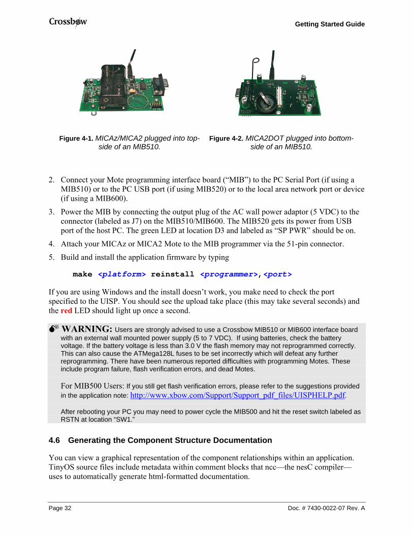
1. Connect the 51-pin male connector of the MICAz/MICA2 to the 51-pin female connector on the MIB programming board (see Figure 4-1).
Or to download into a MICA2DOT,
1. Connect the female connectors of the MICA2DOT to the male connectors of the MIB’s MICA2DOT programming bay located on the “underside” of the MIB programming board (see Figure 4-2).
NOTE: The Professional MOTE-KITs come with two MDA500 data acquisition boards. These are circular PCBs populated only with 19 pins. These can be used to make it easier to attach a MICA2DOT to the MIB510. This is done by connecting the 19-pin female-side of the MDA500 to the 19 male pins on the MIB510. The flexibility of the board and pins of the MDA500 helps to make up for small misalignments between the boards and avoids bending of pins on MIB510.
WARNING: When programming a MICAz, MICA2 with the MIB510/MIB520, turn OFF the battery switch. For a MICA2DOT, remove the battery before inserting into the MIB510/MIB520. The MICAz, MICA2s, and MICA2DOTs do not have switching diodes to switch between external and battery power.
Doc. # 7430-0022-07 Rev. A Page 31
Getting Started Guide
Figure 4-1. MICAz/MICA2 plugged into top-side of an MIB510.
Figure 4-2. MICA2DOT plugged into bottom-side of an MIB510.
2. Connect your Mote programming interface board (“MIB”) to the PC Serial Port (if using a MIB510) or to the PC USB port (if using MIB520) or to the local area network port or device (if using a MIB600).
3. Power the MIB by connecting the output plug of the AC wall power adaptor (5 VDC) to the connector (labeled as J7) on the MIB510/MIB600. The MIB520 gets its power from USB port of the host PC. The green LED at location D3 and labeled as “SP PWR” should be on.
4. Attach your MICAz or MICA2 Mote to the MIB programmer via the 51-pin connector.
5. Build and install the application firmware by typing
make <platform> reinstall <programmer>,<port>
If you are using Windows and the install doesn’t work, you make need to check the port specified to the UISP. You should see the upload take place (this may take several seconds) and the red LED should light up once a second.
WARNING: Users are strongly advised to use a Crossbow MIB510 or MIB600 interface board with an external wall mounted power supply (5 to 7 VDC). If using batteries, check the battery voltage. If the battery voltage is less than 3.0 V the flash memory may not reprogrammed correctly. This can also cause the ATMega128L fuses to be set incorrectly which will defeat any further reprogramming. There have been numerous reported difficulties with programming Motes. These include program failure, flash verification errors, and dead Motes.
For MIB500 Users: If you still get flash verification errors, please refer to the suggestions provided in the application note: http://www.xbow.com/Support/Support_pdf_files/UISPHELP.pdf.
After rebooting your PC you may need to power cycle the MIB500 and hit the reset switch labeled as RSTN at location “SW1.”
4.6 Generating the Component Structure Documentation
You can view a graphical representation of the component relationships within an application. TinyOS source files include metadata within comment blocks that ncc—the nesC compiler—uses to automatically generate html-formatted documentation.
Page 32 Doc. # 7430-0022-07 Rev. A

Getting Started Guide
To generate the documentation, go to the tinyos-1.x/contrib./xbow/apps/Blink/ directory use the following command:
make <platform> docs
The resulting documentation will have the filename be generated in the file docs/nesdoc/<platform>.docs/nesdoc/<platform>/index.html. This is the main index to all documented applications.
The directory index takes you to an html file that looks like the diagram shown below.
Apps Components Interfaces All Files Source Tree
App: Blink
Component Graph (text version, help)
Main
BlinkMLedsC
SingleTimer
StdControl
StdControl
Leds
Timer
Browsing through the graphical representation of the component wiring using your mouse is really helpful to understand the overall structure of TinyOS.
4.7 Radio Communications
This Section introduces radio communication. The applications that we will consider are CntToLedsAndRfm and RfmToLeds. CntToLedsAndRfm is a variant of Blink. It outputs the current counter value to two output interfaces: the LEDs and the radio communication stack. RfmToLeds receives data from the radio and displays it on the LEDs. Programming one Mote with CntToLedsAndRfm will cause it to transmit its counter value over the radio; programming another with RfmToLeds causes it to display the received counter on its LEDs. (For more details on different component modules, look at Lesson 4 of the TinyOS Tutorial.)
IMPORTANT: If you’re using MICA2 or MICA2DOT Motes, you will need to ensure that you’ve selected a radio frequency compatible with your Motes. If your Motes do not communicate in this Section, the likely reason is that you don’t have your frequency set correctly. Refer back to Section 3.6 on how to set the radio frequency.
MICAz currently uses IEEE 802.15.4 channel 0 (2.405 GHz) and ignores DCC1K_DEF_FREQ.
4.7.1 Sending Messages with CntToLedsAndRfm 1. Change your directory to the CntToLedsAndRfm directory (inside a Cygwin window).
Doc. # 7430-0022-07 Rev. A Page 33

Getting Started Guide
cd /opt/tinyos-1.x/contrib/xbow/apps/CntToLedsAndRfm
2. Attach a Mote to your programming board. Build and install the application. make <platform> install <programmer>,<port>
3. Remove the Mote from the MIB programmer, install batteries if needed, and turn on. Assuming you have batteries are OK, you should see a 3-bit binary counter on the LEDs. And while it is not apparent, it is, of course, transmitting the value over the radio.
4.7.2 Receiving Messages with RfmToLeds 4. Attach a second Mote to an MIB programming board.
5. Change directory to RfmToLeds. Build and install the application. cd ../RfmToLeds
make <platform> install <programmer>,<port>
6. Remove the Mote from the MIB and turn on.
If you turn the Mote with CntToLedsAndRfm, you will see that the LED counting stops on both Motes.
4.7.3 Radio Transmit/Receive FAQ There are many several reasons why you might not be able to communicate. Here are some things to check if you can’t get your Motes to communicate with these two applications.
Correct radio frequency? Be sure that you have set the radio frequency (channel) correctly in your MakeXbowlocal file.
Correct group ID? Motes on the same channel but different group IDs will not be able to communicate with each other.
Base station switch set to transmit only? If the switch labeled “SW2” is in the “ON” position, the MIB will only transmit but not receive.
RF null location? Move your Mote to a slightly different location or about ± 1m.
RF overload? You may have too many Motes close to each other. Or you may be near a strong RF source such as a major airport or radio transmitters.
Antennas installed and correctly oriented? Motes without antennas will not have much success in transmitting or receiving signals beyond a few cm. Typically you should have your antennas mounted vertically with respect to the ground. In rare cases, the antennas itself may be faulty; try other antennas to see if performance improves.
Motes’ radio TX/RX range exceeded? If none of the above apply, you may have to place your Motes closer together. In fact one of the practical uses of these two applications is to do a crude TX/RX site survey. This is done by placing the Mote with CntToLedsAndRfm in one location. Move the Mote with RfmToLeds until you stop seeing the 3-bit binary count. This would be an approximate distance to for one hop between two Motes.
NOTE: You may have to place the Mote with RfmToLeds on a surface and step away since your body is a source of radio interference.
Page 34 Doc. # 7430-0022-07 Rev. A

Getting Started Guide
4.8 Learning More About TinyOS and nesC
This section was only a brief introduction to some of the concepts in TinyOS and nesC. An online version of the tutorial for a more complete introduction to TinyOS is at
http://www.tinyos.net/tinyos-1.x/doc/tutorial/
IMPORTANT:
Please note that the tutorial references the applications reference to tinyos-1.x/apps found under the main tree. These are public domain applications and Crossbow assumes no responsibility for the support. Hence the support needs to be obtained from TinyOS help group. For more details go to, http://www.tinyos.net/ or e-mail [email protected]
Doc. # 7430-0022-07 Rev. A Page 35

Getting Started Guide
5 Test Applications and Drivers for Sensor and Data Acquisition Boards
WARNING: To use these test applications and drivers, you must update to TinyOS 1.1.10 as described in Chapter 2 of this Guide.
This Chapter will help you test your sensor and data acquisition boards. A set of test applications and a corresponding UI called XListen are provided to enable user’s to do basic testing and verification of their sensor and data acquisition (DAQ) boards. The XListen program displays a sensor’s or DAQ’s output in a Cygwin window. Listed in the Table 5-1 are TinyOS test application and drivers to evaluate your the sensor and/or DAQ board.
Table 5-1. Test and/or Demo Applications and Drivers for Crossbow’s Sensor and Data Acquisition Boards
Sensor or DAQ Board Test/Demo Application Driver Name MTS101 XSensorMTS101 basicsb
XSensorMTS510 MTS510
Surge_Reliable_Dot mts510
XSensorMDA500 MDA500
Surge_Reliable_Dot basicsb1
MTS300/310 Surge_Reliable mts310 MTS400/420 XSensorMTS400 mts400
MDA300 XSensorMDA300 mda300 1basicsb drivers are located in the tinyos/cygwin/opt/tinyos-1.x/tos/sensoboards/ directory, whereas the other drivers are in the tinyos/cygwin/opt/tinyos-.x/contrib/xbow/tos/sensorboards/ directory.
5.1 Drivers
A driver is a set of software code modules written in nesC which supports the lower level functionality of the sensor board. This is needed by all TinyOS applications. Driver code is typically developed during the sensor board design stage. These drivers should be in the opt/tinyos-1.x/contrib/xbow/tos/sensorboards/ directory.
IMPORTANT: Follow the instructions per Section 2.2.4 if you have not installed Crossbow’s TinyOS subdirectories.
5.2 Test Applications: The XSensor Series
The XSensor series of test applications was developed to quickly and easily test Crossbow sensor and/or data acquisition boards. Furthermore, these applications are a set of well-documented code modules, which users can modify for their own TinyOS applications.
To install a test application, navigate to opt/tinyos-1.x/contrib/xbow/apps and change to the directory that corresponds to the sensor board you want to test. The Mote hardware functionality can be tested in two different ways:
Page 36 Doc. # 7430-0022-07 Rev. A

Getting Started Guide
Over the UART (Universal Asynchronous Receive Transmit): See Section 5.2.1.
Over an RF (Radio Frequency) link: See Section 5.2.2.
5.2.1 Testing a Sensor Board over the UART Testing your sensor board over the UART bypasses the need for an RF link. This test is useful if you want to test the sensor board without having to deal with possible radio problems. It also requires only one Mote, and you only have to program the Mote with an appropriate XSensor application.
EXAMPLE—Installing XSensorMDA500 Test Application for the MICA2DOT on a MIB510 on serial port COM1. Change your directory to the test application.
cd /opt/tinyos-1.x/contrib/xbow/apps/XSensorMDA500
Attach a MICA2DOT to the bottom side pins on the MIB. Build and install the application to the Mote (with unique node ID other than 0).
make mica2dot install,1 mib510,com1
where 1 is the node ID.
Read Section 5.3 to run the text user-interface program XListen. Make sure that the switch labeled “SW2” on the MIB510 is on the “OFF” position.
5.2.2 Testing a Sensor Board by Wireless (RF) Link Testing your sensor board over the RF link requires two Motes. The Mote with the sensor/data acquisition board attached to it will have the test firmware installed. The other Mote will be programmed with an application called TOSBase (in /opt/tinyos-1.x/contrib./xbow/apps/). Assuming you have successfully completed the exercises in Chapter 4, you should be confident about having the frequencies set correctly.
1. If you have a sensor node (Mote + sensor board) on the MIB, remove it. Install batteries in it if needed. Make sure the battery switch is in the “ON” position for the MICA2.
2. Attach a either a MICA2 or MICA2DOT to the appropriate connector on the MIB.
NOTE: Unlike most other TinyOS applications, the MICA2DOT can be used as a base station Mote. This applies only for the XSensor Series test applications. It is important to use the proper baud rate which is discussed in Section 5.3.2 below.
3. Change your directory to the TOSBase directory which is in /opt/tinyos-1.x/contrib./xbow/apps/.
cdapps
cd TOSBase
4. Build and install the TOSBase to the Mote (with node ID 0). make mica2dot install,0 <programmer>,<port>
Doc. # 7430-0022-07 Rev. A Page 37

Getting Started Guide
Read Section 5.3.2 to run the text user-interface program XListen. Make sure that the switch labeled “SW2” on the MIB510 is on the “OFF” position.
5.3 User Interface: XListen
The user interface is a PC-based tool used to view sensor data. XListen is a Cygwin C console program written in C that receives RS232/radio packets from the Mote and converts to engineering units. XListen is used only to verify that the sensor board is working properly. It is not a sensor network program. This program is located in /opt/tinyos-1.x/contrib/xbow/tools/src/xlisten. By default, you must be that src/ subdirectory to run XListen. To run XListen from anywhere in the Cygwin shell, do the following in a Cygwin shell: 1. cd /usr/local/bin 2. ln -s /opt/tinyos-
1.x/contrib/xbow/tools/src/xlisten/xlisten.exe xlisten
The source code for XListen is in the tinyos/cygwin/opt/tinyos-1.x/contrib/xbow/tools/src/xlisten/ directory for user modification and editing.
5.3.1 Help List for XListen XListen has many modes of operation that can be controlled by passing command line parameters. Help on finding the commands for XListen can be found by typing in xlisten -? in a Cygwin window (see the text output below).
$ xlisten -? xlisten Ver:$Id: xlisten.c,v 1.12 2004/08/05 01:35:35 mturon Exp $ Using params: [help] Usage: xlisten <-?|r|p|x|c|d|q> <-b=baud> <-s=device> -? = display help [help] -r = raw display of tos packets [raw] -p = parse packet into raw sensor readings [parsed] -x = export readings in csv spreadsheet format [export] -c = convert data to engineering units [cooked] -l = log data to a database or file [logged] -d = debug serial port by dumping bytes [debug] -b = set the baudrate [baud=#|mica2|mica2dot] -s = set serial port device [device=com1] -h = specify header size [header=offset] -q = quiet mode (suppress headers) -v = show versions of all modules
5.3.2 Baud rate: -b=[baudrate] This flag allows the user to set the baud rate of the serial line connection. The default baud rate is 57,600 bits per second (bps) which is compatible with the MICAz/MICA2. The desired baud rate must be passed as a number directly after the equals sign with no spaces in between, i.e., –b=19200.
Optionally, a product name can be passed in lieu of an actual number and the proper baud will be set, i.e., –b=mica2dot. Valid variables are in
Page 38 Doc. # 7430-0022-07 Rev. A

Getting Started Guide
Table 5-2. Valid variables and baud rates for the –b option
Mote Baud Rate Variable MICAz/MICA2 57600 mica2
MICA2DOT 19200 mica2dot
5.3.3 Serial port: –s=port [serial] This flag gives the user the ability to specify which COM port or device XListen should use. The default port is /dev/ttyS0 or the UNIX equivalent to COM1. The given port must be passed directly after the equals sign with no spaces, e.g., –s=com3.
5.3.4 Raw data values: –r Raw mode displays the actual TOS packets as a sequence of bytes as seen coming over the serial line.
EXAMPLE—Raw text output with xlisten -r $ xlisten -r xlisten Ver:$Id: xlisten.c,v 1.7 2004/03/23 00:52:28 crossbow Exp $ Using params: [raw] /dev/ttyS0 input stream opened 7e7e000033000000c8035f61d383036100000000e4510d610000000080070000d4b5f577 7e00007d1d8101060029091e09ef082209e7080b09b40800000000000000000000000100 7e00007d1d81020600f007de07da07d507c3064706540500000000000000000000000100
Examining the second line from the output example above, the values are interpreted as:
Packet Byte Name Example Notes
TOS Header = 7e00007d1d
UART Addess 7e00 Type 00
Group ID 7d Default
Data Payload = 8101060029091e09ef082209e7080b09b408000000000000000000
sensorboard_id 81 MDA300 packet_id 01
node_id 06 reserved 00
Data 29091e09ef082209e7080b09b408000000000000000000
Depends on sensorboard_id and packet_id. In this case it is the raw ADC values for an MDA500.
Doc. # 7430-0022-07 Rev. A Page 39

Getting Started Guide
Table 5-3. The TinyOS files that define this data packet
TinyOS file Information tos/types/AM TOS_msg header
contrib/xbow/tools/src/xlisten/xsensor.h Xbow sensor packet contrib/xbow/tools/src/xlisten/boards Sensor/DAQ board specific data payloads
5.3.5 Cooked data values: –c Cooked mode converts the raw sensor readings within a given packet into engineering units.
EXAMPLE—Raw text output with xlisten –c –b=mica2dot on a MICA2DOT programmed with XSensorMDA500. $ xlisten -c -b=mica2dot xlisten Ver:$Id: xlisten.c,v 1.7 2004/03/23 00:52:28 crossbow Exp $ Using params: [baud=0x000e] [cooked] /dev/ttyS0 input stream opened MDA500 [sensor data converted to engineering units]:
health: node id=6 battery: volts=3163 mv thermistor: resistance=10177 ohms, tempurature=24.61 C adc chan 2: voltage=1258 mv adc chan 3: voltage=1001 mv adc chan 4: voltage=893 mv adc chan 5: voltage=939 mv adc chan 6: voltage=875 mv adc chan 7: voltage=850 mv
5.3.6 Quiet Mode: –q This flag suppresses the standard XListen header which displays the version string and parameter selections.
5.3.7 Exporting Data Readings: –x Export mode displays raw analog to digital converter (ADC) values as comma delimited text for use in spreadsheet and data manipulation programs. The user can redirect the screen output of XListen by using a “> log_filename” to write file. Later that log_filename can be read by Microsoft® Excel to build charts of the information.
EXAMPLE—Printing to screen (standard output) with xlisten –x on a MICA2DOT $ xlisten -b=mica2dot -q –x 51200,24323,54113,899,97,0,58368,3409 6,193,518,409,328,283,296,298 6,194,517,410,330,292,310,300 6,194,518,409,329,286,309,288 6,194,517,411,331,287,297,300 6,194,516,413,335,288,301,287
Page 40 Doc. # 7430-0022-07 Rev. A

Getting Started Guide
5.3.8 Debugging: –d This flag puts XListen in a mode so that it behaves exactly like the TinyOS raw listen tool (opt/tinyos-1.x/contrib/xbow/tools/src/raw_listen.c). All other command line options except –b (baud rate) and –s (UART serial port) will be ignored. This mode is mainly used for compatibility and debugging serial port issues. Individual bytes will be displayed as soon as they are read from the serial port with no post-processing. In most cases -r (raw ADC readings) is equivalent and preferred to using debug mode.
5.3.9 Display Options The -r, -p, and -c flags are considered display options. These can be passed in various combinations to display multiple views of the same packet at once. The default display mode when XListen is invoked with no arguments is -r.
EXAMPLE—Output with xlisten –r –p -c $ xlisten -b=mica2dot -r -p -c xlisten Ver:$Id: xlisten.c,v 1.7 2004/03/23 00:52:28 crossbow Exp $ Using params: [baud=0x000e] [raw] [parsed] [cooked] /dev/ttyS0 input stream opened 7e7e000033000000c8035f61d383036100000000e4510d610000000080070000d4b5f577 7e00007d1d01010600c200050293014401210135012f0122010000000000000000000100 mda500 id=06 bat=00c2 thrm=0205 a2=0193 a3=0144 a4=0121 a5=0135 a6=012f a7=0122 MDA500 [sensor data converted to engineering units]: health: node id=6 battery: volts=3163 mv thermistor: resistance=10217 ohms, tempurature=24.53 C adc chan 2: voltage=1246 mv adc chan 3: voltage=1001 mv adc chan 4: voltage=893 mv adc chan 5: voltage=955 mv adc chan 6: voltage=936 mv adc chan 7: voltage=896 mv
5.4 Example Output from XSensorMTS400
$ xlisten -r -p -c -b=mica2 -s=com1 xlisten Ver:$Id: xlisten.c,v 1.9 2004/04/08 01:35:35 crossbow Exp $ Using params: [baud=0x1001] [raw] [parsed] [cooked] com1 input stream opened 7e0000201d860101007d019803bf1aaccc1eabe3aacad090686545a30000000002e50100 mts420 id=01 battery=017d humidity=0398 temp=1abf intersema calibration words(1..4) = ccac,ab1e,aae3,d0ca intersematemp=6890 intersemapressure=4565 taosch0=00a3 taosch1=0000 accel_x=0200 accel_y=01e5 MTS420 [sensor data converted to engineering units]: health: node id = 1 battery: = 3287 mv humidity: = 31 % Temperature: = 28 degC IntersemaTemperature: = 28 degC IntersemaPressure: = 1007 mbar
Doc. # 7430-0022-07 Rev. A Page 41

Getting Started Guide
Light: = 28.059999 lux X-axis Accel: = 583.333313 mg Y-axis Accel: = 81.218269 mg
NOTE: When connected to the computer via serial COM to UART, GPS data was not available, so non-GPS sensor data readings are shown above. In order to receive/display the GPS data you must uncomment #define MTS420 line in sensorboardApp.h file found under tinyos-1.x/contrib./xbow/apps/XSensorMTS400
5.5 Example Output from XSensorMTS510
Crossbow@wireless_dev /opt/cvs-src_tinyos-1.x/contrib/xbow $ xlisten -r -p -c -b=mica2dot -s=com1 xlisten Ver:$Id: xlisten.c,v 1.9 2004/04/08 01:35:35 crossbow Exp $ Using params: [baud=0x000e] [raw] [parsed] [cooked] com1 input stream opened 7e0000201d020105008303f4010302550154015401540155010000000000000000000100 mts510 id=05 light=0383 acc_x=01f4 acc_y=0203 sound[0]=155 sound[1]=154 sound[2]=154 sound[3]=154 sound[4]=155 MTS510 [sensor data converted to engineering units]: health: node id=5 light: =899 ADC counts X-axis Accel: =-0.016129 g Y-axis Accel: =0.114754 g
5.6 Example Output from XSensorMDA300
$ xlisten -r -p -c -b=mica2dot -s=com1 xlisten Ver:$Id: xlisten.c,v 1.9 2004/04/08 01:35:35 crossbow Exp $ Using params: [baud=0x000e] [raw] [parsed] [cooked] com1 input stream opened 7e0000811d01010400c100e1014001fa00d500fa00ee00b8000000000000000000000100 Mda300 id=04 bat=00c1 thrm=01e1 a2=0140 a3=00fa a4=00d5 a5=00fa a6=00ee a7=00b8 MDA300 [sensor data converted to engineering units]: health: node id=4 battery: volts=3183 mv thermistor: resistance=8874 ohms, tempurature=27.53 C adc chan 2: voltage=995 mv adc chan 3: voltage=777 mv adc chan 4: voltage=662 mv adc chan 5: voltage=777 mv adc chan 6: voltage=740 mv adc chan 7: voltage=572 mv
5.7 Example Output from XSensorMDA500
$ xlisten -r -p -c -b=mica2dot -s=com1 xlisten Ver:$Id: xlisten.c,v 1.9 2004/04/08 01:35:35 crossbow Exp $ Using params: [baud=0x000e] [raw] [parsed] [cooked] com1 input stream opened 7e0000811d01010400c100e1014001fa00d500fa00ee00b8000000000000000000000100 mda500 id=04 bat=00c1 thrm=01e1 a2=0140 a3=00fa a4=00d5 a5=00fa a6=00ee a7=00b8 MDA500 [sensor data converted to engineering units]:
Page 42 Doc. # 7430-0022-07 Rev. A

Getting Started Guide
health: node id=4 battery: volts=3183 mv thermistor: resistance=8874 ohms, tempurature=27.53 C adc chan 2: voltage=995 mv adc chan 3: voltage=777 mv adc chan 4: voltage=662 mv adc chan 5: voltage=777 mv adc chan 6: voltage=740 mv adc chan 7: voltage=572 mv
Doc. # 7430-0022-07 Rev. A Page 43

Getting Started Guide
6 Surge Multi-hop Networking Application
The TinyOS-1.1.0 release and later include library components that provide ad-hoc multi-hop routing for sensor network applications. The implementation uses a shortest-path-first algorithm with a single destination node (the root) and active two-way link estimation. The data movement and route decision engines are split into separate components with a single interface between them to permit other route-decision schemes to be easily integrated in the future. Use of the multi-hop router is essentially transparent to applications (provided they correctly use the interface).
6.1 How does Surge Multi-hop network work?
Crossbow’s mesh networking resides as a software component in TinyOS. Typical applications that run on the Motes use several different software components―e.g., sensor components, data logging, and more. If the application is going to use mesh networking, it will link in the MultiHopRouter software component. The implementation of the MultiHopRouter component found in Crossbow’s TinyOS contribution directory includes some significant performance upgrades, and it is a state-of-the-art mesh networking algorithm.
Figure 6-1. A Graphviz representation of the TinyOS application Surge_Reliable and Surge_Reliable_Dot
The MultiHop router component automatically transmits link quality estimates, publishes distance estimates, performs optimal route selection and forwards multi-hop data traffic. Pictured in Figure 6-1, the routing component is divided into two major pieces: the MultiHopEngineM and the MultiHopLEPSM component. Additionally, it uses the QueueSend component, the TimerC component and the GenericCommPromiscuous component to properly perform its duties. The MultiHopEngineM component implements the core forwarding and sending function of multi-hop routing. Once a parent has been determined, the MultiHopEngineM properly receives updates and transmits the data packet on towards its final destination. Upon receipt of a Multi-hop packet, the MultiHopEngineM forwards the packet if and only if it was directly addressed to the node via the packet addressing mechanism. If so, the engine uses the MultiHopLEPSM to select the next hop destination and updates the packet by using the RouteSelect interface. Once the MultiHopLEPSM has updated the fields of the multi-hop packet, the packet is handed to the QueueSend for transmission as soon as possible. The
Page 44 Doc. # 7430-0022-07 Rev. A

Getting Started Guide
QueueSend is a simple component that will accept multiple transmission requests and perform the actual transmissions as the channel allows.
The data movement and route decision engines are split into separate components with a single interface between them to permit other route-decision schemes to be easily integrated in the future. Use the MultiHopRouter is essentially transparent to applications (provided they correctly use the interface).
Use of the multi-hop library component is mostly transparent to the application. Any application that uses the Send interface can be connected to this component to achieve multi-hop functionality. One limitation of multi-hop, however, is the aggregate data rate. Applications should maintain average message frequency at or slower than one message every two seconds. Higher rates can lead to congestion and/or overflow of the communication queue.
6.2 Programming Motes with Surge_Reliable
To program additional MICAz (Section 6.2.1) or MICA2 (Section 6.2.2) Motes with Surge_Reliable and additional MICA2DOTs (Section 6.2.3) with Surge_Reliable_Dot. You’ll need to install TinyOS 1.1.0 and then the TinyOS 1.1.10 RPM update onto your PC. Follow the instructions per Section 2.2.4 if you have not installed Crossbow’s TinyOS subdirectories.
NOTE: Remember, the Mote used as the network base station must be a MICA2 or MICAz programmed with a node address, <nodeid>, of 0 (zero).
6.2.1 Installing Surge_Reliable on MICAz Mote The key to building Surge_Reliable in TinyOS 1.1.10 for the MICAz is to make certain that Surge_Reliable’s makefile uses the new Makerules in {TOSROOT}/tools/make/.
COMPONENT=Surge SENSORBOARD=micasb #TINYSEC=true # For MICA2 and MICA2DOT # PFLAGS+= -I../../tos/platform/mica2 -I../../tos/CC1000RadioAck -I../../tos/lib/ReliableRoute -I%T/lib/Queue -I%T/lib/Broadcast -I%T/lib/Attributes # For MICAZ # PFLAGS+= -I../../beta/tos/lib/CC2420RadioAck -I../../beta/tos/platform/micazack -I../../tos/lib/ReliableRoute -I%T/lib/Queue -I%T/lib/Broadcast -I%T/lib/Attributes include ../MakeXbowlocal include ${TOSROOT}/tools/make/Makerules
TINYSEC only works for MICA2/MICA2DOT Motes
For MICA2 users, uncomment this line.
For MICAz users, uncomment this line.
Figure 6-2. The makefile for Surge_Reliable. Text boxes highlight where to comment/uncomment for proper compiling of the application for MICA2 and MICAz Motes
1. Edit Surge_Reliable’s makefile by uncommenting the corresponding line for MICA2 as shown in Figure 6-2.
Doc. # 7430-0022-07 Rev. A Page 45

Getting Started Guide
2. Open a Cygwin window.
3. Change directory to the tinyos-1.x/contrib/xbow/apps/Surge_Reliable.
cd /opt/tinyos-1.x/contrib/xbow/apps/Surge_Reliable
4. Build the application.
make micaz
5. Download (flash) the MICAz with the application. Be sure to attach the MICAz Mote on the MIB510 before typing in this command.
make micaz reinstall,<nodeid> <programmer>,<port>
where <nodeid> is the node address you want that Mote to be and <#> is the serial port number to which the MIB510 is connected. Repeat this step for as many Motes you need to have programmed.
NOTE: The TINYSEC variable in the above Makefile sets the network security for MICA2 motes. The MICA2DOTs currently do not support this feature. Hence it is important that you comment out this line when using MICA2DOTs in the MICA2 network. Otherwise, MICA2DOTs won’t be able to join the network!
6.2.2 Installing Surge_Reliable on MICA2 Motes 1. Edit Makefile to uncomment the corresponding line for MICAz as shown above.
2. Open a Cygwin window. Change directory to the tinyos-1.x/contrib/xbow/apps/Surge_Reliable.
cd /opt/tinyos-1.x/contrib/xbow/apps/Surge_Reliable
3. Build the application. make mica2
4. Download (flash) the application into a MICA2: attach a MICA2 Mote into the 51-pin connector on the MIB.
make mica2 reinstall,<nodeid> <programmer>,<port>
5. Repeat until you have installed all the MICA2 Motes.
6.2.3 Installing Surge_Reliable_Dot on MICA2DOT Motes 1. Open a Cygwin window. Change directory to tinyos-
1.x/contrib/xbow/apps/Surge_Reliable. cd /opt/tinyos-1.x/contrib/xbow/apps/Surge_Reliable_Dot
2. Build the application. make mica2dot
3. Install the application into a MICA2DOT: attach a MICA2DOT Mote into the 19 pin connector on the MIB510.
Page 46 Doc. # 7430-0022-07 Rev. A

Getting Started Guide
make mica2dot reinstall,<nodeid> <programmer>,<port>
The <nodeid> should be never be 0 for a MICA2DOT and needs to be different than the numbers you gave for the MICA2s.
6.2.4 Changing the Transmit Rate in Surge_Reliable or Surge_Reliable_Dot You can change the tranmsit rate of the Motes running Surge_Reliable or Surge_Reliable_Dot Below is the portion of Surge.h located in both the Surge_Reliable and the Surge_Reliable_Dot directories. Specifically, change line 33 which has the variable “INITIAL_TIMER_RATE.” The number represents time in milliseconds. In that line, the transmit rate is determined by multiplying 1024 by some integeter value greater than or equal to two.
EXAMPLE—Part of the Surge.h file in Surge_Reliable_Dot/
* This file is distributed under the terms in the attached INTEL-LICENSE * file. If you do not find these files, copies can be found by writing to * Intel Research Berkeley, 2150 Shattuck Avenue, Suite 1300, Berkeley, CA, * 94704. Attention: Intel License Inquiry. */
Change the “2” in line 33 to another number. (Try “8”.)
enum{ INITIAL_TIMER_RATE = 1024 * 2, FOCUS_TIMER_RATE = 1000, FOCUS_NOTME_TIMER_RATE = 1000 };
6.3 Running Surge-View GUI
Follow the instructions provided in Chapter 1 of the guide to run the GUI to visualize the network topology.
Doc. # 7430-0022-07 Rev. A Page 47

Getting Started Guide
7 Appendix A. Warranty and Support Information
7.1 Customer Service As a Crossbow Technology customer you have access to product support services, which include:
• Single-point return service
• Web-based support service
• Same day troubleshooting assistance
• Worldwide Crossbow representation
• Onsite and factory training available
• Preventative maintenance and repair programs
• Installation assistance available
7.2 Contact Directory United States: Phone: 1-408-965-3300 (8 AM to 5 PM PST)
Fax: 1-408-324-4840 (24 hours)
Email: [email protected]
Non-U.S.: refer to website www.xbow.com
7.3 Return Procedure
7.3.1 Authorization Before returning any equipment, please contact Crossbow to obtain a Returned Material Authorization number (RMA).
Be ready to provide the following information when requesting a RMA:
• Name
• Address
• Telephone, Fax, Email
• Equipment Model Number
• Equipment Serial Number
• Installation Date
• Failure Date
• Fault Description
Page 48 Doc. # 7430-0022-07 Rev. A

Getting Started Guide
7.3.2 Identification and Protection If the equipment is to be shipped to Crossbow for service or repair, please attach a tag TO THE EQUIPMENT, as well as the shipping container(s), identifying the owner. Also indicate the service or repair required, the problems encountered and other information considered valuable to the service facility such as the list of information provided to request the RMA number.
Place the equipment in the original shipping container(s), making sure there is adequate packing around all sides of the equipment. If the original shipping containers were discarded, use heavy boxes with adequate padding and protection.
7.3.3 Sealing the Container Seal the shipping container(s) with heavy tape or metal bands strong enough to handle the weight of the equipment and the container.
7.3.4 Marking Please write the words, “FRAGILE, DELICATE INSTRUMENT” in several places on the outside of the shipping container(s). In all correspondence, please refer to the equipment by the model number, the serial number, and the RMA number.
7.3.5 Return Shipping Address Use the following address for all returned products:
Crossbow Technology, Inc. 4145 N. First Street San Jose, CA 95134 Attn: RMA Number (XXXXXX)
7.4 Warranty The Crossbow product warranty is one year from date of shipment.
Doc. # 7430-0022-07 Rev. A Page 49


Crossbow Technology, Inc.4145 N. First Street San Jose, CA 95134 Phone: 408.965.3300 Fax: 408.324.4840 Email: [email protected]