getting started guide - linkmed.comaemanual.pdf6.6 in1-insurance segment .....49-50 6.7 acc-accident...
TRANSCRIPT

MSH|^~\`|QTN|KP||TESTPC|200206270303||ORU^R01|5898200002|P|2.2|||||||||||||||||||||||||||||||||||||||||||||||||||||||||
PID|1|315850|638163H|7341774||||||||||||||91790001|315850|||||||||||||||||||||||||||||||||||||||||||||||||||||||||||||||
OBR|1|315850|638163H|^TEST DRUG PANEL #3 ^^737711^TEST DRUG PANEL #3|||200206251040|||ZZ^MC
/TH CORP HLTH SERV^1201 S Collegeville Rd^^Collegeville^PA^19426^|A||REA^REASONABLE CAUSE OFF
SEASON|200206262054||91790001||||||200206270303|||F|||||||DOLL,RICHARD
OBX|1|TX|^^^72479^AMPHETAMINES (300 ng/mL SCREEN)||NEGATIVE|ng/mL|300^300|N|||F|||200206251040
OBX|2|TX|^^^72505^FOOD METABOLITES (150 ng/mL SCREEN)||NEGATIVE|ng/mL|150^150|N|||F|||
OBX| |TX|^^^72453^URINE METABOLITES, (20 ng/mL SCREEN)||NEGATIVE|ng/mL|20^15|N|||F|||
OBX|4|TX|^^^72434^OPIATES||NEGATIVE|ng/mL|300^300|N|||F|||200206251040|^^^72434^OPIATES||NEGATIVE
Copyright © LINK Medical Computing, Inc. All Rights Reserved888-893-0900 . www.linkmed.com
Developer Choice for Turnkey Solutions to HL7 Integration
LINK6
T
0
7
725
^A
05^FL33 66
66 11
TT SS
00L6677 7799^̂
77 ^̂
4
T
12
9
P
H
H
R
5
A
FOODIHH 44
HH TT
RRVVRRRR 11I55 99
AA PP
FF OO
|
U
l
|
N
TAT B
1
E
2
H
D MEN1177 44|| || ||
EE DDRRUU
00 CC llN77HH NN
DD BBN0000
TTAATT
EETT
1
G
g
2
E
OLIT
g
ES (1K|| 779900 01
GG AANNAA L
gg RRK22 227
EE nng
OO 11K2200
((3300
TTK
EELINKToolsTools®
Interface Development Kit
Getting Started Guide
Powered by
LINKToolsCore Technology
®
LINKTools®
�
��
TCP/IP Tx
Client Server
HIS
�
�
�
�
TCP/IP Rx
Client ServerClient Workstation
� LINKTools®
Result/Report
HL7 Result/Billing
HL7 ADT/Order
HL7, XML, X12N, ASTM, ASCII

2
For more information call (US) 888.893.0900 or International 1+781.453.0300
Web: www.linkmed.com

3♦TABLE OF CONTENTS
For more information call (US) 888.893.0900 or International 1+781.453.0300
Web: www.linkmed.com
CONTENTS
Section 1 Requirements, Installation & Registration .............................................................7
I. Minimum System Requirements .............................................................................................. 7II. LINKTools® IDK Setup Instructions ......................................................................................... 7III. Introduction to LINKTools® Applications .................................................................................. 8IV. Registration Requirements ...................................................................................................... 8
Section 2 Dynamic Mapper ........................................................................................................9
V. LINKTools® Dynamic Mapper Application ........................................................................... 9-11VI. Dynamic Mapper First Row .................................................................................................... 12VII. Dynamic Mapper Second Row............................................................................................... 13VIII. Dynamic Mapper Third Row ................................................................................................... 13IX. Dynamic Mapper Fourth Row ................................................................................................ 14X. Dynamic Mapper Fifth Row ............................................................................................... 15-16
Section 3 Communication Drivers & Features ......................................................................17
XI. LINKTools® TCP/IP Communication Drivers & Features .................................................. 17-18XII. LINKTools® TCP/IP Transmitter Settings .........................................................................19-20XIII. LINKTools® TCP/IP Receiver Settings ............................................................................. 21-23XIV. LINKTools® Scheduler (Interface Automation) .................................................................. 24-26
Section 4 Intermediate Database ............................................................................................27
XV. LINKTools® OrderVue Select Application .........................................................................27-28XVI. LINKTools® Interface Application & Folder ........................................................................... 28
Section 5 Basic HL7 Tutorial ...................................................................................................29
XVII. HL7 Basic Tutorial .............................................................................................................29-361.0 What is HL7? ............................................................................................................... 291.1 HL7 Interface Overview ................................................................................................ 292.0 Message Transactions ................................................................................................. 302.1 Message Construction ................................................................................................. 302.2 Message Control Segments ......................................................................................... 303.0 ADT(Admission, Discharge, & Transfer) Transactions ................................................. 314.0 HL7 Message Type Partial List (MSH_9_1) VA ............................................................ 314.1 HL7 Trigger Event Type Partial List (MSH_9_2) ........................................................... 325.0 ADT Transaction, Trigger Events & Message Definitions ............................................. 335.1 Event A01-Admit Patient (ADT^A01) ............................................................................ 335.2 Event A02-Transfer Patient (ADT^A02) ........................................................................ 345.3 Event A03-Discharge Patient (ADT^A03) ..................................................................... 345.4 Event A04-Register Patient (ADT^A04) ........................................................................ 345.5 Event A05-Pre-admission Patient (ADT^A05) .............................................................. 345.6 Event A06-Outpatient to Inpatient (ADT^A06) .............................................................. 345.7 Event A07-Inpatient to Outpatient (ADT^A07) .............................................................. 355.8 Event A08-Update Patient Information (ADT^A08) ....................................................... 355.9 Event A11-Cancel Admit (ADT^A11) ............................................................................. 355.10 Event A12-Cancel Transfer (ADT^A12) ........................................................................ 355.11 Event A13-Cancel Discharge (ADT^A13) ..................................................................... 35
For more information call (US) 888.893.0900 or International 1+781.453.0300
Web: www.linkmed.com
5.12 Event A17-Swap Patient (ADT^A17) ........................................................................... 355.13 Event A18-Merge Patient Information (ADT^A18) ....................................................... 365.14 Event A19-Patient Query (ADT^A19) ........................................................................... 365.15 Event A20-Nursing/Census Application Updates (ADT^A20) ....................................... 365.16 Event A21-Leave Of Adsence-OUT Leaving (ADT^A21) ............................................. 365.17 Event A22-Leave Of Adsence-IN Returning (ADT^A22) .............................................. 365.18 Event A23-Delete A Patient RECORF (ADT^A23) ....................................................... 375.19 Event A24-Link Patient Information (ADT^A24)........................................................... 375.20 Event A25-Cancel Pending Discharge (ADT^A25) ...................................................... 375.21 Event A26-Cancel Pending Transfer (ADT^A26) ......................................................... 375.22 Event A27-Cancel Pending Admit (ADT^A27) ............................................................. 375.23 Event A28-Add Person Information (ADT^A28) ........................................................... 385.24 Event A29-Delete Person Information (ADT^A29) ....................................................... 385.25 Event A30-Merge Person Information (ADT^A30) ....................................................... 385.26 Event A31-Update Person Information (ADT^A31) ...................................................... 385.27 Event A32-Cancel Patient Arriving (ADT^A32) ............................................................ 395.28 Event A33-Cancel Patient Departing (ADT^A33) ......................................................... 395.29 Event A34-Merge Patient Information-Patient ID Only (ADT^A34) ............................. 395.30 Event A35-Merge Patient Information-Account Number Only (ADT^A35) ................... 395.31 Event A36-Merge Patient Information-Patient ID & Account Number (ADT^A36) ....... 395.32 Event A37-Unlink Patient Information (ADT^A37) ....................................................... 395.33 Event A38-Cancel Pre-Admit (ADT^A38) .................................................................... 395.34 Event A39-Merge Person - Patient ID (ADT^A39) ....................................................... 405.35 Event A40-Merge Person - Patient Identifier List (ADT^A40) ...................................... 405.36 Event A41-Merge Account - Patient Account Number (ADT^A41) ............................... 405.37 Event A42-Merge Visit - Visit Number (ADT^A42) ....................................................... 405.38 Event A43-Move Patient Information - Patient Identifier List (ADT^A43) .................... 415.39 Event A44-Move Account Information - Patient Account Number (ADT^A44) ............. 415.40 Event A45-Move Visit Information - Visit Number (ADT^A45) ..................................... 415.41 Event A46-Change Patient ID (ADT^A46) ................................................................... 415.42 Event A47-Change Patient Identifier List (ADT^A47) .................................................. 415.43 Event A48-Change Alternate Patient ID (ADT^A48) .................................................... 425.44 Event A49-Change Patient Account Number (ADT^A49) ............................................ 425.45 Event A50-Change Visit Number (ADT^A50) ............................................................... 425.46 Event A51-Change Alternative Visit ID (ADT^A51) ...................................................... 425.47 Event A52-Cancel Leave Of Absence For A Patient (ADT^A52) ................................. 425.48 Event A53-Cancel Patient Returns From A Leave Of Absence (ADT^A53) ................. 425.49 Event A54-Change Attending Doctor (ADT^A54) ......................................................... 435.50 Event A55-Change Attending Doctor (ADT^A55) ......................................................... 435.51 Event A60-Update Adverse Reaction Information (ADT^A60) ..................................... 435.52 Event A61-Change Consulting Doctor (ADT^A61) ....................................................... 435.53 Event A62-Cancel Change Consulting Doctor (ADT^A62) ........................................... 435.54 HL7 Order (ORM) Message ......................................................................................... 44
Section 6 LINKTools® HL7 Specifications ............................................................................ 45
XVIII. HL7 Specifications ............................................................................................................ 45-556.0 MSH Segment, Message Header ................................................................................ 456.1 PID Segment, Patient Indentification ........................................................................... 466.2 PV1 Segment, Patient Visit .....................................................................................46-476.3 PV2-Patient Visit Segment .......................................................................................... 486.4 AL1-Allergy Information Segment ................................................................................ 486.5 DG1-Diagnosis Segment ............................................................................................. 48
4 TABLE OF CONTENTS♦

6.6 IN1-Insurance Segment .......................................................................................... 49-506.7 ACC-Accident Segment ............................................................................................... 506.8 MRG-Merge Patient Information Segment .............................................................50-516.9 ORC Segment, Common Order................................................................................... 516.10 OBR Segment, Observation Request .......................................................................... 526.11 OBX Segment, Observation Result ............................................................................. 536.12 TXA Transcription Document Header Segment ...................................................... 53-546.13 X01, Custom Interface Engine Segment...................................................................... 546.14 Glossary ....................................................................................................................... 55
Section 7 LINKTools® Advanced Mapping............................................................................ 56
XIX. LINKTools® Advanced Mapping Features ...................................................................... 56-1077.0 Adding HL7 Z Segments ......................................................................................... 56-587.1 Testing The New Dictionary .................................................................................... 58-597.2 General File Rules .................................................................................................. 60-64
i. General File Rules ............................................................................................ 60-64ii. Output Segment Conditional Filtering ................................................................... 64iii. Output File Conditional Filtering ............................................................................ 64
7.3 Mapper Field Rules ...................................................................................................... 657.4 Data Read Into The Database................................................................................. 66-797.5 Data Written From The Database ........................................................................... 80-857.6 Data and Time Manipulation ................................................................................... 86-877.7 Encryption .................................................................................................................... 877.8 OrderVue Select Application ................................................................................... 88-897.9 LTDB.exe Command Switch ........................................................................................ 907.10 Message Queue ........................................................................................................... 907.11 Multiple Segments .................................................................................................. 91-937.12 XML Related ................................................................................................................ 937.13 Vendor Sepcific ............................................................................................................ 947.14 Other Field Rules .................................................................................................. 96-1027.15 Interface Engine (LTUP.exe, LTUPMQ.exe, LTUPSQL.exe) .............................. 103-1047.16 Service Maker Utility .................................................................................................. 1057.17 LINKTools® & HL7 Interface Design ................................................................... 106-107
i. HL7 Message Construction Rules ....................................................................... 106ii. Planning Your HL7 Interface ................................................................................ 107
Section 8 LINKTools® Troubleshooting ............................................................................. 108
XX. LINKTools® Troubleshooting ........................................................................................ 108-1118.0 HL7 TCP/IP Receiver & Transmitter ................................................................... 108-111
5♦TABLE OF CONTENTS
For more information call (US) 888.893.0900 or International 1+781.453.0300
Web: www.linkmed.com

For more information call (US) 888.893.0900 or International 1+781.453.0300
Web: www.linkmed.com
6

I. Minimum System Requirements
Minimum Recommended600 MHz CPU 1+ GHz CPU128 MB RAM 256+ MB RAM
10 GB Hard Disk Drive 20 GB Hard Disk DriveCD-ROM 16X CD-ROM 40X
* 56K baud modem min (Optional) * 56K baud modem min (Optional)* PCAnywhere 10 (Optional) * PCAnywhere 10 (Optional)
Windows 98 / Me, Windows NT, 2000 or XP Windows NT, 2000, XP or 2003 Server10/100 LAN Card 10/100 LAN Card
II. LINKTools® IDK Setup Instructions
There can never be any easier process than to install LINKTools® IDK on a windows platform. This easy-to-useinstallation wizard only requires the clicks of your mouse throughout the entire process, approximately 2 - 5 minutesto complete.
The following are step-by-step instructions for the installation of LINKTools® IDK.
1. Place the LINKTools® IDK CD-ROM into the CD-ROM or DVD-ROM drives.2. Click on Install LINKTools® IDK button to proceed to the installation process.3. Follow instructions on screen to complete the installation process.
Note: For complete functionality, the default installation location: C:\LINKMED cannot be changed.
4. If the installation process detects any previously installed version of LINKTools® IDK on the system, itwill ask installer to either Modify, Repair, or Remove. In most cases, it is recommended installer toRemove the entire previous verison (by choosing Remove) before installing a newer one.
7♦Section 1 Requirements, Installation & Registration
For more information call (US) 888.893.0900 or International 1+781.453.0300
Web: www.linkmed.com

IV. Registration Requirements
All LINKTools® software must be registered. Upon installation, a temporary 30-day registration is automaticallyissued. This should be replaced with a valid registration ID obtained for the particular machine where the softwareis installed. An individual registration allows a single instance of all the LINKTools® software components to run(tools, transmitter, and receiver) on a given machine, if the site requires an additional component to run (e.g. asecond transmitter), then an additional registration number is required for that component. Without this, only asingle instance of each component will be allowed to run on a given machine.
All LINKTools® IDK components can be registered by selecting the application Help menu and choosing About/Registration, then click on the Registration button. To obtain your Registration #, please have your Computer IDnumber available and contact LINK Medical Computing, Inc either by phone or by email.
III. Introduction to LINKTools® Applications
Upon successful installation of LINKTools® IDK software, installers need to be familiar with the LINKTools® Applica-tions and its functionalities. The following is a brief summary of all the main components in LINKTools® IDK ver5.0.9.0001.
1. The LINKTools® Dynamic Mapper Application.This utility is the core technology of the LINKTools® IDK. Its main functionality is to sorelyallows users configure the mapper files for specific interface. LINKTools® Mapper files are used fordata conversion from one format to another.
2. LINKTools® TCP/IP communication: Transmitter and Receiver.These two communication applications use to Send/Receive message for the IDK. The LINKTool®TCP/IP Transmitter is to send HL7 message (mainly result messages) back to the HIS. TheLINKTools® Receiver is to receive messages (ASCII format) for the IDK to process.
3. LINKTools® Scheduler.This handy feature allows users to automate the entire interface automatically. It also providesdatabase maintenance ability and backup data.
4. LINKTools® Intermediate Database.The Intermediate Database (DBase DBF) allows users to view records in a spreadsheet-like GUIwith the download capacity to a removable data storage that can be used as portal data throughoutthe hospital (i.e. Philips XLi carts and Tracemaster).
5. LINKTools® Service Maker.The Service Maker gives users the ability to run many LINKTools® applications as Windowsservices. This is very helpful for server machines to have many applications to run in the backgroundin the production environment.
8 Section 1 Requirements, Installation & Registration♦
For more information call (US) 888.893.0900 or International 1+781.453.0300
Web: www.linkmed.com

9♦Section 2 Dynamic Mapper
V. LINKTools® HL7 Mapper Application
The LINKTools® HL7 Mapper application is used to create Mapper Interface Template or to adjust the pre-configuredMapper Interface Template. During installation of LINKTools® IDK software, the Dynamic Mapper Application shortcuticon is automatically created and placed on desktop called “LINKTools® Mapper”. The LINKTools® Dynamic Mapperdefault setting is HL7 based, English language, foreign language, custom, and X12.
1. To access the Mapper Configuration Dialog Box, locate and double-click on the LINKTools® HL7Mapper shortcut icon on the desktop. At the openning screen, click on “Mapper Config Icon” on the topleft of the screen. By default the Password Protection setup screen (Figure 1) will not appear, to activateMapper Password protection press and hold Ctrl+Alt+Shift keys and type P, select [Yes] to activatepassword protection. On the first invocation of this feature, you will be prompted to set a password. Onsubsequent accesses to this function, you will be prompted for this password.
2. Let take a moment to familiar yourself with the LINKTools® HL7 Mapper Configuration Dialog Box(Figure 2), and its features and functionalities. We start by dividing the Mapper configuration screen into5 rows and detail them in the following sections: (Figure 2 and Figure 3)
3. First Row: File, Save, Save As, Global, Simple Editor (Section VI).
4. Second Row: INBOUND, OUTBOUND TAB and INTERFACE NAME column (Section VII).
5. Third Row: File Input and Output of the INBOUND or OUTBOUND interface and Its format (SectionVIII).
6. Fourth Row: Database selection column and path for DBASE, MySQL, Oracle SQL, and MS SQL,Mapper HL7 message library access button and a custom DBASE display header configuration’slocation. The Show All button is used to display all selected HL7 Segments and Segment’s Fields fromthe Mapper Interface Template when user finish and save the Interface Template that load on the currentscreen (Section IX).
7. Fifth Row: HL7 Segment Column, HL7 Button, Show All Button, Length, Write Out check boxes,Editable Check Box, Key Check Box, Index Check Box, Display Check Box, Field Rules and FileRules Columns (Section X) and the LINK Mapper working area.
For more information call (US) 888.893.0900 or International 1+781.453.0300
Web: www.linkmed.com

Figure 1: LINKTools® HL7 Mapper Application.
For more information call (US) 888.893.0900 or International 1+781.453.0300
Web: www.linkmed.com
10 Section 2 Dynamic Mapper♦
Click on Mapper Config icon to access the Mapper Configuration Dialog Box
Double-click LINK Mapper shortcut icon to launch Mapper Configuration screen

Figure 2: LINKTools® HL7 Mapper Configuration main layout.
Figure 3: LINKTools® HL7 Mapper Configuration Dialog Box.
For more information call (US) 888.893.0900 or International 1+781.453.0300
Web: www.linkmed.com
11♦Section 2 Dynamic Mapper
Mapper First Row
Mapper First Row
Mapper First Row
Mapper First Row
Mapper First Row
Click on File, and make your interface templates selection from the sub-menu or create new one
Click on Global to access the Mapper Global Configuration
Click on Edit button to access OrderVue SELECT custom display configuration Server or localhost database path
Click on File Rules boxes to access mapping file rules configuration Click on HL7 button to Add/Remove
HL7 segments for complete template mapping
Click on Field Rules boxes to access mapping field rules configuration

Figure 4: LINKTools® HL7 Mapper Global Options Dialog Box.
VI. LINKTools® HL7 Mapper First Row: FILE, SAVE, SAVE AS, GLOBAL, SIMPLE EDITOR, DICOM
TAGS, DICOM UID (Figure 4)
1. File Menu: Provides access to the following features: New is for creating new interface template. Therewere several predefined interface templates to select from the menu; Blank is for user defined interfacetemplate (ADT, Order, Result, and/or Billing); Open is for browsing to and open any existing MapperTemplates; Print Preview is for previewing Mapper Interface Template currently loaded on the configura-tion screen; Save is for saving Mapper interface template and Save As is for saving the Mapper interfacetemplate to different name; Record Length is for displaying the length of all HL7 segments andsegment’s fields selected for the template.
2. Save Menu: To save currently working Mapper Interface Template without going through File menu.3. Save As Menu: To save your existing Mapper Interface Template to a different name, this is useful for
creating multiple Interface Templates for different sites with similar HL7 message types for fasterloading into the Configuration Dialog Box.
4. Global Menu (Figure 4): Shows the (INBOUND/OUTBOUND) Global Options of that mapper template.When the Global Options screen have shown, users see on the first row a check box that allows tomake backup copies of the input files (INBOUND/OUTBOUND INPUT). The next row down is dealingwith output characters (INBOUND/OUTBOUND OUTPUT). The third rows consist of check boxes dividedinto left and right columns. The left and right check boxes are specific to LINK Medical Vendors inter-face specifications and user’s customizations.
5. Simple Editor Menu: Consists of two options (Dictionary and Field Rule Template). The Dictionaryoption gives users the ability to create Mapper Message Filtering mechanism based on user-definedparameters. This will discuss in details at the Mapping Rules section. The Field Rule Template optionhelps users create result template for output messages.
6. DICOM Tags Menu: Shows a list of DICOM to HL7 conversion tags specifically for DICOM interface.7. DICOM UID Menu: Shows a list of unique identifier DICOM to HL7 conversion tags.
12 Section 2 Dynamic Mapper♦
For more information call (US) 888.893.0900 or International 1+781.453.0300
Web: www.linkmed.com
Click Global to access Global Options box
Make backup copies of input files to multiple locations
1

13♦Section 2 Dynamic Mapper
VII. LINKTools® HL7 Mapper Second Row: INBOUND, OUTBOUND TAB and INTERFACE NAME
COLUMN
1. Default loading of the Dynamic Mapper Configuration Dialog Box is INBOUND.2. To choose the OUTBOUND side click on OUTBOUND.3. Mapper file name can be entered in the INTERFACE NAME column for faster mapper interface
template loading into the Configuration Dialog Box (Useful for developer who works on multipleMapper Files). (Figure 5)
Figure 5: LINKTools® Mapper Configuration Dialog Box (Row 2 to 3)
VIII. LINKTools® HL7 Mapper Third Row: INPUT/ OUTPUT FILE NAME, DIRECTORY AND
FORMAT (HL7 to Other Formats and Other Formats to HL7) (Figure 5)
1. INPUT Column: INBOUND Input is where the directory to your HL7 input file from the HIS needs to beentered. This is the location of HL7 messages received by the TCP/IP Receiver. OUTBOUND Input iswhere the directory to the input location of files from your application needs to be entered.Format Column: INBOUND Input Format default is HL7.OUTBOUND Input Format is the file format that your application output for LINKTools® to be pro-cessed to HL7.LINKTools® Dynamic Mapper allows several known file formats input beside HL7 to choose from.Click on the down arrow to the right of the column to choose your input file formats. Use Text Reportformat for input file formats that is not in the drop down list.
2. OUTPUT Column: INBOUND Output is the directory of your processed file. This is where yourapplication imports the data that has been transformed by LINKTools® Engine from HL7. The defaultdirectory folder for INBOUND Output is: C:\LINKMED\Config\INTERFACENAME\OrderS\*.xml
OUTBOUND Output is the directory where HL7 Result or Billing message is created from output ofyour application. The default directory is: C:\LINKMED\Config\INTERFACENAME\ResultS\*.sen
Format Column: INBOUND Output Format is the file format converted from HL7 to your applicationformat so you can import it into your application database. Choose the desired format that is requiredby your application. Click the down arrow and select option from the drop down menu.OUTBOUND Output Format is a reverse processed of the above (Other Format to HL7). Click thedown arrow to choose your desired format. Each format will enable “Option” button for detail configura-tion next to the down arrow or displayed delimiters in the Delimiters box. The + button allows user tomake multiple copies of the processed files. The WriteOut checked box should always be checked forOUTBOUND interface and unchecked only in the INBOUND interface if you are using the LINKTools®intermediate database and your application can query this intermediate database directly via ODBC orif you are using LINKTools® OrderVue Select application to manually output patient to your application.
For more information call (US) 888.893.0900 or International 1+781.453.0300
Web: www.linkmed.com
2
3

IX. LINKTools® HL7 Mapper Fourth Row: INTERMEDIATE DATABASE, CUSTOM DISPLAY
1. Database: The LINKTools® Intermediate database selection column and path allow users to makeselection of either No DBF, DBASE DBF, MySQL, Oracle SQL, or MS SQL. Using an intermediatedatabase (DBASE DBF) is recommended for bi-directional ADT, Order, and Result/Billing interface.
2. DBASE (DBF): If DBASE DBF is selected, users must enter the path of the Intermediate Database tobe created. The default Intermediate Database path of LINKTools® IDK is:C:\LINKMED\Config\INTERFACENAME\ORDERDB\order.dbf
3. MySQL: If MySQL is selected the Mapper default display is loaded to the following column: DBName=LINKTools and DB Table=WebSelect. The database location will be created in the MySQLdirectory subfolder called Data. Users must share this folder and set users permission to Full Controlfor Everyone.
4. The password check box if checked will prompt user to create a user name and password for permis-sion to use and access MySQL database (default User=linkweb Password=link1web2). To easilyconfigure this permission to access MySQL database another program called MySQL-Front is recom-mended.
5. The “Display column” is used for DBASE Database displayed header. The Edit button is used to editinformation of the header when patient record is view from the LINKTools® OrderVue Select applica-tion.Note: Commercial license is required to use MySQL for commerce.
Figure 6: LINKTools® HL7 Mapper Database selection and OrderVue Select Patient query.
14 Section 2 Dynamic Mapper♦
For more information call (US) 888.893.0900 or International 1+781.453.0300
Web: www.linkmed.com
4
Database location path
Database selection menu
Edit button to access OrderVue SELECT custom display configuration

Figure 7: LINKTools® HL7 segments and fields selection.
X. LINKTools® HL7 Mapper Fifth Row: HL7 SEGMENT, HL7 LIBRARY AND WORK AREA
1. Segment Column: This column displays the first segment of HL7 selected from the library. Thesegment and sub segment fields of that HL7 segment are loaded into the work area below. Users canpick the segment fields to include in their interface template by clicking in the check box on the left ofthe work area. To select the next HL7 segment, click on the down arrow to the right of the Segmentcolumn. (Figure 7)
2. HL7 Button: Click on this button to access the LINKTools® HL7 message library. The HL7 messagelibrary dialog box allows users to select HL7 segments related to their HL7 interface. The left side ofthe HL7 message library dialog box consists of all HL7 segments and their Message Types. Userspick the HL7 segments from the left pane and move it to the right pane then click the OK button. Thefirst HL7 message segment selected from the library is displayed in the “Segment column”. All of itssegment’s field will load into the work area below for users’ selection. (Figure 8)HL7 Segment Fields: On both side of the work area numerical numbers are provided by theDynamic Mapper to list the location of the segment and sub segment fields. This number is used toensure the correct segment field when field data manipulation is required. Located to the right side ofeach segment field, there are row of check boxes, which become active when the segment‘s field isselected and there are two columns of File and Field Rules (yellow boxes). The left side check boxesare used for selecting the HL7 segment field to include in the interface template. Every time a userclicks on the segment’s field box, it is effectively telling the LINKTools® Interface Engine to convertfield data in the Input Format to the Output Format. The right side check boxes are used to customizethe field data for Output and can be viewed by OrderVue Select Application. The yellow boxes,“Rules”, are used for field data manipulation and condition logics, for example, changing Date/Timefrom one format to another, or process only the conditional files, etc. Access to the functionalities ofthe segment’s field data manipulation, users simply select the segment’s field by clicking the checkbox on the left and click in the right yellow box of that segment field.
3. Show All Button: The Show All Button is used to show all the selected HL7 segment fields of theInterface Template, alternatively users can also use the Print Preview feature from the File menu toview the selected HL7 segments and segment’s fields of their Interface Template.
15♦Section 2 Dynamic Mapper
For more information call (US) 888.893.0900 or International 1+781.453.0300
Web: www.linkmed.com
5
HL7 segments loaded in Segment column selected from HL7 library. PID segment’s fields are displayed below
The down arrow is to go to the next HL7 segment selected from the library
HL7 button to Add/Remove segments library
HL7 segment’s field data manipulation area
“Check boxes” indicate HL7 segment’s fields been selected

Figure 8: LINKTools® HL7 Mapper Message Segment Library.
16 Section 2 Dynamic Mapper♦
For more information call (US) 888.893.0900 or International 1+781.453.0300
Web: www.linkmed.com
Click on the HL7 button to access the LINKTools® HL7 segment library
HL7 segments selected for the interface
Select only the HL7 segment that is needed in your interface from the left pane and move it to the right pane
Up and Down buttons to arrangethe order of appearance in the HL7 message appearance
Repetition button adjust the number of repeating HL7 segments

17♦Section 3 Communication Drivers & Features
XI. LINKTools® TCP/IP Communication Drivers & Features
The following are features of LINKTools® TCP/IP Communication Drivers. These features can be accessed fromthe Drivers Configuration Dialog Box. To access the Configuration Dialog Box, locate and click on the LINKTools®
TCP/IP Receiver or Transmitter from the desktop shortcut icon, then click on the Option icon.
1. Local TCP/IP Address: This area is gray on the LINKTools® TCP/IP Receiver; the PC internalnetwork IP address or computer name is displayed. On the TCP/IP Transmitter, users must type in theIP address or Computer name of the receiving system.
2. Port #: This is the port number assigned to receive or send HL7 message from/to the Hospital Informa-tion System. The transmitting system needs to know the IP address and port number of the receivingsystem to send HL7 messages.
3. Output and Transmit Files: TCP/IP Receiver: This is the location where the LINKTools® InterfaceEngine will look for HL7 files to be processed to user format. Click on the “…” button on the right andbrowse to the desired output directory. The TCP/IP Receiver default file output directory is“C:\LINKMED\Config\INTERFACENAME\OrderR\*.ord”. The Option Button to the right of the TCP/IPReceiver output files column allows users to access the most sophisticate functions of the Receiver(Figure 9):
a) Output File as Date/Time Stamp.b) Make multiple copies of the receive message to different location.c) Filter Messages base on message type or sending location.
TCP/IP Transmitter: The Transmit Files is the location where the HL7 output from the LINKTools®Interface Engine. The default file directory is “C:\LINKMED\Config\INTERFACENAME\ResultS\*.sen”.
4. Protocols: Default protocol setting is HL7 MLLP Format 2, but it can be configured for custom Headerand Trailer. Click the down arrow to access other Protocols options.
5. Send ACK: Allows for normal TCP/IP ACK or HL7 ACK response. Click on the down arrow to select theHL7 Message Validation option, and then click the Option button to the right to gain access to the HL7validation parameter. Check to make sure that the Processing ID and HL7 Version Numbers arematched with the site HL7 Standard currently implemented (MSH_11 and MSH_12 , HL7 Basic)(Section XVIII)
For more information call (US) 888.893.0900 or International 1+781.453.0300
Web: www.linkmed.com

Figure 9: LINKTools® TCP/IP Communication Drivers and Features
18 Section 3 Communication Drivers & Features♦
For more information call (US) 888.893.0900 or International 1+781.453.0300
Web: www.linkmed.com
1
5
4
3
2

19♦Section 3 Communication Drivers & Features
LINKTools® TCP/IP Transmitter shortcut icon
XII. LINKTools® TCP/IP Transmitter Settings
The LINKTools® TCP/IP HL7 Transmitter is used to send HL7 Results/Reports and/or Billing messages back tothe HIS or other HL7 compliant systems. Follow the steps below to setup your LINKTools® TCP/IP Transmitter(Figure 10).
Launch the LINKTools® TCP/IP Transmitter from the shortcut on desktop.
1. Click on “Options” icon to bring up configuration dialog box.
2. Type in “Transmit to TCP/IP Address” the IP address or computer name that assigned to receive HL7messages from your interface.
3. Type in the “Port Number” to send the message in the “Port #” box.
4. Leave the “Transmit files” box at default setting.
5. Leave the Protocols setting at default value (MLLP Format 2). Custom Header or Trailer can also beconfigured by user if required. To access the other MLP or custom Format click on the down arrow toselect from the list.
6. “Send ACK” column: the default setting is “0x1c”. To configure the TCP/IP Transmitter for standard HL7message validation, click the down arrow to the right and select: “Validate HL7 Message”. Once the“Validate HL7 Message” option is selected, click on the “Option Button” on the right side of the SendACK column to access the HL7 Validation Parameters and configure the following:
a) Click the down arrow in “Processing ID” box. Select one of these settings: P, D, T or Notapplicable; default setting is P-Production.
b) Type in the HL7 version number in the “HL7 Version” box; default setting is version 2.3.Note: There’s no restriction of HL7 version number that a messages can be transmitted.
7. Click [OK] to save your HL7 ACK settings, then [OK] to save the Option settings. Respond [Yes] to exitnow.
8. Re-launch the TCP/IP Transmitter.
9. Detail Log File is kept in the LINKTools® Interface subfolder called Archive!
10. Move files to CantSend folder after number of tries is used to move error message(s) out of the queueto CantSend folder for inspection by the interface administrator. The “CantSend” folder is locatedinside the folder of HL7 Message being sent to the HIS.
11. To backup or save the current configurations of the LINKTools® TCP/IP Transmitter, make a copy of theUDTCPT1.UDA file in the LINKTools folder.
For more information call (US) 888.893.0900 or International 1+781.453.0300
Web: www.linkmed.com
Double-click on LINKTools® Transmitter icon to launch the Transmitter

Figure 10: LINKTools® TCP/IP Transmitter Configuration Dialog box
20 Section 3 Communication Drivers & Features♦
For more information call (US) 888.893.0900 or International 1+781.453.0300
Web: www.linkmed.com
Click on Option icon to access the Transmitter Configuration Dialog Box 1
2
3
4
5
6
7b
7a
7

21♦Section 3 Communication Drivers & Features
XIII. LINKTools® TCP/IP Receiver Settings
The LINKTools® TCP/IP Receiver is used to receive HL7 Messages stream from the HIS or HL7 compliantsystems and converts it to a valid HL7 messages, then put in the folder for the LINKTools® Interface Engine toprocess to other format. Follow the step below to setup LINKTools® TCP/IP Receiver (Figure 11).
Launch the LINKTools® TCP/IP Receiver from the shortcut on desktop.
1. Click on “Options” icon to bring up the configuration dialog box.2. Type in the “Port Numbers” assigned from the HIS to your LINKTools® Interface in the “Port #” box. If
port number is not given use the default port number 2200.3. Leave the “Output files” box at default setting: (C:\LINKMED\Config\INTERFACENAME\OrderR\*.ord).
The Option Button to the right of the TCP/IP Receiver output files column allows user to access themost sophisticate functions of the Receiver (Figure 12):
a) Output File as Date/Time Stamp.b) Make multiple copies of the receive message to different location.c) Filter Messages base on message type or sending location.
4. Leave the Protocols setting at default setting (MLLP Format 2). Custom Header or Trailer can also beconfigured. To access the other MLP or custom format, click on the down arrow to select “Otherssetting from the list”.
5. “Send ACK” column: The default setting is “0x1c”. To configure the TCP/IP Receiver for standard HL7message validation, click the down arrow to the right and select: “Validate HL7 Message”. Once the“Validate HL7 Message” option is selected, click on the “Option Button” on the right of the Send ACKcolumn to access the HL7 Validation Parameters and configure the following:
a) Click the down arrow in “Processing ID” box. Select one of these settings: P, D, T or Notapplicable; default setting is P-Production.
b) Type in the HL7 version numbers in the “HL7 Version” box, default setting is version 2.3.Note: There’s no restriction of HL7 version number that a message can be received.
6. Leave the “MSH Format” and “Send ACK after #’s of consecutive NAKs” at default settings of “Oth-
ers”. The other settings are specifically for the VA Vista and McKesson Star systems.7. Click [OK] to save your Send ACK settings, then [OK] to save the Option settings. Respond [Yes] to
exit now.
8. Re-launch the TCP/IP Receiver.
9. Detail Log File is kept in the LINKTools® Interface directory subfolder called Archive!11. To backup or save the current configurations of the LINKTools® TCP/IP Receiver, make a copy of the
UDTCPR1.UDA file in the LINKTools folder.
LINKTools® TCP/IP Receiver shortcut icon
For more information call (US) 888.893.0900 or International 1+781.453.0300
Web: www.linkmed.com
Double-click to launce the LINKTools® TCP/IP Receiver

Figure 11: LINKTools® TCP/IP Receiver Configuration Dialog Box
22 Section 3 Communication Drivers & Features♦
For more information call (US) 888.893.0900 or International 1+781.453.0300
Web: www.linkmed.com
Click on Option icon to access the Receiver Configuration Dialog Box 1
2
6
54
3
6b
6a
7

23♦Section 3 Communication Drivers & Features
Figure 12: LINKTools® TCP/IP Receiver Output Options Dialog Box
For more information call (US) 888.893.0900 or International 1+781.453.0300
Web: www.linkmed.com
Click on the Option button to access the Receiver Output Options Window

XIV. LINKTools® Scheduler (Interface Automation)
The LINKTools® Scheduler allows installers to schedule and automate repetitive and/or once-daily interface tasks
and processes at user defined time intervals.
For example, the scheduler is able to execute task command for copying or moving data (for archive purposes),run the LINKTools® Interface Engine to execute data transformation or Interface Manager utility (Data transforma-tion for migration, deleting redundant records and ensuring the efficient operation of the interface), suspend theinterface for backups, run the LINKTools® batch utility that creates batch files (if applicable), and even run pro-
grams or utilities provided by the installer that is not part of the LINKTools® Application.
The Scheduler can be stopped, paused, reset, and restarted at the user’s discretion. The Scheduler also providesthe user with a scrollable view of all interface events that have taken place and/or occur in real-time; and the logfile that describes the time and task it executed. The following are steps to access the LINKTools® Schedulerconfiguration Dialog Box:
1. Locate the LINKTools® Scheduler on the desktop shortcut, and then double-click to start LINKTools®interface automation. (Figure 13)
2. Click Pause on the Tools menu of the LINKTools® Scheduler. If password enable, on the first invoca-tion, you will be prompted to set a password. On subsequent accesses to this function and to shut-down the LINKTools® Scheduler, you will be prompted for this password. When you successfullysetting up your password, the scheduler will turn gray. Click on File and select “Configuration” to openthe scheduler Configuration Dialog Box.
3. To backup or save current configurations of the LINKTools® Scheduler, make a copy of theprocfile.cnd file in the LINKTools folder.
4. The first row is “PROCESS MANAGER Suspends From” (Figure 14), follow to the right is military timecolumn; default is 04:00 AM to 04:30 AM. This half hour period is reserved for the LINKTools® Man-agement application to purge old patient records stored in the Backup folders and in the intermediatedatabase (DBASE only). The LINKTools® Management application uses the command located in thefirst column on “Run Once A Day” to execute its task.
5. The “Run Once A Day” contains Single Event task column, by default the first command is a call toLINKTools® Interface Management called LTMANAGE. The LTMANAGE used pre-configured ordersfrom the INI file called “LTManageOrder.ini” to execute its task. The LTManageOrder.ini refers the Rulefile (rule_file) to the Mapper Template that uses DBASE(DBF) as an intermediate database to cleanthe DBF patient records stored there (not apply to MySQL), follows by the Delete rules (del_file). TheDelete rules are used for deleting backup transaction of patient records kept in the LINKTools®Backup folders. The number (default 30) after the coma ”,” is the number of days the backup transac-tion of patient records are kept. Any records older than that number will be deleted. Example ofLTManageOrder.ini default 30 days transaction is as follow:
[LTMANAGE]archive directory=C:\LINKMED\backuprule_file=C:\LINKMED\Config\INTERFACENAME\orderlnk.mpr,30del_file=C:\LINKMED\Config\INTERFACENAME\backup\orderR\*.ord,30del_file=C:\LINKMED\Config\INTERFACENAME\backup\orderS\*.xml,30del_file=C:\LINKMED\Config\INTERFACENAME\backup\ResultR\*.txt,30del_file=C:\LINKMED\Config\INTERFACENAME\backup\ResultL\*.lin,30del_file=C:\LINKMED\Config\INTERFACENAME\backup\ResultS\*.sen,30del_file=C:\LINKMED\Config\INTERFACENAME\l*.log,1mode=auto,””
24 Section 3 Communication Drivers & Features♦
For more information call (US) 888.893.0900 or International 1+781.453.0300
Web: www.linkmed.com

6. The third row contains Repetitive task column with the command prompt called to the LINKTools®Interface Engine and the Mapper Template use to processed data transformation. The interval cycle isin second, the minimum setting is 2 seconds between each task. The Repetitive task column is whereLINKTools® users place the command line to call the LINKTools® Interface Engine to processed datatransformation base on the pre-configured Mapper Template. The command line format is the direc-tory to the LINKTools® Interface Engine (LTUP, LTUPSQL or LTUPMQ) follows by the directory toLINKTools® Mapper Template; i.e.:C:\LINKMED\LTUPSQL C:\LINKMED\Config\INTERFACENAME\orderlnk.mpr (Figure 14).
Figure 13: LINKTools® Scheduler
25♦Section 3 Communication Drivers & Features
For more information call (US) 888.893.0900 or International 1+781.453.0300
Web: www.linkmed.com
Double-click to start LINKTools® Scheduler
Click on File and select Configuration to access LINKTools® Scheduler Configuration Dialog Box
Click Pause to activate Password prompt screen
Set your user password for interface security purpose

Figure 14: LINKTools® Scheduler Configuration Dialog Box
26 Section 3 Communication Drivers & Features♦
For more information call (US) 888.893.0900 or International 1+781.453.0300
Web: www.linkmed.com
1
3
2
Click on File and select Configuration to access Scheduler Configuration Dialog Box
Suspend time for management routines
Management routine command
“Call Command” for execution of data transformation via mapper template

XV. LINKTools® OrderVue Select Application (Figure 15)
OrderVue Select is used to view and write out patient records stored in the LINKTools® intermediate database. Toaccess patient records kept in the intermediate database, locate the LINKTools® OrderVue Select icon on thedesktop, double-click to access the interface Mapper file selection screen, select the Mapper file that is used tocreate this database from HL7 Messages. Once open OrderVue Select, it displays the available patient ADT/ORDER data in a tabular or spreadsheet format. In order for users to use OrderVue Select application, theMapper template must be selected DBASE (DBF) and assign several HL7 segment fields to be displayed in theOrderVue Select screen header. To select the segment field header for OrderVue Select users must check theDisplay and Index check boxes to the right of that segment field. Users can also customize the OrderVue Selectheader display by click on the Edit button on the right of the Mapper Configuration Dialog Box Fourth Row tochange the field name and length. (Section VIII). (Figure 16)
Note: It is site administrator’s responsibility to keep their patient information confidential. The LINKTools® OrderVue SelectDatabase Viewer can be configured to limit user’s access from the “Administrator console”. A detail transaction of all dataexchange with LINKTools® Interface is stored in the Achieve! folder and is intended to use for troubleshooting your interfaceonly. The entire transaction log will be purged daily by the LINKTools® Interface Management Application.
Figure 15: LINKTools® OrderVue Select Screen
For more information call (US) 888.893.0900 or International 1+781.453.0300
Web: www.linkmed.com
27♦Section 4 Intermediate Database
Selected record
Double-click to edit record
Processed record
OrderVue Select headers display
Processing icons features

XVI. LINKTools® Interface Applications and Folders
Upon installation of LINKTools® IDK the following applications and folders are created by default for users:
1. OrderR folder is where HL7 messages is deposited by the TCP/IP Receiver (INBOUND Input).2. OrderS folder is the default folder of INBOUND Output file. This is the location where user import the
transformed data to their application (INBOUND Output).3. ResultR folder is used to receive Report or Result output from user application to LINKTools® inter-
face engine (OUTBOUND Input).4. ResultS folder is where the processed HL7 Result/Report or billing messages to be sent to HIS or
HL7 compliant systems (OUTBOUND Output).5. Backup folder is where all the Interface transaction copies are kept.6. Archive! folder is where all the interface transaction logs are stored.7. LTDB.exe is the OrderVue Select application.8. LTUPSQL.exe is the LINKTools® Interface Engine uses to process HL7 messages for MySQL data-
base.9. LTUPMQ.exe is the LINKTools® interface Engine uses to process Message queue.10. LTUP.exe is the LINKTools® Interface Engine uses to process HL7 message. DBASE Intermediate
Database and No DBF use the same Engine.11. LTSC.exe is the LINKTools® Scheduler uses to automate the interface task.12. UDTCPR1.exe is the LINKTools® TCP/IP Receiver uses to receive HL7 messages.13. UDTCPT1.exe is the LINKTools® TCP/IP Transmitter uses to send HL7 messages.14. Other utilities are UDACOPY.exe uses to copy file, UDADEL.exe uses to delete files, UDAONE.exe
uses to create a batch file and UDAMANY.exe uses to split the batch file, all can be call from anysystem command prompt and can be used to execute tasks in the LINKTools® Scheduler Taskcolumn.
Figure 16: LINKTools® OrderVue Select Custom Display Configuration Dialog Box
28 Section 4 Intermediate Database♦
For more information call (US) 888.893.0900 or International 1+781.453.0300
Web: www.linkmed.com
Click on Edit button to access custom display settings for OrderVue Select
Select database type, by default intermediate DBASE is selected
OrderVue header names and character length can be changed here
Selected OrderVue display header by checking the Display box here

29♦Section 5 Basic HL7 Tutorial
XVII. HL7 Basic Tutorial
1.0 What is HL7?Health Level Seven is one of several ANSI-accredited Standards Developing Organizations (SDOs)operating in the healthcare arena. Most SDOs produce standards (sometimes called specifications orprotocols) for a particular healthcare domain such as pharmacy, medical devices, imaging or insurance(claims processing) transactions. Health Level Seven’s domain is clinical and administrative data. Theirmission is to: “To provide standards for the exchange, management and integration of data that support
clinical patient care and the management, delivery and evaluation of healthcare services. Specifically, to
create flexible, cost effective approaches, standards, guidelines, methodologies, and related services for
interoperability between healthcare information systems.” http://www.hl7.org
1.1 HL7 Interface OverviewIn health care, a trigger event is a real-world event that creates a need for data to flow among systems. Atrigger event, for example, can be admitting, transferring, or discharging a patient. This documentdemonstrates how triggered events can be put into message format and delivered to other vendor systems.This web page tutorial has message formats that consist of data fields that are of variable length andseparated by a field separator character. Rules describe how the various data types are encoded within afield and when an individual field may be repeated. The data fields are combined into logical groupingscalled segments. Each segment begins with a three-character literal value that identifies it within amessage. Segments may be defined as required or optional and may be permitted to repeat. Individualdata fields are found in the message by their position within their associated segments.
For more information call (US) 888.893.0900 or International 1+781.453.0300
Web: www.linkmed.com

2.0 Message TransactionsA message is a unit of data transferred between systems. It is comprised of a group of segments in adefined sequence. Each message has a message type that defines its purpose. For example, the ADT(Admission, Discharge and Transfer) message type is used to transmit portions of a patient’s ADT datafrom one system to another. The three-character code contained within each message identifies its typeand the trigger event.
2.1 Message ConstructionSpecial characters are used when developing a message. They are as follows: Segment Terminator, FieldSeparator, Component Separator, Subcomponent Separator, Repetition Separator, and Escape Character.The Segment Terminator is always a carriage return. The other delimiters are defined in the Field Separatorand the Encoding Field that are found in the Message Segment Header (MSH). The Field Separator is ( | ).This character is in the Field Separator field in the MSH segment. The Field Separator separates two datafields that are adjacent to each other in the segment. It also separates the Segment ID from the first datafield segment. The Component Separator (^) is the first character in the Encoding Character field in theMSH segment. This character is used to separate adjacent components of some data fields. The RepetitionSeparator (~) is the second character in the Encoding Character field in the MSH segment. This is used insome data fields to separate multiple occurrences of a field, and is only used where specifically authorized.The Escape Character (\) is the third character in the Encoding Character field in the MSH segment. Thisfield is optional. The Subcomponent Separator (&) is used to separate adjacent subcomponents of somedata fields. This separator is the fourth character in the Encoding Character field in the MSH segment.
Example:MSH|^~&|LINKMED|LINKLPZI|RMS||200204150926||ADT^A04|CHPFOPUP|P|2.3|<CR>Each message is defined in special notation that lists the segment IDs in the order they would appear in themessage.Braces { } indicate one or more repetitions of the enclosed group of segments.Brackets [ ] show that the enclosed group of segments is optional. If a group of segments is optional andmay repeat it should be enclosed in brackets first and then braces, [{ }].
Example:MSH...EVN...PID...[{NK1}]...[PV1]...[PV2]...[{AL1}]...[{DG1}]...[{PR1}]...[{GT1}]...[{IN1}]...[ACC]...[UB1]...[UB2]
2.2 Message Control SegmentsThe segments used to control the messages that are sent through the ADT system are the MSH and theMSA. The MSH segment defines the intent, source, destination, and some specifics of the syntax of amessage. If nothing causes the message to be canceled, the control segment MSA acknowledges receiptof the incoming message. When the receipt of the message is completed, the responding system sends an
acknowledgment to the initiating system. This acknowledgment means that the message was placed in
some type of secure environment and the receiving system commits to processing it in a reasonable
amount of time.
30 Section 5 Basic HL7 Tutorial♦
For more information call (US) 888.893.0900 or International 1+781.453.0300
Web: www.linkmed.com

31♦Section 5 Basic HL7 Tutorial
VALUE DESCRIPTION HL7 ITEM#
ACK GENERAL ACKNOWLEDGEMENT
288
ADR ADT RESPONSE 999999
ADT ADT MESSAGE 289
ARD ANCILLARY RPT (DISPLAY) 290
BAR ADD/CHANGE BILLING ACCOUNT 291
DFT DETAIL FINANCIAL TRANSACTION 292
DSR DISPLAY RESPONSE 293
MCF DELAYED ACKNOWLEDGEMENT 294
MDM DOCUMENTATION MESSAGE 999998
MFD MASTER FILE DELAYED ACKNOWLEDGEMENT
MFK MASTER FILE ACKNOWLEDGEMENT 999993
MFN MASTER FILE NOTIFICATION 999994
MFR MASTER FILE RESPONSE 999992
NMD NETWORK MANAGEMENT DATA 999995
NMQ NETWORK MANAGEMENT QUERY 999997
NMR NETWORK MANAGEMENT RESPONSE 999996
ORF OBSERV. RESULT/RECORD RESPONSE 295
ORM ORDER MESSAGE 296
ORR ORDER ACKNOWLEDGEMENT MESSAGE 297
ORU OBSERV RESULT/UNSOLICITED 298
OSQ ORDER STATUS QUERY 299
PGR PHARMACY DOSE INFORMATION 306
QRY QUERY 313
RAR PHARMACY ADMINISTRATION INFORMATION 300
RAS PHARMACY ADMINISTRATION MESSAGE 301
RDE PHARMACY ENCODED ORDER MESSAGE 302
RDR PHARMACY DISPENSE INFORMATION 303
RDS PHARMACY DISPENSE MESSAGE 304
RER PHARMACY ENCODED ORDER INFORMATION 307
RGV PHARMACY GIVE MESSAGE 305
ROR PHARMACY PRESCRIPTION ORDER RESPONSE 308
RRA PHARMACY ADMINISTRATION ACKNOWLEDGEMENT 309
RRD PHARMACY DISPENSE ACKNOWLEDGEMENT 310
RRE PHARMACY ENCODED ORDR ACKNOWLEDGEMENT 311
RRG PHARMACY GIVE ACKNOWLEDGEMENT 312
UDM UNSOLICITED DISPLAY MESSAGE 314
4.0 HL7 Message Type Partial List (MSH_9_1) VA
3.0 ADT (Admission. Discharge, and Transfer) TransactionsAll systems that are attached to the network require information about patients. Therefore, the ADTtransaction set is one of the most commonly used, because it provides for the transmission of new orupdated demographic and visit information.
For more information call (US) 888.893.0900 or International 1+781.453.0300
Web: www.linkmed.com

4.1 HL7 Trigger Event Type Partial List (MSH_9_2)
RED = Most commonly used in HL7Transaction
For more information call (US) 888.893.0900 or International 1+781.453.0300
Web: www.linkmed.com
VALUE DESCRIPTION HL7 ITEM#
A01 ADMIT A PATIENT 10
A02 TRANSFER A PATIENT 11
A03 DISCHARGE A PATIENT 12
A04 REGISTER A PATIENT 13
A05 PREADMIT A PATIENT 14
A06 TRANSFER AN OUTPATIENT TO INPATIENT 15
A07 TRANSFER AN INPATIENT TO OUTPATIENT 16
A08 UPDATE PATIENT INFORMATION 17
A09 PATIENT DEPARTING 18
A10 PATIENT ARRIVING 19
A11 CANCEL ADMIT 20
A12 CANCEL TRANSFER 21
A13 CANCEL DISCHARGE 22
A14 PENDING ADMIT 23
A15 PENDING TRANSFER 24
A16 PENDING DISCHARGE 25
A17 SWAP PATIENTS 26
A18 MERGE PATIENT INFORMATION 27
A19 PATIENT, QUERY 28
A20 NURSING/CENSUS APPLICATION UPDATES 29
A21 LEAVE OF ABSENCE - OUT (LEAVING) 30
A22 LEAVE OF ABSENCE - IN (RETURNING) 31
A23 DELETE A PATIENT RECORF 32
A24 LINK PATIENT INFORMATION 33
A25 CANCEL PENDING DISCHARGE 34
A26 CANCEL PENDING TRANSFER 35
A27 CANCEL PENDING ADMIT 36
A28 ADD PERSON INFORMATION 37
A29 DELETE PERSON INFORMATION 38
A30 MERGE PERSON INFORMATION 39
A31 UPDATE PERSON INFORMATION 40
A32 CANCEL PATIENT ARRIVING 41
A33 CANCEL PATIENT DEPARTING 42
A34 MERGE PATIENT INFORMATION - PATIENT ID ONLY 43
A35 MERGE PATIENT INFORMATION - ACCOUNT NUMBER ONLY 44
A36 MERGE PATIENT INFORMATION - PATIENT ID AND ACCOUNT NUMBER 45
32 Section 5 Basic HL7 Tutorial♦

A36 MERGE PATIENT INFORMATION - PATIENT ID AND ACCOUNT NUMBER 46
A37 UNLINK PATIENT INFORMATION 47
M01 MASTER FILE NOT OTHERWISE SPECIFIED (FOR BACKWARDS COMPATIBILITY ONLY)
48
M02 MASTER FILE - STAFF PRACTIONER 49
M03 MASTER FILE - TEST/OBSERVATION 50
O01 ORDER MESSAGE 51
O02 ORDER RESPONSE 52
P01 ADD AND UPDATE PATIENT ACCOUNT 53
P02 PURGE PATIENT ACCOUNT 54
P03 POST DETAIL FINANCIAL TRANSACTION 55
P04 GENERATE BILL AND A/R STATEMENTS 56
Q01 IMMEDIATE ACCESS 57
Q02 DEFERRED ACCESS 58
Q03 DEFERRED RESPONSE TO A QUERY
Q05 UNSOLICITED DISPLAY UPDATE 59
R01 UNSOLICITED TRANSMISSION OF REQUESTED OBSERVATION 60
R02 QUERY FOR RESULTS OF OBSERVATION 61
R03 DISPLAY-ORIENTED RESULTS, QUERY/UNSOL. UPDATE 62
R04RESPONSE TO QUERY; TRANSMISSION OF REQUESTED OBSERVATION
63
5.0 ADT Transaction, Trigger Events and Message DefinitionsMost often, the information is entered into an ADT system, passed to the nursing, ancillary and financialsystems in the form of an unsolicited update to a record-oriented query.The following are a partial list of frequently used trigger events, and the supported message segments.The HL7 ADT Message tutorial below is intended to provide LINKTools® user information of the chain ofevent occurs in ADT before the HL7 ORDER Message is issue (each ADT message sent is alwaysassociated with an event).
5.1 Event A01-Admit Patient (ADT^A01)An A01 signals the beginning of a patient’s stay in a health care facility. This event is used for “Admitted”patients only. When this information is entered into the ADT system it is sent to the nursing units andancillary systems. For example, an A01 notifies the pharmacy system that the patient may be prescribeddrugs and the nursing system that the patient needs a care plan prepared. Then the finance system isnotified to start the billing period, the dietary system that the patient requires dietary services and continues
on until all the appropriate systems have been notified. The Admit message is as follows:
MSH...EVN...PID...[{NK1}]...[PV1]...[PV2]...[{AL1}]...[{DG1}]...[{PR1}]...[{GT1}]...[{IN1}]...[ACC]...[UB1]...[UB2]
For more information call (US) 888.893.0900 or International 1+781.453.0300
Web: www.linkmed.com
33♦Section 5 Basic HL7 Tutorial

5.2 Event A02-Transfer Patient (ADT^A02)When a patient is changing his or her physical location an event A02 is used. It is recommended that theA02 be issued only for a real change in the bed count in the ADT system. For example, an A02 can be usedto notify laboratory, radiology, and pathology that the patient has changed locations and test results should
be redirected. This continues until all systems are notified. The Transfer message is as follows:
MSH...EVN...PID...[PV1]
5.3 Event A03-Discharge Patient (ADT^A03)An A03 event signals the end of a patient’s stay in the health care facility. The patient is “discharged”. Forexample, this event notifies the pharmacy that the patient’s stay is over. The nursing system is notified thatthe patient has been discharged, the finance system that the billing period has ended for the patient, andcontinues until each system has been notified. The Discharge message is as follows:
MSH...EVN...PID...[PV1]
5.4 Event A04-Register Patient (ADT^A04)The event A04 is used to signal when a patient has arrived or checked in as a one-time, or continuingoutpatient, and is not assigned to a bed.The Register message is as follows:
MSH...EVN...PID...[{NK1}]...[PV1]...[PV2]...[{AL1}]...[{DG1}]...{IN1}...[ACC]
For more information call (US) 888.893.0900 or International 1+781.453.0300
Web: www.linkmed.com
5.5 Event A05-Pre-admission Patient (ADT^A05)When a patient undergoes the pre-admission process, an A05 event is issued. During this process, data iscollected to prepare for the patient’s visit or stay in a health care facility. For example, a pre-admit patientmay be done prior to inpatient or outpatient surgery. This allows for lab test to be preformed before thesurgery. The Pre-admission message is as follows:
MSH...EVN...PID...[{NK1}]...[PV1]...[PV2]...[{AL1}]...[{DG1]}...{IN1}...[ACC]
5.6 Event A06-Outpatient to Inpatient (ADT^A06)An A06 event changes a patient’s status from non-admitted to admit. For example, a patient was presentfor a non-admitted visit, and after an evaluation of the patient’s condition was found serious, the patient’sstatus changed to admitted.The Outpatient to Inpatient message is as follows:
MSH...EVN...PID...[MRG]...[{NK1}]...[PV1]...[PV2]...[{AL1}]...[{DG1}]...{IN1}...[ACC]
34 Section 5 Basic HL7 Tutorial♦

35♦Section 5 Basic HL7 Tutorial
For more information call (US) 888.893.0900 or International 1+781.453.0300
Web: www.linkmed.com
5.7 Event A07-Inpatient to Outpatient (ADT^A07)This event changes a patient from an admitted to non-admitted status. For example, an A07 is issuedwhen a patient is no longer admitted, but still needs to be seen for one more episode of care.The Inpatient to Outpatient message is as follows:
MSH...EVN...PID...[MRG]...[{NK1}]...[PV1]...[PV2]...[{AL1}]...[{DG1}]...{IN1}...[ACC]
5.8 Event A08-Update Patient Information (ADT^A08)Event A08 is issued when patient information has changed (For example, a change of address or a namechanges). An A08 is recommended to update fields that are not related to any other trigger event. TheUpdate Patient Information message is as follows:
MSH...EVN...PID...[{NK1}]...[PV1]...[PV2]...[{AL1}]...[{DG1}]...[{IN1}]...[ACC]
5.9. Event A11-Cancel Admit (ADT^A11)An A11 is used when an admitted patient event A01 is canceled. An example would be if an erroneousentry of the A01 event occurred, or a decision was made not to admit a patient.The Cancel Admit message is as follows:
MSH...EVN...PID...[PV1]
5.10 Event A12-Cancel Transfer (ADT^A12)If an A02 (transfer a patient) event is canceled, the A12 event is sent. For example, if an A02 is canceledbecause of an erroneous entry or because of a decision not to transfer the patient.The Cancel Transfer message is as follows:
MSH...EVN...PID...[PV1]
5.11 Event A13-Cancel Discharge (ADT^A13)If the decision is made not to discharge or end the visit of a patient after an A03 (discharge) event hasbeen sent, then an A13 event is issued.The Cancel Discharge message is as follows:
MSH...EVN...PID...[PV1]
5.12 Event A17-Swap Patient (ADT^A17)When it is decided that two patients will exchange beds, an A17 event is used. The Swap Patient messageis as follows:
MSH...EVN...PID...[PV1]

For more information call (US) 888.893.0900 or International 1+781.453.0300
Web: www.linkmed.com
36 Section 5 Basic HL7 Tutorial♦
5.13 Event A18-Merge Patient Information (ADT^A18)The event A18 is used to merge current and previous patient identification numbers. A merge happenswhen a decision is made to combine the information under either the old or new identifiers. For example,when a previous patient is registered under a new patient ID number due to an error, or because therewas insufficient times to determine the actual patient ID number.The Merge Patient Information message is as follows:
MSH...EVN...PID...[PV1]...[MRG]
5.14 Event A19-Patient Query (ADT^A19)The event A19 is served by QRY (a query from another system) and ADR (a response froman Patient Administration system).The message is as follows:
MSH...QRD...[QRF]
5.15 Event A20-Nursing/Census Application Updates (ADT^A20)An A20 allows certain nursing/census applications need to be able to update the Patient Administrationsystem’s bed status. The following is the associated record layout:The message is as follows:
MSH...EVN...NPU
5.16 Event A21-Leave Of Absence-OUT Leaving (ADT^A21)An A21 event is sent to notify systems that an admitted patient has left the healthcare institutiontemporarily. It is used for systems in which a bed is still assigned to the patient, and it puts the currentadmitted patient activities on hold. For example, it is used to notify dietary services and laboratorysystems when the patient goes home for the weekend.The message is as follows:
MSH...EVN...PID...[PV1]...[PV2]...[{OBX}]
5.17 Event A22-Leave Of Absence-In Returning (ADT^A22)An A22 event is sent to notify systems that an admitted patient has returned to the healthcare institutionafter a temporary “leave of absence”. It is used for systems in which a bed is still assigned to the patient,and it takes their current admitted patient activities off of “hold” status. For example, it is used to notifydietary services and laboratory systems when the patient returns from a weekend trip to his/her home.The message is as follows:
MSH...EVN...PID...[PV1]...[PV2]...[{OBX}]

For more information call (US) 888.893.0900 or International 1+781.453.0300
Web: www.linkmed.com
37♦Section 5 Basic HL7 Tutorial
5.18 Event A23-Delete A Patient RECORF (ADT^A23)The A23 event is used to delete visit or episode-specific information from the patient record. Forexample, it is used to remove old data from a database that cannot hold all historical patient visit data.When an event was entered erroneously, use one of the cancel transactions. This event can be used topurge account-level data while retaining the person in the database.The message is as follows:
MSH...EVN...PID...[PV1]...[PV2]...[{OBX}]
5.19 Event A24-Link Patient Information (ADT^A24)The A24 event is used when the first PID segment needs to be linked to the second PID segment andwhen both patient identifiers identify the same patient. Linking two or more patients does not require theactual merging of patient information; following a link event, the affected patient data records shouldremain distinct. For example, this event could be used in a hospital network environment in which thereare multiple campuses and in which records need to be linked. For example, hospital A, hospital B, andhospital C would each keep their own records on a patient, but an A24 link event would be sent to acorporate-wide MPI to enable the coupling of ID information with the corporate ID number. It is used forcorporate data repositories, etc. This event is not meant to link mothers and babies since a field exists(PID-21 - mother’s identifier) for that purpose.This event can also be used to link two patient identifiers when a patient changes from inpatient tooutpatient, or vice versa. This event can also be used to link two visits of the same patient.The message is as follows:
MSH...EVN...PID...[PV1]...PID...[PV1]
5.20 Event A25-Cancel Pending Discharge (ADT^A25)The A25 event is sent when an A16 (pending discharge) event is cancelled, either because of erroneousentry of the A16 event or because of a decision not to discharge the patient after all.The message is as follows:
MSH...EVN...PID...[PV1]...[PV2]...[{OBX}]
5.21 Event A26-Cancel Pending Transfer (ADT^A26)The A26 event is sent when an A15 (pending transfer) event is cancelled, either because of erroneousentry of the A15 event or because of a decision not to transfer the patient after all.The message is as follows:
MSH...EVN...PID...[PV1]...[PV2]...[{OBX}]
5.22 Event A27-Cancel Pending Admit (ADT^A27)The A27 event is sent when an A14 (pending admit) event is canceled, either because of erroneous entryof the A14 event or because of a decision not to admit the patient after all.The message is as follows:
MSH...EVN...PID...[PV1]...[PV2]...[{OBX}]

For more information call (US) 888.893.0900 or International 1+781.453.0300
Web: www.linkmed.com
38 Section 5 Basic HL7 Tutorial♦
5.23 Event A28-Add Person Information (ADT^A28)The purpose of this event A28 and the three following messages was to allow sites with multiple systemsand respective master patient databases to communicate activity related to a person regardless ofwhether that person is currently a patient on each system. Each system has an interest in the databaseactivity of the others in order to maintain data integrity across an institution. Though they are definedwithin the ADT message set, these messages differ in that they are not patient-specific. To a certainregistry, the person may be a person of interest, a potential future patient, or a potential guarantor. Forexample, these events can be used to maintain an MPI (master patient index), a cancer registry,members of a managed care plan, an HIV database, etc.The message is as follows:
MSH...EVN...PID...[{NK1}]...[PV1]...[PV2]...[{OBX}]...[{AL1}]...[{DG1}]...[{PR1}]...[{GT1}]...[{IN1}]
5.24 Event A29-Delete Person Information (ADT^A29)An A29 event can be used to delete all demographic information related to a given person. This event“undoes” an A28 (add person information) event. The information from the A28 event is deleted. Thisevent is used, for example, when adding the information was performed in error, or when another recordalready exists for the person, or when one wants to purge the person from the database. When this eventoccurs, all visit and account level data for this person is also purged.The message is as follows:
MSH...EVN...PID...[PV1]...[PV2]...[{OBX}]
5.25 Event A30-Merge Person Information (ADT^A30)Event A30 has been retained for backward compatibility only. An A30 event was used to mergeperson information on an MPI.The message is as follows:
MSH...EVN...PID...MRG
5.26 Event A31-Update Person Information (ADT^A31)An A31 event can be used to update person information on an MPI. It is similar to an A08 (updatepatient information) event, but an A08 (update patient information) event should be used to update patientinformation for a current episode. An A28 (add person information) or A31 can also be used forbackloading MPI information for the person, or for backloading person and historical information.The message is as follows:
MSH...EVN...PID...[{NK1}]...[PV1]...[PV2]...[{OBX}]...[{AL1}]...[{DG1}]...[{PR1}]...[{GT1}]...[IN1]...[IN2]...[IN3]...[ACC]...[UB1]...[UB2]
5.27 Event A32-Cancel Patient Arriving (ADT^A32)The A32 event is sent when an A10 (patient arriving-tracking) event is cancelled, either because oferroneous entry of the A10 event or because of a decision not to receive the patient after all.The message is as follows:
MSH..EVN..PID..[PV1]..[PV2]..[{OBX}]

39♦Section 5 Basic HL7 Tutorial
For more information call (US) 888.893.0900 or International 1+781.453.0300
Web: www.linkmed.com
5.28 Event A33-Cancel Patient Departing (ADT^A33)The A33 event is sent when an A09 (patient departing-tracking) event is cancelled, either because oferroneous entry of the A09 event or because of a decision not to send the patient after all.The message is as follows:
MSH..EVN..PID..[PV1]..[PV2]..[{OBX}]
5.29 Event A34-Merge Patient Information-Patient ID Only (ADT^A34)Event A34 has been retained for backward compatibility only. Event A40 (Merge patient - patient identifier
list) should be used instead. Only the patient identifier list has changed as a result of the merge.
The message is as follows:
MSH..EVN..PID..MRG
5.30 Event A35-Merge Patient Information-Account Number Only (ADT^A35)An A35 (merge patient information-account number only) event was intended for merging or changing an
account number only.
The message is as follows:
MSH..EVN..PID..MRG
5.31 Event A36-Merge Patient Information- Patient ID and Account Number
(ADT^A36)Event A36 has been retained for backward compatibility only. Events A40 (merge patient - patient identifierlist) and A41 (merge patient - patient account number) should be used instead. Both patient identifier listand the patient account number have changed as a result of the merge.The message is as follows:
MSH..EVN..PID..MRG
5.32 Event A37-Unlink Patient Information (ADT^A37)The A37 event unlinks two patient identifiers.
MSH...EVN...PID...[PD1]...[PV1]...[{DB1}]...PID...[PD1]...[PV1]...[{DB1}]
5.33 Event A38-Cancel Pre-Admit (ADT^A38)The A38 event is sent when an A05 (pre-admit a patient) event is cancelled, either because of erroneous
entry of the A05 event or because of a decision not to pre-admit the patient after all.
MSH..EVN..PID..[PD1]..PV1..[PV2]..[{DB1}]..[{OBX}]..[{DG1}]..[DRG]

40 Section 5 Basic HL7 Tutorial♦
For more information call (US) 888.893.0900 or International 1+781.453.0300
Web: www.linkmed.com
5.34 Event A39-Merge Person - Patient ID (ADT^A39)An A39 event is used to signal a merge of records for a person that was incorrectly filed under twodifferent PID-2 - patient IDs. The “incorrect source patient ID” identified in the MRG segment (MRG-4 -
prior patient ID) is to be merged with the required “correct target patient ID” identified in the PIDsegment (PID-2 - patient ID). The “incorrect source patient ID” would then logically never be referencedin future transactions. It is noted that some systems may still physically keep this “incorrect identifier” foraudit trail purposes or other reasons associated with database index implementation requirements.
MSH...EVN...{{PID}...[PD1]...MRG...[PV1]}
5.35 Event A40-Merge Person - Patient Identifier List (ADT^A40)An A40 event is used to signal a merge of records for a patient that was incorrectly filed under twodifferent identifiers. The “incorrect source identifier” identified in the MRG segment (MRG-1 - prior
patient identifier list) is to be merged with the required “correct target identifier” of the same “identifiertype code” component identified in the PID segment (PID-3 - patient identifier list). The “incorrect sourceidentifier” would then logically never be referenced in future transactions. It is noted that some systemsmay still physically keep this “incorrect identifier” for audit trail purposes or other reasons associated withdatabase index implementation requirements.
MSH...EVN...{{PID}...[PD1]...MRG...[PV1]}
5.36 Event A41-Merge Account - Patient Account Number (ADT^A41)An A41 event is used to signal a merge of records for an account that was incorrectly filed under twodifferent account numbers. The “incorrect source patient account number” identified in the MRG segment(MRG-3 - prior patient account number) is to be merged with the “correct target patient account number”identified in the PID segment (PID-18 - patient account number). The “incorrect source patient accountnumber” would then logically never be referenced in future transactions. It is noted that some systems maystill physically keep this “incorrect identifier” for audit trail purposes or other reasons associated with
database index implementation requirements.
MSH...EVN...{{PID}...[PD1]...MRG...[PV1]}
5.37 Event A42-Merge Visit - Visit Number (ADT^A42)An A42 event is used to signal a merge of records for a visit that was incorrectly filed under two differentvisit numbers. The “incorrect source visit number” identified in the MRG segment (MRG-5 - prior visit
number) is to be merged with the required “correct target visit number” identified in the PV1 segment(PV1-19 - visit number). The “incorrect source visit number” would then logically never be referenced infuture transactions. It is noted that some systems may still physically keep this “incorrect identifier” foraudit trail purposes or other reasons associated with database index implementation requirements.
MSH...EVN...{PID..[PD1]..MRG..[PV1]}

For more information call (US) 888.893.0900 or International 1+781.453.0300
Web: www.linkmed.com
41♦Section 5 Basic HL7 Tutorial
5.38 Event A43-Move Patient Information - Patient Identifier List (ADT^A43)An A43 event and the message syntax do, however, allow for the specification of a “new identifier” (PID-3
- patient identifier list), which may be application and/or implementation specific and therefore require sitenegotiation.
MSH..EVN..{ PID..[PD1]..MRG }
5.39 Event A44-Move Account Information - Patient Account Number
(ADT^A44)An A44 event is used to signal a move of records identified by the MRG-3 - prior patient account number
from the “incorrect source patient identifier list” identified in the MRG segment (MRG-1 - prior patient
identifier list) to the “correct target patient identifier list” identified in the PID segment (PID-3 - patient
identifier list).
MSH..EVN..{ PID..[PD1]..MRG }
5.40 Event A45-Move Visit Information - Visit Number (ADT^A45)An A45 event is used to signal a move of records identified by the MRG-5 - prior visit number or theMRG-6 - prior alternate visit ID from the “incorrect source account identifier” identified in the MRGsegment (MRG-3 - prior patient account number) to the “correct target account identifier” identified inthe PID segment (PID-18 - patient account number).
MSH..EVN..PID..[PD1]..{ MRG..PV1 }
5.41 Event A46-Change Patient ID (ADT^A46)An A46 event is used to signal a change of an incorrectly assigned PID-2 - patient ID value. The“incorrect source patient ID” value is stored in the MRG segment (MRG-4 - prior patient ID) andchanged to the “correct target patient ID” value stored in the PID segment (PID-2 - patient ID).
MSH..EVN..PID..[PD1]..MRG
5.42 Event A47-Change Patient Identifier List (ADT^A47)An A47 event is used to signal a change of an incorrectly assigned PID-3 - patient identifier list value.The “incorrect source identifier” value is stored in the MRG segment (MRG-1 - prior patient identifier
list) and is to be changed to the “correct target patient ID” value stored in the PID segment (PID-3 -
patient identifier list).
MSH..EVN..PID..[PD1]..MRG

For more information call (US) 888.893.0900 or International 1+781.453.0300
Web: www.linkmed.com
42 Section 5 Basic HL7 Tutorial♦
5.43 Event A48-Change Alternate Patient ID (ADT^A48)An A48 event is used to signal a change of an incorrectly assigned alternate patient identifier value. The“incorrect source alternate patient ID” value is stored in the MRG segment (MRG-2 - prior alternate
patient ID) and is to be changed to the “correct target alternate patient ID” value stored in the PIDsegment (PID-4 - alternate patient ID-PID).
MSH..EVN..PID..[PD1]..MRG
5.44 Event A49-Change Patient Account Number (ADT^A49)An A49 event is used to signal a change of an incorrectly assigned account number value. The “incorrectsource account number” value is stored in the MRG segment (MRG-3 - prior patient account number) andis to be changed to the “correct target account number” value stored in the PID segment (PID-18 - patient
account number).
MSH..EVN..PID..[PD1]..MRG
5.45 Event A50-Change Visit Number (ADT^A50)An A50 event is used to signal a change of an incorrectly assigned visit number value. The “incorrectsource visit number” value is stored in the MRG segment (MRG-5 - prior visit number) and is to bechanged to the “correct target visit number” value stored in the PV1 segment (PV1-19 - visit number).
MSH..EVN..PID..[PD1]..MRG..PV1
5.46 Event A51-Change Alternative Visit ID (ADT^A51)An A51 event is used to signal a change of an incorrectly assigned alternate visit ID value. The “incorrectsource alternate visit ID” value is stored in the MRG segment (MRG-6 - prior alternate visit ID) and is tobe changed to the “correct target alternate visit ID” value stored in the PV1 segment (PV1-50 - alternate
visit ID).
MSH..EVN..PID..[PD1]..MRG..PV1
5.47 Event A52-Cancel Leave Of Absence For A Patient (ADT^A52)The A52 event is sent when an A21 (patient goes on “leave of absence”) event is cancelled, eitherbecause of erroneous entry of the A21 event or because of a decision not to put the patient on “leave ofabsence” after all.
MSH..EVN..PID..[PD1]..PV1..[PV2]
5.48 Event A53-Cancel Patient Returns From A Leave Of Absence (ADT^A53)The A53 event is sent when an A22 (patient returns from “leave of absence”) event is cancelled, eitherbecause of erroneous entry of the A22 event or because of a decision not to return the patient from “leaveof absence” after all.
MSH..EVN..PID..[PD1]..PV1..[PV2]
For more information call (US) 888.893.0900 or International 1+781.453.0300
Web: www.linkmed.com
5.49 Event A54-Change Attending Doctor (ADT^A54)An A54 event is issued as a result of a change in the attending doctor responsible for the treatment of apatient.
MSH..EVN..PID..[PD1]..[{ROL}]..PV1..[PV2]..[{ROL}]
5.50 Event A55-Change Attending Doctor (ADT^A55)The A55 event is sent when an A54 (change attending doctor) event is cancelled, either because oferroneous entry of the A54 event or because of a decision not to change the attending doctor after all.PV1-7 - attending doctor must contain the patient’s doctor prior to the change of attending doctor.
MSH..EVN..PID..[PD1]..PV1..[PV2]
5.51 Event A60-Update Adverse Reaction Information (ADT^A60)An event A60 is used when person/patient allergy information has changed. It is used in conjunctionwith a new allergy segment, the IAM - patient allergy information segment-unique identifier, whichsupports Action code/unique identifier mode update for repeating segments.
MSH..EVN..PID..[PV1]..[PV2]..[{IAM}]
5.52 Event A61-Change Consulting Doctor (ADT^A61)An A61 event is used as a result of a change in the consulting physician(s) for the treatment of a patient.
MSH..EVN..PID..[PD1]..PV1..[{ROL}]..[PV2]
5.53 Event A62-Cancel Change Consulting Doctor (ADT^A62)The A62 event is sent when an A61 (change consulting doctor) event is cancelled, either because oferroneous entry of the A61 event or because of a decision not to change the consulting physician(s) afterall. PV1-9 - consulting doctor must show the patient’s doctor prior to the change being cancelled.
MSH..EVN..PID..[PD1]..PV1..[{ROL}]..[PV2]
43♦Section 5 Basic HL7 Tutorial

For more information call (US) 888.893.0900 or International 1+781.453.0300
Web: www.linkmed.com
MSH|^~\&|RIS|WB0|LINKMED|CARD|200307070841||ORM^O01|1|P|2.3.1| PID||000001234567|000001234567|000006495773|DOE^JANE^ F^^^||19501115|F|||2003 WEST LAWN AVE^^MADISON^WI^53711||6082571234|6082044567|N^|||000101128180|323468612|||W| PV1|||^^||||||||||||||||000006495773||||||||||||||||||||WB0| ORC|NW|90001^002|6159034||IP||^^^200307070000^^R^^ROUTINE|||101||108068^GOERGE^W BUSH.^^^^UWHealth||||^exam| OBR||90001^002|6159034|CWH^9300^EKG 12 LEAD SCREENING^76092||||||101||N|||^^^^|108068^GEORGE^W BUSH.^^^^UWHealth|||^MG|Routine Yearly Exam||||MG|||1^^^200307070000^^R^^ROUTINE||||^^^SCREENING| NTE|||CBC Normal|
5.54 HL7 Order (ORM) MessageAn order is a request for material or services, usually for a specific patient. These services includemedications from the pharmacy, clinical observations (e.g., vitals, I&Os) from the nursing service, tests inthe laboratory, food from dietary, films from radiology, linens from housekeeping, supplies from centralsupply, an order to give a medication (as opposed to delivering it to the ward), etc. Most orders areassociated with a particular patient. However, the Standard also allows a department to order fromanother ancillary department without regard to a patient (e.g., floor stock), as well as orders originating inan ancillary department (i.e., any application may be the placer of an order or the filler of an order).We refer to the person or entity that places the order as the placer. We refer to the person or entity thatcarries out the order as the filler (producer in ASTM terminology). In the case where the person or entitythat carries out the order also requests the order, this person or entity is referred to as the filler and placerof the order. The filler may also request another application to assign a filler or placer order number. TheORDER message is as follow:
MSH…PID…[PD1]…[PV1]…[PV2]...[{IN1}]…[{IN2}]…[{IN3}]…[GT1]…[{AL1}]…ORC…OBR…[{NTE}]
Example of ORDER (ORM) Message:
44 Section 5 Basic HL7 Tutorial♦

6.0 HL7 MSH Segment, Message HeaderThe MSH segment defines the intent, source, destination, and some specifics of the syntax of a message.
XVIII. LINKTools® HL7 Specifications
For more information call (US) 888.893.0900 or International 1+781.453.0300
Web: www.linkmed.com
45♦Section 6 LINKTools® HL7 Specifications
SEQ ELEMENT NAME REQ TYPE COMMENTS
MSH Segment ID (MSH) R ID "MSH" MSH_1 Field Separator (FS) R AN This is used to identify
separator char “|” MSH_2 Encoding Characters R AN |^ ~ \ & MSH_3 Sending Application (SA) O AN Outbound: User Configurable MSH_4 Sending Facility (SF) O AN Outbound: User Configurable MSH_5 Receiving Application (RA) O AN Outbound: User Configurable MSH_6 Receiving Facility (RF) O AN Option MSH_7 Date/Time of Message (TOM) O AN YYYYMMDDhhmm[ss] MSH_8 Security (SEC) NU AN Not used MSH_9 Message Type (MT) R AN Inbound: ORM
Outbound: ORU- Result Message ACK – General Acknowledgment Message
MSH_10 Message Control ID (MCID) R AN LINK Generate Outbound MSH_11 Processing ID (PID) R NU PMSH_12 Version ID (VID) R AN HL7 standard version being
used. 2.xx MSH_15 Accept ACK Type O AN ACK – General
Acknowledgment Message MSH_16 Application ACK Type O AN ACK – General
Acknowledgment Message

6.1 HL7 PID Segment, Patient IdentificationSince the PID segment contains permanent identifying and demographic information about a patient; it is
used by the applications as the main means of communicating this information.
6.2 HL7 PV1 Segment, Patient VisitThe PV1 segment is used by Registration/ADT applications. The PV1 segment is used to communicateinformation on a visit specific basis. This segment can be used to send multiple visit statistic records to thesame patient account or single visit records to more than one account. Site must determine the use for thissegment.
For more information call (US) 888.893.0900 or International 1+781.453.0300
Web: www.linkmed.com
46 Section 6 LINKTools® HL7 Specifications♦
SEQ ELEMENT NAME REQ TYPE COMMENTS
PID Segment ID (PID) R ID “PID” PID_1 Set ID – Patient ID O NU Not used PID_2 Patient ID (External ID) O NU Not used PID_3 Patient ID (Internal ID) R AN Medical Record Number (Key)
PID_3_1 PID_4 Alternate Patient ID/Tote ID O NU Not used PID_5 Patient Name R AN LName^FName^MName
PID_5_1, PID_5_2, PID_5_3 PID_6 Mother’s Maiden Name O NU Not used PID_7 Date of Birth O N AGE IN YEAR PID_8 Sex O AN F =Female, M – Male,
U – Unknown PID_9 Patient Alias O NU Not used PID_10 Race O NU User preference
PID_11 Patient Address O AN Address1^Address2^ City^State^Zip
PID_12 County Code O NU Not used PID_13 Phone Number – Home O N Not used (###)###-#### PID_14 Phone Number – Business O N Not used (###)###-####x
####PID_15 Language – Patient O NU Not used PID_16 Marital Status O AN Not used PID_17 Religion O AN Not used PID_18 Patient Account Number R AN Account Number (Key ) PID_19 SSN Number – Patient O N Not used PID_20 Driver’s License Number –
Patient O NU Not used
PID_21 Mother’s Identification No RX’s In PO
O NU Not used

For more information call (US) 888.893.0900 or International 1+781.453.0300
Web: www.linkmed.com
47♦Section 6 LINKTools® HL7 Specifications
SEQ ELEMENT NAME REQ TYPE COMMENTS
PV1 Segment ID (PV1) R ID “PV1” PV1_1 Set ID – Patient Visit NU SI Not used PV1_2 Patient Class O AN I – inpatient,
O – outpatient, P – pre-admit, E – emergency
PV1_3 Assigned Patient Location CR AN Location^Room^Bed PV1_4 Admission Type O AN Not used PV1_5 Pre-Admit Number NU N Not used PV1_6 Prior Patient Location O N Location^Room^Bed PV1_7 Attending Doctor R AN Doctor ID^Doctor Full
Name PV1_8 Referring Doctor O AN Doctor ID^Doctor Full
Name PV1_9 Consulting Doctor NU N Not used
PV1_10 Hospital Service O AN PV1_11 Temporary Location NU N Not used PV1_12 Pre-Admit Test Indicator NU N Not used PV1_13 Re-Admission Indicator NU N Not used PV1_14 Admit Source O AN Not used PV1_15 Ambulatory Status NU N Not used PV1_16 VIP Indicator O AN Y or N PV1_17 Admitting Doctor O AN Doctor ID^Doctor Full
Name PV1_18 Patient Type O AN Site Specification PV1_19 Visit Number NU N Not used PV1_20 Financial Class O AN Not used PV1_21 Charge Price Indicator NU AN Not used PV1_22 Courtesy Code NU AN Not used PV1_23 Credit Rating NU N Not used PV1_24 Contract Code NU N Not used PV1_25 Contract Effective Date NU N Not used PV1_26 Contract Amount NU N Not used
PV1_27 Contract Period NU N Not used PV1_28 Interest Code NU N Not used PV1_29 Transfer to Bad Debt Code NU N Not used PV1_30 Transfer to Bad Debt Date NU N Not used PV1_31 Bad Debt Agency Code NU N Not used PV1_32 Bad Debt Transfer Amount NU N Not used PV1_33 Bad Debt Recovery Amount NU N Not used PV1_34 Delete Account Indicator NU N Not used PV1_35 Delete Account Date NU N Not used PV1_36 Discharge Disposition O AN PV1_37 Discharge To Location NU N Not used PV1_38 Diet Type NU N Not used PV1_39 Servicing Facility O AN Not used PV1_40 Bed Status NU N Not used PV1_41 Account Status O AN Not used

6.4 AL1-Allergy Information SegmentThis segment contains and describes a single patient’s allergy information. This information will arrive fromuser-defined tables.
6.5 DG1-Diagnosis SegmentThe DG1 segment contains information about a patient’s diagnosis.
For more information call (US) 888.893.0900 or International 1+781.453.0300
Web: www.linkmed.com
48 Section 6 LINKTools® HL7 Specifications♦
6.3 PV2-Patient Visit SegmentThe PV2 segment is a continuation of visit-specification information contained in the PV1 segment.
SEQ ELEMENT NAME REQ TYPE COMMENTS
PV2 Segment ID (PV2) R ID "PV2"
PV2_1 -
PV2_7
Fields 1-7 NU User Option
PV2_8 Expected Admit Date/Time O AN YYYYMMDDhhmm[ss]
Fields 9-37 NU User Option
SEQ ELEMENT NAME REQ TYPE COMMENTS
AL1 Segment ID (AL1) R ID “AL1” AL1_1 Set ID – Allergy Information NU AN User Option AL1_2 Allergy Type NU AN User Option AL1_3 Allergy Description R AN Only a 15 char AN
description is sent.
AL1_4 Allergy Severity NU AN User Option AL1_5 Allergy Reaction NU AN User Option AL1_6 Identification Date NU AN User Option
SEQ ELEMENT NAME REQ TYPE COMMENTS
DG1 Segment ID (DG1) R ID "DG1" DG1_1-DG1_3
Fields 1-3 NU User Option
DG1_4 Diagnosis Description O AN User Option
Fields 5-19 NU User Option

6.6 IN1-Insurance SegmentThe IN1 segment contains insurance policy coverage information. This information is used to properlyproduce insurance invoicing.
For more information call (US) 888.893.0900 or International 1+781.453.0300
Web: www.linkmed.com
49♦Section 6 LINKTools® HL7 Specifications
SEQ ELEMENT NAME REQ TYPE COMMENTS
IN1 Segment ID (IN1) R ID "IN1" IN1_1 Insurance Plan ID R AN IN1_2 Insurance Company ID R AN IN1_3 Insurance Company Name O AN IN1_4 Insurance Company Address O AN Address1^Address2^
City^State^Zip IN1_5 Insurance Co. Contact Person NU AN User Option IN1_6 Insurance Co. Phone Number O AN User Option
IN1_7 Group Number O AN User Option IN1_8 Group Name O AN User Option IN1_9 Insured's Group Emp ID O AN User Option
IN1_10 Insured's Group Emp Name O AN User Option IN1_11 Plan Effective Date O AN YYYYMMDD IN1_12 Plan Expiration Date NU AN User Option IN1_13 Authorization Information O AN User Option IN1_14 Plan Type O AN User Option IN1_15 Name Of Insured O AN User Option IN1_16 Insured's Relationship To
Patient O AN User Option
IN1_17 Insured's Date Of Birth O AN YYYYMMDD IN1_18 Insured's Address O AN Address1^Address2^
City^State^Zip IN1_19 Assignment Of Benefits NU AN User Option IN1_20 Coordination Of Benefits NU AN User Option IN1_21 Coord. Of Ben. Priority NU AN User Option IN1_22 Notice Of Admission Flag NU AN User Option IN1_23 Notice Of Admission Date NU AN User Option IN1_24 Report Of Eligibility Flag NU AN User Option IN1_25 Report Of Eligibility Date NU AN User Option IN1_26 Release Information Code NU AN User Option IN1_27 Pre-Admit Cert (PAC) NU AN User Option IN1_28 Verification Date/Time NU AN User Option IN1_29 Verification By NU AN User OptionIN1_30 Type Of Agreement Code NU AN User Option

6.7 ACC-Accident SegmentThe ACC segment contains information about a patient that has been involved in an accident
6.8 MRG-Merge Patient Information SegmentThe MRG segment provides receiving applications with information necessary to initiate the merging ofpatient data as well as groups of records. It is intended that this segment be used throughout the standardto allow the merging of registration, accounting, and clinical records within specific applications.
For more information call (US) 888.893.0900 or International 1+781.453.0300
Web: www.linkmed.com
50 Section 6 LINKTools® HL7 Specifications♦
IN1_31 Billing Status O AN User Option IN1_32 Lifetime Reserve Days NU AN User Option IN1_33 Delay Before L.R. Day NU AN User Option IN1_34 Company Plan Code O AN User Option IN1_35 Policy Number O AN User Option
IN1_36 Policy Deductible NU AN User Option IN1_37 Policy Limit - Amount NU AN User Option IN1_38 Policy Limit - Days NU AN User Option IN1_39 Room Rate - Semi-Private NU AN User Option IN1_40 Room Rate - Private NU AN User Option IN1_41 Insured's Employment Status O AN User Option IN1_42 Insured's Sex O AN F – female, M – male,
U – unknown IN1_43 Insured's Employer Address O AN Address1^Address2^
City^State^Zip IN1_44 Verification Status NU AN User Option IN1_45 Prior Insurance Plan ID NU AN User Option IN1_46 Coverage Type NU AN User Option IN1_47 Handicap NU AN User Option IN1_48 Insured's ID Number O AN User Option
SEQ ELEMENT NAME REQ TYPE COMMENTS
ACC Segment ID (ACC) R ID "ACC" ACC_1 Accident Date/Time O AN YYYYMMDDhhmm[ss] ACC_2 Accident Code O AN Accident code
Description ACC_3 Accident Location O AN Accident Place ACC_4 Auto Accident State NU AN User Option ACC_5 Accident Job Related Indicator NU AN User Option ACC_6 Accident Death Indicator NU AN User Option

6.9 HL7 ORC Segment, Common OrderThe Common Order segment (ORC) is used to transmit fields that are common to all orders (all types ofservices that are requested). The ORC segment is required in the Order (ORM) message. ORC is manda-tory in Order Acknowledgment (ORR) messages if an order detail segment is present, but is not requiredotherwise.
For more information call (US) 888.893.0900 or International 1+781.453.0300
Web: www.linkmed.com
51♦Section 6 LINKTools® HL7 Specifications
SEQ ELEMENT NAME REQ TYPE COMMENTS
ORC Segment ID_ ORC R ID “ORC" ID ORC_1 Order Control O ID LINKTools® KEEP ORC_2 Placer Order Number R EI LINKTools® KEEP ORC_3 Filler Order Number R EI LINKTools® KEEP ORC_4 Placer Group Number NU EI LINKTools® KEEP ORC_5 Order Status O ID LINKTools® KEEP ORC_6 Respond flag O ID LINKTools® KEEP ORC_7 Quantity/Timing O TQ LINKTools® KEEP ORC_8 Parent NU CM LINKTools® KEEP ORC_9 Date/Time of transaction O TS LINKTools® KEEP
ORC_10 Entered By O XCN LINKTools® KEEP ORC_11 Verified By NU XCN LINKTools® KEEP ORC_12 Ordering Provider R XCN Full Name ORC_13 Enterer’s Location NU PL Not used ORC_16 Order Control Code Reason O CE Not used
SEQ ELEMENT NAME REQ TYPE COMMENTS
MRG Segment ID (MRG) R ID “MRG” MRG_1 Prior Patient ID - Internal R AN Medical Record
Number
MRG_2 Prior Alternate Patient ID NU AN User Option MRG_3 Prior Patient Account Number NU AN User Option MRG_4 Prior Patient ID - External NU AN User Option MRG_5 Prior Visit Number NU AN User Option MRG_6 Prior Alternate Visit ID NU AN User Option MRG_7 Prior Patient Name NU AN User Option

6.10 HL7 OBR Segment, Observation RequestThe Observation Request (OBR) segment is used to transmit information specific to an order for a diagnos-tic study or observation, physical exam, or assessment.The Observation Request segment defines the attributes of a particular request for diagnostic services
(e.g., laboratory, EKG) or clinical observations (e.g., vital signs or physical exam).
For more information call (US) 888.893.0900 or International 1+781.453.0300
Web: www.linkmed.com
52 Section 6 LINKTools® HL7 Specifications♦
SEQ ELEMENT NAME REQ TYPE COMMENTS
OBR Segment ID_ OBR R ID “OBR” ID OBR_1 Set ID_OBR O SI LINKTools® KEEP OBR_2 Placer Order Number R EI Can Be a Key Field OBR_3 Filler Order Number R EI LINKTools® KEEPOBR_4 Universal Service ID R CE Universal Service ID OBR_5 Priority O ID LINKTools® KEEP OBR_6 Requested Date/Time NU TS YYYYMMDD hh:mm OBR_7 Observation Date/Time NU TS LINKTools® KEEP OBR_8 Observation End Date/Time NU TS LINKTools® KEEP OBR_9 Collection Volume NU CQ LINKTools® KEEP
OBR_10 Collector Identifier O XCN LINKTools® KEEP OBR_11 Specimen Action Code NU ID LINKTools® KEEP OBR_12 Danger Code R CE
OBR_13-
OBR_15
OBR_13 to OBR_15 NU ST,TS,CM LINKTools® KEEP
OBR_16 Ordering Provider O XCN Ordering Provider ID, Last Name, First Name, Middle Name
OBR_25 Result Status R ID The first time a result is sent to the HIS this flag can be sent as “F” any subsequent transmissions of this result will have the flag “C”
OBR_26 Parent Result NU CM LINKTools® KEEP OBR_27 Quantity/Timing R TQ LINKTools® KEEP OBR_28 Result Copies To O XCN LINKTools® KEEP OBR_29 Parent NU CM LINKTools® KEEP OBR_30 Transportation Mode NU ID LINKTools® KEEP OBR_31 Reason For Study R CE Not used OBR_32 Principal Result Interpreter R CM Doctor signature field
can be configured as: HIS Dr. code, First Name Last Name MD
OBR_33 Assistant Result Interpreter R CM Not used
OBR_34 Technician O CM Not used OBR_35 Transcriptionist O CM Not used

6.11 HL7 OBX Segment, Observation ResultThe OBX segment is used to transmit a single observation or observation fragment. It represents thesmallest indivisible unit of a report.
6.12 TXA Transcription Document Header SegmentThe TXA segment contains information specific to a transcribed document but does not include the text ofthe document. The message is created as a result of a document status change. This information is usedto update other healthcare systems to identify reports that are available in the transcription system.
For more information call (US) 888.893.0900 or International 1+781.453.0300
Web: www.linkmed.com
53♦Section 6 LINKTools® HL7 Specifications
SEQ ELEMENT NAME REQ TYPE COMMENTS
OBX Segment ID_ OBX R ID “OBX” OUTBOUND ONLY
OBX_1 Set ID - OBX O SI LINKTools® OUTPUT ST=Statement, TX=Text, FT= Formatted Text, NM= Numeric
OBX_2 Value Type R ID LINKTools® OUTPUT
OBX_3 Observation Identifier R CE LINKTools® OUTPUT OBX_4 Observation Sub-ID NU ST LINKTools® OUTPUT
OBX_5 Observation Value O *Report Body
LINKTools® OUTPUT Results in multiple OBX Segments or Single OBX or URL pointer to the Report location. The character length of each line can be configured in the from report writer.
OBX_11 Observation Result Status O ID The first time a result is sent to the HIS this flag can be sent as “F” any subsequent transmissions of this result will have the flag “C”
OBX_14 Date/Time of Observation O TS YYYYMMDD hh:mm

6.13 X01, LINKTools® Custom Interface Engine SegmentThe X01 segment is used by the LINKTools® Interface Engine to parse multiple or repeating incoming HL7message and is a require segment if pre-configured Template is used.
For more information call (US) 888.893.0900 or International 1+781.453.0300
Web: www.linkmed.com
54 Section 6 LINKTools® HL7 Specifications♦
SEQ ELEMENT NAME REQ TYPE COMMENTS
X01 Segment ID R ID “X01” X01_1 X01_1 R LINKID=EXTRA
FIELD 2 Field Rules Mapping (Pre-Configured) to give Unique ID
X01_2 X01_2 to X01_10 O Extra Field Custom Use as Needed
SEQ ELEMENT NAME REQ COMMENT
TXA_1 Set ID – TXA R
TXA_2 Document Type R Document Type Document Type code
TXA_3 Document Content Presentation O
TXA_4 Activity Date/Time Yes Encounter DTTM
TXA_5 Primary Activity Provider Code/Name Dictator ID Dictator Last Name
Dictator First Name
Yes Automatically inserted via link with ID
TXA_6 Origination Date/Time O Dictated DTTM
TXA_7 Transcription Date/Time O Transcribed DTTM
TXA_8 Edit Date/Time O User Option
TXA_9 Originator Code/Name O User Option
TXA_10 Assigned document Authenticator O User Option
TXA_11 Transcriptionist Code/Name O Transcriptionist
TXA_12 Unique Document Number Yes Document Number
TXA_13 Parent Document Number O User Option
TXA_14 Placer Order Number O User Option
TXA_15 Filler Order Number O User Option
TXA_16 Unique Document File Name R Document ID

6.14 Glossary
Short Cut R Required O Optional NU Not Used or User Option LINKTools® KEEP Input value is kept in LINKTools® intermediate
database for INBOUND or Generate one for OUTBOUND
Data Type AN ANSI American National Standards Institute. CE Coded Element data type. This data type transmits
codes and the text associated with the code. CM Composite data type. A field that is a combination
of other meaningful data fields. Each portion is called a component.
EI Entity identifier data type. ID Coded Value data type. The value of such a field
follows the formatting rules for a ST field except that it is drawn from a table of legal values.
PL Patient location data type. SI Sequence ID data type. A positive integer in the
form of a NM field. ST String data type. String Data is left justified with
trailing blanks optional. TQ Timing/Quantity data type. Describes when a
service should be performed and how frequently. TS Time Stamp data type. Contains the exact time of
an event, including the date and time. XCN Extended composite ID number and name data
type. In version 2.3, use instead of the CN data type.
For more information call (US) 888.893.0900 or International 1+781.453.0300
Web: www.linkmed.com
55♦Section 6 LINKTools® HL7 Specifications

For more information call (US) 888.893.0900 or International 1+781.453.0300
Web: www.linkmed.com
56 Section 7 LINKTools® Advanced Mapping♦
XIX. LINKTools® Advanced Mapping Features
This tutorial described the advanced functionalities of LINKTools® Dynamic Mapper, HL7 message construction,data transformation form non-HL7 to HL7, data manipulation and bi-directional or unidirectional HL7 interface.We will also focus on the LINKTools® core technologies with HL7 interface examples (ADT, Order/Result andResult only). We recommend all users to get familiar with the LINKTools® Dynamic Mapper Application describedin (Section II) of this manual before proceeding; this will help users to understand the in-dept functions of theDynamic Mapper features when creating an HL7 interface.
7.0. Adding HL7 Z Segments
The LINKTools® Dynamic Mapper Application allows you to add custom segments to the available HL7 segmentsfor example where “Z-Segments” are required by a system.
Adding HL7 Z segments will require you to edit the HL7 Mapper Application’s dictionary file and regenerate thisdictionary in the LINKTools® Dynamic Mapper Application before you can utilize the new segments and fields.
Note: Miss-configuration of the Mapper Dictionary will result in data loss and could leave your interface unusable.
Figure 16: LINKTools® Interface folder and Dynamic Mapper dictionary file

For more information call (US) 888.893.0900 or International 1+781.453.0300
Web: www.linkmed.com
57♦Section 7 LINKTools® Advanced Mapping
The following steps will guide you through the requirement to add segment/s to the HL7 Mapper application:
1). Right-click on Windows® Start menu and select Explorer browse to the LINKTools® interface folder
2). Locate the LTmapper.dic file, then double click to open to add your custom segment
Note: DO NOT use a word processor application to edit the LTMapper.dic dictionary file, as these applica-
tions insert other formatting characters into the file, making it unusable to the LINKTools® Dynamic
Mapper Application.
3). The new segments should be formatting exactly as the other entries in the file. The LINKTools® HL7Segment’s library required entry in the following format
[Segment Name Header]Segment Name Field Number=Character Length=Field Description
Example:[Z Segment]ZF1_1=250=Fund 1ZF1_2=20=Fund 2ZF1_3=25=[D]Fund DateTimeZF1_4=26=[D]Message DateTime
4). When finish adding the new segment click on File and select Save to save the newly added dictio-nary, then close the editor
5). Next is to register the newly added segments into the Dynamic Mapper Application. Locate theLINKTools® Mapper Icon on the desktop shortcut double click to open
6). On the Mapper opening screen Press the following keys simultaneously:
[Ctrl]+[Alt]+G
7). At the LINKTools® Dictionary Generator dialog Box, type in the default password: 000900 and clickthe Generate button.
Figure 17: LINKTools® Dynamic Mapper dictionary generator

For more information call (US) 888.893.0900 or International 1+781.453.0300
Web: www.linkmed.com
58 Section 7 LINKTools® Advanced Mapping♦
8) To cancel this operation click Exit button
9) A successful generation will display this message Generate Dictionary Successful
10) Click OK to exit
7.1. Testing The New Dictionary
The following steps will confirm the proper generation of the LINKTools® Dynamic Mapper Dictionary:
1). Locate the LINKTools® Mapper Icon on the desktop shortcut double click to open
2). Click the Mapper Config button on the Toolbar to access the Mapper Configuration Dialog Box
3). Click on File menu, highlight New then select BLANK
4). On the fifth row of the Mapper Configuration dialog Box, locate and click on the HL7 button.
5). Check for your Z Segment in the Left pane, select your new segment and click the >>> button to addthis segment to the list on the right.
6). Click OK to close
When you return to the Main Mapper configuration window you should be able to select and configure your newsegment’s fields.
Figure 18: Access to the Segment’s Field File and Field Rules

For more information call (US) 888.893.0900 or International 1+781.453.0300
Web: www.linkmed.com
59♦Section 7 LINKTools® Advanced Mapping
The Files and Field Rules are used for data to manipulate, building business logic application, customize yourHL7 interface, translate message from one format to another;Basically is to transform the message you receive into your system your way.
The following sections include detailed information to help you differentiate between the File and Field Rulefunctions available in the LINKTools® Dynamic Mapper Application. These two functions may seem similar butthey perform different functions for the LINKTools® Interface Engine and work together to accomplish the task.
In-A-Nutshell…
The File Rule statements are applicable to the input file as a whole.
The Field Rule statements are applicable to the specific data element in the field currently you wanted to
map.
When reading data from a flat ASCII file or when over-riding automatic reading, you should use this two-
step process…
First, you must specify the “starting point” in the input file. As this “starting point” relates to the input file as awhole, we use a File Rule statement to declare this value to the LINKTools® Engine. Example: GotoOffset=0means to start your search at the beginning of the message or file, SearchFor [1] = means to search for the 1st
occurrence of the filed description selected in the Mapper Segment Filed.Second, we proceed to read the desired data into the specific field we are currently dealing with. As we are nowdealing with the field, we can use one or more Field Rule statement(s) to read or manipulate the data, prior towriting it into the database.
Example:READINUNTILCHAR= C(13) means to read-in the value until it hit the Return character <CR>
Figure 19: LINKTools® Dynamic Mapper File Rules Option

For more information call (US) 888.893.0900 or International 1+781.453.0300
Web: www.linkmed.com
60 Section 7 LINKTools® Advanced Mapping♦
7.2. LINKTools® Dynamic Mapper File Rules
The “File Rules” statements are applicable to the input file as a whole.
i. General File Rules
GotoOffset=<Specified Offset Value>When reading an ASCII text input files, this File Rule allows you to set the required starting location in thefile. This value is the decimal location of the starting character. Default Value is 0 (zero) i.e. the beginningof the file.
SearchFor [Occurrence] =<Search String>When searching through an ASCII text input file, this File Rule allows you to search for particularcharacter(s) or character sequences. Remember to establish a starting point with the “GotoOffset” condi-tion. By entering an “Occurrence” value, you are able to search for the specific occurrence of the specifiedcharacter or character sequence in the input file. This file Rules is used with the Field Rules in order for thelogic to work.
Example:Patient Name= John, Doe MPatient MRN= 123456Patient DOB= 01/01/1901
To Search for Patient Name of the above do the following:Select the PID_5_1 then click on the File Rules Box to the right select the following from the bottompane by double click to bring it up to the top pane.
GotoOffset=0
SearchFor[1]= Patient Name=
The above file rules will instruct the search Engine to:
(i) Start at the beginning of the input file
(ii) Search for the first occurrence of Patient Name= and stop after =
To read the above Name into HL7 PID_5 segment’s field do the following on Field Rules:
READINUNTILCHAR=C(13)(C10),=^ (Coma equals Caret)
The above File and Field Rules Mapping will output: John^Doe M in PID_5PID|||||John^Doe M|

For more information call (US) 888.893.0900 or International 1+781.453.0300
Web: www.linkmed.com
61♦Section 7 LINKTools® Advanced Mapping
SearchForInclude [Occurrence] =<Search String>When searching through an ASCII text input file this File Rule allows you to search for particularcharacter(s) or character sequences. This rule is similar to the previous search rule, but stops before thespecified “Search String”. The “Search String” is included when reading data, from that point onwards, fromthe input file.
Example:Flat ASCII File:Patient Name= John, Doe MPatient MRN= 123456Patient DOB=01/01/1901
GotoOffset=0
SearchForInclude[1]=Patient MRN=
The above file rules will instruct the Engine to:(i) Start at the beginning of the input file(ii) Search for the first occurrence of Patient MRN= and stop after = and output this field as
original input: Patient MRN=
Note: The File Rules is to search for a location of the Field Value. To read-in the value user must use the
Field Rules, both Rule fields need to be configured.
[R]Empty or [K] EmptyThe Engine verifies if this field is “Empty” prior to updating the intermediate database with the new datafrom the input file. The preceding [K] or [R] options allow the integrator to either “Keep” or “Remove” theinput files if they meet the specified criteria.
Example:[K]Empty[R]Empty
The above file rules instruct the Engine to read the input file into the database if the field is empty. Ifthe field is “Not Empty” the input file will be kept [K] and not deleted, presumably for a second pro-cess to run “over” it again. Or [R] to remove it and keep in rejected folder (Mapper’s name+! + U)
EqualTo=<Field Value>The Engine verifies if this field value is equal to the specified value prior to updating the database with thecontents of the message file.
Example:EqualTo=H.ER
The above File Rules will instruct the Engine to only process input files into the database, if the fielddata is equal to H.ER. All other records will be excluded.
To remove the above unmet conditional record to rejected folder put the [R] before EqualTo=

For more information call (US) 888.893.0900 or International 1+781.453.0300
Web: www.linkmed.com
62 Section 7 LINKTools® Advanced Mapping♦
GreaterThan=<Field Value>The Engine verifies if this field value is greater than the specified value prior to updating the database withthe contents of the message file.
Example:GreaterThan=5
The above File Rules will instruct the Engine to process input file(s) into the database, if the field datais greater than 5 (five). All other records will be excluded and deleted.To remove the above unmet conditional record to rejected folder put the [R] before theGreaterThan=5
GreaterOrEqualTo=<Field Value>The Engine verifies if this field value is greater than or equal to the specified value, prior to updating thedatabase with the contents of the input file.
MUSTBEALPHAUsers must ensure that a database field contains only alphabetical characters. If other characters arefound in the string being read into the field, the Engine will not write the data into the Database (Leave itempty).
Example:MUSTBEALPHA
[R]NotEmpty
The above File Rules instruct the Engine to process and evaluate the field data and ensure that onlyalphabetical characters are being read into the database. If non-alphabetical characters are foundthe Engine will clear the field and the next rule (optional) will move the rejected record(s) to therejected folder.
MUSTBEEXACTSTRING=##&##&##? #Users must ensure that a database field contains only a specified sequence of characters. If other charac-ters are found in the string being read into the field, the Engine will not write the data into the Database(Leave it empty).
# represents a number character
& represents alphabetical character
? represents a DontCare (wild card) character
Example:MUSTBEEXACTSTRING=A##&???
NotEmpty

For more information call (US) 888.893.0900 or International 1+781.453.0300
Web: www.linkmed.com
63♦Section 7 LINKTools® Advanced Mapping
The above File Rules instruct the Engine to evaluate the field data and ensure that the received stringmatches the stipulated “structure”. If not, the field is left blank, in which case the NotEmpty ruleexcludes the record entirely, or deletes the input file (Optional). The character string can include“literal” values such as the “A” in the example above.
MUSTBENUMERICSimilar to the MUSTBEALPHA File Rule, but will accept only Numeric values in the field.
MUSTBELENGTH=<Specified Value>The Engine verifies that the data being read into the database field are equal to the specified characterlength. If the data string is shorter or longer than the specified value, the database field is left blank. Thisrule can also be used with the optional Empty or NotEmpty rules, as illustrated in the above examples.
LessThan=<Field Value>The Engine verifies if the field data value is smaller than the specified value prior to updating the databasewith the contents of the input file.
LessThanOrEqualTo=<Field Value>The Engine verifies if the field data value is less than, or equal to the specified value, prior to updating thedatabase with the contents of the input file.
NotEmptyThe Engine verifies if this field is “Not Empty” prior to updating the database with the new data from theinput file. This conditional Rule can be used to set field as a required field
Example:NotEmpty
The above File Rule instructs the Engine to process input file(s) into the database if the field databeing read by the Engine from the Input File is not Empty (null). The input file will be excluded if nodata existed in the input file.
NotEqualTo=<Field Value>The Engine verifies if this field value is NOT equal to the specified value prior to updating the database withthe contents of the input data file.

For more information call (US) 888.893.0900 or International 1+781.453.0300
Web: www.linkmed.com
ii. Output Segment Conditional Filtering
The following “SEG_” File Rules are used the same way as their previous counterparts. The
segment where this rule is used is included or excluded if the condition is met (or not).
SEG_Empty
SEG_EqualTo=<Field Value>
SEG_GreaterThan=<Field Value>
SEG_GreaterOrEqualTo=<Field Value>
SEG_LessThan=<Field Value>
SEG_LessThanOrEqualTo=<Field Value>
SEG_NotEmpty
SEG_NotEqualTo=<Field Value>
You can add a prefix to all conditions to instruct the Engine to “Keep” the input file or move the input file to adifferent location.
[K]: Keep Input[R]: Move to [MPR-Filename! U] Dir
[K]EqualTo=E.ED - Keeps excluded input files[R]EqualTo=E.ED - Moves excluded input files to rejected folder
Also includes characters, B considered greater that A
iii. Output File Conditional Filtering
NumberOfWriteOut=<Specified Value>This Rule specifies how many times the Engine will permit record output from the database. It is used tostop the Engine from generating output when the <Specified Value> is met.The “Field Rules” are utilized to manipulate the data processed by the LINKTools® Engine. This manipula-tion could take place on the”way into” or “out of” the Intermediate Interface Database.
64 Section 7 LINKTools® Advanced Mapping♦

For more information call (US) 888.893.0900 or International 1+781.453.0300
65♦Section 7 LINKTools® Advanced Mapping
7.3. Mapper Field Rules
Figure 20: LINKTools® Dynamic Mapper Field Rules Option
The following pages are sub-divided into groups of similar functions. Although many of these functions areonly listed in a particular group, you might elect to use them in other scenarios as applicable. Examplesare included, to show typical usage of a given rule.

For more information call (US) 888.893.0900 or International 1+781.453.0300
7.4. Data Read Into the Database
[MapFromValue] = [ValueMapToo] (Direct Mapping of Field Data)This Rule specifies direct mappings, from one value to another. To apply such a mapping, simply specify the“Value A” = “Value B”. The Engine will replace all occurrences of Value A with Value B. Remember to make thefield large enough to “hold” the second value. For example, the field cannot be 2 characters long if you intend tomap an “F” to the word “Female” as this will be truncated to “Fe”.
Example 1:In order to map the received HL7 gender data in the PID_8 field you would need to add the followingmappings as PID_8 Field Rules.
F=FemaleM=MaleNoMultiMaps
These Rules instruct the Engine to map the received “M” and “F” characters to a readable string. Wealso used the “NoMultiMaps” rule to insure that the Engine does not attempt to map the “M” character
in “Female” a second time.
Example 2:You need to map <CR><LF> characters to a “~”, as the HIS is unable to receive “hard” carriagereturns in the output HL7 message. To accomplish this you add the following statement to the field’s“Field Rules”:
C(13)C(10)=~
The C (13) and C (10) specify the ASCII character’s decimal equivalent of ASCII <CR><LF>. Othercommon mappings are C (32) for Space and C (9) for Tab.
ADDINBOTTOM= Specified String <FIELD1>, <FIELD2>This Rule inserts the string and data from the specified fields at the bottom of the current field. The databasefields specified are required to be processed prior to using this rule.
Example:ADDINBOTTOM=Attending Doctor: <PV1_7_1>, <PV1_7_2> <PV1_7_3>
This rule inserts the string “Attending Doctor:” plus the database field values for PV1_7_1 (Attendingphysician ID), (the comma character) PV1_7_1 (Attending Physician Last Name) (space character)PV1_7_1 (Attending Physician First Name) at the bottom of the field data. Ensure the fields you are
“inserting” were processed earlier (higher in the HL7 Mapper field list) by the Engine.
66 Section 7 LINKTools® Advanced Mapping♦

For more information call (US) 888.893.0900 or International 1+781.453.0300
67♦Section 7 LINKTools® Advanced Mapping
ADDINTOP= Specified String <FIELD1>, <FIELD2>This Rule inserts the string and specified fields’ data to the top of the current field data. The database fieldsspecified are required to be processed prior to using this rule.
Example:ADDINTOP=Patient Name: <PV1_7_1>, <PV1_7_2> <PV1_7_3>
This rule inserts the string “Attending Doctor:” plus the database field values for PV1_7_1 (Attendingphysician ID), (the comma character) PV1_7_1 (Attending Physician Last Name) (space character)PV1_7_1 (Attending Physician First Name) at the top of the field data.
APPENDIFNOTSAMEASBEFORE= [Separation Character]This Rule appends the data from the input file to the data bottom of the in the database if theSAMEASBEFOREFLAG field rule indicates that the record has changed. The appended data is separated by thespecified character.
BU=Boston UniversityThis will map the data field BU to Boston University
~=C(13)C(10)This will map the data field ~ to <CR><LF>
CASEOFFIf the “Global” case conversion option is selected (Covered later in this chapter) this Field rule ignores the globalconversion setting, and outputs the data in the case it was received by the engine.
CONVERT2METRICin2cmImperial input height data (in) will be converted to metric (cm)
CONVERT2METRIClb2kgImperial input weight data (lb) will be converted to metric (kg)
CONVERT2IMPERIALcm2inMetric input height data (cm) will be converted to imperial (in)
CONVERT2IMPERIALkg2lbMetric input weight data (kg) will be converted to imperial (lb)

For more information call (US) 888.893.0900 or International 1+781.453.0300
DontCare=[Text String] or DB_Field:[Field Name]This Rule inserts the Text String data into the field. Utilize this statement to insert specific characters into thedatabase field or output file.
Example:Let assume that the character “F” is always required in the OBX_11 field in the following messagefragment.OBX|1|TX|||Result data is inserted here|^^|||||F|Add the following statement to the OBX_11 “Field Rules” to always insert the character “F” into theoutput message.
DontCare=F
Add the following statement to the OBX_11 “Field Rules” to insure that the data from Field PID_5_1 isinserted into the output message.
DontCare=DB_Field:PID_5_1
ELSE=[Specified Default Value]This Rule specifies the “default” value when a conditional statement is not met.
Example:DontCare=DB_Field:PID_5_1ELSE=ABC
If PID_5_1 value in the intermediate database is empty ABC is output for that segment field
FIELDUPPERCASEThis Rule ignores the Global Case option and converts field data to Upper case.
FIELDLOWERCASEThis Rule ignores the Global Case option and converts field data to Lower case.
FIELDTITLECASEThis Rule ignores the Global Case option and converts field data to Title case.
FULLNAMEGETLASTNAMEThis Rule extracts the last name”component” from a “Full name” string
Example:Read the whole name into the buffer an extract only the last nameThe input file includes: Doe, John P JRFirst, you read the whole string (name) into the buffer by using other rules to find and read.Second, you use the FULLNAMEGETLASTNAME rule, to extract the Last Name from the read string(only the Last Name (Doe) is read into the database).
68 Section 7 LINKTools® Advanced Mapping♦

For more information call (US) 888.893.0900 or International 1+781.453.0300
69♦Section 7 LINKTools® Advanced Mapping
FULLNAMEGETFIRSTNAMESimilar to FULLNAMEGETLASTNAME, but extracts First name
FULLNAMEGETMIDDLENAME=[Number of Characters]Similar to “FULLNAMEGETLASTNAME”, but extracts Middle name, user can specify how many characters theEngine should read from the Middle name.
FULLNAMEGETSUFFIXSimilar to FULLNAMEGETLASTNAME, but extracts Suffix
GETINPUTFILENAME [.EXT]This Rule allows the Mapper to get the input file name. User must specify the extension in the Bracket [.EXT] thisrule is commonly used to extract patient demographic information in the file name from many practice manage-ment systems. This rule is used in conjunction with other Mapping Filed/File Rules. This rule can not be used in aunique key identifier field, if the Mapping field is Key Identifier field use: DontCare=INPUTFILENAME
Example:To extract the Medical Record Numbers located at the end of the following example two Rules areneeded:1. The File Rules2. The Field rule.
TWD_AB4D4200AADC01C2210F8683F4492939_1068836848_08000030.xml
On the File Rules Option user can use the following Rule:
GotoOffset=0And on the Field Rules Option user can use the following Rule:GETINPUTFILENAME [.xml]SKIPUNTILCHAR[3]=_READINUNTILCHAR=.
The above Mapping will output: 08000030
IFEMPTYGETKEEPINPUTThis Rules work in conjunction with another rules called KEEPINPUTFORLATERUSE (limit 10). This Ruleinstructs the Engine to look for the field value and if that field empty to substitute it with the value from theKEEPINPUTFORLATERUSE field.
Note: The IFEMPTYGETKEEPINPUT must reside below the KEEPINPUTFORLATERUSE field. If the
KEEPINPUTFORLATERUSE ids below the IFEMPTYGETKEEPINPUT field use the X01 segment to substitute
or use the VV (ValueValue) Rules describe later in this chapter.

For more information call (US) 888.893.0900 or International 1+781.453.0300
IFKEEPINPUT [A01] =This Rule is used to hold the known value of a field of interest, it has the same function asKEEPINPUTFORLATERUSE but user must specify the value of interest in the bracket [ ].
IFEXACTLEN [Character Length] =???-???-????This Rule ensures the correct data character length read from the input file. If the condition is true, the input datais manipulated to a specified format. This rule can also be used to insert a default value when the condition is nottrue (Example 2). (Square brackets required in syntax)
Example 1:Input data string 123456789
IFEXACTLEN [9]=???-??-???? //? = wildcard characters
Output data: 123-45-6789
Example 2:
IFEXACTLEN[0]=error
Input data required to be empty (null), else output data: error
IFLENLESSTHANPREFIX [Character Length]=[Padding Character]This Rule ensures that a field value is always a specific length. The Engine evaluates the field data length and“pads” (prefix) the field data to meet the specified value. Syntax requires Square Brackets around Character
Length value.
Example:Field value is equal to “123” and we specify
IFLENLESSTHANPREFIX [6]=0
As our input data is only 3 characters long, the Engine prefixes three “0s” (zeros) to the “123”, asspecified by the rule. The string, “000123” is read into the database.
IFLENLESSTHANSUFFIX [Character Length] = [Padding Character]This Rule ensures the field value is always a specific length. The Engine evaluates the field data length and“pads” (suffix) the field data to meet the specified value. Syntax requires Square Brackets around Character
Length value.
Example:If the field data value is “123” and the rule statement
IFLENLESSTHANSUFFIX [10] =0
As our input data is only “3” characters long, the Engine suffixes seven “0s” (zeros) to the “123”, asspecified by the rule. The string, “1230000000” is read into the database.
70 Section 7 LINKTools® Advanced Mapping♦

For more information call (US) 888.893.0900 or International 1+781.453.0300
71♦Section 7 LINKTools® Advanced Mapping
IFNEWRECORDEXCLUDE= [Specified String]This Rule is used to exclude an input file from processing, if the input data is equal to the Specified String and theEngine determines that this record will be an addition to the database, and not an update of an existing record.This rule is typically used to exclude A08 HL7 messages (Updates) when there are no existing records in thedatabase for that patient (to update).
Example:IFNEWRECORDEXCLUDE=A08If the MSH_9_2 field value is equal to “A08” or “A18” and there is no record in the database for thispatient, we want to exclude the input file from adding into the intermediate database by the Engine.This Rule, however, will update the records that are already there in the intermediate database withmatching key identifiers.
We can add the following Field Rule to the MSH_9_2 field.
IFNEWRECORDEXCLUDE=A08{?A18
The rule specified excludes any HL7 demographic data updates (A08) or preadmission (A18) events
for patients that are not in the intermediate database.
IFTHISKEYEMPTYUPDATEALLONOTHERSThis Rule is specified on a KEY field to instruct the Engine to update the database on the other specified KEYfields, if this KEY field is empty. All records in the database that has matching others KEY values will be updatedwith the new data.
Example:The Engine is configured to receive Order (ORM) and ADT messages from the HIS. When ADTupdate message is received, you wish to update all matching records for that patient with the newerADT data. You specify the MRN, ACC NO and Order Number to be KEY fields in the MapperTemplate. As an ADT message does not contain an ORC (Order) segment you can specify theIFTHISKEYEMPTYUPDATEALLONOTHERS Field Rule on the ORC_2_1 (Order Number) and haveall other Order records in the database (that have matching MRN and ACC NO) updated with thelatest ADT data.
IFTHISKEYEMPTYUPDATEALLONKEY= [Specified DB Field Name]This Rule instructs the Engine to update all database records utilizing the unique key identifier field selected byuser during Mapper Template construction, if the current field is empty.
Example:IFTHISKEYEMPTYUPDATEALLONKEY=PID_3_1The Mapper Template is configured to process Order (ORM) and ADT messages from the HIS.When an ADT update message (ADT^A08) is received, you wish to update all matching records forthat patient with the newer ADT data. You select PID_3_1 and OBR_2_1 as Key identifier. ThisMapping is placed in the OBR_2_1. When the Engine processes the ADT update message the keyidentifiers are compared (PID_3_1 and OBR_2_1) where OBR_2_1 is absence from ADT message,this trigger the Engine to update all of the PID_3_1 matching record in the intermediate databaseautomatically with the latest information.

For more information call (US) 888.893.0900 or International 1+781.453.0300
KEEPINPUTFORLATERUSEThis Rule instructs the Engine to hold the value of that field and output to another field. This Rule work in con-junction with the IFEMPTYGETKEEPINPUT Rule
MAPSPACES2SPACEThis Rule maps multiple occurrences of space to a single space, and strips spaces from the end of the line.
Example:The input data consists of lines of text (transcription or interpretations), which includes multiplespaces in some of the lines. You can remove these “extra” spaces by adding theMAPSPACES2SPACE field rule.
Fragment of input data file
. . . . . . . . . . Line 1 of the report that user would like to read into the field. Line 2 . . . .
. . . . . . . . . . Of the report that user would like to read into the field. .Line 3 of the report that . . . . . . . . . . user would like to read into the field. . . . . . . . . . .. . . . . . . . . . Line 4 of the report that the user would like to read into the field . . . . .
Fragment of Output will get rid of all the … and output the following:
Line 1 of the report that user would like to read into the field. Line 2 of the report that user would liketo read into the field. Line 3 of the report that user would like to read into the field.
Line 4 of the report that the user would like to read into the field
MUSTBEALPHAThis Rule apply to the input field value that must be character only (ALPHA), output is empty if input is not ALPHA
MUSTBEEXACTSTRING=This Rule is to filter the value in exact string otherwise don’t output any value.
Example:MUSTBEEXACTSTRING=##&##&##? #Where # = Number, & = Alpha and? = whatever. The input must be in exact order or output filed willbe empty
MUSTBELENGTH=This Rule specify the input value must be in the specify length or the input is invalid and don’t write-out any valuethat is not meet this criteria.
Example:MUSTBELENGTH=8The input field value must be 8 characters in length
72 Section 7 LINKTools® Advanced Mapping♦

For more information call (US) 888.893.0900 or International 1+781.453.0300
73♦Section 7 LINKTools® Advanced Mapping
MUSTBENUMERICThis Rule applies to the input field value that must be numeric only. Filed output is empty if input is not numeric
NOMULTIMAPSThis Rule is used in conjunction with the direct mapping rule. When performing “multiple mappings” on a field,the Engine might attempt to re-map a particular value a second time. This rule instructs the Engine to map thedata only once.
Example:In order to map the received HL7 language data in the PID_15 field you would probably add thefollowing mappings to the PID_15 Field Rules.
E=EnglishS=SpanishI=ItalianF=French
The NOMULTIMAPS Rule will prohibit the Engine form mapping the “s” character in “English” too
“Spanish”
[String Value]=DBFIELD: [Database Field Name]This Rule instructs the Engine to replace all occurrences of the [Specified String], with the data found in the DBfield.
Example:PATIENT NAME=DB_FIELD:PID_5
All occurrences of the string “PATIENT NAME” will be replaced with the data in the PID_5 database
field. This rule is predominantly used in transcription interfacing environments.
PHONEFORMAT= [Specified Format]This Rule instructs the Engine to reformat a given telephone number (numeric data string) to the specified format.
Example:Input data is 1234567891
PHONEFORMAT=(###) ###-####
Output data: (123) 456-7891
READINALPHAONLYThis Rule instructs the Engine to ignore the Numeric in the string
Example:READINALPHAONLY12345ABCXY5Z will becomes ABCXYZ

For more information call (US) 888.893.0900 or International 1+781.453.0300
READINLINE=This Rule instructs the Engine to read in value in the line specify by the user
Example:READINLINE=CPT
This example Rule instruct the Engine to read in the value from the CPT line of the input
READINLINEALL=NAME1{?NAME2{?NAME3{?NAME4{? NAME5This Rule is same as READINLINE above but user can specify the value in line to read. This Rule is mainly useto read in value from Laboratory instrument such as Bard Electro Physiology System
READINNUMOFCHARS=This Rule allows user to specify number of characters to be read by the Engine into the field
Example:READINNUMOFCHARS=9This example instruct the Engine to read 9 characters of value into the field
READINNUMERICONLYThis example instruct the Engine to read in the numeric value only to the field
Example:123-45-6789 becomes 123456789
READINNUMERICONLY=V{?T{?This rule is the same as above but instructs the Engine not to remove the character V and T
READINUNTILCHAR [Occurrence]=[Specified Character]This Rule specifies the string the Engine should use to “read until” or “stop at”. The Engine inserts the data read,up to the specified string, into the database. This Rule is typically used where data length is not constant.
Example 1:Input reads as follows: PID|||0003300^00900||
READUNTILCHAR=^
Output data: 0003300
Example 2:To read the first 5 lines of a report into a database field you can use the following Mapping FieldRules.
74 Section 7 LINKTools® Advanced Mapping♦
For more information call (US) 888.893.0900 or International 1+781.453.0300
75♦Section 7 LINKTools® Advanced Mapping
READUNTILCHAR [5]=C(13)C(10)This Rule tells the Engine to read from the current position in the input file up to the “fifth occurrence” of the ASCIIC(13)C(10) sequence.
READINNUMOFCHARS=Character LengthThis Rule instructs the Engine to read a user-defined number of characters from the input file, into the databasefield.
Example:Input reads as follows: PID|||9009988^009987||
READINNUMOFCHARS=7
Output data: 9009988
READINUNTILALPHAThis Rule instructs the Engine to read data from the current position until an alphabetical character.
Example:Input data reads as follows: 123456789ABC
The Engine will read the data from 1 to 9, but will stop before the ABC. Only the 123456789 will beread into the database.
READINUNTILNUMERICThis Rule instructs the Engine to read data from the current position until a numeric character.
Example:Input data reads as follows: ABCFGR123456789
The Engine will read the data from A to R, but will stop before the 123456789. Only the ABCFGR willbe read into the database.
SAMEASBEFOREFLAGUsed in conjunction with the APPENDIFNOTSAMEASBEFORE=~ rule. The Engine evaluates the data in thisfield to determine if it has changed.
SKIPAFTERCHAR=This Rule instructs the Engine to skip reading until the specify character before reading in the value. It is used inconjunction with other Rules, see example below:
Example:SKIPAFTERCHAR=$READINUNTILCHAR=|Input data: 123$456789ABC| becomes 456789ABC

For more information call (US) 888.893.0900 or International 1+781.453.0300
SKIPAFTERCHAR [Occurrence]=[Specified Character]This Rule instructs the Engine to Skip until the Specified Character from the current position. Syntax requires
Square Brackets around Occurrence value.
Example:Input data reads as follows: ER$2345XYZ<CR>
SKIPAFTERCHAR [1]=$READINUNTILCHAR=C(13)
The above Rules instructs the Engine to skip until it reaches the “$” character and read until the endof the line.
The Specified Occurrence Value may be omitted. The Engine assumes the first occurrence if noOccurrence Value is specified.
SKIPALPHAThis Rule instructs the Engine to skip all alphabetical characters from current position
Example:Input data reads as follows: ER12345XYZ
SKIPALPHAREADINUNTILCHAR=C(13)
The above Rules instructs the Engine to skip over the ER characters and read until the end of the line<CR>
The data read into the database only includes the 12345XYZ portion.
SKIPNUMERICThis Rule instructs the Engine to skip all numeric characters from current position
Example:Input data reads as follows: 12345ER6789
SKIPNUMERICREADINNUMOFCHAR=6
These Rules instruct the Engine to skip over the Numeric characters 12345 and read six charactersinto the database, ER6789.
76 Section 7 LINKTools® Advanced Mapping♦

For more information call (US) 888.893.0900 or International 1+781.453.0300
77♦Section 7 LINKTools® Advanced Mapping
SKIPNUMOFCHARS=[Number of Character(s)]This Rule is typically used in conjunction with the command READINNUMOFCHARS= or READUNTILCHAR= Itallows the user to skip a desired amount of character to reach the data that is desired.
Example:Input reads as follows: PID|||00009988^009987||
SKIPNUMOFCHARS=4READINNUMOFCHARS=4
Output data: 9988
SKIPUNTILCHAR [Occurrence]=[Specified Character]This Rule instructs the Engine to skip characters until it reaches the Specified Occurrence of the SpecifiedCharacter to stop at. Typically used in conjunction with READINNUMOFCHARS= or READUNTILCHAR=.
Example:Input reads as follows: PID|||00009988^54876759^009987||
SKIPUNTILCHAR[2]=^READINNUMOFCHARS=6
Output data: 009987
The Specified Occurrence Value may be omitted. The Engine assumes the first occurrence if no
Occurrence Value is specified.
STRIPENDINGCHAR=C(32)This Rule instructs the Engine to strip non-essential characters from the end of a value. Typically this Rule isused to strip out extra spaces from the end of a value. In order to map a character that can’t be seen (<CR>,<LF>, <TAB>, <SPACE>, etc, the user must place its decimal value in () preceded by a “c”.
Example:Input: PID|1||0000143 ||CAT^FELIX|||||||||||||0089954|
The user would like to strip the trailing spaces from the MRN: In the PID_3 (Patient ID Number), theuser would enter the following in the Mapping Field:
STRIPENDINGCHARS=C(32)
The Output file will display the value 0000143 with no spaces.

For more information call (US) 888.893.0900 or International 1+781.453.0300
STRIPLEADINGCHAR=[Specified Character(s)]This Rule instructs the Engine to strip the characters that are placed at the beginning of a value. Typically used tostrip out leading or”padding” zeros, which are placed at the beginning of an account number or MRN.
Example:Input: PID|1||0000143||CAT^FELIX|||||||||||||0089954|
The user would like to strip the leading zeros from the MRN: In the PID_3 (Patient ID Number), theuser would enter the following in the Mapping Field:
STRIPLEADINGCHARS=0
Output data: 143
STRIPBOTHENDS=[Specified Character(s)]This Rule instructs the Engine to strip non-essential characters from both the beginning and end of a value.Typically this Rule is used to strip out extra spaces from the beginning and end of a value. In order to map acharacter that can’t be seen (<CR>, <LF>, <TAB>, <SPACE>, etc, the user must place its decimal value in ()preceded by a “c”.
Example:Input: PID|1|| 0000143 ||CAT^FELIX|||||||||||||0089954|
The user would like to strip the leading and trailing spaces from the MRN: In the PID_3 (Patient IDNumber), the user would enter the following in the Mapping Field::
STRIPBOTHENDS=C(32)
Output data: 0000143 (no spaces)
STRIPBOTHENDSSPACEThis Rule instructs the Engine to strip non-essential <CR>, <LF>, <TAB>, and <SPACE> from both the beginningand end of a value. Typically this Rule is used to strip out extra spaces from the beginning and end of a value.
Example:Input: PID|1|| 0000143 ||CAT^FELIX|||||||||||||0089954|
This “Field Rule” can remove the leading and trailing spaces from MRN (PID_3). The integrator canutilize the following statements to accomplish this:
STRIPBOTHENDSSPACE
Output file will display the value 0000143 with no spaces, tabs, carriage returns or line feeds.
78 Section 7 LINKTools® Advanced Mapping♦

For more information call (US) 888.893.0900 or International 1+781.453.0300
79♦Section 7 LINKTools® Advanced Mapping
THISINDEXDESCENDINGThis Rule instructs the Engine to create (a descending sorted index. When a field is specified as an Index field inthe Intermediate Interface Database the default sort order is Ascending. This rule is typically used for dated fieldswhere user wishes to have the newest records at the top of the OrderVue Select screen.
@@@[ ]@@=C(0)This Rule instructs the Engine to replace the characters in-between the square brackets with the specifiedcharacters.
Example:The below extract from an input file includes characters (@BEG_SIG@ etc.) to help you “hide”required data in the file. This data is then utilized to retrieve field data from the foreign system.When this data is transmitted to the HIS, these “marking” characters are required to be removed.
Input data….
@BEG_SIG@ Dr. L&H Fri Jun 02, 2000 12:00 pm@@B_TSTAMP@20000602120035@E_TSTAMP@@@B_PHY@TESTE^Test^Tester^T@E_PHY@@END_SIG@
READINNUMOFCHARS=30000C(13)C(10)=~@@[ ]@@=C(0)@[ ]@=C(0)
(i) Read in 30000 characters from the input file (or until the end of the file)(ii) All <CR><LF> characters are replaced with a “~”(iii) Everything in between the [ ], and the “marking” characters @@..@@ are removed from the inputdata.(iv) Everything in between [ ], and the “marking” characters @..@ are removed from the input data.
##][$$$=TEXTSame as previous line but the “marking”characters are not remove by the engine.

For more information call (US) 888.893.0900 or International 1+781.453.0300
7.5. Data Written From The Database
COMBINEDFIELDS=<DB Field Name 1>, < DB Field Name 2> < DB Field Name 3>This Rule instructs the Engine to “combine” the data from different Database fields into a field or into an outputfile. You are required to process the “Combined Data Fields “ prior to using this rule.
Example:Assuming you included the PID_5_1, PID_5_2 and PID_5_3 (Patient’s Name) fields in the currentinterface. You require a field that has the patient’s Full Name in the Last, First MI format. You canselect another field PID_5_6 as a “pigeon hole” field. The following line can be added to the FieldRules of PID_5_6.
COMBINEDFIELDS=<PID_5_1>, <PID_5_2> <PID_5_3>
The Engine processes the first three fields. The data in those fields will then be combined inPID_5_6. The “,” (comma) and spaces are inserted as typed. You can now specify PID_5_6 to bewritten out where required.
COUNTER_0=[Starting Value]This rule will insert a counter into a field. Typically this Rule is used for multiple OBX sequence number applica-tions.
The =[Starting Value] is not required and the Engine will use the default value (1) when omitted.
DontCare=[String]This Rule inserts the declared data into the field or output file. Utilize this statement to insert a specificcharacter(s) into the database field or output file.
Example:Let assume that the character “F” is always required in the OBX_11 field in the following messagefragment.OBX|1|TX|||Result data is inserted here|^^|||||F|
You can add the following statement to the OBX_11 “Field Rules” to insure that the “F” is alwaysinserted into the output message.
DontCare=F
DONTUPDATEThis rule prohibits the Engine from updating this field’s data with the new input data.This rule is typically used where you wishes to keep the value of the original database input record for a specificfield. That data will not be updated by the Engine and can later be returned to the sending system.
DONTWRITEOUTIFDBEQUALTO=CThe Engine evaluates the data in the database to the data specified. The record will not be written from thedatabase if condition is met.
80 Section 7 LINKTools® Advanced Mapping♦

For more information call (US) 888.893.0900 or International 1+781.453.0300
81♦Section 7 LINKTools® Advanced Mapping
DONTWRITEOUTIFEQUALTO=CThe Engine evaluates the data currently being read into the database to the data specified. The record will not bewritten from the database if the condition is met.
FIELDHEADING [Repetition Value]=[DB Field Name]This Rule inserts the specified field’s data into the output file and is typically utilized for delimited formatted outputdata. The Repetition Value allows you to output the data more than once, if required.Syntax requires Square Brackets around Repetition Value.
Example:The account number is required be written out twice in the output file. The output format is userdelimited in the “VALUE”,”VALUE” format. “12345678910”,”12345678910",”Patient”,”Name”,”….etc.
The first two field values (for example the patient’s account number) are written out from one data-base field. This allows the receiving application to read these values into separate variables.
You can accomplish this by adding the following statements to the field’s “Field Rules”:
FIELDHEADING [2]=PID_18_1
The above statement will output the account number twice in the output file, before continuing to thenext field.
FIELDHEADING [Repetition Value]=[String]When reading data from a Non-HL7 input file (NVP), this Rule instructs the Engine which “Name” value to output.Syntax requires Square Brackets around Repetition Value.
Example:Assuming the account number was read into the database from “ACCNO=123456” string in the NVPinput file; you declare the field description in the HL7 Mapper application as “ACCNO”. This pointsthe Engine to the ACCNO= “Name” in the input file and reads the value after the delimiter “=” until<CR><LF> as the “Value” for that field.
You can use the following statement in the “Field Rules” to output this value more than once:
FIELDHEADING [2]=ACCNO
This statement outputs the data in the database that was read into the database from the ACCNO“Name” in the NVP input file.
FILE2DIRECTORY=[Path and File Name]This Rule points the Engine to an external Dictionary file created by the HL7 Mapper Dictionary Editor. TheEngine to determine the output data location (Paths) according to the specified field values in the dictionary.
Example:FILE2DIRECTORY=C:\LINK\DirFile.DIK

For more information call (US) 888.893.0900 or International 1+781.453.0300
Dictionary excerpt
ER=C: \LINK\EROUT\OB=C: \LINK\OBOUT\
If field data equal to “ER” the output is directed to C:\ LINK\EROUT folderIf Field data is equal “OB” the output is directed to C:\LINK\EROUT folder
HEADING=[Info]This Rule creates a Header or Text that will be placed in the message. If used with MAKEANOTE andIFEMPTYDELETNOTE, the heading can be displayed or not displayed in accordance to whether or not fieldvalue(s) exist or not.
IFINPUTEMPTY=[String]This Rule instructs the Engine to use a specified value when, the data being read into the field is empty.
Example:IFINPUTEMPTY=ABC
If no data existed at the specified field in the input file the Engine will insert ABC as a field value.
IFEMPTY=[String]This Rule instructs the Engine to use a specified value when the intermediate database field is empty.
Example:IFEMPTY=ABC
The Engine will insert ABC if the database field is empty.
Note: If you are not utilizes an Intermediate database DO NOT use this Rule use the IFEQUALTHEN
[ABC] = instead.
IFNOTEMPTY=SCThis Rule instructs the Engine to use a specified value when, database field is NOT empty.
IFEMPTYHOLDFLAG [Else Value]=[Set Value]The LINKTools® Intermediate Database (DBF) utilizes an internal FLAG field (Hold Flag) to count the number oftime a record was written form the database or updated.The HOLD FLAG field is an internal field and cannot be removed from the interface database.
The Hold Flag field value determines if a record is invisible to users on the OrderVue Select screen or not.
When a record is deleted in OrderVue Select the record is not permanently deleted from the database, but onlythe “Hold Flag” field value is changed to “99”. A “99” marks the record for deletion on the next management cycleand makes the record invisible to OrderVue Select users. If the “Hold Flag” value is set to 91-98 the record isremoved from the OrderVue Select screen, but not deleted until the record’s age exceeds the age settings of themanagement cycle.
82 Section 7 LINKTools® Advanced Mapping♦

For more information call (US) 888.893.0900 or International 1+781.453.0300
83♦Section 7 LINKTools® Advanced Mapping
The IFEMPTYHOLDFLAG[92]=90 Rule is used to instruct the Engine to set the Hold Flag value to 90 if the fieldis empty, and 92 if there is data in the field. You can then use the Hold Flag to know the “condition” of the record(complete or incomplete). Syntax requires Square Brackets around Else Value.
IFDBCONTAINEMPTY=RThis Rule instructs the Engine to insert the specified value when the database field is empty.
Example:IFDBCONTAINEMPTY=FELSE=C
The above Rule instructs the Engine to insert the value F on the field if the field in the intermediatedatabase is empty and insert the value C if the field is not empty. The typical use of this Rule is in thestatus field for Result message (OBR_25) the first Result will have F (Final) value and the secondtime the corrected report came across the value will change to C (Corrected).
INSERTFILE2OUTPUT=This Rule inserts the data from the specified file into the output file. This rule is typically used to insert SQLloader statements at the top of the output file or in filtering message by their type (ADT or ORM).
Example 1:INSERTFILE2OUTPUT=PATHFILENAME.ATR
The above Rule example tell the Engine to look for the SQL Loader statements in the path specifiedand insert the output content according to the SQL attribute statement
Example 2:INSERTFILE2OUTPUT=CURRENTINPUTFILEThis example tells the Engine to insert the entire current input file to output. This example typicallyused for message filtering and in conjunction of other Field Mapping Rule. (See Message FilteringMapper Template example).
OBXCOUNTER=1Initial OBX counter for HL7 formatted messages. This rule is used for multiple OBX line sequencing.
OUTNAME1 [Character length]=[Required Extension]This Rule renames the interface output files, according to a field value. You can set the character length of thefilename and the desired extension to be used by the Engine. The character length allows the user to truncatethe specified number of characters from the beginning of the character string. Syntax requires Square Brack-
ets around the optional Character Length value.
Example:Place this command in the Patient ID field and name the extension “dmg” (OUTNAME1 [4]=dmg).The Engine will look to this field within the input message, and utilize the input data as the output filename. The extension will be named and truncated (to 4 characters) as specified.
Input: PID|1||0000143||CAT^FELIX|||The output file name for this message file will be 0143.dmg

For more information call (US) 888.893.0900 or International 1+781.453.0300
OUTNAME2This Rule instructs the Engine to prefix a second field value to the output file name to ensure unique outputfilenames.
Example:Place this command in the Patient ID field and name the extension “dmg” (OUTNAME1=dmg).The Engine will look to this field within the message.
Place the OUTNAME2 command in the Patient Account Number field.
Input: PID|1||0000143||CAT^FELIX|||||||||||||0089954|
The output file name for this message file will be 0000143_0089954.dmg
OUTPUTRELATEDINPUTFILE2HEX=TIFThis Field Rule is used to embed an image into an outbound message in the designated position within themessage. The image will be encoded in HEX. Typically this Rule is used to embed TIF images that are associ-ated to a text result for a desired patient. The files must be in the same directory with the same prefix in order forthe Engine to imbed the desired image.
Example:789uut65.txt789uut65.TIF
DECODEHEX=TIFIf output file is 2323221.his, TIFF file is 2323221.tif
REPEATWRITEOUT=2;This Rule instructs the Engine to repeat the write out of a field’s data in the output NVP file. This is sometimesrequired to populate two or more variables on the receiving system with the same field values.
USEDICTIONARY=[Dictionary Path and Name]This Rule points the Engine to an external Dictionary file created by the HL7 Mapper Dictionary Editor, and is onlyused when large numbers of mappings are required.
Example:USEDICTIONARY=C:\LINK\DirFile.DIKWhere the DirFile.DIK contains the Mapping value of the following example:
1=E2=I3=B4=A5=H6=O
84 Section 7 LINKTools® Advanced Mapping♦

For more information call (US) 888.893.0900 or International 1+781.453.0300
85♦Section 7 LINKTools® Advanced Mapping
7=P8=W9=UELSE=CThis example dictionary allows the Engine to automatically convert 1 to E from the value reading inon that field
WRITEIN=[String]This Rule instructs the Engine to write out a tag, to associate with a value. This command is typically used withthe READINNUMOFCHARS=.
Example:Input: PID|1||0000143||CAT^FELIX|||||||||||||008The user would like to place the tag Account #: next to the appropriate value. In the PID_18 (PatientAccount Number), the user would enter
WRITEIN=Account#:READINNUMOFCHARS=7
Output file with display Account #: 0089954 as the value for that field.
WRITTENOUTMORETHAN[Repetition Value]=[String Value]This Rule instructs the Engine to write the “Required Mapping” characters into the output file, when the Engine
detects the record was previously written out more than the declared “Repetition” value.
Example:OBX_11 is required to output a “F” character to indicate a “Final” report in the HL7 result message.Yet, when this report is re-confirmed, this value should be output as “C” to indicate a “Changed”report. You can use the following sequence of field rules to accomplish this:
DontCare=FThis will ensure that an “F” is always inserted into the output
WRITTENOUTMORETHAN [1]=C
This rule can override the previous rule and change the “F” to a “C” if the Engine detects that therecord was previously written out alternatively user can also use the IFDBCONTAINEMPTY=FELSE=C Rule.
WRITTENOUTMARKRECORDASDELETE [0]This Rule instructs the Engine to mark the record for deletion, when written out of the Intermediate database.This ensures that the LINKTools® Manager will permanently delete this record from the database the next time itis executed, regardless of the age of the record, to keep the record in the intermediate database but drop it fromdisplays in the OrderVue Select screen use WRITTENOUTMARKRECORDASDELETE or use the Delete RecordAfter Writing Out from the Global feature of the Dynamic Mapper.

For more information call (US) 888.893.0900 or International 1+781.453.0300
7.6. Date and Time Manipulation
DontCare=IN_OUT_DT_YYYYMMDDhhmmThis Rule inserts a timestamp into a database field (IN BOUND) or output message (OUT BOUND).
Example:You require a timestamp in the OBR_3 and OBR_7 fields.OBR|||200012081124|ER|||20001208112456|20001208112456||||||||||||G.HI|ER||||D|KURZ
You can add the following statements to the OBR_3 and OBR_7 “Field Rules” to insure that thetimestamp is inserted into this field.
DontCare=IN_OUT_DT_YYYYMMDDhhmm
DontCare=OUT_DT_YYYY/MM/DD hh:mm:ssInserts a timestamp into a database field or output file in the YYYY/MM/DD hh:mm:ss format. See previous forexample.
DT_MM/DD/YYYY hh:mm=YYYYMMDDhhmm //change date formatThis Field Rule will map a date formatted as MM/DD/YY hh:mm into a YYYYMMDDhhmm format.
Example:You receive an input file that includes a date in the format YYYY/MM/DD hh:mm:ss. The output file isrequired to be in HL7 standard format (YYYMMDDhhmmss).
Fragment of input file…
Name: TEST, JOHN DOB: 09/08/1965 Sex: Male Race: BAccount #: F00001529 MRN: M0078103 Admit Date/Time: 04/01/2000 02:01:32
You can add the following statements to “Field Rules” of that segment’s field to convert this date intothe required HL7 format
DT_MM/DD/YYYY hh:mm=YYYYMMDDhhmmOutput…20000401020132
DT_MM/DD/YYYY=[Age Output]This Rule instructs the Engine to convert an YYYYMMDD date format to Age. You can select from the availableoutput format options:
(i) AgeInYear (Default, Age in years)(ii) AgeInMonth (Age in Months)(iii) AgeInday (Age in Days)
86 Section 7 LINKTools® Advanced Mapping♦

For more information call (US) 888.893.0900 or International 1+781.453.0300
87♦Section 7 LINKTools® Advanced Mapping
MILITARY2CIVILTIMEThis Rule converts the 24-hour to 12-hour time format.
Example:1800 to 0600 PM07:00 to 07:00 AM151559231 to 03:15:59:231 PM
CIVIL2MILITARYTIMEThis Rule converts the 12-hour to 24-hour time format.
Example:07:00 AM to 07:0003:15:59:231 PM 151559231
7.7. Encryption
ENCRYPTFIELDThis Rule is used encrypt a field’s data and makes the data unreadable. The encryption method is proprietary toLINK Medical Computing so you have to use the LINKTools® Engine to decrypt the data.
DECRYPTFIELDThis Rule is used to decrypt a field’s data and make the data readable.

For more information call (US) 888.893.0900 or International 1+781.453.0300
7.8. OrderVue Select Application
The following Rules are no longer applicable to LINKTools® Version 5.xx. This tutorial is for earlier LINKTools®version and is intended for backward compatibility only.
INDEXFILTER= [Database Filed Name] = “[Filter Value]”This Rule instructs the Engine to add a filter (index) based on the data in a particular field. Syntax requires
Quotation Marks around Filter Value.
This filtered view creates a method for you to “hide” certain records from the user so the OrderVue Select screenwill contain only pertinent records for that user’s needs. You can utilize multiple MPR files to display differentrecord “sets” to different users or remove records from view when the interface completed all the required taskson that record (i.e. resulted and completed).
To use the Filter feature:(i) Select a database field on the HL7 Mapper, that would not be utilized for data in the interface.(A
“pigeon hole” field you would not need for anything else)
(ii) On the INBOUND side of the Mapper you can configure this “pigeon hole” field to write a certaincharacter string into the field, using the “DontCare=” rule, for example “DontCare=R”. This is usedto act as the filter criteria for the first required condition (for example R=Received).
(iii) In the OUTBOUND side of the Mapper you configure that same field to change the “R” value to a “T”.This is used to act as the filter criteria for the second required condition (for example T=Transmitted)By specifying the filter mapping in other fields you want to display on the OrderVue Select screen,and specifying the required filter value, you will be able to configure the OrderVue Select applicationto display only records that have a “R” or a “T” in the ‘filter field’. All fields that you intend to displayon the OrderVue Select screen will require the INDEXFILTER=PID_5_2 = “R” filter rule.
(iv) You can filter the OrderVue Select display by adding one of the following switches to the command-line of the OrderVue Select application (LTDB.EXE)./DINDEXFILTER_INB – Display records that match the INBOUND Filter criteria
/DINDEXFILTER_OUTB – Display records that match the OUTBOUND Filter criteria
Example:INDEXFILTER=PID_1=”R”
The PID_1 field will be used as the “pigeon hole filter field” and by adding the above filter to all thefields you intend to use on the OrderVue Select screen, you will be able to filter the data on OrderVueSelect.
INDEXFILTER_[Filter Number]=[Database Field Name] = “[Filter Value]”This Rule instructs the Engine to add an INBOUND index filter based on the data in a particular database field.The filtered field is required to be an indexed field and allows you to display only certain records on the OrderVueSelect screen.
88 Section 7 LINKTools® Advanced Mapping♦

For more information call (US) 888.893.0900 or International 1+781.453.0300
89♦Section 7 LINKTools® Advanced Mapping
To use the Filter feature:
(v) Select a database field on the HL7 Mapper that would not be utilized for data in the interface. (A“pigeon hole field” you would not need for anything else)
(vi) On the INBOUND side of the Mapper you can configure this “pigeon hole field” to write a certaincharacter string into the field, using the “DontCare=” rule. For example “DontCare=R” This is usedto act as the filter criteria for the first required condition (for example R=Received).
(vii) In the OUT BOUND side of the Mapper you configure that same field to change the “R” value to a“T”. This is used to act as the filter criteria for the second required condition (for exampleT=Transmitted)
(viii) By specifying the filter rules in other fields you intend to display on the OrderVue Select screen andspecifying the required filter value, you will be able to configure the OrderVue Select application todisplay only records that for each of the different filter values.
(ix) You can filter the OrderVue Select display by adding one of the following switches to the command-line of the OrderVue Select application (LTDB.EXE)./DINDEXFILTER_1 – Display records that match the “_1” filter
/DINDEXFILTER_1 – Display records that match the “_2” filter
/DINDEXFILTER_3 – Display records that match the “_2” filter
Example:INDEXFILTER_1=EVN_5=”Rx”INDEXFILTER_2=EVN_5=”Tx”INDEXFILTER_3=EVN_5=”Ca”
The EVN_5 field is used as the ‘pigeon hole filter field’. You changes the data in the “filter field”during the “life cycle” of the record in the interface to indicate the relevant status of the record (i.e.Received – Rx, Transmitted – Tx or Cancelled – Ca). The OrderVue Select screen can then befiltered by using the relevant command line switch.

For more information call (US) 888.893.0900 or International 1+781.453.0300
7.9. LTDB.exe Command Switch
/NThis command Instructs local LTDB.EXE program to run in “Client mode”. This is predominantly used when theLTDB.EXE program (OrderVue Select) is executed on the local machine, but the database and MPR file refer-enced in the shortcut (or command-line) resides on a remote Interface PC (IPC). This switch improves perfor-mance of the OrderVue Select display updates over slower or high traffic network connections. The highlightcolor of the active column on the main OrderVue Select is slightly lighter in “Client Mode”.
/INDEXFILTER_1 (_2, _3 and _4)This Command-line switch is used in conjunction with the INDEXFILTER_1 Field Rule. When supplied therecords displayed on the OrderVue Select screen are filtered according to the filtering criteria configured for theparticular filter (i.e. _1, _2 or 3)
/DINDEXFILTER_INB or _OUTBThis Command-line switch is used in conjunction with the INDEXFILTER Field Rule.
7.10. Message Queue
MESSAGEQUEUELABELThis Rule will use the Mapping field as label for Message Queue
Example:On HL7 PID_3_1 Field Rules Mapping you insert:
MESSAGEQUEUELABEL
And the PID_3_1 (Patient_InternalID) = 1234567 the Message Queue name for this message is1234567
90 Section 7 LINKTools® Advanced Mapping♦

For more information call (US) 888.893.0900 or International 1+781.453.0300
91♦Section 7 LINKTools® Advanced Mapping
7.11. Multiple Segments
IFEMPTYDELETENOTEThis Rule is used with another Rule called MAKEANOTE. This command is placed at the end of the correspond-ing Segment or groups that need to have values in order for a header to post. This command actually groupsnumerous groups and the associated fields. If no values exist for the fields associated to the groups, then theHeader will not be placed in the message.
Example:IN2 segmentOn IN2_1 the MAKEANOTE is placedOn IN2_2 IFEMTYDELETENOTE is placedIf the input segment field IN2_2 has no value the entire IN2 segment won’t be output.
IFKEYEMPTYUSETHISINDEX2UPDATEPlease refer to next rule.
IFKEYEMPTYUSETHISINDEX2UPDATE_WRITEOUTThis Rule allows for order records that are related by a user-specified key (Unique Identifier) to be updated withnew ADT data if an ADT message is retrieved by the LINKTools®.
IFTHISFIELDEMPTYDELETENOTEDelete the “Note” if this field is empty
MAKEANOTEThis rule is used with another rule called IFEMPTYDELETENOTE and IFTHISFIELDEMPTYDELETENOTEabove and is placed at the beginning of the HL7 segment field of interest. The intended use of this Rule is toprevent the empty segment from output in the HL7 message created by user.
MAXCHARSPERLINE [Number of Characters]=[String Prefix]This Rule allows the user to set the specified number of characters per line to be read out of the database fromthe designated field.
Example:MAXCHARSPERLINE [75]=STMT|
If the input field name is STMT| and it has a value with 150 characters, the mapper will output 2fields consisting of 75 characters max. If the 75th character happens to be in the middle of a word, itwill place that word in the next line.

For more information call (US) 888.893.0900 or International 1+781.453.0300
MUSTNOTEMPTYSINCEMAKEANOTEThis Field Rule resides between fields that have MAKEANOTE and IFEMPTYDELETENOTE.
If the specified field has been tagged with this condition, the input field must have a value in it in order to displaythe desired field name and associated value in the output message.
Example:(The SLDG field in the Mapper has the Field Mapping set to MUSTNOTEMPTYSINCEMAKEANOTE)
NVP reformatted to OBX
Input Message reads:
ATXS|90FGTX|120SLDG|STMT|Shows no signs of abnormalities
Output Message will read:
OBX||ST|ATXS||90||||||OBX||ST|FGTX||120||||||OBX||ST|STMT||Shows no signs of abnormalities||||||
NEWFILE4REPEATHL7SEGMENTSThis Rule instructs the Engine to create a separate file for each of the repeating segments in an input file. If theinterface is processing four IN1 segments, the Engine will generate 4 outputs. Each output file will only containone of the segments.
OUTREPEATNVPLINES=[Specify Output String]This Rule allows you to place the name of the input field and it’s corresponding value in the designated places inthe output message. This command needs to be placed in the appropriate field in the Mapper.
Example:
OUTREPEATLINES=OBX||ST|<Name>|<Value>|||
OBX||ST|<NAME>||<VALUE>||||||<>W(2)?C:F //WrittenOut > 2, C else F
Input Field and Value:
AXTS|97
Output Field and Value:
OBX||ST|AXTS|97|||
92 Section 7 LINKTools® Advanced Mapping♦

For more information call (US) 888.893.0900 or International 1+781.453.0300
93♦Section 7 LINKTools® Advanced Mapping
OUTREPEATLINES=[Specify Output String]This Rule allows you to place any name into the [Name of Value] and will place the input field value <Value> intothe designated spot. This command needs to be placed in the appropriate field in the Mapper. This rule is usedto create multiple OBX segment from a report or lab result
Example:OUTREPEATLINES=OBX||ST| [Name of Value]|<Value>|||
Input Field and Value:
AXTS|97
Output Field and Values:
OBX||ST|T Axis|97|||
NVPMultiOBX=STMT|+CODE|+...For LINK Medical internal use only
7.12. XML Related
XMLTAG=PatientInfoStart of multiple XML output group
ENDXMLTAGEnd of multiple XML output group
XMLFIELDATTRIBUTE=name=”first_name” type=”string” extended=”0" size=”0"This Rule is defining the field as XML Attribute (“”)
XMLTAGSTART1=<TAG1 ABC=”<Field1>”> //can be XMLTAGSTART1 ... 9This Rule instructs the engine to start the first XML Tag (limit up to 9)
XMLTAGEND1=<TAG1> //Can be XMLTAGEND1 ... 9 they are pairedThis Rule instructs the Engine to put the closing on the first XML Tag
XMLTAGSTART&END=<TAG ABC=”<Field1>”/>This Rule instruct the Engine to put the start and closing tag on the given field
Note: if you select XML output format the segment’s field description will be your XML tag the Engine will insert
the start and end tag for you automatically. If you already have your own XML Schema use the Template Report
features on the Output column copy and insert your XML schematic and then insert the variable see Mapper
Template construction example.

For more information call (US) 888.893.0900 or International 1+781.453.0300
7.13. Vendor Specific
//IMUGEN GROUP LINE 2 OBXIMUGENLINE2OBXThis Rule is specific to the ORU result message for Immugen Pharmaceutical, Inc only
//ACHIEVE HEALTHCARE// There are 2 numbers, say A, B. if A is not empty, and B is not empty -> 2 lines output//If A is negative, B = A and A = 0; if B is negative, A = B and B = 0;ACHIEVEOUTPUTDEBITCREDIT_0 //also ACHIEVEOUTPUTDEBITCREDIT_1
This Rule is specific to Achieve Healthcare Technologies HL7 interface only
ADJUSTMEDREPORTTO80CHARSThis Rule apply to Siemens CathCor Homodynamic HL7 Result Reporting only
CATHCOR_HL7GROUP=OBX::[CE]:<DIC_VALUE>::<CODE>::This Rule is used for Siemens Cathcor interfaces. It creates a user-defines output format for the specified groupand corresponding fields.
There are several functions that are related to this mapping function.
(1) <DIC_VALUE> - Places the re-defined field name that has been placed in the *.mmm file(Dictionary).
(2) <CODE> - Places the code that is associated to the value that is in the input message. If acode isn’t present, then it will place the corresponding value for that field in the output mes-sage.
(3) <COMBINE=(field name+””+field name)> - Allows the user to combine field names to createone output value. Typically used for Date and Time when they are placed in separate fields.
(4) [Value] – Allows the user to place user-defined text into a designated area within the message.If no value exists within the *.mmm file, it will default to the value that has been placed in theMapper.
94 Section 7 LINKTools® Advanced Mapping♦

For more information call (US) 888.893.0900 or International 1+781.453.0300
95♦Section 7 LINKTools® Advanced Mapping
Example:Input file contains the following data in the specified Cathcor format and corresponding data:
The input format needs to be reformatted to the HL7 standard.
From: Group: IDFields: ³REFNO³EXAMDATE³STATIME³PROCTIME³ENDTIME³ ³203³01/13/2000³12:23:00³1³12:24:00³
To: OBX||TS|Exam Date/Time||20000113122300||||
(Within *.mmm) Dictionary Field Name and corresponding mapping – [TS] ID_EXAMDATE=ExamDate/Time
Mapping:CATHCOR_HL7GROUP=OBX||[TS]|<DIC_VALUE>||<COMBINE=EXAMDATE+””+STATIME>||||
CATHCOR_HL7GROUP=OBX::[CE]:<DIC_VALUE>::<CODE>::<COMBINE=EXAMDATE+” “+STATIME>Please see previous rule. The current rule performs a similar function, but in addition allows you to combine twofield values in the output OBX message.
UNIQUEFORFIRSTUPDATEONLYThis Rule defined the Field that is use as temporary key identifier as unique for the first updated with result only.This Rule is mainly used for billing purpose where the same procedure can only be bill to insurance company onetime only per day, Example one ECG billing per day per patient regardless of how many ECG is being performed.
NVPSEQUENCE2OBX=STMT|This statement is used to create multiple OBX segments from multiple lines in an input file that start with thesame character string. This function is used for the Philips TraceMaster ECG Management System OrderVue.

For more information call (US) 888.893.0900 or International 1+781.453.0300
7.14. Other Field Rules
UPDATEDBVALUEAFTER4WRITEOUTThis Field Rule is for users who want the field value for write out different with value in the DB
QUERYDBNOTFOUND=ARThis Rule is use for LINKTools® intermediate database query if query matched not found out put value AR
QUERYDBNOTFOUND=STOPWRITEOUTThis Rule is same as above but not writing out any record
DICTIONARYNAME=C:\LINK\SCOTTCARE.DIKThis Rule is used for creating multiple OBX Result segment from code in the dictionary Example: OUTREPEATNVPLINES=OBX||ST|<DIC_NAME>||<VALUE>||
RETURNIFSTARTWITH=V{?T{?XReturn if the string starts with char ‘V’ or ‘T’ or ‘X’
WRITEOUTDONTUPDATEDBThis Rule is for the read in field value is for writing out only this value won’t be updated to the intermediatedatabase usually it is used for outbound message
VV_1 (ValueValue)There are 15 values: VV_1, VV_2... VV_15, Max 30 characters eachThis Rule is used to hold temporary data on a field and combine it to output on another field. It is used inconjunctions with another Rule called GETVV=. This Rule work from top to bottom which means in order for userto get the given value the field value needed has to be on the top of the output location if the value needed tooutput to a field that is above the output location users can use the custom segment (XO)
Example:PID|1|1234|56789||Doe^John^M|
User wanted to concatenate the full name of a patient and output into one field (example PID_2) fromPID_5_1, PID_5_2, and PID_5_3. In order for user to do this the XO1 segment is used to read in thevalue from PID_5_1, PID_5_2 and PID_5_3 and then user can get that value to output in the PID_2.The following are step-by-step Mapper configuration for this example:
1. Launch the Dynamic Mapper Application, click on Config Icon to launch the MapperConfiguration Dialog Box, click on File, then Open and browse to select the Mapper File
2. On the Main Mapper Configuration screen click on the HL7 button located in the Fifth row toselect the X01 segment from the HL7 Segment library and move it to the Right HL7 message
Pane, using the Up button move the X01 segment above the PID segment click OK to exit
96 Section 7 LINKTools® Advanced Mapping♦

For more information call (US) 888.893.0900 or International 1+781.453.0300
97♦Section 7 LINKTools® Advanced Mapping
Figure 21: Selecting the custom X01 segment
3. On the Main Mapper Configuration screen click on the down arrow to the right of the Segmentcolumn (Mapper Fifth row) and select the X01 segment
4. Click on the check box the first 3 segment’s field of X01(Xo1_1, X01_2 and X01_3)5. Change the Field description to: HoldLastName, HoldFirstName and HoldMiddleName, then
uncheck the WriteOut box on all selected segment’s fields6. Click on the Yellow File Rules box on the HoldLastName to access the File rule Configuration
Dialog Box. Double-click on the GotoOffset=816 from the bottom pane to the top pane you’llsee :GotoOffset=0SearchFor[1]=Type in PID| after the = in the SearchFor[1]= (SearchFor[1]=PID|)
7. Go back to the bottom pane and double-click on the “SearchFor [1] =” again. The
second SearchFor [1] will appear on the top pane, change the value in the [] to 4 and
type in | after the = (SearchFor [4] =|) check the Use Conditions box click save to save
the configuration. Your File Rule should match the following:
GotoOffset=0
SearchFor[1]=PID|
SearchFor[4]=|

For more information call (US) 888.893.0900 or International 1+781.453.0300
Figure 22: File Rule Configuration
8. The above File Rule effectively locates the PID_5_1 segment. We now ready to read in thedata in that field by using the Field Rule Option. The following Mapping is apply to the FieldRules on PID_5_1, click on the Field Rule yellow box to access the Filed Rules Option:
READINUNTILCHAR=^VV_1
The first Rule is to tell the Engine to read in value till it hit the ^, the VV(ValueValue) Rule is totell the Engine to hold that value for later use.
98 Section 7 LINKTools® Advanced Mapping♦

For more information call (US) 888.893.0900 or International 1+781.453.0300
99♦Section 7 LINKTools® Advanced Mapping
Figure 23: Field Rules read in field data mapping
9. The File and Field Rules condition and Mapping will get the PID_5_1 and hold the value forlater use, next is to configure the X01 segment to read in PID_5_2 and PID_5_3 using thesame method:
X01_2 and X01_3 File Rules conditional are the same as X01_1:
GotoOffset=0SearchFor[1]=PID|SearchFor[4]=|
The Filed Rules, however is slightly different:
on X01_2:
SKIPUNTILCHAR=^READINUNTILCHAR=^VV_2
on X01_3:
SKIPUNTILCHAR[2]=^READINUNTILCHAR=^VV_3

For more information call (US) 888.893.0900 or International 1+781.453.0300
10. Now you are ready to use the above value from PID_5_1, PID_5_2 and PID_5_3 to output on afiled that resides below the X01 Segment, in this example the output will be on PID_2. Go toPID_2 and click on the yellow box Field Rules select the GetVV= from the bottom pane to thetop pane by double-click, you are now read to concatenate the 3 value from X01 segment:
GETVV=VV_1, VV_2 VV_3
This output on PID_2 will look like: Doe, John M
Note: User can reuse the VV_xx as log as user use the GETVV immediately below the VV ofinterest.
ARITHMETIC=(VV_1 * VV_2) + VV_3This Rule is used to do arithmetic on whole number (No decimal)
ARITHMETIC [2] =(VV_1 * VV_2) + VV_3This Rule is used to do arithmetic with decimal numbers //[2] : two decimal points, maximum is [6]
GETVV=VV_1, VV_5 //or VV_2 ...This Rule is used to get values form the VV_xx (only work below the VV_xx of interest)
REPLACEPATHFILE=C:\LINKTools\ADT\OUTPUT.TXT //DBFIELD:X01_2
This Rule is used in conjunction with another Rule (REPLACEVALUE4FILE). The path is point to the input filelocation or intermediate database location that hold the path information, the value that need to be replaced mustbe stated otherwise it won’t work.
Example:REPLACEPATHFILE=DBFIELD:X03_3REPLACEVALUE4FILEKEEP=START: MRN: END: C (13)
Note: This Rule is used mainly for result reconciliation purposes for Philips OrderVue and TransLINK Bi-
directional HL7 interface, where unmatched result need to be manually reconcile.
REPLACEVALUE4FILE=START: PATIENT ID [2] END :<This Rule is used in conjunction with the above Rule.(//Search “PATIENT ID” twice and replace until “<“)
REPLACEVALUE4FILEKEEP=START: PATIENT ID [2] END :<This Rule is used in addition of the above where two value may be needed to replace.(//Just replace file. Don’t delete it)
REPLACEVALUE4FILE=XML :< XMLTAG> [2]This Rule is used the same way as the above Rule and applies to XML format only.(//Search <XMLTAG> twice and replace its value).
100 Section 7 LINKTools® Advanced Mapping♦
For more information call (US) 888.893.0900 or International 1+781.453.0300
101♦Section 7 LINKTools® Advanced Mapping
UPDATEEVENEMPTYThis Rules is used to override the key filed for updating the record even the field value is emptyUse in special circumstances.
ADDHOURS=4This Rule is used to add 4 more hours to the current time (//Add 4 hrs. Max 672 hrs (28 days))Foryyyymmddhhmm[ssmmm] only
ADDINTOPIFNOTEMPTY=<FIELD1>-This Rule is used when user wanted to add value of another field before this filed value(//Must update fields prior to using rule).
IFEQUALTHEN [ABC] =DBFIELD: X01This Rule is used to set condition of a field of interest. If the field has the value specified in the [] then to outputthe value from another filed in the intermediate database(//If this field = ABC, then set = to DBFIELD X01)
IFEQUALTHEN [ABC] =VV_1This Rule is used as condition also in conjunction with other Rule: The VV (ValueValue). User must define the VVfield. (//If this field = ABC, then set = to VV_1, upto VV_15)
Example:IFEQUALTHEN [ABC] =VV_1ELSE=DEF
IFEQUALTHEN [XYZ] =A01This Rule is used to set condition comparing the value already stored in the intermediate database (//DB_IFEQUALTHEN. If this field = XYZ, then set = to A01)
Example:IFEQUALTHEN [XYZ] =A01ELSE=DBFIELD: A08(//DB_ELSE, Can use ELSE=VV_1, etc)
IFEMPTY=DBFIELD: X01_1This Rules is used with intermediate database only can’t not be used with interface that does not utilize theintermediate database. ( //if field is empty, then this field = DBFIELD X01_1)
DT_MMDDYY=ADD_1900 //Or ADD_2000. i.e. 112503 -> 11251903. Also DT_DDMMYY,This Rule is used when the year from older system output only two characters (1900 or 2000)Adding the year is straight forward 1900 or 2000

For more information call (US) 888.893.0900 or International 1+781.453.0300
DT_YYDDMM, DT_YYMMDDThis Rule is used to Mapped Year Day Month to Year Month and day two characters
READINIFLEADINGCHAR=C (45) //Example negative number
READINIFLEADINGCHARNOT=C(45) //Example positive number
GETVALUEOFSEQUENCESEGMENT_0=X02_1 //Array, Good for HL7TEMPLATE, _0 to _9, [0]
=FLD#X02_1, [1] =Next
FILTERMAPUNIQUE //use with UNIQUEFORFIRSTUPDATEONLY mostly
FILTERMAPDIR //Multi stations mapping
XMLTAGFORTHISFIELD=ABCUse to add field as XML Tag (User DTD)
DONTCARE=IN_OUT_DT_TIMESTAMPThis Rule is used to output date stamp (calculation in numbers from 1970. It is used to create a unique ID of therecord
Example:DONTCARE=IN_OUT_DT_TIMESTAMPADDINTOP=L
Sample output look like this: L1083017516656
IFEQUALDELETERECORD=CA //If input = CA, then delete record
This Rule is used to delete Order record in the intermediate database when the cancelled message is received
Example:ORC|CA||||
102 Section 7 LINKTools® Advanced Mapping♦

For more information call (US) 888.893.0900 or International 1+781.453.0300
7.15. LINKTools® Interface Engine
(LTUP.EXE, LTUPMQ.EXE, LTUPSQL.EXE)
/=<Number>By default the LTUP.EXE program will process a maximum of 200 files per cycle. For example if 1000 input filesare to be processed you (or LINKTools® Scheduler) would have to execute the update command 4 consecutivetimes to process all the input files. By using a /=2000 command-line switch you can “force” the Engine(LTUP.EXE Module) to process all 1000 files in one cycle.
/EWhenever the Engine receives data for processing (IN or OUT BOUND input data), the Engine will alwaysattempt to update an existing database record prior to creating a new record for the received input data. If thereceived data is supposed to “match” with previously received data, but does not, the Engine will still output thedata (IN and OUT BOUND Output) as configured although several data fields will not contain the correct data(probably be empty). This is typically the desired method for most administrators, as the receiving systems willusually reject this data allowing the administrator to investigate the error.
The /E switch will change this default method by not generating any output from the database, when the currentinput data cannot be “matched” to an existing record.
/MDB=[Drive Letter:]Use this switch to specify command-line drive mappings on remote computers. The switch is used to map theDatabase location to a specified drive letter.
/MIO=[Drive Letter:]Use this switch to specify command-line drive mappings on remote computers. The switch is used to map the INBOUND Output to a specified drive letter.
/MIT=[Drive Letter:]Use this switch to specify command-line drive mappings on remote computers. The switch is used to map the INBOUND side to a specified drive letter.
To see a listing of the available switches for a particular program, run the exe without the proper command-lineparameters and you will be presented with a listing of available options.The LINKTools® Intermediate Interface Database structure is configured via the configuration file generated bytheHL7 Mapper application and you use the HL7 Mapper application to open previously saved MPR files andmake edits to these configurations. When you make changes to the MPR file that affects the IntermediateDatabases structure, the Database has to be re-created or adjusted to reflect these changes.
103♦Section 7 LINKTools® Advanced Mapping

For more information call (US) 888.893.0900 or International 1+781.453.0300
These events include:
1). Adding or Removing Fields to/from the Database2). Adding or Removing and Index (even if you do not remove the field)3). Adding or Removing KEY fields to/from the Database4). Changing the Field Length of a field5). Selecting a field to be “Displayed” on OrderVue Select.(requires to be indexed)
During the Implementation or testing phases of an interface project, you can simply re-create the database, asdata-loss is not a concern (yet). However, when the interface is LIVE and a database structure change is re-quired, the LINKTools® UDAADJUST.EXE should be used to safely adjust the database without data-loss.
Note: Adjusting an existing (LIVE) database could result in data-loss due to several factors out of our control.
1). Back-up everything before you start!The DB Adjustor creates Back-up copies of all the necessary files before “replacing” the database,but it cannot hurt to have a second copy around.
Shut down the LINK Scheduler Application. LINK Medical suggests that you do the adjustment at atime when system usage is limited. The length of time the adjustment will take depends on thespeed of the hardware, the software environment, and the number of records to migrate.
2). Make the desired changes to the MPR files. If you use more that one MPR file in the interface, youMUST apply any changes to them ALL.
You can use the “Record Length” menu option on the HL7 Mapper “Configuration” Screen to com-pare the different MPR files. If you neglect to apply this change to a MPR file, it can corrupt yourinterface’s database in time!
3). Next we start the LINKTools® DB Adjustor by, selecting the Start button, Programs, LINKTools® IDKand select UDAADJUST.EXE
4). Enter or browse to the MPR file you just applied the changes and click open
.5) Click the Adjust DBF Button.
6). You are prompted with the following dialog when the Database Adjust completes the migration.
7). Click “OK”
8). Test your adjusted database, by re-starting the interface. Verify that the interface is processing thedata properly and your adjustments are working.
104 Section 7 LINKTools® Advanced Mapping♦
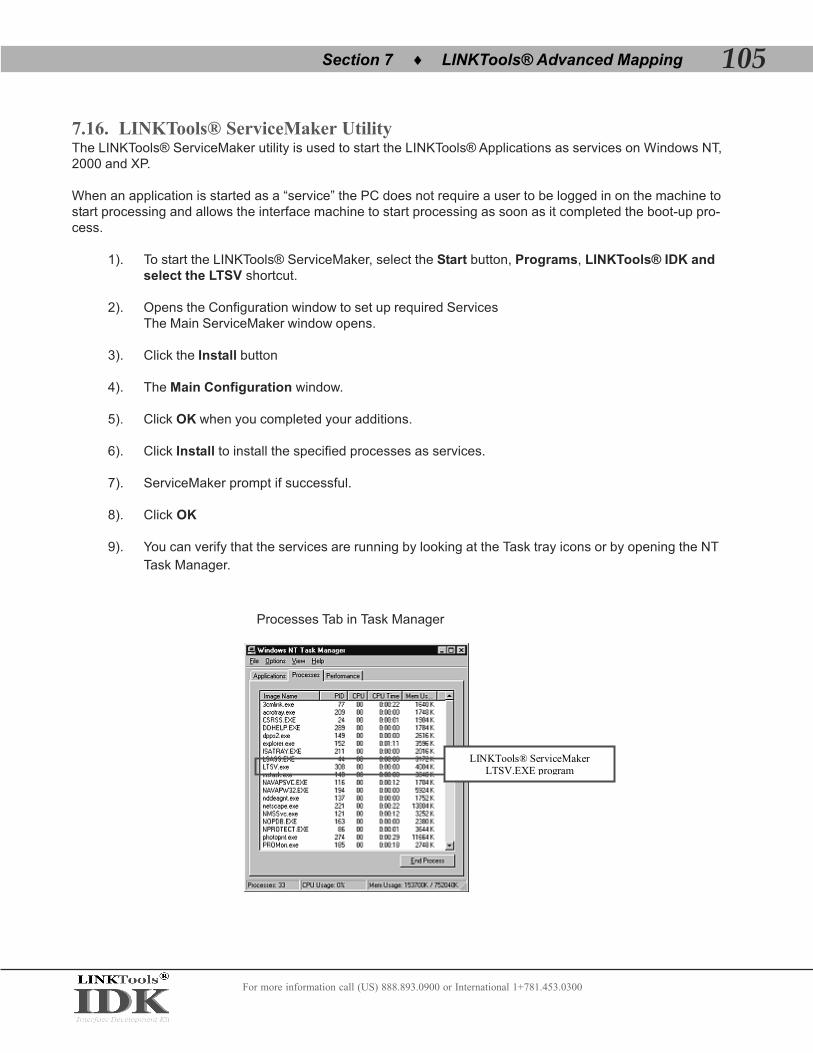
For more information call (US) 888.893.0900 or International 1+781.453.0300
7.16. LINKTools® ServiceMaker UtilityThe LINKTools® ServiceMaker utility is used to start the LINKTools® Applications as services on Windows NT,2000 and XP.
When an application is started as a “service” the PC does not require a user to be logged in on the machine tostart processing and allows the interface machine to start processing as soon as it completed the boot-up pro-cess.
1). To start the LINKTools® ServiceMaker, select the Start button, Programs, LINKTools® IDK andselect the LTSV shortcut.
2). Opens the Configuration window to set up required ServicesThe Main ServiceMaker window opens.
3). Click the Install button
4). The Main Configuration window.
5). Click OK when you completed your additions.
6). Click Install to install the specified processes as services.
7). ServiceMaker prompt if successful.
8). Click OK
9). You can verify that the services are running by looking at the Task tray icons or by opening the NT
Task Manager.
LINKTools® ServiceMaker LTSV.EXE program
Processes Tab in Task Manager
105♦Section 7 LINKTools® Advanced Mapping

For more information call (US) 888.893.0900 or International 1+781.453.0300
7.17. LINKTools® and HL7 Interface Design
i. HL7 Message Construction Rules
Note: These message construction rules define the standard HL7 encoding rules, creating variable length delim-
ited messages. Although only one set of encoding rules is defined as a standard in HL7 Version 2.3, other encod-
ing rules are possible (but since they are non-standard, they may only be used by a site-specific agreement).
Step 1: Construct the segments in the order defined for the message. Each message is constructed as follows:
A). The first three characters are the segment ID code
B). Each data field in sequence is inserted in the segment in the following manner:
1). A field separator is placed in the segment
2). If the value is not present, no further characters are required
3). If the value is present, but null, the characters “” (two consecutive double quotation marks) areplaced in the field
4). Otherwise, place the characters of the value in the segment. As many characters can beincluded as the maximum defined for the data field. It is not necessary, and is undesirable, topad fields to fixed lengths. Padding to fixed lengths is permitted.
5). If the field definition calls for a field to be broken into components, the following rules are used:
a). If more than one component is included they are separated by the component separator (^)
b). Components that are present but null are represented by the characters “”
c). Components that are not present are treated by including no characters in the component
c). Components that are not present at the end of a field need not be represented by compo-nent separators. For example, the two data fields are equivalent:
|ABC^DEF^^| and |ABC^DEF|
6). If the component definition calls for a component to be broken into subcomponents, thefollowing rules are used:
a). If more than one subcomponent is included they are separated by the subcomponentseparator
b). Subcomponents that are present but null are represented by the characters “”
c). Subcomponents that are not present are treated by including no characters in the subcom-ponent
d). Subcomponents that are not present at the end of a component need not be representedby subcomponent separators. For example, the two data components are equivalent:
^XXX&YYY&&^ and ^XXX&YYY^
106 Section 7 LINKTools® Advanced Mapping♦

For more information call (US) 888.893.0900 or International 1+781.453.0300
Web: www.linkmed.com
7). If the field definition permits repetition of a field, the following rules are used, the repetitionseparator is used only if more than one occurrence is transmitted and is placed between occur-rences. (If three occurrences are transmitted, two repetition separators are used.) In the ex-ample below, two occurrences of telephone number are being sent:
|234-7120~599-1288B1234|
c). Repeat Step 1b while there are any fields present to be sent. If all the data fields remainingin the segment definition are not present there is no requirement to include any moredelimiters.
d). End each segment with an ASCII carriage return character
Step 2: Repeat Step 1 until all segments has been generated.
The following rules apply to receiving HL7 messages and converting their contents to data values:
a). Ignore segments, fields, components, subcomponents, and extra repetitions of a field that arepresent but were not expected.
b). Treat segments that were expected but are not present as consisting entirely of fields that arenot present.
c). Treat fields and components that are expected but were not included in a segment as notpresent.
ii. Planning Your HL7 interface
*** The LINKTools® Interface Engine processes message based on instruction in the Mapper Templates, it is veryimportant that you know how to configure the Mapper Template using the LINKTools® Dynamic Mapper Applica-tion. ***
107♦Section 7 LINKTools® Advanced Mapping

For more information call (US) 888.893.0900 or International 1+781.453.0300
Web: www.linkmed.com
XX. Troubleshooting
8.0. HL7 TCP/IP Receiver and Transmitter
My TCP/IP Receiver has no connection?
Make sure the machine port numbers to receive the HL7 order message is correctly set. The sendingsystem should give you port numbers information prior to sending HL7 Order messages. Open theTCP/IP Receiver by [Click] on the “Receiver” shortcut icon from your desk top then [Click] on the“Option” icon to access the Receiver configuration screen.
My TCP/IP Receiver has connection but did not send HL7 Acknowledgment to the SendingSystem?
This happened when the receiver is not configured to automatically send an HL7 Acknowledgment. Toconfigure the Receiver to send an HL7 Acknowledgment you must know 2 HL7 order messageelements:
1. The Message Type ID located on MSH_11_1 (P, T or D)2. The HL7 Order message version number MSH_12_1 (2.1, 2.2, 2.3 or 2.4)
108 Section 8 LINKTools® Troubleshooting♦
Make sure the port# is correctly set to the sending system requirement
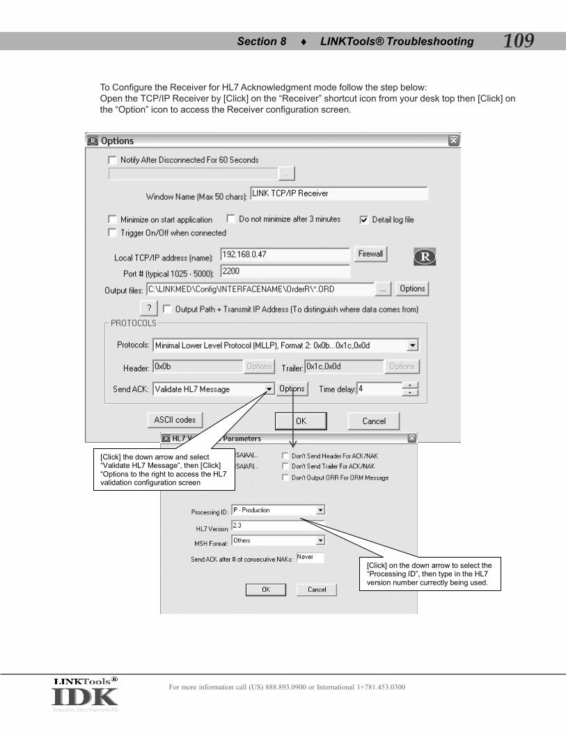
To Configure the Receiver for HL7 Acknowledgment mode follow the step below:Open the TCP/IP Receiver by [Click] on the “Receiver” shortcut icon from your desk top then [Click] onthe “Option” icon to access the Receiver configuration screen.
For more information call (US) 888.893.0900 or International 1+781.453.0300
109♦Section 8 LINKTools® Troubleshooting
[Click] on the down arrow to select the “Processing ID”, then type in the HL7 version number currectly being used.
[Click] the down arrow and select “Validate HL7 Message”, then [Click] “Options to the right to access the HL7 validation configuration screen

How do I configure detail log files on the TCP/IP Receiver and Transmitter?
To have a detail log files from the Receiver you must first enable this feature in the receiver configura-tion by [click] on the check box next to “Detail Log file”, then send the HL7 Order message through.The detail log file is kept by the Receiver in plain text format that include the following information inthe” Archive!” folder inside “OrderLNK” interface folder:
1. Date and time the Receiver is turn on or off.2. Socket level connection to what IP address.3. Fail safe of the network connection used by the Receiver.4. Detail message and date/time it is receive by the Receiver.5. Acknowledgment sent to the sending system by the Receiver.6. Error Message sent to the sending system by the Receiver.
To access the Receiver “Detail log file” [Right-Click] on the Windows® Start button select” Explorethen browse to OrderLNK interface folder. Look for “Archive!” folder double click to open. The“Archive!” folder may contain several more sub folders, [Click] open the “Receive!” folder to access thelog file.
What does Display Menu Option do on both the TCP/IP Receiver and Transmitter?
The display menu option allows user to see the content of the transmitted or received messagedisplayed on the Transmitter or Receiver screen. The message is scrolling up as new one beingreceived or transmitted, the Pause for 60 seconds allows user to view the message in stationary modefor 60 seconds. This feature is not stopping the transmitter or receiver from sending or receiving newmessages on the background only allows user to see a particular record displayed on screen.
For more information call (US) 888.893.0900 or International 1+781.453.0300
110 Section 8 LINKTools® Troubleshooting♦
Pause 60 Seconds allows stationarydisplay of transmitted or received messages pause for 60 seconds for troubleshooting purpose

What does Trigger On/Off when connected do if the connection is down? Can you make itsend a page or e-mail if the link is down? What does this do if the host connects only if it hasdata?
The trigger on and off is designed for trouble shooting a connection between user system and thesending system. The triggering mechanism is to look for signal that the network is not down but thetransmitter is shutting down when it has no file to send, this process is run in the back ground. Thereceiver currently has no mechanism to send an email or page if the connection is lost; however thereis an X mark to alert the system admin that there is no connection between the Receiver and Sender.If the sending system disconnect when there is no file to send the receiver will also have an X mark,the triggering mechanism if checked will check the connection every 10 second. For good practice isto leave the Receiver on at all time and checked the trigger on and off when connected only if thenetwork is not stable.
For more information call (US) 888.893.0900 or International 1+781.453.0300
111♦Section 8 LINKTools® Troubleshooting
Check this option only for troubleshooting the network connection between the Receiver and the Sending System (HIS)

My TCP/IP Receiver has connection but did not keep the file being sent from the HIS?
This is due to the Receiver rejecting the message. Check to make sure that the HL7 Validation andprotocols are correctly configured. Check the Header and Trailer of the message being sent somesystems used custom Header and Trailer to send their HL7 message.
My Transmitter keep sending the same message over and over, which cause messages tobackup in the folder?
The Transmitter is configured to expect a standard HL7 Acknowledgment from the receiving systemafter the message it is sending is received; however some system only send an Acknowledgment for avalid HL7 message only after it read through the message and determine that it is a valid HL7 mes-sage, for some reason that system can not be configured to send the NAK (Error) message if it foundan invalid HL7 message. To fix this particular problem configure the TCP/IP Transmitter to move thebad message to the “CantSend” folder after X number of try. The “CantSend” Folder is automaticallycreated in the same folder where the message is being pickup and send.
For more information call (US) 888.893.0900 or International 1+781.453.0300
112 Section 8 LINKTools® Troubleshooting♦
Type in the number of try before moving the corrupted message to a “CantSend” folder