get more information by downloading chroma ate solutions …
TRANSCRIPT


Get more information by downloading Chroma ATE Solutions APP

Implementation of IEC 61000-4-17 DC Ripple Immunity Test Standard
with Chroma 61509 Programmable AC Source
Version 1.1 June 2020
CHROMA ATE INC. All Rights Reserved

ii
Legal Notices The information in this document is subject to change without notice. Chroma ATE INC. makes no warranty of any kind with regard to this document, including, but not limited to, the implied warranties of merchantability and fitness for a particular purpose. Chroma ATE INC. shall not be held liable for errors contained herein or direct, indirect, special, incidental or consequential damages in connection with the furnishing, performance, or use of this material. CHROMA ATE INC. 66 Huaya 1st Road, Guishan, Taoyuan 33383, Taiwan Copyright Notices. Copyright 2020 Chroma ATE INC., all rights reserved. Reproduction, adaptation, or translation of this document without prior written permission is prohibited, except as allowed under the copyright laws.

ATE Inc.
iii
Table of Contents 1. Document Contents ......................................................................................... 1
2. Introduction to IEC 61000-4-17 Standard........................................................ 2 Summary ........................................................................................................... 2 2.1 Purpose ............................................................................................................. 2 2.2 Test Conditions .................................................................................................. 2 2.3
Test Level ................................................................................................... 2 2.3.1 Test Frequency .......................................................................................... 2 2.3.2 Test Waveform ........................................................................................... 3 2.3.3
3. 48V DC Ripple Tests ........................................................................................ 4 Purpose ............................................................................................................. 4 3.1 Introduction of Test Instrument ........................................................................... 4 3.2 Test Items .......................................................................................................... 4 3.3
Test 1: 1-Phase Rectified Waveform (50Hz) ............................................... 5 3.3.1 Test 2: 1-Phase Rectified Waveform (300Hz) ............................................. 8 3.3.2 Test 3: 3-Phase Rectified Waveform (50Hz) ..............................................11 3.3.3 Test 4: 3-Phase Rectified Waveform (300Hz) ............................................14 3.3.4


ATE Inc.
1
1. Document Contents This document includes the specification of IEC 61000-4-17 DC ripple immunity test standard and waveform related parameter calculations along with the operation process, test items and test waveform for performing 48V DC ripple immunity tests on Chroma 61509 Programmable AC Source.
ATE Inc.
2
2. Introduction to IEC 61000-4-17 Standard
Summary 2.1This standard defines the method for testing DC input immunity on the input ports of electrical appliances or electronic equipment. The related fields of application are: appliances that provide DC power from the rectifier system, and batteries that are being charged.
Purpose 2.2The purpose of the standard is to build a common and repeatable test basis to be applied in the laboratory or to the electrical and electronic equipment, simulating the environment when subjected to ripple voltage.
Test Conditions 2.3
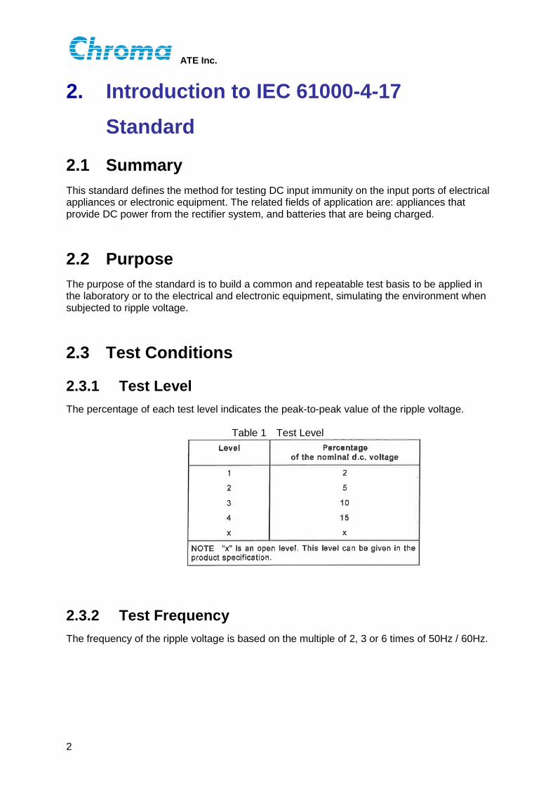
Test Level 2.3.1The percentage of each test level indicates the peak-to-peak value of the ripple voltage.
Table 1 Test Level
Test Frequency 2.3.2The frequency of the ripple voltage is based on the multiple of 2, 3 or 6 times of 50Hz / 60Hz.

ATE Inc.
3
Test Waveform 2.3.3It defines the ripple test waveform based on the charge/discharge characteristics of rectified system with filter capacitor for single and three phase power system.
Figure 1 1-Phase Rectified Test Waveform
Figure 2 3-Phase Rectified Test Waveform

ATE Inc.
4
3. 48V DC Ripple Tests
Purpose 3.1The 48V DC ripple test is going to simulate the specific waveform which defined in IEC 61000-4-17 by using 61509 programmable AC source as test instrument. User can use these specific output waveforms to test the ripple immunity of the DUT.
Introduction of Test Instrument 3.2Table 2 Chroma 61509 Programmable AC Source Specifications
Test Items 3.3The test items are set by adding 50Hz or 300Hz to 48VDC on the 1-phase or 3-phase rectified waveforms with 15% amplitude (level 4) ripples.

ATE Inc.
5
Table 3 IEC 61000-4-17 Standard Test Items
The test will use the Sequence 0 and Sequence 1 of LIST mode advanced programming function of 61509 programmable AC source to simulate the ripple waveform occurred with the charging and discharging of the filter capacitor. And repeat these sequences continuously to simulate the ripple test waveform defined by the standard.
Test 1: 1-Phase Rectified Waveform (50Hz) 3.3.11. Parameter calculation schematic
Figure 3 1-Phase Rectified Waveform (50Hz) –Parameter Calculation Schematic (voltage,
phase angle, time) 2. Sequence 0 charging parameter calculation
A. Ripple voltage RMS value
The peak value of ripple is the base voltage 48V plus 15% amplitude = 51.6V. And let 51.6V divided by√2 to get the ripple voltage RMS value = 36.5Vac.
B. Ripple frequency
Test 1 frequency is 50Hz.

ATE Inc.
6
C. Starting phase angle of ripple
The start value of ripple is the base voltage 48V minus 15% amplitude = 44.4V. Use sine wave formula to calculate the starting phase angle θ.
V(t) = Vpeak × Sinθ; 44. 4 = 51.6 × Sinθ; θ = 59.36°
D. The charging duration time
Sequence 0 is to simulate the ripple caused by capacitor in charging. Use sine wave formula to calculate the starting time t1.
V(t) = Vpeak × Sinθ = Vpeak × Sin(2πft);
Sin(2πft) =𝑉(𝑡)𝑉𝑉𝑉𝑉𝑉
;
t1 =1
2𝜋𝜋sin−1
𝑉(𝑡)𝑉𝑉𝑉𝑉𝑉
=𝑇
2𝜋sin−1
44.451.6
= 20 ×59.36°360°
= 3.29 ms
The charging is end at the one quarter of period = 14
× 20 = 5𝑚𝑚. So we can get the Sequence 0 duration time = 5 – 3.29 = 1.71ms.
E. Chroma 61509 List Mode operation menu
Figure 4 1-Phase Rectified Waveform (50Hz) - Sequence0 Edit Menu
3. Sequence 1 discharging parameter calculation
A. Discharging voltage
The charging starting voltage is the peak value of ripple = 51.6V. The ending voltage is equal to the start value of charging = 44.4V.
B. The discharging duration time
The discharging is end at t2 = 𝑇2
+ t1 = 202
+ 3.29 = 13.29𝑚𝑚. So we get the
Sequence 1 duration time = t2 − 𝑇4
= 13.29− 5 = 8.29𝑚𝑚.
C. Chroma 61509 List Mode operation menu

ATE Inc.
7
Figure 5 1-Phase Rectified Waveform (50Hz) – Sequence1 Edit Menu
4. Actual waveform
A. Charging waveform
Charging from 44.4V to 51.6V, and the charging time is approximately 1.71ms. Meet the definition of ripple waveform in the standard.
Figure 6 1-Phase Rectified Waveform (50Hz) – Actual Charging Waveform
B. Discharging waveform
Discharging from 51.6V to 44.4V, and the discharging time is approximately 8.29ms. Meet the definition of ripple waveform in the standard.
Figure 7 1-Phase Rectified Waveform (50Hz) – Actual Discharging Waveform
ATE Inc.
8
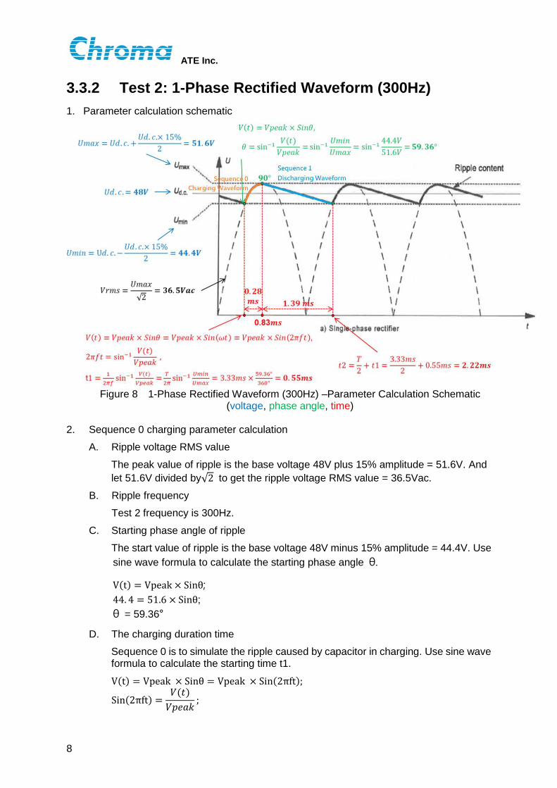
Test 2: 1-Phase Rectified Waveform (300Hz) 3.3.21. Parameter calculation schematic
Figure 8 1-Phase Rectified Waveform (300Hz) –Parameter Calculation Schematic
(voltage, phase angle, time) 2. Sequence 0 charging parameter calculation
A. Ripple voltage RMS value
The peak value of ripple is the base voltage 48V plus 15% amplitude = 51.6V. And let 51.6V divided by√2 to get the ripple voltage RMS value = 36.5Vac.
B. Ripple frequency
Test 2 frequency is 300Hz.
C. Starting phase angle of ripple
The start value of ripple is the base voltage 48V minus 15% amplitude = 44.4V. Use sine wave formula to calculate the starting phase angle θ.
V(t) = Vpeak × Sinθ; 44. 4 = 51.6 × Sinθ; θ = 59.36°
D. The charging duration time
Sequence 0 is to simulate the ripple caused by capacitor in charging. Use sine wave formula to calculate the starting time t1.
V(t) = Vpeak × Sinθ = Vpeak × Sin(2πft);
Sin(2πft) =𝑉(𝑡)𝑉𝑉𝑉𝑉𝑉
;

ATE Inc.
9
t1 =1
2𝜋𝜋sin−1
𝑉(𝑡)𝑉𝑉𝑉𝑉𝑉
=𝑇
2𝜋sin−1
44.451.6
= 3.33 ×59.36°360°
= 0.55 ms
The charging is end at the one quarter of period = 14
× 3.33 = 0.83𝑚𝑚. So we can get the Sequence 0 duration time = 0.83 – 0.55 = 0.28ms.
E. Chroma 61509 List Mode operation menu
Figure 9 1-Phase Rectified Waveform (300Hz) - Sequence0 Edit Menu
3. Sequence 1 discharging parameter calculation
A. Discharging voltage
The charging starting voltage is the peak value of ripple = 51.6V. The ending voltage is equal to the start value of charging = 44.4V.
B. The discharging duration time
The discharging is end at t2 = 𝑇2
+ t1 = 3.332
+ 0.55 = 2.22𝑚𝑚. So we get the
Sequence 1 duration time = t2 − 𝑇4
= 2.22− 0.83 = 1.39𝑚𝑚.
C. Chroma 61509 List Mode operation menu
Figure 10 1-Phase Rectified Waveform (300Hz) – Sequence1 Edit Menu

ATE Inc.
10
4. Actual waveform
A. Charging waveform
Charging from 44.4V to 51.6V, and the charging time is approximately 0.28ms. Meet the definition of ripple waveform in the standard.
Figure 11 1-Phase Rectified Waveform (300Hz) – Actual Charging Waveform
B. Discharging waveform
Discharging from 51.6V to 44.4V, and the discharging time is approximately 1.39ms. Meet the definition of ripple waveform in the standard.
Figure 12 1-Phase Rectified Waveform (300Hz) – Actual Discharging Waveform
ATE Inc.
11
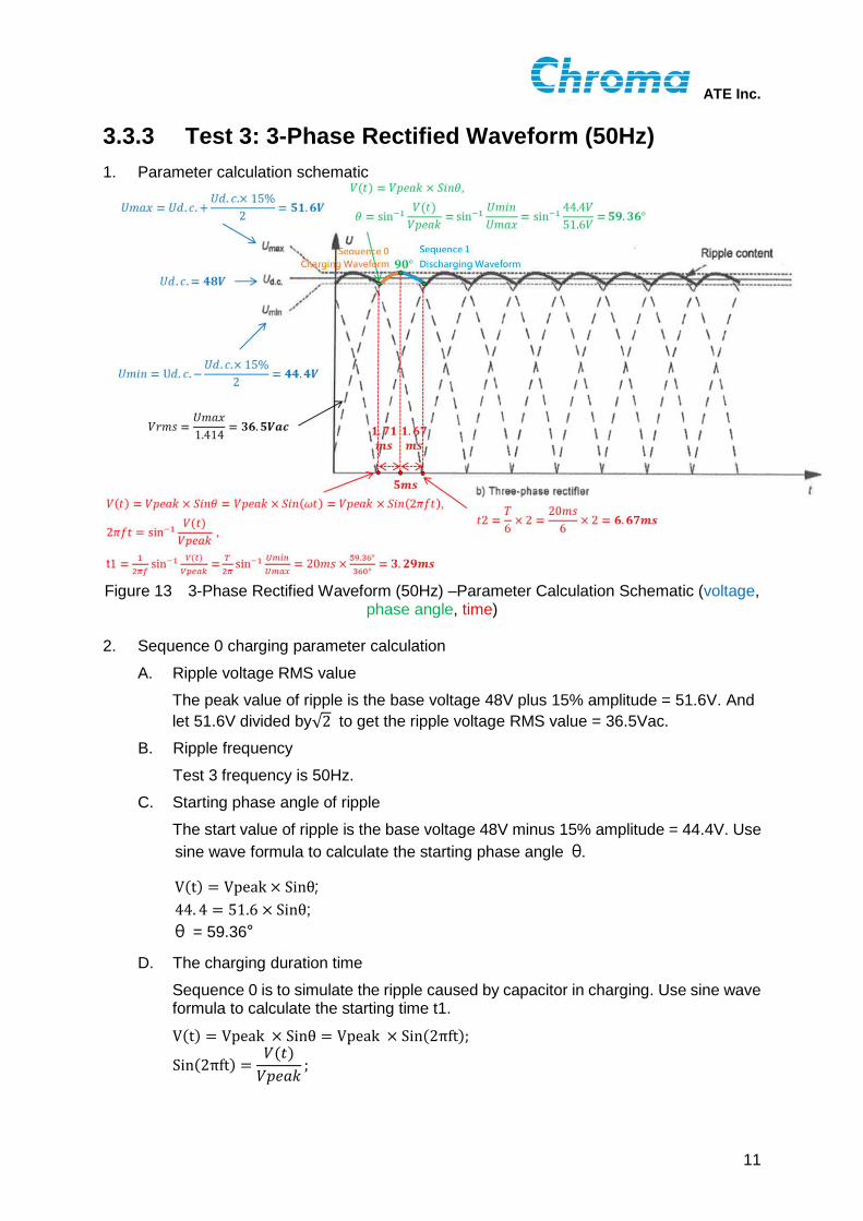
Test 3: 3-Phase Rectified Waveform (50Hz) 3.3.31. Parameter calculation schematic
Figure 13 3-Phase Rectified Waveform (50Hz) –Parameter Calculation Schematic (voltage,
phase angle, time) 2. Sequence 0 charging parameter calculation
A. Ripple voltage RMS value
The peak value of ripple is the base voltage 48V plus 15% amplitude = 51.6V. And let 51.6V divided by√2 to get the ripple voltage RMS value = 36.5Vac.
B. Ripple frequency
Test 3 frequency is 50Hz.
C. Starting phase angle of ripple
The start value of ripple is the base voltage 48V minus 15% amplitude = 44.4V. Use sine wave formula to calculate the starting phase angle θ.
V(t) = Vpeak × Sinθ; 44. 4 = 51.6 × Sinθ; θ = 59.36°
D. The charging duration time
Sequence 0 is to simulate the ripple caused by capacitor in charging. Use sine wave formula to calculate the starting time t1.
V(t) = Vpeak × Sinθ = Vpeak × Sin(2πft);
Sin(2πft) =𝑉(𝑡)𝑉𝑉𝑉𝑉𝑉
;

ATE Inc.
12
t1 =1
2𝜋𝜋sin−1
𝑉(𝑡)𝑉𝑉𝑉𝑉𝑉
=𝑇
2𝜋sin−1
44.451.6
= 20 ×59.36°360°
= 3.29 ms
The charging is end at the one quarter of period = 14
× 20 = 5𝑚𝑚. So we can get the Sequence 0 duration time = 5 – 3.29 = 1.71ms.
E. Chroma 61509 List Mode operation menu
Figure 14 3-Phase Rectified Waveform (50Hz) - Sequence0 Edit Menu
3. Sequence 1 discharging parameter calculation
A. Discharging voltage
The charging starting voltage is the peak value of ripple = 51.6V. The ending voltage is equal to the start value of charging = 44.4V.
B. The discharging duration time
Take 3-phase rectified waveform diagram from standard for reference, and the discharging is end at the second one-sixth period point= 𝑇
6× 2 = 20
6× 2 = 6.67𝑚𝑚.
So we get the Sequence 1 duration time = t2 − 𝑇4
= 6.67 − 5 = 1.67𝑚𝑚.
C. Chroma 61509 List Mode operation menu
Figure 15 3-Phase Rectified Waveform (50Hz) – Sequence1 Edit Menu
4. Actual waveform
A. Charging waveform
Charging from 44.4V to 51.6V, and the charging time is approximately 1.71ms. Meet the definition of ripple waveform in the standard.

ATE Inc.
13
Figure 16 3-Phase Rectified Waveform (50Hz) – Actual Charging Waveform
B. Discharging waveform
Discharging from 51.6V to 44.4V, and the discharging time is approximately 1.67ms. Meet the definition of ripple waveform in the standard.
Figure 17 3-Phase Rectified Waveform (50Hz) – Actual Discharging Waveform

ATE Inc.
14
Test 4: 3-Phase Rectified Waveform (300Hz) 3.3.41. Parameter calculation schematic
Figure 18 3-Phase Rectified Waveform (300Hz) –Parameter Calculation Schematic (voltage,
phase angle, time) 2. Sequence 0 charging parameter calculation
A. Ripple voltage RMS value
The peak value of ripple is the base voltage 48V plus 15% amplitude = 51.6V. And let 51.6V divided by√2 to get the ripple voltage RMS value = 36.5Vac.
B. Ripple frequency
Test 4 frequency is 300Hz.
C. Starting phase angle of ripple
The start value of ripple is the base voltage 48V minus 15% amplitude = 44.4V. Use sine wave formula to calculate the starting phase angle θ.
V(t) = Vpeak × Sinθ; 44. 4 = 51.6 × Sinθ; θ = 59.36°
D. The charging duration time
Sequence 0 is to simulate the ripple caused by capacitor in charging. Use sine wave formula to calculate the starting time t1.
V(t) = Vpeak × Sinθ = Vpeak × Sin(2πft);
Sin(2πft) =𝑉(𝑡)𝑉𝑉𝑉𝑉𝑉
;

ATE Inc.
15
t1 =1
2𝜋𝜋sin−1
𝑉(𝑡)𝑉𝑉𝑉𝑉𝑉
=𝑇
2𝜋sin−1
44.451.6
= 3.33 ×59.36°360°
= 0.55 ms
The charging is end at the one quarter of period = 14
× 3.33 = 0.83𝑚𝑚. So we can get the Sequence 0 duration time = 0.83 – 0.55 = 0.28ms.
E. Chroma 61509 List Mode operation menu
Figure 19 3-Phase Rectified Waveform (300Hz) - Sequence0 Edit Menu
3. Sequence 1 discharging parameter calculation
A. Discharging voltage
The charging starting voltage is the peak value of ripple = 51.6V. The ending voltage is equal to the start value of charging = 44.4V.
B. The discharging duration time
Take 3-phase rectified waveform diagram from standard for reference, and the discharging is end at the second one-sixth period point= 𝑇
6× 2 = 3.33
6× 2 = 1.11𝑚𝑚.
So we get the Sequence 1 duration time = t2 − 𝑇4
= 1.11 − 0.83 = 0.28𝑚𝑚.
C. Chroma 61509 List Mode operation menu
Figure 20 3-Phase Rectified Waveform (300Hz) – Sequence1 Edit Menu

ATE Inc.
16
4. Actual waveform
A. Charging waveform
Charging from 44.4V to 51.6V, and the charging time is approximately 0.28ms. Meet the definition of ripple waveform in the standard.
Figure 21 3-Phase Rectified Waveform (300Hz) – Actual Charging Waveform
B. Discharging waveform
Discharging from 51.6V to 44.4V, and the discharging time is approximately 0.28ms. Meet the definition of ripple waveform in the standard.
Figure 22 3-Phase Rectified Waveform (300Hz) – Actual Discharging Waveform


CHROMA ATE INC.
致茂電子股份有限公司
66 Huaya 1st Road, Guishan,
Taoyuan 33383, Taiwan
台灣桃園市 33383龜山區
華亞一路 66號
T +886-3-327-9999
F +886-3-327-8898
Mail: [email protected]
http://www.chromaate.com
Copyright by CHROMA ATE INC. All Rights Reserved. All other trade names referenced are the properties of their respective companies.