gesture based home automation for the physically disabled
TRANSCRIPT

University of Arkansas, FayettevilleScholarWorks@UARK
Theses and Dissertations
5-2013
Gesture Based Home Automation for thePhysically DisabledAlexander Hugh NelsonUniversity of Arkansas, Fayetteville
Follow this and additional works at: http://scholarworks.uark.edu/etd
Part of the Other Computer Engineering Commons, and the Other Computer SciencesCommons
This Thesis is brought to you for free and open access by ScholarWorks@UARK. It has been accepted for inclusion in Theses and Dissertations by anauthorized administrator of ScholarWorks@UARK. For more information, please contact [email protected], [email protected].
Recommended CitationNelson, Alexander Hugh, "Gesture Based Home Automation for the Physically Disabled" (2013). Theses and Dissertations. 720.http://scholarworks.uark.edu/etd/720

GESTURE BASED HOME AUTOMATION FOR THE PHYSICALLY DISABLED

GESTURE BASED HOME AUTOMATION FOR THE PHYSICALLY DISABLED
A thesis submitted in partial fulfillment of the requirements for the degree of
Master of Science in Computer Engineering
By
Alexander H. Nelson University of Arkansas
Bachelor of Science in Computer Engineering, 2012
May 2013 University of Arkansas

ABSTRACT
Paralysis and motor-impairments can greatly reduce the autonomy and quality of life of a
patient while presenting a major recurring cost in home-healthcare. Augmented with a non-
invasive wearable sensor system and home-automation equipment, the patient can regain a level
of autonomy at a fraction of the cost of home nurses. A system which utilizes sensor fusion, low-
power digital components, and smartphone cellular capabilities can extend the usefulness of such
a system to allow greater adaptivity for patients with various needs. This thesis develops such a
system as a Bluetooth enabled glove device which communicates with a remote web server to
control smart-devices within the home. The power consumption of the system is considered as a
major component to allow the system to operate while requiring little maintenance, allowing for
greater patient autonomy. The system is evaluated in terms of power consumption and accuracy
to prove its viability as a home accessibility tool.

This thesis is approved for recommendation
to the Graduate Council.
Thesis Director:
____________________________________
Dr. James Patrick Parkerson
Thesis Committee:
____________________________________
Dr. Nilanjan Banerjee (ex officio)
____________________________________
Dr. Craig Thompson

THESIS DUPLICATION RELEASE
I hereby authorize the University of Arkansas Libraries to duplicate this thesis when needed for
research and/or scholarship.
Agreed ________________________________________
Alexander H. Nelson
Refused ________________________________________

ACKNOWLEDGEMENTS
I thank Dr. James Patrick Parkerson and Dr. Nilanjan Banerjee for directing and funding
this research in HCI. Their knowledge, expertise, and leadership guided me to the completion of
this thesis. I would also like to thank Dr. Craig Thompson as the third member of my thesis
committee, who provided excellent feedback and guidance in the construction of the written
components of this thesis.
I would like to thank Jack Schmandt for his hardware support in the construction of the
power management and solar circuits as well as support for a revamped headband sensor. I
would like to thank William Wilkins for his systems support building the Smartphone
applications and assistance with the Bluetooth communications.
I also thank my wife for her patience and support during this year-long endeavor, helping
me to remain sane when various components refused to funciton no matter what I tried. I would
also like to thank my parents who have provided for me and encouraged my continued pursuit of
education for these many years.

TABLE OF CONTENTS
1. Introduction ...............................................................................................................................1
1.1 Background and Problem ..................................................................................................... 1
1.2 Objective .............................................................................................................................. 2
1.3 Approach .............................................................................................................................. 3
1.4 Organization of this Thesis .................................................................................................. 3
2. Background ...............................................................................................................................4
2.1 Key Concepts ....................................................................................................................... 4
2.1.1 Computational Gesture Recognition ............................................................................. 4
2.1.2 Micro-Harvesting .......................................................................................................... 4
2.1.3 Sensor System Development ........................................................................................ 5
2.2 Related Work ....................................................................................................................... 5
2.2.1 Gesture Recognition...................................................................................................... 5
2.2.2 Wearable Sensors .......................................................................................................... 6
2.2.3 Renewable Energy Driven Systems .............................................................................. 7
2.2.4 Energy-Efficient Techniques ........................................................................................ 7
3. Architecture ...............................................................................................................................8
3.1 High Level Design - Hardware ............................................................................................ 8
3.2 High Level Design - Software ........................................................................................... 10
3.3 Implementation – Hardware .............................................................................................. 12
3.3.1 MSP430....................................................................................................................... 13
3.3.2 Flex Sensor Circuit ..................................................................................................... 13

3.3.3 Accelerometer ............................................................................................................. 14
3.3.4 Bluetooth Module ....................................................................................................... 14
3.3.5 Battery ......................................................................................................................... 15
3.3.6 Hardware Wake-Up Circuit ........................................................................................ 15
3.3.7 Solar Panels and Power Management System ............................................................ 17
3.4 Implementation - Algorithms............................................................................................. 18
3.4.1 Flex Gesture Detection Algorithms ............................................................................ 18
3.4.2 Accelerometer State Detection Algorithm .................................................................. 20
3.4.3 Low-Power Gesture Queuing Algorithm .................................................................... 21
4. Results and Analysis ...............................................................................................................22
4.1 Methodology ...................................................................................................................... 22
4.2 Results ................................................................................................................................ 22
4.2.1 Power Consumption .................................................................................................... 23
4.2.2 Accuracy ..................................................................................................................... 27
4.2.3 Latency ........................................................................................................................ 27
4.2.4 Program Memory ........................................................................................................ 28
4.3 Analysis ............................................................................................................................. 29
4.3.1 Use of Hardware Wake-Up Circuit in Standard Glove System .................................. 30
5. Conclusions ..............................................................................................................................32
5.1 Summary ............................................................................................................................ 32
5.2 Contributions ..................................................................................................................... 33
5.3 Future Work ....................................................................................................................... 33
References .....................................................................................................................................34

LIST OF FIGURES AND TABLES
Figure 1: Glove Device ................................................................................................................... 8
Figure 2: Abstract System Specification ......................................................................................... 9
Figure 3: Glove and Flex Circuit (Left) – Glove with Wake-Up Circuit (Right) ......................... 10
Figure 4: Standard Glove Workflow (Left) – Power Aware Glove Workflow (Right) ................ 11
Figure 5: Flex Sensor Circuit ........................................................................................................ 13
Figure 6: Orientation of ADXL345 axes ...................................................................................... 14
Figure 7: Hardware Wake-Up Circuit........................................................................................... 16
Figure 8: Solar Array and Power Management ............................................................................ 17
Figure 9: Three-Point Differencing Algorithm ............................................................................. 19
Figure 10: Hardware Wake-Up Interrupt Waveform (5-Wire)..................................................... 20
Figure 11: Power Consumption, Standard Glove System ............................................................ 24
Figure 12: Relative Power Consumption of each Device ............................................................. 24
Figure 13: Power Density of Solar Panels .................................................................................... 25
Figure 14: Power Harvested by Solar Array ................................................................................. 25
Figure 15: Power Consumption/Harvested, Power-Aware Glove ................................................ 26
Figure 16: Power Comparison of Wake-Up Circuit and ADC ..................................................... 31
Table 1: Power Micro-Benchmarks .............................................................................................. 23
Table 2: Latency Results ............................................................................................................... 28

1
1. INTRODUCTION
1.1 Background and Problem
Physical disabilities, such as paraplegia, tetraplegia, and Parkinson’s disease, can greatly
limit the autonomy of patients with respect to home living[1]. In the United States, more than
270,000 patients suffer with paralysis with some form of spinal cord injury (SCI) which
manifests itself in varied motor impairments [2]. Patients with SCI can suffer from any range of
limb mobility impairment up to complete loss of movement. Additionally, severe SCI can
culminate in the patient suffering from the loss of speech, loss of autonomous breathing,
impaired organ function, and complete loss of sensation. Patients dealing with SCI face unique
challenges performing day-to-day activities within the home and often require external help or
even a transition to an assisted living facility. According to the National Spinal Cord Injury
Statistical Center (NSCISC) approximately 86% of patients dealing with SCI are discharged to
private homes while another 6.6% are discharged to assisted living facilities [2]. The cost of
healthcare for patients dealing with SCI can create a significant economic and social burden on
the patient and their families [3]. Patients sent to assisted living facilities can spend nearly
$177,000 per year in healthcare costs alone [4]. Many of the patients sent to private homes
cannot live autonomously and require a caretaker (home nurse or family member) to assist the
patient with various tasks throughout the home.
Computational gesture recognition is a field which has made significant technological
advancement in the past few years. Techniques have been developed which use gesture
recognition to assist patients with disabilities using systems including electrooculograph (EOG)
sensors [5], gaming peripherals [6], and camera-based eye tracking [7] among other forms of

2
gesture input. These systems usually suffer from limitations with respect to their applicability to
physical disabilities. First, the system may be physically intrusive as is the case with most human
computer interaction (HCI) solutions. Second, these systems are generally expensive and require
considerable external hardware in order to derive the gestures. Third, the systems generally
assume a larger limb mobility range or accuracy than what may be provided by various physical
disabilities. Finally, while these systems may exist as standalone gesture recognition sensors,
systems which utilize gesture input as an end-to-end cyber-physical application are scarce.
Micro-harvesting from sources such as indoor light can enable a plethora of self-
sustainable systems. This includes healthcare systems [5] and indoor home monitoring systems
[8]. Self-sustainability is especially important in wearable devices for individuals with cognitive
and physical impairments as any needed system maintenance reduces the effectiveness of such a
system drastically. A wearable sensor that could operate perpetually from the energy gathered
from indoor scavenged light would obviate the need to change batteries, leading to a more viable
system [1] [4] [2].
1.2 Objective
This thesis presents the design, implementation, and evaluation of an end-to-end cyber-
physical home automation system for physical disabilities. The system, a data glove, utilizes
components of gesture recognition solving the issues of cost, intrusiveness, and accuracy while
providing a framework for additions to the system. The system is evaluated in terms of its power
consumption to assess the effectiveness and viability of a device which operates perpetually from
indoor micro-harvested energy.

3
1.3 Approach
In order to create the system as described, a solution is presented as a hardware/software
co-design using components of microcontroller and sensor systems, mobile development, cloud
systems, and circuit design. The system was built iteratively, utilizing concepts of the minimum
viable product followed by improvements and refinements to create an adaptive energy efficient
solution to whole home automation for disabilities.
1.4 Organization of this Thesis
Chapter 2 discusses key concepts related to this field including gesture recognition,
micro-harvesting, and senor-systems, as well as presenting a literature review of related works.
Chapter 3 provides the architecture for the entire system at hardware and software levels,
as well as the implementation details from device level to algorithmic approaches.
Chapter 4 presents empirical results of the system as functions of power consumption,
accuracy, cost, latency, and program memory. The results are discussed with respect to the field
in order to determine the impact and significance of the system as developed.
Chapter 5 summarizes the system, the results, the analysis, and concludes with the
significance of the system. Future developments and potential additions to the system are
presented and discussed.
4
2. BACKGROUND
2.1 Key Concepts
While this thesis is written so that the casual observer may understand the objective and
the overall approach, it is beneficial to full comprehension of the details for the reader to have a
working knowledge of the following topics.
2.1.1 Computational Gesture Recognition
Gesture recognition has been a significant branch of HCI dating back to the ‘Sayre’
Glove in 1977 [9]. Various gesture interpretation devices have been considered, including sensor
aided glove devices and computer vision techniques. The Microsoft Kinect is a popular recent
commercial release of a gesture recognition device, which uses depth sensors as well as high-
definition cameras to create full models of the user as an input into games. Various other
implementations have attempted to create sign-language interpretation devices as an accessibility
tool for those with vocal or aural disabilities [10]. In a broad sense, gesture recognition can be
used as another user interface (UI) peripheral (a mouse for example), with varying operational
sets depending on the hardware implementation and the software intention.
2.1.2 Micro-Harvesting
Sensor systems are often implemented as very low power devices (microwatt range), and
are therefore capable of sustaining themselves for years on a typical battery. Periodically having
to replace these sensors, however, would become a constant maintenance issue as the number of
sensors continues to expand. Micro-harvesting has been proposed as a solution to this issue by

5
providing power circuitry designed to draw power from the sensor’s surroundings to maintain
perpetual operation, and removing the maintenance as a necessary component for sensor systems
[11].
2.1.3 Sensor System Development
Sensor systems are a branch of electronics which act as data aggregators for various
sensor inputs. Systems are composed of a number of special purpose sensors and some external
communication protocol to deliver data to a consumer. The processor of the system is application
dependent, ranging from special purpose hardware meant for lowest absolute power point to
general purpose microcontrollers and even standard processors over a serial interface. The goal
of sensor systems is to model some information space numerically, the results of which are
delivered to some data consumer which can use the information for any number of purposes.
2.2 Related Work
This system builds upon previous work in gesture recognition and wearable sensor
devices as well as low power system development in order to create an end-to-end cyber-
physical home automation system. A combination of renewable energy driven systems and
energy-efficient design techniques is used to create an adaptable solution capable of long-term or
always-on technology for easier adoption within the focus demographic.
2.2.1 Gesture Recognition
Gesture recognition techniques have long been used in assistive technologies for disabled
and human computer interaction systems [6]. More specifically, hand gestures have been used as

6
a rich source of input patterns for assistive device implementations [12], including devices which
utilize pressure sensors and 3D accelerometers [13] [14] [15] [16]. Similar systems are often
computationally expensive, requiring advanced machine learning techniques in order to provide
an expanded operational set for sign language interpretation or other goals. For this system to be
useful in a day to day setting, the following features are paramount – low cost, high accuracy,
low power consumption, and unobtrusiveness. This sytem utilizes gesture recognition, building
on a large body of current work by extending its application to an always-on mobile solution to
whole home automation.
2.2.2 Wearable Sensors
Wearable sensors are widely used for health diagnostic applications. These include
electrodes for EKG, EEG, EMG, and EOG monitoring [17], vests for full body monitoring [8],
and sensors in items of day to day use such as hats and under garments [18] [19]. A primary goal
of these sensors is to detect body temperature, heart rate, brain waves, as well as pulse rate and
blood pressure [20].
Recently, there is an effort to design micro-mote platforms for health diagnostics and
wearable sensing [21]. While research efforts exist on gesture recognition, the focus on comfort
and multi-sensor gesture recognition for paralysis patients is scarce. Moreover, end-to-end cyber-
physical systems for practical applications such as home automation are few. This system fills
the gap using comfortable wearable sensors for gesture recognition. The system is used to
control home appliances for paralysis patients.

7
2.2.3 Renewable Energy Driven Systems
Most of the related work in renewable energy driven devices has focused on outdoor
solar panel driven systems. Energy harvesting systems have been developed for applications
such as tracking [22] [23], environmental sensing [24], and networking [25]. Indoor-light driven
motion sensing has been explored as a potential renewable sensing platform [26]. This body of
work extends the underlying ideas of renewable energy driven systems to ultra-low power
sustainable gesture recognition. The given system can have applications for assisted living
facilities to aid patients with various motor impairments.
This research is related to the modeling and profiling of battery-driven systems [23] [27].
Contrary to out-of-band techniques leveraged in many devices, this system uses a simple in-band
mechanism of leveraging the analog-to-digital converter as a known load to measure the voltage
drop across the batteries, therefore being able to estimate the residual battery capacity.
2.2.4 Energy-Efficient Techniques
Energy management is an important component of computing; especially in mobile,
embedded, and consumer driven systems. Energy management typically explores tradeoffs of
design parameters with respect to power consumption and performance. Classical approaches
include voltage and frequency scaling [28], turning off componenents [29] [30], and using low-
power modes on radios and other peripheral devices [31]. Recently, studies have shown that
these techniques do not remove some non-reducible power draws of the system. This has led to a
recent body of work on muli-tiered systems using hardware and software techniques for task
sharing between platforms in combination with duty cycling of higher tiers[32] [33] [34]. These
systems have been focused on medium scale sensors and PC systems.

8
3. ARCHITECTURE
The goal of this system is to apply the multi-tiered approach to always-on and renewable
energy driven devices. An application-specific hardware circuit, general purpose microcontroller,
and Bluetooth device is used to create an adaptive system that can perform gesture recognition
for home automation.
3.1 High Level Design - Hardware
The overarching system developed is an end-to-end cyper-physical system of multiple
wearable sensor inputs designed with data fusion in mind to create an accurate and widely
accessible home automation system for the physically disabled. The subsystem developed within
is a glove device which utilizes a 3D accelerometer and five flex sensors to model hand gestures.
The glove device is paired with an EOG based headband [35] to extend the accessibility to
extreme tetraplegia and Smartphone system support to expand the viability of the system beyond
the borders of the home. As such, the glove subsystem was developed with modularity in mind
and includes gesture confidence intervals to provide a platform for sensor fusion control.
Figure 1: Glove Device

9
The glove device is composed of a TI MSP430 microcontroller with various sensors as
inputs, reporting its results over a Bluetooth transceiver. These results are received by a
Smartphone which can act as a UI for controlling various menu systems or as a relay to control
specific objects. The Smartphone sends the request via Wi-Fi or its mobile connection to a
remote server which parses the request and maps it to an action. The remote server then passes
the action to the home server which controls all the smart appliances in the home [36].
Figure 2: Abstract System Specification
The power-aware glove system was developed as an extension to the original system,
utilizing similar hardware with a coprocessor interrupt circuit aimed at allowing the main system
to duty cycle during periods of in operation (Figure 3). The hardware wakeup circuit was
developed to provide a digital interrupt signal whenever any sensor inputs change significantly.
In order for the system to adapt to any light condition, the sensors and even the hardware wakeup
circuit is also duty cycled using a timer approach to allow the system to maintain an extremely
low power point, capable of storing energy from indirect indoor light

10
Figure 3: Glove and Flex Circuit (Left) – Glove with Wake-Up Circuit (Right)
3.2 High Level Design - Software
The MSP430’s were programmed using Code Composer Studio, a TI variant of the
popular Eclipse debugging platform. The code itself is written in C, with TI providing macros
and variables to easily access special purpose registers and on board peripherals. The workflow
of the two devices is shown in figure 4.

11
Figure 4: Standard Glove Workflow (Left) – Power Aware Glove Workflow (Right)
The standard glove maintains a straightforward poll and report workflow. The sensor
values are all stored on-chip until a gesture is detected based on the algorithms to be discussed in
section 3.4. To save processing power, an optional duty cycling stage can be added at the
beginning of the polling stage. During this time, any gestures performed will be ignored as each
finger is individually measured by the on-board analog-to-digital converter (ADC) and the
accelerometer must be polled on a regular basis to determine consecutive rotational positions
when looking for a turn, so it is necessary to maintain a short duty cycling period for this system.
The power-aware glove maintains two different duty cycling stages, x and y. During duty
cycle stage x, all devices are in sleep modes and any gesture input will be missed. This stage,
therefore, should be relatively small and is only included for indirect indoor light scenarios
where the power draw of the wake-up system consumes more power than the solar panels can
supply. Duty cycle stage y, however, maintains power to the flex sensors, the comparators, and
the DAC so that the interrupt signals can be sent if any threshold is broken. If no interrupt signal

12
is generated, the system will move back into a deep sleep mode and continue with the cycle. If an
interrupt signal is generated, the microcontroller wakes into active mode and determines the
correct operation to perform. The new threshold values for the DAC must then be set via a serial
interface from the microcontroller. The largest power savings from this system comes from the
Bluetooth duty cycling. Leaving the Bluetooth module on in idle mode consumes nearly an order
of magnitude more than the rest of the system combined. However, in order for the Bluetooth
system to power on, establish a connection, send a packet, and go back into sleep mode requires
5 seconds, which eliminated the possibility of a live updating UI. Therefore, gestures can be
batched based on user preference to save power on non-time critical tasks. The queuing
algorithm is discussed in greater detail in section 3.4.3.
The power aware system utilizes its on-board ADC to measure the voltage drop across
the batteries as a method for estimating the residual battery capacity, and therefore being able to
make intelligent decisions in wake-up frequency, batching, and duty cycling percentages. This
technique allows for system checkpointing if the battery capacity drops below a certain
percentage of its operating range. This serves a dual purpose of allowing requests to persist in
total system power-loss while protecting the batteries from over-discharge.
3.3 Implementation – Hardware
As shown in figure 1, the original glove device is composed of the following
components: a MSP430 microcontroller, five flex sensors, a 3D accelerometer, a Bluetooth
module, and a battery. The power aware glove extends this functionality with ten nano-power
comparators, a digital to analog converter, solar panels, and a power management circuit. Each is
explained in detail here:

13
3.3.1 MSP430
The microcontroller used for this system is a MSP430F1611. This chip has two on board
serial interfaces, an 8-port by 12-bit ADC, and 5 low power-modes. The entire system is run
from a 3.3V battery, but is tolerant between 3.7V and 2.7V. The microcontroller itself is a 16-bit
device which is capable of running at up to 8MHz, but can be scaled to reduce power
consumption.
3.3.2 Flex Sensor Circuit
The flex sensors are 4-inch long devices that act as a variable resistance. The sensors
provide 10k ohms resistance when straight, up to nearly 23k ohms when fully flexed. In order to
determine the amount that each sensor is flexed, a resistance divider is created by placing a pull-
up resistor between one terminal and VCC, with the other terminal going to GND, The contact
point for voltage detection is between the pull-down resistor and the flex sensor terminal.
Figure 5: Flex Sensor Circuit
The size of the pull-down resistance is determined by a tradeoff of two factors: power
consumption and swing voltage. A larger swing voltage allows for more accurate measurements
of the flexion, but consumes more power as can be found from the formulas P = VI and V = IR.

14
Our system uses 200k ohm pull-up resistors, allowing for voltages at the contact point between
0.187V and 0.340V with power consumption between 51.5uW and 48.8uW per sensor. The 12-
bit ADC can recognize approximately 250 different positions when using GND and the internal
2.5 reference voltage as the rails.
3.3.3 Accelerometer
The 3-D accelerometer used in the system is the ADXL345. It is capable of 10-bit
resolution at +/- 2G. Data values are requested and sent over a 3-wire SPI interface. The angle of
the accelerometer can be determined by generating the G-force values for each axis, and
performing trigonometric transformations to convert to angle between each axis. For instance,
assuming the accelerometer reports a force vector of <.0.268, 0.268, 0.464>, then the orientation
can be determined as the difference from vertical by arctan(x/z) and arctan(y/z). This would
show that the x-z angle is 30 degrees rotation positively around the y-axis, and the y-z angle is
30 degrees positively along the x-axis.
Figure 6: Orientation of ADXL345 axes
3.3.4 Bluetooth Module
The Bluetooth Module is a SPBT3632C2A.AT2, a chip that is capable of a data rate of
1.5Mbps, and can communicate over several different serial protocols. For our purposes, we

15
have gated the serial clock to 9600 so that the peripheral can be controlled by an external
32.768k Hz oscillator. The module itself exposes an API which makes connecting and
communicating with the Bluetooth stack straightforward. While a relatively low power Bluetooth
module, consuming 16.7mA current average during transmission, this chip represents the largest
power draw of the system by over an order of magnitude. Therefore, maintaining it in idle mode
(~4.9mA), sleep mode (~70uA with external oscillator), or turning the chip off is a necessity for
any effective power management. The chip will consume approximately 4.9 mA when idle.
Reducing the internal clock to 2 MHz drops the active consumption to approximately 9 mA on
average.
3.3.5 Battery
The system is powered by a 3.7V Li-ion battery rated at 1700mAh, similar to what is
found in many Smartphone devices. The battery is regulated to 3.3 V so that performance is
unaffected as the battery is drained or charged.
3.3.6 Hardware Wake-Up Circuit
The Hardware Wake-Up Circuit was designed to take advantage of the large number of
pins exposed by the MSP430, the low-power sleep modes, and its efficient wake-up times. Ten
nano-power comparators are used along with a low-power Digital-to-Analog converter (Figure
7) to create positive and negative thresholds around each individual flex sensor, which will
trigger an interrupt signal to the MSP if broken. The hardware interrupt circuit can be
implemented with each of the comparators output tied together as a single interrupt signal (1-
wire), each individual finger having its own interrupt signal (5-wire), or each individual

16
comparator having its own signal (10-wire). The advantage of maintaining more interrupt signals
is in the amount of processing required for the MSP to determine the correct operation to
perform before going back to duty-cycle mode. There is relatively little power disadvantage as
the pull-up resistors between the input and power are rather large (2.1MOhms) and the largest
power dissipation is a result of allowing the pins on the microcontroller to be driven externally.
The disadvantage of a larger number of interrupt signals is in the space required to route traces to
the microcontroller and the number of pins used on the MSP430. A full power comparison of
this system can be found in section 4.2
Figure 7: Hardware Wake-Up Circuit
This wake-up circuit can be used in place of the ADC in the standard glove system with
some design tradeoffs. These trade-offs are explored in section 4.3.
17
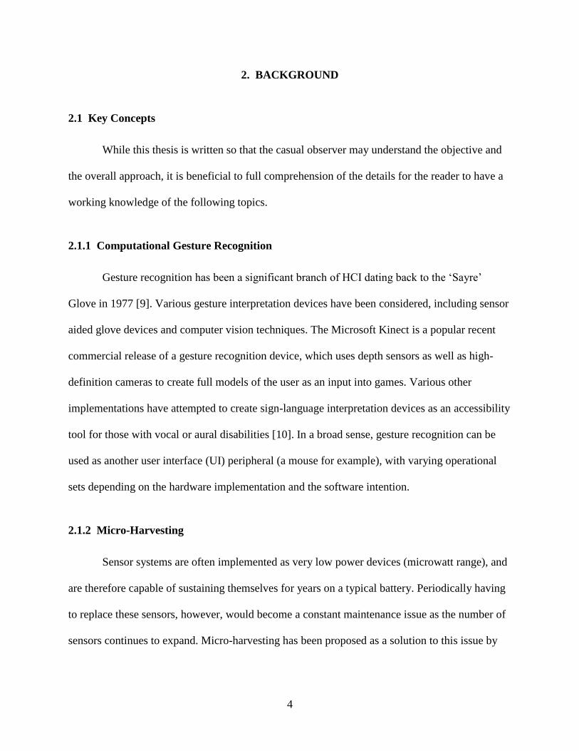
3.3.7 Solar Panels and Power Management System
The solar cells used in the power-aware system were a combination of mono-crystalline
and amorphous silicon solar cells in order to maximize energy harvesting among various light
conditions. The power management unit (PMU) is a MAX17710 IC, a special purpose chip
meant for low-power harvesting circuits with a selectable output voltage. This combination of
circuitry allows for maximum energy harvesting in changing light conditions as might be
experienced in a wearable system.
Figure 8: Solar Array and Power Management
The solar cells were profiled for power harvesting capabilities, and those results are
reported in section 4.2. The mono-crystalline solar panels were measured to be more efficient in
direct light (approximately 23 times in direct incandescent light), where the amorphous silicon
panels were more efficient in indirect or ambient light (approximately 4 times in ambient
incandescent light). The circuitry switches which panel is being harvested from based on the
output of the light sensor.

18
3.4 Implementation - Algorithms
This section discusses the gesture detection and confidence value determination in each
system as shown in Figure 4. The two systems share the same detection algorithm for the
accelerometer but use different techniques for sensing finger flexion. While related gesture
detection systems use computationally intensive neural-network approaches, this system uses
intentionally light detection algorithms capable of running in real time on the microcontroller to
prevent having to off-load data to the Smartphone which would generate large power overhead
through the Bluetooth module.
3.4.1 Flex Gesture Detection Algorithms
The standard glove uses a poll and report workflow, processing the results from each new
value to determine gestures. Values for each finger are determined by using the on-board ADC
which reports back a 12-bit integer representation of the voltage across each resistive divider.
These values are stored in an integer array of width five, and then used for comparison using a
three-point linear differencing algorithm (d(sn – sn-2) in combination with thresholds determined
by preprocessing using supervised clustering algorithms on labeled gestures.

19
Figure 9: Three-Point Differencing Algorithm
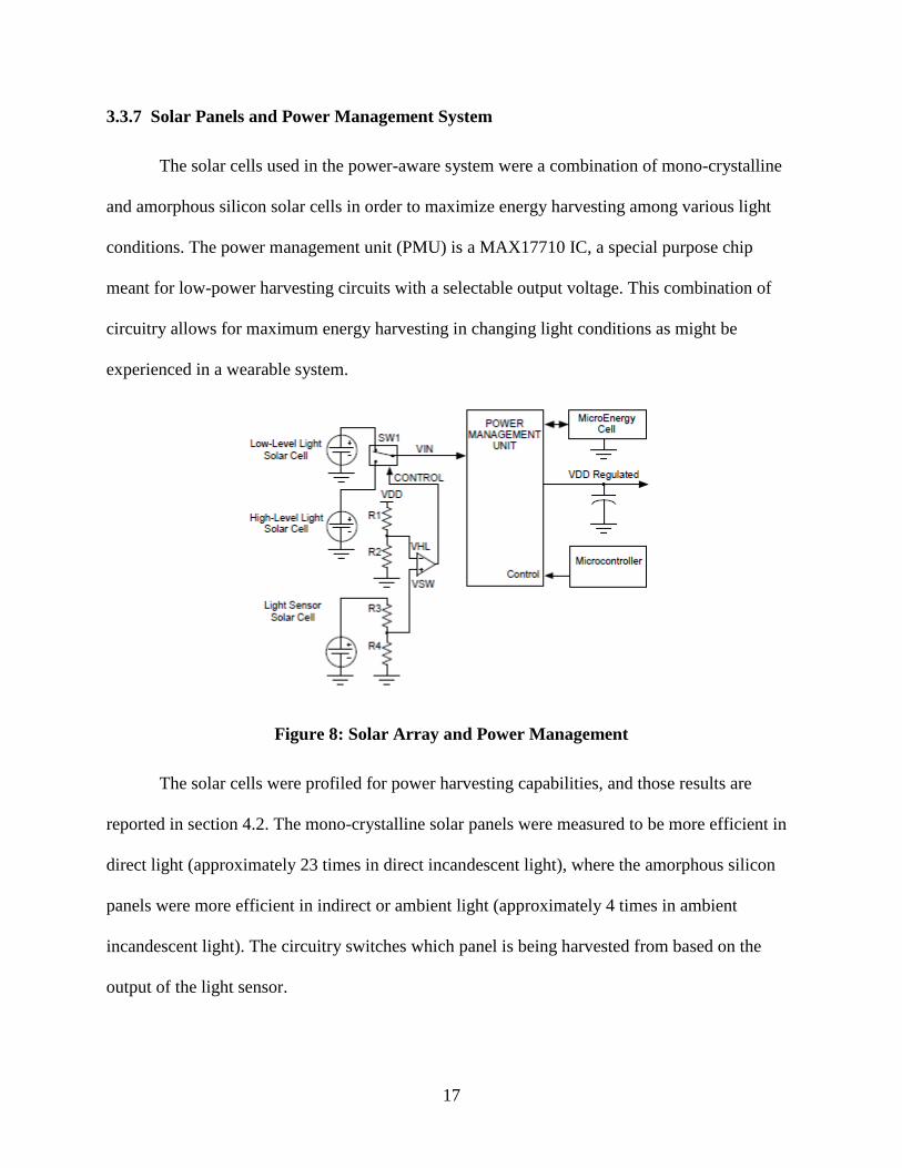
The power-aware glove uses the event driven algorithm, and therefore cannot perform a
three-point differencing algorithm as each data point is not updated until an interrupt is triggered.
Therefore, the external hardware interrupt is used to determine finger flexion. As shown in figure
10, the Wake-Up circuit will trigger an interrupt on the MSP430 when a threshold changes state.
The thresholds (VTHigh and VTLow) are adjusted to be centered around the current state of the
finger after every interrupt in order to maintain continuity when duty cycling the wake-up circuit.
Once an interrupt is triggered from one of the fingers, the system updates the current state
of the fingers, updates the thresholds presented to that finger, and then checks to see if the
current state of the system represents a gesture. At this point, an optional post-processing stage
can be implemented to increase the confidence of the gesture. This can include querying the state
of the accelerometer, requiring a mandatory “hold” time for the gesture, or measuring the exact
voltages across the dividers. Each of these options trades off power consumption and delay for
confidence in gestures. However, the consequences of a false-positive gesture is at the very least
20
an unnecessary Bluetooth packet, and could extend up to multiple compensatory Bluetooth
packets as the user attempts to correct the state of the system.
Figure 10: Hardware Wake-Up Interrupt Waveform (5-Wire)
3.4.2 Accelerometer State Detection Algorithm
The accelerometer (ADXL345) represents its orientation as a 10-bit representation of G-
Force scaled from -2G to +2G in each x, y, and z directions. Assuming the accelerometer is
experiencing very little external force, the sum of the total force experienced should be 1G
(gravity pointing in the direction of the ground). The orientation of the accelerometer can be
derived from this assumption by calculating the offset from vertical as equal to arctan(x/z) and
arctan(y/z). Precalulating these values for various angle offsets allows for simple determination

21
of approximate state (categorized into histogram like “bins”) with very little data processing on
chip.
The orientation is determined by an averaging of these predetermined bins over a variable
sized window. The confidence in that orientation is related to the variance from that orientation
over that window. For instance, if the average orientation is a 60° rotation to the right, with a
standard deviation of 10 degrees or less, we can report a high confidence that there was a turn to
the right during that window. However, if the average orientation is a 60° rotation to the right
with a standard deviation of 45 or more, then the data is noisy and will be reported with a very
low confidence interval.
3.4.3 Low-Power Gesture Queuing Algorithm
Given that the power consumption of the Bluetooth module is the largest component by
an order of magnitude, it is essential that the Bluetooth module be duty-cycled almost entirely. In
order to allow for maximal sleep time, some tasks may be queued and sent as batch operations
based on given deadlines. However, some tasks, such as turning on lights, must be performed
almost immediately in order for the system to be viable. Therefore, a set of priorities allow for
variable send times based on user-preference.
Gestures are placed into a data structure containing the gesture type, associated deadline,
and priority. Deadlines are monitored and updated as the microcontroller wakes to change duty-
cycling modes. Once a deadline for a gesture is hit, all gestures are batched by priority. The
batch operation is sent by turning on the power to the Bluetooth, initiating a connection, sending
the batch message, and then immediately shutting off power to the Bluetooth module.

22
4. RESULTS AND ANALYSIS
The two systems described are evaluated in regards to the following metrics: power
consumption, accuracy, system latency, and program size. The gesture set as defined here is a
reduced set for sensor fusion with the more limited EOG headband. This set acts as proof of
concept and can be expanded to a much larger set to individually control devices if using the
glove as a standalone system.
4.1 Methodology
In order to measure power consumption, each of the systems is measured and logged for
current using a Fluke or Agilent multimeter, which is multiplied by the voltage of the system to
achieve the power. System latency is measured using a DigiView DV-100 digital analyzer for
any processes performed on chip. The Code Composer Studio programming tool reports
compiled program size at runtime. Accuracy of the systems is measured by having external test
subjects perform a predetermined set of gestures, recording both the actions they actually
perform and the gestures reported by the system. Inaccuracies are reported both as a false-
positive and a false-negative rate over the totality of the tests.
4.2 Results
The results from each of the following sections are reported as empirically determined
data from multiple tests across several devices or test subjects. The results are representative of
the average of the given metric.

23
4.2.1 Power Consumption
The micro benchmarks reported for each component of the system are standard for both
gloves. The total power consumption of the system, therefore, is measured as average power
consumption of each system over a given time as a function of gestures per minute.
Sub-System Average Power (uW)
Accelerometer (Read Time) 420
Accelerometer (Idle) 0.3
Analog to Digital Converter (On-Board, Measure Mode) 1250
Bluetooth Module (Transmit) 29,700
Bluetooth Module (Idle) 16,170
Flex Sensors 225
Microcontroller (Active) 600
Microcontroller (Sleep) 13.2
Wake-Up Circuit (Active) 1200
Wake-Up Circuit (Sleep) 55
Table 1: Power Micro-Benchmarks
The standard system has no power harvesting capabilities, and therefore its power
consumption is solely a function of the usage of the various components listed above. With no
duty cycling, the Bluetooth module in idle mode, sampling the flex sensors at a constant 15 Hz,
and sending no gestures the system will average a 7.01 mA current draw, which will last
approximately 10.1 days with the provided 1700 mAh battery. Figure 11 shows the power
consumption of the system in a time series, alternating gestures every 2 seconds. Figure 12

24
demonstrates the relative power consumption of each device over a 5 minute period performing
an average of 10 gestures per minute.
Figure 11: Power Consumption, Standard Glove System
Figure 12: Relative Power Consumption of each Device
25
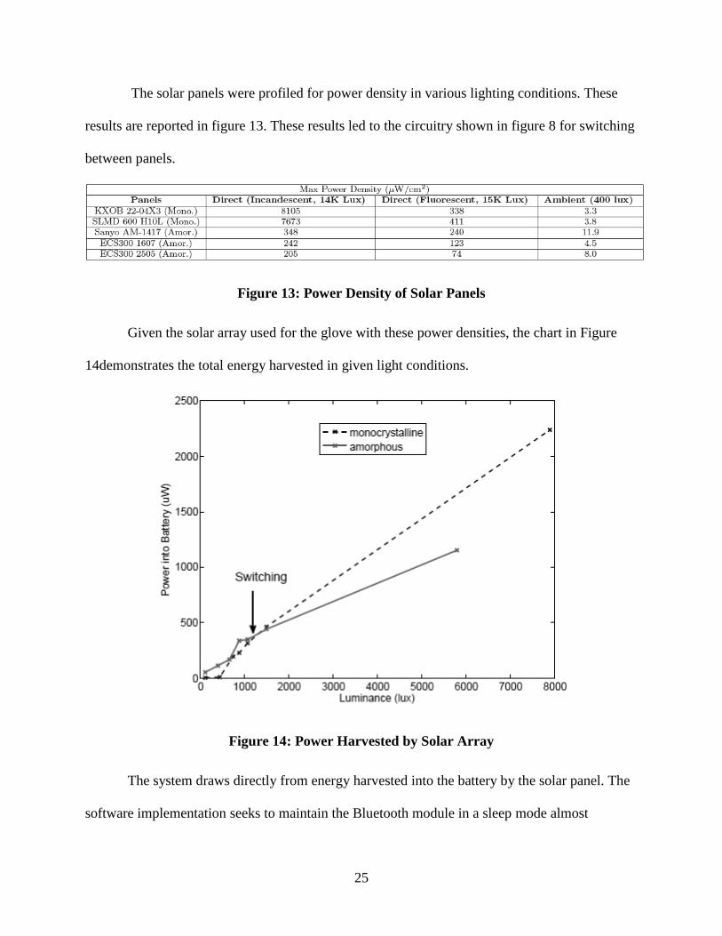
The solar panels were profiled for power density in various lighting conditions. These
results are reported in figure 13. These results led to the circuitry shown in figure 8 for switching
between panels.
Figure 13: Power Density of Solar Panels
Given the solar array used for the glove with these power densities, the chart in Figure
14demonstrates the total energy harvested in given light conditions.
Figure 14: Power Harvested by Solar Array
The system draws directly from energy harvested into the battery by the solar panel. The
software implementation seeks to maintain the Bluetooth module in a sleep mode almost

26
constantly. The rest of the system is duty cycled such that the microcontroller is active for
approximately 5 ms in a given cycle (cycle time varies between 100-500 ms depending on
system sensitivity). The wake-up circuit is also heavily duty cycled, being turned on long enough
for the DAC voltages to stabilize and having the opportunity to trigger an interrupt to the
microcontroller before being placed back into sleep mode. The accelerometer is only sampled
during an active gesture. This implementation represents an average power draw of between
0.2mA and 0.3mA when batching Bluetooth requests. The median power draw of this
implementation is shown in Figure 15.
Figure 15: Power Consumption/Harvested, Power-Aware Glove

27
4.2.2 Accuracy
The following results are reported as system accuracy results for the glove alone, as well
as sensor fusion with the headband for the totality of the tests. The accuracy tests were measured
using the hardware wake-up circuit for the flex sensors instead of the ADC. The thresholds are
similar and should be representative of the polling mechanism given a similar duty cycle rate.
The glove correctly identifies the gesture approximately 92.7% of the time, with a 3.1%
false positive (FP) rate and 4.1% false negative (FN) rate. Using sensor fusion with the headband
drops the accuracy to 85.5%, with 8.9% FP and 5.5 % FN while opening up accessibility to more
users.
These results show that gestures are correctly identified more than 90% of the time, and
that 57% of the error results in a missed gesture while 43% of the errors result in an erroneous
gesture. Adjusting thresholds by person and slower rotations increases this accuracy to more than
95% for the glove. The sensor fusion accuracy is reduced based on inaccuracy of the headband
creating conflicting gestures.
4.2.3 Latency
Latency results are average time to report results as measured by a DigiView digital
analyzer. Micro benchmarks are included:

28
Device/System Delay (ms)
Accelerometer - 6 samples 200
ADC - All Flex Sensors 27.8
MSP Wake-Up Time < 0.001
Standard System to Gesture Recognition (w/Rotate) 274 (474)
Gesture Recognition to Phone: < 1
Power-Aware System to Phone: Variable (Queuing)
Phone to Device 2400
Phone to Device w/ Sensor Fusion 3700
Table 2: Latency Results
These results show that on average, the phone will receive a gesture request between a
quarter and a half of a second after the gesture is performed. There is another two and a half
second delay between the phone and the device response over a 3G network. This timing is
likely reduced on a WiFi network depending on the given user’s connection. This response time
is within the tolerance range of the average user, but could be reduced with local caching for in-
home use.
4.2.4 Program Memory
The standard system consumes 7,736 bytes of program memory while the power-aware
system consumes 10,345 bytes.

29
4.3 Analysis
The results for the standard system present a viable device capable of lasting
approximately 10.1 days without any usage on a standard 1700mAh Li-Ion battery. Infrequent
usage (less than five gestures per hour) does not greatly impact the power consumption of the
system. The system operation time is lower bounded by every device in constant operation, a
cost of nearly 16.2 mA constant draw, resulting in operation time of approximately 4.4 days. For
total patient autonomy, the power aware system needs to be harvesting slightly more power into
the battery than it consumes. This cannot be done with the current system for anything besides
direct light. However, the Bluetooth Low Energy Stack (BLE) released earlier this year will
greatly reduce the time that the Bluetooth module must be active [37]. This innovation combined
with more efficient solar panels, a more efficient charging circuit, and a higher duty cycling ratio
creates a system capable of perpetual operation.
The system shows a high accuracy and low cost and can be considered as a viable option
for paralysis patients looking for a non-invasive solution for whole-home automation pending a
more thorough study using patients with varying degrees of paralysis or motor impairment.
Further, it proves that a platform of renewable energy driven wearable sensor-systems is a
potential field for further study and analysis. The system, if manufactured in quantities of greater
than 10,000 would cost less than $25 per standard glove device (power aware system is bounded
to the cost and efficiency of solar technology) and less than $2,000 for the home automation
system hardware. The use of this system could lead to substantial cost savings by minimizing
dependence on assistive care facilities.

30
4.3.1 Use of Hardware Wake-Up Circuit in Standard Glove System
The Hardware Wake-Up Circuit can be used in place of the standard glove system given
a few tradeoffs. First, the hardware wake up circuit reduces the necessity of maintaining the flex
sensor circuit constant power draw. The power consumption of the two measuring capabilities
are comparable, with an instantaneous consumption differing only 50uW, and both requiring a
set-up time for reference voltages(approximately 18ms for the ADC, approximately 60us for the
AD8804 DAC). Polling the ADC will consume slightly more power as the microcontroller must
remain in active mode (~600uW) during measurement mode, and the actual module must be on
during this additional time as well. The measurements take no more than 180us to process so this
overhead does not translate into much power consumption. Therefore, assuming an identical duty
cycle time, the two systems should result in comparable power. The overhead comes from
maintaining the flex resistors and the internal reference voltage and maintaining the
microcontroller during measurement modes. The power consumption of the systems is modeled
here:

31
Figure 16: Power Comparison of Wake-Up Circuit and ADC
The hardware wake-up circuit consumes approximately 5mW on average less than the
standard flex circuit. The power consumption of the ADC is mainly based on maintaining a
constant 2.5V internal reference. This can be mitigated by shutting off the reference voltage
between readings, but this produces an 18ms settling time for each measurement.This power
consumption reduction comes at the price of a significant increase in chip area, doubling the total
surface area of the board. The system complexity is slightly higher as multiple SPI devices must
be individually controlled and external references must be managed as they change. The cost of
the system does not increase by much given large quantities.

32
5. CONCLUSIONS
5.1 Summary
Two versions of a wearable computing solution to whole-home automation for paralysis
patients were developed. Each system utilizes a combination of flex sensors used as variable
resistance to calculate the bending angle of each finger with an accelerometer to create a
simplistic model of the human hand. This model is used for low-level gesture recognition
capable of live calculation on the microcontroller while maintaining a high duty cycling rate.
The two systems explore tradeoffs in system latency and power consumption. The first
system utilizes the on-board ADC and a polling mechanism to monitor the status of the sensors
to determine a gesture while maintaining an active Bluetooth connection for live updating of a
Smartphone UI. This approach is higher power (~8mA constant) but much lower latency
(~200ms). The second system adds an external hardware wake-up circuit and a solar panel array
in order to create a perpetually operating system while maintaining the Bluetooth module and
accelerometer in off states unless promted by gesture input to be utilized. This system is much
lower power (~200uA in ambient light, charging the battery at 1.8mA in direct light) but requires
a Bluetooth reconnect sequence during communication, greatly increasing the latency (> 4
seconds average from microcontroller to phone) and decreasing the accuracy of the system due
to Bluetooth instability.
Each of the systems is described from a high-level, and the implementation of each is
described such that a similar solution could be developed by a person with knowledge of the
field. The two systems are evaluated as functions of power consumption, accuracy, latency, cost,
and program memory, and are shown to be viable solutions.

33
5.2 Contributions
If productized, the systems as described could be implemented as whole-home
automation for paralysis and motor-impaired patients at a fraction of the cost of home healthcare,
while providing a patient with a broader range of autonomy that could positively impact the
patient’s quality of life.
The power-aware system contributes to the field of wearable computing by presenting a
system that in its current state is nearly perpetual. A similar branch of wearable sensor systems
could be developed to augment users with sensors more computationally expensive than current
health monitors.
5.3 Future Work
This thesis provides a basic framework for a gesture set capable of whole-home
automation, but does not explore extending this gesture set beyond a minimalist structure. The
system is capable of creating a gesture set expanding to at least the American Sign Language
(ASL) alphabet, with similar solutions modeling 203 words of ASL [38].
A further implementation of the power-aware glove using the Bluetooth Low Energy
stack and more efficient components could be putting energy back into the battery on average.
Instrumenting similar wearable sensors for perpetual operation could enable a human computing
interface augmentation capable of providing a wide-range of data to a user.

34
REFERENCES
[1] Frederick M. Maynard, Glenn G. Reynolds, Steven Fountain, Conal Wilmot, and Richard
Hamilton.” Neurological Prognosis after Traumatic Quadriplegia: Three-year experience of
California Regional Spinal Cord Injury Care System.” In Journal of Neurosurgery, May 1979.
[2] NSCISC. “Spinal Cord Injury Facts and Figures at a Glance.” February, 2012.
[3] Catherine Hawes, Miriam Rose, and Charles D. Phillips. “A National Study of Assisted
Living for the Frail Elderly: Results of a national survey of facilities.” In HHS Report, 1999.
[4] Margaret Chan and Robert Zoellick. World Report on Disability. World Health, 2011.
[5] Xiaoxiang Zheng, Xin Li, Jun Liu, Weidong Chen, and Yaoyao Hao. “A Portable
Wireless Eye Movement-Controlled Human-Computer Interface for the Disabled.” In CME,
pages 1 –5, April 2009.
[6] Zhou Ren, Jingjing Meng, Junsong Yuan, and Zhengyou Zhang. “Robust Hand Gesture
Recognition with Kinect Sensor.” In MM ’11, pages 759–760, New York, NY, USA, Nov-Dec
2011. ACM.
[7] Haiyuan Wu, Yosuke Kitagawa, Toshikazu Wada, Takekazu Kato, and Qian Chen.
“Tracking Iris contour with a 3D eye-model for Gaze Estimation.” In ACCV 2007, pages 688–
697, Berlin, Heidelberg, Nov 2007. Springer-Verlag.
[8] Timothy W. Hnat, Vijay Srinivasan, Jiakang Lu, Tamim I Sookoor, Raymond Dawson,
John Stankovic, and Kamin Whitehouse. “The hitchhiker's guide to successful residential sensing
deployments.” In Proceedings of the 9th ACM Conference on Embedded Networked Sensor
Systems, SenSys '11, pages 232-245, New York, NY, USA, Nov 2011. ACM.
[9] R. Watson. A Survey of Gesture Recognition Techniques. Technical report TCD-CD-93-
11, Department of Computer Science, Trinity College, Dublin 2, 1993.
[10] Rung-Huei Liang; Ming Ouhyoung, "A real-time continuous gesture recognition system
for sign language," Automatic Face and Gesture Recognition, 1998. Proceedings. Third IEEE
International Conference on. pp.558-567, 14-16 Apr 1998.
[11] Jay Taneja, Jaein Jeong, and David Culler. 2008. Design, Modeling, and Capacity
Planning for Micro-solar Power Sensor Networks. In Proceedings of the 7th international
conference on Information processing in sensor networks (IPSN '08) pp 407-418. 22-24 April,
2008.

35
[12] L. Dipietro, A.M. Sabatini, and P. Dario. A Survey of Glove-Based Systems and Their
Applications. Systems, Man, and Cybernetics, Part C: Applications and Reviews, IEEE
Transactions on, vol. 38 no.4, pp. 461 –482, July 2008.
[13] S. Vutinuntakasame, V.-R. Jaijongrak, and S. Thiemjarus. “An Assistive Body Sensor
Network Glove for Speech- and Hearing-Impaired Disabilities.” In BSN, pages 7 –12, May 2011.
[14] D.K. Sarji. HandTalk: Assistive Technology for the Deaf. Computer, vol. 41 no.7 pp. 84
–86, July 2008.
[15] R. Wada, T. Nonaka, and T. Hase. “Glove Input Interface with Switches on Fingertips.”
In ISCE, pages 95 –97, June 2011.
[16] Holger Kenn, Friedrich Van Megen, and Robert Sugar. “A Glove-based Gesture Interface
for Wearable Computing Applications.” IFAWC, pages 1 –10, March 2007.
[17] P. Bonato. “Wearable sensors/systems and their impact on biomedical engineering.”
Engineering in Medicine and Biology Magazine, IEEE, 22(3):18 –20, May-June 2003.
[18] Varadan Vijay K., Kumar Prashanth S., Oh Sechang, Kegley Lauren, and Rai Pratyush.
“e-bra With Nanosensors for Real Time Cardiac Health Monitoring and Smartphone
Communication.” In Journal of Nanotechnology in Engineering and Medicine, May 2011.
[19] V. K. Varadan, P. S. Kumar, S. Oh, H. Kwon, P. Rai, N. Banerjee, and R. E. Harbaugh.
“e-Nanoflex Sensor System: Smartphone-based Roaming Health Monitor.” In Journal of
Nanotechnology in Engineering and Medicine, May 2011.
[20] P. S. Kumar, S. Oh, P. Rai, H. Kwon, N. Banerjee, and V. K. Varadan. “Design and
Implementation of a Bluetooth-based Band-aid pulse Rate sensor.” In SPIE Nano- bio- info- tech
Sensors and Systems, March, 6 2011.
[21] Yoonmyung Lee, Gyouho Kim, Suyoung Bang, Yejoong Kim, Inhee Lee, Prabal Dutta,
Dennis Sylvester, and David Blaauw. “A Modular 1mm3 Die-Stacked Sensing Platform with
Optical Communication and Multi-Modal Energy Harvesting”. In ISSCC 2012. February 2012.
[22] Jacob Sorber, Alexander Kostadinov, Matthew Garber, Matthew Brennan, Mark D.
Corner, and Emery D. Berger. “Eon: A Language and Runtime System for Perpetual Systems.”
In Proc. ACM SenSys, Syndey, Australia, November 2007.
[23] Pei Zhang, Christopher M. Sadler, Stephen A. Lyon, and Margaret Martonosi. “Hardware
design experiences in zebranet.” In SenSys '04: Proceedings of the 2nd
international conference
36
on Embedded networked sensor systems, pages 227-238, New York, NY, USA, Nov 2004.
ACM.
[24] Aman Kansal, Jason Hsu, Mani B Srivastava, and Vijay Raghunathan. “Harvesting
aware power management for sensor networks.” In 43rd Design Automation Conference(DAC),
July 2006.
[25] Nilanjan Banerjee, Mark D. Corner, and Brian Neil Levine. “An Energy-Efficient
Architecture for DTN Throwboxes.” In IEEE Infocom, May 2007.
[26] Lohit Yerva, Brad Campbell, Apoorva Bansal, Thomas Schmid, and Prabal Dutta.
“Grafting Energy-Harvesting Leaves onto the Sensornet Tree.” In Proceedings of the 11th
international conference on Information Processing in Sensor Networks, IPSN '12, pages 197-
208, New York, NY, USA, 2012. ACM.
[27] Jeremy Gummeson, Shane S. Clark, Kevin Fu, and Deepak Ganesan. “On the Limits of
Effective Hybrid Micro-Energy Harvesting on Mobile Crowd Sensors.” In Proceedings of the 8th
international conference on Mobile systems, applications, and services, MobiSys '10, pages 195-
208, New York, NY, USA, June 2010. ACM.
[28] W. Yuan and K. Nahrstedt. “Energy-Efficient Soft Real-time CPU Scheduling for Mobile
Multimedia Systems.” In Proceedings of the Symposium on Operating Systems Principles, pages
149-163, Bolton Landing, NY, October 2003.
[29] F. Douglis, P. Krishnan, and B. N. Bershad. “Adaptive disk spin-down policies for
mobile computers.” In Proceedings of the 2nd Symposium on Mobile and Location-Independent
Computing, April 1995.
[30] D. P. Helmbold, D. D. E. Long, and B. Sherrod. “A Dynamic Disk Spin-Down
Technique for Mobile Computing.” In Proceedings of the Second ACM International Conference
on Mobile Computing. MobiCom ’96, November 1996.
[31] Ahmad Rahmati and Lin Zhong. “Context-for-Wireless: Context-Sensitive Energy-
efficient wireless data transfer.” In Proceedings of Mobisys, Puerto Rico, USA, June 2007.
[32] Jacob Sorber, Nilanjan Banerjee, Mark D. Corner, and Sami Rollins. “Turducken:
Hierarchical Power Management for Mobile Devices.” In Proceedings of ACM MobiSys, Seattle,
WA, June 2005.
[33] Nilanjan Banerjee, Jacob Sorber, Mark D. Corner, Sami Rollins, and Deepak Ganesan.
“Triage: Balancing Energy and Quality of Service in a Microserver.” In Proceedings of ACM
MobiSys, Puerto Rico, USA, June 2007.

37
[34] Yuvraj Agarwal, Steve Hodges, Ranveer Chandra, James Scott, Paramvir Bahl, and
Rajesh Gupta. “Somniloquy: Maintaining network connectivity while your computer sleeps.”
Unpublished.
[35] P. Kumar, S. Oh, N. Banerjee, V. K. Varadan, “Wearable Remote Brain-Machine
Interface Using Smartphones.” International Conference on Smart Materials, Structures, and
Systems, Italy, June 2012.
[36] Nilanjan Banerjee, Sami Rollins, and Kevin Moran. “Automating Energy Management in
Green Homes.” In HomeNets, August 2011.
[37] Bluetooth, S. I. G. "Bluetooth specification version 4.0." Bluetooth SIG Standard.2009.
[38] S.S. Fels, “Glove-Talk: A Nerual Network interface between a Data-Glove and Speech
Synthesizer,” Neural Networks, IEEE Transactions on , vol.4, no.1, pp.2,8, Jan 1993.
[39] Gabe Cohn, Daniel Morris, Shwetak N. Patel, and Desney S. Tan. “Your Noise is my
Command: Sensing Gestures using the Body as an Antenna.” In CHI, CHI ’11, pages 791–800,
New York, NY, USA, May 2011. ACM.
[40] R. Paradiso, G. Loriga, and N. Taccini. “A wearable health care system based on knitted
integrated sensors.” Information Technology in Biomedicine, IEEE Transactions on, vol. 9 no.3
pp. 337 –344, Sept. 2005.
