geräte-handbuch nd 280 - heidenhain
TRANSCRIPT
Operating Instructions
ND 280
English (en)11/2013

ND 280 screen
1
2
3
4
5
ND 280 front panel
7
6

Controls and displays
1 Status bar
Current operating mode: Actual Value, Distance-To-Go
Current display mode for input X1
SCL shown in black: Scaling factor is active
COMP shown in black: Error compensation or axis-error compensation is active for the currently displayed axis .
Elapsed time of running stopwatch: If the stopwatch is stopped, the box appears dimmed.
mm, inch, DEG, DMS or rad: Currently active unit of measure
Currently active datum: The ND 280 allows you to work with two different datums.
Indicates the soft-key page (soft-key row) you are currently on.
2 Position display: Current position value (length or angle)
3 Message line for displaying information, errors or warnings
4 Status display:
SET: If you enter a new value during datum setting, the SET symbol will start flashing.REF: The REF symbol is flashing until the reference mark evaluation for the displayed axis has been
completed (if an incremental encoder is connected).
5 and 6 Soft keys and soft-key buttons for executing functions
1,2,3,4... Numeric input keys
ENTER Use the ENTER key to confirm your entry or to return to the previous screen.
C Use the C key to clear an entry, acknowledge an error message or return to the previous screen.
The NAVIGATION key moves through the soft-key pages (soft-key rows).
7 Use the UP or DOWN arrow key to move between fields within a form or menu items (parameters) within a menu.

ND 280 rear panel
���������
1
23
Connections
1 Power switch
2 Power connection with fuse
3 Ground (protective earthing)
X1 for a HEIDENHAIN encoder with 11 µApp, 1 Vpp or EnDat interface (purely serial)
X32/X31 Two serial ports for data transfer: RS-232-C/V.24 (X31) and USB Type B (UART, X32)
ND 280 5
In
tro
du
cti
onIntroduction
Software version
The software version is shown on the power-up screen of the ND 280.
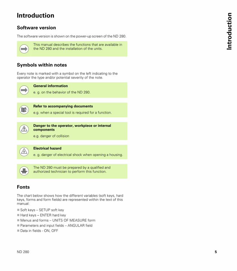
Symbols within notes
Every note is marked with a symbol on the left indicating to the operator the type and/or potential severity of the note.
Fonts
The chart below shows how the different variables (soft keys, hard keys, forms and form fields) are represented within the text of this manual:
Soft keys – SETUP soft keyHard keys – ENTER hard keyMenus and forms – UNITS OF MEASURE form Parameters and input fields – ANGULAR field Data in fields - ON, OFF
This manual describes the functions that are available in the ND 280 and the installation of the units.
General information
e. g. on the behavior of the ND 280.
Refer to accompanying documents
e.g. when a special tool is required for a function.
Danger to the operator, workpiece or internal components
e.g. danger of collision
Electrical hazard
e. g. danger of electrical shock when opening a housing.
The ND 280 must be prepared by a qualified and authorized technician to perform this function.


ND 280 7
I – 1 ND 280 position display unit ..... 12I – 2 Fundamentals of positioning ..... 13
Datums ..... 13Actual position, nominal position and distance-to-go ..... 14Absolute workpiece positions ..... 15Incremental workpiece positions ..... 15Incremental position encoders ..... 16Absolute position encoders ..... 16Reference marks ..... 17
I – 3 Basic functions of the ND 280 ..... 18ND 280 power-up ..... 18Reference mark evaluation ..... 19
Working without reference mark evaluation ..... 19ND 280 shutdown ..... 19Standard screen layout ..... 20Soft-key functions on the standard screen ..... 21Data input ..... 22Integrated help system ..... 23Data input forms ..... 24
Instruction box messages ..... 24Error messages ..... 24
I – 4 Job Setup ..... 25Operating modes ..... 25Datum setting ..... 26
Setting the display value for one axis ..... 26Calling the JOB SETUP menu ..... 27Unit of measure ..... 28Scaling factor ..... 29Value for datum point ..... 30Stopwatch ..... 30Console adjustment ..... 31Language ..... 31
I – 5 Error messages ..... 32Overview ..... 32
I Working with the ND 280 position display unit ..... 11

8
II – 1 Installation and electrical connection ..... 34Items supplied ..... 34
Optional accessories ..... 34Mounting ..... 35
Environmental conditions ..... 35Mounting location ..... 35ND 280 – Mounting and installation ..... 35
Electromagnetic compatibility/CE compliance ..... 36Electrical connection ..... 37
Electrical requirements ..... 37Wiring the power connector ..... 37Grounding ..... 37
Preventative maintenance or repair ..... 38Connecting the encoders ..... 38
D-sub connection X1 (15-pin, female) for the following input signals ..... 38II – 2 Installation Setup ..... 40
INSTALLATION SETUP menu ..... 40Setting up the encoder ..... 41
Incremental linear encoder ..... 42Incremental rotary encoder ..... 43Absolute encoder ..... 44Using an absolute multiturn rotary encoder as a linear encoder ..... 44
Configuring the display ..... 45Linear encoder ..... 45Rotary encoder ..... 45
Counter settings ..... 46Error compensation ..... 47
Linear error compensation (not for rotary encoders) ..... 48Non-linear error compensation ..... 49
Setting up the serial port ..... 53Setting up the data interface ..... 53
Diagnostics ..... 55Keypad test ..... 55Display test ..... 55Encoder test ..... 56Power supply ..... 58
II Installation, specifications ..... 33
ND 280 9
II – 3 Encoder parameters ..... 59Table values ..... 59HEIDENHAIN linear encoders ..... 59HEIDENHAIN rotary encoders ..... 60
II – 4 Data interface ..... 61Data communication ..... 61Serial data transfer with the Import or Export function ..... 62
Data transfer from the ND 280 to a printer ..... 62Data transfer from the ND 280 to a PC ..... 62Importing data into the ND 280 from a PC ..... 63Data format ..... 63Control characters ..... 63
Software update (firmware update) installation ..... 64Wiring the connecting cable ..... 65
USB Type B (UART), socket as per IEC 61076-3-108 ..... 66External operation via RS-232-C/V.24 or USB interface ..... 67
Key commands ..... 67Description of key commands ..... 68Key is pressed (TXXXX commands) ..... 69Output of screen contents (AXXXX commands) ..... 69Execute function (FXXXX commands) ..... 73Execute special function (SXXXX commands) ..... 73
II – 5 Measured value output ..... 74Alternatives for starting measured value output ..... 74Measured-value output via the serial data interface X31 or X32 ..... 74
Propagation times ..... 75Duration of measured value transfer ..... 76Example: Data sequence during measured-value output ..... 76
10
II – 6 Input and output of parameter list and error compensation table ..... 77Text file ..... 77Output format of the parameter list ..... 78
First line ..... 78Second line ..... 78Subsequent lines for the individual parameters ..... 78Last line ..... 78
Example of a parameter list ..... 79ND 280 with rotary encoder connected to input X1 ..... 79
Output format of the error compensation table ..... 81First line ..... 81Second line ..... 81Third line ..... 81Fourth line ..... 81Fifth line ..... 82Sixth line ..... 83Subsequent lines for further compensation values ..... 83Last line ..... 83
Examples of error compensation tables ..... 84ND 280 with linear encoder connected to input X1 ..... 84
II – 7 Specifications for ..... 86ND 280 ..... 86
II – 8 Dimensions ..... 88ND 280 ..... 88
II – 9 Accessories ..... 89ID numbers for accessories ..... 89Mounting base for installation in 19-inch electrical cabinet ..... 90

11
Working with
the ND 280 position
display unit

12 I Working with the ND 280 position display unit
I – 1
ND
28
0 p
osit
ion
dis
pla
y u
nit I – 1 ND 280 position display unit
The ND 280 position display unit from HEIDENHAIN is designed for measuring devices, adjustment and testing equipment, automated tasks, as well as infeed and positioning tasks with one axis that can be moved manually.
A HEIDENHAIN linear/angular/rotary encoder or a length gauge with 11 µApp, 1 Vpp or EnDat (purely serial) interface can be connected to the ND 280.
The following functions are available on the ND 280:
Multilingual user guidance: Language can be selected by the userREF reference-mark evaluation for distance-coded or single
reference marks Length and angle displayDistance-To-Go or Actual Value operating mode Two datums Scaling factor StopwatchReset or Preset function Linear or non-linear error compensation for axis-error
compensation
There are two serial ports for transmitting measured values, compensation values or configuration parameters to a PC or printer: The data can be transferred via the RS 232-C/V.24 or the USB Type B (UART) interface. It is also possible to download software via the serial interface.
Diagnostic functions for testing the encoder, the keyboard, the screen and the supply voltage
The integrated help system provides information and assistance in any situation.
Fig. I.1 ND 280

13
I – 2
Fu
nd
am
en
tals
of
po
sit
ion
ingI – 2 Fundamentals of positioning
Datums
The workpiece drawing identifies a certain point on the workpiece (usually a corner) as the absolute datum and perhaps one or more other points as relative datums.
The datum setting procedure establishes these points as the origin of the absolute or relative coordinate systems. The workpiece, which is aligned with the machine axes, is moved to a certain position relative to the length gauge and the display is set either to zero or to another appropriate value.
Fig. I.2 Length gauge without datum setting: Unknown assignment of measured values to positions
Fig. I.3 Length gauge with datum setting: Known assignment of measured values to positions
�
�
�
�
�
�
�
�
�
�

14 I Working with the ND 280 position display unit
I – 2
Fu
nd
am
en
tals
of
po
sit
ion
ing Actual position, nominal position and
distance-to-go
The position of the length gauge at any given moment is called the actual position, while the position that the length gauge is to move to is called the nominal position. The distance from the nominal position to the actual position is called the distance-to-go (see Fig. I.4).
Fig. I.4 Nominal position S, actual position I and distance-to-go R
��
�
15
I – 2
Fu
nd
am
en
tals
of
po
sit
ion
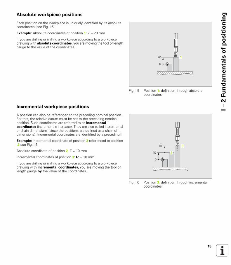
ingAbsolute workpiece positions
Each position on the workpiece is uniquely identified by its absolute coordinates (see Fig. I.5).
Example: Absolute coordinates of position 1: Z = 20 mm
If you are drilling or milling a workpiece according to a workpiece drawing with absolute coordinates, you are moving the tool or length gauge to the value of the coordinates.
Incremental workpiece positions
A position can also be referenced to the preceding nominal position. For this, the relative datum must be set to the preceding nominal position. Such coordinates are referred to as incremental coordinates (increment = increase). They are also called incremental or chain dimensions (since the positions are defined as a chain of dimensions). Incremental coordinates are identified by a preceding I.
Example: Incremental coordinate of position 3 referenced to position 2 see Fig. I.6.
Absolute coordinate of position 2: Z = 10 mm
Incremental coordinates of position 3: IZ = 10 mm
If you are drilling or milling a workpiece according to a workpiece drawing with incremental coordinates, you are moving the tool or length gauge by the value of the coordinates.
Fig. I.5 Position 1: definition through absolute coordinates
� �
Fig. I.6 Position 3: definition through incremental coordinates
�
�
�
�

16 I Working with the ND 280 position display unit
I – 2
Fu
nd
am
en
tals
of
po
sit
ion
ing Incremental position encoders
Incremental linear and rotary encoders from HEIDENHAIN convert the movements of, for example, a length gauge into electrical signals. A position display unit, such as the ND 280, constantly evaluates these signals and calculates the actual positions of the length gauge, which it displays as a numerical value on the screen.
If there is a power interruption, the calculated position will no longer correspond to the actual position of the length gauge. When power is restored, you can re-establish this relationship with the aid of the reference marks on the position encoders and the ND 280's reference mark evaluation feature.
Absolute position encoders
Absolute linear and angle encoders from HEIDENHAIN transmit the absolute position value to the position display unit immediately after switch-on. This way the assignment of the actual position to the position of, for example, a length gauge is re-established directly after switch-on.
The encoder reads the absolute position information directly from the scale graduation (see Fig. I.8), and transmits it serially to the position display unit via the bidirectional EnDat interface.
Fig. I.7 Linear position encoder, here for the X axis
�
Fig. I.8 Scale grating for absolute position encoders

17
I – 2
Fu
nd
am
en
tals
of
po
sit
ion
ingReference marks
Encoders normally contain one or more reference marks (see Fig. I.9) which the ND 280's reference mark evaluation feature uses to re-establish datum positions after a power interruption. There are two main options available for reference marks: fixed and distance-coded.
Encoders with distance-coded reference marks have marks separated by a specific encryption pattern that allows the ND 280 to use any two pair of marks along the length of the encoder to re-establish the prior datums. This configuration means that the operator only has to travel a very short distance, anywhere along the encoder, to re-establish the datums when the ND 280 is turned back on.
Encoders with fixed reference marks have one or more marks on fixed intervals. To re-establish the datums correctly, it is necessary to use the same exact reference mark, during the reference mark evaluation routine, that was used when the datum was first established.
Fig. I.9 Linear scales – with distance-coded reference marks (upper illustration) and one reference mark (lower illustration)
Danger to workpiece!
The established datums cannot be restored from one power cycle to the next if the reference marks were not crossed before the datums were set.
18 I Working with the ND 280 position display unit
I – 3
Ba
sic
fu
ncti
on
s o
f th
eN
D2
80 I – 3 Basic functions of the ND 280
ND 280 power-up
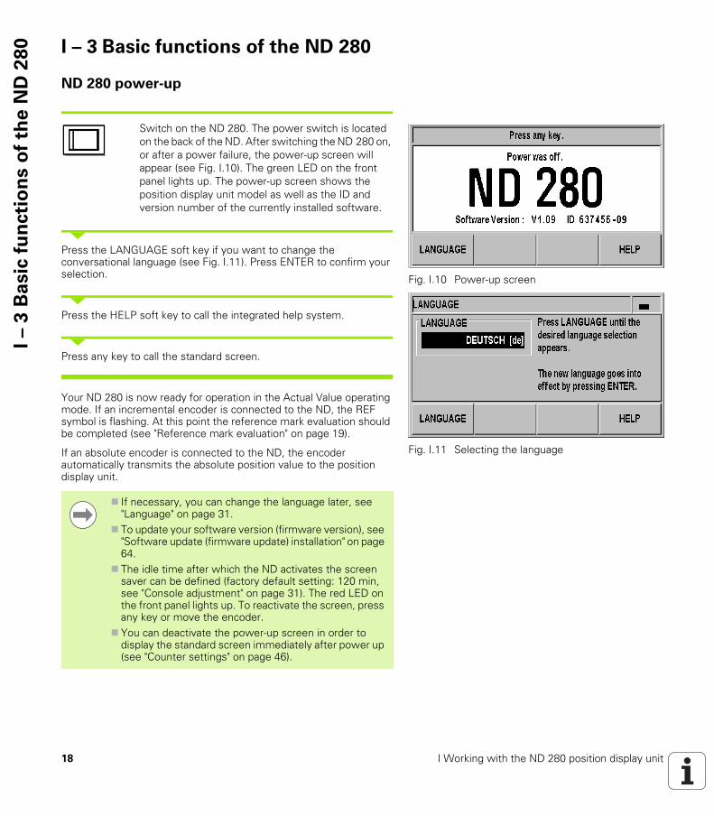
Switch on the ND 280. The power switch is located on the back of the ND. After switching the ND 280 on, or after a power failure, the power-up screen will appear (see Fig. I.10). The green LED on the front panel lights up. The power-up screen shows the position display unit model as well as the ID and version number of the currently installed software.
Press the LANGUAGE soft key if you want to change the conversational language (see Fig. I.11). Press ENTER to confirm your selection.
Press the HELP soft key to call the integrated help system.
Press any key to call the standard screen.
Your ND 280 is now ready for operation in the Actual Value operating mode. If an incremental encoder is connected to the ND, the REF symbol is flashing. At this point the reference mark evaluation should be completed (see "Reference mark evaluation" on page 19).
If an absolute encoder is connected to the ND, the encoder automatically transmits the absolute position value to the position display unit.
Fig. I.10 Power-up screen
Fig. I.11 Selecting the language
If necessary, you can change the language later, see "Language" on page 31.
To update your software version (firmware version), see "Software update (firmware update) installation" on page 64.
The idle time after which the ND activates the screen saver can be defined (factory default setting: 120 min, see "Console adjustment" on page 31). The red LED on the front panel lights up. To reactivate the screen, press any key or move the encoder.
You can deactivate the power-up screen in order to display the standard screen immediately after power up (see "Counter settings" on page 46).
19
I – 3
Ba
sic
fu
ncti
on
s o
f th
eN
D2
80Reference mark evaluation
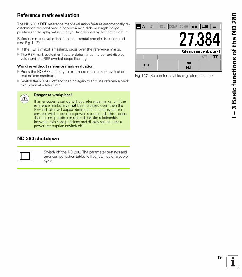
The ND 280's REF reference mark evaluation feature automatically re-establishes the relationship between axis-slide or length gauge positions and display values that you last defined by setting the datum.
Reference mark evaluation if an incremental encoder is connected (see Fig. I.12):
If the REF symbol is flashing, cross over the reference marks. The REF mark evaluation feature determines the correct display
value and the REF symbol stops flashing.
Working without reference mark evaluation
Press the NO REF soft key to exit the reference mark evaluation routine and continue.
Switch the ND 280 off and then on again to activate reference mark evaluation at a later time.
ND 280 shutdown
Switch off the ND 280. The parameter settings and error compensation tables will be retained on a power cycle.
Fig. I.12 Screen for establishing reference marks
Danger to workpiece!
If an encoder is set up without reference marks, or if the reference marks have not been crossed over, then the REF indicator will appear dimmed, and datums set from any axis will be lost once power is turned off. This means that it is not possible to re-establish the relationship between axis slide positions and display values after a power interruption (switch-off).
20 I Working with the ND 280 position display unit
I – 3
Ba
sic
fu
ncti
on
s o
f th
eN
D2
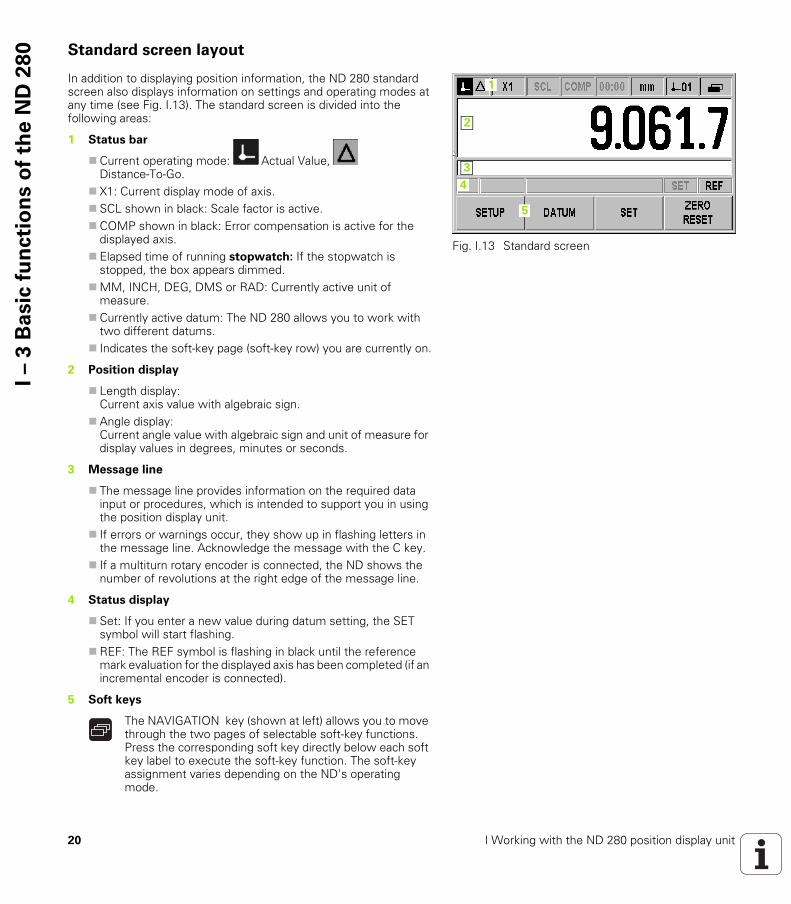
80 Standard screen layout
In addition to displaying position information, the ND 280 standard screen also displays information on settings and operating modes at any time (see Fig. I.13). The standard screen is divided into the following areas:
Fig. I.13 Standard screen
1
4
3
2
5
1 Status bar
Current operating mode: Actual Value, Distance-To-Go.
X1: Current display mode of axis. SCL shown in black: Scale factor is active.COMP shown in black: Error compensation is active for the
displayed axis. Elapsed time of running stopwatch: If the stopwatch is
stopped, the box appears dimmed.MM, INCH, DEG, DMS or RAD: Currently active unit of
measure.Currently active datum: The ND 280 allows you to work with
two different datums. Indicates the soft-key page (soft-key row) you are currently on.
2 Position display
Length display:Current axis value with algebraic sign.
Angle display:Current angle value with algebraic sign and unit of measure for display values in degrees, minutes or seconds.
3 Message line
The message line provides information on the required data input or procedures, which is intended to support you in using the position display unit.
If errors or warnings occur, they show up in flashing letters in the message line. Acknowledge the message with the C key.
If a multiturn rotary encoder is connected, the ND shows the number of revolutions at the right edge of the message line.
4 Status display
Set: If you enter a new value during datum setting, the SET symbol will start flashing.
REF: The REF symbol is flashing in black until the reference mark evaluation for the displayed axis has been completed (if an incremental encoder is connected).
5 Soft keys
The NAVIGATION key (shown at left) allows you to move through the two pages of selectable soft-key functions. Press the corresponding soft key directly below each soft key label to execute the soft-key function. The soft-key assignment varies depending on the ND's operating mode.
21
I – 3
Ba
sic
fu
ncti
on
s o
f th
eN
D2
80Soft-key functions on the standard screen
There are two pages (rows) of soft-key functions. Use the NAVIGATION key (shown at left) to move through the pages. The page indicator in the status bar shows the number of pages. The darkened page indicates the page you are currently on. This manual provides more information about each soft key on the pages indicated in the table below.
Soft key page 1:
Soft key page 2:
Fig. I.14 Page indicator
Soft key Function Page
SETUP Opens the JOB SETUP menu and provides access to the INSTALLATION SETUP soft key.
Page 25
DATUM Switches the datum (see datum display in the status bar).
Page 26, Page 30,
PRESET Sets the axis value to the preset value for the datum.
Page 26
RESET Actual Value mode: Resets the selected datum of the displayed axis to zero.
Distance-To-Go mode: Resets the distance-to-go for the displayed axis to zero.
Page 26
Soft key Function Page
HELP Calls the integrated help system. Page 23
PRINT Transmits the current measured value to a connected PC or printer via the serial interface.
Page 74
Distance-to-goon
Switches the display between operating modes Actual Value/Distance-To-Go.
Page 25
MMinch
DEGDMSrad
Switches the position display (length or angle) to the displayed unit of measure. The selected unit of measure is shown in the status bar.
Page 28
22 I Working with the ND 280 position display unit
I – 3
Ba
sic
fu
ncti
on
s o
f th
eN
D2
80 Data input
Use the keypad to enter numeric values within each field. The ENTER key will confirm the entry within a field and return to the
previous screen. Press the C key to clear entries, acknowledge error messages or
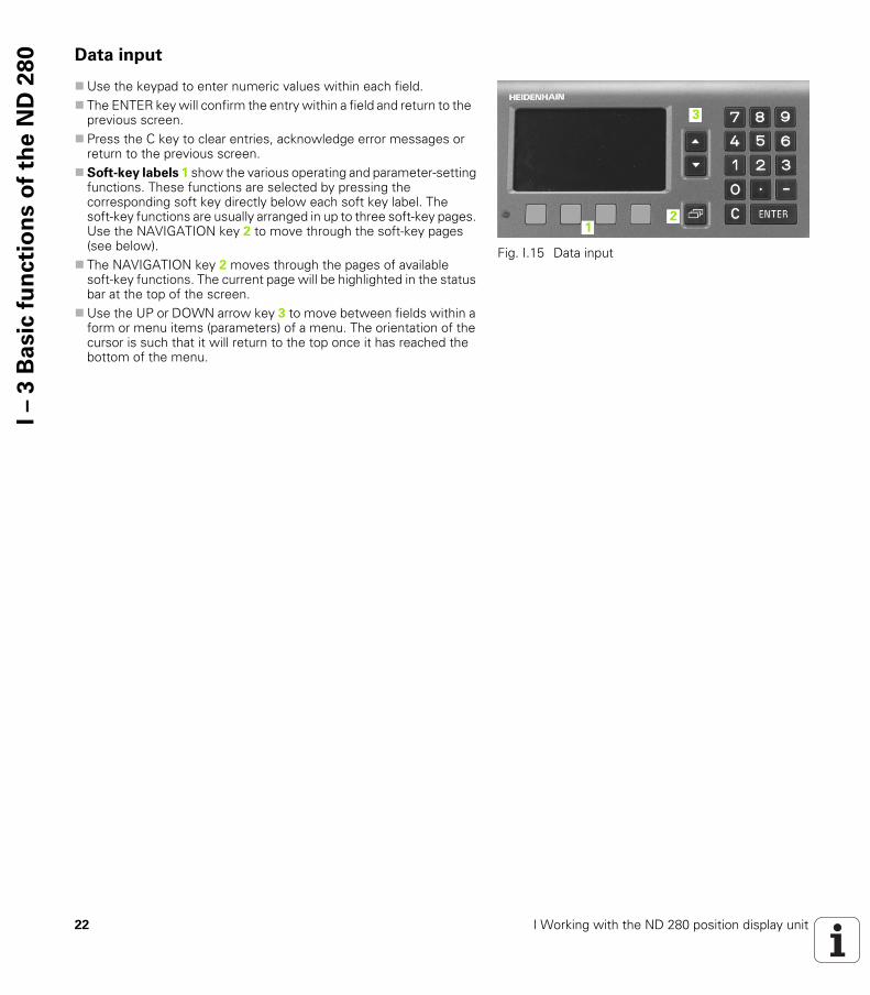
return to the previous screen.Soft-key labels 1 show the various operating and parameter-setting
functions. These functions are selected by pressing the corresponding soft key directly below each soft key label. The soft-key functions are usually arranged in up to three soft-key pages. Use the NAVIGATION key 2 to move through the soft-key pages (see below).
The NAVIGATION key 2 moves through the pages of available soft-key functions. The current page will be highlighted in the status bar at the top of the screen.
Use the UP or DOWN arrow key 3 to move between fields within a form or menu items (parameters) of a menu. The orientation of the cursor is such that it will return to the top once it has reached the bottom of the menu.
Fig. I.15 Data input
12
3
23
I – 3
Ba
sic
fu
ncti
on
s o
f th
eN
D2
80Integrated help system
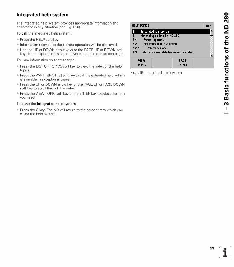
The integrated help system provides appropriate information and assistance in any situation (see Fig. I.16).
To call the integrated help system:
Press the HELP soft key. Information relevant to the current operation will be displayed. Use the UP or DOWN arrow keys or the PAGE UP or DOWN soft
keys if the explanation is spread over more than one screen page.
To view information on another topic:
Press the LIST OF TOPICS soft key to view the index of the help topics.
Press the PART 1/[PART 2] soft key to call the extended help, which is available in exceptional cases.
Press the UP or DOWN arrow key or the PAGE UP or PAGE DOWN soft key to scroll through the index.
Press the VIEW TOPIC soft key or the ENTER key to select the item you need.
To leave the integrated help system:
Press the C key. The ND will return to the screen from which you called the help system.
Fig. I.16 Integrated help system

24 I Working with the ND 280 position display unit
I – 3
Ba
sic
fu
ncti
on
s o
f th
eN
D2
80 Data input forms
Information required for various operational functions and setup parameters is entered through a data input form. These forms will appear after selecting features that require any additional information. Each form provides specific fields for entering the required information.
To confirm the changes:
Press the ENTER key.
To ignore the changes and return to the previous screen:
Press the C key.
Instruction box messages
Whenever a menu or form is open, an instruction box will also open immediately to the right of it (see Fig. I.17). This message box will provide information to the operator on what the chosen function does and present instructions on the available options.
Error messages
If an error occurs while you are working with the ND, the message will appear on the display and provide an explanation of what caused the error.
To acknowledge the error message:
Press the C key.
Fig. I.17 Example of instruction box messages
If a new error occurs before the last error has been acknowledged, the last error that has occurred will be displayed. After the last error has been acknowledged, the previous error will be displayed again. The ND always stores the last error of each error category for acknowledgment (see "Error messages" on page 32).

25
I – 4
Jo
b S
etu
pI – 4 Job Setup
Operating modes
The ND 280 has two operating modes: Actual Value and Distance-To-Go.
In the Actual Value operating mode, the ND 280 always displays the current actual position of the length gauge, relative to the active datum. In this mode, all moves are done by traveling until the display matches the nominal position that is required.
The Distance-To-Go feature enables you to approach nominal positions simply by traversing to display value zero. Proceed as follows:
Press the DELTA MODE ON soft key to switch the operating mode (see "Soft-key functions on the standard screen" on page 21): The display value is zero.
Use the numeric keys to enter the nominal position you want to move to and confirm with the ENTER key: The distance-to-go is displayed.
Traverse the axis until the display value is zero. If required, enter the next nominal position and confirm with the
ENTER key: Traverse the axis until the display value is zero. To leave the Distance-To-Go operating mode: Press the DELTA
MODE OFF soft key.
Fig. I.18 Actual Value symbol (highlighted) in the status display
Status bar Function
Shows current actual position
Displays current distance from the nominal position
Algebraic sign of distance-to-go:
The distance-to-go has a positive sign if the axis direction from the actual towards the nominal position is negative.
The distance-to-go has a negative sign if the axis direction from the actual towards the nominal position is positive.

26 I Working with the ND 280 position display unit
I – 4
Jo
b S
etu
p Datum setting
The datum setting procedure assigns the matching display value to a known position. With the ND 280 position display unit, you can set two separate datum points.
During operation, you can reset the display value of the axis to zero, or preset it to a defined or new value.
Setting the display value for one axis
Select soft-key page 1 on the standard screen. If necessary, press the DATUM soft key to select the datum you
want to set. To reset the display value to zero, press the RESET. As an
alternative, you can use the numeric keys to enter the number zero and press ENTER to confirm your entry.
You can also set any desired display value by entering the new value with the numeric keypad. As a result, the SET symbol in the status display starts flashing in . Press the ENTER key to confirm the entered numerical value.
To set the display value to the preset value for the datum point (see "Value for datum point" on page 30), press the PRESET soft key.
Fig. I.19 Standard screen with soft-key page 1
With RESET, you set the current datum to zero at the current position for that axis:
If the Actual Value mode is active, the display value is zero.
If the Distance-To-Go mode is active, the distance remaining to the position of the new datum is displayed.

27
I – 4
Jo
b S
etu
pCalling the JOB SETUP menu
The ND 280 offers two categories for setting up operating parameters: JOB SETUP and INSTALLATION SETUP.
The JOB SETUP parameters are used to accommodate specific machining requirements for each job.
The INSTALLATION SETUP menu is used to establish encoder, display and communication parameters (see "INSTALLATION SETUP menu" on page 40).
To call the JOB SETUP menu:
Press the SETUP soft key to open the JOB SETUP menu.
When in the JOB SETUP menu, the following soft keys will be available (see Fig. I.20):
INSTALLATION SETUPPress to begin accessing the INSTALLATION SETUP parameters (see "INSTALLATION SETUP menu" on page 40).
IMPORT/EXPORTOperating parameter information can be imported or exported over the serial port. (See "Serial data transfer with the Import or Export function" on page 62). Press this soft key to call the two following soft keys:
Press IMPORT to download operating parameters from a PC. Press EXPORT to upload the current operating parameters to a PC. To exit, press the C key.
HELPThis soft key will open on-line help.
Press the NAVIGATION key to move through the pages of menu parameters. To view and change menu parameters, use the UP/DOWN arrow key to highlight the parameter of interest and press the ENTER key.
On the following pages you will find more information on the menu parameters.
Fig. I.20 JOB SETUP menu
Fig. I.21 JOB SETUP menu
28 I Working with the ND 280 position display unit
I – 4
Jo
b S
etu
p Unit of measure
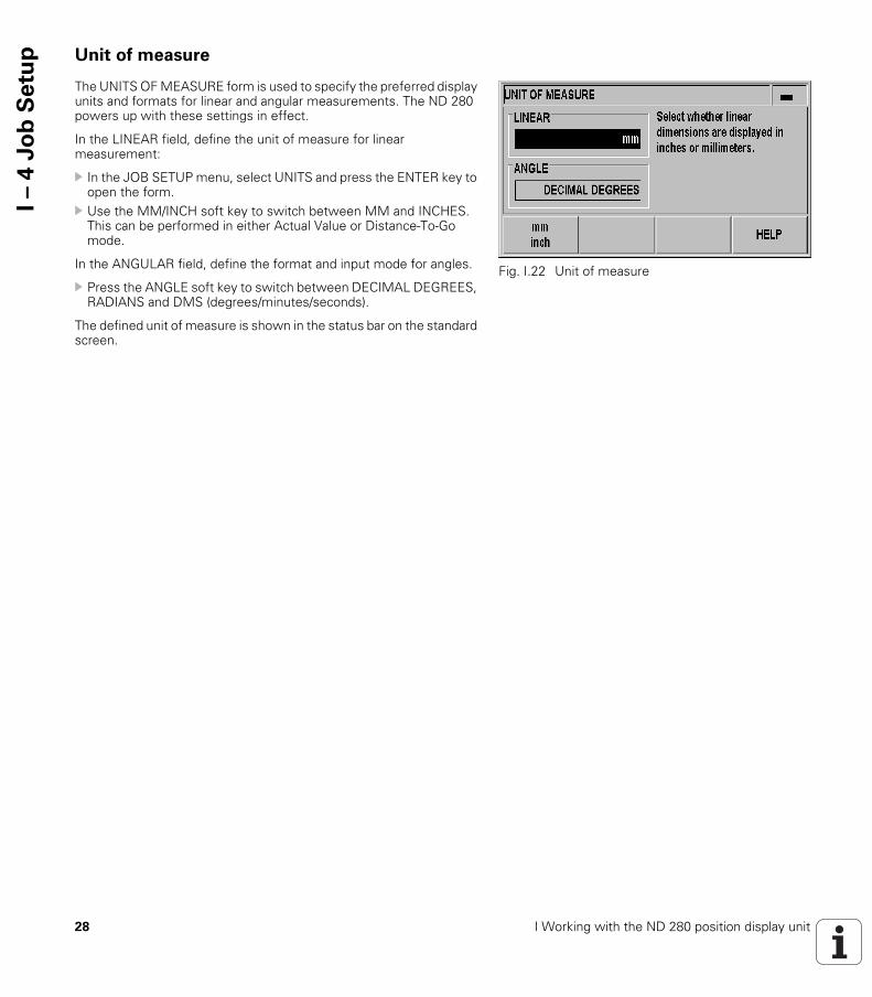
The UNITS OF MEASURE form is used to specify the preferred display units and formats for linear and angular measurements. The ND 280 powers up with these settings in effect.
In the LINEAR field, define the unit of measure for linear measurement:
In the JOB SETUP menu, select UNITS and press the ENTER key to open the form.
Use the MM/INCH soft key to switch between MM and INCHES. This can be performed in either Actual Value or Distance-To-Go mode.
In the ANGULAR field, define the format and input mode for angles.
Press the ANGLE soft key to switch between DECIMAL DEGREES, RADIANS and DMS (degrees/minutes/seconds).
The defined unit of measure is shown in the status bar on the standard screen.
Fig. I.22 Unit of measure
29
I – 4
Jo
b S
etu
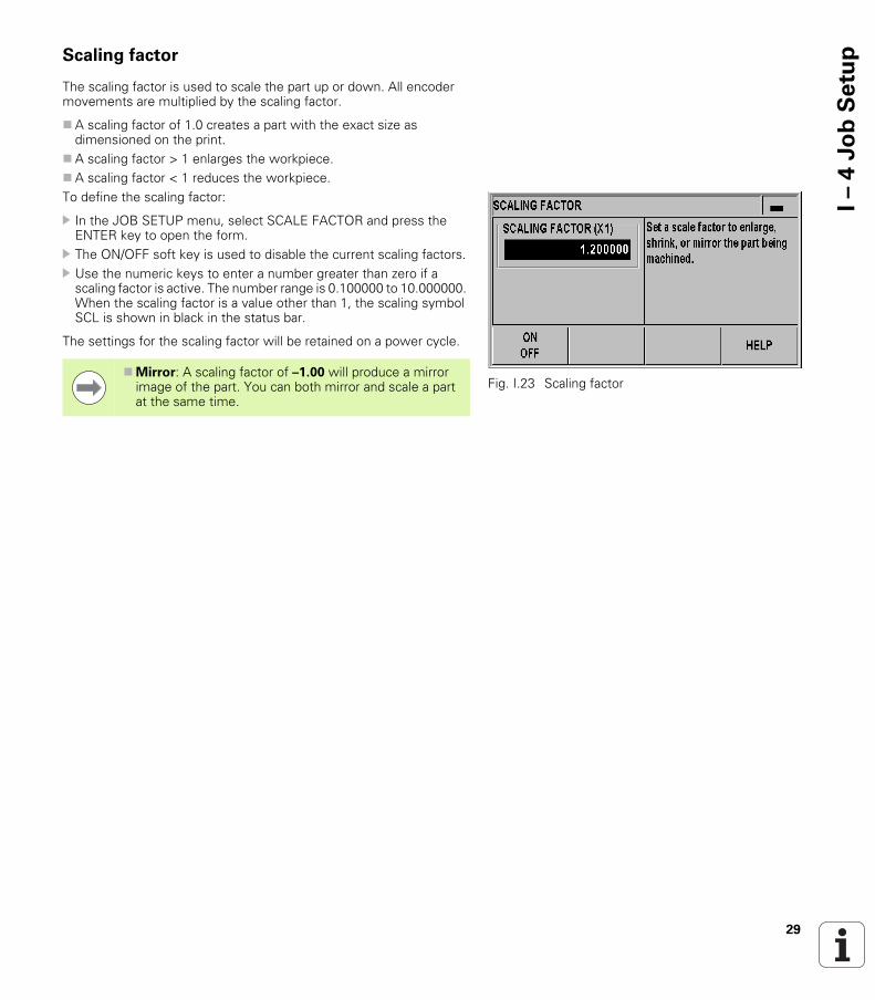
pScaling factor
The scaling factor is used to scale the part up or down. All encoder movements are multiplied by the scaling factor.
A scaling factor of 1.0 creates a part with the exact size as dimensioned on the print.
A scaling factor > 1 enlarges the workpiece.A scaling factor < 1 reduces the workpiece.To define the scaling factor:
In the JOB SETUP menu, select SCALE FACTOR and press the ENTER key to open the form.
The ON/OFF soft key is used to disable the current scaling factors. Use the numeric keys to enter a number greater than zero if a
scaling factor is active. The number range is 0.100000 to 10.000000. When the scaling factor is a value other than 1, the scaling symbol SCL is shown in black in the status bar.
The settings for the scaling factor will be retained on a power cycle.
Fig. I.23 Scaling factorMirror: A scaling factor of –1.00 will produce a mirror
image of the part. You can both mirror and scale a part at the same time.
30 I Working with the ND 280 position display unit
I – 4
Jo
b S
etu
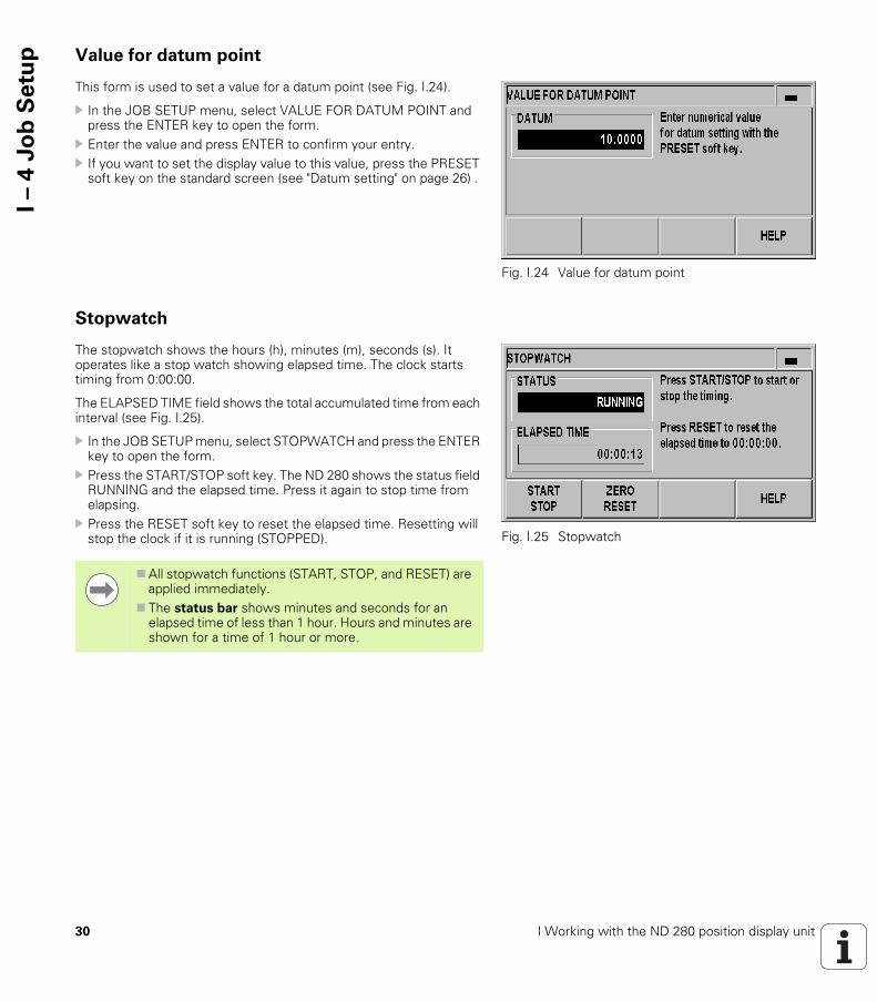
p Value for datum point
This form is used to set a value for a datum point (see Fig. I.24).
In the JOB SETUP menu, select VALUE FOR DATUM POINT and press the ENTER key to open the form.
Enter the value and press ENTER to confirm your entry. If you want to set the display value to this value, press the PRESET
soft key on the standard screen (see "Datum setting" on page 26) .
Stopwatch
The stopwatch shows the hours (h), minutes (m), seconds (s). It operates like a stop watch showing elapsed time. The clock starts timing from 0:00:00.
The ELAPSED TIME field shows the total accumulated time from each interval (see Fig. I.25).
In the JOB SETUP menu, select STOPWATCH and press the ENTER key to open the form.
Press the START/STOP soft key. The ND 280 shows the status field RUNNING and the elapsed time. Press it again to stop time from elapsing.
Press the RESET soft key to reset the elapsed time. Resetting will stop the clock if it is running (STOPPED).
Fig. I.24 Value for datum point
Fig. I.25 Stopwatch
All stopwatch functions (START, STOP, and RESET) are applied immediately.
The status bar shows minutes and seconds for an elapsed time of less than 1 hour. Hours and minutes are shown for a time of 1 hour or more.
31
I – 4
Jo
b S
etu
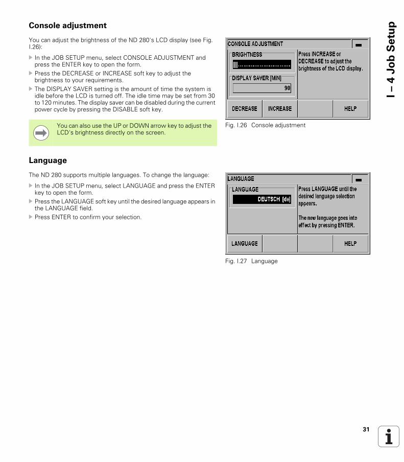
pConsole adjustment
You can adjust the brightness of the ND 280's LCD display (see Fig. I.26):
In the JOB SETUP menu, select CONSOLE ADJUSTMENT and press the ENTER key to open the form.
Press the DECREASE or INCREASE soft key to adjust the brightness to your requirements.
The DISPLAY SAVER setting is the amount of time the system is idle before the LCD is turned off. The idle time may be set from 30 to 120 minutes. The display saver can be disabled during the current power cycle by pressing the DISABLE soft key.
Language
The ND 280 supports multiple languages. To change the language:
In the JOB SETUP menu, select LANGUAGE and press the ENTER key to open the form.
Press the LANGUAGE soft key until the desired language appears in the LANGUAGE field.
Press ENTER to confirm your selection.
Fig. I.26 Console adjustment You can also use the UP or DOWN arrow key to adjust the LCD's brightness directly on the screen.
Fig. I.27 Language
32 I Working with the ND 280 position display unit
I – 5
Err
or
me
ssa
ge
s I – 5 Error messages
Overview
Various error messages may occur while you're using the ND 280. The ND 280 always stores the last error of each error category. You can acknowledge the error messages by pressing the C key,
The following overview will help you to diagnose the errors as quickly as possible:
If a new error occurs before the last error has been acknowledged, the last error that has occurred will be displayed. After you have acknowledged the last error, the previous error will be displayed again. The ND always stores the last error of each error category for acknowledgment.
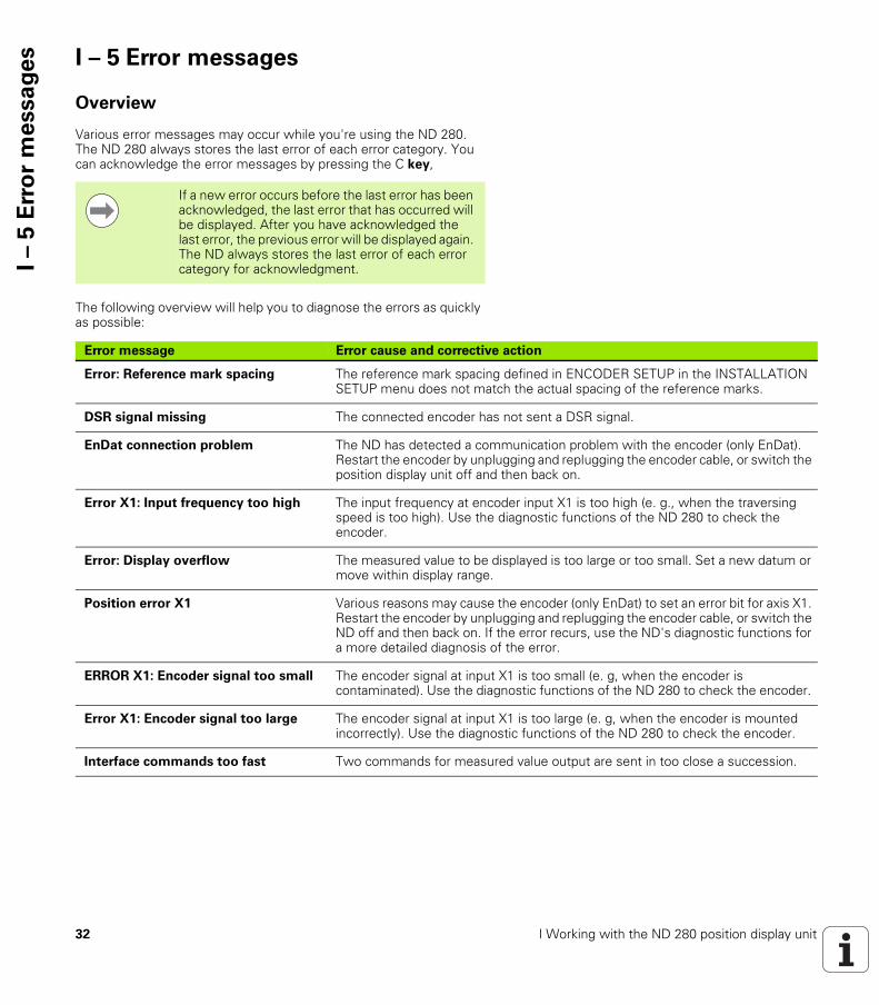
Error message Error cause and corrective action
Error: Reference mark spacing The reference mark spacing defined in ENCODER SETUP in the INSTALLATION SETUP menu does not match the actual spacing of the reference marks.
DSR signal missing The connected encoder has not sent a DSR signal.
EnDat connection problem The ND has detected a communication problem with the encoder (only EnDat). Restart the encoder by unplugging and replugging the encoder cable, or switch the position display unit off and then back on.
Error X1: Input frequency too high The input frequency at encoder input X1 is too high (e. g., when the traversing speed is too high). Use the diagnostic functions of the ND 280 to check the encoder.
Error: Display overflow The measured value to be displayed is too large or too small. Set a new datum or move within display range.
Position error X1 Various reasons may cause the encoder (only EnDat) to set an error bit for axis X1. Restart the encoder by unplugging and replugging the encoder cable, or switch the ND off and then back on. If the error recurs, use the ND's diagnostic functions for a more detailed diagnosis of the error.
ERROR X1: Encoder signal too small The encoder signal at input X1 is too small (e. g, when the encoder is contaminated). Use the diagnostic functions of the ND 280 to check the encoder.
Error X1: Encoder signal too large The encoder signal at input X1 is too large (e. g, when the encoder is mounted incorrectly). Use the diagnostic functions of the ND 280 to check the encoder.
Interface commands too fast Two commands for measured value output are sent in too close a succession.

ND 280 33
Installation,
specifications
34 II Installation, specifications
II –
1 I
nsta
lla
tio
n a
nd
ele
ctr
ica
l co
nn
ecti
on II – 1 Installation and electrical
connection
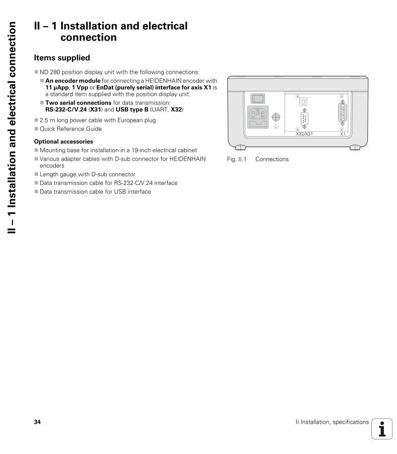
Items supplied
ND 280 position display unit with the following connections:An encoder module for connecting a HEIDENHAIN encoder with
11 µApp, 1 Vpp or EnDat (purely serial) interface for axis X1 is a standard item supplied with the position display unit.
Two serial connections for data transmission: RS-232-C/V.24 (X31) and USB type B (UART, X32)
2.5 m long power cable with European plugQuick Reference Guide
Optional accessories
Mounting base for installation in a 19-inch electrical cabinet Various adapter cables with D-sub connector for HEIDENHAIN
encoders Length gauge with D-sub connectorData transmission cable for RS-232-C/V.24 interfaceData transmission cable for USB interface
Fig. II.1 Connections
���������
ND 280 35
II –
1 I
nsta
lla
tio
n a
nd
ele
ctr
ica
l co
nn
ecti
onMounting
Environmental conditions
Mounting location
Locate the ND 280 in a well ventilated area such that it may be easily accessed during normal operation.
ND 280 – Mounting and installation
M4 screws are used to secure the ND 280 from below. For the hole locations, see "Dimensions" on Page 88.
You can install the ND 280 in an electrical cabinet (see "Mounting base for installation in 19-inch electrical cabinet" on page 90) by using a mounting base (option). The dimensions of the position display unit allow you to install two units next to each other in a 19-inch cabinet (see "Dimensions" on page 88).
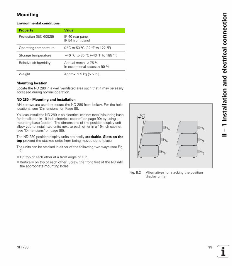
The ND 280 position display units are easily stackable. Slots on the top prevent the stacked units from being moved out of place.
The units can be stacked in either of the following two ways (see Fig. II.2):
On top of each other at a front angle of 10°. Vertically on top of each other: Screw the front feet of the ND into
the appropriate mounting holes.
Property Value
Protection (IEC 60529) IP 40 rear panelIP 54 front panel
Operating temperature 0 °C to 50 °C (32 °F to 122 °F)
Storage temperature –40 °C to 85 °C (–40 °F to 185 °F)
Relative air humidity Annual mean: < 75 %In exceptional cases: < 90 %
Weight Approx. 2.5 kg (5.5 lb.)
Fig. II.2 Alternatives for stacking the position display units
��

36 II Installation, specifications
II –
1 I
nsta
lla
tio
n a
nd
ele
ctr
ica
l co
nn
ecti
on Electromagnetic compatibility/
CE compliance
The ND 280 fulfills the requirements for electromagnetic compatibility according to 2004/108/EC with respect to the generic standards for
Noise immunity as per IEC 61000-6-2: Specifically: ESD as per IEC 61000-4-2 Electromagnetic fields as per IEC 61000-4-3Burst as per IEC 61000-4-4 Surge as per IEC 61000-4-5Conducted disturbances as per IEC 61000-4-6
Emission as per IEC 61000-6-4: Specifically: For industrial, scientific and medical (ISM) equipment as per
EN 55011 For information technology equipment as per IEC 55022 Class B

ND 280 37
II –
1 I
nsta
lla
tio
n a
nd
ele
ctr
ica
l co
nn
ecti
onElectrical connection
Electrical requirements
Wiring the power connector
The ND features a plug socket for a cable with European plug on the rear panel, see Fig. II.3:
Grounding
Fig. II.3 Wiring the power connector
Fig. II.4 Power connection and protective ground terminal on the rear panel
� �
Danger of electrical shock!
Disengage the power plug before opening the unit!
Connect a protective ground (see "Grounding" on page 37).
The protective ground connection must never be interrupted.
Danger to internal components!
Do not engage or disengage any connecting elements while the unit is under power!
Use only original replacement fuses.
Type Value
AC voltage Between 100 and 240 V~
Power Max. 30 W
Frequency 50/60 Hz
Fuse 2 x T500 mA
Hot leads: L and NGround:
Minimum diameter of power connection cable:
0.75 mm2
Maximum cable length: 3 m
Danger to internal components!
It is necessary to connect the ground terminal on the rear panel to the star point of machine ground.
Minimum cross-section of the connecting wire: 6 mm2, see Fig. II.4.
38 II Installation, specifications
II –
1 I
nsta
lla
tio
n a
nd
ele
ctr
ica
l co
nn
ecti
on Preventative maintenance or repair
No special preventative maintenance is necessary. For cleaning, wipe lightly with a dry lint-free cloth.
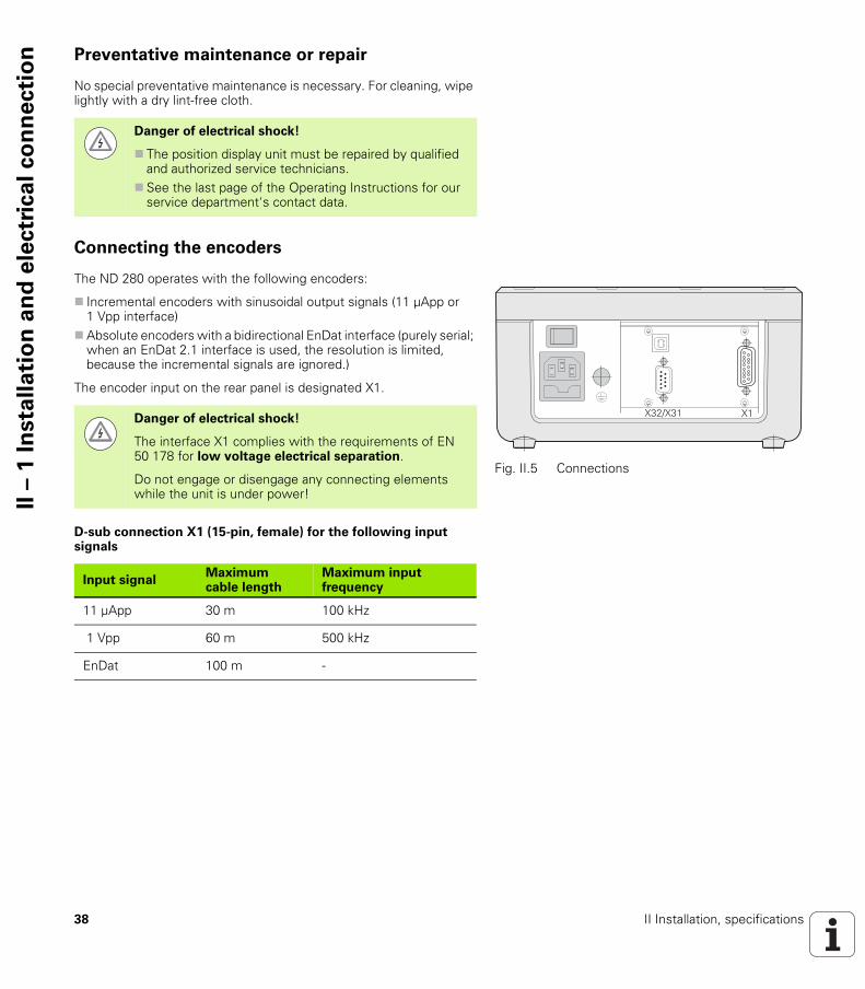
Connecting the encoders
The ND 280 operates with the following encoders:
Incremental encoders with sinusoidal output signals (11 µApp or 1 Vpp interface)
Absolute encoders with a bidirectional EnDat interface (purely serial; when an EnDat 2.1 interface is used, the resolution is limited, because the incremental signals are ignored.)
The encoder input on the rear panel is designated X1.
D-sub connection X1 (15-pin, female) for the following input signals
Danger of electrical shock!
The position display unit must be repaired by qualified and authorized service technicians.
See the last page of the Operating Instructions for our service department's contact data.
Fig. II.5 Connections
���������Danger of electrical shock!
The interface X1 complies with the requirements of EN 50 178 for low voltage electrical separation.
Do not engage or disengage any connecting elements while the unit is under power!
Input signalMaximum cable length
Maximum input frequency
11 µApp 30 m 100 kHz
1 Vpp 60 m 500 kHz
EnDat 100 m -
ND 280 39
II –
1 I
nsta
lla
tio
n a
nd
ele
ctr
ica
l co
nn
ecti
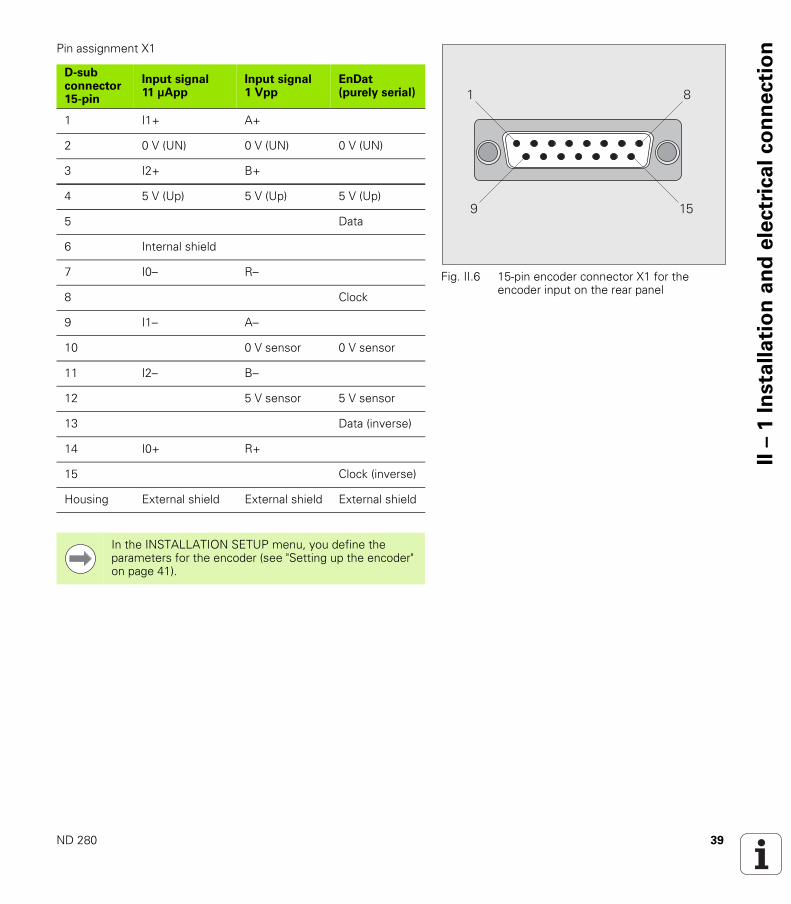
onPin assignment X1
Fig. II.6 15-pin encoder connector X1 for the encoder input on the rear panel
� �
��
D-sub connector 15-pin
Input signal11 µApp
Input signal1 Vpp
EnDat (purely serial)
1 I1+ A+
2 0 V (UN) 0 V (UN) 0 V (UN)
3 I2+ B+
4 5 V (Up) 5 V (Up) 5 V (Up)
5 Data
6 Internal shield
7 I0– R–
8 Clock
9 I1– A–
10 0 V sensor 0 V sensor
11 I2– B–
12 5 V sensor 5 V sensor
13 Data (inverse)
14 I0+ R+
15 Clock (inverse)
Housing External shield External shield External shield
In the INSTALLATION SETUP menu, you define the parameters for the encoder (see "Setting up the encoder" on page 41).

40 II Installation, specifications
II –
2 I
nsta
lla
tio
n S
etu
p II – 2 Installation Setup
INSTALLATION SETUP menu
The ND 280 offers two categories for setting up operating parameters: JOB SETUP and INSTALLATION SETUP.
The JOB SETUP parameters are used to accommodate specific machining requirements for each job, see "Job Setup" on page 25.
The INSTALLATION SETUP menu is used to establish encoder, display and communication parameters.
To call the INSTALLATION SETUP menu:
Begin by pressing the SETUP soft key. This opens the JOB SETUP menu.
Press the INSTALLATION SETUP soft key. Use the numeric keys to enter the correct passcode (95148) and
then press ENTER.
INSTALLATION SETUP parameters are established during the initial installation and, most likely, will not often change. For this reason, the INSTALLATION SETUP parameters are protected by a passcode.
When in the INSTALLATION SETUP menu, the following soft keys will be available (see Fig. II.7):
JOB SETUPPress to begin accessing the JOB SETUP parameters (see "Job Setup" on page 25).
IMPORT/EXPORTPress this soft key to call the IMPORT or EXPORT soft keys for transmitting the operating parameters (see "Serial data transfer with the Import or Export function" on page 62).
HELPThis soft key will open on-line help.
Press the NAVIGATION key to move through the pages of menu parameters. To view and change menu parameters, use the UP/DOWN arrow key to highlight the parameter of interest and press the ENTER key.
On the following pages you will find more information on the menu parameters.
Fig. II.7 INSTALLATION SETUP menu
Once you enter the passcode, it will not have to be entered again until you cycle power.
ND 280 41
II –
2 I
nsta
lla
tio
n S
etu
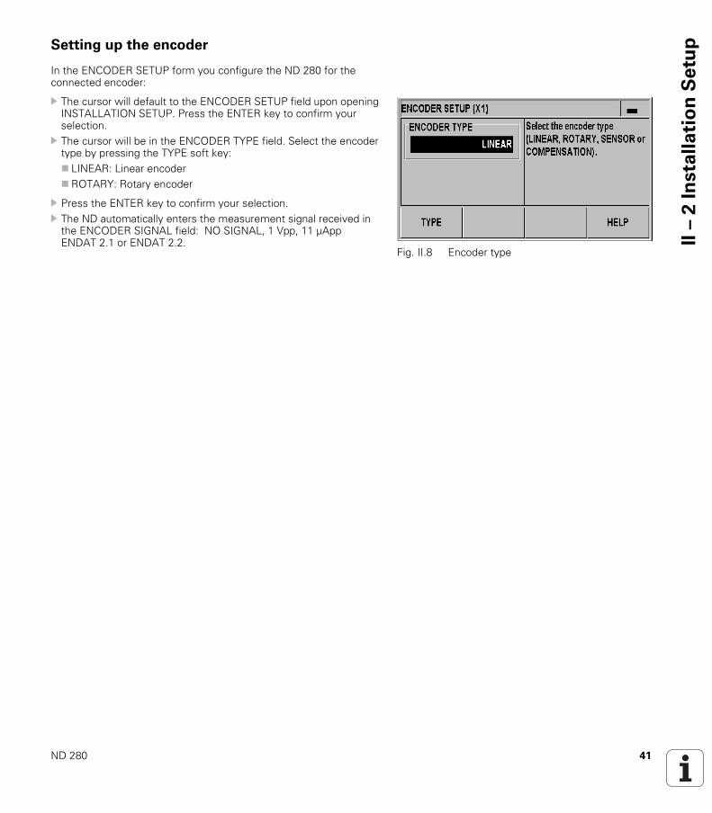
pSetting up the encoder
In the ENCODER SETUP form you configure the ND 280 for the connected encoder:
The cursor will default to the ENCODER SETUP field upon opening INSTALLATION SETUP. Press the ENTER key to confirm your selection.
The cursor will be in the ENCODER TYPE field. Select the encoder type by pressing the TYPE soft key: LINEAR: Linear encoderROTARY: Rotary encoder
Press the ENTER key to confirm your selection. The ND automatically enters the measurement signal received in
the ENCODER SIGNAL field: NO SIGNAL, 1 Vpp, 11 µApp ENDAT 2.1 or ENDAT 2.2.
Fig. II.8 Encoder type
42 II Installation, specifications
II –
2 I
nsta
lla
tio
n S
etu
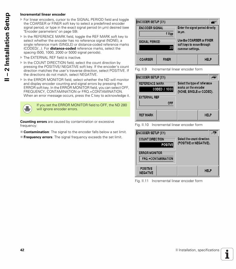
p Incremental linear encoder
For linear encoders, cursor to the SIGNAL PERIOD field and toggle the COARSER or FINER soft key to select a predefined encoder signal period, or type in the exact signal period (in µm) desired (see "Encoder parameters" on page 59).
In the REFERENCE MARK field, toggle the REF MARK soft key to select whether the encoder has no reference signal (NONE), a single reference mark (SINGLE) or distance-coded reference marks (CODED/...). For distance-coded reference marks, select the spacing (500, 1000, 2000 or 5000 signal periods).
The EXTERNAL REF field is inactive. In the COUNT DIRECTION field, select the count direction by
pressing the POSITIVE/ NEGATIVE soft key. If the encoder's count direction matches the user's traverse direction, select POSITIVE. If the directions do not match, select NEGATIVE.
In the ERROR MONITOR field, select whether the ND will monitor and display encoder counting and signal errors by pressing the ERROR soft key. In the ERROR MONITOR field, you can select OFF, FREQUENCY, CONTAMINATION or FRQ.+CONTAMINATION. When an error message occurs, press the C key to acknowledge it.
Counting errors are caused by contamination or excessive frequency:
Contamination: The signal to the encoder falls below a set limit. Frequency errors: The signal frequency exceeds the set limit.
Fig. II.9 Incremental linear encoder form
Fig. II.10 Incremental linear encoder form
Fig. II.11 Incremental linear encoder form
If you set the ERROR MONITOR field to OFF, the ND 280 will ignore encoder errors.
ND 280 43
II –
2 I
nsta
lla
tio
n S
etu
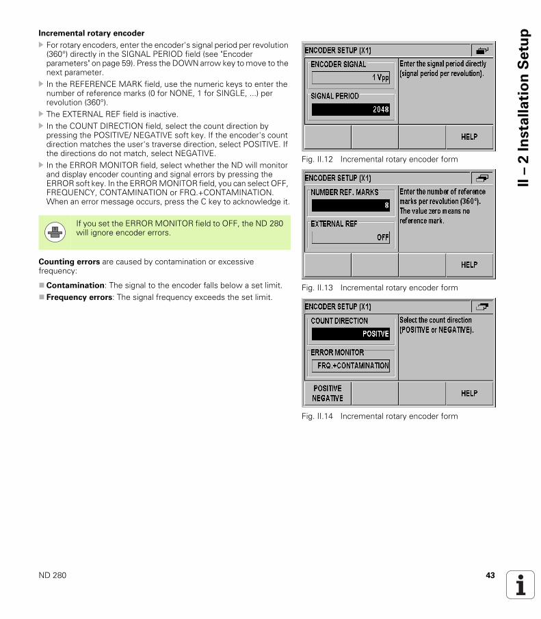
pIncremental rotary encoder
For rotary encoders, enter the encoder's signal period per revolution (360°) directly in the SIGNAL PERIOD field (see "Encoder parameters" on page 59). Press the DOWN arrow key to move to the next parameter.
In the REFERENCE MARK field, use the numeric keys to enter the number of reference marks (0 for NONE, 1 for SINGLE, ...) per revolution (360°).
The EXTERNAL REF field is inactive. In the COUNT DIRECTION field, select the count direction by
pressing the POSITIVE/ NEGATIVE soft key. If the encoder's count direction matches the user's traverse direction, select POSITIVE. If the directions do not match, select NEGATIVE.
In the ERROR MONITOR field, select whether the ND will monitor and display encoder counting and signal errors by pressing the ERROR soft key. In the ERROR MONITOR field, you can select OFF, FREQUENCY, CONTAMINATION or FRQ.+CONTAMINATION. When an error message occurs, press the C key to acknowledge it.
Counting errors are caused by contamination or excessive frequency:
Contamination: The signal to the encoder falls below a set limit. Frequency errors: The signal frequency exceeds the set limit.
Fig. II.12 Incremental rotary encoder form
Fig. II.13 Incremental rotary encoder form
Fig. II.14 Incremental rotary encoder form
If you set the ERROR MONITOR field to OFF, the ND 280 will ignore encoder errors.
44 II Installation, specifications
II –
2 I
nsta
lla
tio
n S
etu
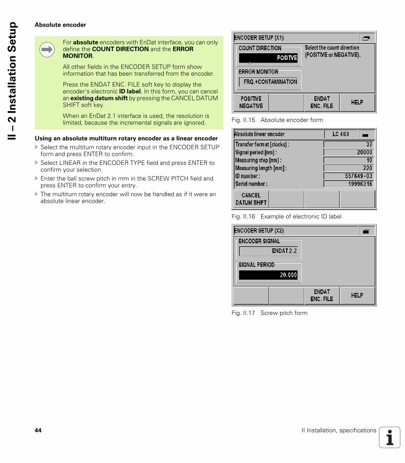
p Absolute encoder
Using an absolute multiturn rotary encoder as a linear encoder
Select the multiturn rotary encoder input in the ENCODER SETUP form and press ENTER to confirm.
Select LINEAR in the ENCODER TYPE field and press ENTER to confirm your selection.
Enter the ball screw pitch in mm in the SCREW PITCH field and press ENTER to confirm your entry.
The multiturn rotary encoder will now be handled as if it were an absolute linear encoder.
Fig. II.15 Absolute encoder form
Fig. II.16 Example of electronic ID label
Fig. II.17 Screw pitch form
For absolute encoders with EnDat interface, you can only define the COUNT DIRECTION and the ERROR MONITOR.
All other fields in the ENCODER SETUP form show information that has been transferred from the encoder.
Press the ENDAT ENC. FILE soft key to display the encoder's electronic ID label. In this form, you can cancel an existing datum shift by pressing the CANCEL DATUM SHIFT soft key.
When an EnDat 2.1 interface is used, the resolution is limited, because the incremental signals are ignored.

ND 280 45
II –
2 I
nsta
lla
tio
n S
etu
pConfiguring the display
In the DISPLAY CONFIGURATION form you determine the display resolution for the different encoders.
In the INSTALLATION SETUP menu, select DISPLAY CONFIGURATION.
Linear encoder
Press the COARSER or FINER soft key to select the display resolution for the axis display in the DISPL. RESOLUTION X1 field.
Rotary encoder
Press the COARSER or FINER soft key to select the display resolution for the axis display in the DISPL. RESOLUTION X1 field.
In the ANGLE DISPLAY field, press the ANGLE soft key to choose between the three following angle formats: +/– 180 DEGREES 360 DEGREES +/– INFINITE
Fig. II.18 DISPLAY CONFIGURATION form for linear encoder
Fig. II.19 DISPLAY CONFIGURATION form for rotary encoder
The selectable display resolution depends on the signal period. The smallest selectable display resolution corresponds to the rounded-off value calculated from dividing the signal period by 4096. For linear encoders, resolutions from 0.5 mm to 0.001 µm are possible, and for rotary encoders from 0.5° to 0.000001° (00°00'00.1").

46 II Installation, specifications
II –
2 I
nsta
lla
tio
n S
etu
p Counter settings
In the COUNTER SETTINGS form, you define the user application for the position display unit (see Fig. II.20):
In the INSTALLATION SETUP menu, select COUNTER SETTINGS. The APPLICATION field shows that you have configured the ND for
one axis. In the KEYBOARD field, use the KEYPAD soft key to release/lock
the keypad. To release the locked keypad, press and hold the NAVIGATION key for at least three seconds. Then enter the password (246584) for releasing the keypad and confirm your entry by pressing the ENTER key, or cancel by pressing the C key.
Press the DOWN arrow key to move to the next parameter. Press the SECOND DEC. POINT soft key to display a second
decimal point after 1/1000 inches (mm). Press the POWER UP SCREEN soft key to define whether the ND
displays the initial screen after it has been switched on. Press the DOWN arrow key to move to the next parameter. The DISPLAY UNIT field shows the type of position display. The SOFTWARE VERSION field shows the currently installed
software version and its identification number. To update your software version, see "Software update (firmware update) installation" on page 64.
The FACTORY DEFAULTS soft key resets the configuration parameters to factory defaults. Press the ENTER key to confirm, or press the C key to cancel.
Fig. II.20 COUNTER SETTINGS
form
Fig. II.21 COUNTER SETTINGS
form
Fig. II.22 COUNTER SETTINGS
form

ND 280 47
II –
2 I
nsta
lla
tio
n S
etu
pError compensation
The distance a cutting tool travels, measured by an encoder, can in certain cases, differ from the actual tool travel. This error can occur due to ball screw pitch error or deflection and tilting of axes.
This error can either be linear or non-linear. You can determine these errors with a reference measurement system, e.g. the VM 101 from HEIDENHAIN. From an analysis of the error it can be determined which form of compensation is required (linear or non-linear).
The ND 280 can compensate these errors.
Only non-linear error compensation is available when using rotary encoders.

48 II Installation, specifications
II –
2 I
nsta
lla
tio
n S
etu
p Linear error compensation (not for rotary encoders)
Linear error compensation can be applied if the results of the comparison with a reference standard show a linear deviation over the whole measuring length. In this case the ND 280 can compensate the error mathematically by calculating the LEC correction factor.
To calculate the linear correction factor, use the following formula:
Example:
If the length of the standard you used is 500 mm and the measured length along the X axis is 499.95 mm, then the LEC for the X axis is 100 ppm:
Entering linear error compensation
In the INSTALLATION SETUP menu, select ERROR COMPENSATION.
Press the ERROR COMP. soft key to select the desired type of compensation. If you select OFF, no error compensation will be applied.
0.0 PPM: Use the numerical keys to enter the linear correction factor in ppm.NONLINEAR (see "Non-linear error compensation" on page 49).
Press ENTER to confirm your entries.
S: length measured with reference standardM: measured length with device at axisppm: parts per million
1 ppm = 10-6= 1 µm/m = 1 µinch/inch
LEC S M–M
------------------ 10
6× ppm=
LEC 500 499 95,( )–499 95,
------------------------------------------------ 10
6× ppm 100ppm= =
Fig. II.23 Linear error compensation form

ND 280 49
II –
2 I
nsta
lla
tio
n S
etu
pNon-linear error compensation
Non-linear error compensation should be applied if the results of the comparison with a reference standard show an alternating or oscillating deviation. The ND 280 supports up to 200 correction points per axis. The error value between two entered adjacent correction points is calculated with linear interpolation. The required correction values must be calculated and entered in an error compensation table.
For rotary encoders, 180 correction points spaced every 2° are predefined by the ND 280.
Selecting non-linear error compensation
In the INSTALLATION SETUP menu, select ERROR COMPENSATION.
Press the ERROR COMP. soft key to select NON-LINEAR.
Non-linear error compensation is available for encoders with reference marks and for absolute encoders.
If non-linear error compensation has been defined, no error compensation will be applied until the reference marks have been crossed.
Fig. II.24 Non-linear error compensation form
50 II Installation, specifications
II –
2 I
nsta
lla
tio
n S
etu
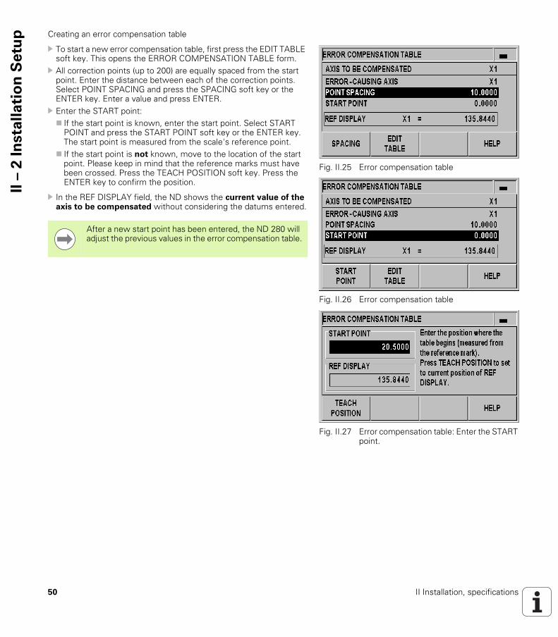
p Creating an error compensation table
To start a new error compensation table, first press the EDIT TABLE soft key. This opens the ERROR COMPENSATION TABLE form.
All correction points (up to 200) are equally spaced from the start point. Enter the distance between each of the correction points. Select POINT SPACING and press the SPACING soft key or the ENTER key. Enter a value and press ENTER.
Enter the START point: If the start point is known, enter the start point. Select START
POINT and press the START POINT soft key or the ENTER key. The start point is measured from the scale's reference point.
If the start point is not known, move to the location of the start point. Please keep in mind that the reference marks must have been crossed. Press the TEACH POSITION soft key. Press the ENTER key to confirm the position.
In the REF DISPLAY field, the ND shows the current value of the axis to be compensated without considering the datums entered.
Fig. II.25 Error compensation table
Fig. II.26 Error compensation table
Fig. II.27 Error compensation table: Enter the START point.
After a new start point has been entered, the ND 280 will adjust the previous values in the error compensation table.
ND 280 51
II –
2 I
nsta
lla
tio
n S
etu
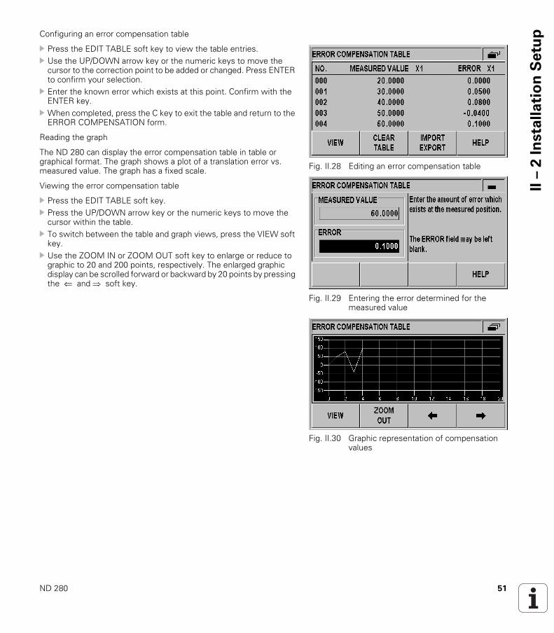
pConfiguring an error compensation table
Press the EDIT TABLE soft key to view the table entries. Use the UP/DOWN arrow key or the numeric keys to move the
cursor to the correction point to be added or changed. Press ENTER to confirm your selection.
Enter the known error which exists at this point. Confirm with the ENTER key.
When completed, press the C key to exit the table and return to the ERROR COMPENSATION form.
Reading the graph
The ND 280 can display the error compensation table in table or graphical format. The graph shows a plot of a translation error vs. measured value. The graph has a fixed scale.
Viewing the error compensation table
Press the EDIT TABLE soft key. Press the UP/DOWN arrow key or the numeric keys to move the
cursor within the table. To switch between the table and graph views, press the VIEW soft
key. Use the ZOOM IN or ZOOM OUT soft key to enlarge or reduce to
graphic to 20 and 200 points, respectively. The enlarged graphic display can be scrolled forward or backward by 20 points by pressing the ⇐ and soft key.
Fig. II.28 Editing an error compensation table
Fig. II.29 Entering the error determined for the measured value
Fig. II.30 Graphic representation of compensation values
52 II Installation, specifications
II –
2 I
nsta
lla
tio
n S
etu
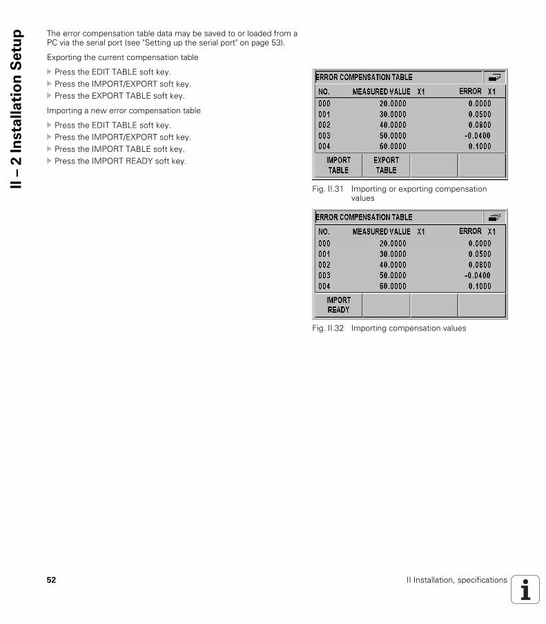
p The error compensation table data may be saved to or loaded from a PC via the serial port (see "Setting up the serial port" on page 53).
Exporting the current compensation table
Press the EDIT TABLE soft key. Press the IMPORT/EXPORT soft key. Press the EXPORT TABLE soft key.
Importing a new error compensation table
Press the EDIT TABLE soft key. Press the IMPORT/EXPORT soft key. Press the IMPORT TABLE soft key. Press the IMPORT READY soft key.
Fig. II.31 Importing or exporting compensation values
Fig. II.32 Importing compensation values
ND 280 53
II –
2 I
nsta
lla
tio
n S
etu
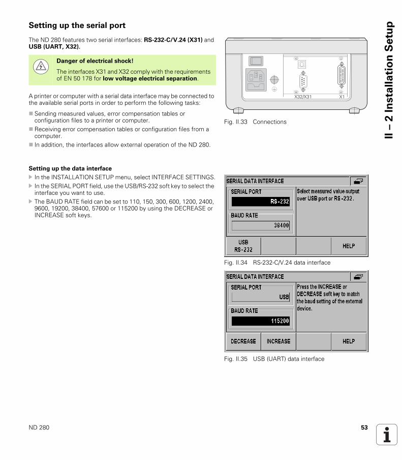
pSetting up the serial port
The ND 280 features two serial interfaces: RS-232-C/V.24 (X31) and USB (UART, X32).
A printer or computer with a serial data interface may be connected to the available serial ports in order to perform the following tasks:
Sending measured values, error compensation tables or configuration files to a printer or computer.
Receiving error compensation tables or configuration files from a computer.
In addition, the interfaces allow external operation of the ND 280.
Setting up the data interface
In the INSTALLATION SETUP menu, select INTERFACE SETTINGS. In the SERIAL PORT field, use the USB/RS-232 soft key to select the
interface you want to use. The BAUD RATE field can be set to 110, 150, 300, 600, 1200, 2400,
9600, 19200, 38400, 57600 or 115200 by using the DECREASE or INCREASE soft keys.
Fig. II.33 Connections
���������
Danger of electrical shock!
The interfaces X31 and X32 comply with the requirements of EN 50 178 for low voltage electrical separation.
Fig. II.34 RS-232-C/V.24 data interface
Fig. II.35 USB (UART) data interface

54 II Installation, specifications
II –
2 I
nsta
lla
tio
n S
etu
p Press the 7/8 soft key to set the DATA BITS field to 7 or 8. Press the 1/2 soft key to set the STOP BITS field to 1 or 2: The PARITY field can be set to NONE, EVEN or ODD using the soft
keys provided. OUTPUT TAIL is the number of carriage returns that will be sent at
the end of the transmission. The output tail is initially 0 and can be set to a positive integer value between 0 and 99 by using the numerical keys.
For information about the cable connection, pin assignment, data input/output and external operation, see "Data interface" on page 61.
The serial port settings will be retained on a power cycle.
Fig. II.36 Data interface: Parameter input
Fig. II.37 Data interface: Parameter input
There is no parameter to enable or disable the serial ports. Data will only be sent to the serial port if the external device is ready.
Data is transferred in the following sequence: Start bit, data bits, parity bit, stop bits.
ND 280 55
II –
2 I
nsta
lla
tio
n S
etu
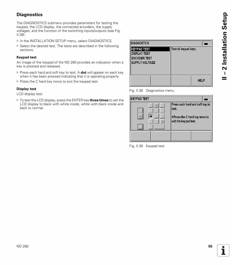
pDiagnostics
The DIAGNOSTICS submenu provides parameters for testing the keypad, the LCD display, the connected encoders, the supply voltages, and the function of the switching inputs/outputs (see Fig. II.38):
In the INSTALLATION SETUP menu, select DIAGNOSTICS. Select the desired test. The tests are described in the following
sections.
Keypad test
An image of the keypad of the ND 280 provides an indication when a key is pressed and released.
Press each hard and soft key to test. A dot will appear on each key when it has been pressed indicating that it is operating properly.
Press the C hard key twice to exit the keypad test.
Display test
LCD display test:
To test the LCD display, press the ENTER key three times to set the LCD display to black with white inside, white with black inside and back to normal.
Fig. II.38 Diagnostics menu
Fig. II.39 Keypad test
56 II Installation, specifications
II –
2 I
nsta
lla
tio
n S
etu
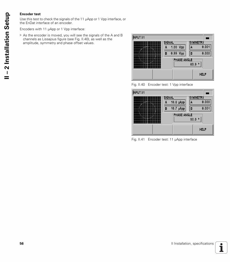
p Encoder test
Use this test to check the signals of the 11 µApp or 1 Vpp interface, or the EnDat interface of an encoder.
Encoders with 11 µApp or 1 Vpp interface:
As the encoder is moved, you will see the signals of the A and B channels as Lissajous figure (see Fig. II.40), as well as the amplitude, symmetry and phase offset values.
Fig. II.40 Encoder test: 1 Vpp interface
Fig. II.41 Encoder test: 11 µApp interface
ND 280 57
II –
2 I
nsta
lla
tio
n S
etu
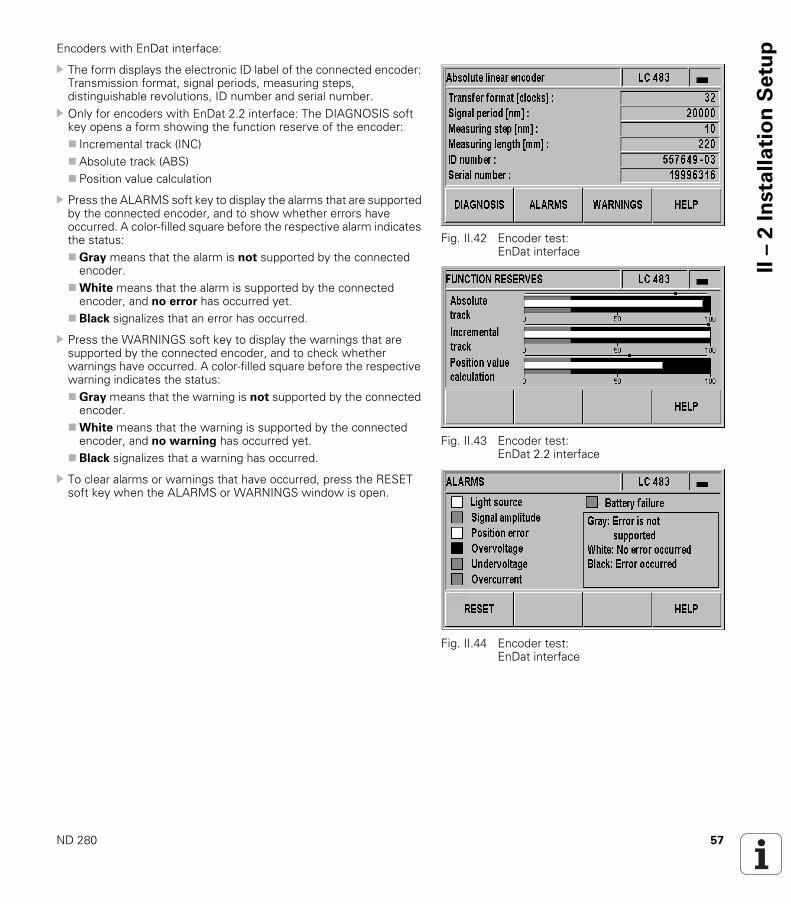
pEncoders with EnDat interface:
The form displays the electronic ID label of the connected encoder: Transmission format, signal periods, measuring steps, distinguishable revolutions, ID number and serial number.
Only for encoders with EnDat 2.2 interface: The DIAGNOSIS soft key opens a form showing the function reserve of the encoder: Incremental track (INC)Absolute track (ABS) Position value calculation
Press the ALARMS soft key to display the alarms that are supported by the connected encoder, and to show whether errors have occurred. A color-filled square before the respective alarm indicates the status:Gray means that the alarm is not supported by the connected
encoder.White means that the alarm is supported by the connected
encoder, and no error has occurred yet.Black signalizes that an error has occurred.
Press the WARNINGS soft key to display the warnings that are supported by the connected encoder, and to check whether warnings have occurred. A color-filled square before the respective warning indicates the status:Gray means that the warning is not supported by the connected
encoder.White means that the warning is supported by the connected
encoder, and no warning has occurred yet.Black signalizes that a warning has occurred.
To clear alarms or warnings that have occurred, press the RESET soft key when the ALARMS or WARNINGS window is open.
Fig. II.42 Encoder test: EnDat interface
Fig. II.43 Encoder test: EnDat 2.2 interface
Fig. II.44 Encoder test: EnDat interface
58 II Installation, specifications
II –
2 I
nsta
lla
tio
n S
etu
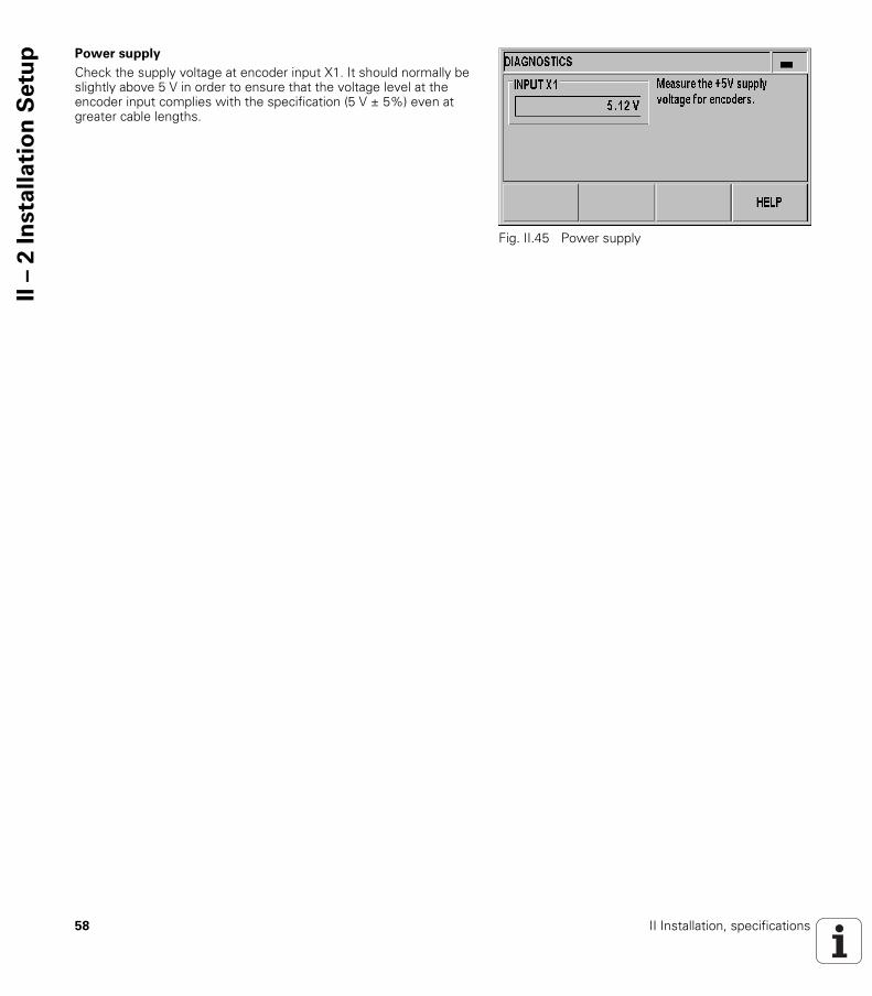
p Power supply
Check the supply voltage at encoder input X1. It should normally be slightly above 5 V in order to ensure that the voltage level at the encoder input complies with the specification (5 V ± 5%) even at greater cable lengths.
Fig. II.45 Power supply

ND 280 59
II –
3 E
nco
de
r p
ara
me
tersII – 3 Encoder parameters
Table values
The following tables represent a partial list of HEIDENHAIN encoders. These tables describe the operating parameters which you must set for the encoders. Most entries can be found in the operating instructions for your encoder.
HEIDENHAIN linear encoders
Encoder Signal period Reference marks
SPECTO ST 12/30 20 µm Single
METRO MT 60/101 10 µm Single
METRO MT 12xx/25xx 2 µm Single
CERTO CT 25xx/60xx 2 µm Single
LS 388C 20 µm Coded/1000
LS 487LS 487C
20 µm SingleCoded/1000
LS 186LS 186C
20 µm SingleCoded/1000
LF 183LF 183C
4 µm SingleCoded/5000
LB 382LB 382C
40 µm SingleCoded/2000
LC 183LC 483
Self-configuring NoneAbsolute
LIDA 18xLIDA 48x
40 µm Single
LIDA 28x 200 µm Single
LIDA 583 20 µm Single
LIF 181RLIF 181C
8 µm SingleCoded/5000
LIF 581RLIF 581C
8 µm SingleCoded/5000

60 II Installation, specifications
II –
3 E
nco
de
r p
ara
me
ters HEIDENHAIN rotary encoders
Encoder Signal period Reference marks
ROD 48xERN x80
1000 ... 5000 Single
ROC 425ECN x25
Self-configuring NoneAbsolute
ROQ 437EQN 437
Self-configuring NoneAbsolute
ROD 280ROD 280C
18000 SingleCoded/36
RON 28xRON 28xC
18000 SingleCoded/36
RON 785RON 785C
18000 SingleCoded/36
RON 886RON 886C
36000 SingleCoded/72
RCN 22x Self-configuring NoneAbsolute
RCN 729RCN 829
Self-configuring NoneAbsolute
ND 280 61
II –
4 D
ata
in
terf
aceII – 4 Data interface
Data communication
The ND 280 features two serial interfaces: RS-232/V.24 (X31) and USB (UART, X32).
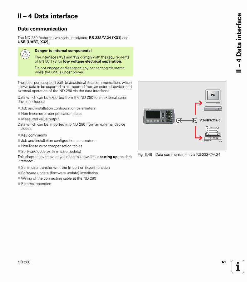
The serial ports support both bi-directional data communication, which allows data to be exported to or imported from an external device, and external operation of the ND 280 via the data interface.
Data which can be exported from the ND 280 to an external serial device includes:
Job and installation configuration parametersNon-linear error compensation tablesMeasured value outputData which can be imported into ND 280 from an external device includes:
Key commands Job and installation configuration parametersNon-linear error compensation tables Software updates (firmware update)This chapter covers what you need to know about setting up the data interface:
Serial data transfer with the Import or Export function Software update (firmware update) installationWiring of the connecting cable at the ND 280 External operation
Danger to internal components!
The interfaces X31 and X32 comply with the requirements of EN 50 178 for low voltage electrical separation.
Do not engage or disengage any connecting elements while the unit is under power!
Fig. II.46 Data communication via RS-232-C/V.24
������������
62 II Installation, specifications
II –
4 D
ata
in
terf
ace Serial data transfer with the Import or Export
function
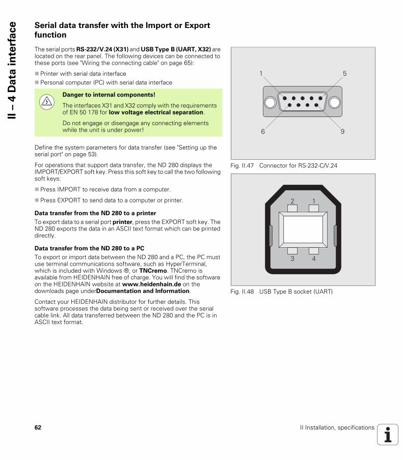
The serial ports RS-232/V.24 (X31) and USB Type B (UART, X32) are located on the rear panel. The following devices can be connected to these ports (see "Wiring the connecting cable" on page 65):
Printer with serial data interface Personal computer (PC) with serial data interface
Define the system parameters for data transfer (see "Setting up the serial port" on page 53).
For operations that support data transfer, the ND 280 displays the IMPORT/EXPORT soft key. Press this soft key to call the two following soft keys:
Press IMPORT to receive data from a computer.
Press EXPORT to send data to a computer or printer.
Data transfer from the ND 280 to a printer
To export data to a serial port printer, press the EXPORT soft key. The ND 280 exports the data in an ASCII text format which can be printed directly.
Data transfer from the ND 280 to a PC
To export or import data between the ND 280 and a PC, the PC must use terminal communications software, such as HyperTerminal, which is included with Windows ®, or TNCremo. TNCremo is available from HEIDENHAIN free of charge. You will find the software on the HEIDENHAIN website at www.heidenhain.de on the downloads page underDocumentation and Information.
Contact your HEIDENHAIN distributor for further details. This software processes the data being sent or received over the serial cable link. All data transferred between the ND 280 and the PC is in ASCII text format.
Fig. II.47 Connector for RS-232-C/V.24
Fig. II.48 USB Type B socket (UART)
� �
�
��
�
Danger to internal components!
The interfaces X31 and X32 comply with the requirements of EN 50 178 for low voltage electrical separation.
Do not engage or disengage any connecting elements while the unit is under power!
ND 280 63
II –
4 D
ata
in
terf
aceTo export data from the ND 280 to a PC, the PC must first be made
ready to receive the data to save it to a file. Set up the terminal communication program to capture ASCII text data from the COM port to a file on the PC. After the PC is ready to receive, start the data transfer by pressing the ND 280's EXPORT soft key.
Importing data into the ND 280 from a PC
To import data into the ND 280 from a PC, the ND 280 must first be made ready to receive the data:
Press the IMPORT soft key. After the ND 280 is ready, set up the terminal communications program on the PC to send the desired file in ASCII text format.
Data format
The data format can be defined in the INSTALLATION SETUP menu under INTERFACE SETTINGS (see "Setting up the serial port" on page 53).
Control characters
For examples of measured value output, refer to "Measured value output" on page 74.
The ND 280 does not support communication protocols such as Kermit or Xmodem.
Measured value retrieval: STX (CTRL B)Interruption: DC3 (CTRL S)Continuation: DC1 (CTRL Q)Error message enquiry: ENQ (CTRL E)
64 II Installation, specifications
II –
4 D
ata
in
terf
ace Software update (firmware update) installation
If required, you can download a software update (firmware update) for your ND from the HEIDENHAIN website. You will find the update at www.heidenhain.de on the downloads page under Documentation and Information.
To install the software update (firmware update):
Connect your PC to the serial port USB Type B (UART, X32), see "Wiring the connecting cable" on page 65.
The device driver must be installed on your PC in order to transmit data over the USB port, see "Wiring the connecting cable" on page 65.
Double-click the file to start the software update (firmware update) on the PC.
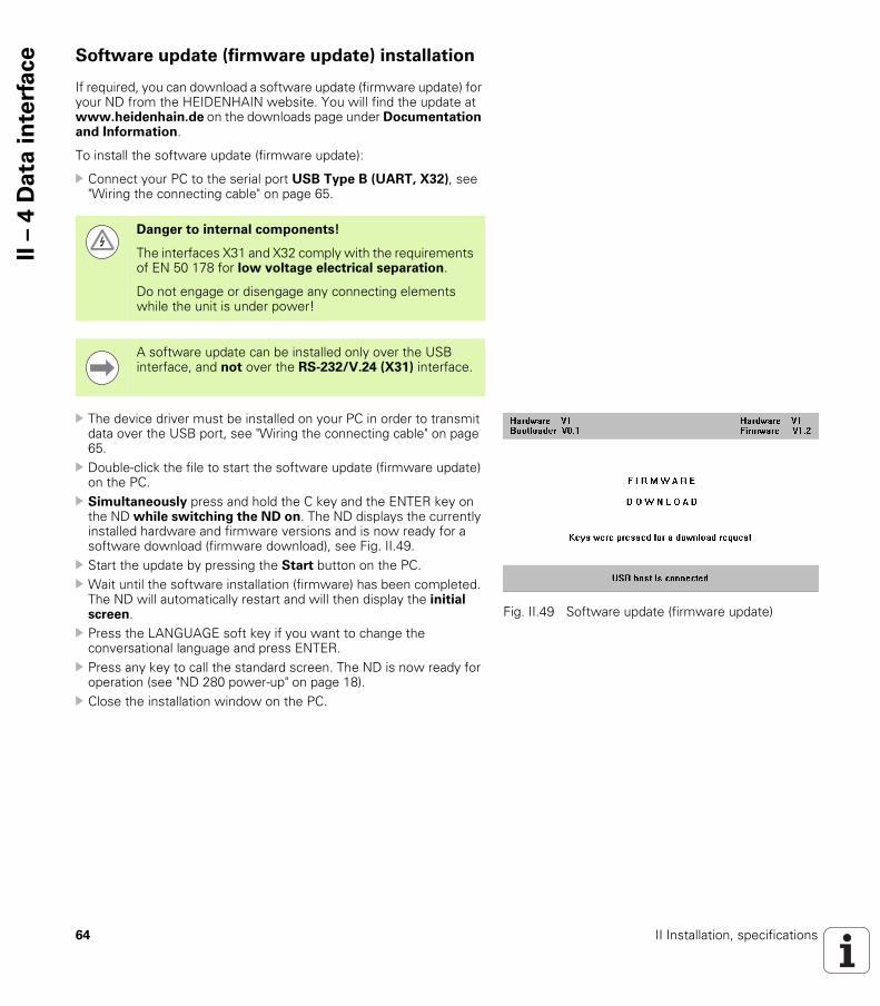
Simultaneously press and hold the C key and the ENTER key on the ND while switching the ND on. The ND displays the currently installed hardware and firmware versions and is now ready for a software download (firmware download), see Fig. II.49.
Start the update by pressing the Start button on the PC. Wait until the software installation (firmware) has been completed.
The ND will automatically restart and will then display the initial screen.
Press the LANGUAGE soft key if you want to change the conversational language and press ENTER.
Press any key to call the standard screen. The ND is now ready for operation (see "ND 280 power-up" on page 18).
Close the installation window on the PC.
Danger to internal components!
The interfaces X31 and X32 comply with the requirements of EN 50 178 for low voltage electrical separation.
Do not engage or disengage any connecting elements while the unit is under power!
A software update can be installed only over the USB interface, and not over the RS-232/V.24 (X31) interface.
Fig. II.49 Software update (firmware update)

ND 280 65
II –
4 D
ata
in
terf
aceWiring the connecting cable
The wiring of the connecting cable depends on the device being connected (see technical documentation for external device).
Complete wiring of RS-232-C/V.24 (X31)
Before the ND 280 and your PC can communicate, they need to be connected to each other with a serial cable.
RS-232-C / V.24 data transfer cableD-sub (female) 9-pin/D-sub (female) 9-pin
ID 366964-xx
Signal level
Fig. II.50 Pin assignment for serial port with handshaking
Fig. II.51 Pin assignment for serial port without handshaking
�����
������
������
�����
������
������
������
������
����
�����
������
������
�����
������
������
������
������
����
������ ��
�����
������
������
�����
������
������
������
������
����
������
������
������
������ ��
Pin Assignment Function
1 Do not assign
3 TXD Transmitted data
2 RXD Received data
7 RTS Request to send
8 CTS Clear to Send
6 DSR Data set ready
5 SIGNAL GND Signal ground
4 DTR Data terminal ready
9 Do not assign
SignalSignal level"1" = "active"
Signal level"0"= "inactive"
TXD, RXD –3 V to –15 V +3 V to +15 V
RTS, CTSDSR, DTR
+3 V to +15 V –3 V to –15 V

66 II Installation, specifications
II –
4 D
ata
in
terf
ace USB Type B (UART), socket as per IEC 61076-3-108
If you want to connect your position display unit to a PC via the USB interface, you need a special USB driver. You will find the driver file for Windows 2000, XP, Vista and 7 in the installation directory of the TNCremo software or on the HEIDENHAIN website at www.heidenhain.de on the downloads page under Documentation and Information.
After downloading the software, run the respective file. Then connect your position display unit to the PC, and switch the position display unit on. Then you can install the USB driver with the Windows hardware wizard, which will start automatically.
Cable length: Max. 5 m
Fig. II.52 Pin assignment USB Type B socket
��
�
Pin Assignment Function
1 VCC +5 V
2 D– Data (inverse)
3 D+ Data
4 GND Signal ground
ND 280 67
II –
4 D
ata
in
terf
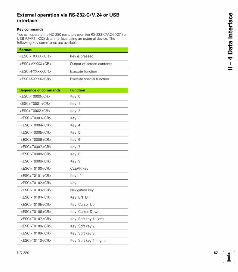
aceExternal operation via RS-232-C/V.24 or USB
interface
Key commands
You can operate the ND 280 remotely over the RS-232-C/V.24 (X31) or USB (UART, X32) data interface using an external device. The following key commands are available:
Format
<ESC>TXXXX<CR> Key is pressed
<ESC>AXXXX<CR> Output of screen contents
<ESC>FXXXX<CR> Execute function
<ESC>SXXXX<CR> Execute special function
Sequence of commands Function
<ESC>T0000<CR> Key '0'
<ESC>T0001<CR> Key '1'
<ESC>T0002<CR> Key '2'
<ESC>T0003<CR> Key '3'
<ESC>T0004<CR> Key '4'
<ESC>T0005<CR> Key '5'
<ESC>T0006<CR> Key '6'
<ESC>T0007<CR> Key '7'
<ESC>T0008<CR> Key '8'
<ESC>T0009<CR> Key '9'
<ESC>T0100<CR> CLEAR key
<ESC>T0101<CR> Key '–'
<ESC>T0102<CR> Key '.'
<ESC>T0103<CR> Navigation key
<ESC>T0104<CR> Key 'ENTER'
<ESC>T0105<CR> Key 'Cursor Up'
<ESC>T0106<CR> Key 'Cursor Down'
<ESC>T0107<CR> Key 'Soft key 1' (left)
<ESC>T0108<CR> Key 'Soft key 2'
<ESC>T0109<CR> Key 'Soft key 3'
<ESC>T0110<CR> Key 'Soft key 4' (right)
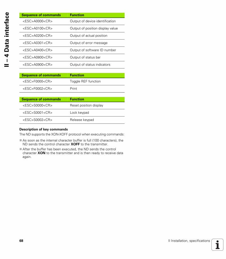
68 II Installation, specifications
II –
4 D
ata
in
terf
ace
Description of key commands
The ND supports the XON-XOFF protocol when executing commands:
As soon as the internal character buffer is full (100 characters), the ND sends the control character XOFF to the transmitter.
After the buffer has been executed, the ND sends the control character XON to the transmitter and is then ready to receive data again.
Sequence of commands Function
<ESC>A0000<CR> Output of device identification
<ESC>A0100<CR> Output of position display value
<ESC>A0200<CR> Output of actual position
<ESC>A0301<CR> Output of error message
<ESC>A0400<CR> Output of software ID number
<ESC>A0800<CR> Output of status bar
<ESC>A0900<CR> Output of status indicators
Sequence of commands Function
<ESC>F0000<CR> Toggle REF function
<ESC>F0002<CR> Print
Sequence of commands Function
<ESC>S0000<CR> Reset position display
<ESC>S0001<CR> Lock keypad
<ESC>S0002<CR> Release keypad

ND 280 69
II –
4 D
ata
in
terf
aceKey is pressed (TXXXX commands)
The ND acknowledges every correctly received key command by transmitting the control character ACK (Acknowledge, CTRL F). Then the ND executes the key command.
The ND responds to commands that cannot be identified or to invalid commands by sending the control character NAK (No acknowledge, CTRL U).
Output of screen contents (AXXXX commands)
The ND responds to valid commands by sending the control character STX (Start of text, CTRL B) before outputting the text.
The ND responds to commands that cannot be identified or to invalid commands by sending the control character NAK (No acknowledge, CTRL U).
Output of device identification:
Device name ID number of the currently installed software Version number of the currently installed software
Output of position display value:
<STX> N D - 2 8 0 <CR> <LF>
6 4 6 1 1 8 - 0 1 <CR> <LF>
V 1 - 0 1 <CR> <LF>
1 2 3
1 STX control character: 1 character2 Device identification: 10 characters3 End of line: 2 characters
<STX> - 1 2 3 4 5 .
6 7 8 9 <CR> <LF>
4 5 6
4 STX control character: 1 character5 Displayed position value: 10 - 13 characters, depending on the number of decimal points and decimal places6 End of line: 2 characters

70 II Installation, specifications
II –
4 D
ata
in
terf
ace Output of current position:
Output of error message:
Output of software ID number:
<STX> + 1 2 3 4 5 6 7 8 9 <CR> <LF>
7 8 9
7 STX control character: 1 character8 Current position: 10 characters, without decimal point, with leading zeros9 End of line: 2 characters
The error text displayed in the message line is transmitted.
This functions only if an error message is displayed.
<STX> E R R O R X 1 : I N P U T F R
E Q U E N C Y T O O H I G H ! <CR> <LF>
10 11 12
10 STX control character: 1 character11 Error message: 35 characters12 End of line: 2 characters
<STX> 6 3 7 4 5 6 - 0 1 <CR> <LF>
13 14 15
13 STX control character: 1 character14 ID number of the currently installed software: 10 characters15 End of line: 2 characters
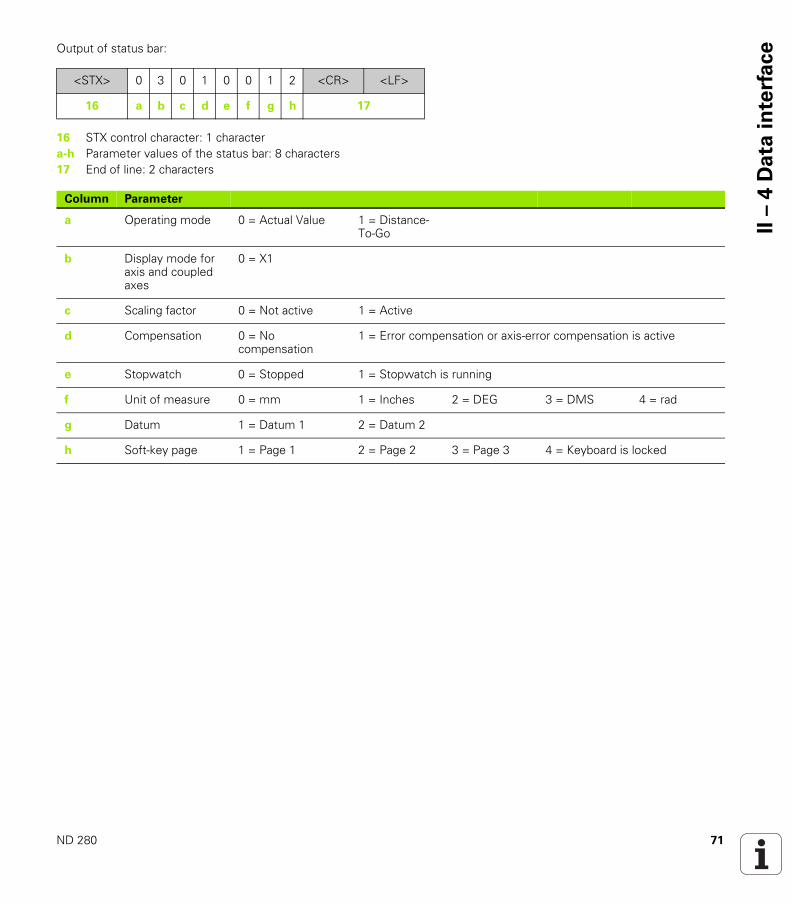
ND 280 71
II –
4 D
ata
in
terf
aceOutput of status bar:
<STX> 0 3 0 1 0 0 1 2 <CR> <LF>
16 a b c d e f g h 17
16 STX control character: 1 charactera-h Parameter values of the status bar: 8 characters17 End of line: 2 characters
Column Parameter
a Operating mode 0 = Actual Value 1 = Distance-To-Go
b Display mode for axis and coupled axes
0 = X1
c Scaling factor 0 = Not active 1 = Active
d Compensation 0 = No compensation
1 = Error compensation or axis-error compensation is active
e Stopwatch 0 = Stopped 1 = Stopwatch is running
f Unit of measure 0 = mm 1 = Inches 2 = DEG 3 = DMS 4 = rad
g Datum 1 = Datum 1 2 = Datum 2
h Soft-key page 1 = Page 1 2 = Page 2 3 = Page 3 4 = Keyboard is locked
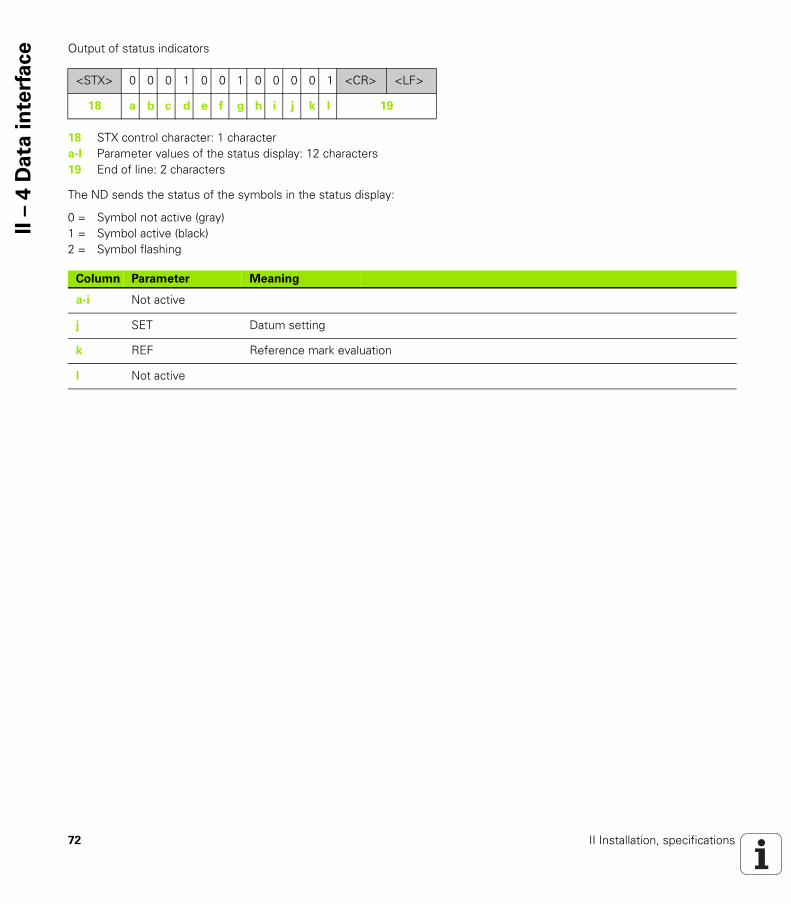
72 II Installation, specifications
II –
4 D
ata
in
terf
ace Output of status indicators
The ND sends the status of the symbols in the status display:
<STX> 0 0 0 1 0 0 1 0 0 0 0 1 <CR> <LF>
18 a b c d e f g h i j k l 19
18 STX control character: 1 charactera-l Parameter values of the status display: 12 characters19 End of line: 2 characters
0 = Symbol not active (gray)1 = Symbol active (black)2 = Symbol flashing
Column Parameter Meaning
a-i Not active
j SET Datum setting
k REF Reference mark evaluation
l Not active
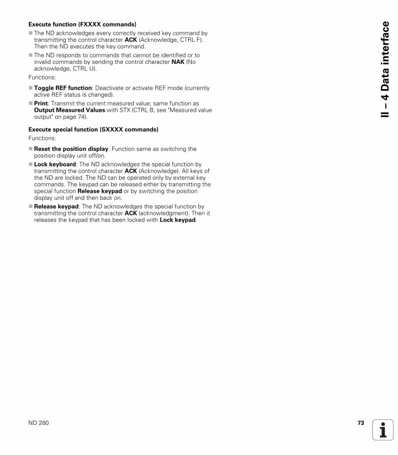
ND 280 73
II –
4 D
ata
in
terf
aceExecute function (FXXXX commands)
The ND acknowledges every correctly received key command by transmitting the control character ACK (Acknowledge, CTRL F). Then the ND executes the key command.
The ND responds to commands that cannot be identified or to invalid commands by sending the control character NAK (No acknowledge, CTRL U).
Functions:
Toggle REF function: Deactivate or activate REF mode (currently active REF status is changed).
Print: Transmit the current measured value; same function as Output Measured Values with STX (CTRL B, see "Measured value output" on page 74).
Execute special function (SXXXX commands)
Functions:
Reset the position display: Function same as switching the position display unit off/on.
Lock keyboard: The ND acknowledges the special function by transmitting the control character ACK (Acknowledge). All keys of the ND are locked. The ND can be operated only by external key commands. The keypad can be released either by transmitting the special function Release keypad or by switching the position display unit off and then back on.
Release keypad: The ND acknowledges the special function by transmitting the control character ACK (acknowledgment). Then it releases the keypad that has been locked with Lock keypad.

74 II Installation, specifications
II –
5 M
ea
su
red
va
lue
ou
tpu
t II – 5 Measured value output
Alternatives for starting measured value output
With a PC, there are two ways to start measured value output from the ND 280: With CTRL B or the PRINT soft key over the serial port X31 or X32.
Measured-value output via the serial data
interface X31 or X32
Use the PRINT soft key or the CTRL B command to transmit the currently displayed values in either Actual Value or Distance-To-Go mode, whichever is currently active (see "Operating modes" on page 25), via either the RS-232-C/V.24 or the USB interface to a PC.
Danger to internal components!
The interfaces X31 and X32 comply with the requirements of EN 50 178 for low voltage electrical separation.
Do not engage or disengage any connecting elements while the unit is under power!

ND 280 75
II –
5 M
ea
su
red
va
lue
ou
tpu
tCTRL B command:
RS-232-C/V.24 interface:If the ND receives the CTRL B command over the RXD line of the interface, it transmits the measured values back over the TXD line (see "Data interface" on page 61).
USB Type B: This interface supports bidirectional data communication. Data transfer is started with the CTRL B command.
Data transfer:
The measured values can be received and saved using a terminal program (e. g. HyperTerminal, which is included with Windows ®). You can also use the TNCremo software. TNCremo is available from HEIDENHAIN free of charge. You will find the software at www.heidenhain.de on the downloads page under Documentation and Information.
The basic program (see Fig. II.53) shows the fundamental structure of a program for measured value output.
Propagation times
Fig. II.53 Basic program for measured value output with CTRL B
Fig. II.54 Propagation times for measured value output after CTRL B
10 L%=1820 CLS30 PRINT "V.24/RS-232-C" 40 OPEN "COM1:9600,E,7" AS#150 PRINT #1, CHR$ (2);60 IF INKEY$<>""THEN 13070 C%=LOC(1)80 IF C%<L%THEN 6090 X$=INPUT$(L%,#1)100 LOCATE 9,1110 PRINT X$;120 GOTO 50130 END
��
��
������
��
��
������Event Time
Latching delay t1 t1 ≤ 1 ms
Measured-value output after t2 t2 ≤ 50 ms
Regeneration time t3 t3 ≥ 0 ms

76 II Installation, specifications
II –
5 M
ea
su
red
va
lue
ou
tpu
t Duration of measured value transfer
Example: Data sequence during measured-value output
Measured value: X = - 5.23 mm
Measured value output:
tD Duration of measured value transfer in [s]L: Number of blank linesB: Baud rate
- 5.23 <CR> <LF>
1 2 3 4 5 6 7 8
1 +/– sign2 Numerical value with decimal point: 10 characters on the whole,
leading zeros are output as blank spaces.3 Blank space4 Unit of measure: Blank space = mm, “= inches, G = degrees,
M = DMS, R = rad, ? = fault5 Blank space6 Blank space7 Carriage return8 Blank line (Line Feed)
tD187 11 L•( )+
B----------------------------=

ND 280 77
II –
6 I
np
ut
an
d o
utp
ut
of
pa
ram
ete
r li
st
an
d e
rro
rco
mp
en
sa
tio
n t
ab
leII – 6 Input and output of parameter list and error compensation table
Text file
You can receive the lists output by the ND via the serial data interface as text files in ASCII format and save them on your PC.
To export or import data between the ND 280 and a PC, the PC must use terminal communications software, such as HyperTerminal, which is included with Windows ®, or TNCremo. TNCremo is available from HEIDENHAIN free of charge. You will find the software at www.heidenhain.de on the downloads page under Documentation and Information.
The lists received are first checked for the type of position display unit (line 2 of output list). The receiving ND accepts only lists prepared by the same type of position display unit. For example, if the ND 280 receives a parameter list from the ND 287, it generates the message "ERROR DURING RECEPTION Incorrect data file." in the window to the right. Acknowledge the message with the C key.
Furthermore, the ND checks the list for completeness. Lists that contain, for example, too many or too few parameters are ignored. If an error occurs, the ND also displays an error message: ERROR DURING RECEPTION Incorrect data file. Acknowledge the error message with the C key.
Example: P01 LINEAR = 3The value 3 is not allowed. The parameter P01 is set to the default setting: P01 LINEAR = 0
Each list must be saved as a separate text file. You can then use the terminal program to transmit the
text files back to the ND. If you want, you can edit the text files with a text editor
and change the parameter values, for example. However, this requires knowledge of the different output formats of the lists (see following pages). When receiving lists, the ND expects the same list structure as used for the output.
When receiving lists, the ND firsts waits for the starting character < # >.
The receiving mode ends as soon as the ND has received the final character < # >.
If the ND receives invalid parameter values, it sets the respective operating parameters to the default settings.
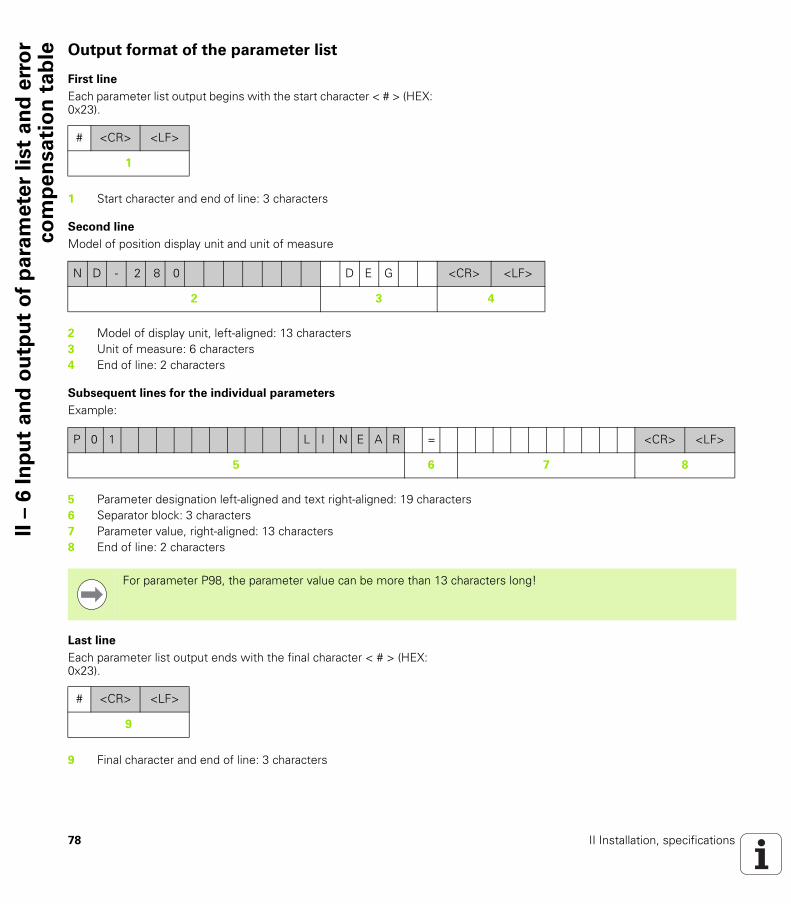
78 II Installation, specifications
II –
6 I
np
ut
an
d o
utp
ut
of
pa
ram
ete
r li
st
an
d e
rro
rco
mp
en
sa
tio
n t
ab
le Output format of the parameter list
First line
Each parameter list output begins with the start character < # > (HEX: 0x23).
Second line
Model of position display unit and unit of measure
Subsequent lines for the individual parameters
Example:
Last line
Each parameter list output ends with the final character < # > (HEX: 0x23).
# <CR> <LF>
1
1 Start character and end of line: 3 characters
N D - 2 8 0 D E G <CR> <LF>
2 3 4
2 Model of display unit, left-aligned: 13 characters3 Unit of measure: 6 characters4 End of line: 2 characters
P 0 1 L I N E A R = <CR> <LF>
5 6 7 8
5 Parameter designation left-aligned and text right-aligned: 19 characters6 Separator block: 3 characters7 Parameter value, right-aligned: 13 characters8 End of line: 2 characters
For parameter P98, the parameter value can be more than 13 characters long!
# <CR> <LF>
9
9 Final character and end of line: 3 characters
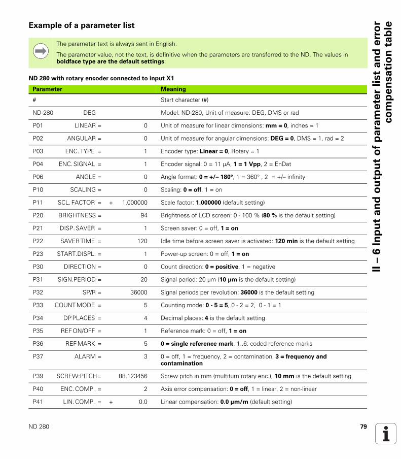
ND 280 79
II –
6 I
np
ut
an
d o
utp
ut
of
pa
ram
ete
r li
st
an
d e
rro
rco
mp
en
sa
tio
n t
ab
leExample of a parameter list
ND 280 with rotary encoder connected to input X1
The parameter text is always sent in English.
The parameter value, not the text, is definitive when the parameters are transferred to the ND. The values in boldface type are the default settings.
Parameter Meaning
# Start character (#)
ND-280 DEG Model: ND-280, Unit of measure: DEG, DMS or rad
P01 LINEAR = 0 Unit of measure for linear dimensions: mm = 0, inches = 1
P02 ANGULAR = 0 Unit of measure for angular dimensions: DEG = 0, DMS = 1, rad = 2
P03 ENC. TYPE = 1 Encoder type: Linear = 0, Rotary = 1
P04 ENC. SIGNAL = 1 Encoder signal: 0 = 11 µA, 1 = 1 Vpp, 2 = EnDat
P06 ANGLE = 0 Angle format: 0 = +/– 180°, 1 = 360° , 2 = +/– infinity
P10 SCALING = 0 Scaling: 0 = off, 1 = on
P11 SCL. FACTOR = + 1.000000 Scale factor: 1.000000 (default setting)
P20 BRIGHTNESS = 94 Brightness of LCD screen: 0 - 100 % (80 % is the default setting)
P21 DISP. SAVER = 1 Screen saver: 0 = off, 1 = on
P22 SAVER TIME = 120 Idle time before screen saver is activated: 120 min is the default setting
P23 START.DISPL. = 1 Power-up screen: 0 = off, 1 = on
P30 DIRECTION = 0 Count direction: 0 = positive, 1 = negative
P31 SIGN.PERIOD = 20 Signal period: 20 µm (10 µm is the default setting)
P32 SP/R = 36000 Signal periods per revolution: 36000 is the default setting
P33 COUNT MODE = 5 Counting mode: 0 - 5 = 5, 0 - 2 = 2, 0 - 1 = 1
P34 DP PLACES = 4 Decimal places: 4 is the default setting
P35 REF ON/OFF = 1 Reference mark: 0 = off, 1 = on
P36 REF MARK = 5 0 = single reference mark, 1..6: coded reference marks
P37 ALARM = 3 0 = off, 1 = frequency, 2 = contamination, 3 = frequency and contamination
P39 SCREW:PITCH = 88.123456 Screw pitch in mm (multiturn rotary enc.), 10 mm is the default setting
P40 ENC. COMP. = 2 Axis error compensation: 0 = off, 1 = linear, 2 = non-linear
P41 LIN. COMP. = + 0.0 Linear compensation: 0.0 µm/m (default setting)
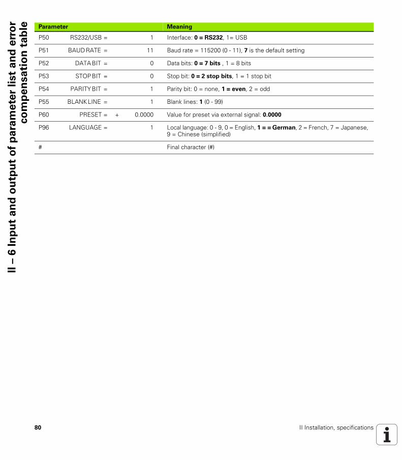
80 II Installation, specifications
II –
6 I
np
ut
an
d o
utp
ut
of
pa
ram
ete
r li
st
an
d e
rro
rco
mp
en
sa
tio
n t
ab
le
P50 RS232/USB = 1 Interface: 0 = RS232, 1= USB
P51 BAUD RATE = 11 Baud rate = 115200 (0 - 11), 7 is the default setting
P52 DATA BIT = 0 Data bits: 0 = 7 bits , 1 = 8 bits
P53 STOP BIT = 0 Stop bit: 0 = 2 stop bits, 1 = 1 stop bit
P54 PARITY BIT = 1 Parity bit: 0 = none, 1 = even, 2 = odd
P55 BLANK LINE = 1 Blank lines: 1 (0 - 99)
P60 PRESET = + 0.0000 Value for preset via external signal: 0.0000
P96 LANGUAGE = 1 Local language: 0 - 9, 0 = English, 1 = = German, 2 = French, 7 = Japanese, 9 = Chinese (simplified)
# Final character (#)
Parameter Meaning

ND 280 81
II –
6 I
np
ut
an
d o
utp
ut
of
pa
ram
ete
r li
st
an
d e
rro
rco
mp
en
sa
tio
n t
ab
leOutput format of the error compensation table
First line
Each error compensation table output begins with the start character < # > (HEX: 0x23).
Second line
Model of position display unit and unit of measure
Third line
Output of axis to be compensated:
Fourth line
Output of compensation point spacing (only for linear encoders):
The ND outputs a separate error compensation table for each axis to be compensated.
# <CR> <LF>
1
1 Start character and end of line: 3 characters
N D - 2 8 0 M M <CR> <LF>
2 3 4
2 Model of display unit, left-aligned: 13 characters3 Unit of measure: 6 characters4 End of line: 2 characters
A X I S X 1 = 0 <CR> <LF>
5 6 7 8
5 Axis to be compensated, left-aligned: 13 characters6 Separator block: 3 characters7 Axis value, right-aligned: 6 characters8 End of line: 2 characters
S P A C I N G = + 1 0 . 0 0 0 0 <CR> <LF>
9 10 11 12
9 Spacing: 13 characters10 Separator block: 3 characters11 Value for spacing, right-aligned: 13 characters12 End of line: 2 characters
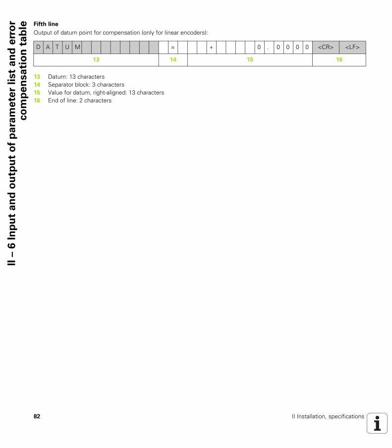
82 II Installation, specifications
II –
6 I
np
ut
an
d o
utp
ut
of
pa
ram
ete
r li
st
an
d e
rro
rco
mp
en
sa
tio
n t
ab
le Fifth line
Output of datum point for compensation (only for linear encoders):
D A T U M = + 0 . 0 0 0 0 <CR> <LF>
13 14 15 16
13 Datum: 13 characters14 Separator block: 3 characters15 Value for datum, right-aligned: 13 characters16 End of line: 2 characters

ND 280 83
II –
6 I
np
ut
an
d o
utp
ut
of
pa
ram
ete
r li
st
an
d e
rro
rco
mp
en
sa
tio
n t
ab
leSixth line
Output of compensation value no. 0:
Subsequent lines for further compensation values
Output of compensation values 1 - 199 for linear measurements (1 - 179 for angular measurements):
Last line
Each error compensation table output ends with the final character < # > (HEX: 0x23).
C O M P . N 0 . 0 0 0 = + 0 . 0 0 0 0 =
17 18 19 20
+ 0 . 0 0 0 0 <CR> <LF>
21 22
17 Compensation number zero, left-aligned: 13 characters18 Separator block: 3 characters19 Compensation position zero, right-aligned: 13 characters20 Separator block: 3 characters21 Compensation value zero, right-aligned: 13 characters22 End of line: 2 characters
C O M P . N 0 . 1 9 9 = + 1 9 9 0 . 0 0 0 0 =
23 24 25 26
+ 0 . 1 2 3 5 <CR> <LF>
27 28
23 Compensation number 199, left-aligned: 13 characters24 Separator block: 3 characters25 Compensation position 199, right-aligned: 13 characters26 Separator block: 3 characters27 Compensation value 199, right-aligned: 13 characters28 End of line: 2 characters
# <CR> <LF>
29
29 Final character and end of line: 3 characters
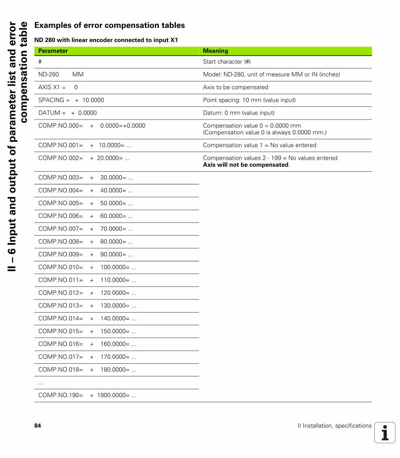
84 II Installation, specifications
II –
6 I
np
ut
an
d o
utp
ut
of
pa
ram
ete
r li
st
an
d e
rro
rco
mp
en
sa
tio
n t
ab
le Examples of error compensation tables
ND 280 with linear encoder connected to input X1
Parameter Meaning
# Start character (#)
ND-280 MM Model: ND-280, unit of measure MM or IN (inches)
AXIS X1 = 0 Axis to be compensated
SPACING = + 10.0000 Point spacing: 10 mm (value input)
DATUM = + 0.0000 Datum: 0 mm (value input)
COMP.NO.000= + 0.0000=+0.0000 Compensation value 0 = 0.0000 mm (Compensation value 0 is always 0.0000 mm.)
COMP.NO.001= + 10.0000= ... Compensation value 1 = No value entered
COMP.NO.002= + 20.0000= ... Compensation values 2 - 199 = No values enteredAxis will not be compensated.
COMP.NO.003= + 30.0000= ...
COMP.NO.004= + 40.0000= ...
COMP.NO.005= + 50.0000= ...
COMP.NO.006= + 60.0000= ...
COMP.NO.007= + 70.0000= ...
COMP.NO.008= + 80.0000= ...
COMP.NO.009= + 90.0000= ...
COMP.NO.010= + 100.0000= ...
COMP.NO.011= + 110.0000= ...
COMP.NO.012= + 120.0000= ...
COMP.NO.013= + 130.0000= ...
COMP.NO.014= + 140.0000= ...
COMP.NO.015= + 150.0000= ...
COMP.NO.016= + 160.0000= ...
COMP.NO.017= + 170.0000= ...
COMP.NO.018= + 180.0000= ...
...
COMP.NO.190= + 1900.0000= ...

ND 280 85
II –
6 I
np
ut
an
d o
utp
ut
of
pa
ram
ete
r li
st
an
d e
rro
rco
mp
en
sa
tio
n t
ab
le
COMP.NO.191= + 1910.0000= ...
COMP.NO.192= + 1920.0000= ...
COMP.NO.193= + 1930.0000= ...
COMP.NO.194= + 1940.0000= ...
COMP.NO.195= + 1950.0000= ...
COMP.NO.196= + 1960.0000= ...
COMP.NO.197= + 1970.0000= ...
COMP.NO.198= + 1980.0000= ...
COMP.NO.199= +1990.0000= ...
# Final character (#)
Parameter Meaning
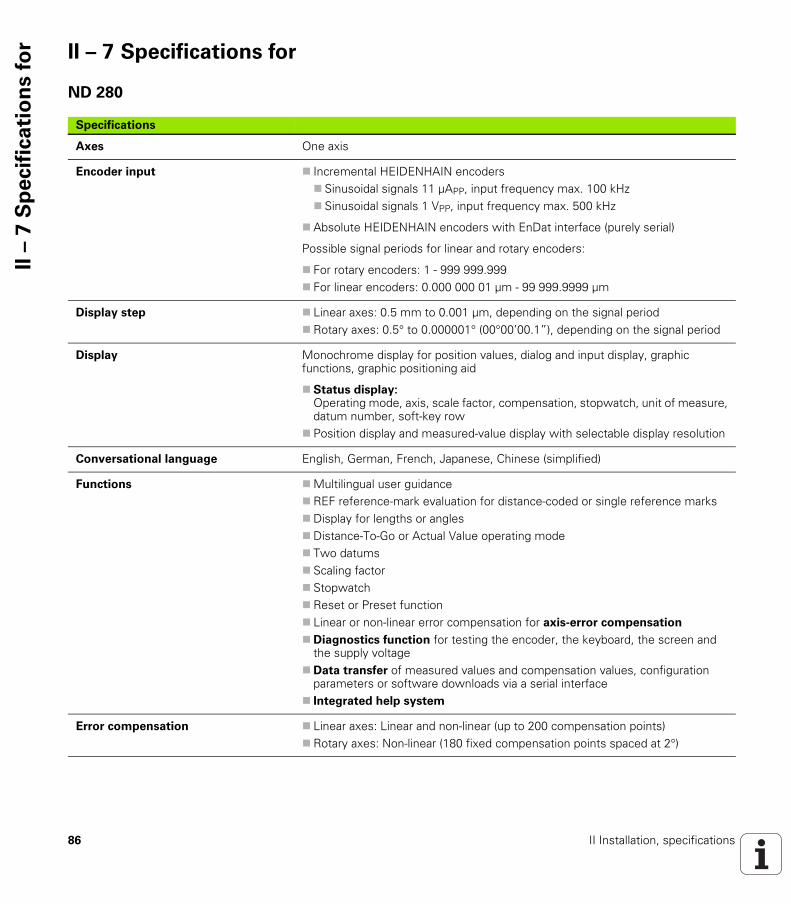
86 II Installation, specifications
II –
7 S
pe
cif
ica
tio
ns f
or II – 7 Specifications for
ND 280
Specifications
Axes One axis
Encoder input Incremental HEIDENHAIN encoders Sinusoidal signals 11 µAPP, input frequency max. 100 kHz Sinusoidal signals 1 VPP, input frequency max. 500 kHz
Absolute HEIDENHAIN encoders with EnDat interface (purely serial)
Possible signal periods for linear and rotary encoders:
For rotary encoders: 1 - 999 999.999 For linear encoders: 0.000 000 01 µm - 99 999.9999 µm
Display step Linear axes: 0.5 mm to 0.001 µm, depending on the signal periodRotary axes: 0.5° to 0.000001° (00°00’00.1”), depending on the signal period
Display Monochrome display for position values, dialog and input display, graphic functions, graphic positioning aid
Status display: Operating mode, axis, scale factor, compensation, stopwatch, unit of measure,datum number, soft-key row
Position display and measured-value display with selectable display resolution
Conversational language English, German, French, Japanese, Chinese (simplified)
Functions Multilingual user guidanceREF reference-mark evaluation for distance-coded or single reference marksDisplay for lengths or anglesDistance-To-Go or Actual Value operating mode Two datums Scaling factor StopwatchReset or Preset function Linear or non-linear error compensation for axis-error compensation
Diagnostics function for testing the encoder, the keyboard, the screen and the supply voltage
Data transfer of measured values and compensation values, configuration parameters or software downloads via a serial interface
Integrated help system
Error compensation Linear axes: Linear and non-linear (up to 200 compensation points)Rotary axes: Non-linear (180 fixed compensation points spaced at 2°)
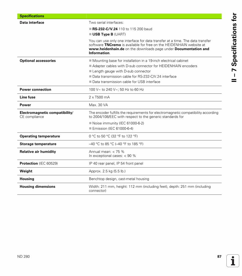
ND 280 87
II –
7 S
pe
cif
ica
tio
ns f
or
Data interface Two serial interfaces:
RS-232-C/V.24 110 to 115 200 baudUSB Type B (UART)
You can use only one interface for data transfer at a time. The data transfer software TNCremo is available for free on the HEIDENHAIN website at www.heidenhain.de on the downloads page under Documentation and Information.
Optional accessories Mounting base for installation in a 19-inch electrical cabinetAdapter cables with D-sub connector for HEIDENHAIN encoders Length gauge with D-sub connectorData transmission cable for RS-232-C/V.24 interfaceData transmission cable for USB interface
Power connection 100 V~ to 240 V~; 50 Hz to 60 Hz
Line fuse 2 x T500 mA
Power Max. 30 VA
Electromagnetic compatibility/CE compliance
The encoder fulfills the requirements for electromagnetic compatibility according to 2004/108/EEC with respect to the generic standards for
Noise immunity (IEC 61000-6-2) Emission (IEC 61000-6-4)
Operating temperature 0 °C to 50 °C (32 °F to 122 °F)
Storage temperature –40 °C to 85 °C (–40 °F to 185 °F)
Relative air humidity Annual mean: < 75 %In exceptional cases: < 90 %
Protection (IEC 60529) IP 40 rear panel, IP 54 front panel
Weight Approx. 2.5 kg (5.5 lb.)
Housing Benchtop design, cast-metal housing
Housing dimensions Width: 211 mm, height: 112 mm (including feet), depth: 251 mm (including connector)
Specifications

88 II Installation, specifications
II –
8 D
ime
nsio
ns II – 8 Dimensions
ND 280
Front view with dimensions
Dimensions in mm
Side view with dimensions
Bottom view with dimensions
HEIDENHAIN
Dimensions in mm
Tolerancing ISO 8015ISO 2768 - m H< 6 mm: ±0.2 mm

ND 280 89
II –
9 A
cce
sso
rie
sII – 9 Accessories
ID numbers for accessories
ID number Accessories
654020-01 Mounting base for installation in a 19-inch electrical cabinet, packaged
366964-xx Data transfer cable for RS-232-C/V.24 interface, packaged
354770-xx Data transfer cable for USB interface, packaged
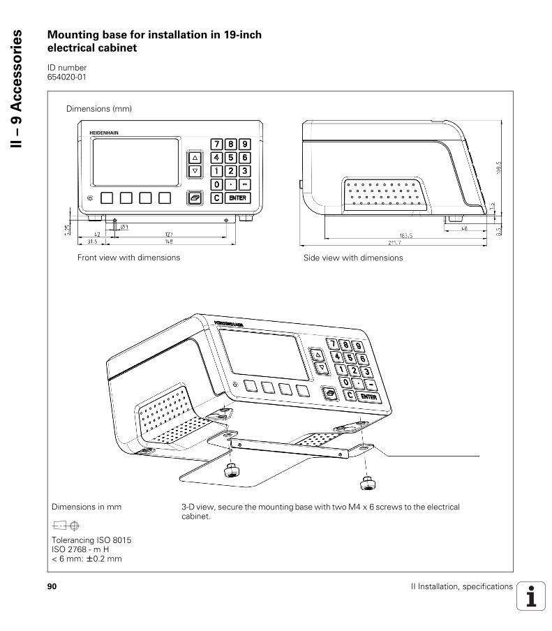
90 II Installation, specifications
II –
9 A
cce
sso
rie
s Mounting base for installation in 19-inch
electrical cabinet
ID number 654020-01
Dimensions (mm)
HEIDENHAIN
Front view with dimensions Side view with dimensions
3-D view, secure the mounting base with two M4 x 6 screws to the electrical cabinet.
Dimensions in mm
Tolerancing ISO 8015ISO 2768 - m H< 6 mm: ±0.2 mm
ND 280 91
Ind
exA
Absolute coordinates ... 15Absolute datum ... 13Absolute position encoders ... 16Absolute workpiece positions ... 15Accessories ... 34, 89Actual position ... 14Actual Value/Distance-To-Go soft
key ... 25
BBasic functions ... 18
CC key ... 22CE compliance ... 36Connecting cable, wiring ... 65Console adjustment ... 31Counter settings ... 46
DData input ... 22Data input forms ... 24Data interface ... 61Data transfer
Control characters ... 63Data format ... 63from PC ... 63Signal level ... 65to a printer ... 62to PC ... 62
Datum setting ... 26, 30Datums ... 13Diagnostics ... 55
Display test ... 55Encoder test ... 56Keypad test ... 55Power supply ... 58
Dimensions ... 88Display configuration ... 45Display value, setting ... 26Distance-coded reference marks ... 17Distance-to-go ... 14
EElectrical connection ... 37Electrical requirements ... 37Electromagnetic compatibility
(EMC) ... 36Encoder parameters ... 59Encoder setup ... 41
Absolute encoder ... 44Incremental linear encoder ... 42Incremental rotary encoder ... 43Multiturn rotary encoder ... 44
Encoders, connecting the ... ... 38ENTER key ... 22Environmental conditions ... 35Error compensation ... 47
Error compensation table, creating... ... 50
Linear ... 48Non-linear ... 49
Error compensation table ... 50Configuring ... 51Examples ... 84Export ... 52Graph, viewing... ... 51Import ... 52Output format ... 81Viewing ... 51
Error messages ... 24, 32External operation ... 67
FFactory defaults ... 46Firmware update ... 64Fixed reference marks ... 17Fundamentals of positioning ... 13
GGrounding ... 37
HHelp system ... 23
IIncremental coordinates ... 15Incremental position encoders ... 16Incremental workpiece positions ... 15Installation setup ... 40INSTALLATION SETUP menu ... 40Instruction box ... 24Instruction messages ... 24Integrated help system ... 23Interface, setting up... ... 53Items supplied ... 34
JJob Setup ... 25Job Setup menu ... 27, 40
KKeypad, using the... ... 22
LLanguage (setting) ... 31Linear encoders from
HEIDENHAIN ... 59
MMaintenance ... 38Measured value output ... 74
Via data interface ... 74Mirror ... 29Mounting ... 35Mounting and installation ... 35Mounting base ... 90Mounting location ... 35
NND, power-up ... 18ND, shutdown ... 19NO REF soft key ... 19Nominal position ... 14Non-linear error compensation ... 49
OOperating modes ... 25Optional accessories ... 34
PParameter list
Example ... 79Input and output ... 77Output format ... 78
Passcode ... 40Position encoders ... 16Position feedback ... 16Possible applications ... 12Power connector ... 37Power-up ... 18Preventative maintenance ... 38
92
Ind
ex R
REF ... 16Reference mark evaluation ... 19Reference marks ... 17
Crossing over ... 19Not crossing over ... 19
Repair ... 38Rotary encoders from
HEIDENHAIN ... 60RS-232-C/V.24 interface ... 53, 61
SScaling factor ... 29Screen layout ... 20Serial data transfer ... 62Serial port ... 53Soft key LIST OF TOPICS ... 23Soft key mm/inch ... 28Soft-key functions ... 21Software update (firmware
update) ... 64Specifications ... 86Stacking ... 35Standard screen ... 20Stopwatch (setting) ... 30
UUnit of measure, setting ... 28Up/Down arrow keys ... 22Update ... 64USB interface ... 53, 61, 66
VValue for datum point ... 30
WWiring the connecting cable ... 65
RS-232-C/V.24 ... 65USB ... 66
662205-22 · Ver02 · pdf · 11/2013