ger rapix techbroch fa single.indd 1 1/04/2016 4:26 pm · simpler to design easier to install ......
TRANSCRIPT

GER_Rapix_TechBroch_FA_Single.indd 1 1/04/2016 4:26 pm

Why lighting control matters 3
Lighting control strategies 5
GETTING TO KNOW RAPIX
The RAPIX Lighting Control System 9
Xi Extended Intelligence 10
The Gerard Total Lighting Solution 12
RAPIX Lighting Control System Architecture 13
System ComponentsZone Controller 15 eHub Application Controller 18 Wall Switches 19 Visualisation Software 21
TECHNICAL INFORMATION
RAPIX LCS Details and Design Parameters 25
Product Technical Information 27
GER_Rapix_TechBroch_FA_Single.indd 2 1/04/2016 4:26 pm

REDUCE DESIGN AND INSTALL TIMES WITH THE FUTURE OF COMMERCIAL LIGHTING CONTROL
Introducing the RAPIX Lighting Control System, a new DALI and Ethernet based system that is purpose-built for commercial buildings – unlike ‘one-size-fits-all’ competitive offerings. The RAPIX Lighting Control System strips away layers of complexity to greatly accelerate the design, installation and commissioning of lighting control. Welcome to a new era of brilliant simplicity – with simply brilliant commercial implications.
This brochure is designed to provide you with the technical information you need to design and specify the RAPIX Lighting Control System.
Simpler to design
Easier to install
Faster to commission
GER_Rapix_TechBroch_FA_Single.indd 3 1/04/2016 4:26 pm

Why lighting control matters
Lighting control is an increasingly important part of overall lighting design in commercial buildings, and today’s lighting control technologies offer more scope than ever to manage costs and deliver business benefits.
Well-designed lighting control can help building owners reduce lighting energy costs, command higher rents, facilitate longer leases, and provide safer, healthier and more productive working environments.
With the advent of the new DALI-based RAPIX Lighting Control System, designing and installing lighting controls that help to deliver these benefits is simpler and easier than ever before.
Energy savings
Lighting can be responsible for up to 40% of an office building’s total power usage. Well designed lighting control can save up to 60%* of lighting energy, without compromising light quality, user comfort or safety.
Reducing utility costs
To encourage organisations to reduce energy usage during peak hours, utility companies increasingly employ ‘time of day’ and ‘maximum demand’ energy tariffs. Effective lighting controls make it simple and easy to dim or switch off lights and cut energy usage at these peak times.
Employee safety, productivity and wellbeing
When it comes to creating safe and productive workplaces, lighting control plays a major role. For example, when an area of a building is occupied, corridor lighting should be left on so that exit routes from the area are lit. A dimmed lighting level surrounding the occupied area also helps to provide those working there with a reassuring sense of safety.
An effective lighting control system can leverage the capabilities of LED-based DALI luminaires to change colour temperature or light level. In this way, lighting can help to reinforce natural circadian rhythms, enhancing employee wellbeing, alertness and productivity.
Pollution reduction
Increasingly, organisations demand buildings with better environmental performance. Buildings that deliver this can attract higher rents and be easier to tenant. Well-designed lighting controls can greatly assist in reducing energy usage and contribute to Green Star© and NABERS© points, which helps to showcase a building’s environmental credentials.
3 * Source: Green Building Council Australia.
GER_Rapix_TechBroch_FA_Single.indd 4 1/04/2016 4:26 pm

Efficient facility management
The best lighting control systems give building managers effective software tools that help them maximise building efficiency. These include software that can log the time all luminaires are run, along with any faults. The latest DALI-compliant LED luminaires are capable of alerting the lighting control system when faults occur. Fault alerts can be sent by email or text message to the facility manager. Together, all this information can be used to improve planned maintenance schedules, and facilitate more efficient management of the whole lighting installation.
Building Code compliance
Effective lighting control systems can also greatly assist with Building Code compliance. Thanks to the energy savings that flow from an effective lighting control system, it may be possible to exceed the illumination power densities specified in the Building Code.
4
GER_Rapix_TechBroch_FA_Single.indd 5 1/04/2016 4:26 pm

Lighting control strategies
With the brilliant simplicity of the DALI-based RAPIX Lighting Control System, it’s much simpler and easier to exploit the following lighting control strategies without the need for complex system integration.
Daylight harvesting
Light level sensors help to cut energy use by reducing artificial light when adequate natural light is available. ‘Daylight harvesting’ works by reducing artificial light levels slowly as natural light levels increase. The trick is to make sure that adjustment of light levels is unobtrusive and undisruptive to workers.
Time-based control
One of the most effective ways to cut lighting energy usage is time-based control. Time-based control may be set to clock times, in response to sunrise or sunset, or based on the time of day a particular task is performed; for example, a factory may need bright lighting while machinery is being operated, but much lower levels while the area is simply being cleaned, or inspected by security staff.
Time-based controls can be used to set many other parameters; for example, lights that require switching on and off manually during daylight hours could be programmed to come on automatically after dark if movement is detected.
Occupancy-based control
To save lighting energy, occupancy sensors (or movement sensors) can be used to automatically dim or switch off lights in unoccupied areas. Movement sensors can also be used to switch on lights automatically when somebody enters an area; this is especially useful in areas that lack any natural lighting.
One successful energy reduction strategy using occupancy sensors is called ‘request ON, auto OFF’. Employees switch on lighting in a particular area when they need it. When the area is no longer occupied, the lighting is automatically turned off. As they leave the area, employees can also usually switch off the lighting manually.
Maintained illuminance
Over time most luminaires will lose some of their brightness. And when it comes to designing a grid of luminaires, the most visually pleasing format may not produce the desired (or ‘maintained’) light level when every luminaire is on full. When the control system uses selective dimming to reduce illuminance to the maintained level, 10-20% of lighting energy can be saved.
5
GER_Rapix_TechBroch_FA_Single.indd 6 1/04/2016 4:26 pm

Scene setting
Within certain areas of a building, manual controls may be used to choose from a menu of pre-arranged lighting effects. Scene setting is often used in boardrooms, meeting spaces and other areas where presentations and other business or social gatherings take place. Pre-arranged lighting effects in each ‘scene’ can be configured to facilitate a range of activities.
Personal tuning
Giving employees the ability to personally ‘tune’ their lighting based on their task, mood, personal preferences or other conditions is can make them more productive. Employees in buildings with lighting control systems that offer numerous and convenient user overrides are happier and more content.
Cumulative strategies made easier with RAPIX LCS
For best results, several of the above strategies may be used together, with each making an additional contribution to the overall energy savings delivered.
Strategies employed together may include:
• Local controls enable personal tuning.• Occupancy sensors switch off lights in unoccupied areas.• Daylight harvesting detects adequate natural light and dims artificial lighting.• Time based controls reduce energy use and light levels outside working hours.• Dimming control maintains illuminance and prevent over-lighting.• Manual ON control ensures occupants really need artificial light.
With the ability to monitor, configure and control any combination of luminaires and input devices, regardless of their position in the network or the DALI Line to which they’re physically connected, the DALI-based RAPIX Lighting Control System makes these strategies more achievable than ever before.
6
GER_Rapix_TechBroch_FA_Single.indd 7 1/04/2016 4:26 pm

GER_Rapix_TechBroch_FA_Single.indd 8 1/04/2016 4:26 pm

GETTING TO KNOW THE RAPIX
LIGHTING CONTROL SYSTEM
GER_Rapix_TechBroch_FA_Single.indd 9 1/04/2016 4:26 pm

9
Light fitting communicationBuilding wide communication
ETHERNET
ETHERNET
LEGACY LIGHTING CONTROL SYSTEM
DALI Gateways (hardware and
software)
Ethernet Gateways (hardware and
software)
The RAPIX LCS is designed to communicate directly with both Ethernet and DALI, removing the need for a middle system layer with additional gateways and/or other devices. As a result, the system architecture is dramatically simplified. With less hardware required, there is less hardware cost, and also less to go wrong during the service life of the building.
The brilliant simplicity of RAPIX LCS also helps eliminate the time and money-wasting patchwork of complex integration and post-installation troubleshooting that’s often needed to make lighting systems perform as expected.
A whole new level of freedom and flexibility
With the RAPIX LCS you can achieve more in less time without compromising lighting control sophistication. Because it is designed to comply with DALI open standards, the RAPIX Lighting Control System can be used with any DALI compliant light fixtures. In other words, you’re not tied to a single luminaire vendor, and can enjoy a whole new level of freedom and flexibility in lighting design.
RAPIX LCS makes lighting control for commercial buildings simpler to design, easier to install and faster to commission. All of which helps achieve more in less time, and greatly reduces cost and risk.
Remove the barriers with RAPIX LCS
Based on Ethernet and DALI, the RAPIX Lighting Control System (‘LCS’) was built from the ground up to meet the requirement for lighting control systems that are ready for the ‘Internet of Things’ – and deliver that new capability with brilliant simplicity.
Current and legacy lighting control systems require additional hardware and software (usually called gateways) to leverage DALI and Ethernet, adding cost and complexity at every stage of the process.
GER_Rapix_TechBroch_FA_Single.indd 10 1/04/2016 4:26 pm

10
Ultimate flexibility and control with Xi Extended Intelligence
While all DALI devices share a common set of commands, the DALI protocol does impose certain limitations, which can be restrictive in certain lighting applications.
With Xi Extended Intelligence, Diginet has created the next generation of digital intelligence for DALI, with an extensive set of extended commands for DALI lighting networks. With Xi Extended Intelligence at its heart, RAPIX LCS allows a host of lighting control capabilities above and beyond the DALI standard, while remaining DALI compliant.
Xi Extended Intelligence from Diginet makes the RAPIX LCS the world’s most innovative DALI compliant control system.
For example, Xi enables all DALI luminaires on all DALI Lines to be connected and controlled as one complete virtual network. This allows lighting control ‘Zones’ to be quickly and easily created in software, regardless of physical connections to DALI Lines. In other words, any luminaire or device, on any DALI Line, can be joined into a ‘Zone’ with any other – and it all happens ‘virtually’, with no need for any changes to physical wiring.
The number of ‘Zones’ that can be created – and the ways they can be configured, controlled and fine-tuned – is virtually unlimited.
GER_Rapix_TechBroch_FA_Single.indd 11 1/04/2016 4:26 pm

11
4 more reasons to choose RAPIX LCSScalable architecture
In addition to being simpler, RAPIX LCS architecture is also highly scalable. From boardrooms to single-level tenancies to large buildings, RAPIX LCS can be easily scaled to suit all lighting control applications.
Security
Many lighting control systems are an open invitation to online intruders. With standard encryption, script replay guards and authenticated communications, the RAPIX Lighting Control System has the security of your client’s control systems and data as a core requirement. In 2016 and beyond, only systems that provide this level of security are acceptable.
RAPIX LCS comes secure and ready to be installed on the integrated communications networks found in modern buildings, reducing duplicate cabling and labour costs associated with running separate lighting control networks.
Reliable communications
Many control systems use UDP communication protocol as a means for transporting information over Ethernet. The drawback with this is that the UDP protocol just sends information – there is no acknowledgement and therefore no guarantee of delivery. RAPIX LCS does not use UDP. It is unique in that it uses a reliable multicast based Ethernet communication protocol to provide a guaranteed service.
Third-party integration
Our Engineers have developed a simple-to-implement protocol based on TCP/IP that allows seamless integration of third party systems with RAPIX LCS. Embedded or PC based integration can be quickly and easily achieved.
GER_Rapix_TechBroch_FA_Single.indd 12 1/04/2016 4:26 pm
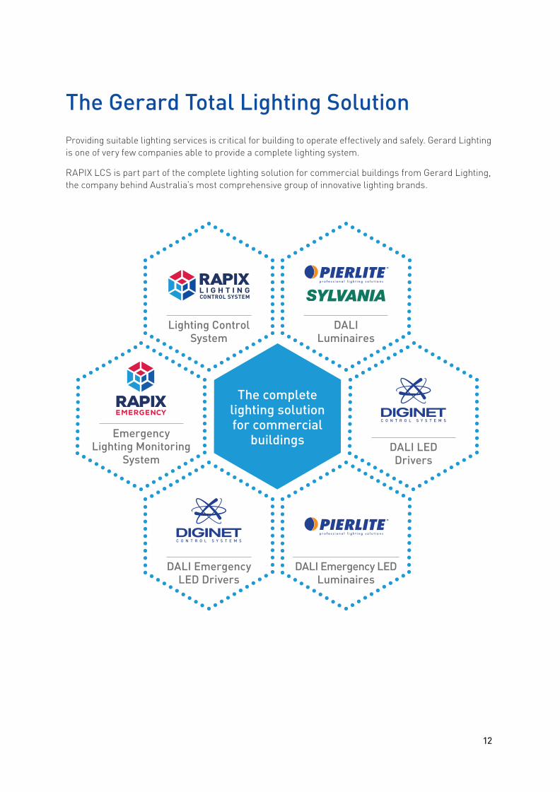
The Gerard Total Lighting SolutionProviding suitable lighting services is critical for building to operate effectively and safely. Gerard Lighting is one of very few companies able to provide a complete lighting system.
RAPIX LCS is part part of the complete lighting solution for commercial buildings from Gerard Lighting, the company behind Australia’s most comprehensive group of innovative lighting brands.
12
Lighting Control System
Emergency Lighting Monitoring
System
DALI Emergency LED Drivers
DALI Luminaires
DALI LED Drivers
DALI Emergency LED Luminaires
The complete lighting solution for commercial
buildings
GER_Rapix_TechBroch_FA_Single.indd 13 1/04/2016 4:26 pm

13
System Architecture
The architecture of the RAPIX Lighting Control System consists of two levels. At the heart of each is one major RAPIX LCS product.
Ethernet Level Architecture
At the Ethernet level, the RAPIX Zone Controller seamlessly and securely integrates DALI and Ethernet.
• A RAPIX Zone Controller is used to connect up to four DALI Lines to the system.
• Zone Controllers are then connected together using a standard Ethernet network.
• To form the system backbone, each Zone Controller can be connected to a standard Ethernet switch, or daisy-chained together via built-in Ethernet ports. All DALI Lines are now stitched together via Ethernet, forming one system-wide lighting control network.
• RAPIX Integrator software connected via a PC can now be used to create the required control Zones.
DALI Line 1
DALI Line 4
DALI Line 2DALI Line 3
DALI Line 1
DALI Line 4
DALI Line 2DALI Line 3
Ethernet Network
Ethernet Network daisy-chained
DALI Line 1
DALI Line 4
DALI Line 2DALI Line 3
DALI Line 1
DALI Line 4
DALI Line 2DALI Line 3
Ethernet NetworkEthernet Network daisy-chained
Floor A
Floor B
EthernetNetwork
Ethernet Switch
Ethernet Switch
PC running Visualisation Software
Ethernet Network daisy-chainedto further Zone controllers on the floor
Ethernet Network to furtherfloors/Zone Controllers
The number of DALI Lines and Zone Controllers connected can be expanded according to the application and is practically limitless.
GER_Rapix_TechBroch_FA_Single.indd 14 1/04/2016 4:26 pm

14
DALI Level Architecture
At the DALI level, the RAPIX eHub Application Controller connects input peripherals and the DALI Line.
• Like any DALI compliant system, each DALI Line requires a DALI power supply unit.
• DALI luminaires, DALI emergency luminaires and exit signs are connected to each DALI Line.
• Other DALI compliant devices, such as Diginet relay devices, are also connected to the line.
• Up to 64 DALI compliant devices can be connected to a single DALI Line.
• eHub DALI application controllers are used to connect input devices such as switches and sensors to a DALI line. The eHub manages all power requirements, logical functions and DALI communication for these devices, enabling them to communicate with the DALI Line.
• The eHub includes connections for four smart input devices, and two additional input connections for occupancy sensors and/or dry contacts.
• eHubs do not require a DALI Short Address and draw only 2mA from the DALI Line.
DALI Lines 1, 2 and 3
PIR OccupancySensor
Ethernet daisy-chained tofurther Zone controllers
Zone Controller
DALIPSU
DALI luminaires DALI luminaires
DALI Relay
DALI luminairesDALI EM luminaires
Switch Inputs
Daylight sensor
MicrophonicOccupancy
Sensor
DALI Input Hub
eHubDALI Line 4
PIR OccupancySensor
Switch Inputs
Daylight sensor
MicrophonicOccupancy
Sensor
DALI Input Hub
eHub
Up to 24 eHubs can be connected to a single DALI line, providing huge capacity to connect input devices with unheard-of simplicity.
GER_Rapix_TechBroch_FA_Single.indd 15 1/04/2016 4:26 pm

System Components
All components of the RAPIX Lighting Control System are fully DALI compliant, connecting seamlessly to enable lighting control design of brilliant simplicity.
RAPIX Zone Controller
Seamlessly and securely integrates DALI and Ethernet to enable the creation of powerful RAPIX ‘Zones’.
The RAPIX Zone Controller is an embedded Ethernet/DALI controller for the Diginet RAPIX Lighting Control System that supports seamless joining of individual DALI lines in a building. Each Zone Controller can connect up to four physical DALI Lines, and communicate over an Ethernet network to lines on other Zone Controllers.
The controller software allows DALI Devices and DALI Groups across any DALI Line to be linked together to form DALI Xi ‘Zones’ and ‘Scenes’ to suit the specific lighting needs of the building’s occupants. The rules engine in the controller can run user-configurable scripts to track and control DALI devices based upon events in the system.
15
The powerful menu system provides an array of system control and information options to assist commissioning and ongoing maintenance.
Controller ‘reset’ button
DALI Line indicators
Ethernet port indicators
Connection DALI Line 1
Connection DALI Line 2
LCD menu screen
Connection for external 5-12V dc
power supply
Power indicator
GER_Rapix_TechBroch_FA_Single.indd 16 1/04/2016 4:26 pm

Main features:
• 12M wide DIN rail mounted embedded controller for the RAPIX Lighting Control System.• Physical connection to four on-board DALI Lines.• Two Ethernet ports with in-built switch for daisy chain connections.• LCD screen and control buttons with menu-driven control interface for easy
programming and commissioning.• Powered via external 5-12V dc supply.• Configured using RAPIX Integrator software tool.• Line joining between DALI Lines on a single controller and/or across controllers.• Zone creation: Zones being collections of DALI Lines and/or DALI Groups and/or DALI Short Addresses.• Zone joining: link Zones to form larger zones.• Zone rules: configurable logic based on states of Zones, DALI Groups and DALI Short Addresses.• Scene control across all connected Zone Controllers and DALI Lines.• Integrated scheduling engine.
16
Connection DALI Line 5
LCD menu screen control buttons
Connection DALI Line 3
Connection DALI Line 4
2-port Ethernet switch
Serial port (future use)
GER_Rapix_TechBroch_FA_Single.indd 17 1/04/2016 4:26 pm

RAPIX Zones
Zone Controllers enable the creation of powerful RAPIX Zones. All lighting devices in an installation are ‘stitched together’ via Zone Controllers and a building’s Ethernet network, forming a single, system-wide lighting network regardless of which DALI Lines they are physically connected to.
Luminaires on any part of this network can then be combined to form Zones, regardless of which DALI Line they are physically connected to. Zones can contain any combination of DALI Short Addresses, DALI Groups and other RAPIX Zones.
RAPIX Integrator software is used to quickly and easily create lighting Zones across any part of the building, independent of all DALI Line or Zone Controller connections. For example, it’s straight forward and easy to create a Zone called ‘Building’, which includes every light in a multi-level building except access routes and lift lobbies. Once the Zone is created, a single command can be sent from a wall switch or the visualisation software to switch the ‘Building’ Zone on or off, or dim it to a specific level.
Creating Zones is as easy as drag and drop
With the power of RAPIX Integrator software at their fingertips, the System Integrator can create the required Zones without having to create any links or routing information. All he or she has to do is simply drag and drop the required lighting from any part of the building into a Zone, and it’s done.
17
Create lighting Zones with unmatched ease and simplicity.
Floor 3 Corridor Zone
Floor 3
Floor 2
Floor 1
All Building Zone
All Lift Lobbies Zone
All Floor 2 Zone
Office Floor 3 Zone
Single Device Zone
Create Zones in moments with simple drag and drop actions.
GER_Rapix_TechBroch_FA_Single.indd 18 1/04/2016 4:26 pm

RAPIX eHub Application Controller
Enabling seamless DALI communication with input devices.
The unique RAPIX eHub application controller is used to connect input devices and peripherals to a DALI Line. The eHub manages all power requirements, logical functions and DALI communication for these devices.
The connected input peripherals, such as RAPIX modular switches and PIR sensors, are then able to communicate with a DALI Line.
Up to 24 eHubs can be connected to a single DALI Line, with each eHub drawing only 2mA from the DALI Line, making them ideal for sophisticated control in modern commercial applications.
Main features:
• Four connections for RAPIX smart input peripherals (wall switches, sensors, etc).
• Input sockets for quick and easy connection of input peripherals.
• Two connectors for occupancy sensors and/or dry contacts inputs.
• Programmed via DALI.
• Suitable for mounting in a ceiling void and fits through a 90mm down-light hole.
Technical details:
• LED indicators for power, DALI and Ethernet.
• Support for 32 Zones, being collections of DALI Groups and/or DALI Short Addresses.
• Support for up to 16 DALI scenes and (additionally) 16 RAPIX scenes.
• Configurable input peripherals actions (For example, a RAPIX Modular switch can be configured as a toggle dimmer, memory dimmer, long press fade time, double tap action and many other configurations).
18
Up to 24 eHubs can be connected to a single DALI Line.
Ethernet connector
12Vdc SELV power supply connection
2 x 12V dc sensor inputs
DALI Line connectors
2 x dry contact inputs
4 x smart inputs
DALI and power indicator
Ethernet indicators
GER_Rapix_TechBroch_FA_Single.indd 19 1/04/2016 4:26 pm

RAPIX Modular Switches
Fit standard Australian wall switch grid plates and function as eHub input peripherals.
Available as ‘Masters’ or ‘Slaves’, RAPIX Modular switches can be configured in RAPIX Integrator Software to perform a wide range of functions. Each switch (both Masters and Slaves) includes two software-configurable LED indicator colours, white and amber.
19
All commissioning is
carried out via Diginet RAPIX software suite.
The configuration is downloaded to
the eHub via a DALI Line.
Push Button Master Push Button Slave
Rocker Master Rocker Slave
Rotary Master Rotary Slave
GER_Rapix_TechBroch_FA_Single.indd 20 1/04/2016 4:26 pm

20
Modular Push Button switches configured for a six-gang wall plate. Switches are labelled and comprised of one Master and five Slaves.
Typical connections between a Master and three Slave RAPIX modular switches in a four gang grid plate.
Modular Master Rotary switch in a single gang wall plate.
Connections from the eHub to master RAPIX modular switch
Master switch to RJ-45 patch lead
Slave switch connectors
Master switch patch lead connector
RJ-45 to eHub patch lead
Cat5/5e cable (up to 100m)
eHub
GER_Rapix_TechBroch_FA_Single.indd 21 1/04/2016 4:26 pm

RAPIX Visualisation Software
Provides the ability to control, monitor and schedule events on DALI networks via a PC app, web browser or smart phone app.
RAPIX Visualisation Software provides simple drag and drop tools that allow the look, feel and layout of the user interface to be customised quickly and easily for specific client applications. Building plans and customised graphics can easily be imported.
The system can also be customised with desktop widgets to allow employees to control their own individual lighting, and maximise their comfort and productivity.
The software provides a Schedule Editor for creating real time based event scheduling. Status information can be represented by text or icons that change condition depending on their state (for example, on, off, dimmed to 50%, etc). This makes building-wide lighting status incredibly easy to monitor.
Main features:
• Create customised user interfaces using drag and drop tools.
• Import building floor plans and customised graphics into the user interface.
• Customise look, feel and layout of user interface to specific client applications.
• Create custom logic scripts with graphical style logic editor.
• Real time event-based scheduling.
• Creating real time based event scheduling with Schedule Editor.
21
PC APP WEB BROWSER SMART PHONE APP
GER_Rapix_TechBroch_FA_Single.indd 22 1/04/2016 4:26 pm

22
Customised interfaces give facility managers
greater control.
Desktop widgets allow employees to control their own lighting.
GER_Rapix_TechBroch_FA_Single.indd 23 1/04/2016 4:26 pm

GER_Rapix_TechBroch_FA_Single.indd 24 1/04/2016 4:26 pm

TECHNICAL INFORMATION
GER_Rapix_TechBroch_FA_Single.indd 25 1/04/2016 4:26 pm

25
RAPIX system details and design parameters
The following lists provide a quick overview of the main parameters that need to be taken into consideration when designing a RAPIX Lighting Control System.
DALI parameters
• The nominal DALI Line voltage range is 9.5Vdc – 22.5Vdc, however it has only Basic Insulation (1500Vac) from mains potential. Therefore, the DALI Line must always be run using double insulated mains wiring.
• Up to 300m of 1.5mm² double insulated mains twin cable on each DALI communication bus (the DALI Line).
• Each DALI Line must include a DALI power supply, with the power supply delivering a maximum of 250mA to the connected DALI Line.
• The Diginet 240mA DALI power supply is 2 DIN Modules wide.
• Up to 64 DALI Devices on each DALI Line (Please note that Diginet recommend a maximum of 55 devices per Line to allow for future additions).
• A DALI Device is typically control gear – a Ballast, Driver or Relay. Please note that a single light fitting may contain more than one piece of control gear.
• Each piece DALI control gear will draw 2mA from the DALI Line.
• DALI Lines do not require communication or network burdens.
GER_Rapix_TechBroch_FA_Single.indd 26 1/04/2016 4:26 pm

26
RAPIX Zone Controller parameters
• Zone Controllers connect to the building LAN to allow high speed communication between all DALI Lines.
• Up to 4 DALI Lines per Zone Controller.
• Each Zone Controller draws 2mA from each connected DALI Line.
• A maximum number of 500 Zone Controller’s (2000 DALI Lines) per installation.
• Each Zone Controller is 12 DIN Modules wide.
• Zone Controllers are powered from external SELV power supplies which are 1 DIN Module wide.
• Each Zone Controller will require a Static IP address.
• Up to 10 Zone Controllers can be daisy chained together (back to a standard Ethernet network switch).
• The maximum distance between the first Zone Controller in a daisy chain and an Ethernet Switch is 100m.
RAPIX eHub and input device parameters
• Up to 24 eHub devices can be connected to each DALI Line.
• Each eHub can support up to 4 switch plates – each with up to 6 switches.
• In addition, each eHub will also support 2 occupancy sensors and 2 dry contact inputs.
• The eHub is typically installed in the roof or ceiling space and is designed to fit through a 90mm hole.
• The eHub is supplied with a plug pack SELV power supply.
• Switch plates can be up to 100m from the eHub via SELV cable (Cat 3 or Cat 5).
• Sensors can be up to 20m from the eHub via SELV cable (Cat 3, Cat 5, etc.).
• eHub devices do not use a DALI Short Address, therefore 64 devices are still available for DALI devices which do use Short Addresses (DALI control gear, for example).
• A DALI eHub device draws 2mA from a DALI Line.
GER_Rapix_TechBroch_FA_Single.indd 27 1/04/2016 4:26 pm

DALI Zone Contoller DGOZ-ZONEC-4DA
An embedded Ethernet/DALI controller for the RAPIX Lighting Control System that supports seamless joining of all individual DALI Lines in a building.
Each Zone Controller can connect up to four physical DALI Lines and communicate over an Ethernet network to lines on other Zone Controllers.
The controller software allows DALI devices and DALI groups across any DALI Line to be linked together to form DALI Xi ‘Zones’ and ‘Scenes’ to suit the application.
The rules engine in the Zone Controller can run user-configurable scripts to track and control DALI devices based upon events in the system.
• 12M wide DIN rail mounted embedded controller for the RAPIX Lighting Control System.
• Physical connection to four on-board DALI Lines.
• Two Ethernet ports with in-built switch for daisy chain connections.
• LCD screen and control buttons with menu driven control interface for easy programming and commissioning.
• Powered via external 5-12Vdc supply.
• Configured using RAPIX Integrator software tool.
• Line joining between DALI Lines, on a single controller and/or across controllers.
• Zone creation – Zones being collections of DALI Lines and/or DALI Groups and/or DALI Short Addresses.
• Zone joining – link Zones to form larger zones.
• Zone rules – configurable logic based on states of Zones, DALI Groups and DALI Short Addresses.
• Scene control across DALI Lines and Zone Controllers.
27
Technical information
GER_Rapix_TechBroch_FA_Single.indd 28 1/04/2016 4:26 pm

28
DALI Single Line Power Supply DGLMPS01
The DALI Single Line Power Supply is part of the Diginet Lighting Management System, which incorporates the Digital Addressable Lighting Interface (DALI) open standard.
Each DALI Line in an installation requires a dedicated DALI power supply for correct operation of the DALI system. The unit provides power for one DALI Line that may contain lighting fixtures, including emergency lighting, RGB colour changing controllers, switches, sensors and interface devices. Each of these DALI devices draws power from the DALI Line, this power being provided by the DALI Power Supply.
• Designed to ensure the maximum current delivered to a DALI Line will not be exceeded.
• Indicators for displaying the mains supply connection and the DALI Line status.
• Nominal rated load current for the DALI Power Supply is 238mA with a guaranteed minimum load current of 225mA.
• DIN rail mounted for quick and easy installation.
DIN Rail Mounted 12V dc Power Supply Unit DGLMPS12DC/1-0A
Powers up to four RAPIX Zone Controllers.
240Vac/12Vdc power supply units recommended for powering one or multiple RAPIX Zone Controllers.
NOTE: these units are not suitable for powering DALI Lines, Use Diginet DALI PSU part number DGLMPS01 for powering a DALI Line.
• DIN rail mounted for quick and easy installation.
• Internal fuse to protect the unit against current over-supply.
• LED power-on indicator on front of unit for quick fault-finding.
• High efficiency switch-mode power supply design.
28
GER_Rapix_TechBroch_FA_Single.indd 29 1/04/2016 4:26 pm

29
DIN Rail Mounted 12V dc Power Supplies DGLMPS12DC/1-5A
Powers up to six RAPIX Zone Controllers.
240Vac/12Vdc power supply units recommended for powering one or multiple RAPIX Zone Controllers.
NOTE: These units are not suitable for powering DALI Lines. Use Diginet DALI PSU part number DGLMPS01 for powering a DALI Line.
• DIN rail mountable for quick and easy installation.
• Internal fuse to protect the unit against current over supply.
• LED power-on indicator on front of unit for quick fault-finding.
• High efficiency switch-mode power supply design.
RAPIX eHub DALI Input Hub DGOZ-IHUB-4G-2S
Connects between RAPIX input peripherals and a DALI Line.
The eHub manages device power requirements, embedded logical functions and DALI communications for the connected peripherals. The connected input peripherals, such as wall switches and sensors, are then able to communicate with a DALI Line.
The unit includes four inputs for connecting to RAPIX Lighting Control System switches or smart sensors, and two additional input connections for occupancy sensors or dry contacts.
The eHub is a compact unit that fits through a standard 90mm down light hole and is suitable for locating in a ceiling void. The eHub is configured via the Diginet RAPIX software suite.
Actions for connected input peripherals are configurable. For example, a RAPIX modular switch can be configured as a toggle dimmer, memory dimmer, long press fade time, double tap action and many other configurations.
• Powered via external 12V dc SELV power supply.
• Input sockets for quick and easy input peripheral connection.
• Segregated terminal block for DALI Line connections.
• LED indicators for power, DALI and Ethernet.
• Suitable for mounting in a ceiling void.
• Fits through a 90mm downlight hole.
• Programmed via DALI.
• Four input connections for RAPIX smart input peripherals.
• Two input connectors for occupancy sensors and/or dry contact input peripherals.
• Support for 32 ‘Zones’, Zones being collections of DALI Groups and/or DALI Short Addresses.
• Support for up to 16 DALI scenes and (additionally) 16 RAPIX scenes.
GER_Rapix_TechBroch_FA_Single.indd 30 1/04/2016 4:26 pm

30
Rotary Switch DGOZ-MOSW-M-RE and DGOZ-MOSW-S-RE
Modular digital Rotary switches with integral push switch for the RAPIX Lighting Control System that fit standard Australian wall plate apertures.
Rotary switches are available as Masters or Slaves. Master Rotary switches connect to a RAPIX eHub. Each Master Rotary switch is capable of being connected to one Slave Rotary switch.
Rotary switches can be configured in RAPIX software to perform a wide range of functions and each module (masters and slaves) includes two software configurable LED indicator colours, white and warm white.
• Two configurable LED colours – white and warm white.
• Fits standard Australian wall plate apertures.
• Master Rotary switches connect to the eHub and are powered via the eHub.
• Slave Rotary switches connect to a Master and are powered via the Master.
• Typical switch functions include: Toggle on/off Fade lights up or down Start or cancel a timer Recall a fixed level Toggle between off and the current level Issue a scene.
• All commissioning is carried out via Diginet RAPIX software suite. The configuration is downloaded to the eHub via a DALI Line.
Push Button Switch DGOZ-MOSW-M-PB and DGOZ-MOSW-S-PB
Modular tactile Push Button switches for the RAPIX Lighting Control System that fit standard Australian wall plate apertures.
Push Button switches are available as Master or Slave mechanisms. Master switches connect to a RAPIX eHub and each Master is capable of being connected to five Slave switches.
Push Button switches can be configured in RAPIX Integrator software to perform a wide range of functions and each module (masters and slaves) includes two software configurable LED indicator colours, white and warm white.
The optional clear button cap on each switch allows the installer to print custom labels via standard inkjet or laser printers (labelling sheets available from Diginet).
• Two configurable LED colours – white and warm white.
• Fits standard Australian wall plate apertures.
• Master Push Button switches connect to the eHub and are powered via the eHub.
• Slave Push Button switches connect to a Master and are powered via the Master.
• Typical switch functions include: Toggle on/off Fade lights up or down Start or cancel a timer Recall a fixed level Toggle between off and the current level Issue a scene.
• All commissioning is carried out via RAPIX Integrator software suite. The configuration is downloaded to the eHub via a DALI Line.
GER_Rapix_TechBroch_FA_Single.indd 31 1/04/2016 4:26 pm

31
Rocker Switch DGOZ-MOSW-M-RO and DGOZ-MOSW-S-RO
Modular momentary Rocker switches for the RAPIX Lighting Control System that fit standard Australian wall plate apertures.
Momentary Rocker switches are available as Masters or Slaves. Master switches connect to a RAPIX eHub and each Master is capable of being connected to five Slave switches.
Rocker switches can be configured in RAPIX Integrator software to perform a wide range of functions and each module (Masters and Slaves) includes two software configurable LED indicator colours, white and warm white.
• Two configurable LED colours – white and warm white.
• Fits standard Australian wall plate apertures.
• Master Rocker switches connect to the eHub and are powered via the eHub.
• Slave Rocker switches connect to a Master and are powered via the Master.
• Typical switch functions include: Toggle on/off Fade lights up or down Start or cancel a timer Recall a fixed level Toggle between off and the current level Issue a scene.
• All commissioning is carried out via Diginet RAPIX Integrator software suite. The configuration is downloaded to the eHub via a DALI Line.
Light Level Sensor DGOZ-LLS-M
The Light Level Sensor can be used as part of a RAPIX Lighting Control System to control a space based on ambient light measurement.
The RAPIX Light Level Sensor connects directly to an eHub and is used to measure light levels in a space and send this information to the eHub for logic processing. The required operation of the light level sensor/eHub is configured in the RAPIX Integrator software package.
Up to three RAPIX PIR occupancy sensors can optionally be directly connected to the light level sensor.
• Connects to and powered from a RAPIX eHub.
• 0 to 4000 Lux sensing range.
• Allows connection to three PIR sensors.
• Fits standard Australian wall plate aperture.
• Suitable for ceiling and wall mount.
• Designed in Australia.
Possible operational setups:
• ‘Daylight harvesting’, where DALI luminaires connected to a RAPIX Lighting Control System are dimmed up or down to maintain a required illuminance (Lux) level on a desktop.
• Set PIR sensor operation based on Light Level, for example: movement detected by PIR turns a RAPIX Zone on, but only in dark; or
movement detected by PIR turns a RAPIX Zone on, but only in light.
• Stepped light level response to allow different events to occur on a RAPIX Lighting Control System at different light levels.
• Sunset/sunrise switch operation. For example lighting switches on at low light/night/dusk and off for sunrise /daylight.
• Enable/disable the light level sensor.
• Enable/disable PIR’s connected to the Light Level Sensor.
GER_Rapix_TechBroch_FA_Single.indd 32 1/04/2016 4:26 pm

32
PIR Occupancy Sensor DGOZ-OS-PIR-360
A compact low profile 360˚ passive infrared (PIR) sensor for connection to a RAPIX eHub.
The sensor includes a detection lens that senses both Minor and Major Movement (as defined by NEMA Standard WD7 – 2011 for Occupancy Motion Sensors).
Movement is detected via a sensor array with 864 fields of view, ensuring reliable operation to a 7m diameter. The device also includes a light sensor for detecting ambient light levels.
Adjustment sliders for time-out and light level are discreetly hidden in the patented sensor head, which pops out to provide easy configuration after installation, without the need for any tools.
• Connect directly to a RAPIX eHub (up to 2 sensors per eHub).
• Unobtrusive 60mm diameter, flush-mount design.
• High sensitivity 360˚ detection array designed for both minor and major movement applications.
• Integrated light level detector to inhibit switch-on if there is sufficient natural light available.
• Adjustment controls easy to read and set without a tool.
• Hidden yet easily accessible sensor head adjustment controls for time-out and light level adjustment.
Dual Technology Occupancy Sensor CM-PDT-9
The Dual Technology Occupancy Sensor with Passive Dual Technology (PDT) first ‘sees’ motion using Passive Infrared (PIR) detection and then engages Microphonics™ to hear sounds that indicate continued occupancy.
This patented technology uses Automatic Gain Control (AGC) to dynamically self-adapt a sensor to its environment by filtering out constant background noise and registering only noises typical of human activity.
This 360° Occupancy Sensor provides line-of-sight PIR detection of small motion in a circular pattern, and combines overlapping Microphonics™ coverage for detection of occupants working in cubical spaces. Bathrooms, large storage areas with shelving, and libraries with study carrels are also easily and cost-effectively controlled by the CM-PDT-9.
• Patented Dual Technology with PIR/ Microphonics detection.
• 360º Coverage Pattern.
• No field calibration or sensitivity adjustments required.
• Connects directly to a RAPIX eHub.
• Powered via a RAPIX eHub.
GER_Rapix_TechBroch_FA_Single.indd 33 1/04/2016 4:27 pm

33
One Channel DALI Relay Device DGOZ-RLY-10A-01
The RAPIX One Channel DALI Relay Device is designed specifically for on/off switching of up to 10 Amps of lighting load via DALI commands issued on a connected DALI Line.
The on-board 240Vac rated relay is capable of switching a full 10A of LED, fluorescent, incandescent and HID lighting loads, suitable for a wide range of commercial and industrial building applications.
• General purpose load switching (ON and OFF) via received DALI commands.
• Capable of switching 10AX @ 240V ac.
• Optional DIN rail mounting bracket.
• Short Address, Group Addresses and DALI scenes can be configured by Diginet RAPIX Addressing software.
Two Channel DALI Relay Device DGOZ-RLY-10A-02
The RAPIX Two Channel DALI Relay Device is designed specifically for on/off switching of up to 10 Amps per channel of lighting load via DALI commands issued on a connected DALI Line.
The two on-board 240V ac rated relays are each capable of switching a full 10A of LED, fluorescent, incandescent and HID lighting loads and is suitable for a wide range of commercial and industrial building applications.
• General purpose load switching (ON and OFF) via received DALI commands.
• Capable of switching 10AX @ 240V ac.
• Optional DIN rail mounting bracket.
• Short Address, Group Addresses and DALI scenes can be configured by Diginet RAPIX Addressing software.
• 100% DALI Compliant for use with DALI systems.
GER_Rapix_TechBroch_FA_Single.indd 34 1/04/2016 4:27 pm
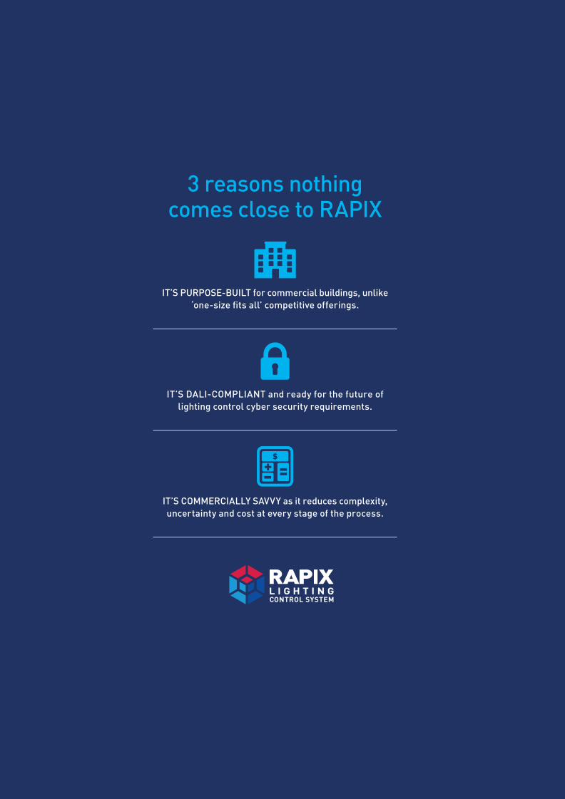
3 reasons nothing comes close to RAPIX
IT’S PURPOSE-BUILT for commercial buildings, unlike ‘one-size fits all’ competitive offerings.
IT’S DALI-COMPLIANT and ready for the future of lighting control cyber security requirements.
IT’S COMMERCIALLY SAVVY as it reduces complexity, uncertainty and cost at every stage of the process.
GER_Rapix_TechBroch_FA_Single.indd 35 1/04/2016 4:27 pm

Sales: 1300 799 300 • Technical: 1300 953 254 diginet.net.au/rapix
Diginet is a brand of Gerard Lighting Pty Ltd.
GER_Rapix_TechBroch_FA_Single.indd 36 1/04/2016 4:27 pm