geothermal systems and...
TRANSCRIPT
1
GEOTHERMAL SYSTEMS AND
TECHNOLOGIES
3. GEOTHERMAL RESERVOIR ENGINEERING

3. GEOTHERMAL RESERVOIR ENGINEERING2
3.1. EXPLORATION OF GEOTHERMAL RESOURCES
Exploration is a significant step in the process of utilization of the geothermal resources. It is aiming at:
� locating geothermal reservoirs for possible exploitation and � selecting the best sites for drilling production wells
with the greatest possible confidence.
Geothermal exploration involves the application of
various methods and techniques to:
⇒ locate reservoirs,
⇒ to characterize their conditions, and
⇒ to optimize the locations of wells
3.1. Exploration of geothermal resources 3
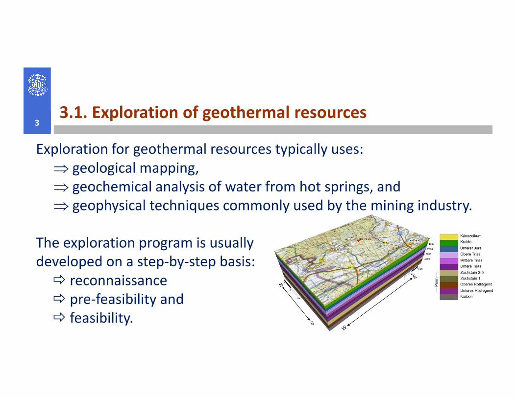
Exploration for geothermal resources typically uses:
⇒ geological mapping,
⇒ geochemical analysis of water from hot springs, and
⇒ geophysical techniques commonly used by the mining industry.⇒ geophysical techniques commonly used by the mining industry.
The exploration program is usually
developed on a step-by-step basis:
� reconnaissance
� pre-feasibility and
� feasibility.
3.1. Exploration of
geothermal resources
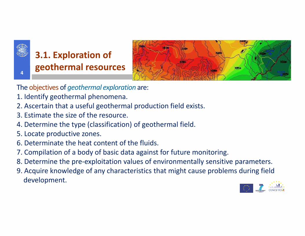
The objectives of geothermal exploration are:
1. Identify geothermal phenomena.
2. Ascertain that a useful geothermal production field exists.
3. Estimate the size of the resource.
4
3. Estimate the size of the resource.
4. Determine the type (classification) of geothermal field.
5. Locate productive zones.
6. Determinate the heat content of the fluids.
7. Compilation of a body of basic data against for future monitoring.
8. Determine the pre-exploitation values of environmentally sensitive parameters.
9. Acquire knowledge of any characteristics that might cause problems during field
development.

3.1. Exploration of geothermal resources 5
3.1.1. Geochemical Methods in Geothermal
Exploration
The major goals of geochemical exploration are:
� to obtain the subsurface composition of the� to obtain the subsurface composition of the
fluids in a geothermal system
� use this to obtain information on temp.,
origin, and flow direction, which help locating
the subsurface reservoir.
Geochemical methods are extensively used and
play a major role in geothermal exploration and
exploitation.

3.1.1. Geochemical Methods in Geothermal Exploration6
Subsurface waters classification:
� Meteoric water
� Ocean water
� Metamorphic water� Metamorphic water
� Magmatic water
Geothermal waters classification based on major ions:
� Alkali-chloride water
� Acid sulfate water
� Acid sulfate-chloride water
� Bicarbonate water
3.1.1. Geochemical Methods in Geothermal Exploration7
In the exploratory phase the task of geochemistry is mainly to:
� Estimate subsurface temperatures,
� Identify the origin of the geothermal fluid,
� Define chemical properties of the fluid with respect to environmental issues,
Provide data for the concept model.� Provide data for the concept model.
In the phase of exploration drilling the main task of geochemistry is to:
� Provide information on water to steam ratio in the reservoir,
� Assess the quality of the geothermal fluid with respect to the intended use,
� Assess the quality of the geothermal fluid with respect to the environment,
� Provide information on scaling tendencies of the fluid,
� Provide additional information to the concept model of the geothermal reservoir.
3.1.1. Geochemical Methods in Geothermal Exploration8
In the phase of production drilling and operation of a power plant:
� Identify recharge into the reservoir of shallow groundwater or deeper hot water
� Assess boiling processes in production aquifers
� Identify changes in the chemistry of the geothermal fluid
� Quantify changes in scaling and corrosion tendencies
� Monitor the quality of the geothermal fluid with respect to the environment
3.1.2. Geophysical Methods in Geothermal Exploration9
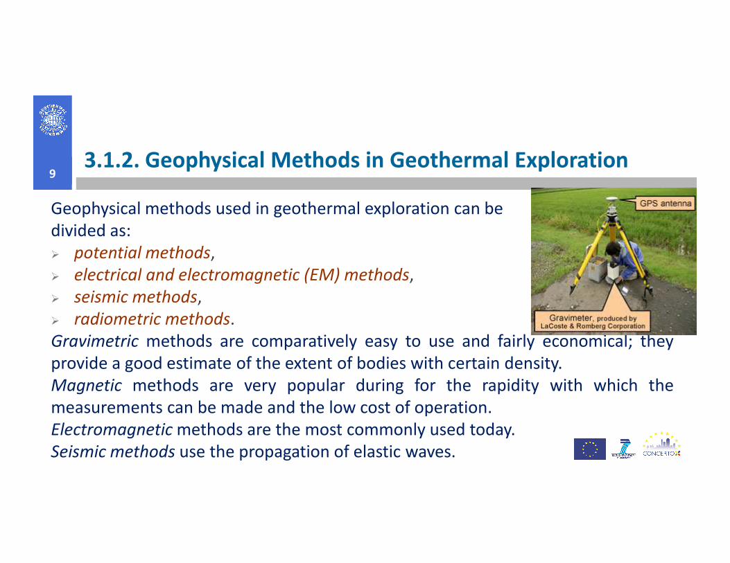
Geophysical methods used in geothermal exploration can be
divided as:
� potential methods,
� electrical and electromagnetic (EM) methods,� electrical and electromagnetic (EM) methods,
� seismic methods,
� radiometric methods.
Gravimetric methods are comparatively easy to use and fairly economical; they
provide a good estimate of the extent of bodies with certain density.
Magnetic methods are very popular during for the rapidity with which the
measurements can be made and the low cost of operation.
Electromagnetic methods are the most commonly used today.
Seismic methods use the propagation of elastic waves.

3.1.2. Geophysical Methods in Geothermal Exploration
10
Electromagnetic methods. Electro-
magnetic induction (EM), uses the
principle of induction to measure the
electrical conductivity of the subsurface.electrical conductivity of the subsurface.
Unlike conventional resistivity tech-
niques, no ground contact is required.
Electrical methods. Various methods for
measuring electrical resistivity are used
in geothermal exploration, based on the
premises that temperature affects the
electrical properties of rocks.

3.1.2. Geophysical Methods in Geothermal Exploration11
Magnetic methods. This is an
efficient and effective method to
survey large areas for under-
ground iron and steel objects such
as tanks and barrels.
3.1.2. Geophysical Methods in Geothermal Exploration
12
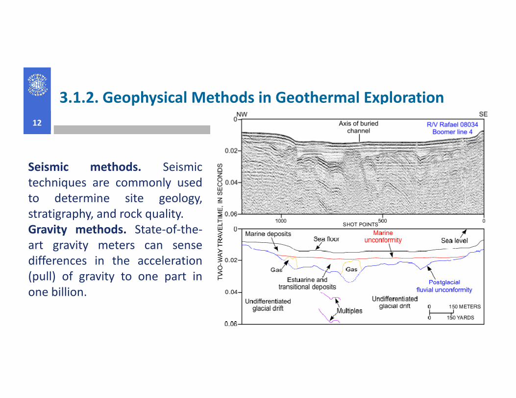
Seismic methods. Seismic
techniques are commonly used
to determine site geology,to determine site geology,
stratigraphy, and rock quality.
Gravity methods. State-of-the-
art gravity meters can sense
differences in the acceleration
(pull) of gravity to one part in
one billion.
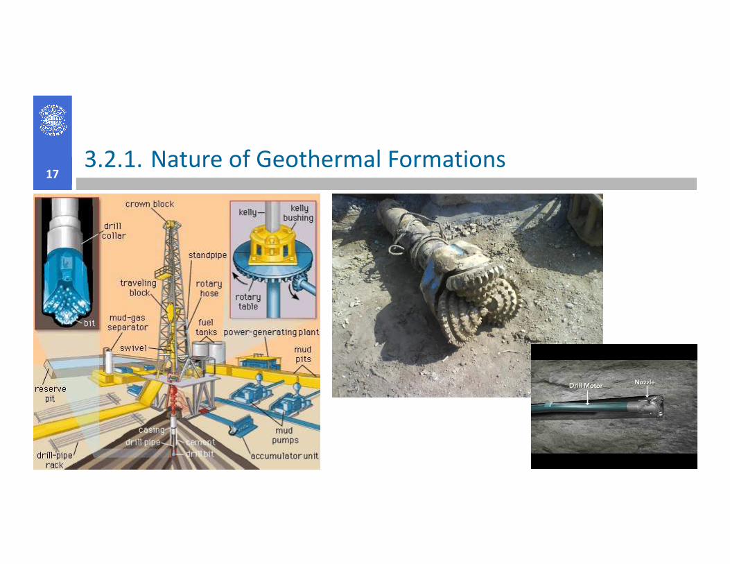
3.2. DRILLING AND COMPLETION 13
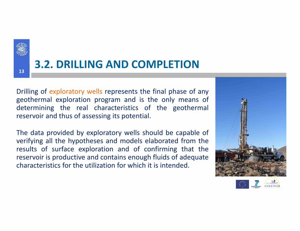
Drilling of exploratory wells represents the final phase of anygeothermal exploration program and is the only means ofdetermining the real characteristics of the geothermalreservoir and thus of assessing its potential.reservoir and thus of assessing its potential.
The data provided by exploratory wells should be capable ofverifying all the hypotheses and models elaborated from theresults of surface exploration and of confirming that thereservoir is productive and contains enough fluids of adequatecharacteristics for the utilization for which it is intended.

3.2.1. Nature of Geothermal Formations14
The geothermal formations are, by definition, hot (production intervals from 160°C
to above 300°C), often hard (240+ MPa compressive strength), abrasive (quartz
content above 50%), highly fractured (fracture apertures of centimeters), under-
pressured, often contain corrosive fluids, and some formation fluids have very highpressured, often contain corrosive fluids, and some formation fluids have very high
solids content (TDS in some Imperial Valley brines is above 250,000 ppm). These
conditions mean that drilling is usually difficult.
Common geothermal systems almost always contain dissolved or free CO2 and H2S
gases.
Depth and temperature of geothermal resources vary considerably.
3.2.1. Nature of Geothermal Formations15
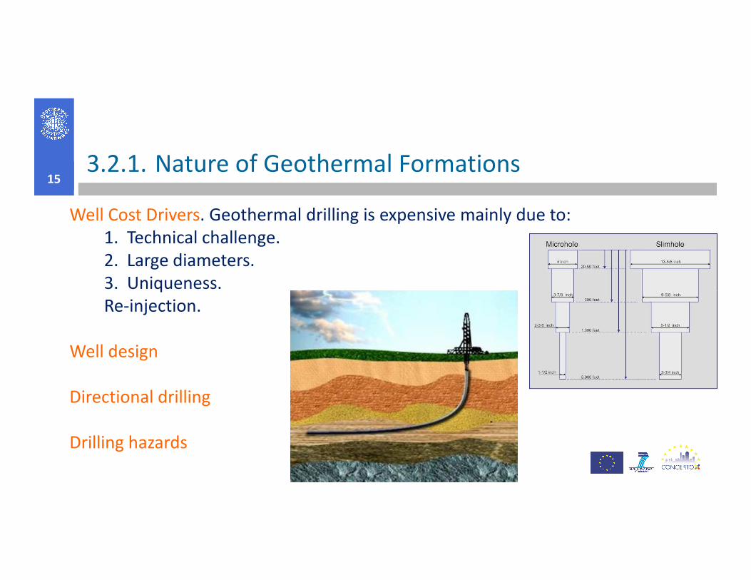
Well Cost Drivers. Geothermal drilling is expensive mainly due to:
1. Technical challenge.
2. Large diameters.
3. Uniqueness.3. Uniqueness.
Re-injection.
Well design
Directional drilling
Drilling hazards

3.2.1. Nature of Geothermal Formations16
Rate of penetration (ROP): Many of the costs attributed to drilling are time-dependent(primarily related to the rental rate on the rig and service company expenses), soanything that speeds up the hole advance without compromising safety, hole stability,or directional path is beneficial.
The 3 parameters that can be easily changed for any bit/formation combination areThe 3 parameters that can be easily changed for any bit/formation combination arerotary speed, weight on bit (WOB), and hydraulics (combination of jet size and flow rate)and it often takes some experimentation to determine the best combination of thesevalues.
Bit and tool life: Improved tool life means, that the expense of replacing a bit or otherpiece of equipment can be avoided or delayed, but there is also a time saving if trips canbe eliminated. The 3 factors that most affect bit and tool life are lithology, drillingparameters (including well path), and bottom-hole assembly design. The drillingengineer has little or no control over lithology, but significant improvements cansometimes be made by changes in the latter two factors.
3.2.1. Nature of Geothermal Formations17

3.2.2. Planning Geothermal Well18
There are two separate but closely related parts of preparing for a drillingproject:
� planning the well and
� designing the well.
“Planning” means to list, define, schedule, and budget for all themultitude of individual activities required to drill the well.
“Designing” means to specify all the physical parameters (depth,diameter, etc.) that define the well itself.
3.2.2. Planning Geothermal Well19
Drilling specification of an interval between two given depths and running casing:� Hole size and suggested bit type� Definition of all components of the bottom-hole assembly, and whether
downhole motors are to be used:� Expected rate of penetration and bit life,� Expected rate of penetration and bit life,� Any directional drilling instructions,� Drilling fluid type and flow rate.
� Any required logging during drilling or before casing is run,� Any required testing after cementing an interval of casing or at completion of
the well,� Size, weight, connection, and grade of casing, and whether it is a liner,� Proposed cementing program,� Any problems expected in that interval, or special precautions to be taken.

3.2.2. Planning Geothermal Well20
To begin designing of a well, a great variety of information is desirable, such are:
purpose of the well, surface or shallow hole conditions, reservoir conditions,
logistical requirements, likely problems in drilling, casing requirements.
Drill Rig Selection. Most of the criteria used to select a drill rig will be derived
from well parameters, specifically: diameter, depth, and casing design.
Several factors define the minimum hole diameter, and also bear upon whether
a core rig can be used for the hole: logging tools, core size, packers, flow test.

3.2.3. Classification of drilling methods 21
The drilling equipment is fed by energy, often obtained by diesel or electricaldriven motors and hydraulic loops.
By regarding the process of destruction, the cleaning of the borehole and the
forces applied on the drilling equipment, the most common drilling methods canforces applied on the drilling equipment, the most common drilling methods can
be described as:
� Cable tool drilling,
� Hammer drilling with air,
� Conventional Rotary Drilling,
� Auger drilling,
� Sonic drilling.

Cable tool drilling22
In China it was used for more than 2600 years ago. In Europe (for water supply) up
till the 1950-ies.
It was gradually replaced with the more efficient and much faster rotary drilling
methods.
Hammer drilling with airHammer drilling using pneumatic top hammers was introduced in the early last
century. At that time it was used for construction drilling.
In the 1970-ies hammer was introduced for water well drilling in hard rocks.
From then it is commonly used for drilling boreholes in crystalline rocks, as well as
in consolidated sedimentary rocks.
An advantage with hammer drilling is that the holes can be drilled directional.
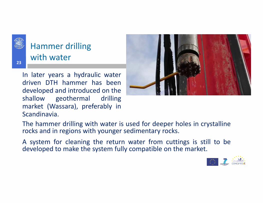
Hammer drilling
with water 23
In later years a hydraulic waterdriven DTH hammer has beendeveloped and introduced on theshallow geothermal drillingmarket (Wassara), preferably in
The hammer drilling with water is used for deeper holes in crystallinerocks and in regions with younger sedimentary rocks.
A system for cleaning the return water from cuttings is still to bedeveloped to make the system fully compatible on the market.
shallow geothermal drillingmarket (Wassara), preferably inScandinavia.
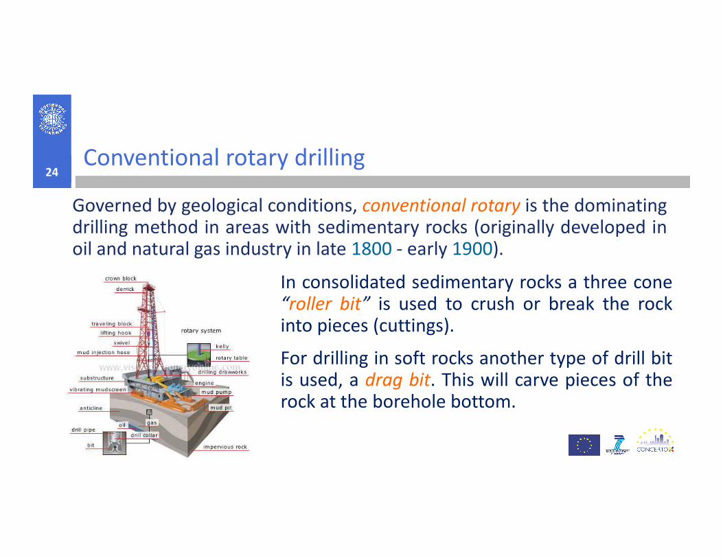
Conventional rotary drilling24
Governed by geological conditions, conventional rotary is the dominatingdrilling method in areas with sedimentary rocks (originally developed inoil and natural gas industry in late 1800 - early 1900).
In consolidated sedimentary rocks a three coneIn consolidated sedimentary rocks a three cone“roller bit” is used to crush or break the rockinto pieces (cuttings).
For drilling in soft rocks another type of drill bitis used, a drag bit. This will carve pieces of therock at the borehole bottom.

Conventional rotary drilling25
The rotary method has several advantages compared to hammerdrilling with air. The most pronounced one is that:� the borehole can be kept stable by the hydrostatic overpressure
that is created in the borehole compared to the hydrostaticpressure in the formation.that is created in the borehole compared to the hydrostaticpressure in the formation.
This is of course not the case if an artesian aquifer is reached.
On the other hand an obvious disadvantage is that:� the conventional rotary in hard rocks will be comparatively slow,
and in practice not even suitable for magmatic rock types.
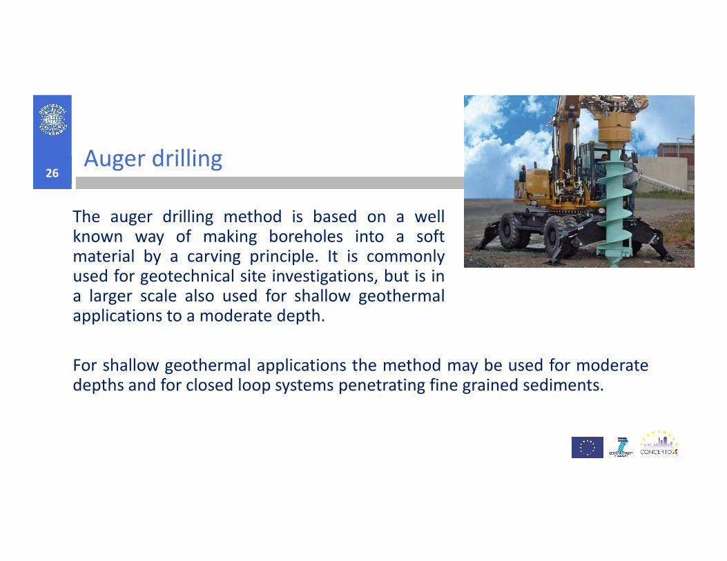
Auger drilling26
The auger drilling method is based on a wellknown way of making boreholes into a softmaterial by a carving principle. It is commonlyused for geotechnical site investigations, but is in
For shallow geothermal applications the method may be used for moderatedepths and for closed loop systems penetrating fine grained sediments.
used for geotechnical site investigations, but is ina larger scale also used for shallow geothermalapplications to a moderate depth.
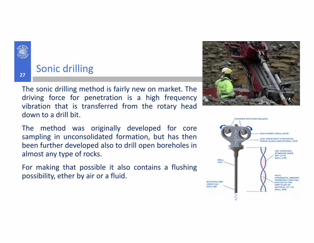
Sonic drilling27
The sonic drilling method is fairly new on market. Thedriving force for penetration is a high frequencyvibration that is transferred from the rotary headdown to a drill bit.
The method was originally developed for coresampling in unconsolidated formation, but has thenbeen further developed also to drill open boreholes inalmost any type of rocks.
For making that possible it also contains a flushingpossibility, ether by air or a fluid.

Sonic drilling28
Advantages of sonic drilling for geothermal installations:
� Fastest drilling method on earth.
� Ability to…
Economical drilling rates due to the efficient sonic drilling method, � Economical drilling rates due to the efficient sonic drilling method,
especially in gravel and boulder ground.
� Full length cased hole allows for:
� Steal casing is vibrating out of the ground after geo-loop installation and
placement of thermally enhanced grout.
� Cased borehole provides the ability to deal with free-flowing borehole or
artesian conditions.

3.2.4. Shallow geothermal drilling methods29
Shallow geothermal systems are commonly drilled to a depth of less
than 200 m and consist of boreholes for closed loop systems or wells
for open loop systems. All the methods mentioned in the
classification are in use for shallow
All the methods mentioned in the
classification are in use for shallow
boreholes; which one would be
applied at specific location depends
on the geological conditions and
available equipment, methods and
drilling procedures in the country.
3.2.5. Advanced geothermal drilling
technology30
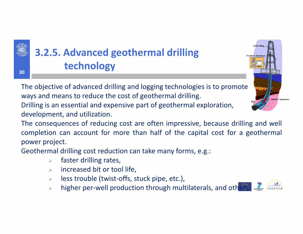
The objective of advanced drilling and logging technologies is to promote
ways and means to reduce the cost of geothermal drilling.
Drilling is an essential and expensive part of geothermal exploration,
development, and utilization. development, and utilization.
The consequences of reducing cost are often impressive, because drilling and well
completion can account for more than half of the capital cost for a geothermal
power project.
Geothermal drilling cost reduction can take many forms, e.g.:
� faster drilling rates,
� increased bit or tool life,
� less trouble (twist-offs, stuck pipe, etc.),
� higher per-well production through multilaterals, and others.

3.3. GEOHEAT EXTRACTION AND
PRODUCTION TECHNOLOGIES31
Thermal energy is extracted from the reservoir by coupled transport processes:
� convective heat transfer in porous and/or fractured regions of rock, and
� conduction through the rock itself.
Typically, hot water or steam is produced and its energy is converted into aTypically, hot water or steam is produced and its energy is converted into a
marketable product (electricity, process heat, or space heat).
Techniques for extracting heat from low-permeability hot dry rock (HDR) are:
� drill a well to sufficient depth to reach a useful temperature,
� create a large heat-transfer surface area by hydraulically fracturing the rock, and
intercept those fractures with a second well, and
� by circulating water from one well to the other through the stimulated region,
heat can be extracted from the rock.
3.3.1. Steam production32
Steam may be produced from:
� compressed liquid,
� two phase liquid/vapor or
� superheated vapor reservoirs.
Fluid may also change state during production further to pressure depletion.
In hole flashing. Most commercially developed fields are of the liquid
dominated type and are likely more to two phases during exploitation above a
230°C temperature.
Well bore flashing may cause scaling shortcomings by precipitation, above the
flash front, of calcium carbonates for instance, whenever the well head
pressure is depleted below CO2 partial pressure.

3.3.1. Steam production33
Vapor/liquid separation is completed by cylindrical vessels of either the verticalor horizontal type. Both apply a forced vortex principle.
The vertical separator is based on streamlined inlet fluid admission andcentrifugal steam separation whereas in the horizontal outfit the fluid enterstangentially and the steam is recovered by gravity.centrifugal steam separation whereas in the horizontal outfit the fluid enterstangentially and the steam is recovered by gravity.
A reasonable compromise would consist of dedicating vertical units to, firststage, high pressure separation and horizontal vessels to, second stage, lowpressure separation.
The quality of the steam is controlled by the liquid level in the separator(s).
Steam needs to be kept dry, almost 100%, to avoid carryover of water dropletsand subsequent mechanical (impact) and chemical (scaling) damage to turbineblades and ancillary equipment.
3.3.1. Steam production34
Non condensable gases. Carbon dioxide, a major constituent in geothermalvapor, affects brine thermo chemistry turbine efficiency and steam condensing.
Depending on non condensable gas content two extraction systems may becontemplated, a part from pre-flashing, ejectors and compressors respectively.contemplated, a part from pre-flashing, ejectors and compressors respectively.
Ejectors display poor efficiencies (15%) and require 12% of the steam mass flowavailable at well head to extract 1% (vol) of non condensable gases.
Higher gas volumes require, because of low inlet pressure, large multistagecompressors, with compression rates as high as 8 and high (80%) efficiencies andrelated costs.
Consumption amounts to 3% (mass) of well head vapor flow per 1% (vol) of CO2.
3.3.1. Steam production35
Waste water disposal. Assuming a 250°C, 40 bar fluid pressure, i.e. a singlephase compressed liquid state at reservoir conditions, a 7 bar turbine inletpressure, a 50 MWe rated geoelectric plant with a 20% conversionefficiency, the waste water discharge rate would amount to cca 4200 m3/h.efficiency, the waste water discharge rate would amount to cca 4200 m /h.
Therefore, waste disposal and environmental consequences become amajor concern, to which, water injection, seems the most relevantremedial solution.
A superheated steam field would not face such constraints, the sole liquidwaste consisting of steam condensates.
3.3.2. Hot water production36
The circulation of hot water from the well can be either:
� self-flowing or
� artificial lift (forced circulation with pump).
Self flowing is by far the most attractive production mode provided it canSelf flowing is by far the most attractive production mode provided it can
supply target flow rates without excessively depleting well head pressures,
in which case adequate degassing/gas abatement facilities would be
required.
Therefore artificial lift is most often the rule in geothermal, low grade heat,
direct uses. It is best achieved thanks to the three submersible pumping
alternatives: line shaft, electro submersible, turbine respectively.
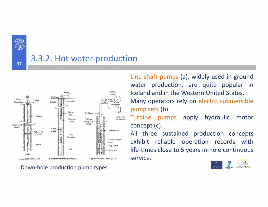
3.3.2. Hot water production37
Line shaft pumps (a), widely used in ground
water production, are quite popular in
Iceland and in the Western United States.
Many operators rely on electro submersible
Down-hole production pump types
Many operators rely on electro submersible
pump sets (b).
Turbine pumps apply hydraulic motor
concept (c).
All three sustained production concepts
exhibit reliable operation records with
life-times close to 5 years in-hole continuous
service.

3.3.3. Deep borehole heat exchangers
(ground source heat exchangers)38
Deep borehole heat exchangers have been installed to depthsof about 1500 m – 3000 m and maximum temperatures ofabout 60°C – 110°C.
In contrast to shallow borehole heat exchangers, U-pipesIn contrast to shallow borehole heat exchangers, U-pipescannot be used due to the much greater depth of theboreholes.
These systems consist of a coaxial arrangement of an innerproduction pipe inserted into an outer borehole casing.
Deep borehole heat exchangers indicate a specific power ofabout 20– 54 W·m-1, similar to that of shallow systems.

3.4. ENHANCED GEOTHERMAL SYSTEMS39
The term enhanced geothermal systems (EGS), refers to a variety of engineeringtechniques used to artificially create hydrothermal resources that can be used togenerate electricity.
Traditional geothermal plants exploit naturally occurring hydrothermal reservoirs.
EGS technologies use the heat of the earth’s crust to generate electricity.
EGS, attempts to artificially reproduce the conditions of naturally occurring
hydrothermal reservoirs by fracturing impervious hot rocks at 3 to 10 kilometers
depth, pumping fluid into the newly porous system, and then extracting the heated
fluid to drive an electricity-generating turbine.
An EGS is a man-made reservoir, created where there is hot rock but insufficient or
little natural permeability or fluid saturation.

40

3.4.1. Current EGS drilling technology41
Fluid temperatures in excess of 190°C may damage components such asseals and elastomeric insulators. Bit-bearing seals, cable insulations, surfacewell-control equipment, and sealing elements are some of the items thatmust be designed and manufactured with these temperatures in mind.must be designed and manufactured with these temperatures in mind.
Logging. The use of well logs is an important diagnostic tool that is not yetfully developed in the geothermal industry.
Thermal expansion of casing. Thermal expansion can cause buckling of thecasing and casing collapse, which can be costly.
Drilling fluids/“mud” coolers. Surface “mud coolers” are commonly used toreduce the temperature of the drilling fluid before it is pumped back downthe hole.

3.4.1. Current EGS drilling technology42
Drill bits and increased rate of penetration. Many EGS resources are in formations
that are igneous, influenced by volcanic activity, or that have been altered by high
temperatures and/or hot fluids.
Drilling in these formations is generally more difficult.
However, not all geothermal formations are slow to drill. Many are drilledHowever, not all geothermal formations are slow to drill. Many are drilled
relatively easily overall, with isolated pockets of hard, crystalline rock. In these
conditions, drill bit selection is critical.
Lost circulation. Lost circulation is a drilling problem that arises when the
circulation of the drilling fluid is interrupted and it does not return to the surface.
The drilling fluid must be mixed and pumped fast enough to sustain flow and keep
the bit clean, which can be an expensive process.

3.4.1. Current EGS drilling technology43
Directional drilling. Directionally drilled wells reach out in differentdirections and permit production from multiple zones that cover a greaterportion of the resource and intersect more fractures through a singlecasing.casing.
An EGS power plant typically requires more than one production well. Interms of the plant design, and to reduce the overall plant “footprint,” it ispreferable to have the wellheads close to each other.
Directional drilling permits this while allowing production well bottom-spacing’s of 900 m or more.