geotechnical pavement evaluation palm - · pdf filegroundwater was not encountered in our...
TRANSCRIPT

GEOTECHNICAL PAVEMENT EVALUATION PALM AVENUE AND
PALOMAR STREET STATIONS BLUE LINE LRT STATION IMPROVEMENTS
SAN DIEGO AND CHULA VISTA, CALIFORNIA
PREPARED FOR: Kimley-Horn
401 B Street, Suite 600 San Diego, California 92101
PREPARED BY: Ninyo & Moore
Geotechnical and Environmental Sciences Consultants 5710 Ruffin Road
San Diego, California 92123
December 6, 2011 Project No. 104804045

December 6, 2011 Project No. 104804045
Mr. Anthony Podegracz, P.E. Kimley-Horn 401 B Street, Suite 600 San Diego, California 92101
Subject: Geotechnical Pavement Evaluation Palm Avenue and Palomar Street Stations Blue Line LRT Station Improvements San Diego and Chula Vista, California
Dear Mr. Podegracz:
In accordance with your request and authorization, we have performed a geotechnical evaluation for the proposed parking lot improvements for the Palm Avenue and Palomar Street stations lo-cated in San Diego and Chula Vista, California. This report presents our geotechnical findings, conclusions, and recommendations regarding the proposed project.
We appreciate the opportunity to be of service on this project.
Sincerely, NINYO & MOORE
Chet Robinson, PE, GE Senior Project Engineer
Soumitra Guha, PhD, PE, GE Principal Engineer
Jonathan Goodmacher, PG, CEG Manager/Principal Geologist
MBG/CER/SG/JG/gg
Distribution: (1) Addressee (via e-mail)

Palm Avenue and Palomar Street Stations December 6, 2011 Blue Line LRT Station Improvements Project No. 104804045 San Diego and Chula Vista, California
104804045 R Pavement Eval.doc i
TABLE OF CONTENTS Page
1. INTRODUCTION ....................................................................................................................1
2. SCOPE OF SERVICES............................................................................................................1
3. SITE AND PROJECT DESCRIPTION ...................................................................................2
4. PREVIOUS GEOTECHNICAL EVALUATION....................................................................2
5. SUBSURFACE EXPLORATION AND LABORATORY TESTING....................................3
6. GEOLOGY AND SUBSURFACE CONDITIONS .................................................................3 6.1. Subsurface Conditions ..................................................................................................3
6.1.1. Pavement Structural Sections..............................................................................3 6.1.2. Fill .......................................................................................................................4 6.1.3. Old Paralic Deposits............................................................................................4
6.2. Groundwater .................................................................................................................4
7. DISCUSSION...........................................................................................................................5
8. CONCLUSIONS ......................................................................................................................6
9. RECOMMENDATIONS..........................................................................................................6 9.1. Earthwork .....................................................................................................................7
9.1.1. Site Preparation ...................................................................................................7 9.1.2. Excavation Characteristics ..................................................................................7 9.1.3. Remedial Grading ...............................................................................................7 9.1.4. Materials for Fill .................................................................................................8 9.1.5. Compacted Fill ....................................................................................................8 9.1.6. Temporary Excavations, Braced Excavations, and Shoring ...............................9 9.1.7. Utility Trench Backfill ......................................................................................10
9.2. Pavements ...................................................................................................................10 9.3. Drainage......................................................................................................................12 9.4. Pre-Construction Conference......................................................................................13 9.5. Plan Review and Construction Observation ...............................................................13
10. LIMITATIONS.......................................................................................................................13
11. REFERENCES .......................................................................................................................15
Palm Avenue and Palomar Street Stations December 6, 2011 Blue Line LRT Station Improvements Project No. 104804045 San Diego and Chula Vista, California
104804045 R Pavement Eval.doc ii
Tables Table 1 – Encountered Pavement Sections ......................................................................................4 Table 2 – Pavement TIs after Replacement of Upper 3 inches of Asphalt Concrete ...............................11 Table 3 – Pavement TIs for New Asphalt Concrete Pavements ....................................................12
Figures Figure 1 – Project Location Figure 2A – Boring Locations - Palm Avenue Station Figure 2B – Boring Locations - Palomar Street Station
Appendices Appendix A – Boring Logs Appendix B – Laboratory Testing

Palm Avenue and Palomar Street Stations December 6, 2011 Blue Line LRT Station Improvements Project No. 104804045 San Diego and Chula Vista, California
104804045 R Pavement Eval.doc 1
1. INTRODUCTION
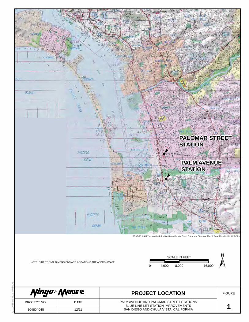
In accordance with your request, we have performed a geotechnical pavement evaluation for se-
lected areas of the parking lots at the Palm Avenue and Palomar Street stations located in
San Diego and Chula Vista (Figure 1). This report presents the results of our field exploration and
laboratory testing, our conclusions regarding the geotechnical conditions at the subject site, and our
recommendations for pavement design and earthwork construction of this project.
2. SCOPE OF SERVICES
The scope of services for this study included the following:
Coordinating with the Metropolitan Transit System (MTS), San Diego Association of Gov-ernments (SANDAG) personnel, and Kimley-Horn to identify suitable locations for our subsurface explorations.
Reviewing background data listed in the References section of this report. The data reviewed included topographic maps, geologic data, stereoscopic aerial photographs, fault maps, and a site plan of the site.
Performing a field reconnaissance to observe current site conditions and to locate and mark proposed exploratory borings.
Notifying Underground Service Alert and Cable Pipe and Leak Detection in order to clear subsur-face exploration locations of potential conflicts with underground utilities as required by MTS.
Coring the existing asphalt pavements at two locations for each station (total of four cores). Core locations were selected by Kimley-Horn.
Drilling, logging, and sampling of four shallow exploratory borings with hand auger equipment at the cored locations. The aggregate base thicknesses were evaluated and subgrade soil samples were collected. Soil samples were transported to our in-house geotechnical laboratory for analysis.
Performing geotechnical laboratory testing on selected soil samples obtained from our subsur-face explorations to evaluate R-value and gradation.
Compiling and analyzing the engineering data obtained from our background, laboratory, and field evaluations.
Preparing this report presenting our findings, conclusions, and recommendations regarding the proposed pavement reconstruction at the stations.

Palm Avenue and Palomar Street Stations December 6, 2011 Blue Line LRT Station Improvements Project No. 104804045 San Diego and Chula Vista, California
104804045 R Pavement Eval.doc 2
3. SITE AND PROJECT DESCRIPTION
The Palm Avenue and Palomar Street stations are active light rail transit (LRT) trolley stations
along the current Blue Line route located in Chula Vista and San Diego, California (Figure 1). The
stations generally consist of concrete slabs abutting the tracks for the loading and unloading of pas-
sengers. Asphalt concrete (AC) paved parking lots are present adjacent to each station. The station
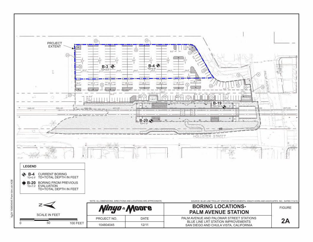
parking areas are generally flat. The Palm Avenue station is located at the intersection of Palm
Avenue and Hollister Street and is approximately 44 to 46 feet above mean sea level (MSL). The
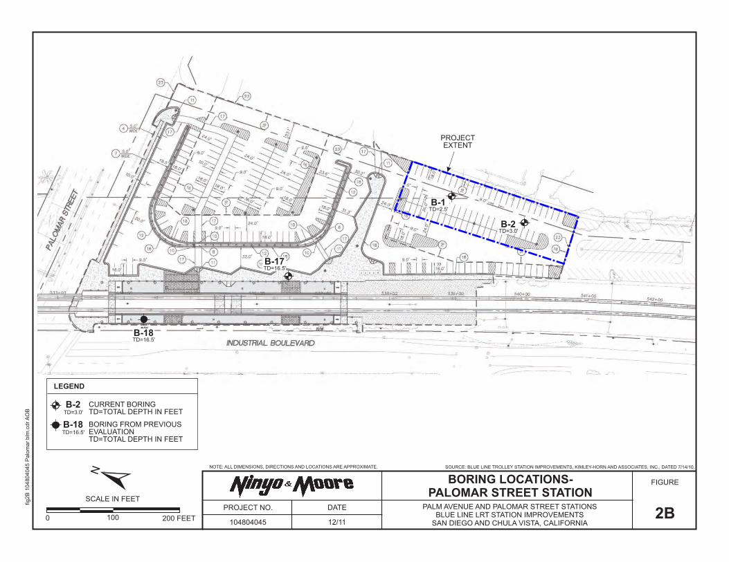
Palomar Street station is located at the intersection of Palomar Street and Industrial Boulevard and
is approximately 50 to 54 feet above MSL.
We understand that the conclusions and recommendations of our evaluation will be used in the reha-
bilitation of selected areas of the parking lots. The areas to be rehabilitated are shown on Figures 2A
and 2B. Additional improvements may include the installation of new underground utility lines.
4. PREVIOUS GEOTECHNICAL EVALUATION
Ninyo & Moore previously conducted a geotechnical evaluation for the improvement to various
stations along the Blue Line. The results were presented in our March 3, 2011 geotechnical evalua-
tion report (referenced). The evaluation at Palm Avenue Station was performed for improvements
consisting of raised platforms and new shelters. The evaluation at Palomar Street Station was per-
formed for improvements consisting of raised platforms, new shelters, and retaining walls. The
subsurface explorations for these stations were performed on November 16 and 19, 2010, and con-
sisted of the drilling, logging, and sampling of two small-diameter exploratory borings at each
station on the adjacent trolley station platform areas. The borings were drilled to depths of ap-
proximately 7 to 16½ feet below the existing ground surface with a limited-access drill rig.

Palm Avenue and Palomar Street Stations December 6, 2011 Blue Line LRT Station Improvements Project No. 104804045 San Diego and Chula Vista, California
104804045 R Pavement Eval.doc 3
5. SUBSURFACE EXPLORATION AND LABORATORY TESTING
Our subsurface exploration was conducted on October 4 and 7, 2011, and consisted of the drill-
ing, logging, and sampling of two small-diameter exploratory borings at each station (total of
four borings). A coring machine was used to drill through the AC pavement, and a hand auger
was then used to drill and obtain samples of the subgrade soils. The samples were transported to
our in-house geotechnical laboratory for testing. The approximate locations of the exploratory
borings are shown on Figures 2A and 2B. Logs of the recent and previous borings are included in
Appendix A. Recent laboratory testing of representative soil samples included gradation and R-
value analyses. The results of these and previous laboratory tests are presented in Appendix B.
6. GEOLOGY AND SUBSURFACE CONDITIONS
Our findings regarding geologic and groundwater conditions at the subject sites, are provided in
the following sections.
6.1. Subsurface Conditions
Materials encountered during our subsurface evaluation include pavement structural sec-
tions, fill, and old paralic deposits. Generalized descriptions of the materials encountered are
provided in the subsequent sections. Additional descriptions are provided on the boring logs in
Appendix A.
6.1.1. Pavement Structural Sections
In general, during our subsurface exploration in the pavement areas we encountered
pavement sections that consisted of asphalt concrete generally underlain by approxi-
mately 4 to 6 inches of base. Laboratory sieve analysis on two samples of the base
material indicate that they do not meet the grading requirements for Class 2 Aggregate
Base in Section 26 of the Caltrans Standard Specifications, but they do meet the grading
requirements in Section 25 for Aggregate Subbase (Caltrans, 2006b). The following ta-
ble presents a summary of the encountered structural sections.

Palm Avenue and Palomar Street Stations December 6, 2011 Blue Line LRT Station Improvements Project No. 104804045 San Diego and Chula Vista, California
104804045 R Pavement Eval.doc 4
Table 1 – Encountered Pavement Sections
Boring No.
Station Encountered AC
Thickness (in) Encountered ASB*
Thickness (in) B-1 Palomar Street 4 6 B-2 Palomar Street 3 ¾ 4 ½ B-3 Palm Avenue 3 ½ 5 ½ B-4 Palm Avenue 3 ¾ 4
*ASB = Aggregate Subbase
6.1.2. Fill
In the pavement cores, fill was encountered in our recent borings from beneath the
pavement and aggregate subbase to depths of up to approximately 3 feet. As encoun-
tered, the fill generally consisted of damp to moist, medium dense, silty and clayey sand
or sandy silt, with scattered gravel and asphalt concrete debris.
In the borings drilled during our previous investigation, fill was encountered up to a depth
of approximately 1 foot at the Palm Avenue Station and to a depth of up to approximately
11 feet at the Palomar Street Station. The fill material varied between the stations, but gen-
erally consisted of moist to wet, loose to dense, silty and clayey sand, or firm to stiff, sandy
clay, with fine to coarse gravel, trace cobbles, and scattered trash and wood fragments.
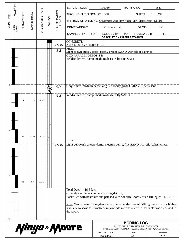
6.1.3. Old Paralic Deposits
In borings drilled during this (B-2 at Palomar Station) and our previous investigation,
old paralic deposits were encountered below the fill. The old paralic deposits from this
investigation generally consisted of damp to moist, medium dense to dense, silty and
clayey sand, with silt, gravel and cobbles.
6.2. Groundwater
Groundwater was not encountered in our recent or previous exploratory borings. Fluctua-
tions in the groundwater level and local perched conditions may occur due to variations in
ground surface topography, subsurface geologic conditions and structure, rainfall, irrigation,
and other factors.
Palm Avenue and Palomar Street Stations December 6, 2011 Blue Line LRT Station Improvements Project No. 104804045 San Diego and Chula Vista, California
104804045 R Pavement Eval.doc 5
7. DISCUSSION
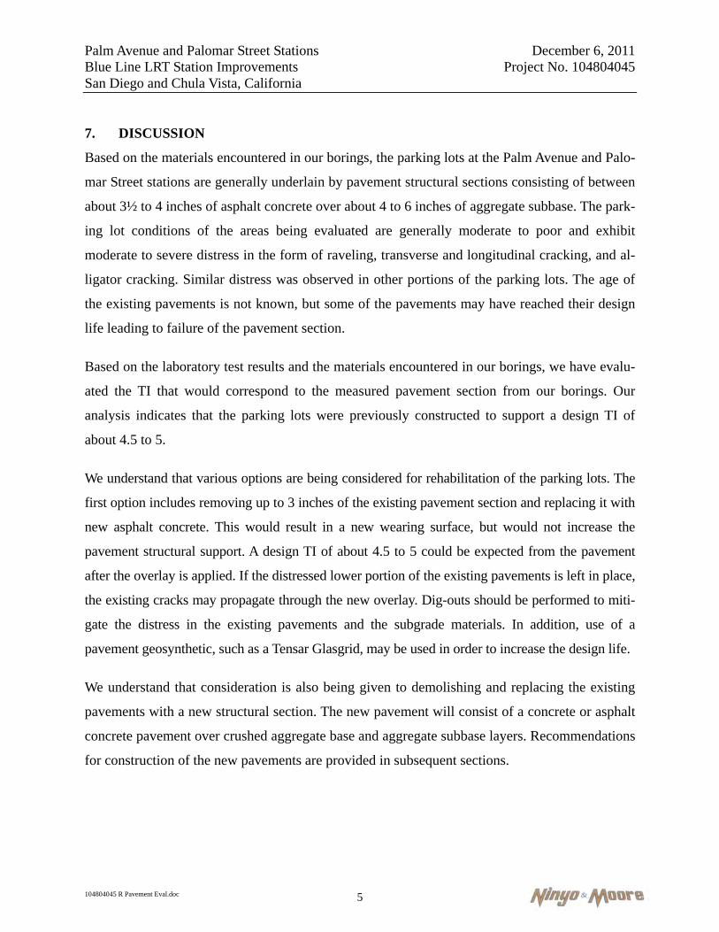
Based on the materials encountered in our borings, the parking lots at the Palm Avenue and Palo-
mar Street stations are generally underlain by pavement structural sections consisting of between
about 3½ to 4 inches of asphalt concrete over about 4 to 6 inches of aggregate subbase. The park-
ing lot conditions of the areas being evaluated are generally moderate to poor and exhibit
moderate to severe distress in the form of raveling, transverse and longitudinal cracking, and al-
ligator cracking. Similar distress was observed in other portions of the parking lots. The age of
the existing pavements is not known, but some of the pavements may have reached their design
life leading to failure of the pavement section.
Based on the laboratory test results and the materials encountered in our borings, we have evalu-
ated the TI that would correspond to the measured pavement section from our borings. Our
analysis indicates that the parking lots were previously constructed to support a design TI of
about 4.5 to 5.
We understand that various options are being considered for rehabilitation of the parking lots. The
first option includes removing up to 3 inches of the existing pavement section and replacing it with
new asphalt concrete. This would result in a new wearing surface, but would not increase the
pavement structural support. A design TI of about 4.5 to 5 could be expected from the pavement
after the overlay is applied. If the distressed lower portion of the existing pavements is left in place,
the existing cracks may propagate through the new overlay. Dig-outs should be performed to miti-
gate the distress in the existing pavements and the subgrade materials. In addition, use of a
pavement geosynthetic, such as a Tensar Glasgrid, may be used in order to increase the design life.
We understand that consideration is also being given to demolishing and replacing the existing
pavements with a new structural section. The new pavement will consist of a concrete or asphalt
concrete pavement over crushed aggregate base and aggregate subbase layers. Recommendations
for construction of the new pavements are provided in subsequent sections.

Palm Avenue and Palomar Street Stations December 6, 2011 Blue Line LRT Station Improvements Project No. 104804045 San Diego and Chula Vista, California
104804045 R Pavement Eval.doc 6
8. CONCLUSIONS
Based on our review of the referenced background data, subsurface evaluation, and laboratory
testing, it is our opinion that pavement reconstruction for these projects is feasible from a geo-
technical standpoint provided the recommendations presented in this report are incorporated into
the design and construction of the projects. In general, the following conclusions were made:
The project sites are generally underlain by fill soils over old paralic deposits.
Groundwater was not encountered at these sites. Groundwater is not anticipated to be a de-sign consideration during reconstruction of the parking lots.
The fill materials and old paralic deposits should be generally excavatable with heavy-duty earth moving equipment in good working condition.
The existing asphalt concrete within the areas of evaluation for the parking lots exhibits mod-erate to severe distress in the form of surface raveling, longitudinal and transverse cracks, and alligator cracking. Based on our geotechnical evaluation and the condition of the existing pavements, it is our opinion that some of the existing pavement sections have exceeded their design life or are structurally inadequate for the support of the current traffic loading.
Existing fill soils in the parking lots may be loose/soft, potentially compressible or wet, and may be inadequate for the support of new pavement structural sections. Further evaluation would be appropriate prior to or at the time of site grading to evaluate methods of remediat-ing the subgrade soil conditions based on the materials encountered.
Soils derived from the on-site excavations may be clayey in nature and in a condition above optimum moisture content to wet. Drying of these materials should be anticipated before they can be reused as compacted fill.
9. RECOMMENDATIONS
Based on our understanding of the project, the following recommendations are provided for the
design and construction of the new pavements. The proposed new pavements should be con-
structed in accordance with the requirements of the applicable governing agencies.

Palm Avenue and Palomar Street Stations December 6, 2011 Blue Line LRT Station Improvements Project No. 104804045 San Diego and Chula Vista, California
104804045 R Pavement Eval.doc 7
9.1. Earthwork
In general, earthwork should be performed in accordance with the recommendations pre-
sented in this report. The geotechnical consultant should be contacted for questions
regarding the recommendations or guidelines presented herein.
9.1.1. Site Preparation
Site preparation should begin with the removal of vegetation, utility lines, asphalt,
concrete, and other deleterious debris from areas to be graded. Tree stumps and roots
should be removed to such a depth that organic material is generally not present.
Clearing and grubbing should extend to the outside of the proposed excavation and fill
areas. The debris and unsuitable material generated during clearing and grubbing
should be removed from areas to be graded and disposed of at a legal dumpsite away
from the project area.
9.1.2. Excavation Characteristics
The results of our field exploration indicate that the project sites, as presently proposed, are
underlain by fill soils and old paralic deposits. The fill and old paralic deposit materials
should be generally excavatable with standard earth moving equipment.
9.1.3. Remedial Grading
To create a uniform bearing surface for parking lot pavements, we recommend that the
existing fill soils be overexcavated to provide an 18-inch-thick zone of compacted fill be-
low the planned subgrades. If a reinforcing geogrid, such as a Mirafi BXG12 or
equivalent, is placed beneath the fill, the overexcavation may be reduced to provide a
12-inch thick zone of compacted fill below the planned subgrades.
The extent and depths of removals should be evaluated by Ninyo & Moore’s representa-
tive in the field based on the materials exposed. Additional remedial grading may be
required depending on the exposed materials. The contractor should take precautionary
measures not to damage the existing improvements.

Palm Avenue and Palomar Street Stations December 6, 2011 Blue Line LRT Station Improvements Project No. 104804045 San Diego and Chula Vista, California
104804045 R Pavement Eval.doc 8
9.1.4. Materials for Fill
On-site soils with an organic content of less than approximately 3 percent by volume (or
1 percent by weight) are suitable for use as fill. In general, fill material should not con-
tain rocks or lumps over approximately 3 inches in diameter, and not more than
approximately 30 percent larger than ¾ inch. The on-site materials may generate cob-
bles larger than 4 inches in diameter. Oversize materials should be separated from
material to be used for fill and removed from the site.
Utility trench backfill material should not contain rocks or lumps over approximately
3 inches in general. Soils classified as silts or clays should not be used for backfill in the
pipe zone. Larger chunks, if generated during excavation, may be broken into accepta-
bly sized pieces or disposed of offsite.
Imported fill material, if needed for the project, should generally be granular soils with a
low expansion potential (i.e., an expansion index [EI] of 50 or less as evaluated by ASTM
International [ASTM] Test Method D 4829). Import material should also be non-corrosive
in accordance with the Caltrans (2003) corrosion guidelines. Materials for use as fill should
be evaluated by Ninyo & Moore’s representative prior to filling or importing.
9.1.5. Compacted Fill
Prior to placement of compacted fill, the contractor should request an evaluation of the
exposed ground surface by Ninyo & Moore. Unless otherwise recommended, the ex-
posed ground surface should then be scarified to a depth of approximately 8 inches and
moisture conditioned by wetting or aeration to generally near the optimum moisture
content. The scarified materials should then be compacted to 90 percent of their modi-
fied Proctor density as evaluated by ASTM D 1557. The evaluation of compaction by
the geotechnical consultant should not be considered to preclude any requirements for
observation or approval by governing agencies. It is the contractor's responsibility to
notify this office and the appropriate governing agency when project areas are ready for
observation, and to provide reasonable time for that review.

Palm Avenue and Palomar Street Stations December 6, 2011 Blue Line LRT Station Improvements Project No. 104804045 San Diego and Chula Vista, California
104804045 R Pavement Eval.doc 9
Fill materials should be moisture conditioned to generally near the laboratory optimum moisture
content prior to placement. The optimum moisture content will vary with material type and other
factors. Moisture conditioning of fill soils should be generally consistent within the soil mass.
Prior to placement of additional compacted fill material following a delay in the grading
operations, the exposed surface of previously compacted fill should be prepared to receive
fill. Preparation may include scarification, moisture conditioning, and recompaction.
Compacted fill should be placed in horizontal lifts of approximately 8 inches in loose
thickness. Prior to compaction, each lift should be watered or dried as needed to achieve a
moisture content generally near the laboratory optimum, mixed, and then compacted by
mechanical methods to 90 percent of its modified Proctor density as evaluated by ASTM
D 1557. The upper 12 inches below the pavement subgrade should be compacted to
95 percent of its modified Proctor density as evaluated by ASTM D 1557. Successive lifts
should be treated in a like manner until the desired finished grades are achieved.
9.1.6. Temporary Excavations, Braced Excavations, and Shoring
For temporary excavations, we recommend that the following Occupational Safety and
Health Administration (OSHA) soil classifications be used:
Fill and Old Paralic Deposits Type C
Upon making the excavations, the soil classifications and excavation performance
should be evaluated in the field by a competent person in accordance with the OSHA
regulations. Temporary excavations should be constructed in accordance with OSHA
recommendations. For trench or other excavations, OSHA requirements regarding per-
sonnel safety should be met using appropriate shoring (including trench boxes) or by
laying back the slopes to no steeper than 1.5:1 (horizontal to vertical) in fill and old
paralic deposit materials. Temporary excavations that encounter seepage may be shored
or stabilized by placing sandbags or gravel along the base of the seepage zone. Excava-
tions encountering seepage should be evaluated on a case-by-case basis. On-site safety
of personnel is the responsibility of the contractor.

Palm Avenue and Palomar Street Stations December 6, 2011 Blue Line LRT Station Improvements Project No. 104804045 San Diego and Chula Vista, California
104804045 R Pavement Eval.doc 10
9.1.7. Utility Trench Backfill
Based on our subsurface evaluation, the on-site earth materials should be generally suit-
able for re-use as trench backfill provided they are free of organic material, clay lumps,
debris, and rocks greater than approximately 3 inches in diameter. Fill should be mois-
ture-conditioned to generally near the laboratory optimum. Trench backfill should be
compacted to 90 percent of its modified Proctor density as evaluated by ASTM D 1557
except for the upper 12 inches of the backfill in pavement areas which should be com-
pacted to 95 percent of its modified Proctor density as evaluated by ASTM D 1557. Lift
thickness for backfill will depend on the type of compaction equipment utilized, but fill
should generally be placed in lifts not exceeding 8 inches in loose thickness. Special
care should be exercised to avoid damaging the pipe during compaction of the backfill.
9.2. Pavements
We understand that two options are being considered for rehabilitation of selected areas
within the parking lots at the Palm Avenue and Palomar Street stations. The first option in-
cludes removing up to 3 inches of the existing pavement section and replacing it with new
asphalt concrete. The second option being considered includes replacing the existing pave-
ments with a new structural section. The new structural sections are taken from the
SANDAG Design Criteria (SANDAG, 2009) and the Pavement Details plan by Kim-
ley-Horn (Kimley-Horn, 2011).
The subgrade soils were tested at each of the stations for R-value to evaluate their pavement
support characteristics. An additional R-value test at the Palomar station was conducted dur-
ing our previous evaluation. The materials tested include silty sands and clayey sands from
the existing fill materials. The test results indicated R-values between 17 and 21 for the
clayey sands and 52 for the silty sands. Based on the anticipated variability of the on-site
soils, we have used a design R-value of 20 at the Palm Avenue station and an R-value of 15
at the Palomar Street station.

Palm Avenue and Palomar Street Stations December 6, 2011 Blue Line LRT Station Improvements Project No. 104804045 San Diego and Chula Vista, California
104804045 R Pavement Eval.doc 11
Based on the tested subgrade R-values and the pavement section thicknesses measured in
our borings, we have evaluated (i.e., back calculated) the equivalent TI that would corre-
spond to removing the upper 3 inches of the existing pavement and replacing it with new
asphalt concrete. The estimated TIs are presented in Table 2.
Table 2 – Pavement TIs after Replacement of Upper 3 inches of Asphalt Concrete
Station Encountered Pavement
Structural Section Design Subgrade
R-Value Back-Calculated TI
Palm Avenue 3.5” AC over 5.5” ASB* (Boring B-3) 20 4.5
Palm Avenue 3.75” AC over 4” ASB (Boring B-4) 20 4.5
Palomar Street 4” AC over 6” ASB (Boring B-1) 15 5.0
Palomar Street 3.75” AC over 4.5” ASB (Boring B-2) 15 4.5
Dig-outs should be performed to mitigate distress in the existing pavements and the sub-
grade materials. In addition, use of a pavement geosynthetic, such as a Tensar Glasgrid, may
be used in order to increase the design life.
To rehabilitate the existing parking lots, the second option includes demolishing and replac-
ing the existing pavements with a new structural section. The new pavement will consist of
either a Portland cement concrete (PCC) pavement or an AC pavement over crushed aggre-
gate base and aggregate subbase layers. We understand that the PCC pavement will consist
of 9 inches of concrete over 12 inches of aggregate base and 6 inches of aggregate subbase
over the compacted fill subgrade. The concrete should be designed with a flexural strength
of 600 pounds per square inch or more. Pavement joints should be constructed as detailed by
the project structural engineer.
Based upon the existing subgrade conditions at the stations, we have evaluated the antici-
pated design TI that would correspond to the asphalt concrete pavement sections provided in
the Pavement Details plan by Kimley-Horn (Kimley-Horn, 2011). The plan includes pave-
ment sections designated as Heavy Duty, Light Duty, and 10-foot Access Drives. The
anticipated TIs for the proposed pavements at the stations are summarized in Table 3.

Palm Avenue and Palomar Street Stations December 6, 2011 Blue Line LRT Station Improvements Project No. 104804045 San Diego and Chula Vista, California
104804045 R Pavement Eval.doc 12
Table 3 – Pavement TIs for New Asphalt Concrete Pavements
Station Proposed Pavement Design Subgrade
R-Value Back-Calculated TI
Palm Avenue Heavy Duty 6” AC over 8” AB* over 6” ASB 20 8.5
Palm Avenue Light Duty 6” AC over 4” AB over 6” ASB 20 7.0
Palm Avenue 10-foot Access Drive 6” AC over 6” AB over 6” ASB 20 8.0
Palomar Street Heavy Duty 6” AC over 8” AB over 6” ASB 15 8.0
Palomar Street Light Duty 6” AC over 4” AB over 6” ASB 15 7.0
Palomar Street 10-foot Access Drive 6” AC over 6” AB over 6” ASB 15 7.5
AB = Aggregate Base,
Asphalt Concrete should conform to Section 39 of the Caltrans Standard Specifications (Cal-
trans, 2006b). Aggregate base should conform to the requirements for Class 2 Aggregate Base
in Section 26 of the Caltrans Standard Specifications, and aggregate subbase should conform
to Section 25. Aggregate base and aggregate subbase materials should be compacted to
95 percent of their respective modified Proctor densities as evaluated by ASTM D 1557.
Actual pavement recommendations should be based on R-value tests performed on bulk sam-
ples of the soils that are exposed at the finished subgrade elevations in the areas to be paved
once grading operations have been performed.
9.3. Drainage
Drainage improvements, including subsurface drain lines and graded slopes and swales, should
be provided and maintained to convey surface water runoff away from structures and off of
pavement surfaces. Surface water should not drain toward or pond over the pavements. Positive
drainage is defined as a slope of approximately 2 percent over a distance of about 5 feet.

Palm Avenue and Palomar Street Stations December 6, 2011 Blue Line LRT Station Improvements Project No. 104804045 San Diego and Chula Vista, California
104804045 R Pavement Eval.doc 13
9.4. Pre-Construction Conference
We recommend that a pre-construction meeting be held prior to commencement of grading.
The owner or his representative, the agency representatives, the architect, the civil engineer,
Ninyo & Moore, and the contractor should attend to discuss the plans, the project, and the
proposed construction schedule.
9.5. Plan Review and Construction Observation
The conclusions and recommendations presented in this report are based on analysis of ob-
served conditions in widely spaced exploratory borings. If conditions are found to vary from
those described in this report, Ninyo & Moore should be notified, and additional recommen-
dations will be provided upon request. Ninyo & Moore should review the final project
drawings and specifications prior to the commencement of construction. Ninyo & Moore
should perform the needed observation and testing services during construction operations.
The recommendations provided in this report are based on the assumption that Ninyo &
Moore will provide geotechnical observation and testing services during construction. In the
event that it is decided not to utilize the services of Ninyo & Moore during construction, we
request that the selected consultant provide the client with a letter (with a copy to Ninyo &
Moore) indicating that they fully understand Ninyo & Moore’s recommendations, and that
they are in full agreement with the design parameters and recommendations contained in this
report. Construction of proposed improvements should be performed by qualified subcon-
tractors utilizing appropriate techniques and construction materials.
10. LIMITATIONS
The field evaluation, laboratory testing, and geotechnical analyses presented in this report have been
conducted in general accordance with current practice and the standard of care exercised by geotech-
nical consultants performing similar tasks in the project area. No warranty, expressed or implied, is
made regarding the conclusions, recommendations, and opinions presented in this report. There is no
evaluation detailed enough to reveal every subsurface condition. Variations may exist and conditions
not observed or described in this report may be encountered during construction. Uncertainties rela-

Palm Avenue and Palomar Street Stations December 6, 2011 Blue Line LRT Station Improvements Project No. 104804045 San Diego and Chula Vista, California
104804045 R Pavement Eval.doc 14
tive to subsurface conditions can be reduced through additional subsurface exploration. Additional
subsurface evaluation will be performed upon request. Please also note that our evaluation was lim-
ited to assessment of the geotechnical aspects of the project, and did not include evaluation of
structural issues, environmental concerns, or the presence of hazardous materials.
This document is intended to be used only in its entirety. No portion of the document, by itself, is
designed to completely represent any aspect of the project described herein. Ninyo & Moore
should be contacted if the reader requires additional information or has questions regarding the
content, interpretations presented, or completeness of this document.
This report is intended for design purposes only. It does not provide sufficient data to prepare an
accurate bid by contractors. It is suggested that the bidders and their geotechnical consultant per-
form an independent evaluation of the subsurface conditions in the project areas. The independent
evaluations may include, but not be limited to, review of other geotechnical reports prepared for
the adjacent areas, site reconnaissance, and additional exploration and laboratory testing.
Our conclusions, recommendations, and opinions are based on an analysis of the observed site
conditions. If geotechnical conditions different from those described in this report are encountered,
our office should be notified, and additional recommendations, if warranted, will be provided upon
request. It should be understood that the conditions of a site could change with time as a result of
natural processes or the activities of man at the subject site or nearby sites. In addition, changes to
the applicable laws, regulations, codes, and standards of practice may occur due to government ac-
tion or the broadening of knowledge. The findings of this report may, therefore, be invalidated over
time, in part or in whole, by changes over which Ninyo & Moore has no control.
This report is intended exclusively for use by the client. Any use or reuse of the findings, conclu-
sions, and/or recommendations of this report by parties other than the client is undertaken at said
parties’ sole risk.

Palm Avenue and Palomar Street Stations December 6, 2011 Blue Line LRT Station Improvements Project No. 104804045 San Diego and Chula Vista, California
104804045 R Pavement Eval.doc 15
11. REFERENCES
Cao, T., Bryant, W.A., Rowshandel, B., Branum, D., and Wills, C.J., California Geological Sur-vey (CGS), 2003, The Revised 2002 California Probabilistic Seismic Hazard Maps.
California Building Standards Commission (CBSC), 2010, California Building Code (CBC), Ti-tle 24, Part 2, Volumes 1 and 2.
California Department of Transportation (Caltrans), 2003, Corrosion Guidelines (Version 1.0), Divi-sion of Engineering and Testing Services, Corrosion Technology Branch: dated September.
California Department of Transportation (Caltrans), 2006a, Standard Plans.
California Department of Transportation (Caltrans), 2006b, Standard Specifications.
California Department of Transportation (Caltrans), 2008, Highway Design Manual.
Geotracker, 2011, http://www.geotracker.swrcb.ca.gov/.
Google Inc., 208, Google Earth [software], Available from http://earth.google.com/.
Harden, D.R., 1998, California Geology: Prentice Hall, Inc.
Kennedy, M.P. and Tan, S.S., 2008, Geologic Map of the San Diego 30’ x 60’ Quadrangle, Cali-fornia, Regional Geologic Map No. 3, Scale 1:100,000.
Kimley-Horn and Associates, Inc. (Kimley-Horn), 2010, Preliminary Engineering, Blue Line Trolley Station Improvements, Contract CIP - 1210030, San Diego Association of Governments, Sheet Nos. 1 through 66: dated July.
Kimley-Horn and Associates, Inc. (Kimley-Horn), 2011, Pavement Details, Blue Line Trolley Station Improvements, Contract CIP 1210030, Drawing No. CD-3, Sheet No. 9: dated September.
Ninyo & Moore, In-house proprietary information.
Ninyo & Moore, 2011, Geotechnical Evaluation, Blue Line LRT Station Improvements, San Diego, National City, and Chula Vista, California, Project No. 104804040: dated March 3.
Norris, R.M., and Webb, R.W., 1990, Geology of California, Second Edition: John Wiley & Sons, Inc.
Public Works Standards, Inc., 2009, “Greenbook,” Standard Specifications for Public Works Construction.
San Diego Association of Governments (SANDAG), 2009, Design Criteria, Draft: dated Sep-tember 21.
Terraserver, 2011, http://www.terraserver.com/home.asp.

Palm Avenue and Palomar Street Stations December 6, 2011 Blue Line LRT Station Improvements Project No. 104804045 San Diego and Chula Vista, California
104804045 R Pavement Eval.doc 16
AERIAL PHOTOGRAPHS
Source Date Flight Numbers Scale USDA 3-31-53 AXN-3M 42 and 43 1:24,000 USDA 3-31-53 AXN-14M 108 and 109 1:24,000
SOURCE: 2008 Thomas Guide for San Diego County, Street Guide and Directory; Map © Rand McNally, R.L.07-S-129
NOTE: DIRECTIONS, DIMENSIONS AND LOCATIONS ARE APPROXIMATE
PALM AVENUE AND PALOMAR STREET STATIONSBLUE LINE LRT STATION IMPROVEMENTS
SAN DIEGO AND CHULA VISTA, CALIFORNIA
PROJECT LOCATION FIGURE
1PROJECT NO. DATE
104804045 12/11
fig1
_1
04
80
40
45
_sl
.mx
d A
OB
PALOMAR STREET STATION
PALM AVENUE STATION
0 8,000 16,0004,000
SCALE IN FEET
PROJECT NO.
NOTE: ALL DIMENSIONS, DIRECTIONS AND LOCATIONS ARE APPROXIMATE. SOURCE: BLUE LINE TROLLEY STATION IMPROVEMENTS, KIMLEY-HORN AND ASSOCIATES, INC., DATED 7/14/10.
BORING LOCATIONS- PALM AVENUE STATION
2A104804045
fig2A
104804045 P
alm
blm
.cdr
AO
B
DATE
FIGURE
N
SCALE IN FEET
100 FEET500
MA
TC
HLIN
E, S
EE
BE
LO
W
MA
TC
HLIN
E, S
EE
AB
OV
E
TD=2.7’
TD=4.0'
TD=16.5' TD=16.5'
TD=?'
TD=5.0'
TD=5.0'
B-5
B-1
B-1AB-4
B-3
B-2
B-2A
BORINGTD=TOTAL DEPTH IN FEETTD=7.0'
LEGEND
B-20
TD=16.5'
TD=16.5'
TD=7.0'
TD=3.0' TD=2.5'
TD=7.0'
B-19
B-19
B-20
B-3 B-4
B-20
12/11
CURRENT BORINGTD=TOTAL DEPTH IN FEET
BORING FROM PREVIOUS EVALUATIONTD=TOTAL DEPTH IN FEET
TD=2.5'
TD=7.0'
LEGEND
B-4
B-20
PALM AVENUE AND PALOMAR STREET STATIONSBLUE LINE LRT STATION IMPROVEMENTS
SAN DIEGO AND CHULA VISTA, CALIFORNIA
PA
LM
AV
EN
UE
PROJECTEXTENT
PROJECT NO.
NOTE: ALL DIMENSIONS, DIRECTIONS AND LOCATIONS ARE APPROXIMATE. SOURCE: BLUE LINE TROLLEY STATION IMPROVEMENTS, KIMLEY-HORN AND ASSOCIATES, INC., DATED 7/14/10.
BORING LOCATIONS- PALOMAR STREET STATION
2B104804045
fig2B
104804045 P
alo
mar
blm
.cdr
AO
B
DATE
FIGURE
N
SCALE IN FEET
200 FEET1000
MA
TC
HLIN
E, S
EE
BE
LO
W
MA
TC
HLIN
E, S
EE
AB
OV
E
TD=2.7’
TD=4.0'
TD=16.5' TD=16.5'
TD=?'
TD=5.0'
TD=5.0'
B-5
B-1
B-1AB-4
B-3
B-2
B-2A
CURRENT BORINGTD=TOTAL DEPTH IN FEET
BORING FROM PREVIOUS EVALUATIONTD=TOTAL DEPTH IN FEET
TD=3.0'
TD=16.5'
LEGEND
B-2
B-18
TD=16.5'
TD=16.5'
TD=16.5'
TD=2.5'
TD=3.0'
TD=16.5'
B-17
B-17
B-18
B-1
B-2
B-18
PALM AVENUE AND PALOMAR STREET STATIONSBLUE LINE LRT STATION IMPROVEMENTS
SAN DIEGO AND CHULA VISTA, CALIFORNIA12/11
PROJECTEXTENT

Palm Avenue and Palomar Street Stations December 6, 2011 Blue Line LRT Station Improvements Project No. 104804045 San Diego and Chula Vista, California
104804045 R Pavement Eval.doc
APPENDIX A
BORING LOGS
Field Procedure for the Collection of Disturbed Samples Bulk samples of representative earth materials were obtained from the exploratory borings. The samples were bagged and transported to the laboratory for testing.
Field Procedure for the Collection of Relatively Undisturbed Samples Relatively undisturbed soil samples were obtained in the field a modified split-barrel drive sam-pler, with an external diameter of 3.0 inches. The sampler was lined with 1-inch long, thin brass rings with inside diameters of approximately 2.4 inches. The sample barrel was driven into the ground with a weight in general accordance with ASTM D 3550. The driving weight was permit-ted to fall freely. The approximate length of the fall, the weight, and the number of blows per foot of driving are presented on the boring logs as an index to the relative resistance of the mate-rials sampled. The samples were removed from the sample barrel in the brass rings, sealed, and transported to the laboratory for testing.

0
5
10
15
20
XX/XX
SM
CL
Bulk sample.
Modified split-barrel drive sampler.
No recovery with modified split-barrel drive sampler.
Sample retained by others.
Standard Penetration Test (SPT).
No recovery with a SPT.
Shelby tube sample. Distance pushed in inches/length of sample recovered in inches.
No recovery with Shelby tube sampler.
Continuous Push Sample.
Seepage.Groundwater encountered during drilling.Groundwater measured after drilling.
MAJOR MATERIAL TYPE (SOIL):Solid line denotes unit change.
Dashed line denotes material change.
Attitudes: Strike/Dipb: Beddingc: Contactj: Jointf: FractureF: Faultcs: Clay Seams: Shearbss: Basal Slide Surfacesf: Shear Fracturesz: Shear Zonesbs: Shear Bedding Surface
The total depth line is a solid line that is drawn at the bottom of the boring.
BORING LOGExplanation of Boring Log Symbols
PROJECT NO. DATE FIGURE
DE
PT
H (
feet
)
Bul
kS
AM
PLE
SD
riven
BLO
WS
/FO
OT
MO
IST
UR
E (
%)
DR
Y D
EN
SIT
Y (
PC
F)
SY
MB
OL
CLA
SS
IFIC
AT
ION
U.S
.C.S
.
BORING LOG EXPLANATION SHEET
TYPICAL NAMES
GW Well graded gravels or gravel-sand mixtures, little or no fines
GP Poorly graded gravels or gravel-sand mixtures, little or no fines
GM Silty gravels, gravel-sand-silt mixtures
GC Clayey gravels, gravel-sand-clay mixtures
SW Well graded sands or gravelly sands, little or no fines
SP Poorly graded sands or gravelly sands, little or no fines
SM Silty sands, sand-silt mixtures
SC Clayey sands, sand-clay mixtures
ML Inorganic silts and very fine sands, rock flour, silty or clayey fine sands or clayey silts with slight plasticity
CL Inorganic clays of low to medium plasticity, gravelly clays, sandy clays, silty clays, lean clays
OL Organic silts and organic silty clays of low plasticity
MH Inorganic silts, micaceous or diatomaceous fine sandy or silty soils, elastic silts
CH Inorganic clays of high plasticity, fat clays
OH Organic clays of medium to high plasticity, organic silty clays, organic silts
Pt Peat and other highly organic soils
U.S. Standard Sieve Size
Grain Size in Millimeters
BOULDERS Above 12" Above 305
COBBLES 12" to 3" 306 to 76.2
GRAVEL 3" to No. 4 76.2 to 4.76
Coarse 3" to 3/4" 76.2 to 19.1
Fine 3/4" to No. 4 19.1 to 4.76
SAND No. 4 to No. 200 4.76 to 0.075
Coarse No. 4 to No. 10 4.76 to 2.00
Medium No. 10 to No. 40 2.00 to 0.420
Fine No. 40 to No. 200 0.420 to 0.075SILT & CLAY Below No. 200 Below 0.075
SYMBOL
U.S.C.S. METHOD OF SOIL CLASSIFICATION
FIN
E-G
RA
INED
SO
ILS
(Mor
e th
an 1
/2 o
f soi
l <
No.
200
siev
e si
ze)
U.S.C.S. METHOD OF SOIL CLASSIFICATION
CO
AR
SE-G
RA
INED
SO
ILS
(Mor
e th
an 1
/2 o
f soi
l >
No.
200
Sie
ve S
ize)
MAJOR DIVISIONS
HIGHLY ORGANIC SOILS
GRAVELS (More than 1/2 of coarse
fraction > No. 4 sieve size
SANDS (More than 1/2 of coarse
fraction < No. 4 sieve size
SILTS & CLAYSLiquid Limit <50
SILTS & CLAYSLiquid Limit >50
GRAIN SIZE CHART
RANGE OF GRAINCLASSIFICATION
PLASTICITY CHART
CH
CL M H & OH
M L & OLCL - M L
0
10
20
30
40
50
60
70
0 10 20 30 40 50 60 70 80 90 100
LIQ UID LIMIT (LL), %
PL
AST
ICIT
Y I
ND
EX
(P
I),
%
Updated Nov. 2011


0
5
10
15
20
48
47
81
11.8
17.7
8.0
109.8
110.3
108.2
SC
SM
CL
SC
SM
CONCRETE:Approximately 3-5/8 to 4-1/4 inches thick.FILL:Dark brown and dark grayish brown, moist to wet, loose to medium dense, clayey fine tocoarse SAND; some fine to coarse gravel; scattered cobbles; contains pieces of trash.
Very dark grayish brown, moist, medium dense to dense, silty fine to coarse SAND;contains pieces of old railroad tie (rubbery material) and piece of asphalt.Dark brown, moist, firm to stiff, sandy CLAY; fine sand.
Dark grayish brown, moist, medium dense, clayey fine SAND; few medium to coarsesand and fine to coarse gravel; micaceous; asphalt odor; scattered wood fragments;sampler on cobble; old tin can.
OLD PARALIC DEPOSITS:Grayish brown, moist, dense, silty fine SAND; few fine gravel.
Total Depth = 16.5 feet.Groundwater not encountered during drilling.Backfilled with bentonite and patched with concrete shortly after drilling on 11/16/10.
Note: Groundwater, though not encountered at the time of drilling, may rise to a higherlevel due to seasonal variations in precipitation and several other factors as discussed inthe report.
BORING LOGBLUE LINE LRT STATION IMPROVEMENTS
SAN DIEGO, NATIONAL CITY, AND CHULA VISTA, CALIFORNIA
PROJECT NO.
104804040DATE
12/11FIGURE
A-5
DE
PT
H (
feet
)
Bul
kS
AM
PLE
SD
riven
BLO
WS
/FO
OT
MO
IST
UR
E (
%)
DR
Y D
EN
SIT
Y (
PC
F)
SY
MB
OL
CLA
SS
IFIC
AT
ION
U.S
.C.S
.
DESCRIPTION/INTERPRETATION
DATE DRILLED 11/16/10 BORING NO. B-17
GROUND ELEVATION 50' (MSL) SHEET 1 OF
METHOD OF DRILLING 6" Diameter Solid Stem Auger (Mini-Mole) (Pacific Drilling)
DRIVE WEIGHT 140 lbs. (Cathead) DROP 30"
SAMPLED BY MJB LOGGED BY MJB REVIEWED BY JG
1

0
5
10
15
20
42
53
49
13.2
15.7
8.7
115.6
112.5
101.2
SC
SM
FILL:Medium brown, moist, loose to medium dense, clayey fine SAND; scattered medium tocoarse sand and fine gravel.
Few fine gravel.
OLD PARALIC DEPOSITS:Medium brown, damp to moist, medium dense to dense, silty fine SAND; micaceous;scattered medium to coarse sand; scattered calcium carbonate nodules and stringers.
Reddish brown; moist.
Total Depth = 16.5 feet.Groundwater not encountered during drilling.Backfilled with bentonite shortly after drilling on 11/16/10.
Note: Groundwater, though not encountered at the time of drilling, may rise to a higherlevel due to seasonal variations in precipitation and several other factors as discussed inthe report.
BORING LOGBLUE LINE LRT STATION IMPROVEMENTS
SAN DIEGO, NATIONAL CITY, AND CHULA VISTA, CALIFORNIA
PROJECT NO.
104804040DATE
12/11FIGURE
A-6
DE
PT
H (
feet
)
Bul
kS
AM
PLE
SD
riven
BLO
WS
/FO
OT
MO
IST
UR
E (
%)
DR
Y D
EN
SIT
Y (
PC
F)
SY
MB
OL
CLA
SS
IFIC
AT
ION
U.S
.C.S
.
DESCRIPTION/INTERPRETATION
DATE DRILLED 11/16/10 BORING NO. B-18
GROUND ELEVATION 50' (MSL) SHEET 1 OF
METHOD OF DRILLING 6" Diameter Solid Stem Auger (Mini-Mole) (Pacific Drilling)
DRIVE WEIGHT 140 lbs. (Cathead) DROP 30"
SAMPLED BY MJB LOGGED BY MJB REVIEWED BY JG
1
0
5
10
15
20
51
72
45
11.3
11.9
3.9
115.5
111.5
102.1
SP-SM
SM
GP
SM
SP-SM
CONCRETE:Approximately 4 inches thick.FILL:Light brown, moist, loose, poorly graded SAND with silt and gravel.OLD PARALIC DEPOSITS:Reddish brown, damp, medium dense, silty fine SAND.
Gray, damp, medium dense, angular poorly graded GRAVEL with sand.
Reddish brown, damp, medium dense, silty SAND.
Dense.Light yellowish brown, damp, medium dense, fine SAND with silt; cohesionless.
Total Depth = 16.5 feet.Groundwater not encountered during drilling.Backfilled with bentonite and patched with concrete shortly after drilling on 11/19/10.
Note: Groundwater, though not encountered at the time of drilling, may rise to a higherlevel due to seasonal variations in precipitation and several other factors as discussed inthe report.
BORING LOGBLUE LINE LRT STATION IMPROVEMENTS
SAN DIEGO, NATIONAL CITY, AND CHULA VISTA, CALIFORNIA
PROJECT NO.
104804040DATE
12/11FIGURE
A-7
DE
PT
H (
feet
)
Bul
kS
AM
PLE
SD
riven
BLO
WS
/FO
OT
MO
IST
UR
E (
%)
DR
Y D
EN
SIT
Y (
PC
F)
SY
MB
OL
CLA
SS
IFIC
AT
ION
U.S
.C.S
.
DESCRIPTION/INTERPRETATION
DATE DRILLED 11/19/10 BORING NO. B-19
GROUND ELEVATION 46' (MSL) SHEET 1 OF
METHOD OF DRILLING 6" Diameter Solid Stem Auger (Mini-Mole) (Pacific Drilling)
DRIVE WEIGHT 140 lbs. (Cathead) DROP 30"
SAMPLED BY MJG LOGGED BY MJG REVIEWED BY JG
1

0
5
10
15
20
SM
SC
SM
CONCRETE:Approximately 4 inches thick.FILL:Light yellowish brown, moist, loose, silty fine to coarse SAND with gravel and cobbles.OLD PARALIC DEPOSITS:Reddish brown, damp, medium dense, clayey SAND.
Yellowish brown, damp, dense, silty SAND; with gravel.
Gravel and cobbles.Total Depth = 7 feet. (Refusal on cobbles)Groundwater not encountered during drilling.Backfilled with bentonite and patched with concrete shortly after drilling on 11/19/10.
Note: Groundwater, though not encountered at the time of drilling, may rise to a higherlevel due to seasonal variations in precipitation and several other factors as discussed inthe report.
BORING LOGBLUE LINE LRT STATION IMPROVEMENTS
SAN DIEGO, NATIONAL CITY, AND CHULA VISTA, CALIFORNIA
PROJECT NO.
104804040DATE
12/11FIGURE
A-8
DE
PT
H (
feet
)
Bul
kS
AM
PLE
SD
riven
BLO
WS
/FO
OT
MO
IST
UR
E (
%)
DR
Y D
EN
SIT
Y (
PC
F)
SY
MB
OL
CLA
SS
IFIC
AT
ION
U.S
.C.S
.
DESCRIPTION/INTERPRETATION
DATE DRILLED 11/19/10 BORING NO. B-20
GROUND ELEVATION 45' (MSL) SHEET 1 OF
METHOD OF DRILLING 6" Diameter Solid Stem Auger (Mini-Mole) (Pacific Drilling)
DRIVE WEIGHT 140 lbs. (Cathead) DROP 30"
SAMPLED BY MJG LOGGED BY MJG REVIEWED BY JG
1

Palm Avenue and Palomar Street Stations December 6, 2011 Blue Line LRT Station Improvements Project No. 104804045 San Diego and Chula Vista, California
104804045 R Pavement Eval.doc
APPENDIX B
LABORATORY TESTING
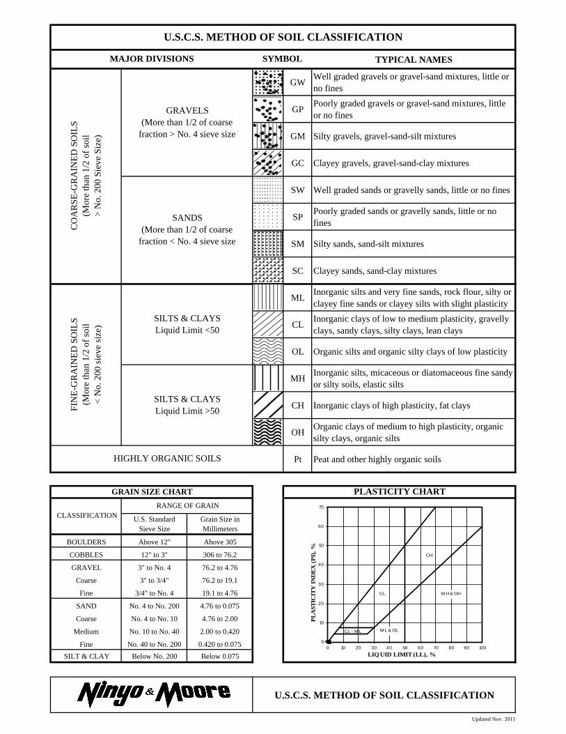
Classification Soils were visually and texturally classified in accordance with the Unified Soil Classification System (USCS) in general accordance with ASTM D 2488. Soil classifications are indicated on the logs of the exploratory borings in Appendix A.
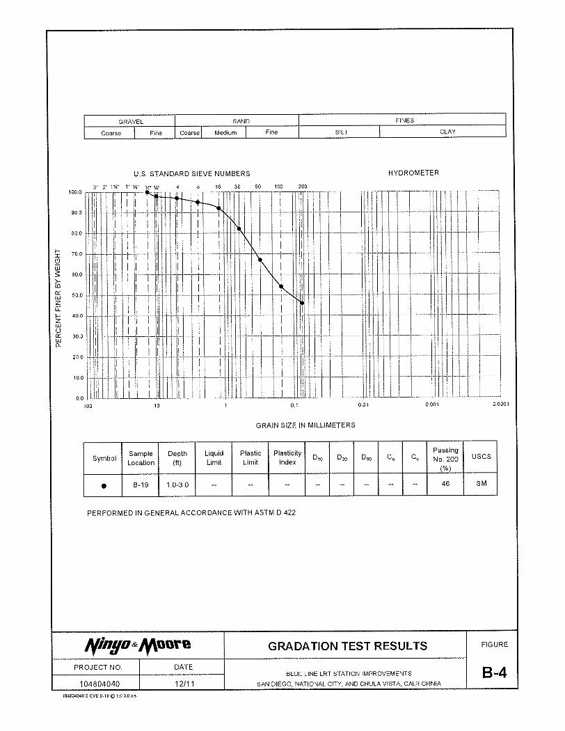
Gradation Analysis Gradation analysis tests were performed on selected representative soil samples in general accor-dance with ASTM D 422. The grain-size distribution curves are shown on Figures B-1 and B-2. Grain-size distribution curves from our previous evaluation are shown on Figures B-3 through B-6. These test results were utilized in evaluating the soil classifications in accordance with the USCS.
R-Value The resistance value, or R-value, for site soils was evaluated in general accordance with Califor-nia Test Method 301. Samples were prepared and evaluated for exudation pressure and expansion pressure. The equilibrium R-value is reported as the lesser or more conservative of the two calculated results. The test results are shown on Figure B-7.