geotechnical engineering report - v3co.com … · introduction geotechnical engineering report...
TRANSCRIPT
REPORT C OVER PAGE
Geotechnical Engineering Report Brewster Creek Project Oak
Bartlett, Illinois
April 10, 2018
Terracon Project No. MR185118R1
Prepared for:
V3 Companies, Ltd.
Woodridge, Illinois
Prepared by:
Terracon Consultants, Inc.
Naperville, Illinois.

Terracon Consultants, Inc. 135 Ambassador Drive Napervi l le, I l l inois 60540
P (630) 717 4263 F (630) 357 9489 terracon.com
REPORT C OVER LETTER TO SIGN
April 10, 2018
V3 Companies, Ltd.
7325 Janes Avenue, Suite 100
Woodridge, Illinois 60517
Attn: Mr. Keith Butkus
Re: Geotechnical Engineering Report
Brewster Creek Project Oak
southwest corner of North Bartlett Road and Naperville Road
Bartlett, Illinois
Terracon Project No. MR185118R1
Dear Mr. Butkus:
We have completed the Geotechnical Engineering services for the above referenced project. This
study was performed in general accordance with Terracon Proposal No. PMR185118 dated
March 20, 2018. This report presents the findings of the subsurface exploration and provides
geotechnical recommendations concerning earthwork and the design and construction of
foundations and floor slabs for the proposed project.
We appreciate the opportunity to be of service to you on this project. If you have any questions
concerning this report, or if we may be of further service, please contact us.
Sincerely,
Terracon Consultants, Inc.
Nathan J. Liggett, P.E. Paul A. Tarvin, P.E.
Project Manager Regional Geotechnical Manager

Responsive ■ Resourceful ■ Reliable
REPORT TOPICS
REPORT TOPICS
INTRODUCTION ............................................................................................................. 1 SITE CONDITIONS ......................................................................................................... 1
PROJECT DESCRIPTION .............................................................................................. 2 GEOTECHNICAL CHARACTERIZATION ...................................................................... 3 GEOTECHNICAL OVERVIEW ....................................................................................... 4 EARTHWORK ................................................................................................................ 5 SHALLOW FOUNDATIONS ......................................................................................... 10
FLOOR SLABS ............................................................................................................ 11 LATERAL EARTH PRESSURES ................................................................................. 13 SEISMIC CONSIDERATIONS ...................................................................................... 15
PAVEMENTS ................................................................................................................ 15 GENERAL COMMENTS ............................................................................................... 19
ATTACHMENTS
EXPLORATION AND TESTING PROCEDURES
SITE LOCATION AND EXPLORATION PLANS
EXPLORATION RESULTS (Current and Historical Boring Logs)
SUPPORTING INFORMATION (General Notes and Unified Soil Classification System)
Responsive ■ Resourceful ■ Reliable 1
INTRODUCTION
Geotechnical Engineering Report
Brewster Creek Project Oak
Southwest Corner of North Bartlett Road and Naperville Road
Bartlett, Illinois Terracon Project No. MR185118R1
April 10, 2018
INTRODUCTION
This report presents the results of our subsurface exploration and geotechnical engineering
services performed for the proposed development to be located at the southwest corner of North
Bartlett Road and Naperville Road in Bartlett, Illinois. The purpose of these services is to provide
information and geotechnical engineering recommendations relative to:
■ Subsurface soil conditions ■ Foundation design and construction
■ Groundwater conditions ■ Floor slab design and construction
■ Site preparation and earthwork ■ Seismic site classification per IBC
■ Dewatering considerations ■ Lateral earth pressures
■ Excavation considerations ■ Pavement design and construction
The current geotechnical engineering scope of services for this project included the advancement
of nine (9) soil borings to depths ranging from approximately 20 to 30 feet below existing site
grades. We also incorporated previous soil boring information completed by Terracon on the site.
Maps showing the site and boring locations are shown in the Site Location and Exploration
Plan sections, respectively. The results of the laboratory testing performed on soil samples
obtained from the site during the field exploration are included on the boring logs in the
Exploration Results section of this report.
SITE CONDITIONS
The following description of site conditions is derived from our site visit in association with the
field exploration and our review of publicly available geologic and topographic maps.

Geotechnical Engineering Report
Brewster Creek Project Oak ■ Bartlett, Illinois
April 10, 2018 ■ Terracon Project No. MR185118R1
Responsive ■ Resourceful ■ Reliable 2
Item Description
Parcel Information
The project is located along Spitzer Road, near the southwest corner of North
Bartlett Road and Naperville Road in Bartlett, Illinois. The total area of the site
is about 31.4 acres.
See Site Location
Existing
Improvements
The site was formerly used as a sand and gravel quarry, and has since been
filled.
Current Ground
Cover Lightly to moderately vegetated.
Existing Topography
(from a site topographic
map from V3)
There is a large fill pile located on the eastern portion of the site that extends
up to elevation 806 feet. The site grades are lower on the western half of the
site, and generally decline from south (794 feet) to north (773 feet), with about
18 feet of elevation difference within the proposed building footprint.
PROJECT DESCRIPTION
Our final understanding of the project conditions is as follows:
Item Description
Information Provided Based on a meeting with V3 and subsequent email correspondence from Mr. Keith Butkus. .
Project Description The project will consist of the construction of a precast concrete building.
Proposed Structure
The project includes a single-story building with a footprint of about 560,000 square feet (including room for future expansion). The building will be of typical slab-on-grade (non-basement) construction with a finished floor elevation of 791.5 feet. The pavements surrounding the proposed structure will have proposed surface elevations of 787.5 feet to allow for raised truck docks.
Building Construction The structure will most likely be steel framed with precast concrete panel walls.
Maximum Loads (provided by V3)
■ Columns: 150 kips ■ Walls: 4 kips per linear foot (klf) ■ Slabs: 500 pounds per square foot (psf)
Grading/Slopes
Up to 13 feet of cut and 17 feet of fill will be required to develop final grade.
Final slope angles of as steep as 3H:1V (Horizontal: Vertical) are expected.
Below Grade Structures None planned.
Free-Standing Retaining Walls
None planned.

Geotechnical Engineering Report
Brewster Creek Project Oak ■ Bartlett, Illinois
April 10, 2018 ■ Terracon Project No. MR185118R1
Responsive ■ Resourceful ■ Reliable 3
Item Description
Pavements
Paved driveway and parking will be constructed on the parcel.
We assume both rigid (concrete) and flexible (asphalt) pavement sections should be considered. Please confirm this assumption.
Anticipated traffic is as follows:
■ Autos/light trucks: 200 vehicles per day
■ Light delivery and trash collection vehicles: 10 vehicles per week
■ Tractor-trailer trucks: 500 vehicles per week
The pavement design period is 20 years.
GEOTECHNICAL CHARACTERIZATION
Subsurface Profile
We have developed a general characterization of the subsurface soil and groundwater conditions
based upon our review of the current and historical data and our understanding of the geologic
setting and planned construction. The following table provides our geotechnical characterization.
The geotechnical characterization forms the basis of our geotechnical calculations and evaluation
of site preparation, foundation options and pavement options. As noted in General Comments,
the characterization is based upon widely spaced exploration points across the site, and variations
are likely.
Stratum Approximate Elevation to
Bottom of Stratum Material Description Consistency/Density
1 Elev. 761 to 790 feet
FILL: typically consisting of lean to
silty clay, with varying amounts of
sand and gravel
N/A
2
Undetermined: Borings
terminated within this
stratum between Elev. 743
to 778 feet
Native soils consisting of lean clay
(CL) Stiff to very stiff
Native soils consisting of sand and
sand with gravel (SP)
Medium-dense to
dense
Conditions encountered at each boring location are indicated on the individual boring logs shown
in the Exploration Results section and are attached to this report. Stratification boundaries on
the boring logs represent the approximate location of changes in native soil types; in situ, the
transition between materials may be gradual.

Geotechnical Engineering Report
Brewster Creek Project Oak ■ Bartlett, Illinois
April 10, 2018 ■ Terracon Project No. MR185118R1
Responsive ■ Resourceful ■ Reliable 4
Groundwater Conditions
The boreholes were observed while drilling and after completion for the presence and level of
groundwater. The water levels observed in the boreholes can be found on the boring logs in
Exploration Results, and are summarized below.
Boring Number 1
Approximate Elevation of
Groundwater while Drilling
(feet)
Approximate Elevation of
Groundwater after Drilling
(feet)
B-4 757 feet None observed
B-6 764 feet None observed
B-2017 766 feet 765 feet
B-2018 764 feet None observed
B-2019 763 feet None observed
B-2020 768 feet 765 feet
B-2021 770.5 feet 765 feet
B-2023 761.5 feet None observed
B-2032 760.5 feet 756.5 feet
B-2034 757.5 feet None observed
1. Includes historical Terracon borings
Groundwater was not observed in the remaining borings while drilling, or for the short duration the
borings could remain open. However, this does not necessarily mean the borings terminated above
groundwater, or the water levels summarized above are stable groundwater levels. Due to the low
permeability of the soils encountered in the borings, a relatively long period may be necessary for a
groundwater level to develop and stabilize in a borehole. Long term observations in piezometers or
observation wells sealed from the influence of surface water are often required to define groundwater
levels in materials of this type.
Groundwater level fluctuations occur due to seasonal variations in the amount of rainfall, runoff
and other factors not evident at the time the borings were performed. Therefore, groundwater
levels during construction or at other times in the life of the structure may be higher or lower than
the levels indicated on the boring logs. The possibility of groundwater level fluctuations should be
considered when developing the design and construction plans for the project.
GEOTECHNICAL OVERVIEW
It is understood that the Client would like to support the proposed structure and pavements on a
partially over-excavated pad. As noted in Geotechnical Characterization, the borings

Geotechnical Engineering Report
Brewster Creek Project Oak ■ Bartlett, Illinois
April 10, 2018 ■ Terracon Project No. MR185118R1
Responsive ■ Resourceful ■ Reliable 5
encountered existing fill to elevations ranging from 761 feet to 790 feet. The fill may have been
placed in a controlled manner, but we have no records to indicate the degree of control. In
addition, certain portions of the fill had elevated moisture contents, suggesting they may be
somewhat compressible. Support of footings, floor slabs, and pavements above existing fill soils
is discussed in this report. However, even with the recommended construction procedures, there
is an inherent risk for the owner that compressible fill or unsuitable material within or buried by
the fill will not be discovered. This risk of unforeseen conditions cannot be eliminated without
completely removing the existing fill, but can be reduced by following the recommendations
contained in this report. The following recommendations have been developed with the
understanding that the Owner is willing to assume this risk.
The existing site fill should be undercut to Elev. 778.5 feet within the footprint of the building pad
and extending 15 feet laterally. Once the existing fill soils are undercut to Elev. 778.5 feet, the
exposed subgrade should be compacted using a sheeps foot roller, followed by proofrolling the
subgrade using a heavily loaded tandem-axel truck with a gross weight of at least 20 tons. New
engineered fill conforming to the specifications provided within this report should be placed in lifts
and compacted as specified in the following sections up to the proposed pad surface elevation of
790.5.
The Shallow Foundations section addresses footing support of the proposed structure. It is our
opinion that the structure can be supported on typical spread footing foundations bearing within
the newly-placed engineered fill used to construct the building pad. Shallow foundations may be
proportioned for a net allowable bearing pressure of 3,000 psf. We estimate total settlements of
less than 1-inch.
The Floor Slabs section addresses slab-on-grade support of structures. The floor slabs can be
grade supported on newly-placed engineered fill that appears stable under proofrolling.
Rigid and flexible pavement system recommendations are provided in this report. The
Pavements section addresses design and construction considerations for the proposed
pavement systems.
The General Comments section provides an understanding of the report limitations.
EARTHWORK
Earthwork will include clearing and grubbing, excavation and removal of a portion of the existing
fill, and new engineered fill placement. The following sections provide recommendations for use
in the preparation of specifications for the work. Recommendations include critical quality criteria

Geotechnical Engineering Report
Brewster Creek Project Oak ■ Bartlett, Illinois
April 10, 2018 ■ Terracon Project No. MR185118R1
Responsive ■ Resourceful ■ Reliable 6
as necessary to render the site in the state considered in our geotechnical engineering evaluation
for foundations, floor slabs, and pavements.
Site Preparation and Fill Placement
It is understood that the Client would like to support the proposed structure and pavements on a
partially over-excavated pad. As noted in Geotechnical Characterization, the borings
encountered existing fill to elevations ranging from 761 feet to 790 feet. The fill may have been
placed in a controlled manner, but we have no records to indicate the degree of control. In
addition, certain portions of the fill had elevated moisture contents, suggesting that these
materials may be somewhat compressible. Support of footings, floor slabs, and pavements above
existing fill soils is discussed in this report. However, even with the recommended construction
procedures, there is an inherent risk for the owner that compressible fill or unsuitable material
within or buried by the fill will not be discovered. This risk of unforeseen conditions cannot be
eliminated without completely removing the existing fill, but can be reduced by following the
recommendations contained in this report. The recommendations provided in this report have
been developed with the understanding that the owner is willing to assume this risk.
Based on the results of the borings, we recommend the following mass grading approach to
construct the proposed building pad for use with typical spread footing foundations, slab-on-grade
floors, and pavements:
■ Remove existing fill soils within the proposed building footprint, and extending 15 feet
beyond the building footprint, to an elevation of 778.5. It will not be necessary to undercut
competent native soils to this elevation. Excessively soft or loose native soils, or buried
topsoil, however, should also be removed. This approach will result in at least 12 feet of
compacted engineered fill to be placed below the building footprint to provide a firm base
to support the foundations and floor slabs.
■ Once the existing fill soils are undercut to Elev. 778.5 feet, the exposed subgrade should
be compacted using a sheeps foot roller, followed by proofrolling the subgrade using a
heavily loaded, tandem-axel truck with a gross weight of at least 20 tons. Any unstable
areas identified during proofroll, or if unsuitable fill soils are exposed at the undercut
subgrade elevation of 778.5 feet, the unsuitable soils should be scarified and
recompacted, or replaced with crushed stone.
■ New engineered fill conforming to the specifications provided within this report should be
placed and compacted as specified in the following sections up to the proposed pad
surface elevation of 790.5.
Geotechnical Engineering Report
Brewster Creek Project Oak ■ Bartlett, Illinois
April 10, 2018 ■ Terracon Project No. MR185118R1
Responsive ■ Resourceful ■ Reliable 7
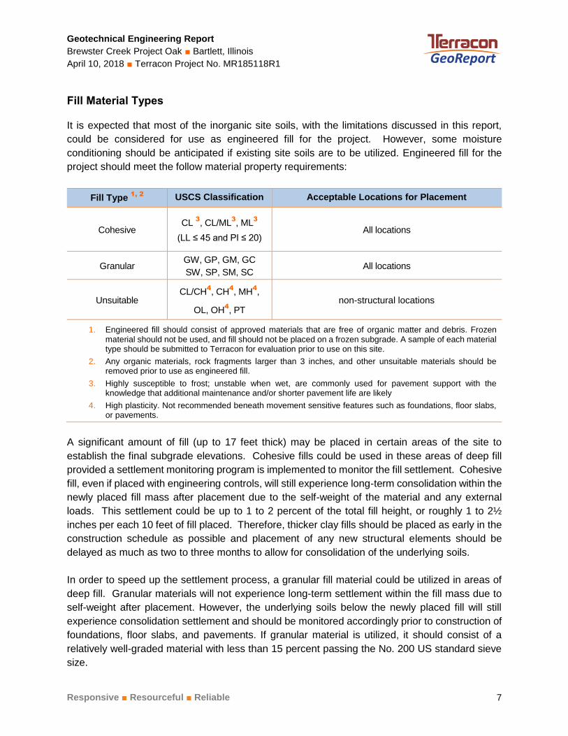
Fill Material Types
It is expected that most of the inorganic site soils, with the limitations discussed in this report,
could be considered for use as engineered fill for the project. However, some moisture
conditioning should be anticipated if existing site soils are to be utilized. Engineered fill for the
project should meet the follow material property requirements:
Fill Type 1, 2
USCS Classification Acceptable Locations for Placement
Cohesive CL
3
, CL/ML3
, ML3
(LL ≤ 45 and PI ≤ 20) All locations
Granular GW, GP, GM, GC
SW, SP, SM, SC All locations
Unsuitable CL/CH
4
, CH4
, MH4
,
OL, OH4
, PT non-structural locations
1. Engineered fill should consist of approved materials that are free of organic matter and debris. Frozen material should not be used, and fill should not be placed on a frozen subgrade. A sample of each material type should be submitted to Terracon for evaluation prior to use on this site.
2. Any organic materials, rock fragments larger than 3 inches, and other unsuitable materials should be removed prior to use as engineered fill.
3. Highly susceptible to frost; unstable when wet, are commonly used for pavement support with the knowledge that additional maintenance and/or shorter pavement life are likely
4. High plasticity. Not recommended beneath movement sensitive features such as foundations, floor slabs, or pavements.
A significant amount of fill (up to 17 feet thick) may be placed in certain areas of the site to
establish the final subgrade elevations. Cohesive fills could be used in these areas of deep fill
provided a settlement monitoring program is implemented to monitor the fill settlement. Cohesive
fill, even if placed with engineering controls, will still experience long-term consolidation within the
newly placed fill mass after placement due to the self-weight of the material and any external
loads. This settlement could be up to 1 to 2 percent of the total fill height, or roughly 1 to 2½
inches per each 10 feet of fill placed. Therefore, thicker clay fills should be placed as early in the
construction schedule as possible and placement of any new structural elements should be
delayed as much as two to three months to allow for consolidation of the underlying soils.
In order to speed up the settlement process, a granular fill material could be utilized in areas of
deep fill. Granular materials will not experience long-term settlement within the fill mass due to
self-weight after placement. However, the underlying soils below the newly placed fill will still
experience consolidation settlement and should be monitored accordingly prior to construction of
foundations, floor slabs, and pavements. If granular material is utilized, it should consist of a
relatively well-graded material with less than 15 percent passing the No. 200 US standard sieve
size.

Geotechnical Engineering Report
Brewster Creek Project Oak ■ Bartlett, Illinois
April 10, 2018 ■ Terracon Project No. MR185118R1
Responsive ■ Resourceful ■ Reliable 8
Fill Compaction Requirements
Engineered fill should meet the following compaction requirements.
Item Description
Maximum fill lift thickness
■ 9 inches or less in loose thickness when heavy, self-propelled
compaction equipment is used
■ 4 to 6 inches in loose thickness when hand-guided equipment
(i.e. jumping jack or plate compactor) is used
Minimum compaction
requirements 1, 2
■ 95% of the modified Proctor maximum dry density below the
building footpring; the compaction effort should extend laterally
beyond the foundations at least 8 inches for every foot of fill
placed.
■ 92% of the modified Proctor maximum dry density below the
pavement subgrade
Moisture content range 3
■ within 2% below to 3% above the modified Proctor optimum
moisture content at the time of placement and compaction for
cohesive soils
■ granular materials should be compacted within workable
moisture levels
1. We recommend that engineered fill be tested for moisture content and compaction during placement. Should the results of the in-place density tests indicate the specified moisture or compaction limits have not been met, the area represented by the test should be reworked and retested as required until the specified moisture and compaction requirements are achieved.
2. If the granular material is a coarse sand, crushed limestone, or gravel, is of a uniform size, or has a low fines content, compaction comparison to relative density (ASTM D 4253 and D 4254) may be more appropriate. In this case, granular materials should be compacted to at least 60% and 65% of the material’s maximum relative density for the 92% and 95% modified Proctor recommendations, respectively.
3. Specifically, moisture levels should be maintained to achieved compaction without bulking during placement or pumping when proofrolled.
Settlement Monitoring
If possible, the placement of fill to raise grades should be completed as early in the construction
schedule as possible to allow the underlying fill and native soils to consolidate under the additional
overburden pressure. Additionally, construction of pavements and any building foundations or
slabs over new fill should be delayed at least 4 to 6 weeks following completion of the fill
placement to allow for this consolidation. The significant thickness of fill that will be placed in
some areas (up to 17 feet) will cause consolidation of these soils.
To confirm the magnitude and time rate of settlement estimates provided above, we recommend
that a settlement monitoring program be implemented at the time of fill placement. Readings
should be made at least twice weekly and provided to the geotechnical engineer for review and
interpretation. The results will be used to make a final determination as to when construction of

Geotechnical Engineering Report
Brewster Creek Project Oak ■ Bartlett, Illinois
April 10, 2018 ■ Terracon Project No. MR185118R1
Responsive ■ Resourceful ■ Reliable 9
foundations, pavements and slabs over new fill can be completed. Terracon can be retained to
provide these services if needed.
Grading and Drainage
During construction, grades should be developed to direct surface water flow away from or around
the site. Exposed subgrades should be sloped to provide positive drainage so that saturation of
subgrades is avoided. Surface water should not be permitted to accumulate on the site.
Final grades should slope away from the structure to promote rapid surface drainage.
Accumulation of water adjacent to the structure could contribute to significant moisture increases
in the subgrade soils and subsequent softening/settlement. Roof drains should discharge into a
storm sewer or several feet away from the building.
Earthwork Construction Considerations
Terracon should be retained during the construction phase of the project to observe earthwork
and to perform necessary tests and observations during subgrade preparation, placement and
compaction of engineered fills, and backfilling of excavations.
Upon completion of filling and grading, care should be taken to maintain the moisture content of
the subgrade soils prior to construction of floor slabs. The site should also be graded to prevent
ponding of surface water on the prepared subgrades or in excavations. Any water that collects
over or adjacent to construction areas should be promptly removed. If the subgrade should
become frozen, desiccated, saturated, or disturbed, the affected material should be removed or
these materials should be scarified, moisture conditioned, and recompacted prior to floor slab
construction and observed by Terracon.
Care should be taken to avoid disturbance of prepared subgrade soils. The native clayey and fill
soils can be easily disturbed, especially by construction traffic. Construction traffic should not
operate directly on saturated or low strength soils. If the subgrade becomes saturated, desiccated,
or disturbed, the affected materials should either be scarified and compacted or be removed and
replaced as previously discussed. Subgrades should be observed and tested by Terracon prior
to construction.
Based on conditions encountered at the boring locations, excavations for the project are not
expected to encounter the long-term water table. However, some seepage may be encountered
if isolated granular seams containing perched free water is uncovered. If seepage is encountered,
the contractor is responsible for employing appropriate dewatering methods to control seepage
and facilitate construction. In our experience, dewatering of shallow excavations in clays or sands
above the water table can typically be accomplished with sump pits and pumps.

Geotechnical Engineering Report
Brewster Creek Project Oak ■ Bartlett, Illinois
April 10, 2018 ■ Terracon Project No. MR185118R1
Responsive ■ Resourceful ■ Reliable 10
As a minimum, excavations should be performed in accordance with OSHA 29 CFR, Part 1926,
Subpart P, “Excavations” and its appendices, as well as other applicable codes, and in
accordance with any applicable local, state, and federal safety regulations. The contractor should
be aware that slope height, slope inclination, and excavation depth should in no instance exceed
those specified by these safety regulations. The existing site fill soils are considered Type “C”
soils under the OSHA regulations. Maximum slope inclinations for Type “C” soils under the OSHA
regulations are 1.5H:1V.
Flatter slopes than those dictated by these regulations may be required depending upon the soil
conditions encountered and other external factors. These regulations are strictly enforced and if
they are not followed, the owner, the contractor, and/or earthwork and utility subcontractor could
be liable and subject to substantial penalties. Under no circumstances should the information
provided in this report be interpreted to mean that Terracon is responsible for construction site
safety or the contractor’s activities. Construction site safety is the sole responsibility of the
contractor who shall also be solely responsible for the means, methods, and sequencing of the
construction operations.
SHALLOW FOUNDATIONS
It is our opinion that the structure can be supported on typical spread footing foundations bearing
within the newly placed engineered soil fill following the over-excavation and replacement of the
existing site fill to Elev. 778.5 feet. We anticipate the new exterior foundations will bear at frost
depth.
Design Parameters
Item Description
Maximum Net Allowable Bearing
pressure 1
3,000 psf (footings bearing within newly placed engineered fill)
Minimum Foundation Dimensions Columns: 30 inches
Continuous: 18 inches
Ultimate Coefficient of Sliding Friction 2
0.35 (footings bearing on cohesive material)
0.45 (footings bearing on granular material)
Minimum Embedment below
Finished Grade 3
3.5 feet for heated structures
Estimated Total Settlement from
Structural Loads 4
Approximately 1 inch
Estimated Differential Settlement 4
About 2/3 of total settlement

Geotechnical Engineering Report
Brewster Creek Project Oak ■ Bartlett, Illinois
April 10, 2018 ■ Terracon Project No. MR185118R1
Responsive ■ Resourceful ■ Reliable 11
Item Description
1. The maximum net allowable bearing pressure is the pressure in excess of the minimum surrounding overburden pressure at the footing base elevation. An appropriate factor of safety has been applied. These bearing pressures can be increased by 1/3 for transient loads unless those loads have been factored to account for transient conditions.
2. Can be used to compute sliding resistance where foundations are placed on suitable soil/materials. Should be neglected for foundations subject to net uplift conditions.
3. Embedment necessary to minimize the effects of frost and/or seasonal water content variations. For sloping ground, maintain depth below the lowest adjacent exterior grade within 5 horizontal feet of the structure.
4. Foundation settlements will depend upon the variations within the subsurface soil profile, the structural loading conditions, the embedment depth of the footings, the thickness of engineered fill, and the quality of the earthwork operations and footing construction, frequent control joints should be provided for walls.
Uplift resistance of spread footings can be developed from the effective weight of the footing and
the overlying soils. The maximum allowable uplift capacity should be taken as a sum of the
effective weight of soil plus the dead weight of the foundation, divided by an appropriate factor of
safety. A maximum total unit weight of 120 pcf should be used for the backfill.
Foundation Construction Considerations
As noted in Earthwork, the footing excavations should be evaluated under the direction of the
Geotechnical Engineer. The base of all foundation excavations should be free of water and loose
soil, prior to placing concrete. Concrete should be placed soon after excavating to reduce bearing
soil disturbance. Care should be taken to prevent wetting or drying of the bearing materials during
construction. Excessively wet or dry material or any loose/disturbed material in the bottom of the
footing excavations should be removed/reconditioned before foundation concrete is placed.
It is understood that the footings will bear within the newly placed engineered fill building pad,
which will extend down to Elev. 778.5 feet at a minimum.
FLOOR SLABS
The floor slab for the structure can be supported on the newly placed engineered fill within the
building pad. We recommend that the thickness of the underslab leveling pad be a minimum of 4
inches and consist of free draining granular material.
Design parameters for floor slabs assume the requirements for Earthwork have been followed.
Specific attention should be given to positive drainage away from the structure and positive drainage
of the aggregate base beneath the floor slab
Geotechnical Engineering Report
Brewster Creek Project Oak ■ Bartlett, Illinois
April 10, 2018 ■ Terracon Project No. MR185118R1
Responsive ■ Resourceful ■ Reliable 12
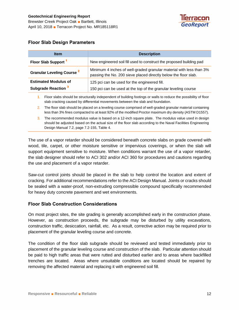
Floor Slab Design Parameters
Item Description
Floor Slab Support 1
New engineered soil fill used to construct the proposed building pad
Granular Leveling Course 2
Minimum 4 inches of well-graded granular material with less than 3%
passing the No. 200 sieve placed directly below the floor slab.
Estimated Modulus of
Subgrade Reaction 3
125 pci can be used for the engineered fill.
150 pci can be used at the top of the granular leveling course
1. Floor slabs should be structurally independent of building footings or walls to reduce the possibility of floor
slab cracking caused by differential movements between the slab and foundation.
2. The floor slab should be placed on a leveling course comprised of well-graded granular material containing
less than 3% fines compacted to at least 92% of the modified Proctor maximum dry density (ASTM D1557).
3. The recommended modulus value is based on a 12-inch square plate. The modulus value used in design
should be adjusted based on the actual size of the floor slab according to the Naval Facilities Engineering
Design Manual 7.2, page 7.2-155, Table 4.
The use of a vapor retarder should be considered beneath concrete slabs on grade covered with
wood, tile, carpet, or other moisture sensitive or impervious coverings, or when the slab will
support equipment sensitive to moisture. When conditions warrant the use of a vapor retarder,
the slab designer should refer to ACI 302 and/or ACI 360 for procedures and cautions regarding
the use and placement of a vapor retarder.
Saw-cut control joints should be placed in the slab to help control the location and extent of
cracking. For additional recommendations refer to the ACI Design Manual. Joints or cracks should
be sealed with a water-proof, non-extruding compressible compound specifically recommended
for heavy duty concrete pavement and wet environments.
Floor Slab Construction Considerations
On most project sites, the site grading is generally accomplished early in the construction phase.
However, as construction proceeds, the subgrade may be disturbed by utility excavations,
construction traffic, desiccation, rainfall, etc. As a result, corrective action may be required prior to
placement of the granular leveling course and concrete.
The condition of the floor slab subgrade should be reviewed and tested immediately prior to
placement of the granular leveling course and construction of the slab. Particular attention should
be paid to high traffic areas that were rutted and disturbed earlier and to areas where backfilled
trenches are located. Areas where unsuitable conditions are located should be repaired by
removing the affected material and replacing it with engineered soil fill.
Geotechnical Engineering Report
Brewster Creek Project Oak ■ Bartlett, Illinois
April 10, 2018 ■ Terracon Project No. MR185118R1
Responsive ■ Resourceful ■ Reliable 13
LATERAL EARTH PRESSURES
Design Parameters
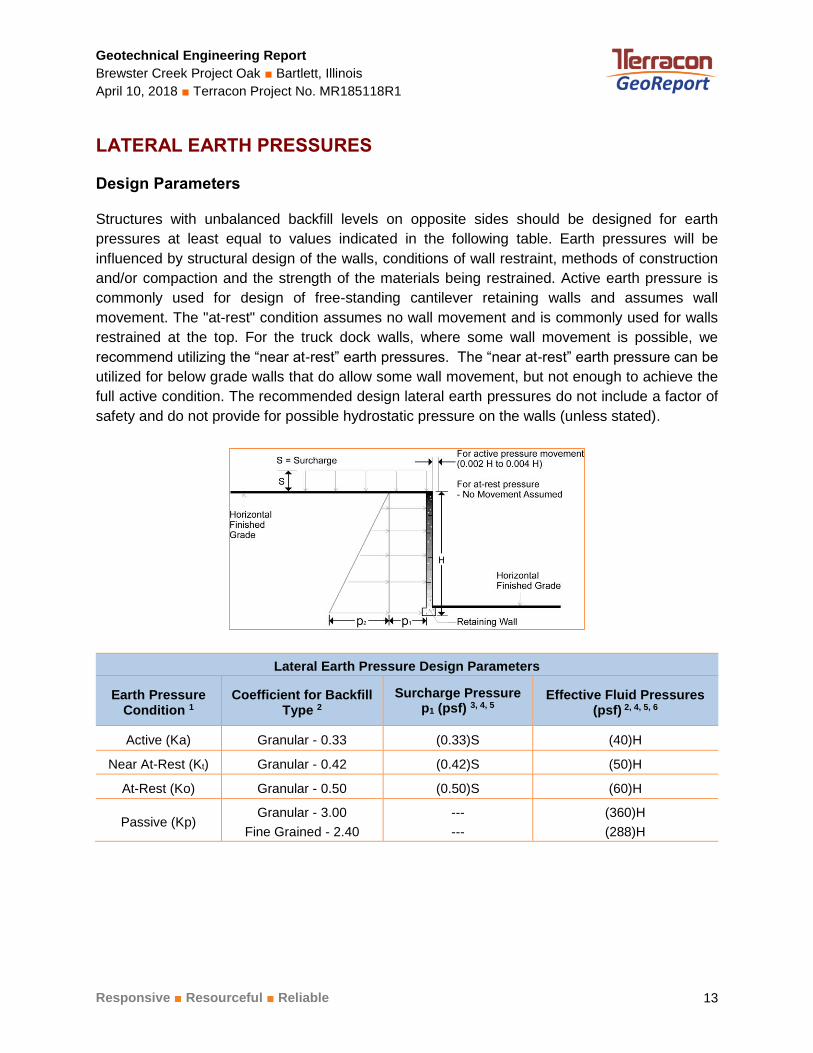
Structures with unbalanced backfill levels on opposite sides should be designed for earth
pressures at least equal to values indicated in the following table. Earth pressures will be
influenced by structural design of the walls, conditions of wall restraint, methods of construction
and/or compaction and the strength of the materials being restrained. Active earth pressure is
commonly used for design of free-standing cantilever retaining walls and assumes wall
movement. The "at-rest" condition assumes no wall movement and is commonly used for walls
restrained at the top. For the truck dock walls, where some wall movement is possible, we
recommend utilizing the “near at-rest” earth pressures. The “near at-rest” earth pressure can be
utilized for below grade walls that do allow some wall movement, but not enough to achieve the
full active condition. The recommended design lateral earth pressures do not include a factor of
safety and do not provide for possible hydrostatic pressure on the walls (unless stated).
Lateral Earth Pressure Design Parameters
Earth Pressure Condition 1
Coefficient for Backfill Type 2
Surcharge Pressure
p1 (psf) 3, 4, 5 Effective Fluid Pressures
(psf) 2, 4, 5, 6
Active (Ka) Granular - 0.33 (0.33)S (40)H
Near At-Rest (Kt) Granular - 0.42 (0.42)S (50)H
At-Rest (Ko) Granular - 0.50 (0.50)S (60)H
Passive (Kp) Granular - 3.00
Fine Grained - 2.40
---
---
(360)H
(288)H
Geotechnical Engineering Report
Brewster Creek Project Oak ■ Bartlett, Illinois
April 10, 2018 ■ Terracon Project No. MR185118R1
Responsive ■ Resourceful ■ Reliable 14
Lateral Earth Pressure Design Parameters
Earth Pressure Condition 1
Coefficient for Backfill Type 2
Surcharge Pressure
p1 (psf) 3, 4, 5 Effective Fluid Pressures
(psf) 2, 4, 5, 6
1. For active earth pressure, wall must rotate about base, with top lateral movements 0.002 H to 0.004 H, where H is wall height. For passive earth pressure, wall must move horizontally to mobilize resistance.
2. Uniform, horizontal backfill, compacted to at least 92 percent of the ASTM D 1556 maximum dry density, rendering a maximum unit weight of 120 pcf.
3. Uniform surcharge, where S is surcharge pressure.
4. Loading from heavy compaction equipment is not included.
5. No safety factor is included in these values. We recommend using a minimum factor of safety of 2 for calculations including passive earth pressures to account for the large strains required to mobilized the full passive resistance.
6. Assumes the walls are provided with sufficient drainage to prevent the build-up of hydrostatic pressures.
Backfill placed against structures should consist of granular soils. For the granular values to be
valid, the granular backfill must extend out and up from the base of the wall at an angle of at least
45 and 60 degrees from vertical for the active and passive cases, respectively.
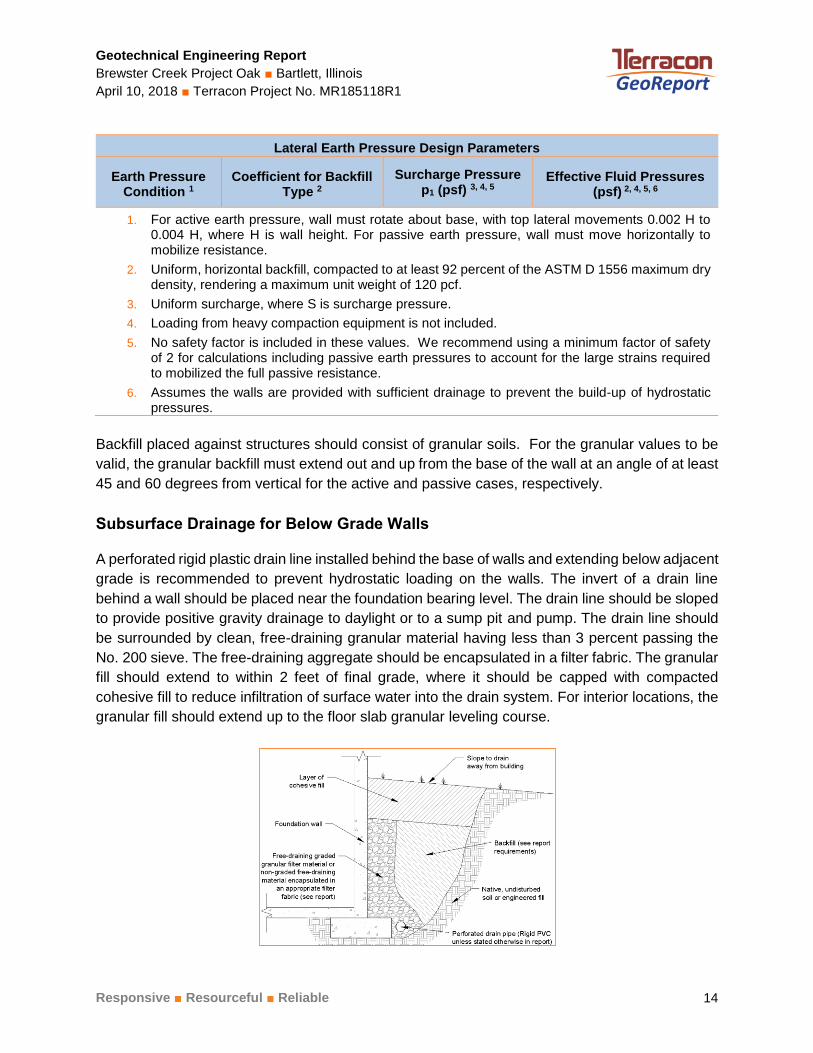
Subsurface Drainage for Below Grade Walls
A perforated rigid plastic drain line installed behind the base of walls and extending below adjacent
grade is recommended to prevent hydrostatic loading on the walls. The invert of a drain line
behind a wall should be placed near the foundation bearing level. The drain line should be sloped
to provide positive gravity drainage to daylight or to a sump pit and pump. The drain line should
be surrounded by clean, free-draining granular material having less than 3 percent passing the
No. 200 sieve. The free-draining aggregate should be encapsulated in a filter fabric. The granular
fill should extend to within 2 feet of final grade, where it should be capped with compacted
cohesive fill to reduce infiltration of surface water into the drain system. For interior locations, the
granular fill should extend up to the floor slab granular leveling course.

Geotechnical Engineering Report
Brewster Creek Project Oak ■ Bartlett, Illinois
April 10, 2018 ■ Terracon Project No. MR185118R1
Responsive ■ Resourceful ■ Reliable 15
As an alternative to free-draining granular fill, a pre-fabricated drainage structure may be used. A
pre-fabricated drainage structure is a plastic drainage core or mesh which is covered with filter
fabric to prevent soil intrusion, and is fastened to the wall prior to placing backfill.
SEISMIC CONSIDERATIONS
The seismic design requirements for buildings and other structures are based on Seismic Design
Category. Site Classification is required to determine the Seismic Design Category for a structure.
The Site Classification is based on the upper 100 feet of the site profile defined by a weighted
average value of either shear wave velocity, standard penetration resistance, or undrained shear
strength in accordance with Section 20.4 of ASCE 7-10.
Description Value
2015 International Building Code Site Classification (IBC) 1
D 2
Site Latitude 41.9877° N
Site Longitude 88.2267° W
SDS Spectral Acceleration for a Short Period 3
0.157g
SD1 Spectral Acceleration for a 1-Second Period 3
0.100g
1. Seismic site classification in general accordance with the 2015 International Building Code, which refers to
ASCE 7-10.
2. The 2015 International Building Code (IBC) uses a site profile extending to a depth of 100 feet for seismic
site classification. Borings at this site were extended to a maximum depth of 30 feet. The site properties below
the boring depth to 100 feet were estimated based on our experience and knowledge of geologic conditions
of the general area. Additional deeper borings or geophysical testing may be performed to confirm the
conditions below the current boring depth. 3. These values were obtained using online seismic design maps and tools provided by the USGS
(http://earthquake.usgs.gov/hazards/designmaps/).
PAVEMENTS
General Pavement Comments
Estimates of minimum pavement thicknesses are provided for the traffic conditions and pavement
life referenced in Project Description. A critical aspect of pavement performance is site
preparation. The minimum pavement thicknesses are based on the subgrades being prepared as
recommended in the Earthwork. The pavements may be supported above existing fill soils that
appear stable under proofrolling.
Geotechnical Engineering Report
Brewster Creek Project Oak ■ Bartlett, Illinois
April 10, 2018 ■ Terracon Project No. MR185118R1
Responsive ■ Resourceful ■ Reliable 16
There is often a time lapse between the end of grading operations and the commencement of
paving. Subgrades prepared early in the construction process can become disturbed by
construction traffic. Non-uniform subgrades often result in poor pavement performance and local
failures relatively soon after pavements are constructed. Depending on the paving equipment
used by the contractor, measures may be required to improve subgrade strength to greater depths
for support of heavily loaded trucks. Improvements should be made as recommended in
Earthwork.
Before paving, and where recommended by Terracon, pavement subgrades should be proofrolled
in the presence of a Terracon representative. Proofrolling of the subgrade should help locate soft,
yielding, or otherwise unsuitable soil at or just below the exposed subgrade level. Unsuitable
areas observed at this time should be improved by scarification and compaction or be removed
and replaced with engineered fill. Proofrolling should be accomplished with a fully loaded, tandem-
axle dump truck with a minimum gross weight of 25 tons or other equipment providing an
equivalent subgrade loading.
Pavement Design Parameters
Design of Asphaltic Concrete (AC) pavements are based on the procedures outlined in the
National Asphalt Pavement Association (NAPA) Information Series 109 (IS-109). Design of
Portland Cement Concrete (PCC) pavements are based upon American Concrete Institute (ACI)
330R-01; Guide for Design and Construction of Concrete Parking Lots.
A subgrade CBR of 5 was used for the AC pavement designs, and a modulus of subgrade reaction
of 125 pci was use for the PCC pavement designs. The values were empirically derived based
upon our experience with the described soil type subgrade soils and our understanding of the
quality of the subgrade as prescribed by the Site Preparation conditions as outlined in
Earthwork.
Pavement Section Thicknesses
All pavements should be designed for the types and volumes of traffic, subgrade and drainage
conditions that are anticipated. Terracon was not provided with anticipated traffic loading
information. The minimum thicknesses provided are based on 18-kip Equivalent Single Axle Load
Applications (ESAL18) over a 20-year design life, which are provided in the table below.

Geotechnical Engineering Report
Brewster Creek Project Oak ■ Bartlett, Illinois
April 10, 2018 ■ Terracon Project No. MR185118R1
Responsive ■ Resourceful ■ Reliable 17
Design Traffic
Pavement Type Location Design ESAL’s Values
Standard Duty 1
Rigid (Concrete) 75,000
Flexible (Bituminous) 50,000
Heavy Duty 2
Rigid (Concrete) 700,000
Flexible (Bituminous) 500,000
1. Recommended for parking areas subjected primarily to vehicular parking and drives with minimal truck and trailer traffic.
2. Recommended for areas subjected to heavy use or repeated truck and trailer traffic.
Based upon the design parameters listed above, we have developed recommended minimum
pavement sections for both bituminous (flexible) and Portland cement concrete (rigid), where the
subgrade appears firm under proof-rolling at the time of construction. The recommended
minimum pavement sections are provided in the following table. Greater pavement and/or base
course thicknesses may be required for greater expected traffic loads and volumes, or if poorer
subgrade conditions are encountered.
Asphaltic Concrete (AC)
Layer Thickness (inches)
Standard Duty Pavement Heavy Duty Pavement
AC Surface 2 2
AC Binder 2 2
Aggregate Base 1
8 12
1. The base course aggregate beneath the new pavement should conform to IDOT CA-6 or approved alternate gradation.
Portland Cement Concrete (PCC)
Layer Thickness (inches)
Standard Duty Pavement Heavy Duty Pavement
PCC 1
5 8
Aggregate Base 2
4 4
1. Portland cement concrete pavements are recommended for roadways and areas subjected to repeated truck traffic, truck turning areas, and trash container pads. Trash container pads should be large enough to support the container and the tipping axle of the trash collection vehicle.
2. The base course aggregate beneath the new pavement should conform to IDOT CA-6 or approved alternate gradation.
Geotechnical Engineering Report
Brewster Creek Project Oak ■ Bartlett, Illinois
April 10, 2018 ■ Terracon Project No. MR185118R1
Responsive ■ Resourceful ■ Reliable 18
Construction traffic on the pavements was not considered in developing the estimated minimum
pavement thicknesses. If the pavements will be subject to construction equipment/vehicles, the
pavement section should be revised to consider the additional loading.
The following comments should be considered for the indicated concrete pavement design
options.
■ Control joints should have a maximum spacing of about 30 times the thickness of the
concrete slab, as per American Concrete Institute (ACI) recommendations, and should be
placed in a roughly square pattern (where possible).
■ At construction joints, an adequately designed keyed construction joint or a butt end
construction joint is recommended. For a butt end construction joint, an adequate number
of deformed tie bars should be provided.
■ Tie bars are also recommended along the first longitudinal joint from the pavement edge
to keep the outside slab from separating from the pavement.
Pavement Drainage
Paved areas should be sloped to provide rapid drainage of surface water and to drain water away
from the pavement edges. Water should not be allowed to accumulate on or adjacent to the
pavement, since this could saturate and soften the subgrade soils and subsequently accelerate
pavement deterioration. Periodic maintenance of the pavements will be required. Cracks should
be sealed, and areas exhibiting distress should be repaired promptly to help prevent further
deterioration. Even with periodic maintenance, some movement and related cracking may still
occur and repairs may be required.
We recommend pavement subgrades be crowned at least 2 percent, to promote the flow of water
from the aggregate base towards subdrains, edge drains, or a suitable daylight or sewage inlet.
The pavement surfacing and adjacent sidewalks should be sloped to provide rapid drainage of
surface water. Water should not be allowed to pond on or adjacent to these grade-supported
slabs, since this could saturate the subgrade and contribute to premature pavement or slab
deterioration.
Pavement Maintenance
The pavement sections represent minimum recommended thicknesses and, as such, periodic
maintenance should be anticipated. Therefore, preventive maintenance should be planned and
provided for through an on-going pavement management program. Maintenance activities are
intended to slow the rate of pavement deterioration and to preserve the pavement investment.
Maintenance consists of both localized maintenance (e.g. crack and joint sealing and patching)
and global maintenance (e.g. surface sealing). Preventive maintenance is usually the priority
Geotechnical Engineering Report
Brewster Creek Project Oak ■ Bartlett, Illinois
April 10, 2018 ■ Terracon Project No. MR185118R1
Responsive ■ Resourceful ■ Reliable 19
when implementing a pavement maintenance program. Additional engineering observation is
recommended to determine the type and extent of a cost-effective program. Even with periodic
maintenance, some movements and related cracking may still occur and repairs may be required.
Pavement performance is affected by its surroundings. In addition to providing preventive
maintenance, the civil engineer should consider the following recommendations in the design and
layout of pavements:
■ Final grade adjacent to paved areas should slope down from the edges at a minimum 2%.
■ Subgrade and pavement surfaces should have a minimum 2% slope to promote proper
surface drainage.
■ Install below pavement drainage systems surrounding areas anticipated for frequent
wetting.
■ Install joint sealant and seal cracks immediately.
■ Seal all landscaped areas in or adjacent to pavements to reduce moisture migration to
subgrade soils.
■ Place compacted, low permeability backfill against the exterior side of curb and gutter.
■ Place curb, gutter and/or sidewalk directly on clay subgrade soils rather than on unbound
granular base course materials.
GENERAL COMMENTS
As the project progresses, we address assumptions by incorporating information provided by the
design team, if any. Revised project information that reflects actual conditions important to our
services is reflected in the final report. The design team should collaborate with Terracon to
confirm these assumptions and to prepare the final design plans and specifications. This
facilitates the incorporation of our opinions related to implementation of our geotechnical
recommendations. Any information conveyed prior to the final report is for informational purposes
only and should not be considered or used for decision-making purposes.
Our analysis and opinions are based upon our understanding of the project, the geotechnical
conditions in the area, and the data obtained from our site exploration. Natural variations will occur
between exploration point locations or due to the modifying effects of construction or weather.
The nature and extent of such variations may not become evident until during or after construction.
Terracon should be retained as the Geotechnical Engineer, where noted in the final report, to
provide observation and testing services during pertinent construction phases. If variations
appear, we can provide further evaluation and supplemental recommendations. If variations are
noted in the absence of our observation and testing services on-site, we should be immediately
notified so that we can provide evaluation and supplemental recommendations.

Geotechnical Engineering Report
Brewster Creek Project Oak ■ Bartlett, Illinois
April 10, 2018 ■ Terracon Project No. MR185118R1
Responsive ■ Resourceful ■ Reliable 20
Support of foundations, floor slabs and pavements on/above existing fill is discussed in this report.
Even with the construction observation/testing recommended in this report, a risk remains for the
owner that unsuitable materials within or buried by the fill will not be discovered. This may result
in larger than normal settlement and damage to foundations, floor slabs and pavements supported
above existing fill, requiring additional maintenance. This risk cannot be eliminated without
removing the existing fill from below the foundation, floor slab and pavement areas, but can be
reduced by thorough observation and testing as discussed herein.
Our scope of services does not include either specifically or by implication any environmental or
biological (e.g., mold, fungi, bacteria) assessment of the site or identification or prevention of
pollutants, hazardous materials or conditions. If the owner is concerned about the potential for
such contamination or pollution, other studies should be undertaken.
Our services and any correspondence or collaboration through this system are intended for the
sole benefit and exclusive use of our client for specific application to the project discussed and
are accomplished in accordance with generally accepted geotechnical engineering practices with
no third party beneficiaries intended. Any third party access to services or correspondence is
solely for information purposes to support the services provided by Terracon to our client.
Reliance upon the services and any work product is limited to our client, and is not intended for
third parties. Any use or reliance of the provided information by third parties is done solely at their
own risk. No warranties, either express or implied, are intended or made.
Site characteristics as provided are for design purposes and not to estimate excavation cost. Any
use of our report in that regard is done at the sole risk of the excavating cost estimator as there
may be variations on the site that are not apparent in the data that could significantly impact
excavation cost. Any parties charged with estimating excavation costs should seek their own site
characterization for specific purposes to obtain the specific level of detail necessary for costing.
Site safety, and cost estimating including, excavation support, and dewatering
requirements/design are the responsibility of others. If changes in the nature, design, or location
of the project are planned, our conclusions and recommendations shall not be considered valid
unless we review the changes and either verify or modify our conclusions in writing.

ATTACHM ENTS
ATTACHMENTS

MISC APPENDIX 1
EXPLORATION AND TESTING PROCEDURES

Geotechnical Engineering Report
Brewster Creek Project Oak ■ Bartlett, Illinois
April 10, 2018 ■ Terracon Project No. MR185118R1
Responsive ■ Resourceful ■ Reliable
EXPLORATION AND TESTING PROCEDURES
Field Exploration
Number of Borings Boring Depth (feet) Planned Location
9 20 to 30 or auger refusal Planned building area
Terracon previously performed fifteen (15) soil borings at this site in 2008 and documented in
Terracon Report No. 11085026, dated March 21, 2008. The pertinent historical soil borings are
provided in this report and the approximate boring locations are shown on the attached
Exploration Plan.
Boring Layout and Elevations: The current soil borings were staked in the field by the Client.
Terracon was provided with the as-drilled coordinates and elevations.
Subsurface Exploration Procedures: We advanced the borings with a track-mounted rotary drill
rig using continuous flight, hollow-stem augers. Four samples were obtained in the upper 10 feet
of each boring and at intervals of 5 feet thereafter. In the split-barrel sampling procedure, a standard
2-inch outer diameter split-barrel sampling spoon is driven into the ground by a 140-pound automatic
hammer falling a distance of 30 inches. The number of blows required to advance the sampling
spoon the last 12 inches of a normal 18-inch penetration is recorded as the Standard Penetration
Test (SPT) resistance value. The SPT resistance values, also referred to as N-values, are indicated
on the boring logs at the test depths. We observed and recorded groundwater levels during drilling
and sampling. For safety purposes, all borings were backfilled with a mixture of auger cuttings
and bentonite chips after their completion.
The sampling depths, penetration distances, and other sampling information were recorded on the
field boring logs. The samples were placed in appropriate containers and taken to our soil laboratory
for testing and classification by a geotechnical engineer. Our exploration team prepared field boring
logs as part of the drilling operations. These field logs include visual classifications of the materials
encountered during drilling and our interpretation of the subsurface conditions between samples.
Final boring logs were prepared from the field logs. The final boring logs represent the
geotechnical engineer's interpretation of the field logs and include modifications based on
observations and tests of the samples in our laboratory.
Laboratory Testing
The project engineer reviewed the field data and assigned various laboratory tests to better
understand the engineering properties of the various soil strata as necessary for this project.
Procedural standards noted below are for reference to methodology in general. In some cases,
variations to methods are applied because of local practice or professional judgment. Standards

Geotechnical Engineering Report
Brewster Creek Project Oak ■ Bartlett, Illinois
April 10, 2018 ■ Terracon Project No. MR185118R1
Responsive ■ Resourceful ■ Reliable
noted below include reference to other, related standards. Such references are not necessarily
applicable to describe the specific test performed.
■ ASTM D2216 Standard Test Methods for Laboratory Determination of Water (Moisture)
Content of Soil and Rock by Mass
The laboratory testing program included examination of soil samples by a geotechnical engineer.
Based on the material’s texture and plasticity, we described and classified the soil samples in
accordance with the Unified Soil Classification System.

SITE LOC ATION AND EXPLOR ATION PLAN S
SITE LOCATION AND EXPLORATION PLANS
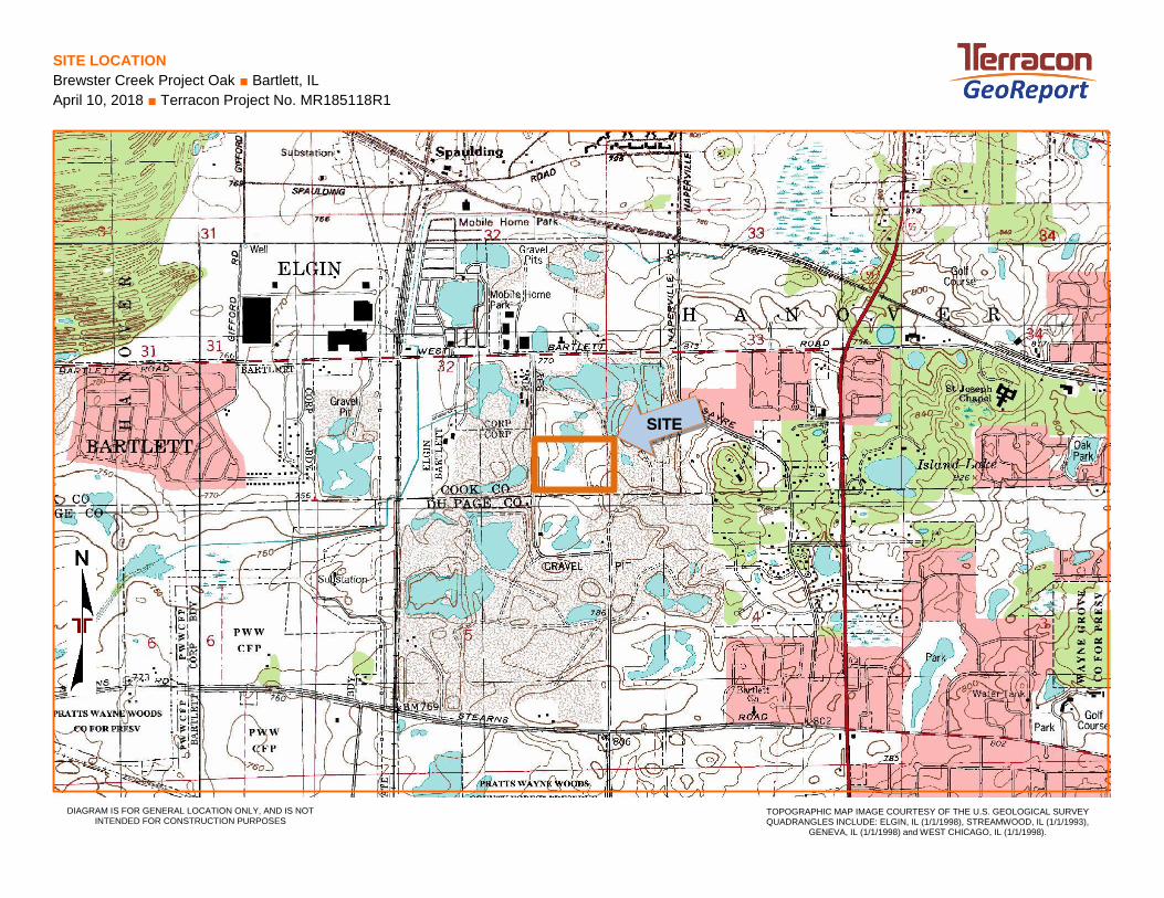
SITE LOCATION
Brewster Creek Project Oak ■ Bartlett, IL
April 10, 2018 ■ Terracon Project No. MR185118R1
DIAGRAM IS FOR GENERAL LOCATION ONLY, AND IS NOT INTENDED FOR CONSTRUCTION PURPOSES
TOPOGRAPHIC MAP IMAGE COURTESY OF THE U.S. GEOLOGICAL SURVEY QUADRANGLES INCLUDE: ELGIN, IL (1/1/1998), STREAMWOOD, IL (1/1/1993),
GENEVA, IL (1/1/1998) and WEST CHICAGO, IL (1/1/1998).
SITE
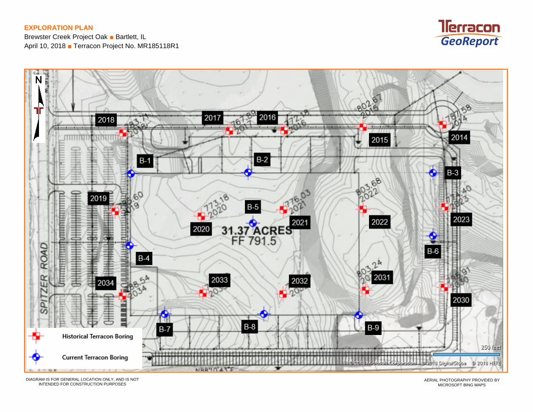
EXPLORATION PLAN
Brewster Creek Project Oak ■ Bartlett, IL
April 10, 2018 ■ Terracon Project No. MR185118R1
AERIAL PHOTOGRAPHY PROVIDED BY
MICROSOFT BING MAPS DIAGRAM IS FOR GENERAL LOCATION ONLY, AND IS NOT
INTENDED FOR CONSTRUCTION PURPOSES

EXPLOR ATION RESULTS
EXPLORATION RESULTS
21
23
24
23
23
7
775
768
763
3-3-5N=8
3-2-4N=6
6-11-14N=25
6-7-11N=18
2-1-1N=2
6-7-10N=17
18
18
18
18
18
13
1
2
3
4
5
6
8.0
15.0
20.0
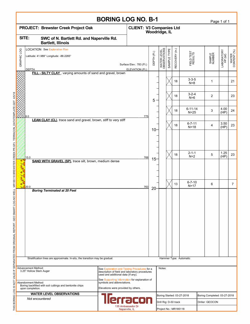
FILL - SILTY CLAY , varying amounts of sand and gravel, brown
LEAN CLAY (CL), trace sand and gravel, brown, stiff to very stiff
SAND WITH GRAVEL (SP), trace silt, brown, medium dense
Boring Terminated at 20 Feet
4.00(HP)
3.50(HP)
1.25(HP)
GR
AP
HIC
LO
G
Hammer Type: AutomaticStratification lines are approximate. In-situ, the transition may be gradual.
TH
IS B
OR
ING
LO
G IS
NO
T V
ALI
D IF
SE
PA
RA
TE
D F
RO
M O
RIG
INA
L R
EP
OR
T.
GE
O S
MA
RT
LO
G-N
O W
ELL
MR
1851
18 B
RE
WS
TE
R C
RE
EK
PR
.GP
J T
ER
RA
CO
N_D
AT
AT
EM
PLA
TE
.GD
T 4
/5/1
8
WA
TE
RC
ON
TE
NT
(%
)
ELEVATION (Ft.)
Surface Elev.: 783 (Ft.)
WA
TE
R L
EV
EL
OB
SE
RV
AT
ION
S
DE
PT
H (
Ft.)
5
10
15
20
SA
MP
LE T
YP
E
FIE
LD T
ES
TR
ES
ULT
S
RE
CO
VE
RY
(In
.)
SA
MP
LEN
UM
BE
R
DEPTH
LOCATION See Exploration Plan
Latitude: 41.989° Longitude: -88.2265°
Page 1 of 1
Advancement Method:3.25" Hollow Stem Auger
Abandonment Method:Boring backfilled with soil cuttings and bentonite chipsupon completion.
135 Ambassador DrNaperville, IL
Notes:
Project No.: MR185118
Drill Rig: D-50 track
BORING LOG NO. B-1V3 Companies LtdCLIENT:Woodridge, IL
Driller: GEOCON
Boring Completed: 03-27-2018
PROJECT: Brewster Creek Project Oak
Elevations were provided by others.
See Exploration and Testing Procedures for adescription of field and laboratory proceduresused and additional data (If any).
See Supporting Information for explanation ofsymbols and abbreviations.
SWC of N. Bartlett Rd. and Naperville Rd. Bartlett, IllinoisSITE:
Boring Started: 03-27-2018Not encountered
WATER LEVEL OBSERVATIONS
LAB
OR
AT
OR
YH
P (
tsf)
14
20
18
14
14
26
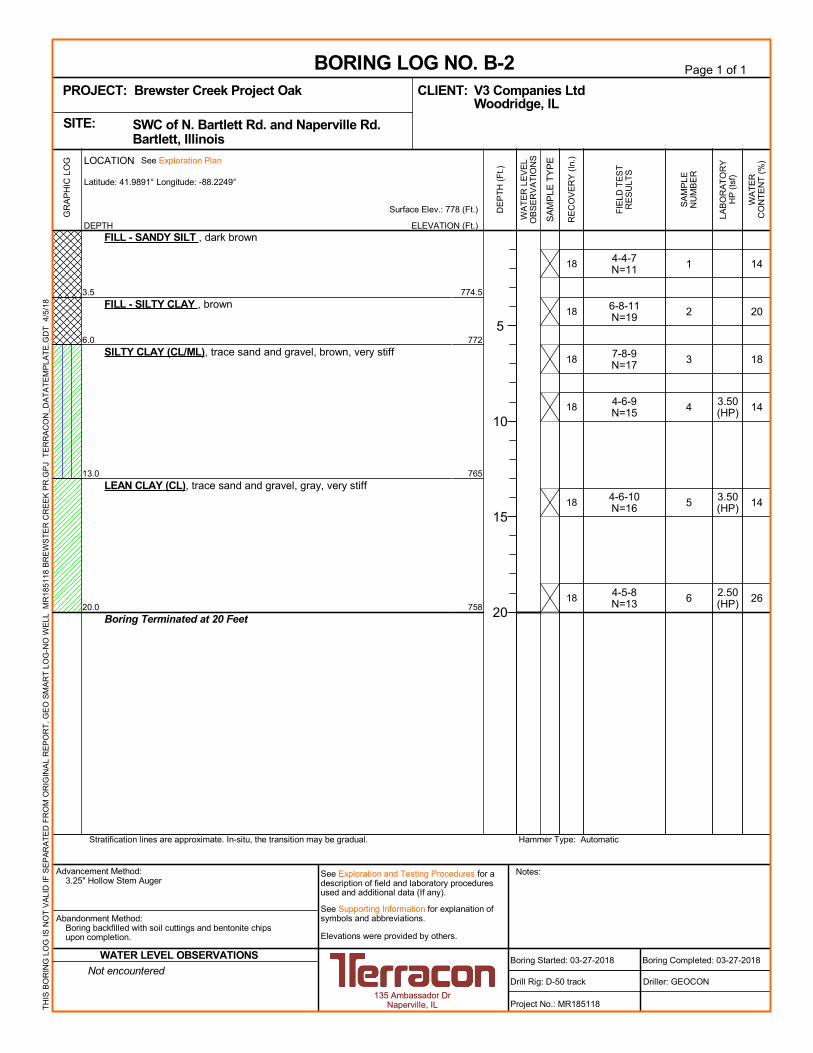
774.5
772
765
758
4-4-7N=11
6-8-11N=19
7-8-9N=17
4-6-9N=15
4-6-10N=16
4-5-8N=13
18
18
18
18
18
18
1
2
3
4
5
6
3.5
6.0
13.0
20.0
FILL - SANDY SILT , dark brown
FILL - SILTY CLAY , brown
SILTY CLAY (CL/ML), trace sand and gravel, brown, very stiff
LEAN CLAY (CL), trace sand and gravel, gray, very stiff
Boring Terminated at 20 Feet
3.50(HP)
3.50(HP)
2.50(HP)
GR
AP
HIC
LO
G
Hammer Type: AutomaticStratification lines are approximate. In-situ, the transition may be gradual.
TH
IS B
OR
ING
LO
G IS
NO
T V
ALI
D IF
SE
PA
RA
TE
D F
RO
M O
RIG
INA
L R
EP
OR
T.
GE
O S
MA
RT
LO
G-N
O W
ELL
MR
1851
18 B
RE
WS
TE
R C
RE
EK
PR
.GP
J T
ER
RA
CO
N_D
AT
AT
EM
PLA
TE
.GD
T 4
/5/1
8
WA
TE
RC
ON
TE
NT
(%
)
ELEVATION (Ft.)
Surface Elev.: 778 (Ft.)
WA
TE
R L
EV
EL
OB
SE
RV
AT
ION
S
DE
PT
H (
Ft.)
5
10
15
20
SA
MP
LE T
YP
E
FIE
LD T
ES
TR
ES
ULT
S
RE
CO
VE
RY
(In
.)
SA
MP
LEN
UM
BE
R
DEPTH
LOCATION See Exploration Plan
Latitude: 41.9891° Longitude: -88.2249°
Page 1 of 1
Advancement Method:3.25" Hollow Stem Auger
Abandonment Method:Boring backfilled with soil cuttings and bentonite chipsupon completion.
135 Ambassador DrNaperville, IL
Notes:
Project No.: MR185118
Drill Rig: D-50 track
BORING LOG NO. B-2V3 Companies LtdCLIENT:Woodridge, IL
Driller: GEOCON
Boring Completed: 03-27-2018
PROJECT: Brewster Creek Project Oak
Elevations were provided by others.
See Exploration and Testing Procedures for adescription of field and laboratory proceduresused and additional data (If any).
See Supporting Information for explanation ofsymbols and abbreviations.
SWC of N. Bartlett Rd. and Naperville Rd. Bartlett, IllinoisSITE:
Boring Started: 03-27-2018Not encountered
WATER LEVEL OBSERVATIONS
LAB
OR
AT
OR
YH
P (
tsf)

21
14
21
28
19
21
21
20
773
764763.5
743.5
5-11-5N=16
6-8-10N=18
7-7-5N=12
2-4-5N=9
5-8-11N=19
4-4-6N=10
2-4-6N=10
2-5-6N=11
12
12
10
8
12
14
16
16
1
2
3
4
5
6
7
8
0.5
9.510.0
30.0
FILL - GRAVEL SURFACE FILL - LEAN CLAY , varying amounts of sand and gravel, brown togray
ORIGINAL TOPSOIL, clayey, blackLEAN CLAY (CL), trace sand and gravel, gray, very stiff to hard
Boring Terminated at 30 Feet
2.00(HP)
3.00(HP)
3.00(HP)
dist.
5.00(HP)
2.50(HP)
2.75(HP)
2.50(HP)
GR
AP
HIC
LO
G
Hammer Type: AutomaticStratification lines are approximate. In-situ, the transition may be gradual.
TH
IS B
OR
ING
LO
G IS
NO
T V
ALI
D IF
SE
PA
RA
TE
D F
RO
M O
RIG
INA
L R
EP
OR
T.
GE
O S
MA
RT
LO
G-N
O W
ELL
MR
1851
18 B
RE
WS
TE
R C
RE
EK
PR
.GP
J T
ER
RA
CO
N_D
AT
AT
EM
PLA
TE
.GD
T 4
/5/1
8
WA
TE
RC
ON
TE
NT
(%
)
ELEVATION (Ft.)
Surface Elev.: 773.5 (Ft.)
WA
TE
R L
EV
EL
OB
SE
RV
AT
ION
S
DE
PT
H (
Ft.)
5
10
15
20
25
30
SA
MP
LE T
YP
E
FIE
LD T
ES
TR
ES
ULT
S
RE
CO
VE
RY
(In
.)
SA
MP
LEN
UM
BE
R
DEPTH
LOCATION See Exploration Plan
Latitude: 41.9891° Longitude: -88.2224°
Page 1 of 1
Advancement Method:3.25" Hollow Stem Auger
Abandonment Method:Boring backfilled with soil cuttings and bentonite chipsupon completion.
135 Ambassador DrNaperville, IL
Notes:
Project No.: MR185118
Drill Rig: D-50 track
BORING LOG NO. B-3V3 Companies LtdCLIENT:Woodridge, IL
Driller: GEOCON
Boring Completed: 03-28-2018
PROJECT: Brewster Creek Project Oak
Elevations were provided by others.
See Exploration and Testing Procedures for adescription of field and laboratory proceduresused and additional data (If any).
See Supporting Information for explanation ofsymbols and abbreviations.
SWC of N. Bartlett Rd. and Naperville Rd. Bartlett, IllinoisSITE:
Boring Started: 03-28-2018Not encountered
WATER LEVEL OBSERVATIONS
LAB
OR
AT
OR
YH
P (
tsf)
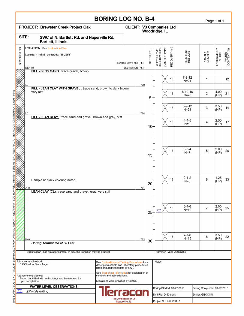
12
21
14
17
26
33
25
22
779
774
761
752
7-9-12N=21
8-10-16N=26
5-9-12N=21
4-4-5N=9
3-3-4N=7
2-1-2N=3
5-4-6N=10
7-7-8N=15
18
18
18
18
18
18
18
18
1
2
3
4
5
6
7
8
3.0
8.0
21.0
30.0
FILL - SILTY SAND , trace gravel, brown
FILL - LEAN CLAY WITH GRAVEL , trace sand, brown to dark brown,very stiff
FILL - LEAN CLAY , trace sand and gravel, brown and gray, stiff
Sample 6: black coloring noted.
LEAN CLAY (CL), trace sand and gravel, gray, very stiff
Boring Terminated at 30 Feet
4.00(HP)
3.50(HP)
2.50(HP)
2.00(HP)
1.25(HP)
2.00(HP)
3.50(HP)
GR
AP
HIC
LO
G
Hammer Type: AutomaticStratification lines are approximate. In-situ, the transition may be gradual.
TH
IS B
OR
ING
LO
G IS
NO
T V
ALI
D IF
SE
PA
RA
TE
D F
RO
M O
RIG
INA
L R
EP
OR
T.
GE
O S
MA
RT
LO
G-N
O W
ELL
MR
1851
18 B
RE
WS
TE
R C
RE
EK
PR
.GP
J T
ER
RA
CO
N_D
AT
AT
EM
PLA
TE
.GD
T 4
/5/1
8
WA
TE
RC
ON
TE
NT
(%
)
ELEVATION (Ft.)
Surface Elev.: 782 (Ft.)
WA
TE
R L
EV
EL
OB
SE
RV
AT
ION
S
DE
PT
H (
Ft.)
5
10
15
20
25
30
SA
MP
LE T
YP
E
FIE
LD T
ES
TR
ES
ULT
S
RE
CO
VE
RY
(In
.)
SA
MP
LEN
UM
BE
R
DEPTH
LOCATION See Exploration Plan
Latitude: 41.9883° Longitude: -88.2265°
Page 1 of 1
Advancement Method:3.25" Hollow Stem Auger
Abandonment Method:Boring backfilled with soil cuttings and bentonite chipsupon completion.
135 Ambassador DrNaperville, IL
Notes:
Project No.: MR185118
Drill Rig: D-50 track
BORING LOG NO. B-4V3 Companies LtdCLIENT:Woodridge, IL
Driller: GEOCON
Boring Completed: 03-27-2018
PROJECT: Brewster Creek Project Oak
Elevations were provided by others.
See Exploration and Testing Procedures for adescription of field and laboratory proceduresused and additional data (If any).
See Supporting Information for explanation ofsymbols and abbreviations.
SWC of N. Bartlett Rd. and Naperville Rd. Bartlett, IllinoisSITE:
Boring Started: 03-27-201825' while drilling
WATER LEVEL OBSERVATIONS
LAB
OR
AT
OR
YH
P (
tsf)

14
15
16
19
17
23
772.5
762.5
760.5
3-5-5N=10
3-6-5N=11
6-6-6N=12
4-5-6N=11
3-2-4N=6
2-2-3N=5
18
18
18
18
10
18
1
2
3
4
5
6
8.0
18.0
20.0
FILL - SILTY CLAY , trace sand and gravel, brown and gray
LEAN CLAY (CL), trace sand and gravel, brown, very stiff to hard
LEAN CLAY (CL), trace sand and gravel, brown, stiff
Boring Terminated at 20 Feet
3.00(HP)
4.00(HP)
3.50(HP)
4.50(HP)
2.50(HP)
1.25(HP)
GR
AP
HIC
LO
G
Hammer Type: AutomaticStratification lines are approximate. In-situ, the transition may be gradual.
TH
IS B
OR
ING
LO
G IS
NO
T V
ALI
D IF
SE
PA
RA
TE
D F
RO
M O
RIG
INA
L R
EP
OR
T.
GE
O S
MA
RT
LO
G-N
O W
ELL
MR
1851
18 B
RE
WS
TE
R C
RE
EK
PR
.GP
J T
ER
RA
CO
N_D
AT
AT
EM
PLA
TE
.GD
T 4
/5/1
8
WA
TE
RC
ON
TE
NT
(%
)
ELEVATION (Ft.)
Surface Elev.: 780.5 (Ft.)
WA
TE
R L
EV
EL
OB
SE
RV
AT
ION
S
DE
PT
H (
Ft.)
5
10
15
20
SA
MP
LE T
YP
E
FIE
LD T
ES
TR
ES
ULT
S
RE
CO
VE
RY
(In
.)
SA
MP
LEN
UM
BE
R
DEPTH
LOCATION See Exploration Plan
Latitude: 41.9885° Longitude: -88.2248°
Page 1 of 1
Advancement Method:3.25" Hollow Stem Auger
Abandonment Method:Boring backfilled with soil cuttings and bentonite chipsupon completion.
135 Ambassador DrNaperville, IL
Notes:
Project No.: MR185118
Drill Rig: D-50 track
BORING LOG NO. B-5V3 Companies LtdCLIENT:Woodridge, IL
Driller: GEOCON
Boring Completed: 03-27-2018
PROJECT: Brewster Creek Project Oak
Elevations were provided by others.
See Exploration and Testing Procedures for adescription of field and laboratory proceduresused and additional data (If any).
See Supporting Information for explanation ofsymbols and abbreviations.
SWC of N. Bartlett Rd. and Naperville Rd. Bartlett, IllinoisSITE:
Boring Started: 03-27-2018Not encountered
WATER LEVEL OBSERVATIONS
LAB
OR
AT
OR
YH
P (
tsf)

14
12
4
1
5
6
10
5
782.5
779
757
5-6-8N=14
6-7-7N=14
4-5-9N=14
13-27-30N=57
17-26-33N=59
28-29-31N=60
14-23-50/3"N=23+50/3"
15-18-13N=31
10
10
10
14
12
12
8
6
1
2
3
4
5
6
7
8
4.5
8.0
30.0
FILL - LEAN CLAY TO SANDY CLAY , trace gravel, brown
SAND (SP), trace gravel, brown, medium dense
SAND WITH GRAVEL (SP), trace silt, brown, dense
Boring Terminated at 30 Feet
2.75(HP)
1.50(HP)
GR
AP
HIC
LO
G
Hammer Type: AutomaticStratification lines are approximate. In-situ, the transition may be gradual.
TH
IS B
OR
ING
LO
G IS
NO
T V
ALI
D IF
SE
PA
RA
TE
D F
RO
M O
RIG
INA
L R
EP
OR
T.
GE
O S
MA
RT
LO
G-N
O W
ELL
MR
1851
18 B
RE
WS
TE
R C
RE
EK
PR
.GP
J T
ER
RA
CO
N_D
AT
AT
EM
PLA
TE
.GD
T 4
/5/1
8
WA
TE
RC
ON
TE
NT
(%
)
ELEVATION (Ft.)
Surface Elev.: 787 (Ft.)
WA
TE
R L
EV
EL
OB
SE
RV
AT
ION
S
DE
PT
H (
Ft.)
5
10
15
20
25
30
SA
MP
LE T
YP
E
FIE
LD T
ES
TR
ES
ULT
S
RE
CO
VE
RY
(In
.)
SA
MP
LEN
UM
BE
R
DEPTH
LOCATION See Exploration Plan
Latitude: 41.9884° Longitude: -88.2224°
Page 1 of 1
Advancement Method:3.25" Hollow Stem Auger
Abandonment Method:Boring backfilled with soil cuttings and bentonite chipsupon completion.
135 Ambassador DrNaperville, IL
Notes:
Project No.: MR185118
Drill Rig: D-50 track
BORING LOG NO. B-6V3 Companies LtdCLIENT:Woodridge, IL
Driller: GEOCON
Boring Completed: 03-28-2018
PROJECT: Brewster Creek Project Oak
Elevations were provided by others.
See Exploration and Testing Procedures for adescription of field and laboratory proceduresused and additional data (If any).
See Supporting Information for explanation ofsymbols and abbreviations.
SWC of N. Bartlett Rd. and Naperville Rd. Bartlett, IllinoisSITE:
Boring Started: 03-28-201823' while drilling
WATER LEVEL OBSERVATIONS
LAB
OR
AT
OR
YH
P (
tsf)
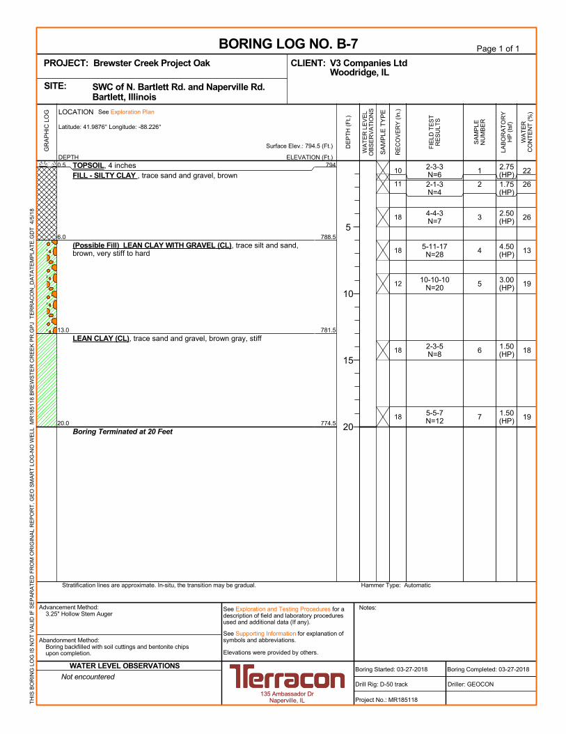
22
26
26
13
19
18
19
794
788.5
781.5
774.5
2-3-3N=62-1-3N=4
4-4-3N=7
5-11-17N=28
10-10-10N=20
2-3-5N=8
5-5-7N=12
10
11
18
18
12
18
18
1
2
3
4
5
6
7
0.5
6.0
13.0
20.0
TOPSOIL, 4 inchesFILL - SILTY CLAY , trace sand and gravel, brown
(Possible Fill) LEAN CLAY WITH GRAVEL (CL), trace silt and sand,brown, very stiff to hard
LEAN CLAY (CL), trace sand and gravel, brown gray, stiff
Boring Terminated at 20 Feet
2.75(HP)1.75(HP)
2.50(HP)
4.50(HP)
3.00(HP)
1.50(HP)
1.50(HP)
GR
AP
HIC
LO
G
Hammer Type: AutomaticStratification lines are approximate. In-situ, the transition may be gradual.
TH
IS B
OR
ING
LO
G IS
NO
T V
ALI
D IF
SE
PA
RA
TE
D F
RO
M O
RIG
INA
L R
EP
OR
T.
GE
O S
MA
RT
LO
G-N
O W
ELL
MR
1851
18 B
RE
WS
TE
R C
RE
EK
PR
.GP
J T
ER
RA
CO
N_D
AT
AT
EM
PLA
TE
.GD
T 4
/5/1
8
WA
TE
RC
ON
TE
NT
(%
)
ELEVATION (Ft.)
Surface Elev.: 794.5 (Ft.)
WA
TE
R L
EV
EL
OB
SE
RV
AT
ION
S
DE
PT
H (
Ft.)
5
10
15
20
SA
MP
LE T
YP
E
FIE
LD T
ES
TR
ES
ULT
S
RE
CO
VE
RY
(In
.)
SA
MP
LEN
UM
BE
R
DEPTH
LOCATION See Exploration Plan
Latitude: 41.9876° Longitude: -88.226°
Page 1 of 1
Advancement Method:3.25" Hollow Stem Auger
Abandonment Method:Boring backfilled with soil cuttings and bentonite chipsupon completion.
135 Ambassador DrNaperville, IL
Notes:
Project No.: MR185118
Drill Rig: D-50 track
BORING LOG NO. B-7V3 Companies LtdCLIENT:Woodridge, IL
Driller: GEOCON
Boring Completed: 03-27-2018
PROJECT: Brewster Creek Project Oak
Elevations were provided by others.
See Exploration and Testing Procedures for adescription of field and laboratory proceduresused and additional data (If any).
See Supporting Information for explanation ofsymbols and abbreviations.
SWC of N. Bartlett Rd. and Naperville Rd. Bartlett, IllinoisSITE:
Boring Started: 03-27-2018Not encountered
WATER LEVEL OBSERVATIONS
LAB
OR
AT
OR
YH
P (
tsf)
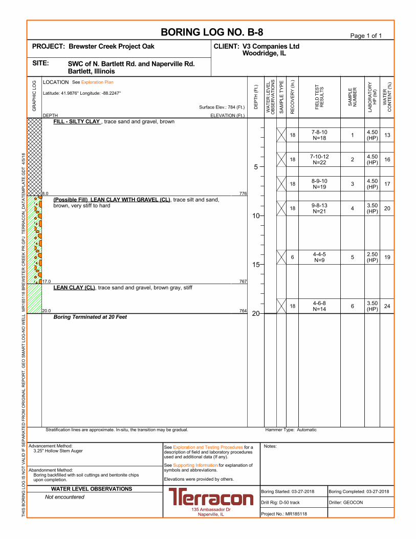
13
16
17
20
19
24
776
767
764
7-8-10N=18
7-10-12N=22
8-9-10N=19
9-8-13N=21
4-4-5N=9
4-6-8N=14
18
18
18
18
6
18
1
2
3
4
5
6
8.0
17.0
20.0
FILL - SILTY CLAY , trace sand and gravel, brown
(Possible Fill) LEAN CLAY WITH GRAVEL (CL), trace silt and sand,brown, very stiff to hard
LEAN CLAY (CL), trace sand and gravel, brown gray, stiff
Boring Terminated at 20 Feet
4.50(HP)
4.50(HP)
4.50(HP)
3.50(HP)
2.50(HP)
3.50(HP)
GR
AP
HIC
LO
G
Hammer Type: AutomaticStratification lines are approximate. In-situ, the transition may be gradual.
TH
IS B
OR
ING
LO
G IS
NO
T V
ALI
D IF
SE
PA
RA
TE
D F
RO
M O
RIG
INA
L R
EP
OR
T.
GE
O S
MA
RT
LO
G-N
O W
ELL
MR
1851
18 B
RE
WS
TE
R C
RE
EK
PR
.GP
J T
ER
RA
CO
N_D
AT
AT
EM
PLA
TE
.GD
T 4
/5/1
8
WA
TE
RC
ON
TE
NT
(%
)
ELEVATION (Ft.)
Surface Elev.: 784 (Ft.)
WA
TE
R L
EV
EL
OB
SE
RV
AT
ION
S
DE
PT
H (
Ft.)
5
10
15
20
SA
MP
LE T
YP
E
FIE
LD T
ES
TR
ES
ULT
S
RE
CO
VE
RY
(In
.)
SA
MP
LEN
UM
BE
R
DEPTH
LOCATION See Exploration Plan
Latitude: 41.9876° Longitude: -88.2247°
Page 1 of 1
Advancement Method:3.25" Hollow Stem Auger
Abandonment Method:Boring backfilled with soil cuttings and bentonite chipsupon completion.
135 Ambassador DrNaperville, IL
Notes:
Project No.: MR185118
Drill Rig: D-50 track
BORING LOG NO. B-8V3 Companies LtdCLIENT:Woodridge, IL
Driller: GEOCON
Boring Completed: 03-27-2018
PROJECT: Brewster Creek Project Oak
Elevations were provided by others.
See Exploration and Testing Procedures for adescription of field and laboratory proceduresused and additional data (If any).
See Supporting Information for explanation ofsymbols and abbreviations.
SWC of N. Bartlett Rd. and Naperville Rd. Bartlett, IllinoisSITE:
Boring Started: 03-27-2018Not encountered
WATER LEVEL OBSERVATIONS
LAB
OR
AT
OR
YH
P (
tsf)
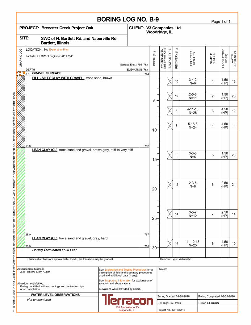
16
26
12
14
20
24
14
10
794
782
767
765
3-4-2N=6
2-5-6N=11
4-11-15N=26
5-16-8N=24
3-3-3N=6
2-3-5N=8
3-5-7N=12
11-12-13N=25
10
12
8
8
8
12
14
14
1
2
3
4
5
6
7
8
0.8
13.0
28.0
30.0
GRAVEL SURFACE
FILL - SILTY CLAY WITH GRAVEL , trace sand, brown
LEAN CLAY (CL), trace sand and gravel, brown gray, stiff to very stiff
LEAN CLAY (CL), trace sand and gravel, gray, hard
Boring Terminated at 30 Feet
1.50(HP)
1.50(HP)
4.50(HP)
4.50(HP)
1.50(HP)
2.50(HP)
2.50(HP)
4.50(HP)
GR
AP
HIC
LO
G
Hammer Type: AutomaticStratification lines are approximate. In-situ, the transition may be gradual.
TH
IS B
OR
ING
LO
G IS
NO
T V
ALI
D IF
SE
PA
RA
TE
D F
RO
M O
RIG
INA
L R
EP
OR
T.
GE
O S
MA
RT
LO
G-N
O W
ELL
MR
1851
18 B
RE
WS
TE
R C
RE
EK
PR
.GP
J T
ER
RA
CO
N_D
AT
AT
EM
PLA
TE
.GD
T 4
/5/1
8
WA
TE
RC
ON
TE
NT
(%
)
ELEVATION (Ft.)
Surface Elev.: 795 (Ft.)
WA
TE
R L
EV
EL
OB
SE
RV
AT
ION
S
DE
PT
H (
Ft.)
5
10
15
20
25
30
SA
MP
LE T
YP
E
FIE
LD T
ES
TR
ES
ULT
S
RE
CO
VE
RY
(In
.)
SA
MP
LEN
UM
BE
R
DEPTH
LOCATION See Exploration Plan
Latitude: 41.9876° Longitude: -88.2234°
Page 1 of 1
Advancement Method:3.25" Hollow Stem Auger
Abandonment Method:Boring backfilled with soil cuttings and bentonite chipsupon completion.
135 Ambassador DrNaperville, IL
Notes:
Project No.: MR185118
Drill Rig: D-50 track
BORING LOG NO. B-9V3 Companies LtdCLIENT:Woodridge, IL
Driller: GEOCON
Boring Completed: 03-28-2018
PROJECT: Brewster Creek Project Oak
Elevations were provided by others.
See Exploration and Testing Procedures for adescription of field and laboratory proceduresused and additional data (If any).
See Supporting Information for explanation ofsymbols and abbreviations.
SWC of N. Bartlett Rd. and Naperville Rd. Bartlett, IllinoisSITE:
Boring Started: 03-28-2018Not encountered
WATER LEVEL OBSERVATIONS
LAB
OR
AT
OR
YH
P (
tsf)

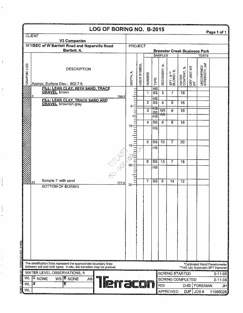


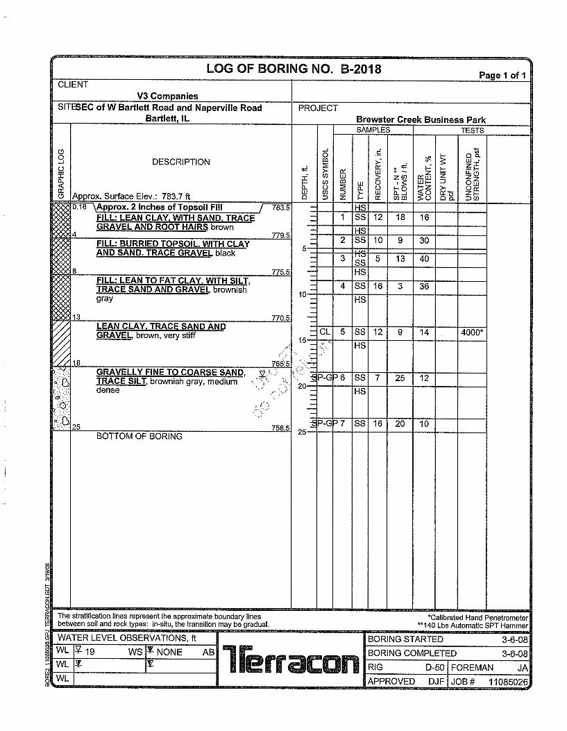


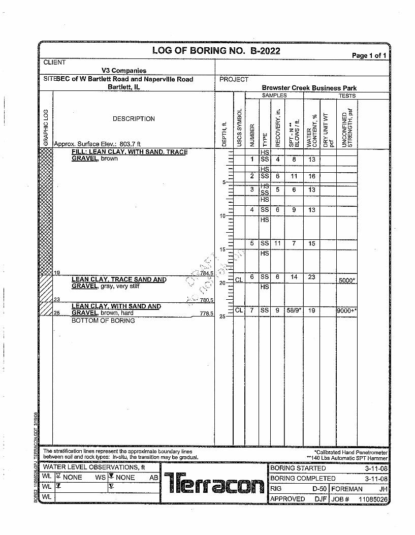
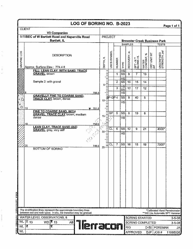

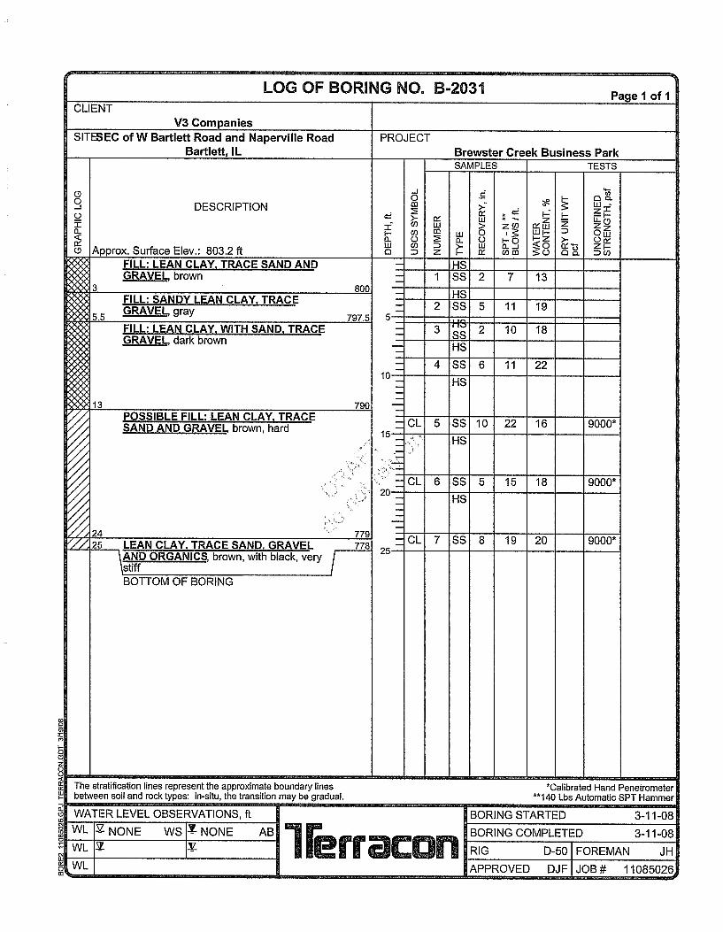
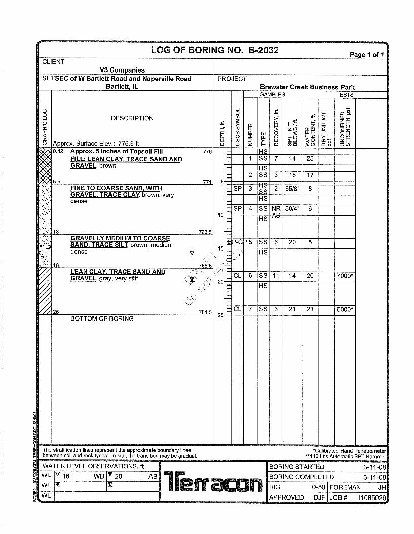
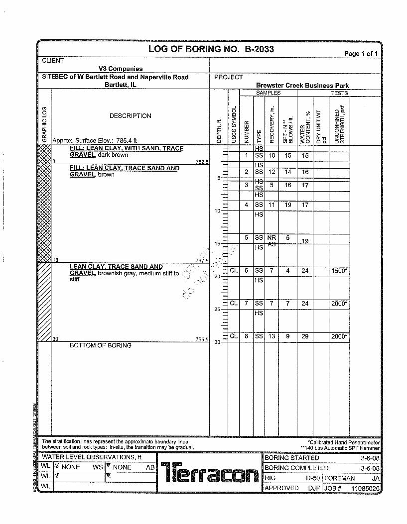
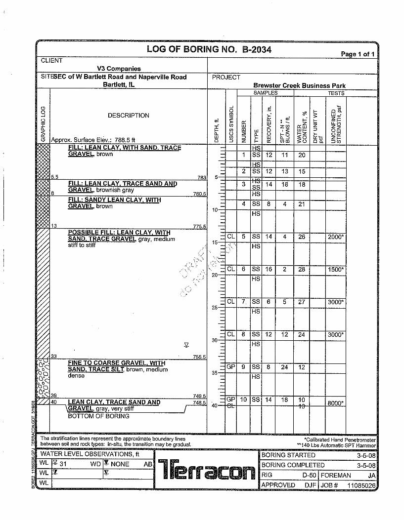

SUPPORTING INFORM ATION
SUPPORTING INFORMATION

Brewster Creek Project Oak Bartlett, Illinois
4/5/2018 Terracon Project No. MR185118
0.25 to 0.50
> 4.00
2.00 to 4.00
1.00 to 2.00
0.50 to 1.00
less than 0.25
Unconfined Compressive StrengthQu, (tsf)
Split Spoon
Trace
PLASTICITY DESCRIPTION
Water levels indicated on the soil boring logs arethe levels measured in the borehole at the timesindicated. Groundwater level variations will occurover time. In low permeability soils, accuratedetermination of groundwater levels is notpossible with short term water levelobservations.
DESCRIPTION OF SYMBOLS AND ABBREVIATIONSGENERAL NOTES
> 30
11 - 30
1 - 10Low
Non-plastic
Plasticity Index
#4 to #200 sieve (4.75mm to 0.075mm
Boulders
12 in. to 3 in. (300mm to 75mm)Cobbles
3 in. to #4 sieve (75mm to 4.75 mm)Gravel
Sand
Passing #200 sieve (0.075mm)Silt or Clay
Particle Size
Water Level Aftera Specified Period of Time
Water Level After aSpecified Period of Time
Water InitiallyEncountered
Soil classification is based on the Unified Soil Classification System. Coarse Grained Soils have more than 50% of theirdry weight retained on a #200 sieve; their principal descriptors are: boulders, cobbles, gravel or sand. Fine Grained Soilshave less than 50% of their dry weight retained on a #200 sieve; they are principally described as clays if they are plastic,and silts if they are slightly plastic or non-plastic. Major constituents may be added as modifiers and minor constituentsmay be added according to the relative proportions based on grain size. In addition to gradation, coarse-grained soils aredefined on the basis of their in-place relative density and fine-grained soils on the basis of their consistency.
GRAIN SIZE TERMINOLOGY
RELATIVE PROPORTIONS OF FINESRELATIVE PROPORTIONS OF SAND AND GRAVEL
DESCRIPTIVE SOIL CLASSIFICATION
LOCATION AND ELEVATION NOTES
SAMPLING WATER LEVEL FIELD TESTSN
(HP)
(T)
(DCP)
UC
(PID)
(OVA)
Standard Penetration TestResistance (Blows/Ft.)
Hand Penetrometer
Torvane
Dynamic Cone Penetrometer
Unconfined CompressiveStrength
Photo-Ionization Detector
Organic Vapor Analyzer
Medium
0Over 12 in. (300 mm)
>12
5-12
<5
Percent ofDry Weight
TermMajor Component of Sample
Modifier
With
Trace
Descriptive Term(s) ofother constituents
>30Modifier
<15
Percent ofDry Weight
Descriptive Term(s) ofother constituents
With 15-29
High
Unless otherwise noted, Latitude and Longitude are approximately determined using a hand-held GPS device. Theaccuracy of such devices is variable. Surface elevation data annotated with +/- indicates that no actual topographicalsurvey was conducted to confirm the surface elevation. Instead, the surface elevation was approximately determined fromtopographic maps of the area.
Standard Penetration orN-Value
Blows/Ft.
Descriptive Term(Density)
CONSISTENCY OF FINE-GRAINED SOILS
Hard
15 - 30Very Stiff> 50Very Dense
8 - 15Stiff30 - 50Dense
4 - 8Medium Stiff10 - 29Medium Dense
2 - 4Soft4 - 9Loose
0 - 1Very Soft0 - 3Very Loose
(50% or more passing the No. 200 sieve.)Consistency determined by laboratory shear strength testing, field visual-manual
procedures or standard penetration resistance
STRENGTH TERMS
> 30
Descriptive Term(Consistency)
Standard Penetration orN-Value
Blows/Ft.
RELATIVE DENSITY OF COARSE-GRAINED SOILS
(More than 50% retained on No. 200 sieve.)Density determined by Standard Penetration Resistance

UNIFIED SOIL CLASSIFICATION SYSTEM
Brewster Creek Project Oak ■ Bartlett, Illinois
April 10, 2018 ■ Terracon Project No. MR185118R1
UNIFIED SOIL C LASSIFIC AT ION SYSTEM
Criteria for Assigning Group Symbols and Group Names Using Laboratory Tests A Soil Classification
Group
Symbol Group Name B
Coarse-Grained Soils:
More than 50% retained
on No. 200 sieve
Gravels:
More than 50% of
coarse fraction
retained on No. 4 sieve
Clean Gravels:
Less than 5% fines C
Cu 4 and 1 Cc 3 E GW Well-graded gravel F
Cu 4 and/or 1 Cc 3 E GP Poorly graded gravel F
Gravels with Fines:
More than 12% fines C
Fines classify as ML or MH GM Silty gravel F, G, H
Fines classify as CL or CH GC Clayey gravel F, G, H
Sands:
50% or more of coarse
fraction passes No. 4
sieve
Clean Sands:
Less than 5% fines D
Cu 6 and 1 Cc 3 E SW Well-graded sand I
Cu 6 and/or 1 Cc 3 E SP Poorly graded sand I
Sands with Fines:
More than 12% fines D
Fines classify as ML or MH SM Silty sand G, H, I
Fines classify as CL or CH SC Clayey sand G, H, I
Fine-Grained Soils:
50% or more passes the
No. 200 sieve
Silts and Clays:
Liquid limit less than 50
Inorganic: PI 7 and plots on or above “A”
line J
CL Lean clay K, L, M
PI 4 or plots below “A” line J ML Silt K, L, M
Organic: Liquid limit - oven dried
0.75 OL Organic clay K, L, M, N
Liquid limit - not dried Organic silt K, L, M, O
Silts and Clays:
Liquid limit 50 or more
Inorganic: PI plots on or above “A” line CH Fat clay K, L, M
PI plots below “A” line MH Elastic Silt K, L, M
Organic: Liquid limit - oven dried
0.75 OH Organic clay K, L, M, P
Liquid limit - not dried Organic silt K, L, M, Q
Highly organic soils: Primarily organic matter, dark in color, and organic odor PT Peat
A Based on the material passing the 3-inch (75-mm) sieve
B If field sample contained cobbles or boulders, or both, add “with cobbles
or boulders, or both” to group name.
C Gravels with 5 to 12% fines require dual symbols: GW-GM well-graded
gravel with silt, GW-GC well-graded gravel with clay, GP-GM poorly graded gravel with silt, GP-GC poorly graded gravel with clay.
D Sands with 5 to 12% fines require dual symbols: SW-SM well-graded
sand with silt, SW-SC well-graded sand with clay, SP-SM poorly graded sand with silt, SP-SC poorly graded sand with clay
E Cu = D60/D10 Cc =
6010
2
30
DxD
)(D
F If soil contains 15% sand, add “with sand” to group name.
G If fines classify as CL-ML, use dual symbol GC-GM, or SC-SM.
H If fines are organic, add “with organic fines” to group name.
I If soil contains 15% gravel, add “with gravel” to group name.
J If Atterberg limits plot in shaded area, soil is a CL-ML, silty clay.
K If soil contains 15 to 29% plus No. 200, add “with sand” or “with
gravel,” whichever is predominant.
L If soil contains 30% plus No. 200 predominantly sand, add
“sandy” to group name.
M If soil contains 30% plus No. 200, predominantly gravel, add
“gravelly” to group name.
N PI 4 and plots on or above “A” line.
O PI 4 or plots below “A” line.
P PI plots on or above “A” line.
Q PI plots below “A” line.