georgia tech nasa critical design review teleconference ppt... · 2017-01-20 · georgia tech nasa...
TRANSCRIPT

Georgia Tech NASA Critical Design Review
TeleconferencePresented By:
Georgia Tech Team ARES
1

Agenda
2
1. Team Overview (1 Min)
2. Changes Since Proposal (1 Min)
3. Educational Outreach (1 Min)
4. Safety (2 Min)
5. Project Budget (2 Min)
6. Launch Vehicle (10 min)
7. Flight Systems (13 Min)
8. Questions (15 Min)

3
TEAM OVERVIEWProject KRIOS- CDR

Georgia Tech Team Overview
4
• 24 person team composed of both undergraduate and graduate students
• Undergraduates: 24
• Highly Integrated team across several disciplines
-Mechanical Engineering
-Aerospace Engineering
-Applied Mathematics
-Electrical Engineering

Work Breakdown Structure
5

6
CHANGES SINCE PDRProject KRIOS - CDR

Changes since PDR
7
Launch Vehicle• ATS System (now removed)
• was advanced to satisfy mechanical and stability concerns• programming concern, not enough active members to push development
• Roll Inducing Mechanism• Servo placement moved to space between 5.5 in tube and Motor tube• Gear system used to mechanically prevent misalignment
• Parachute Compartment Resizing• Subscale proved that over packing can prevent deployment• Compartments have been lengthened using SkyAngle reference sheet + 30% tolerance
• Method of Separation• In the Subscale, ejection charges pushed parachutes into compartments• New design to ensure charges push parachutes out of separated sections
• New Parachutes → 120 in Main, 45 in Drogue (both ~ 0.75 cd)

Changes since PDR
8
Flight Systems
• PIXHAW K replacing IMU, gyroscope, and accelerometer, and Teensy
Project Plan
• Subscale Launch Jan 14th
• Outreach details made for Merit Badge clinic and after school program

9
EDUCATIONAL OUTREACHProject KRIOS - CDR

-Peachtree Charter After School Program
-Boy Scout Merit Badges
-CEISMC GT
-Atlanta Science Festival
Educational Outreach
10

11
SAFETYProject KRIOS - CDR

12
Risk Assessment & Launch VehicleGeneral Objectives
● Proper construction and assembly of both the launch vehicle itself and the launch vehicle recovery
subsystem.
● The majority of dangers/failures can be dealt with during assembly and construction.
● All risks involved will be mitigated as long as team members follow all safety guidelines while
constructing and launching the launch vehicle
● A successful launch will include successful recovery as well as no injuries whatsoever to any team
member.
13
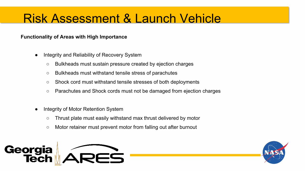
Risk Assessment & Launch VehicleFunctionality of Areas with High Importance
● Integrity and Reliability of Recovery System
○ Bulkheads must sustain pressure created by ejection charges
○ Bulkheads must withstand tensile stress of parachutes
○ Shock cord must withstand tensile stresses of both deployments
○ Parachutes and Shock cords must not be damaged from ejection charges
● Integrity of Motor Retention System
○ Thrust plate must easily withstand max thrust delivered by motor
○ Motor retainer must prevent motor from falling out after burnout

14
Risk Assessment & Launch VehicleContinued…
● Stability Impacts of Roll Induction Mechanism
○ All flaps must be in same angled position at all times
○ Max servo power draw should never exceed supply
○ Susceptibility of Avionics Equipment to Environmental Effects
○ Altimeters must not be affected by the pressures created by ejection charges

15
PROJECT BUDGETProject KRIOS - CDR
16
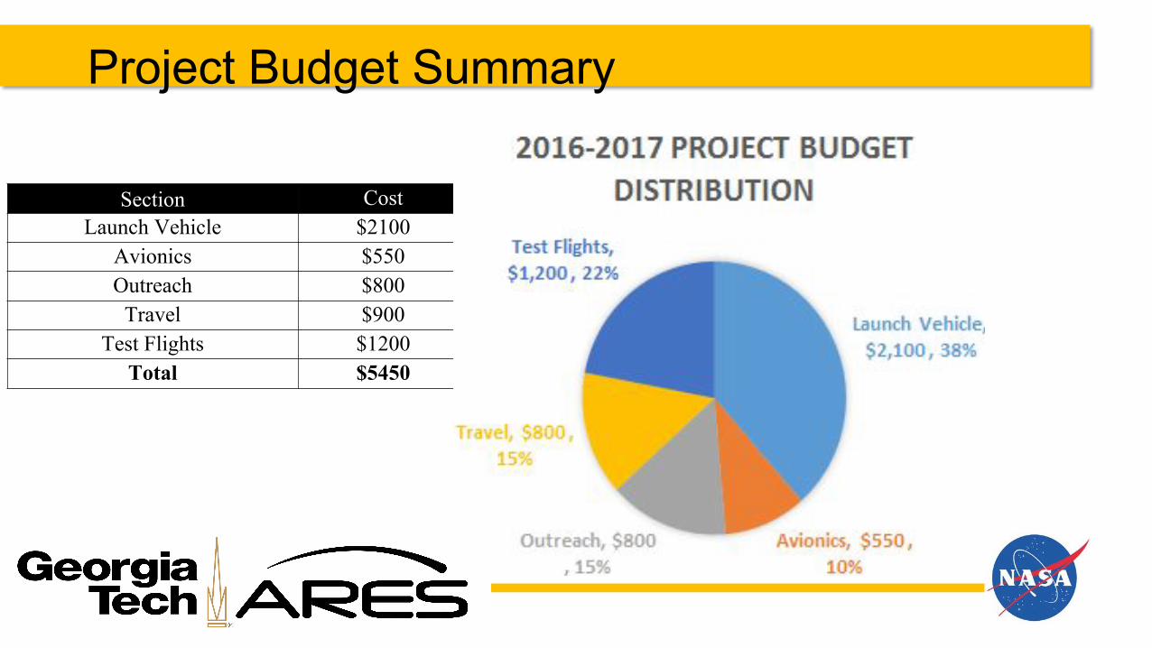
Project Budget Summary
Section CostLaunch Vehicle $2100
Avionics $550Outreach $800
Travel $900Test Flights $1200
Total $5450

17
Verification Plan Status
Creating accurate model for WATES- collected subscale data
Maximum accessibility and minimum setup- redesigned A-bay
Ensuring dual redundancy and parachute deployment- designing larger couplers and better parachute packing systems, offset altimeter charges

18
LAUNCH VEHICLEProject KRIOS - CDR

19
Launch Vehicle Summary● Predicted apogee: 5297 ft
● Stability margin: 2.47 calibers
● Motor: Cesaroni L1150R
● Main Chute: TFR 120 in, 0.75 cd
● Drogue Chute: TFR 45 in, 0.75 cd
● Shock Cord Size: 1 in Tubular Nylon
● Shock Cord Length: 36 ft total
● Velocity off 8 ft Rail: 61.3 ft/s
● Max Velocity: 0.5767 mach
● Total weight: 545 oz

20
Fins
● Consists of one main fin, one hinge mechanism, and one flap
● Fin and flap are made from fiberglass, hinge mechanism made from strong steel material
● Fin and flap size chosen after analyzing OpenRocket CP locations

21
Roll Control System
● The launch vehicle is to be outfitted with 4 adjustable fins attached to the end of 4 stationary fins
● large gear ring that will constrain all the variable fins to the same orientation

22
Booster SectionMaterials and Manufacturing:
● Centering Rings: G10 Fiberglass, Waterjet● Cardboard Tube: Circular Saw● Thrust Plate: Plywood, Laser Cutter
Assembly1. Rings epoxied to exact locations
along motor tube2. Thrust plate epoxied to outer 5.5 in
tube3. Centering rings epoxied to outer 5.5
in tube4. Then fins can be mounted over
bottom centering ring5. Roll induction system installed
between 5.5 in tube and motor tube
Verification of integrity under max load

23
Motor SelectionTechnical Specifications
● Aerotech L1150● Diameter: 75mm● Propellant: APCP● Casing: RMS 75/3840● Avg Thrust: 247.4 lb● Total Impulse: 784.3 lbf-s● Loaded Mass: 130 oz● Post-Burnout Mass: 56.7 oz● Predicted Apogee 5297 ft
Reasons for Selection
● Higher avg. thrust than other of similar impulse● More time to control roll-induction mechanism● Results in most reasonably close apogee
○ Predicted apogee assumes about 65 oz of added mass
○ Unexpected weight of fasteners and epoxy can be compensated by removing from MAS and CG Adjustment system
○ Subscale was heavier than predicted● No other motor available that came close to same impulse

24
Avionics Bay - Separation
2-56 Nylon Shear Pins 4x Steel Rivets 4x 2-56 Nylon Shear Pins 4x
Ejection charge canister Blast Caps

25
Avionics Bay - Assembly
Assembly Description● Tray riding on two threaded rods, fixed in place via nuts● Bulkheads are 2-piece assemblies to make better air seal● Bulkheads clamped on each side of coupler tube with nuts● 2 master key switches● One coupler end has shear pin holes, the other has larger holes
for rivets
Things Learned From Subscale Launch:● Wiring both ends of bay become difficult when
bulkheads are epoxied in● Less wire = less chance of tangling and pulling
connections loose● Nuts come loose from vibrations → use loctite
26
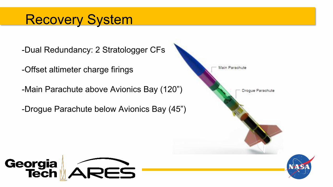
Recovery System
-Dual Redundancy: 2 Stratologger CFs
-Offset altimeter charge firings
-Main Parachute above Avionics Bay (120”)
-Drogue Parachute below Avionics Bay (45”)

27
Kinetic Energy at Landing
Section Mass (oz) Kinetic Energy after
Drogue Deployment (ft-lbf)
Kinetic Energy after Main
Deployment (ft-lbf)
Booster (empty) 261.7 633.63 72.2
Avionics 114.2 347.57 39.59
Nosecone 96.8 294.62 33.55
Using a 120” main parachute and 45” drogue parachute, the rocket will land at 18.9 ft/s
KE= .5*m*v2
75ft-lbf >= .5*msection*(18.9ft/s)2

28
Mass Breakdown

29
Thrust-to-Weight Ratio *
Max thrust from L1150 = 294.4lbs
294.4lbs/34lbs = 8.8

30
Rocket Flight Stability Variable Value
Stability 2.6 cal
Centre of Gravity 67.887 in
Centre of Pressure 82.346 in
31
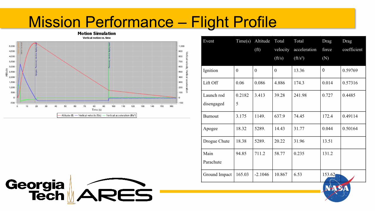
Mission Performance – Flight ProfileEvent Time(s) Altitude
(ft)
Total
velocity
(ft/s)
Total
acceleration
(ft/s²)
Drag
force
(N)
Drag
coefficient
Ignition 0 0 0 13.36 0 0.59769
Lift Off 0.06 0.086 4.886 174.3 0.014 0.57316
Launch rod
disengaged
0.2182
5
3.413 39.28 241.98 0.727 0.4485
Burnout 3.175 1149. 637.9 74.45 172.4 0.49114
Apogee 18.32 5289. 14.43 31.77 0.044 0.50164
Drogue Chute 18.38 5289. 20.22 31.96 13.51
Main
Parachute
94.85 711.2 58.77 0.235 131.2
Ground Impact 165.03 -2.1046 10.867 6.53 153.62

32
Mission Performance - Drift Profile

33
Subscale Launch Results
Flight 1- Apogee 3145ft
Flight 2- Apogee 3166ft

34
Subscale Launch Results- Design Changes
● Avioinics Bay rehaul- more accessibility● WATES effective system● Offset altimeter deployment signals● Smaller keyswitches● Switching main and drogue parachute locations

35
FLIGHT SYSTEMSProject KRIOS - PDR

36
Flight System Responsibilities Outline of Success Criteria
Requirement Design Feature to Satisfy Requirement
Requirement Verification Success Criteria
The vehicle shall not exceed an apogee of 5,280 feet
Calculated rocket mass Full-scale flight test Apogee within 1% of target
The vehicle will be tracked in real- time to locate and recover it
Eggfinder GPS module will be used in the vehicle and base station
Full-scale flight test The vehicle will be located on a map after it lands for recovery
The data of the vehicle’s flight will be recorded
Pixhawk has sd card storage Full-scale flight test The data will be recovered and readable after flight
The vehicle will complete a moment and counter moment inducing roll
Pixhawk servo rail will strategically actuate motor system.
Full-scale flight test Rolling at least 2 full rotations, and rotating the other way to the initial position

37
Flight Systems: Avionics
Part Function
Stratologger SL100 Altimeter - used to receive and record altitude
Pixhawk px4 Autopilot control system. equipped with 9 DOF MEMS and 14 pwm_out.
Air Speed sensor Reports exterior air speed. USeful for roll calculations.
Eggfinder TX/RX Module GPS module - used to track the rocket in real time
9V Alkaline Batteries Used to power all Avionics components and ATS
Avionics Components

38
Flight Systems: AvionicsRecovery System
39
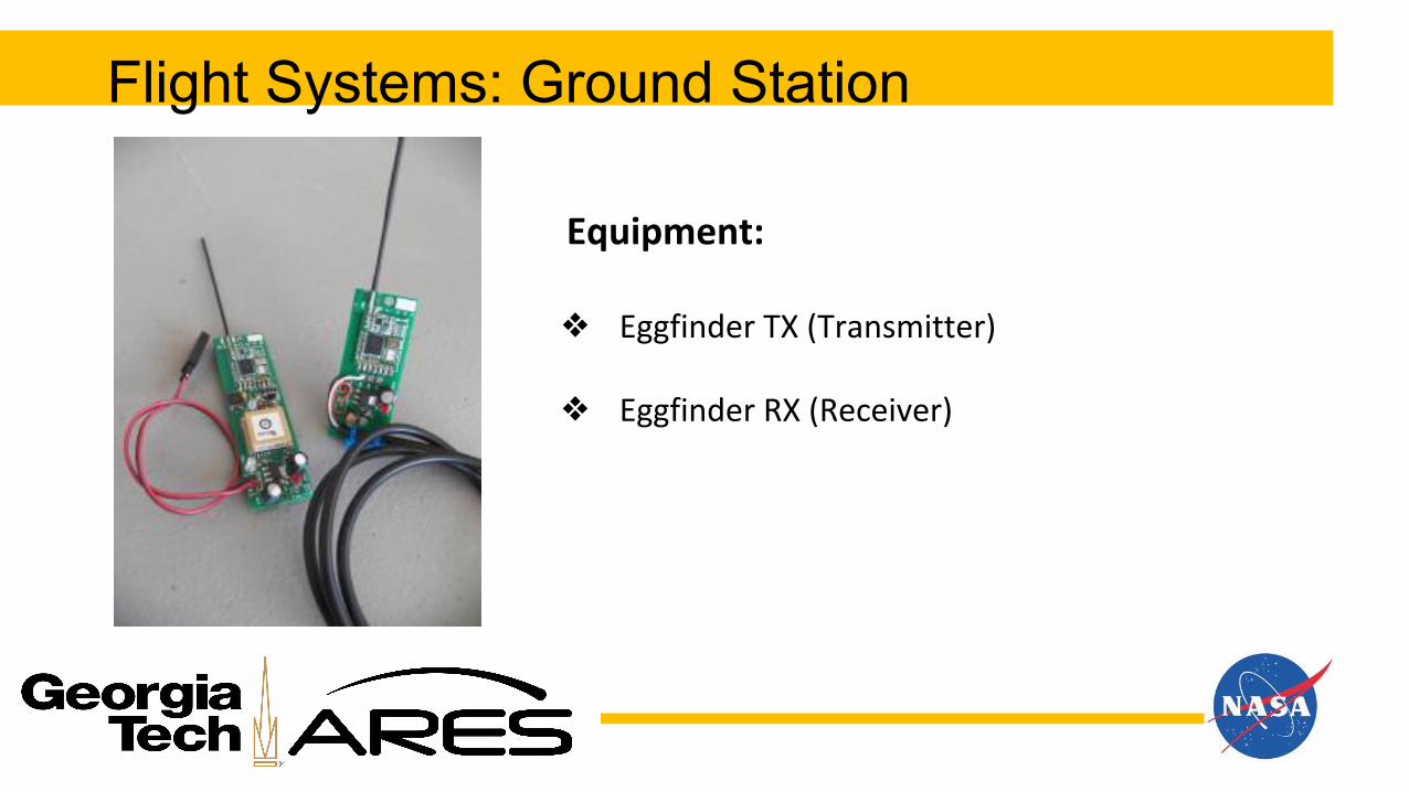
Flight Systems: Ground Station
Equipment:
❖ Eggfinder TX (Transmitter)
❖ Eggfinder RX (Receiver)

40
Payload Integration
❖ Roll Control- 4 servos hooked up to power and Pixhawk in Avionics bay through disconnectable wiring lining down the booster section
❖ Altimeters hooked up to ejection charges in coupler sections
❖ Servos connected to shafts turning the fin flaps

41
Interfaces
● Pixhawk controls servos actuating roll control flaps
● GPS sending signals to a ground receiver
● Altimeters hooked up to ejection charges in coupler sections

42
Flight Systems: System Block Diagram

43
Flight Systems: ATS Power
● 9-volt alkaline batteries will be used independently to power each stratologger altimeter as well as the Pixhawk
● High torque servo motors will be used to actuate roll flaps. An independent 7.4V NiMH source will be used to power the servo rail.

44
Flight Systems: Testing OverviewWind Tunnel: Test flap actuation under load
Flight Simulation: simulated flight data will be tested for run-time efficiency to ensure that calculations can be completed both accurately and timely.
Power Consumption: Full charged power supply will be connected to flight systems to see its maximum lifespan.ANSYS
Stress Tests -Bulkheads, Thrust Plate
Ejection Charges
Questions?
Questions
45